1
A Draft of Guidance from the Scientific Research Programme GEOTECHNOLOGIEN to Underpin the Implementation of the CCS Directive in Germany Introduction Within the GEOTECHNOLOGIEN funding scheme for geological CO storage by the Federal Ministry of Education and Research (BMBF) in Germany 32 projects have been funded 2 with a budget of 58,3 M€ excluding industry funds from 2005 to 2014. In 2012 the German government passed the transposition of the EU CCS Directive 2009/31/EG – Das Kohlendioxid-Speicherungsgesetz (KSpG). Beside differences of both laws Annexe 1 and 2 match which define the criteria how to set up and monitor a CO storage. In 2012 an 2 umbrella project called AUGE has been launched in order to compile and summarise the results of the projects to underpin the Annexe scientifically. This presentation gives a draft overview of the project results ordered by the KSpG with an assessment of the development status. Nomenclature status: prototype: method developed in the project based on the physical principal, available to developing research groups demonstration: method well tested within a project, in principal available to the storage community established: method well tested before or available on the market Axel Liebscher, Martin Streibel and Birgit Schöbel Helmholtz Centre Potsdam, GFZ - German Research Centre for Geosciences, Centre for Geological Storage, Potsdam, Germany Annex 1: Criteria for the characterisation and assessment of the potential storage complex and surrounding area 1.1 Data collection Table 1: Summary of deployed and developed characterisation techniques. 1.2 Building the three-dimensional static geological earth model 1.3 Characterisation of the storage dynamic behaviour and sensitivity characterisation Table 2: Brief summary of methods to establish a static geolgocial model. Fig. 1: Workflow for dynamic modelling. Table 3: Brief summary of methods to establish a dynamic model as described in Figure 1. Benchmark, CO SINK, CO MAN, 2 2 CO RINA, CLEAN, 2 BRINE, CO MOPA 2 As a prerequisite for a comprehensive risk analysis within the risk assessment simplified versions of models deployed in characteri-sation should be used and coupled in an statistical approach. Project Modelling activity Status demon- stration Development of fully coupled dynamic models to simulate the effects of injection of CO into the subsurface: multi- 2 phase flow, heat transport, hydrodynamics, geomechanics and chemistry with various simulators and sub-models -> THMC models, shown in Fig. 1. Individual modules of model systems need to be evaluated by benchmarks. Models need to be calibrated with monitoring data. Prediction of the CO flow in the subsurface will be very uncertain as it depends 2 strongly on small-scale heterogeneity and large-scale geologic features Prediction of pressure development in the storage complex can be given with some confidence as it depends mainly on the average permeability. Prediction on the storage capacity can be estimated with some uncertainty as it depends on the injection rate, depth, temperature, salinity, permeability. Prediction on geochemistry and geomechanics can be estimated with a big uncertainty mainly due to missing data and missing fundamental constants. established Project Methodology Status CO SINK 2 CLEAN CO MAN 2 CO CRS 2 CO DEPTH 2 PROTECT CSEGR COMICOR established geologic field mapping, well logs for near well parameters, hydrologic field experiments, usage of different reactive tracers established- demon- stration 4D seismics at pilot site Ketzin, improvement of analysis of seismic data, approach of combining seismic data analysis with 3D kinematic modelling for an improved understanding of fault (re)activation determination of petrophysical reservoir parameters and mineral composition, batch experiments for CO -rock interaction 2 There is a good understanding of the reactivity of individual minerals with scCO -H O 2 2 which allows a correct evaluation of the reservoir rock. However in batch experiments rocks show a higher reactivity than in real life (coring at Ketzin). Chemical modelling is limited due to missing thermodynamic constants and kinetic rates. CO SONO- 2 StRA batch experiments with cores, scCO , formation fluid and impurities NO , SO 2 2 2 and O showed some damage within the 28 days testing period – concentra- 2 tion of impurities used were too big than today's capture technology suggest CO SINK 2 CO MAN 2 RECOBIO CO BIOPERM 2 At Ketzin the microbiological community in the dump of the well changed during injection but still exists. An influence on the permeability of cores infiltrated by microorganisms has not been proven jet but is a focus of CO BIOPERM. 2 CO TRAP 2 COSMOS CO SEALS 2 batch experiments of scCO -water-clay show 2 a very low reaction rate: alteration are insignificant for the tested time periods that clay stones with a significant amount of Smectit, Illite and Kaolinite have a high CO sorption potential 2 CO SINK, CLEAN, BRINE, 2 CO MOPA, CO MAN 2 2 Among others Petrel, GOCAD, EarthVision are software packages to generate static 3D geological models. established Project Methodology Status Geo-statistic is needed to derive petrophysical parameters from few drilling cores for the whole modelling grid but therefore cannot reproduce preferential pathways of the CO 2 plume flow. An appropriate fault model needs to be developed and implemented. The static geological model as a base for dynamic model runs will be improved by further monitoring data with ongoing CO injection and other measurements. 2 The approaches “one geological model fits all” versus “a number of simplified geological models for different parameters” need to be considered, Fig. 1. Geol. M.1 Thermal: heat transport Geochemical: transport and reactions Mechanical: deformation Hydraulic: fluid dynamics Sensitivity studies of individual processes Long-term simulations Risk assessment Simplified static geological models Simplified models Simplified models dynamic model coupling benchmarks for individual sub-modules History match for parameters, „best“ comprehensive model The knowledge base of CO storage research is good enough to start a demonstration 2 project (injection of 1 Mt CO ). 2 It is actually needed to progress the technology. Summary Wellbore integrity Table 4: Brief summary on wellbore integrity. Fig. 2: Schematic showing the use of clay or salt as an additional barrier in wellbore abandonment. CO 2 CO reservoir 2 cement casing closed reservoir with gel cement milled borehole barred well by clay pellets bridge plug salt cap rock salt plug, impermeable, CO resistant 2 COBOHR COBRA cement prototype elimination of imperfections in wellbore cements by optimizing 1. the viscosity/ hardening of the cement using different by-products 2. the filling technology Oil and gas production proves that wellbores are safe for 50+ years, new materials suggest that for CO storage as well. 2 The conservation of the technical integrity of abandoned wells for more than hundred of years remains unproven. A higher level of security can be achieved by introducing natural barriers wherever possible (Fig. 2), CLEAN. Project Part Technology Status CSEGR COSMOS well fitting established steel and other materials are available in which are resistant against corrosion COSMOS COBOHR COBRA cement advanced cements have been developed to withstand the corrosion by carbonic acid by an increase of NaCl or replacement of Portland cement clinker with quartz powder or flue ash prototype MONACO CO MAN 2 FTIR, Eddy covariance, CO sensors in the soil - 2 down to 20 m CO 2 concentration on surface of storage area established CO Leckage, 2 MONACO, SAMOLEG fluid electrical resistance, salinity, chemical parameter established ground water monitoring tools, long electrodes ERT drinking water aquifer established electrical and magnetic fields (EM) down to 200 m salinity – salt water induced zone BRINE MONACO established wellhead and in wellbore CO MAN 2 p/T established CO MAN 2 T distributed temperature sensing wellbore demon- stration COBRA cement permittivity time delayed resistivity wellbore prototype CO MAN 2 various parameter of the wellbore various wellbore established CO MAN 2 BRINE electric resistivity of fluids ERT in wellbore and or surface demon- stration CO MAN 2 CHEMKIN concentration of substances gas membrane sampling device connect to gas chromatograph in wellbore demon- stration established MONACO CO MAN 2 surface deformation satellite imagery for movement of reflectors, GPS measurements of emitters surface of storage area established CO MAN 2 seismic waves active seismics surface of storage area, wellbore CO MAN 2 neutron scattering, electrical resistivity, CO saturation 2 pulsed neutron gamma, ERT wellbore demon- stration Project Parameter monitored Technology Location Status CO MAN 2 seismic waves geophones, passive seismics wellbore, surface established Reservoir Intermediate region – last drinking water aquifer to cap rock of storage reservoir Borehole Drinking water aquifers Verification measurements Surface and above Monitoring Table 5: Proven and developed monitoring methods. Annex 2: Criteria for establishing and updating the monitoring plan and for post-closure monitoring Establishing the monitoring plan In the GEOTECHNOLOGIEN Program technologies have been developed and applied which allow for a comprehensive monitoring on all levels. It is most efficient to implement the monitoring strategy based on the site characterisation, close to planes of weakness, implement a hierarchical approach, with low resolution spatial measurements with a relatively high timely resolution which are complemented with high resolution spatial measurements at individual locations where anomalies have been detected. Most challenging is the monitoring of the region between the cap rock of the CO storage 2 reservoir and the drinking water aquifers as CO can spread laterally in overlaying aquifers, 2 especially the task to find new leakage pathways if site characterisation has given no indication, the detection of fluid migration in the vicinity of the storage with elevated pressure levels. Surface measurements of CO should be seen as verification measurements rather than 2 monitoring measurements. They need to be done but probably most damage has been done once CO is detected at the surface. 2 Updating the monitoring plan This is one of the most important steps in the life cycle of a CO storage: The 2 adaption/improvement of the static geological earth model (Annex 1.1) with new measurement data is an iterative process. CO can be seen as a tracer for reservoir 2 characterisation and gives additional information about the heterogeneity of the reservoir. Most important is to understand the change of geophysical properties of the reservoir and the cap rock over time with ongoing injection, the difference between modelled and measured behaviour of the storage complex as signals of leakage might be subtle and fall into the uncertainty of modelled parameters. Post-closure monitoring The short post-closure period at the pilot site for CO storage at Ketzin has shown that 2 P/T measurements in the wellbores near the reservoir and in aquifers above the reservoirs are most valuable to understand the pressure decrease within the reservoir, DTS in the wellbores help to understand the thermodynamic phase behaviour of CO 2 along the sonde, Mapping of the CO plume by seismic measurements will provide confidence in the 2 integrity of the reservoir by understanding plume migration. Acknowledgment The scientific content of this poster was aquiered by the GEOTECHNOLOGIEN projects as referred to under "Project". We are especially grateful to our colleagues of Phase 3 projects for their input to the Guidance Document.

A Draft of Guidance from the Scientific Research Programme ...conference.co2geonet.com/media/1118/a-draft-of-guidance-from-the... · A Draft of Guidance from the Scientific Research

Embed Size (px)

Citation preview

A Draft of Guidance from the Scientific Research Programme GEOTECHNOLOGIENto Underpin the Implementation of the CCS Directive in Germany

Introduction

Within the GEOTECHNOLOGIEN funding scheme for geological CO storage by the Federal Ministry of Education and Research (BMBF) in Germany 32 projects have been funded 2

with a budget of 58,3 M€ excluding industry funds from 2005 to 2014. In 2012 the German government passed the transposition of the EU CCS Directive 2009/31/EG – Das Kohlendioxid-Speicherungsgesetz (KSpG). Beside differences of both laws Annexe 1 and 2 match which define the criteria how to set up and monitor a CO storage. In 2012 an 2

umbrella project called AUGE has been launched in order to compile and summarise the results of the projects to underpin the Annexe scientifically. This presentation gives a draft overview of the project results ordered by the KSpG with an assessment of the development status.

Nomenclature status:prototype: method developed in the project based on the physical principal, available to developing research groupsdemonstration: method well tested within a project, in principal available to the storage communityestablished: method well tested before or available on the market

Axel Liebscher, Martin Streibel and Birgit SchöbelHelmholtz Centre Potsdam, GFZ - German Research Centre for Geosciences,

Centre for Geological Storage, Potsdam, Germany

Annex 1: Criteria for the characterisation and assessment of the potential storage complex and surrounding area

1.1 Data collection

Table 1: Summary of deployed and developed characterisation techniques.

1.2 Building the three-dimensional static geological earth model

1.3 Characterisation of the storage dynamic behaviour and sensitivitycharacterisation

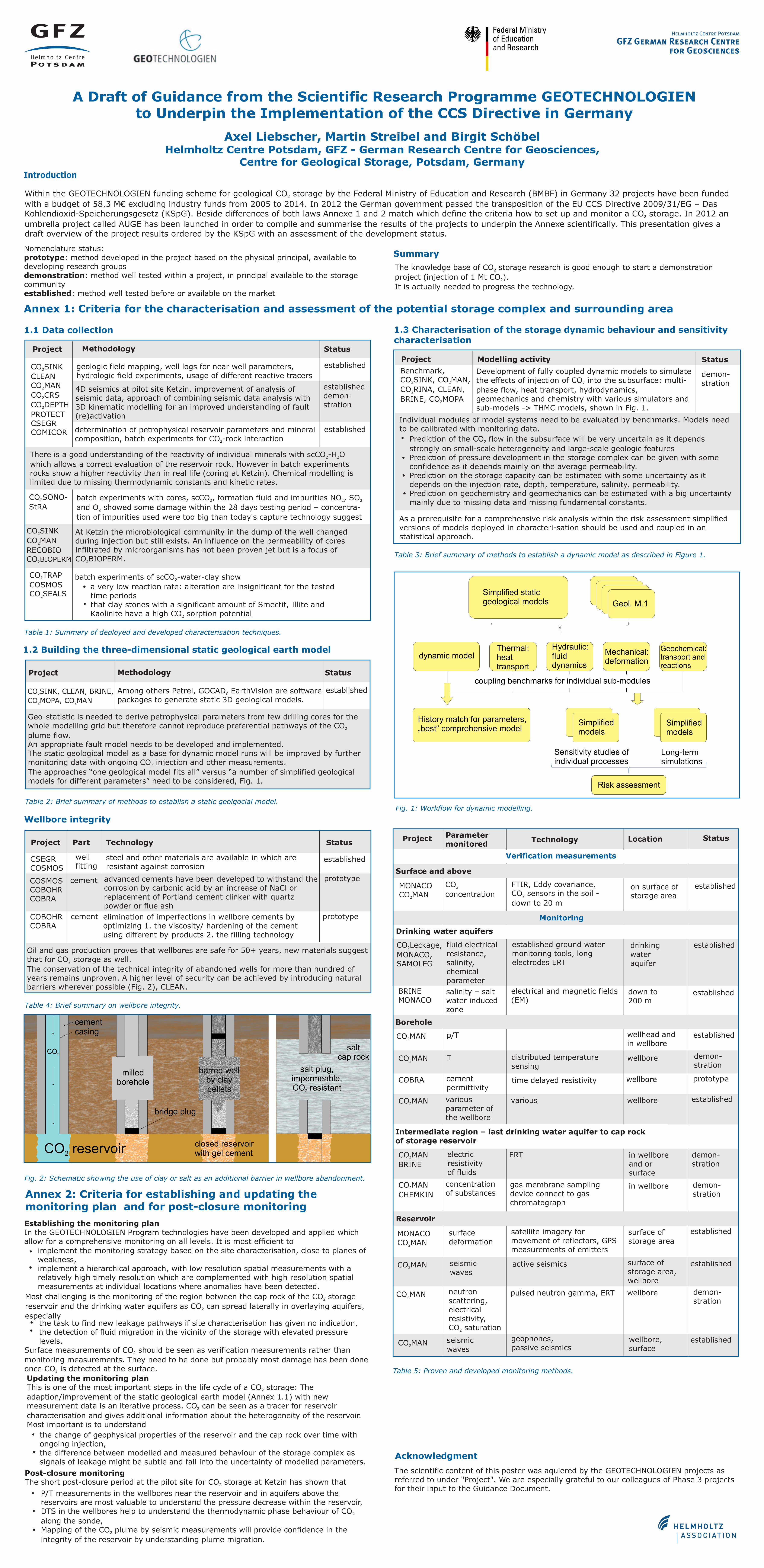
Table 2: Brief summary of methods to establish a static geolgocial model.Fig. 1: Workflow for dynamic modelling.

Table 3: Brief summary of methods to establish a dynamic model as described in Figure 1.

Benchmark,CO SINK, CO MAN,2 2

CO RINA, CLEAN,2

BRINE, CO MOPA2

As a prerequisite for a comprehensive risk analysis within the risk assessment simplified versions of models deployed in characteri-sation should be used and coupled in an statistical approach.

Project Modelling activity Status

demon-stration

Development of fully coupled dynamic models to simulate the effects of injection of CO into the subsurface: multi-2

phase flow, heat transport, hydrodynamics, geomechanics and chemistry with various simulators and sub-models -> THMC models, shown in Fig. 1.

Individual modules of model systems need to be evaluated by benchmarks. Models need to be calibrated with monitoring data.

Prediction of the CO flow in the subsurface will be very uncertain as it depends 2

strongly on small-scale heterogeneity and large-scale geologic features Prediction of pressure development in the storage complex can be given with some confidence as it depends mainly on the average permeability.Prediction on the storage capacity can be estimated with some uncertainty as it depends on the injection rate, depth, temperature, salinity, permeability.Prediction on geochemistry and geomechanics can be estimated with a big uncertainty mainly due to missing data and missing fundamental constants.

established

Project Methodology Status

CO SINK2

CLEANCO MAN2

CO CRS2

CO DEPTH2

PROTECTCSEGRCOMICOR

establishedgeologic field mapping, well logs for near well parameters, hydrologic field experiments, usage of different reactive tracers

established-demon-stration

4D seismics at pilot site Ketzin, improvement of analysis of seismic data, approach of combining seismic data analysis with 3D kinematic modelling for an improved understanding of fault (re)activation

determination of petrophysical reservoir parameters and mineral composition, batch experiments for CO -rock interaction2

There is a good understanding of the reactivity of individual minerals with scCO -H O 2 2

which allows a correct evaluation of the reservoir rock. However in batch experiments rocks show a higher reactivity than in real life (coring at Ketzin). Chemical modelling is limited due to missing thermodynamic constants and kinetic rates.

CO SONO-2

StRAbatch experiments with cores, scCO , formation fluid and impurities NO , SO 2 2 2

and O showed some damage within the 28 days testing period – concentra-2

tion of impurities used were too big than today's capture technology suggest

CO SINK2

CO MAN2

RECOBIOCO BIOPERM2

At Ketzin the microbiological community in the dump of the well changed during injection but still exists. An influence on the permeability of cores infiltrated by microorganisms has not been proven jet but is a focus of CO BIOPERM.2

CO TRAP2

COSMOSCO SEALS2

batch experiments of scCO -water-clay show2

a very low reaction rate: alteration are insignificant for the tested time periods that clay stones with a significant amount of Smectit, Illite and Kaolinite have a high CO sorption potential2

CO SINK, CLEAN, BRINE,2

CO MOPA, CO MAN2 2

Among others Petrel, GOCAD, EarthVision are software packages to generate static 3D geological models.

established

Project Methodology Status

Geo-statistic is needed to derive petrophysical parameters from few drilling cores for the whole modelling grid but therefore cannot reproduce preferential pathways of the CO 2

plume flow. An appropriate fault model needs to be developed and implemented.The static geological model as a base for dynamic model runs will be improved by further monitoring data with ongoing CO injection and other measurements. 2

The approaches “one geological model fits all” versus “a number of simplified geological models for different parameters” need to be considered, Fig. 1.

Geol. M.1

Thermal:heattransport

Geochemical:transport andreactions

Mechanical:deformation

Hydraulic:fluiddynamics

Sensitivity studies ofindividual processes

Long-termsimulations

Risk assessment

Simplified staticgeological models

Simplifiedmodels

Simplifiedmodels

dynamic model

coupling benchmarks for individual sub-modules

History match for parameters,„best“ comprehensive model

The knowledge base of CO storage research is good enough to start a demonstration 2

project (injection of 1 Mt CO ).2

It is actually needed to progress the technology.

Summary

Wellbore integrity

Table 4: Brief summary on wellbore integrity.

Fig. 2: Schematic showing the use of clay or salt as an additional barrier in wellbore abandonment.

CO2

CO reservoir2

cementcasing

closed reservoirwith gel cement

milledborehole

barred wellby claypellets

bridge plug

saltcap rock

salt plug,impermeable,CO resistant2

COBOHRCOBRA

cement prototypeelimination of imperfections in wellbore cements by optimizing 1. the viscosity/ hardening of the cement using different by-products 2. the filling technology

Oil and gas production proves that wellbores are safe for 50+ years, new materials suggest that for CO storage as well. 2

The conservation of the technical integrity of abandoned wells for more than hundred of years remains unproven. A higher level of security can be achieved by introducing natural barriers wherever possible (Fig. 2), CLEAN.

Project Part Technology Status

CSEGRCOSMOS

wellfitting

establishedsteel and other materials are available in which are resistant against corrosion

COSMOSCOBOHRCOBRA

cement advanced cements have been developed to withstand the corrosion by carbonic acid by an increase of NaCl or replacement of Portland cement clinker with quartz powder or flue ash

prototypeMONACOCO MAN2

FTIR, Eddy covariance,CO sensors in the soil -2

down to 20 m

CO2

concentrationon surface ofstorage area

established

CO Leckage,2

MONACO,SAMOLEG

fluid electricalresistance,salinity,chemicalparameter

established ground watermonitoring tools, longelectrodes ERT

drinkingwateraquifer

established

electrical and magnetic fields(EM)

down to200 m

salinity – saltwater inducedzone

BRINEMONACO

established

wellhead andin wellbore

CO MAN2p/T established

CO MAN2T distributed temperature

sensingwellbore demon-

stration

COBRA cementpermittivity

time delayed resistivity wellbore prototype

CO MAN2variousparameter ofthe wellbore

various wellbore established

CO MAN2

BRINE

electricresistivityof fluids

ERT in wellboreand orsurface

demon-stration

CO MAN2

CHEMKIN

concentrationof substances

gas membrane samplingdevice connect to gaschromatograph

in wellbore demon-stration

establishedMONACOCO MAN2

surfacedeformation

satellite imagery formovement of reflectors, GPSmeasurements of emitters

surface ofstorage area

establishedCO MAN2seismicwaves

active seismics surface ofstorage area,wellbore

CO MAN2neutronscattering,electricalresistivity,CO saturation2

pulsed neutron gamma, ERT wellbore demon-stration

Project Parametermonitored

Technology Location Status

CO MAN2seismicwaves

geophones,passive seismics

wellbore,surface

established

Reservoir

Intermediate region – last drinking water aquifer to cap rockof storage reservoir

Borehole

Drinking water aquifers

Verification measurements

Surface and above

Monitoring

Table 5: Proven and developed monitoring methods.

Annex 2: Criteria for establishing and updating the monitoring plan and for post-closure monitoring

Establishing the monitoring planIn the GEOTECHNOLOGIEN Program technologies have been developed and applied which allow for a comprehensive monitoring on all levels. It is most efficient to

implement the monitoring strategy based on the site characterisation, close to planes of weakness,implement a hierarchical approach, with low resolution spatial measurements with a relatively high timely resolution which are complemented with high resolution spatial measurements at individual locations where anomalies have been detected.

Most challenging is the monitoring of the region between the cap rock of the CO storage 2

reservoir and the drinking water aquifers as CO can spread laterally in overlaying aquifers, 2

especiallythe task to find new leakage pathways if site characterisation has given no indication,the detection of fluid migration in the vicinity of the storage with elevated pressure levels.

Surface measurements of CO should be seen as verification measurements rather than 2

monitoring measurements. They need to be done but probably most damage has been done once CO is detected at the surface.2

Updating the monitoring planThis is one of the most important steps in the life cycle of a CO storage: The 2

adaption/improvement of the static geological earth model (Annex 1.1) with new measurement data is an iterative process. CO can be seen as a tracer for reservoir 2

characterisation and gives additional information about the heterogeneity of the reservoir.Most important is to understand

the change of geophysical properties of the reservoir and the cap rock over time with ongoing injection,the difference between modelled and measured behaviour of the storage complex as signals of leakage might be subtle and fall into the uncertainty of modelled parameters.

Post-closure monitoringThe short post-closure period at the pilot site for CO storage at Ketzin has shown that 2

P/T measurements in the wellbores near the reservoir and in aquifers above the reservoirs are most valuable to understand the pressure decrease within the reservoir,DTS in the wellbores help to understand the thermodynamic phase behaviour of CO 2

along the sonde,Mapping of the CO plume by seismic measurements will provide confidence in the 2

integrity of the reservoir by understanding plume migration.

Acknowledgment

The scientific content of this poster was aquiered by the GEOTECHNOLOGIEN projects as referred to under "Project". We are especially grateful to our colleagues of Phase 3 projects for their input to the Guidance Document.