Embed Size (px)
Citation preview

A Directional Diffusion Algorithm for Inpainting
Jan Deriu, Rolf Jagerman, Kai-En TsayDepartment of Computer Science, ETH Zurich, Switzerland
Abstract—The problem of inpainting involves reconstructingthe missing areas of an image. Inpainting has many appli-cations, such as reconstructing old damaged photographs orremoving obfuscations from images. In this paper we presentthe directional diffusion algorithm for inpainting. Typicaldiffusion algorithms are bad at propagating edges from theimage into the unknown masked regions. The directionaldiffusion algorithm improves on the regular diffusion algorithmby reconstructing edges more accurately. It scores betterthan regular diffusion when reconstructing images that areobfuscated by a text mask.
I. INTRODUCTION
Automatically reconstructing the missing areas of animage is an inference task often referred to as inpainting.It is commonly used to restore old damaged photographsor to remove objects from an image [1]. A variety ofapproaches have been proposed in the literature to solve thisproblem. Many successful algorithms use a diffusion-basedapproach where local pixel information is propagated intothe missing areas of an image [2]. Other approaches involvethe reconstruction of the full image based on wavelets ordictionaries [3], [4].
In this paper we introduce a novel algorithm that solvesthe inpainting task by using directional diffusion. Thisapproach is based on the fast diffusion algorithm describedby McKenna et al. [5]. It attempts to improve on the fastdiffusion algorithm by taking into account the directionalityof parts of the image to select proper diffusion kernels.
The paper is structured in several sections. First we willdescribe the methods we use to accomplish the inpaintingtask in section II. Next we will discuss the results ofour methods in section III and compare them to severalbaselines. In section IV the strengths and weaknesses of ournovel approach are discussed. Finally the paper is concludedin section V.
II. METHODS
We present two algorithms that accomplish the inpaintingtask: regular diffusion and directional diffusion. The firstis a naive yet fast approach. The second is an extension ofthe first, which takes into account the directionality of imagepatches to perform smarter diffusions. Although it is slower,it typically leads to better results.
A. Regular diffusion
The idea of diffusion is to fix the known regions of theimage and let them diffuse into the unknown regions. This
Kdiamond =
0 0.25 00.25 0 0.250 0.25 0
Kdiag =
0.38 0.04 0.040.04 0 0.040.04 0.04 0.38
Figure 1: Kernels used for diffusion.
can be done very efficiently by using a convolutional kernel.By iteratively convolving a kernel with the entire image andthen restoring the known pixels we can obtain an inpaintedimage. This process is described in algorithm 1. The qualityof the solution heavily depends on the kernel used. A varietyof kernels can be used, two of which are displayed in figure1. To convolve a kernel with an image we have to refer topixels outside of the border of the image. We replicate theborders of the image outwards so the kernel can properlyrefer to these values.
Input: Image I , mask M , kernel K and threshold εResult: Reconstructed image IrK ← K∑
i
∑j Ki,j
(normalize K to preserve energy);
Iprev ← 0size(I);Ir ← I;while ‖Ir − Iprev‖F > ε do
Iprev ← Ir;Ir ← convolve(Ir,K);Ir ← Ir ◦ 1M=0 + I ◦ 1M 6=0 ;
end
Algorithm 1: Diffusion algorithm for inpainting. We de-note element-wise multiplication with the ◦ operator. The1M=0 function represents a matrix with elements (i, j) setto 1 when Mi,j = 0 and 0 otherwise.
B. Directional diffusionRegular diffusion will present noticeable artifacts. These
typically occur at high-contrast edges of the image. Becausethe diffusion kernel equally weighs pixels from all directionsit creates a blur effect and is unable to properly propogateedges into the unknown regions. This effect can be seenin figure 2a. To help resolve this problem we use direc-tional kernels that weigh pixels from certain directions more
arX
iv:1
511.
0346
4v1
[cs
.CV
] 1
1 N
ov 2
015

(a) Diamond kernel Kdiamond
(b) Directional kernel Kθ for θ = 100◦.
Figure 2: Step-by-step illustration of the diffusion processwith different kernels. Each step represent 20 iterations.
heavily. We define directionality to be the angle in whichthe high-contrast edges of an image are directed. An imagewith mostly horizontal lines will have a directionality of 0degrees whereas an image with mostly vertical lines willhave a directionality of 90 degrees. By inferring the correctdirectionality, the artifacts can be noticeably reduced as seenin figure 2b.
To do this we first apply the regular diffusion algorithmto the image to get an estimate of the original image. Thenwe divide the image into separate patches. For each patchwe infer the directionality using a heuristic. Based on thisdirectionality we construct a directional kernel. Finally weapply this kernel to do the inpainting for that specific patch.We will now explain these steps in more detail.
1) Divide image into n×n patches: The directionality ofthe contents of an image is typically a local property. Hencewe want to know what the directionality of a small imagepatch is. An image I can be broken down into patches ofsize n × n. We define a patch P starting at pixel locationi, j as:
P =
Ii,j Ii+1,j . . . Ii+n,jIi,j+1 Ii+1,j+1 . . . Ii+n,j+1
......
. . ....
Ii,j+n Ii+1,j+n . . . Ii+n,j+n
2) Infer directionality of an image patch: Given an image
patch P we wish to compute an estimated angle θ of thecontents of this patch. Intuitively this means for patcheswith lots of horizontal stripes we would get θ ≈ 0◦ and forpatches with lots of vertical stripes we would get θ ≈ 90◦.The first thing we need is a shift operator for matrices. Givena matrix M ∈ Rn×m we can compute the shifted matrixM (x,y), which circularly shifts columns towards the right xtimes and rows towards the bottom y times:
M(x,y)i,j =M(i+x) mod n,(j+y) mod m
Using this shift operator, we compute two basic metrics onthe image patch:
v =∑i,j
|Pi,j − P (1,0)i,j |
h =∑i,j
|Pi,j − P (0,1)i,j |
The first metric v checks how much each pixel differs fromthe one left of it and provides large values for images witha lot of vertical stripes. The second metric h does the samebut checks how much each pixel differs from the one belowit. This gives large values for images with a lot of horizontalstripes.
By comparing h and v we can determine if the contentsof the image patch will have mostly vertical lines (v > h),mostly horizontal lines (v < h) or diagonal lines (v ≈ h).We can turn this into an angle, by computing the fractionof h to h+ v. We add 1 to both sides to prevent division byzero:
θ1 = 90h+ 1
h+ v + 1
This approach only gives an angle from 0◦ to 90◦. Itcannot infer if the diagonal lines on the image patch areleft-slanted or right-slanted since these will have h ≈ v.To help resolve this we propose a heuristic for the diagonalslant by computing d, which checks how much each pixeldiffers from the one diagonally right-below it. This giveslarge values for images with right-slanted diagonal lines butsmall values for images with left-slanted diagonal lines. Wewish to normalize this value by dividing it by v + h, soit ranges from 0 to 1. We add 1 to both sides to preventdivision by zero:
d =1 +
∑i,j |Pi,j − P
(1,1)i,j |
1 + v + h
If this value d is close to 1, we can assume the image isright-slanted. If it is close to 0, we can assume the image isleft-slanted. A value close to 0.5 indicates that the imagepatch has both left and right slanted lines. We can nowcompute the angle θ with the additional parameter d usingthe following heuristic:
θ = −90 +
{90d+ θ1 if d > 0.6
90− θ1 if d ≤ 0.6
In figure 3 we show the angle θ, which has been computedon image patches of size 16×16, as white lines. The heuristicworks well on image patches where the contents is simpleand consists of mostly straight lines. When the content of animage patch gets more complex, inferring the angle becomesmore difficult and the heuristic fails.

(a) The Elaine image. (b) The splash image. (c) The aerial image.
Figure 3: The directionality of 16x16 pixel patches shown as white lines. Images obtained from the SIPI database [6]
3) Constructing a directional kernel: After computing theangle θ for an image patch, we wish to construct a directionalkernel Kθ, which puts more weight on pixels that alignwith the angle θ. We start with a diagonal kernel Kdiag (seefigure 1). This kernel is converted to a 3 × 3 image whichis rotated by θ + 45 degrees (because the initial kernel wasdiagonal, we add 45 degrees). It is then cropped to obtaina new 3 × 3 image representing the rotated kernel. Duringthe rotation process, bicubic interpolation is used to smooththe intermediate values [7]. The resulting image is convertedback to a 3× 3 matrix representing the kernel Kθ.
4) Per-patch diffusion using Kθ: Now that we have akernel Kθ for each image patch P we can run the diffusionalgorithm (see algorithm 1) on each of the patches. Thereconstructed image is created by putting all the patchesback together after running the diffusion algorithm on them.
III. RESULTS
We test our methods on seventeen different 512 × 512grayscale images using six different algorithms:
1) Sparse-coding with a DCT dictionary [8].2) Sparse-coding with a Haar wavelet [3].3) Singular Value Decomposition [9].4) Regular diffusion with a Kdiamond kernel.5) Directional diffusion with patches of size 16× 16.6) Directional diffusion with patches of size 32× 32.To test the performance of the algorithm, we consider two
types of masks:1) Nine different masks of randomly missing pixels dis-
tributed uniformly. These range from 10% to 90%missing pixels. This type of mask has many smallmissing regions.
2) A mask represented by a sample of text. This type ofmask has many medium-sized missing regions.
We have set up the experiments as follows: We take theoriginal image I and a mask M . We construct a damaged
Algorithm MSE RuntimeDirectional Diffusion (16× 16) 0.00055± 0.00051 8.7± 2.13Directional Diffusion (32× 32) 0.00057± 0.00053 2.4± 0.04Diffusion (Kdiamond) 0.00061± 0.00057 0.5± 0.06Sparse-coding (DCT) 0.0015± 0.0012 12.8± 4.67Sparse-coding (Haar wavelet) 0.0024± 0.0021 13.0± 3.72Singular Value Decomposition 0.0019± 0.0018 0.7± 0.09
Table I: Mean squared error and runtime (in seconds) acrossdifferent algorithms for the text mask. The best result ishighlighted in bold.
image Idamaged based on I but with the pixels indicated bythe mask M set to the fixed value 0. We run the relevantinpainting algorithms by providing it with both the damagedimage and the mask. The algorithm will return a recoveredimage I rec, which we can compare to the original image I .
We compare the algorithms based on two criteria: themean-squared error and the runtime of the algorithm. Themean-squared error is computed as the mean of the squareof the difference in all pixel intensity values of the originalimage and the reconstructed image:
MSE(I, I rec) =1
512 · 512∑i,j
(Ii,j − I reci,j )
2
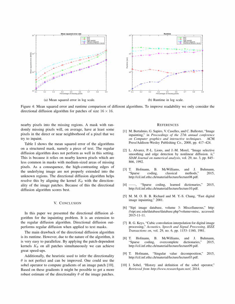
The mean squared error of the algorithms for the ran-domly generated masks are displayed in figure 4a and theruntime is displayed in figure 4b. The mean squared errorand runtime of the algorithms for the text mask is given intable I.
IV. DISCUSSION
Both the regular diffusion and the directional diffusionalgorithm show promising results. From figure 4a we seethat the regular diffusion algorithm with the Kdiamond kernelworks best on a mask with randomly missing pixels. Thiscan be explained by the fact that this algorithm diffuses
Percentage of missing pixels0.1 0.2 0.3 0.4 0.5 0.6 0.7 0.8 0.9
Mea
n sq
uare
d er
ror
(MS
E)
10 -4
10 -3
10 -2
10 -1 Mean squared error rate
DCTSVDHaar waveletDiffusion diamondDirectional diffusion 16x16
(a) Mean squared error in log scale.
Percentage of missing pixels0.1 0.2 0.3 0.4 0.5 0.6 0.7 0.8 0.9
Run
time
(sec
)
10 -1
100
101
102 Runtime
DCTSVDHaar waveletDiffusion diamondDirectional diffusion 16x16
(b) Runtime in log scale.
Figure 4: Mean squared error and runtime comparison of different algorithms. To improve readability we only consider thedirectional diffusion algorithm for patches of size 16× 16.
nearby pixels into the missing regions. A mask with ran-domly missing pixels will, on average, have at least somepixels in the direct or near neighborhood of a pixel that wetry to inpaint.
Table I shows the mean squared error of the algorithmson a structured mask, namely a piece of text. The regulardiffusion algorithm does not perform as well in this setting.This is because it relies on nearby known pixels which areless common in masks with medium-sized areas of missingpixels. As a consequence, the high-contrasting edges ofthe underlying image are not properly extended into theunknown regions. The directional diffusion algorithm helpsresolve this by aligning the kernel Kθ with the direction-ality of the image patches. Because of this the directionaldiffusion algorithm scores best.
V. CONCLUSION
In this paper we presented the directional diffusion al-gorithm for the inpainting problem. It is an extension tothe regular diffusion algorithm. Directional diffusion out-performs regular diffusion when applied to text masks.
The main drawback of the directional diffusion algorithmis its runtime. However, due to the nature of the algorithm, itis very easy to parallelize. By applying the patch-dependentkernels Kθ on all patches simultaneously we can achievegreat speed-ups.
Additionally, the heuristic used to infer the directionalityθ is not perfect and can be improved. One could use thesobel operator to compute gradients of an image patch [10].Based on these gradients it might be possible to get a morerobust estimate of the directionality θ of the image patches.
REFERENCES
[1] M. Bertalmio, G. Sapiro, V. Caselles, and C. Ballester, “Imageinpainting,” in Proceedings of the 27th annual conferenceon Computer graphics and interactive techniques. ACMPress/Addison-Wesley Publishing Co., 2000, pp. 417–424.
[2] L. Alvarez, P.-L. Lions, and J.-M. Morel, “Image selectivesmoothing and edge detection by nonlinear diffusion. ii,”SIAM Journal on numerical analysis, vol. 29, no. 3, pp. 845–866, 1992.
[3] T. Hofmann, B. McWilliams, and J. Buhmann,“Sparse coding, classical methods,” 2015,http://cil.inf.ethz.ch/material/lecture/lecture08.pdf.
[4] ——, “Sparse coding, learned dictionaries,” 2015,http://cil.inf.ethz.ch/material/lecture/lecture10.pdf.
[5] M. M. O. B. B. Richard and M. Y.-S. Chang, “Fast digitalimage inpainting,” 2001.
[6] “Sipi image database, volume 3: Miscellaneous,” http://sipi.usc.edu/database/database.php?volume=misc, accessed:2015-11-11.
[7] R. G. Keys, “Cubic convolution interpolation for digital imageprocessing,” Acoustics, Speech and Signal Processing, IEEETransactions on, vol. 29, no. 6, pp. 1153–1160, 1981.
[8] T. Hofmann, B. McWilliams, and J. Buhmann,“Sparse coding, overcomplete dictionaries,” 2015,http://cil.inf.ethz.ch/material/lecture/lecture09.pdf.
[9] T. Hofmann, “Singular value decomposition,” 2015,http://cil.inf.ethz.ch/material/lecture/lecture03.pdf.
[10] I. Sobel, “History and definition of the sobel operator,”Retrieved from http://www.researchgate.net/, 2014.


![Reaction rates for mesoscopic reaction-diffusion … rates for mesoscopic reaction-diffusion kinetics ... function reaction dynamics (GFRD) algorithm [10–12]. ... REACTION RATES](https://img.dokumen.tips/doc/110x75/5b33d2bc7f8b9ae1108d85b3/reaction-rates-for-mesoscopic-reaction-diffusion-rates-for-mesoscopic-reaction-diffusion.jpg)


![Adaptive Gradient-Based and Anisotropic Diffusion Equation ... · rithm [4], feature fusion filtering algorithm [5-7], wavelet based filtering algorithm [8-11] etc., some specific](https://img.dokumen.tips/doc/110x75/5f068e2f7e708231d4189211/adaptive-gradient-based-and-anisotropic-diffusion-equation-rithm-4-feature.jpg)