Embed Size (px)
Citation preview

ORIGINAL ARTICLE
A digraph-based expert system for non-traditionalmachining processes selection
Nilanjan Das Chakladar & Ranatosh Das &
Shankar Chakraborty
Received: 15 February 2008 /Accepted: 14 August 2008 / Published online: 30 August 2008# Springer-Verlag London Limited 2008
Abstract The presence of a number of available non-traditional machining (NTM) processes has brought out theidea of selecting the most suitable NTM process forgenerating a desired shape feature on a given work material.This paper presents a digraph-based approach to ease out theappropriate NTM process selection problem. It includes thedesign and development of an expert system that canautomate this decision-making process with the help ofgraphical user interface and visual aids. The proposedapproach employs the use of pair-wise comparison matricesto calculate the relative importance of different attributesaffecting the NTM process selection decision. Based on thecharacteristics and capabilities of the available NTMprocesses to machine the required shape feature on a givenwork material, the permanent values of the matrices relatedto those processes are computed. Finally, if some of the NTMprocesses satisfy a certain threshold value, those are short-listed as the acceptable processes for the given shape featureand work material combination. The digraph-based expertsystem not only segregates the accepted NTM processesfrom the list of the available processes but also ranks them indecreasing order of preference. It also helps the user as aresponsible guide to select the most suitable NTM process byincorporating all the possible error trapping mechanisms.This paper takes into account some new work materials,shape features and NTM processes that have not beenconsidered by the earlier researchers. It is further observedthat the developed expert system is quite flexible andversatile as the results of the cited examples totallycorroborate with those obtained by the past researchers.
Keywords Non-traditional machining process . Digraph .
Expert system . Graphical user interface . Permanentofmatrix
1 Introduction
With the continuous use and development of materials liketitanium, stainless steel, high-strength temperature-resistantalloys, fibre-reinforced composites, ceramics, refractoriesand other difficult to machine alloys having higher strength,hardness, toughness and other diverse properties, there is aneed for machine tools and processes which can accuratelyand easily machine those materials to intricate and accurateshapes. Traditional edged cutting tool machining process-es are uneconomical for such materials as the attainabledegree of accuracy and surface finish are quite poor.Machining of complex shapes in such materials bytraditional processes is still more difficult. Other higherlevel requirements like low tolerance, higher productionrate, automated data transmission, miniaturisation, etc.,cannot be achieved by the traditional metal machiningprocesses. To meet these demands, a different class ofnewer material removal processes has now emerged.These newer processes are called non-traditional in thesense that, instead of conventional cutting tools, energyin its direct form is used to remove materials from theworkpiece [1, 2]. Some of these newly developedprocesses can also machine workpieces in areas whichare inaccessible for traditional machining processes. Thesemachining processes become still more important in thearea of micro- and nano-machining. It has been observedthat, in conventional machining processes where materialis removed in the form of chips, attainment of the desiredaccuracy is a difficult task. However, such accuracy can beachieved by these non-traditional machining (NTM)
Int J Adv Manuf Technol (2009) 43:226–237DOI 10.1007/s00170-008-1713-0
N. D. Chakladar :R. Das : S. Chakraborty (*)Department of Production Engineering, Jadavpur University,Kolkata 700032 West Bengal, Indiae-mail: [email protected]
processes where the material is removed in the form ofatoms or molecules individually or in groups. Thus,effective utilisation of the capabilities of different NTMprocesses needs careful selection of the most suitableprocess for a given machining application. While selectinga NTM process to be employed, the following aspects areusually considered:
a) Physical parametersb) Properties of the work material and shape feature to be
machinedc) Process capabilityd) Economy
These aforesaid considerations make the comparison ofthe machining capabilities of different NTM processes adifficult task. An increasing shortage of experiencedexperts in the field of NTM processes creates majorhindrance in the selection of an appropriate NTM processfor a given situation. Hence, there is a need for thedevelopment of a simple scientific tool to guide the usersin taking a proper NTM process selection decision inorder to fulfil the real-time requirements of the machiningapplication.
Cogun [3, 4] developed a computer-aided selectionprocedure to aid the decision makers in selecting theNTM processes for a given part. The selection procedureuses an interactively generated 16-digit classification codeto eliminate the unsuitable combinations from considerationand rank the remaining NTM processes. Only the workmaterial and some of the process capabilities like surfacefinish, size tolerance, corner radii, taper, hole diameter, holeheight to diameter ratio and width of cut are consideredwhile selecting the best NTM process. Yurdakul and Cogun[5] proposed a multi-attribute selection procedure to helpthe manufacturing personnel in determining the suitableNTM process for a given machining application. Theselection procedure first narrows down the list of NTMprocesses to a shortlist containing only the feasibleprocesses. Then, it ranks the feasible NTM processesaccording to their suitability for a specific application.Relative weights of importance to various process selectionattributes are determined using analytic hierarchy process(AHP), whereas technique for order preference by similar-ity to ideal solution (TOPSIS) is used to rank each of thefeasible NTM processes. They developed the multi-attribute-based NTM process selection procedure taking into accounttwo work materials (ceramic and hardened 52100 steel)and only one machining operation (cylindrical throughhole drilling having L/D ratio=5.7). Seven attributes suchas tolerance (T), surface finish (SF), surface damage (SD),taper (TR), material removal rate (MRR), work material(WM) and cost (C) and some useful NTM processes areconsidered while employing the multi-attribute approach
for ranking the feasible NTM processes for a givenmachining application. Chakraborty and Dey [6] designedan AHP-based expert system with a graphical userinterface to ease out the NTM process selection procedure.The developed expert system relies on the priority valuesfor different criteria and sub-criteria, as related to aspecific NTM process selection problem. It also dependson the logic table to identify those NTM processes that liein the acceptability zone and then selects the best processhaving the highest acceptability index value. Chakrabortyand Dey [7] developed an expert system based on qualityfunction deployment for NTM process selection. A houseof quality matrix is employed for comparison of therelevant product and process characteristics, and theweights obtained for various process characteristics areutilised to estimate an overall score for each of the NTMprocesses to select the best one. Chakraborty and Dey [6,7] considered seven NTM processes [ultrasonic machining(USM), abrasive jet machining (AJM), electrochemicalmachining (ECM), electric discharge machining (EDM),electron beam machining (EBM), laser beam machining(LBM) and plasma arc machining (PAM)] from which thedeveloped systems select the most suitable process tomachine four main types of shape features (through holes,through cavities, surfacing and through cutting) on eightdifferent types of work materials. This paper incorporatesone additional NTM process, whereas the lists of workmaterials and shape features remain the same.
Graph theory and digraph models are logical andsystematic approaches used for modeling and analysingvarious kinds of systems and problems in diverse fields ofscience and technology. This paper focuses on thedevelopment of a digraph-based expert system to aid thedecision maker to select the most suitable NTM process fora given work material and shape feature combination. Itconsiders the following eight NTM processes from whichthe developed expert system selects the best one:
a) AJMb) USMc) Chemical machining (CHM)d) EBMe) LBMf) ECMg) EDMh) PAM.
2 NTM processes
In AJM process, a jet of inert gas consisting of very fineabrasive particles strikes the workpiece at a very highvelocity (200–400 m/s), resulting in material removal
Int J Adv Manuf Technol (2009) 43:226–237 227

through chipping/erosive action. When an abrasive particleimpinges on the work surface at a high velocity, theimpact causes a tiny brittle fracture and the flowing gascarries away the dislodged material. This erosive action isused for cutting, cleaning, etching, polishing and debur-ring operations of hard and brittle materials like glass,silicon, tungsten, ceramics, etc. USM, which is amechanical type of machining process used to machinehard and brittle materials (conductive and non-conduc-tive), employs a tool with high-frequency mechanicalmotion and abrasive slurry filling the gap between the tooland workpiece. CHM is a process to remove material bydissolution in a controlled manner from the workpiece bythe application of acidic or alkaline solution called asetchant. Maskants are used to cover the surface which isnot to be machined and allow the etchant not to react atthat location. Material removal occurs both in thedownward (depth of cut) and lateral (undercut) directions.In EBM process, a high-velocity stream of electronsgenerated by heating the thermo-electric cathode to a hightemperature strikes the workpiece, thus transforming thekinetic energy liberated into heat and a very small amountof light energy while removing material from the worksurface by melting and vaporisation. A tremendousamount of energy is released in lasers due to collision ofoscillating high-energy-level atoms with electro-magneticwaves with resonant frequency. When this phenomenon isutilised for melting and vaporisation of the material fromthe workpiece surface, the process is called as LBM. InECM, electrical energy is transported through metals byconduction of electrical charges from one place to another.As opposed to metallic conduction, where only electronsare the charge carriers, salt solutions also conductelectrical energy by the migration of ions in the medium.In ECM process, a single tool can be used to machine alarge number of workpieces without any loss in its shapeand size. In EDM process, whenever sparking takes placebetween two electrical contacts, a small amount ofmaterial is removed from both contacts. It is observedthat sparks with short duration and high frequency areuseful for efficient machining within a small area whensubmerged in a dielectric. In this process, the spark energyis capable of partially melting and vaporising materialfrom a localised area on both the electrode (workpiece)and tool. Plasma, which is a glowing, ionised gasresulting from heating of a material to extremely hightemperature (33,000°C), is composed of free electronsdissociated from the main gas atoms. When such a hightemperature source reacts with the work material, thematerial melts and vaporises and, finally, is cut intopieces. The main mechanisms of material removal areheating, melting and removal of molten metal by blastingaction of the plasma jet [8].
3 Digraph method
The concept of digraph elucidates the easy understandabil-ity and acceptance of the optimal criterion under investiga-tion. Beginning from AHP to relationship diagram, thesemethods are found to be troublesome from the viewpoint ofcomputational ability. Hence, the emergence of digraph andpermanent of matrices come into picture. A digraphconsists of a set of nodes N={ni} (i=1, 2,…, M) and a setof directed edges E={eij}. A node ni represents ith selectioncriterion/attribute and edges represent the relative impor-tance among the attributes. The total of nodes, M, is equalto the number of selection criteria considered. If a node ihas relative importance over another node j in the selectionprocess, a directed edge or arrow is drawn from node i tonode j(eij). If j is having relative importance over i, then adirected edge or arrow is drawn from node j to node i(eji).The digraph basically depicts the graphical representationof the interdependence between various decision attributestaken two at a time and their relative importance for quickvisual perception [9–15]. As the number of nodes and theirinterrelations increases, the digraph becomes complex. Insuch a case, simple analysis of the digraph is expected to bedifficult and complex. To overcome this problem, thedigraph is usually represented in a matrix form [16]. Matrixrepresentation of a digraph gives one-to-one representation,taking all the attributes (Ai) and their relative importance(aij) into account. The matrix B for a digraph can berepresented as:
B ¼
Ai a12 a13 . . . . . . . . . a1Ma21 A2 a23 . . . . . . . . . a2Ma31 a32 A3 . . . . . . . . . a3M. . . . . . . . . . . . . . . . . . . . .. . . . . . . . . . . . . . . . . . . . .. . . . . . . . . . . . . . . . . . . . .aM1 aM2 aM3 . . . . . . . . . AM
2666666664
3777777775
ð1Þ
where Ai is the value of the ith attribute represented by nodeni and aij is the relative importance of the ith attribute overthe jth one represented by the edge eij. The permanent ofthe matrix B can be defined as a function which leads to abetter visualisation of digraph theory. In the expression forpermanent of the matrix, as no negative sign appears, noinformation is lost. This permanent function is thedeterminant of a matrix, considering all the terms aspositive.
4 Digraph for NTM process selection
An effective selection procedure requires the considerationof various quantitative and qualitative factors. The objective
228 Int J Adv Manuf Technol (2009) 43:226–237

of a NTM process selection approach is to identify theNTM process selection attributes/criteria and obtain themost appropriate combination of those attributes in light ofreal-time requirements. A NTM process selection attributecan be defined as a factor that governs the selectionprocedure of a NTM process for a given machiningapplication. The NTM process selection criteria basicallyinclude workpiece material, power consumption, cost,process capability attributes like MRR, tolerance, surfacefinish, surface damage, corner radii, taper, hole diameter,depth/diameter ratio (slenderness ratio) for cylindricalholes, depth/width ratio (aspect ratio) for cavities andpockets, width of cut, heat affected zone, exterior andinterior profiles [15], etc. Almost all the attributes mayaffect the machining performance of the NTM processes tosome extent, but only six most significant attributes, suchas tolerance and surface finish (TSF), MRR, powerrequirement (PR), C, shape feature (F) and work materialtype (M), are incorporated in the digraph-based NTMprocess selection procedure. Considering all the processattributes in the digraph and matrix method will also causethe computation of permanent values of the matrices to be adifficult and tedious task [17]. These six attributes arechosen in such a way that they will cover all the other non-dominating attributes as sub-attributes [6]. The NTMprocess selection digraph is developed based on these sixattributes, as shown in Fig. 1.
The NTM process selection digraph exhibits the NTMprocess selection attributes and their interrelationship. Assix NTM process selection attributes are considered, thereare six nodes in the developed digraph. MRR is relativelymore important than PR in NTM process selection.However, PR is also important even though less important
than MRR. Thus the relative importance exists betweenthese two attributes in both directions. Similarly, therelative importance can also be represented between theother attributes. The NTM process selection digraph can beexpressed in a matrix form, as given below:
D ¼
TSF MRR PR C F MTSF A1 a12 a13 a14 a15 a16MRR a21 A2 a23 a24 a25 a26PR a31 a32 A3 a34 a35 a36C a41 a42 a43 A4 a45 a46F a51 a52 a53 a54 A5 a56M a61 a62 a63 a64 a65 A6
2666666664
3777777775
ð2Þ
The NTM process selection function for matrix Eq. 2can be written [13] as follows:
per Dð Þ ¼ Q6i¼1
Ai þP5i¼1
P6j¼iþ1
P3k¼1
P4l¼kþ1
P5m¼lþ1
P6n¼mþ1
aijaji� �
AkAlAmAn
þP4
i¼1
P5j¼iþ1
P6k¼jþ1
P4l¼1
P5m¼lþ1
P6n¼mþ1
aijajkaki þ aikakjaji� �
AlAmAn
þ P3i¼1
P6j¼iþ1
P5k¼jþ1
P6l¼iþ2
P5m¼lþ1
P6n¼mþ1
aijaji� �
aklalkð ÞAmAn
þP3
i¼1
P5j¼iþ1
P6k¼iþ1
P6l¼jþ1
P5m¼1
P6n¼mþ1
aijajkaklali þ ailalkakjaji� �
AmAnÞ
þ P4i¼1
P5j¼iþ1
P6k¼jþ1
P5l¼1
P6m¼lþ1
P6n¼1
aijajkaki þ aikakjaji� �
almamlð ÞAn
þP2
i¼1
P5j¼iþ1
P6k¼iþ1
P6l¼iþ1
P6m¼jþ1
P6n¼1
aijajkaklalmami þ aimamlalkakjaji� �
AnÞ
þ P3i¼1
P5j¼iþ1
P6k¼iþ1
P6l¼jþ1
P5m¼1
P6n¼mþ1
aijajkaklali þ ailalkakjaji� �
� amnanmð ÞþP
1
i¼1
P5j¼iþ1
P6k¼jþ1
P4l¼1
P5m¼lþ1
P6n¼mþ1
aijajkaki þ aikakjaji� �
� almamnanl þ alnanmamlð ÞþP
1
i¼1
P6j¼iþ1
P3k¼iþ1
P6l¼iþ2
P5m¼kþ1
P6n¼kþ2
aijaji� �
aklalkð Þ amnanmð Þ
þP1
i¼1
P5j¼iþ1
P6k¼iþ1
P6l¼iþ1
P6m¼iþ1
P6n¼jþ1
�ðaijajkaklalmamnani þ ainanmamlalkakjajiÞÞð3Þ
Equation 3 is the complete expression for the consideredNTM process selection problem, as it considers thepresence of all the attributes and possible relative impor-tance between the attributes. The terms in the aboveexpression are the sets of distinct diagonal elements andloops of off-diagonal elements of different sizes.
5 Digraph-based expert system for NTM processselection
Lack of knowledge regarding the capabilities of differentNTM processes, uncertainties related to various costFig. 1 NTM process selection digraph
Int J Adv Manuf Technol (2009) 43:226–237 229

elements while operating those NTM processes, complexprocess characteristics and shortage of information regard-ing the applicabilities of the NTM processes often make theselection of the most suitable NTM process for a givenwork material and shape feature combination a challengingtask. An expert system is a computer programme intendedto embody the knowledge and ability of an expert in acertain domain. The primary goal of an expert system is tomake expertise available to the decision makers who needanswers quickly. There is never enough expertise to goaround—certainly it is not always available at the rightplace and the right time. Expert knowledge is a combina-tion of a theoretical understanding of the problem and acollection of heuristic problem-solving rules that experiencehas shown to be effective in the domain. Expert systems areconstructed by obtaining this knowledge from a humanexpert and coding it into a form that a computer may applyto similar problems. This reliance on the knowledge of ahuman domain expert for the system’s problem solvingstrategies is a major feature of expert system. The basiccomponents of an expert system are a knowledge base (KB)and an inference engine. The information to be stored in theKB is obtained by interviewing people who are experts inthe area in question. The database related to the applicabil-ity of different NTM processes to machine various shapefeatures on different work materials is retrieved using theinference engine, which enables us to draw deductionsregarding the selection of the most appropriate NTMprocess for a given application.
The developed digraph-based expert system for NTMprocess selection considers six different attributes thatdirectly influence the NTM process selection problem.Being an expert system, it acts as a decision aid to select themost suitable NTM process for a given work material andshape feature combination. The NTM process selection isbased on the construction of three matrices, i.e. (a)comparison matrix between different selection attributes,(b) normalised matrix and (c) final selection matrix. Thefeatures of a digraph include the concept of the permanentof a matrix that makes the comparison between variousattributes easier and helps to clearly analyse the attributesaffecting the NTM process selection decision. Theseattributes can be related to the following NTM processcharacteristics that are taken into account while fulfiling therequirements of the manufacturing personnel.
(a) Application:
1. Material application: It is mainly concerned withhow easily a specific work material can bemachined using a particular NTM process.
2. Shape application: This is the capability of a NTMprocess to generate a specific shape feature on agiven work material that it can machine.
(b) TSF: It relates to the capability of a NTM process,stating how closely the process can achieve therequired TSF on the work material.
(c) MRR: It is the most important criterion leading to thefact that higher MRR leads to lower machining time,and the effectiveness of a NTM process is usuallymeasured in terms of MRR.
(d) PR: It deals with the power consumption of themachining set-up for a particular NTM process.
(e) Cost: It is concerned with the initial investment andacquisition cost needed to install a NTM process-basedmachining system for a given application.
These NTM process characteristics are assumed to beindependent of each other to avoid repetition in analysis.
The NTM process selection matrix includes both thequantitative and qualitative attributes. The value of Ai can beobtained from specified or experimental data. When quanti-tative values of various attributes are available, the assignedvalues are estimated by vij, where vi is the measure of theattribute for the ith alternative and vj is the measure of theattribute for jth alternative, which has the highest measureamong the considered alternatives [11]. This ratio isapplicable only for beneficial attributes like MRR. Non-
Table 2 Pair-wise comparison matrix for the NTM process selectionattributes
Attribute TSF MRR PR C F M
TSF – 0.590 0.865 0.665 0.865 0.865MRR 0.410 – 0.745 0.590 0.745 0.865PR 0.135 0.255 – 0.335 0.665 0.865C 0.335 0.410 0.665 – 0.745 0.665F 0.135 0.255 0.335 0.255 – 0.745M 0.135 0.135 0.135 0.335 0.255 –
Table 1 Relative importance of the NTM process selection attributes
Class description Relativeimportance (aij)
One attribute is exceptionally less important thanthe other
0.045
One attribute is extremely less important 0.135One attribute is very less important 0.255One attribute is less important 0.335One attribute is slightly less important 0.410Two attributes are equally important 0.500One attribute is slightly more important 0.590One attribute is more important 0.665One attribute is much more important 0.745One attribute is extremely more important 0.865One attribute is exceptionally more importantthan the other
0.955
230 Int J Adv Manuf Technol (2009) 43:226–237
beneficial attributes, such as PR, cost and TSF, are thosewhose lower measures are desirable and the normalised valuesassigned to the alternatives are calculated as vji. If quantitativevalues are unavailable, a ranked value judgment on a scalecan be employed. In this NTM process selection procedure, afive-point scale is adopted for judging the performance of thealternative processes with respect to cost, shape feature and
work material type. Sometimes, a ranked value judgment ona fuzzy conversion scale is also used. Rao [13] considered an11-point scale for calculating the flexible manufacturingsystem selection index, as given in Table 1. The same scaleis also employed here for pair-wise comparing the NTMprocess selection attributes. Once a qualitative attribute isrepresented on a scale, then the normalised values of the
Table 3 Quantitative values of different NTM process selectionattributes for example 1
NTM process TSF (μm) MRR (mm3/min) PR (kW) C F M
AJM 2.5 0.8 0.22 1 1 4USM 1.0 300 2.4 2 1 3CHM 3.0 15 0.4 3 4 5EBM 2.5 1.6 0.2 4 4 4LBM 2.0 0.1 1.4 3 5 4ECM 3.0 1,500 100 5 1 4EDM 3.5 800 2.7 3 1 4PAM 5.0 75,000 50 1 1 5
Table 4 Normalised values of the attributes for example 1
NTM process TSF MRR PR C F M
AJM 0.4000 0.000010 0.9091 1.0000 0.2000 0.8000USM 1.0000 0.004000 0.0833 0.5000 0.2000 0.6000CHM 0.3333 0.000200 0.5000 0.3333 0.8000 1.0000EBM 0.4000 0.000020 1.0000 0.2500 0.8000 0.8000LBM 0.5000 0.000001 0.1428 0.3333 1.0000 0.8000ECM 0. 3333 0.020000 0.0020 0.2000 0.2000 0.8000EDM 0.2857 0.010670 0.0741 0.3333 0.2000 0.8000PAM 0.2000 1.000000 0.0040 1.0000 0.2000 1.0000
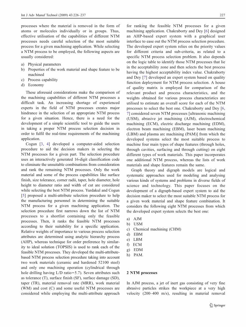
Fig. 2 Home window of the expert system
Int J Adv Manuf Technol (2009) 43:226–237 231

attribute assigned for different alternatives can be determinedin the same way as that for the quantitative attributes. It isworth mentioning here that any scale for Ai and aij can bechosen. As these are relative scales, the final ranking will notchange. Based on the ranked values, as shown in Table 1, thepair-wise comparison matrix exhibiting the relative impor-tance of different NTM process selection attributes isconstructed, as given in Table 2.
In this digraph-based approach, the following materialsare taken into account that can be machined using theconsidered NTM processes:
(a) Aluminium(b) Steel(c) Super alloys(d) Titanium
Fig. 3 Graphical output for example 1
Table 5 Permanent values related to the NTM processes for example 1
NTM process Permanent of matrix Average
AJM 5.5608 4.6450USM 4.1233CHM 5.2072EBM 5.7866LBM 4.7814ECM 3.0673EDM 3.2183PAM 5.4149
Table 6 NTM process selection attributes for example 2
NTM process TSF (μm) MRR (mm3/min) PR (kW) C F M
AJM 2.5 0.8 0.22 1 1 4USM 1.0 300 2.4 2 1 4CHM 3.0 15 0.4 3 1 4EBM 2.5 1.6 0.2 4 4 4LBM 2.0 0.1 1.4 3 4 4ECM 3.0 1,500 100 5 5 4EDM 3.5 800 2.7 3 1 5PAM 5.0 75,000 50 1 5 4
232 Int J Adv Manuf Technol (2009) 43:226–237
(e) Refractories(f) Plastics(g) Ceramics(h) Glass
Again, the following shape features are considered thatcan be generated by the available NTM processes:
(a) Holes
1. Precision2. Standard with L/D ratio <203. Standard with L/D ratio >20
(b) Through cavities
1. Precision2. Standard
(c) Surfacing
1. Double contouring2. Surface of revolution
(d) Through cutting
1. Shallow2. Deep
In order to select the most appropriate NTM process fora given material and shape feature combination, Eq. 3, i.e.the permanent of the matrix, is to be solved, substituting thevalues of Ai and aij. The NTM process having the highestpermanent of matrix value is the best choice for the givenapplication.
6 Inputs and outputs of the expert system
In this paper, an expert system is designed and developed inVisual Basic 6.0 at the front end, with Microsoft OfficeExcel 2003 at the back to store the database, while utilisingSP6 for including Microsoft Chart Control 2.0 to displaythe graphical outputs. The initial input window of thedeveloped expert system is exhibited in Fig. 2. The
graphical user interface of the expert system helpsthe user to avoid all the multifarious calculations relatedto normalisation and permanent values of the matrices.The expert system displays those permanent values of thematrices while selecting the most suitable NTM processfor a given application. Its home window has fourfunctional buttons, i.e. ‘COMPUTE’, ‘PRINT’, ‘REFRESH’and ‘EXIT’ in the left and a picture box in the right to portraythe outputs graphically. This window also has the options forselecting the work material type and shape feature to begenerated from the pop-downmenus. After choosing the workmaterial and shape feature, pressing of the ‘COMPUTE’button calculates the permanent values of the matrices relatedto different NTM processes and lists those NTM processesthat are suitable for the given combination. The hardcopy ofthe computed results can be obtained by clicking the ‘PRINT’button. The ‘REFRESH’ button allows the user to input a newset of work material and shape feature combination aftergetting the results from the previous analysis. The ‘EXIT’button closes the home window of the expert system,returning back to the Windows operating system. All thenecessary error trapping messages are provided in the expertsystem for ease of the users.
6.1 Example 1
In this example, aluminium is chosen as the workmaterial and precision holes are to be generated on it.At first, to select the most suitable NTM process formachining of precision holes on aluminium, the capa-bilities of different NTM processes with respect to sixattributes are considered and compared [2]. Among theseNTM process selection attributes, TSF, MRR and PR arebased on absolute scales, whereas C, F and M are assignedwith rank judgment scales. MRR, F and M are thebeneficial attributes, where higher values are desirable.On the other hand, TSF, PR and C are non-beneficialattributes, and for these attributes, lower values aredesirable. The quantitative values of the NTM process
Table 8 Permanent values for example 2
NTM process Permanent of matrix Average
AJM 5.5608 4.8015USM 4.4425CHM 3.8728EBM 5.7866LBM 4.4879ECM 4.0360EDM 3.4398PAM 6.7852
Table 7 Normalised NTM process selection attributes for example 2
NTMprocess
TSF MRR (mm3/min)
PR C F M
AJM 0.4000 0.000010 0.9091 1.0000 0.2000 0.8000USM 1.0000 0.004000 0.0833 0.5000 0.2000 0.8000CHM 0.3333 0.000200 0.5000 0.3333 0.2000 0.8000EBM 0.4000 0.000020 1.0000 0.2500 0.8000 0.8000LBM 0.5000 0.000001 0.1428 0.3333 0.8000 0.8000ECM 0.3333 0.020000 0.0020 0.2000 1.0000 0.8000EDM 0.2857 0.010670 0.0741 0.3333 0.2000 1.0000PAM 0.2000 1.000000 0.0040 1.0000 1.0000 0.8000
Int J Adv Manuf Technol (2009) 43:226–237 233

selection attributes are given in Table 3. These values arepurely based on the experimental results and expertopinions [1, 2]. Table 4 exhibits the normalised values ofthese attributes for different NTM processes. Dependingon the capability of a particular NTM process to machine adesired shape feature on a given work material, the entriesof the last two columns of Table 3 usually need to bechanged. The developed expert system automatically takescare of those values from its KB and constructs the finalNTM process selection matrix from which the permanentvalue related to each NTM process is computed. Table 5gives the permanent values of the matrices for differentNTM processes.
When the user completes inputting the work materialtype and shape feature to be machined on that material, he/she needs to press the ‘COMPUTE’ button to obtain thecomputational results and related graphical outputs. In this
example, the most suitable NTM process is EBM. Theexpert system also lists the other acceptable NTM processes(AJM, PAM, CHM and LBM) in descending order ofpreference. The selection of the acceptable NTM processesfor the given situation is entirely based on the calculation ofthe permanent values of matrices associated with the NTMprocesses. The average permanent value of the matrices iscalculated as 4.6450. The NTM processes with permanentof matrix value greater than the average are considered tobe acceptable for machining of precision holes on alumin-ium. The graphical output from the expert system isexhibited in Fig. 3.
6.2 Example 2
Here, a deep through cutting operation is to be performedon titanium. The quantitative values of the NTM process
Fig. 4 Output for example 2
234 Int J Adv Manuf Technol (2009) 43:226–237
selection attributes and their normalised values are given inTables 6 and 7, respectively. Based on the computedpermanent of matrix values for different NTM processes,the expert system selects PAM as the most appropriateNTM process. Electron beam and AJM processes can alsogenerate deep through cut on titanium, but having lowerpriorities than PAM. Table 8 gives the values of thepermanent of matrices based on which the NTM processselection decision is made. Figure 4 shows the graphicaloutput of the expert system.
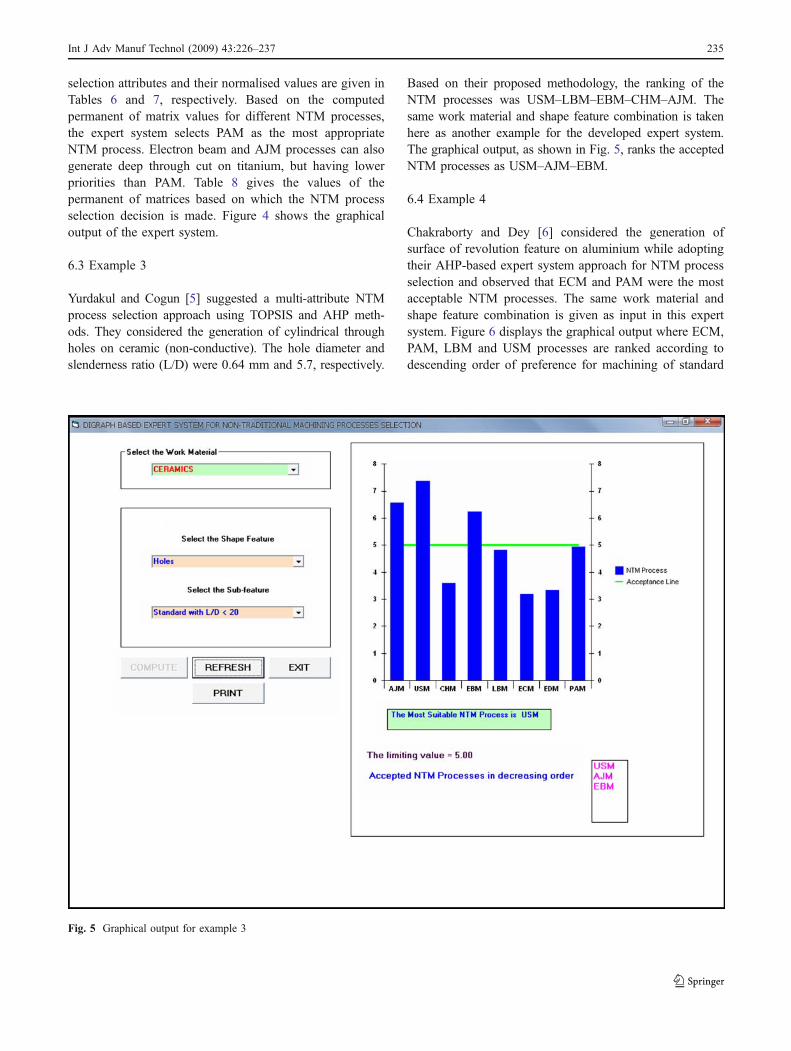
6.3 Example 3
Yurdakul and Cogun [5] suggested a multi-attribute NTMprocess selection approach using TOPSIS and AHP meth-ods. They considered the generation of cylindrical throughholes on ceramic (non-conductive). The hole diameter andslenderness ratio (L/D) were 0.64 mm and 5.7, respectively.
Based on their proposed methodology, the ranking of theNTM processes was USM–LBM–EBM–CHM–AJM. Thesame work material and shape feature combination is takenhere as another example for the developed expert system.The graphical output, as shown in Fig. 5, ranks the acceptedNTM processes as USM–AJM–EBM.
6.4 Example 4
Chakraborty and Dey [6] considered the generation ofsurface of revolution feature on aluminium while adoptingtheir AHP-based expert system approach for NTM processselection and observed that ECM and PAM were the mostacceptable NTM processes. The same work material andshape feature combination is given as input in this expertsystem. Figure 6 displays the graphical output where ECM,PAM, LBM and USM processes are ranked according todescending order of preference for machining of standard
Fig. 5 Graphical output for example 3
Int J Adv Manuf Technol (2009) 43:226–237 235

through holes on titanium. It is observed that all the resultsobtained from the expert system are more or less the sameas those derived by the past researchers, which show thegreater acceptability and applicability of the developedexpert system while selecting the NTM processes in a real-time manufacturing environment.
7 Conclusions
A methodology based on the development of a digraph-based expert system is proposed which helps in selecting themost suitable NTM process from a large number of availablealternative NTM processes for machining of a shape featureon a given work material. The proposed system identifiesand considers different NTM process selection attributes andtheir interrelations for a given NTM process selectionproblem. It can simultaneously take into account any number
of quantitative and qualitative NTM process selectionattributes and offer a more objective and simple NTMprocess selection approach. The comparative study betweenthe alternative NTM processes aids in developing anddeploying the available technologies by focusing into theprocess characteristics that are not present in the consideredNTM processes in terms of their capabilities to machine aspecific shape feature on a given work material. Anotheradvantage of this expert system is that it does not requirehaving any in-depth technological knowledge regarding theapplicability of the NTM processes. Moreover, it relieves theuser from committing any error while taking the decisionregarding the selection of the most suitable NTM process fora given machining application. This expert system can beemployed as a benchmark to select the NTM processes fordifferent machining applications. It can be made moredynamic and versatile by including all the NTM processes,shape features and materials yet to come in the near future.
Fig. 6 Graphical output for example 4
236 Int J Adv Manuf Technol (2009) 43:226–237

References
1. Jain VK (2005) Advanced machining processes. Allied, New Delhi2. Pandey PC, Shan HS (1981) Modern machining processes. Tata
McGraw-Hill, New Delhi3. Cogun C (1993) Computer-aided system for selection of nontra-
ditional machining operations. Comput Ind 22(2):169–179.doi:10.1016/0166-3615(93)90063-7
4. Cogun C (1994) Computer aided preliminary selection of non-traditional machining processes. Int J Mach Tools Manuf 34:315–326. doi:10.1016/0890-6955(94)90002-7
5. Yurdakul M, Cogun C (2003) Development of a multi-attributeselection procedure for non-traditional machining processes. ProcIMechE J Eng Manuf 217:993–1009
6. Chakroborty S, Dey S (2006) Design of an analytic-hierarchy-process-based expert system for non-traditional machining processselection. Int J Adv Manuf Technol 31(5–6):490–500.doi:10.1007/s00170-005-0216-5
7. Chakroborty S, Dey S (2007) QFD-based expert system for non-traditional machining processes selection. Expert Syst Appl 32(4):1208–1217. doi:10.1016/j.eswa.2006.02.010
8. McGeough JA (1988) Advanced methods of machining. Chapmanand Hall, London
9. Rao VR, Gandhi OP (2002) Digraph and matrix methods for themachinability evaluation of work materials. Int J Mach ToolsManuf 42(3):321–330. doi:10.1016/S0890-6955(01)00133-X
10. Rao VR, Gandhi OP (2002) Failure cause analysis of machinetools using digraph and matrix methods. Int J Mach Tools Manuf42(4):521–528. doi:10.1016/S0890-6955(01)00135-3
11. Rao VR, Padmanabhan KK (2006) Selection, identification andcomparison of industrial robots using digraph and matrix methods.Robot Comput-Integr Manuf 22(4):373–383. doi:10.1016/j.rcim.2005.08.003
12. Rao VR (2006) A material selection model using graph theory andmatrix methods. Mater Sci Eng A 431(1–2):248–255.doi:10.1016/j.msea.2006.06.006
13. Rao VR (2006) A decision-making framework model forevaluating flexible manufacturing systems using digraph andmatrix methods. Int J Adv Manuf Technol 30(11–12):1101–1110.doi:10.1007/s00170-005-0150-6
14. Rao VR, Padmanabhan KK (2007) Rapid prototyping processselection using graph theory and matrix approach. J MaterProcess Technol 194:81–88. doi:10.1016/j.jmatprotec.2007.04.003
15. Rao VR (2006) Selection of a non-traditional machining processusing digraph and matrix method. In: Proceedings of the 1stInternational and 22nd AIMTDR Conference, IIT, Roorkee, 21–23 December 2006, pp 979–983
16. Jense JB, Gutin G (2000) Digraph theory, algorithms andapplications. Springer, London
17. Rao VR (2007) Decision making in the manufacturing environ-ment using graph theory and fuzzy multiple attribute decisionmaking methods. Springer, London
Int J Adv Manuf Technol (2009) 43:226–237 237