Embed Size (px)
Citation preview

SANDIA REPORT
SAND2004-6441 Unlimited Release Printed December 2004 A Digital Accelerometer Array Utilizing Suprathreshold Stochastic Resonance for Detection of Sub-Brownian Noise Floor Accelerations
Roy H. Olson III and Dustin W. Carr
Prepared by Sandia National Laboratories Albuquerque, New Mexico 87185 and Livermore, California 94550 Sandia is a multiprogram laboratory operated by Sandia Corporation, a Lockheed Martin Company, for the United States Department of Energy’s National Nuclear Security Administration under Contract DE-AC04-94AL85000. Approved for public release; further dissemination unlimited.

Issued by Sandia National Laboratories, operated for the United States Department of Energy by Sandia Corporation.
NOTICE: This report was prepared as an account of work sponsored by an agency of the United States Government. Neither the United States Government, nor any agency thereof, nor any of their employees, nor any of their contractors, subcontractors, or their employees, make any warranty, express or implied, or assume any legal liability or responsibility for the accuracy, completeness, or usefulness of any information, apparatus, product, or process disclosed, or represent that its use would not infringe privately owned rights. Reference herein to any specific commercial product, process, or service by trade name, trademark, manufacturer, or otherwise, does not necessarily constitute or imply its endorsement, recommendation, or favoring by the United States Government, any agency thereof, or any of their contractors or subcontractors. The views and opinions expressed herein do not necessarily state or reflect those of the United States Government, any agency thereof, or any of their contractors. Printed in the United States of America. This report has been reproduced directly from the best available copy. Available to DOE and DOE contractors from
U.S. Department of Energy Office of Scientific and Technical Information P.O. Box 62 Oak Ridge, TN 37831 Telephone: (865)576-8401 Facsimile: (865)576-5728 E-Mail: [email protected] Online ordering: http://www.osti.gov/bridge
Available to the public from
U.S. Department of Commerce National Technical Information Service 5285 Port Royal Rd Springfield, VA 22161 Telephone: (800)553-6847 Facsimile: (703)605-6900 E-Mail: [email protected] Online order: http://www.ntis.gov/help/ordermethods.asp?loc=7-4-0#online
2

SAND2004-6441 Unlimited Release
Printed December 2004
A Digital Accelerometer Array Utilizing Suprathreshold Stochastic Resonance for Detection of Sub-Brownian Noise Floor Accelerations
Roy H. Olsson I11 and Dustin W. Carr MEMS Device Technologies
Sandia National Laboratories P.O. Box 5800
Albuquerque, New Mexico 87185-1080
Abstract
The goal of this LDRD project was to evaluate the possibilities of utilizing Stochastic resonance in micromechanical sensor systems as a means for increasing signal to noise for physical sensors. A careful study of this field reveals that in the case of a single sensing element, stochastic resonance offers no real advantage. We have, however, identified a system that can utilize very similar concepts to stochastic resonance in order to achieve an arrayed sensor system that could be superior to existing technologies in the field of inertial sensors, and could offer a very low power technique for achieving navigation grade inertial measurement units.
3

INTENTIONALLY LEFT BLANK
4

State of the art micromachined accelerometer systems have achieved noise floors of 1.6pgldHz for frequencies above lkHz [ 11. The noise performance of these accelerometer microsystems is dominated, particularly at low frequencies, by the electronic circuits used to interface to the sensor. For a given bandwidth, the sensitivity of an accelerometer can be improved by increasing the mass, where the Brownian noise floor of the device is proportional to l/dm and m is the mass. As in the example above, this technique limits when the circuit noise floor is reached, which is particularly detrimental at low frequencies where ]&noise is dominant. The following presents a technique for detection of sub-Brownian noise floor accelerations using arrays of digital accelerometers. Quantizing the signal in the mechanical domain eliminates the noise floor limitations imposed by the readout circuitry and allows detection of sub 5OngldHz accelerations. In particular, the low frequency performance is not limited by circuit 1 4 noise. The small size, low power consumption, and superior low frequency performance of digital accelerometer arrays makes them particularly suited to applications such as distributed seismology.
A surface micromachined accelerometer is shown in fig. 1, where the spring constant can be controlled via the drive electrodes. Typically, the noise floor is determined by the minimum detectable displacement of the proof mass which can be sensed capacitively, optically, using piezoresistors, or by other means. In a digital accelerometer, if the input acceleration plus noise is below a specified threshold, then the output of the accelerometer is a logic 0. If the acceleration plus noise exceeds the threshold, the output is either a logic 1 or -1 depending on the direction of the acceleration. The threshold levels can be controlled via a dc voltage between the drive electrodes and the proof mass shown in fig. 1. A single digital accelerometer thus achieves a resolution of 1.58bits or a SNR of 4.77dB. A block diagram describing this system is shown in fig. 2. The threshold setting feedback voltage is applied periodically here, effectively implementing a 1.58bit track and latch comparator.
While a single digital accelerometer may not seem to be of much use (accept in g- switch applications such as package monitoring and other shock thresholding devices), an array of these accelerometers is practically capable of quantizing sub-Brownian noise floor accelerations to 8bits of resolution or a SNR of 24dB using 33,000 parallel devices. Supratheshold stochastic resonance [2,3] is used here to detect signals that would otherwise be buried in the noise. Consider the array of digital accelerometers shown in fig. 3, where the noise of each device is uncorrelated. If the input is noiseless, Anoise = 0, then all devices switch in unison and the resolution is 1.58bits regardless of the number of devices. Noise serves to distribute the thresholds, thus increasing the bits of resolution. For a large number of devices, N, thresholds near *(omm)/3, and an input signal-to-noise ratio near unity [3], the information can be expressed as [2]
I(bits) = 0.510g2(2N+l)
where om, is the total variance of the input signal plus the Brownian noise of a single accelerometer. For a lbit digital accelerometer, increasing the number of devices by a
5

factor N has the same effect on the noise floor as increasing the total mass of a traditional accelerometer [ 11 by a factor of N, which is not surprising. The advantage here is that the signal is quantized in the mechanical domain and thus is immune to circuit noise. While N readout circuits are necessary, the power consumption and complexity of these circuits is greatly reduced because the noise of these circuits does not affect the overall SNR and digital circuits can be used. As shown in fig. 1, the dimensions of a single accelerometer can be quite small, easily allowing the integration of tens of thousands of such devices. The yield, reliability and reproducibility of massively parallel accelerometer microsystems will also be superior to traditional micromachined accelerometers as the failure or degradation of one digital accelerometer does not significantly affect the performance of the overall system.
A simple example of a digital accelerometer is shown along with readout circuitry in fig. 4. The threshold of the accelerometer is controlled via the pulsed voltage on the proof mass. Because of the nonlinear voltage to displacement equation governing the location of the proof mass with respect to the fixed readout electrodes, the device will sharply pull-in to one of the fixed electrodes if the input acceleration plus the Brownian noise of the device exceeds the threshold. This is subsequently sensed by the inverters and a subtraction of the two inverter outputs yields a 1.58bit digital signal. Notice that low noise readout circuits are not necessary and that the signal is already quantized, negating the need for analog-to-digital converters following the readout circuitry. The majority of the power dissipated is the energy necessary to charge and discharge the capacitance of the fixed electrodes, which is equal to
P(watts) = 2/3Cf12
where Vis the bias voltage used to control the thresholds, C is the capacitance associated with one of the fixed electrodes, andfis the data acquisition rate in Hz. Since the signal is uniformly distributed and the thresholds are at * d 3 , the output only latches 2/3 of the time. It is interesting to note that the power consumption decreases linearly with the maximum signal frequency of interest. This is not the case is traditional accelerometers. In fact, detecting accelerations below 1kHz requires more power because the Iynoise contributions of the readout circuitry must be reduced. A typical 8-bit accelerometer system requiring 33,000 devices, operating at 5 volts, with a capacitance per device of 1pF and a bandwidth from DC to 1kHz would consume 0.55mW of power. This reduces to 550nW if the maximum signal frequency of interest is lHz, which is in the range of current power scavenging technology. Other readout techniques are also possible. By combining the deformable optical grating structures reported in [5,6] with a CCD or other dense imager, millions of these accelerometers may be able to be operated in parallel. Given that 5Megapixel CCDs are now available, a resolution of nearly12bits or a SNR of 36dB may be achievable.
6
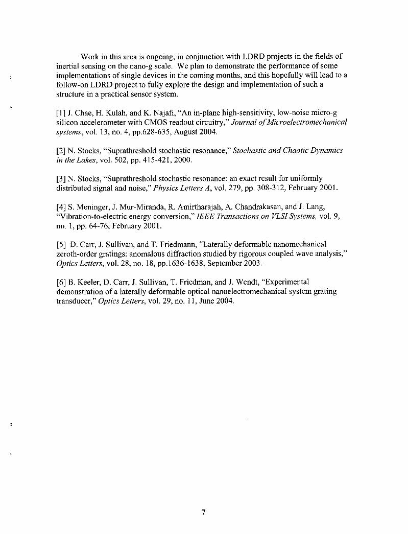
Work in this area is ongoing, in conjunction with LDRD projects in the fields of inertial sensing on the nano-g scale. We plan to demonstrate the performance of some implementations of single devices in the coming months, and this hopefully will lead to a follow-on LDRD project to fully explore the design and implementation of such a structure in a practical sensor system.
[ 11 J. Chae, H. Kulah, and IS. Najafi, “An in-plane high-sensitivity, low-noise micro-g silicon accelerometer with CMOS readout circuitry,” Journal of Microelectromechanical systems, vol. 13, no. 4, pp.628-635, August 2004.
[2] N. Stocks, “Suprathreshold stochastic resonance,” Stochastic and Chaotic Dynamics in the Lakes, vol. 502, pp. 415-421,2000.
[3] N. Stocks, “Suprathreshold stochastic resonance: an exact result for uniformly distributed signal and noise,” Physics Letters A , vol. 279, pp. 308-3 12, February 2001 I
[4] S. Meninger, J. Mur-Miranda, R. Amirtharajah, A. Chandrakasan, and J. Lang, “Vibration-to-electric energy conversion,” IEEE Transactions on VLSI Systems, vol. 9, no. 1, pp. 64-76, February 2001.
[5] D. Carr, J. Sullivan, and T. Friedmann, “Laterally deformable nanomechanical zeroth-order gratings: anomalous diffraction studied by rigorous coupled wave analysis,” Optics Letters, vol. 28, no. 18, pp.1636-1638, September 2003.
[6] B. Keeler, D. Can, J. Sullivan, T. Friedman, and J. Wendt, “Experimental demonstration of a laterally deformable optical nanoelectromechanical system grating transducer,” Optics Letters, vol. 29, no. 1 1 , June 2004.
,
7

Figure 1: Accelerometer using the laterally deformable optical gratings detailed in [5,6]
Mechanical Track and Latch Comparator
- rorce 1 pormon
me m posmon 7 M s2+D
tranner Ftn
CM N015e
Figure 2: Block diagram including noise sources of the digital track and latch 1.58bit comparator.
8

+ /) +"
A n m e
Input Acceleration
In Digital
Accel(1)
'ff 'noise
In Digital
Accel(2) Thresh Out
w *noise Threshold .I
In Dig ita1
Accel(N) Thresh Out
Figure 3: Suprathreshold stochastic resonance digital accelerometer array block diagram.
Fixed
Figure 4: An example implementation of a track and latch digital accelerometer.
9

Distribution:
1 MS 1080 Dustin W. Cam 1769 1 MS 1080 Roy H. Olsson 1769 1 MS 1080 David R. Sandison 1769
1 MS 90 18 Central Technical Files 8945- 1 2 MS 0899 Technical Library 9616 1 MS 0323 D. Chavez, LDRD Office 101 1
LIBRARY DOCUMENT DO NOT DESTROY
RETURN TO LIBRARY VAULT
10


![[Array, Array, Array, Array, Array, Array, Array, Array, Array, Array, Array, Array]](https://img.dokumen.tips/doc/110x75/56816460550346895dd63b8b/array-array-array-array-array-array-array-array-array-array-array.jpg)