Embed Size (px)
Citation preview

8/11/2019 A Diesel Two-Stroke Linear Engine
http://slidepdf.com/reader/full/a-diesel-two-stroke-linear-engine 1/73
A Diesel Two-Stroke Linear Engine
David Houdyschell
Thesis submitted to theCollege of Engineering and Mineral Resources
at West Virginia Universityin partial fulfillment of the requirements
for the degree of
Master of Sciencein
Mechanical Engineering
Nigel N. Clark, Ph. D., ChairChristopher M. Atkinson, Sc. D.
W. Scott Wayne, Ph. D.Ralph Nine, MSME.
Department of Mechanical and Aerospace Engineering
Morgantown, West Virginia

8/11/2019 A Diesel Two-Stroke Linear Engine
http://slidepdf.com/reader/full/a-diesel-two-stroke-linear-engine 2/73
g , W V g

8/11/2019 A Diesel Two-Stroke Linear Engine
http://slidepdf.com/reader/full/a-diesel-two-stroke-linear-engine 3/73
Acknowledgements
I first thank Dr. Nigel Clark for providing me with an opportunity to work with
him, and for being my advisor and friend. His guidance and comments have aided me in
my college career. Next, I thank Dr. Victor Mucino for providing support for me during
the first part of my graduate work. I thank all of my committee members, Dr.
Christopher Atkinson, Dr. Scott Wayne, Mr. Ralph Nine, for their support in my thesis
work.
I give great thanks to Richard Atkinson and Tom McDaniel for their help in the
design and construction of the test engine. Without the support and guidance of these
two individuals the engine would not have progressed to the extent that it has. Justin
Kern, John Anderson, Dustin McIntyre, Dave McKain, Ron Jarrett, and Marcus Gilbert
all deserve thanks for helping, supporting, and encouraging me.
I give my family a thanks for their support of me during this busy time. Last but
not least I thank my fiancé Rayna for her, help, love and support through the duration of
my masters work. Rayna’s support made it much easier to carry on through any

8/11/2019 A Diesel Two-Stroke Linear Engine
http://slidepdf.com/reader/full/a-diesel-two-stroke-linear-engine 4/73
8/11/2019 A Diesel Two-Stroke Linear Engine
http://slidepdf.com/reader/full/a-diesel-two-stroke-linear-engine 5/73
List of Tables
3.1. In-cylinder pressures and pressure force as a function of the slider displacement.
3.2. Simulation constants.
3.3. Test trials mass and bore values.
4.1. Prototype component description.

8/11/2019 A Diesel Two-Stroke Linear Engine
http://slidepdf.com/reader/full/a-diesel-two-stroke-linear-engine 6/73
List of Figures
3.1. The ideal engine model at the beginning of a left to right compression stroke
( s x x −= ).
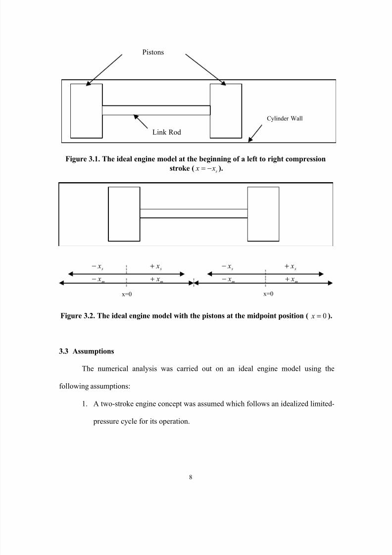
3.2. The ideal engine model with the pistons at the midpoint position ( 0= x ).
3.3. Pressure volume diagram of limited-pressure cycle.
3.4. Four regions can be seen for the pressure balance due to the limited-pressure
cycle of operation.
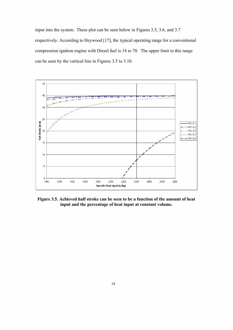
3.5. Obtained half stroke can be seen to be a function of the amount of heat input and
the percentage of heat input at constant volume.
3.6. The constant pressure expansion coordinate defines how much heat is input at
constant pressure. It can be seen to be a function of the heat input and φ.
The compression ratio is defined by the geometry of the engine and the achieved
half stroke.
The period of the operating cycle is seen to be the smallest for a Diesel cycle of
8/11/2019 A Diesel Two-Stroke Linear Engine
http://slidepdf.com/reader/full/a-diesel-two-stroke-linear-engine 7/73
3.12. Slider Velocity versus time shows the velocity is near constant for most of the
stroke.
3.13. Work output versus time shows positive work being performed during the
expansion stroke and negative work during the compression stroke. During the
gas exchange operation when the exhaust port is open, work output can be seen to
have offsetting positive and negative work regions.
3.14. In-cylinder pressure versus time.
3.15. In-cylinder pressure versus in-cylinder volume shows a pressure trace of the
idealized model.
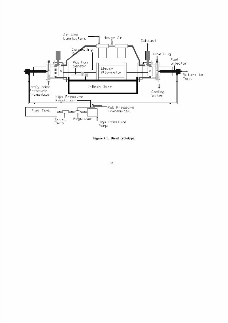
4.1. Diesel prototype.
4.2. Dimensional sketch of cylinder assembly.
4.3. Diesel prototype engine control module block diagram.
4.4. Overhead view of engine setup.
4.5. Front view of engine.

8/11/2019 A Diesel Two-Stroke Linear Engine
http://slidepdf.com/reader/full/a-diesel-two-stroke-linear-engine 8/73
Nomenclature
b bore diameter of the engine
sm mass of the piston slider
vC constant volume specific heat
pC constant pressure specific heat
n ratio of specific heatsr compression ratio
m x maximum theoretical half-stroke length of the engine
s x maximum achieved half-stroke length of the engine
epr x right exhaust port closing coordinate
epl x left exhaust port closing coordinate
a x constant pressure expansion end coordinate
x instantaneous piston position
f F friction force required to move the piston
φ percentage of total heat input performed at constant volume
inQ quantity of heat added during one stroke
f

8/11/2019 A Diesel Two-Stroke Linear Engine
http://slidepdf.com/reader/full/a-diesel-two-stroke-linear-engine 9/73
inT intake air temperature
2T air temperature at point 2 in the cycle3T air temperature at point 3 in the cycle
aT air temperature at point a in the cycle
8/11/2019 A Diesel Two-Stroke Linear Engine
http://slidepdf.com/reader/full/a-diesel-two-stroke-linear-engine 10/73
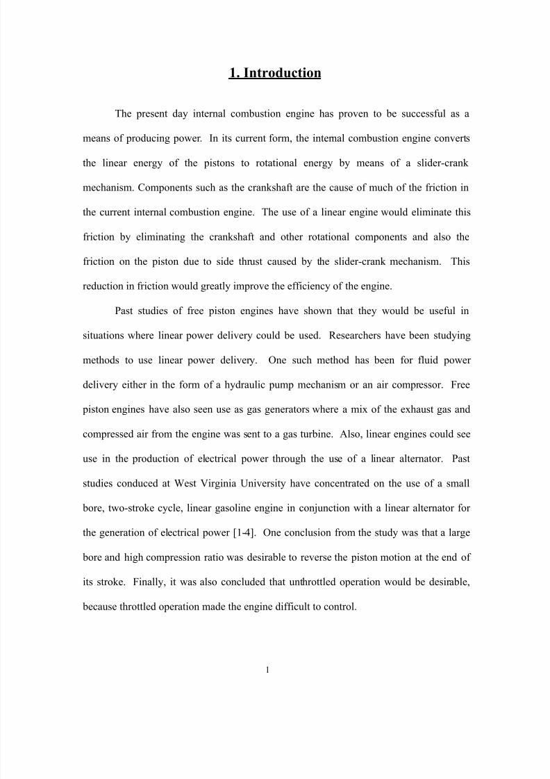
1. Introduction
The present day internal combustion engine has proven to be successful as a
means of producing power. In its current form, the internal combustion engine converts
the linear energy of the pistons to rotational energy by means of a slider-crank
mechanism. Components such as the crankshaft are the cause of much of the friction inthe current internal combustion engine. The use of a linear engine would eliminate this
friction by eliminating the crankshaft and other rotational components and also the
friction on the piston due to side thrust caused by the slider-crank mechanism. This
reduction in friction would greatly improve the efficiency of the engine.
Past studies of free piston engines have shown that they would be useful in
situations where linear power delivery could be used. Researchers have been studying
methods to use linear power delivery. One such method has been for fluid power
delivery either in the form of a hydraulic pump mechanism or an air compressor. Free
piston engines have also seen use as gas generators where a mix of the exhaust gas and
8/11/2019 A Diesel Two-Stroke Linear Engine
http://slidepdf.com/reader/full/a-diesel-two-stroke-linear-engine 11/73
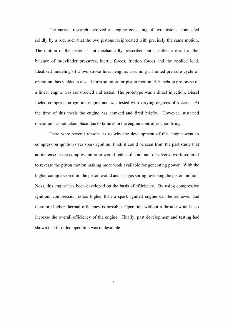
The current research involved an engine consisting of two pistons, connected
solidly by a rod, such that the two pistons reciprocated with precisely the same motion.
The motion of the piston is not mechanically prescribed but is rather a result of the
balance of in-cylinder pressures, inertia forces, friction forces and the applied load.
Idealized modeling of a two-stroke linear engine, assuming a limited pressure cycle of
operation, has yielded a closed form solution for piston motion. A benchtop prototype of
a linear engine was constructed and tested. The prototype was a direct injection, Diesel
fueled compression ignition engine and was tested with varying degrees of success. At
the time of this thesis the engine has cranked and fired briefly. However, sustained
operation has not taken place due to failures in the engine controller upon firing.
There were several reasons as to why the development of this engine went to
compression ignition over spark ignition. First, it could be seen from the past study that
an increase in the compression ratio would reduce the amount of adverse work required
to reverse the piston motion making more work available for generating power. With the
higher compression ratio the piston would act as a gas spring reversing the piston motion.
8/11/2019 A Diesel Two-Stroke Linear Engine
http://slidepdf.com/reader/full/a-diesel-two-stroke-linear-engine 12/73
2. Literature Review
Free piston engines have been investigated for many years. A study of literature
and patents pertaining to this scrutiny has been presented in this chapter.
Achten [5] studied and documented the different types of free piston engines. His
study concentrated on the conceptual differences between the different mechanisms.
Crankless gas generator piston engines were used in the 1950’s. These engines
consisted of opposed pistons that were each directly connected to an air compressor
piston. The mix of compressed air and engine exhaust was then sent to drive a gas
turbine Cleveland Diesel Engine [6]. Frey et al. [7] built and tested a free piston gas
generator turbine set that was sized for an automobile.
Galitello [8] patented a two-stroke cycle, variable compression, free piston
engine. The engine consisted of two directly opposed identical, outward compressing
pistons that were rigidly connected. Power was extracted from a central hydraulic
cylinder or by a linear alternator. The engine was spark ignited and computer controlled.
Th t t l t d th d i d t t f l b ti ti

8/11/2019 A Diesel Two-Stroke Linear Engine
http://slidepdf.com/reader/full/a-diesel-two-stroke-linear-engine 13/73
for the engine vibration. The engine also had oil cooling by means of cooling jackets
around the cylinders.
Widener and Ingram [10] submitted a numerical model of a free piston linear
generator for a hybrid vehicle modeling study. The model addressed the use of a free
piston engine coupled with a linear generator as a potential auxiliary power unit in
hybrid electric vehicles. The feasibility of such a model was analyzed with regards to
power output and efficiency of the unit with reference to conversion of mechanical power
output of the linear engine to electrical power output. The study was conducted on a two-
stroke cycle engine and a reciprocating rig developed to characterize the operation of the
generator.
In the thesis of Goldsborough [11], a numerical simulation of a two-stroke cycle
free piston engine was performed. This study concentrated on the analysis of
homogenous charge compression ignition (HCCI) of hydrogen fuel. The author
calculated the HCCI process to be near constant volume which enable the engine to
operate on a very lean fuel-air charge. The study concluded that charge temperature at

8/11/2019 A Diesel Two-Stroke Linear Engine
http://slidepdf.com/reader/full/a-diesel-two-stroke-linear-engine 14/73
components of a commercially available chainsaw engine. The testing of the engine was
performed under several loading conditions. It was found that under idle conditions the
ignition timing had to be advanced to the point that spark occurred just after port closing
to insure that the piston motion was reversed. This caused a large section of adverse
work to be performed in reversing the piston, and a high coefficient of variance (COV) in
the indicated mean effective pressure (iMEP). In a loaded highly, retarded timing case it
was found that the adverse work was eliminated and the COV (iMEP) was reduced. This
resulted in the engine operating more like a conventional internal combustion engine.
The fundamental modeling of the engine lead to a closed form solution for the piston
motion in dimensionless parameters. The numerical model of the engine then took the
fundamental model and solved it in a dimensional form. The numerical model yielded
theoretical in-cylinder pressure and displacement plots. From the different studies
conducted it was determined that the design of a linear engine should be large bore and
unthrottled, which would suggest a Diesel engine. The results of the research performed
at West Virginia University have been published in several articles. These papers include

8/11/2019 A Diesel Two-Stroke Linear Engine
http://slidepdf.com/reader/full/a-diesel-two-stroke-linear-engine 15/73
3. Fundamental Analysis
3.1 Introduction
The analysis presented below examines an ideal two-stroke engine with two
opposed pistons connected solidly by a link rod and following the air-standard limited-
pressure cycle of operation. A simple case of an idling engine or an engine from which
power is extracted with constant force was examined. The air standard limited-pressure
cycle of operation was assumed so as to provide pressures prevalent within the cylinders
during idling operation of the engine. This created a fundamental analysis, that was
useful in the study of the effects of heat input and the percent of heat input at constantvolume.
It is understood that real systems are far more complex in comparison to the ideal
case assumed in the following analysis and that a numerical analysis, similar to Atkinson
et al. [4], might have to be employed in order to better understand the complex system.
However, the fundamental analysis presented provides a basic understanding of the linear

8/11/2019 A Diesel Two-Stroke Linear Engine
http://slidepdf.com/reader/full/a-diesel-two-stroke-linear-engine 16/73
symmetric strokes and are outward compressing. The engine was assumed to have
instantaneous intake and exhaust blow down at the opening position of the ports and
partial instantaneous heat release at the outermost position with the balance of the heat
release occurring at constant pressure. Being a linear reciprocating engine, the piston
does not encounter a top dead center position or a bottom dead center position, but rather
has an innermost (for the left piston; s x x = ) and outermost position (for the left piston;
s x x −= ). The analysis was carried out in a dimensional form on this idealized engine,
based on the assumption that an idling case of operation was in progress and the only
load encountered was a frictional force. A better understanding of the model can be
gained from the schematic presented in Figure 3.1. The maximum theoretical half stroke
length of the piston is xm, while the maximum actual half stroke length of the piston is x s
as seen in Figure 3.2 . The piston on a left to right stroke traverses from – x s to + x s. A
fundamental analysis was carried out by taking into consideration the heat added during
one cycle, the intake pressures in the two cylinders, the friction force encountered by the
pistons during their motion from the outermost position to the innermost position and the
8/11/2019 A Diesel Two-Stroke Linear Engine
http://slidepdf.com/reader/full/a-diesel-two-stroke-linear-engine 17/73
Link Rod
Cylinder Wall
Pistons
Figure 3.1. The ideal engine model at the beginning of a left to right compressionstroke ( s x x −= ).
s x− s x+ s x− s x+m x− m x+ m x− m x+
x=0 x=0

8/11/2019 A Diesel Two-Stroke Linear Engine
http://slidepdf.com/reader/full/a-diesel-two-stroke-linear-engine 18/73
2. An idling case of operation with only a frictional force being encountered
during the engine operation was assumed.
3. The heat input to the engine was used entirely for the work done to overcome
the friction drag force acting on the piston (no heat loss).
The analysis was carried out on the idealized engine in a numerical form. Given
these assumptions, a numerical solution in velocity versus position, velocity versus time
and position versus time were obtained and are presented.
3.4 Dynamic Model
The model begins with a dynamic analysis of the engine. Consider the case of the
engine in a left to right movement. The force balance of the system is:
( ) ( ) 044 2
222
=−−−dt
xd m F
b x P
b x P s f r l
ππ
where P l is the left in-cylinder pressure, P r is the right in-cylinder pressure, F f is the
frictional force applied to the engine, m s is the mass of the slider, b is the bore of the
engine, t is time, and x is the slider displacement. Both cylinder pressures are a function
8/11/2019 A Diesel Two-Stroke Linear Engine
http://slidepdf.com/reader/full/a-diesel-two-stroke-linear-engine 19/73
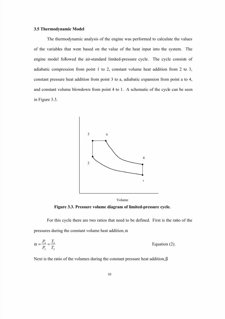
3.5 Thermodynamic Model
The thermodynamic analysis of the engine was performed to calculate the values
of the variables that were based on the value of the heat input into the system. The
engine model followed the air-standard limited-pressure cycle. The cycle consists of
adiabatic compression from point 1 to 2, constant volume heat addition from 2 to 3,
constant pressure heat addition from point 3 to a, adiabatic expansion from point a to 4,
and constant volume blowdown from point 4 to 1. A schematic of the cycle can be seen
in Figure 3.3.
2
3 a
4

8/11/2019 A Diesel Two-Stroke Linear Engine
http://slidepdf.com/reader/full/a-diesel-two-stroke-linear-engine 20/73
33 T T
V V aa ==β Equation (3).
Where T 2, T 3, and T a are the average in-cylinder temperatures at the corresponding
points. These two ratios define how much of the heat input occurs at constant volume
and how much occurs at constant pressure. The temperatures in the cylinders during the
cycle can be defined as functions of the slider displacement and the intake temperature
T in and φ the percentage of the heat input that is at constant volume:
1
2
−
−−=
n
sm
epr min x x
x xT T Equation (4).
1
3
−
−−
+=
n
sm
epr m
inv
in
x x
x x
T mC Q
T φ
Equation (5).
( ) 11
−
−−++−=
n
sm
epr min
v
in
p
ina x x
x xT
mC Q
mC Q
T φφ
Equation (6).
where x m is the maximum half stroke, x epr is the right exhaust port closing coordinate, C v
and C p are the specific heats for the working fluid, Q in is the total heat input into the
system, n is the ratio of the specific heats, and m is the mass of the air in the cylinder.

8/11/2019 A Diesel Two-Stroke Linear Engine
http://slidepdf.com/reader/full/a-diesel-two-stroke-linear-engine 21/73
φβ
1= . Equation (10).
φα
−=1
1. Equation (11).
With these definitions of α and β, stroke length, constant pressure expansion length,
frictional force, and compression ratio can be calculated. By substituting equations 4 and
5 into Equation 2, α becomes:
1
1
+
−−
=
−
inv
n
sm
epr min
T C
x x
x x
mQ
φα .
thus x s is solved for:
−−=−1
1
nin
epr mm s
Q
x x x x
φ
. Equation (12).

8/11/2019 A Diesel Two-Stroke Linear Engine
http://slidepdf.com/reader/full/a-diesel-two-stroke-linear-engine 22/73
s f f x F W 2= ,
invoking limited pressure cycle efficiency:
( ) ( ) −+−−−= − 11
111 1 αβα
αβηnr
n
nth
( )( )
( )
( ) −+−−
−−−=
−
111
11
αβααβ
ηn x x
x x nn
epr m
smth
( )( )
( )
( ) −+−−
−−
−=
−
111
12
1
αβααβ
n x x x x
mQ
x F n
n
epr m
smin s f .
The frictional force then becomes
( )( )
( )
( )
s
nn
epr m
smin
f xm
n x x x x
Q
F 2
111
1
1
−+−
−
−−−
=
−
αβααβ
. Equation (15).
3.6 Pressure Balance
During a left to right stroke of the slider the cylinder pressures will be governed
by several equations because of the constant pressure heat addition, the placement of the
port openings and closings, and the scavenging process. Based on the prototype engine,

8/11/2019 A Diesel Two-Stroke Linear Engine
http://slidepdf.com/reader/full/a-diesel-two-stroke-linear-engine 23/73
is open the pressure remains constant. The governing equations for the cylinder pressures
and pressure force F p are listed in Table 3.1.
Displacement
xa xeprr x=0 xepl-xs +x s
A B C D
Expansion Strokein Left Cylinder
Compression Stroke inRight Cylinder
Figure 3.4. Four regions can be seen for the pressure balance due to the limited-pressure cycle of operation.

8/11/2019 A Diesel Two-Stroke Linear Engine
http://slidepdf.com/reader/full/a-diesel-two-stroke-linear-engine 24/73
15
Table 3.1. In-cylinder pressures and pressure force as a function of the slider displacement.
Component A B C D
P l(x) P o ( )( )nm
namo
x x x x P
++ ( )
( )nm
namo
x x x x P
++ P in
P r (x) P in P in( )
( )nm
nepr min
x x
x x P
−− ( )
( )nm
nepr min
x x
x x P
−−
F p(x) ( )4
2b P P ino
π− ( )
( ) 4
2b P
x x
x x P inn
m
namo π
−
++ ( )
( )( )( ) 4
2b
x x
x x P
x x
x x P n
m
nepr min
nm
namo π
+−
−++ ( )
( ) 4
2b
x x
x x P P
nm
nepr min
inπ
−−−

8/11/2019 A Diesel Two-Stroke Linear Engine
http://slidepdf.com/reader/full/a-diesel-two-stroke-linear-engine 25/73
From analysis of Figure 3.4, it can be seen that regime A corresponds to the point
when x ≥ -x s and x < x a, regime B corresponds to the point when x ≥ xa and x < x epr ,
regime C corresponds to the point when x ≥ xepr , and x < x epl , and regime D corresponds
to the point when x ≥ xepl and x ≤ xs. P 0 is the pressure in the cylinder caused by the
constant volume heat addition. P 0 is related to the pressure before the constant volume
heat addition and α by:
20 P P α=
where P 2 is the pressure in the cylinder after the adiabatic compression (P r at x=x s), this
pressure can be found with knowledge of the intake pressure P in by
( )( )n sm
nepr m
in x x
x x P P
−−=2 . Equation (16).
3.7 Numerical Integration
Once all of the above relationships were derived a computer program to solve
Equation 1 for the acceleration was developed. This program first solved the
thermodynamic model for the half stroke x s, the constant pressure expansion end
8/11/2019 A Diesel Two-Stroke Linear Engine
http://slidepdf.com/reader/full/a-diesel-two-stroke-linear-engine 26/73
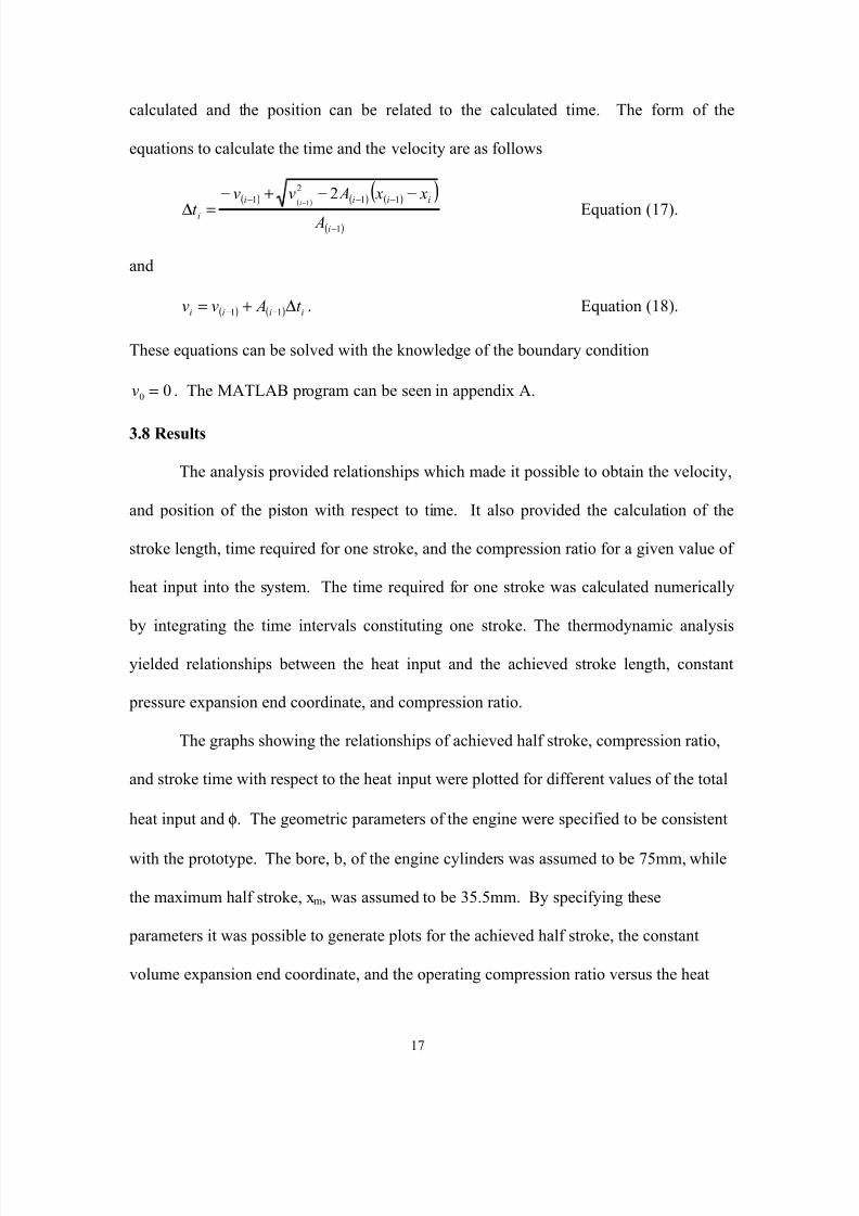
calculated and the position can be related to the calculated time. The form of the
equations to calculate the time and the velocity are as follows
( ) ( ) ( ) ( )( )( )1
112
1 21
−
−−− −−+−=∆ −
i
iiii
i A
x x Avvt
iEquation (17).
and
( ) ( ) iiii t Avv ∆+= −− 11 . Equation (18).
These equations can be solved with the knowledge of the boundary condition
00 =v . The MATLAB program can be seen in appendix A.
3.8 Results
The analysis provided relationships which made it possible to obtain the velocity,
and position of the piston with respect to time. It also provided the calculation of the
stroke length, time required for one stroke, and the compression ratio for a given value of
heat input into the system. The time required for one stroke was calculated numerically
by integrating the time intervals constituting one stroke. The thermodynamic analysis
ld d l h b h h d h h d k l h
8/11/2019 A Diesel Two-Stroke Linear Engine
http://slidepdf.com/reader/full/a-diesel-two-stroke-linear-engine 27/73
input into the system. These plot can be seen below in Figures 3.5, 3.6, and 3.7
respectively. According to Heywood [17], the typical operating range for a conventional
compression ignition engine with Diesel fuel is 18 to 70. The upper limit to this range
can be seen by the vertical line in Figures 3.5 to 3.10.

8/11/2019 A Diesel Two-Stroke Linear Engine
http://slidepdf.com/reader/full/a-diesel-two-stroke-linear-engine 28/73
Figure 3.6. The constant pressure expansion coordinate defines how much heat isinput at constant pressure. It can be seen to be a function of the heat input and φφ.

8/11/2019 A Diesel Two-Stroke Linear Engine
http://slidepdf.com/reader/full/a-diesel-two-stroke-linear-engine 29/73
Figure 3.7. The compression ratio is defined by the geometry of the engine and theachieved half stroke.
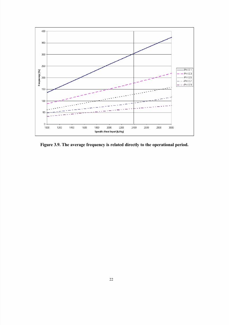
From the numerical integration the stroke time, average frequency, and mid-
stroke slider velocity can be shown relative to the specific heat input and the value of φ.

8/11/2019 A Diesel Two-Stroke Linear Engine
http://slidepdf.com/reader/full/a-diesel-two-stroke-linear-engine 30/73
Figure 3.8. The period of the operating cycle is seen to be the smallest for a Dieselcycle of operation. The cycle period increases as the amount of heat input at
constant volume increases.
8/11/2019 A Diesel Two-Stroke Linear Engine
http://slidepdf.com/reader/full/a-diesel-two-stroke-linear-engine 31/73
Figure 3.9. The average frequency is related directly to the operational period.
8/11/2019 A Diesel Two-Stroke Linear Engine
http://slidepdf.com/reader/full/a-diesel-two-stroke-linear-engine 32/73
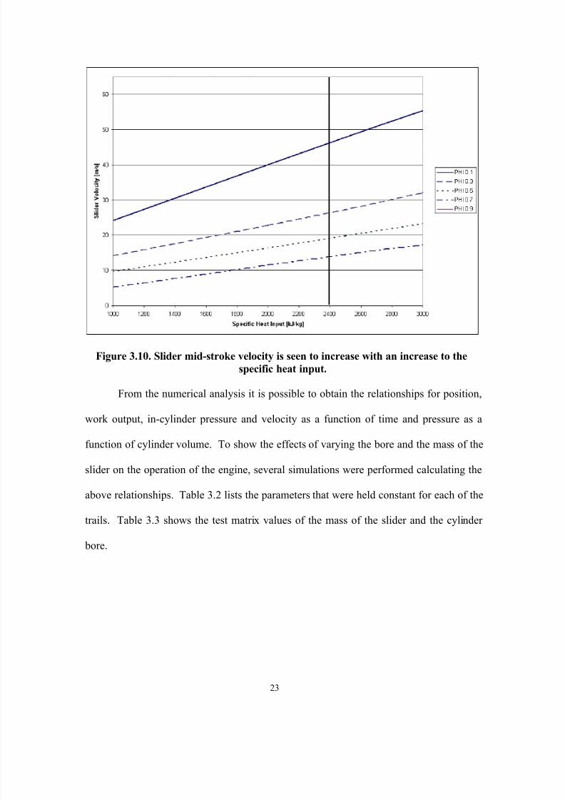
Figure 3.10. Slider mid-stroke velocity is seen to increase with an increase to thespecific heat input.
From the numerical analysis it is possible to obtain the relationships for position,
work output, in-cylinder pressure and velocity as a function of time and pressure as a
8/11/2019 A Diesel Two-Stroke Linear Engine
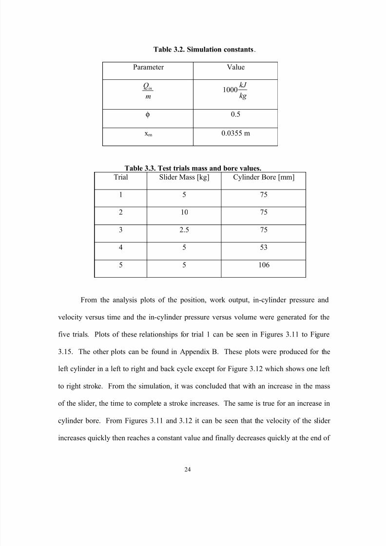
http://slidepdf.com/reader/full/a-diesel-two-stroke-linear-engine 33/73
Table 3.2. Simulation constants .
Parameter Value
mQ in 1000
kg kJ
φ 0.5
xm 0.0355 m
Table 3.3. Test trials mass and bore values.Trial Slider Mass [kg] Cylinder Bore [mm]
1 5 75
2 10 75
3 2.5 75
4 5 53
5 5 106
8/11/2019 A Diesel Two-Stroke Linear Engine
http://slidepdf.com/reader/full/a-diesel-two-stroke-linear-engine 34/73
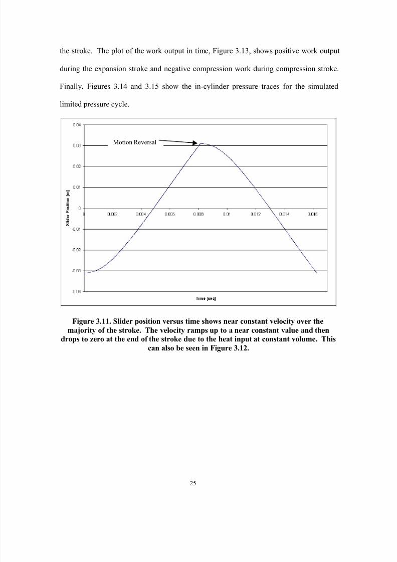
the stroke. The plot of the work output in time, Figure 3.13, shows positive work output
during the expansion stroke and negative compression work during compression stroke.
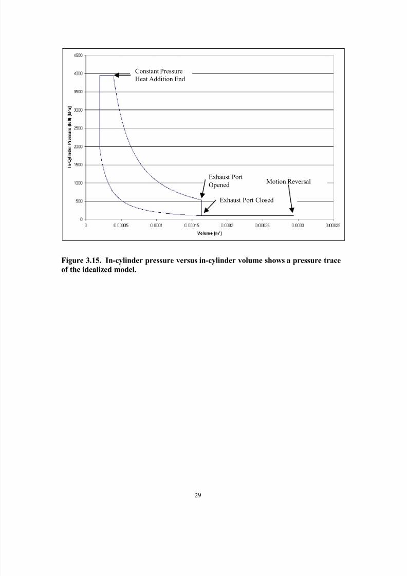
Finally, Figures 3.14 and 3.15 show the in-cylinder pressure traces for the simulated
limited pressure cycle.
Motion Reversal

8/11/2019 A Diesel Two-Stroke Linear Engine
http://slidepdf.com/reader/full/a-diesel-two-stroke-linear-engine 35/73
Figure 3.12. Slider Velocity versus time shows the velocity is near constant for mostof the stroke.
Motion Reversal
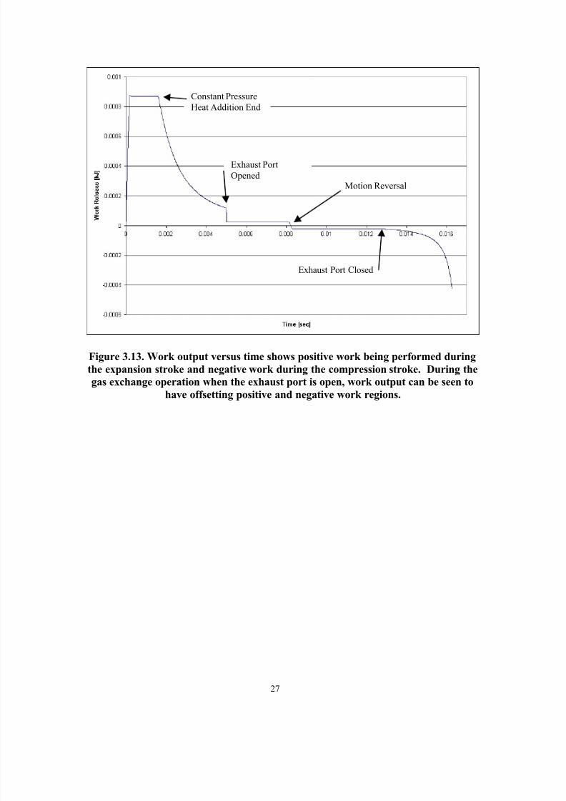
8/11/2019 A Diesel Two-Stroke Linear Engine
http://slidepdf.com/reader/full/a-diesel-two-stroke-linear-engine 36/73
Figure 3.13. Work output versus time shows positive work being performed duringthe expansion stroke and negative work during the compression stroke. During thegas exchange operation when the exhaust port is open, work output can be seen to
have offsetting positive and negative work regions.
Constant PressureHeat Addition End
Exhaust PortOpened
Motion Reversal
Exhaust Port Closed

8/11/2019 A Diesel Two-Stroke Linear Engine
http://slidepdf.com/reader/full/a-diesel-two-stroke-linear-engine 37/73
Figure 3.14. In-cylinder pressure versus time
Constant PressureHeat Addition End
Exhaust PortOpened
Exhaust Port Closed
8/11/2019 A Diesel Two-Stroke Linear Engine
http://slidepdf.com/reader/full/a-diesel-two-stroke-linear-engine 38/73
Figure 3.15. In-cylinder pressure versus in-cylinder volume shows a pressure traceof the idealized model.
Exhaust PortOpened
Exhaust Port Closed
Motion Reversal
Constant PressureHeat Addition End
8/11/2019 A Diesel Two-Stroke Linear Engine
http://slidepdf.com/reader/full/a-diesel-two-stroke-linear-engine 39/73
4. Engine Prototype
4.1 Description
The Diesel prototype of 75 mm bore and 71 mm stroke was sized to use two-
stroke cycle personal watercraft (Kawasaki Jetski 300sx) components to reduce
development time and cost. Cylinder heads were designed and fabricated that allowed
for direct fuel injection and also provided water cooling to the Kawasaki cylinders. The
pistons also were from the Kawasaki engine but were machined to remove the lower
portion of the piston skirt. This was done to prevent the skirt from contacting the bottom
end that was designed to allow the engine to be scavenged by in house compressed air.
The pistons were directly connected by an aluminum rod that had provisions for
mounting the moving portion of the position sensor and the translator magnets for the
linear alternator. A simple I-beam frame provided support for the cylinders, alternator,
and the stationary portion of the position sensor.
A single manually operated valve regulated air pressure to the engine.
L b i ti t th gi li d th gh th i t k i b f i li i t l

8/11/2019 A Diesel Two-Stroke Linear Engine
http://slidepdf.com/reader/full/a-diesel-two-stroke-linear-engine 40/73
Another variable dependent on the stroke was the compression ratio, which had a
theoretical maximum, for this particular engine of approximately 50:1. This wascalculated with the knowledge of exhaust port locations, the dimensions of the cylinder,
clearance volume and assuming that the motion is reversed exactly at the point of contact
when the piston meets the head. The clearance volume was assumed to be the volume in
the head, which allows access to the cylinder for the glow plugs and fuel injectors. A
sketch of the major engine components is shown in Figure 4.1.
Fuel delivery was preformed by a common rail, direct injection system. The fuel
injectors (Bosch part # B 445 110 130) were supplied by a high-pressure pump (Bosch
part # B445 010 035-01) that maintained the common rail at a pressure controlled by the
ECM, usually set to 9,000 psi. The high-pressure pump maintained the pressure through
the use of a pulse width modulated regulator. Supplying the high-pressure pump was a
automotive fuel pump (Master part # E2000) that was regulated at 38 psi. Fuel metering
was pulse width modulated by the ECM and was manually adjusted by means of a
potentiometer for each cylinder. The ECM allowed for the adjustment of the pulse width
8/11/2019 A Diesel Two-Stroke Linear Engine
http://slidepdf.com/reader/full/a-diesel-two-stroke-linear-engine 41/73
32
Figure 4.1. Diesel prototype.

8/11/2019 A Diesel Two-Stroke Linear Engine
http://slidepdf.com/reader/full/a-diesel-two-stroke-linear-engine 42/73
Figure 4.2. Dimensional sketch of cylinder assembly (dimension in mm).
A listing of the parts and description of their geometry and function is given in
Table 4.1 below.
Table 4.1. Prototype Component Description.
Component DescriptionCylinders Kawasaki Jetski 300sx with 75 mm bore
8/11/2019 A Diesel Two-Stroke Linear Engine
http://slidepdf.com/reader/full/a-diesel-two-stroke-linear-engine 43/73
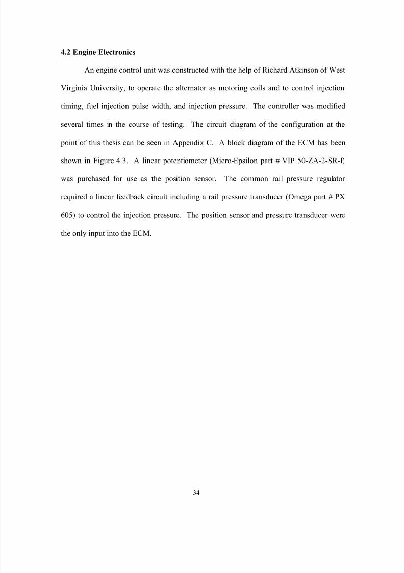
4.2 Engine Electronics
An engine control unit was constructed with the help of Richard Atkinson of WestVirginia University, to operate the alternator as motoring coils and to control injection
timing, fuel injection pulse width, and injection pressure. The controller was modified
several times in the course of testing. The circuit diagram of the configuration at the
point of this thesis can be seen in Appendix C. A block diagram of the ECM has been
shown in Figure 4.3. A linear potentiometer (Micro-Epsilon part # VIP 50-ZA-2-SR-I)
was purchased for use as the position sensor. The common rail pressure regulator
required a linear feedback circuit including a rail pressure transducer (Omega part # PX
605) to control the injection pressure. The position sensor and pressure transducer were
the only input into the ECM.
8/11/2019 A Diesel Two-Stroke Linear Engine
http://slidepdf.com/reader/full/a-diesel-two-stroke-linear-engine 44/73
35
Figure 4.3. Diesel prototype engine control module block diagram.

8/11/2019 A Diesel Two-Stroke Linear Engine
http://slidepdf.com/reader/full/a-diesel-two-stroke-linear-engine 45/73
In order to directly observe the nature of combustion in this novel engine,
piezoelectric in-cylinder pressure transducers [PCB Part #508 and Part #547] were
mounted with direct access to the combustion chamber.
4.3 Prototype Test Platform
The experimental engine was designed and developed in-house with the
assistance of Thomas McDaniel, along with the engine controller with the assistance of
Richard Atkinson. The engine was tested with several updates to the ECU with varying
degrees of success. Figure 4.4 shows an overhead view of the engine setup. Figure 4.5
shows another view of the engine prototype and the dedicated bench of steel plates
weighing approximately 600 lbs., constructed to reduce the severity of vibrations during
early testing. The experimental results and conclusions have been presented in the next
chapter.
Fuel Pump
Engine ControlUnit

8/11/2019 A Diesel Two-Stroke Linear Engine
http://slidepdf.com/reader/full/a-diesel-two-stroke-linear-engine 46/73
In the top left corner of Figure 4.4 the high pressure fuel pump can be seen. In the top
right corner is the ECM. The top middle the intake and lubrication system can be seen.
Along the bottom of Figure 4.4 is the test engine.
Figure 4.5. Front view of the engine.

8/11/2019 A Diesel Two-Stroke Linear Engine
http://slidepdf.com/reader/full/a-diesel-two-stroke-linear-engine 47/73
8/11/2019 A Diesel Two-Stroke Linear Engine
http://slidepdf.com/reader/full/a-diesel-two-stroke-linear-engine 48/73
8/11/2019 A Diesel Two-Stroke Linear Engine
http://slidepdf.com/reader/full/a-diesel-two-stroke-linear-engine 49/73
6. Conclusions and Recommendations
6.1. Conclusions
The Diesel linear engine offers the potential to generate and deliver power with
out the need to convert linear piston motion to rotary crankshaft motion. An idealized
model of a linear engine, consisting of two pistons linked by a solid rod has revealed the
relationship between stroke, compression ratio, heat input, operational frequency and
other parameters. The model shows an increase in the achieved stroke length with an
increase in the amount of heat input. The idealized model deals with over-fueling by
increasing the stroke of the engine to the maximum. It is believed that this is not how the
engine would behave in reality. It is obvious that in the case of over-fueling, incomplete
combustion would occur. Also the effects of varying the bore and the sliding mass on
operating frequency, and power output have been shown for a given heat input. An
increase in cylinder bore or slider mass effect the system by increasing the amount of
time for a stoke.
Th t t h d f l h t i ti i th t ti g f d Th

8/11/2019 A Diesel Two-Stroke Linear Engine
http://slidepdf.com/reader/full/a-diesel-two-stroke-linear-engine 50/73
This could be accomplished in several ways. A method of protecting the cranking driver
transistors from the current generated by the engine firing could be developed. Another
possible solution would be to implement the type of system first utilized on the gasoline
prototype develop at West Virginia University. This system used two automotive starter
pull back solenoids acting on a steel connecting rod to crank the system. This would
allow the cranking circuitry to be separate from the power generation circuitry,
preventing the current problem. This is a less appealing alternative than the previously
mentioned because it involves a redesign of both the ECU and the engine itself to provide
the cranking circuitry, a steel connecting rod and the space needed to locate the solenoids.
Once the cranking problem is solved it is believed that the engine will run and in-cylinder
data can be collected.

8/11/2019 A Diesel Two-Stroke Linear Engine
http://slidepdf.com/reader/full/a-diesel-two-stroke-linear-engine 51/73
REFERENCES
[1] Clark, N., Nandkumar, S., Famouri, P., “Fundamental Analysis of a Linear Two-
Cylinder Internal Combustion Engine,” SAE 982692, 1999.
[2] Clark, N., McDaniel, T., Atkinson, R., Nandkumar, S., Atkinson, C., Petreanu, S.,
Tennant C., Famouri, P., Modeling and Development of a Linear Engine,” ICE-Vol.
30-2 Proceeding of the Spring Technical Conference of the ASME Internal
Combustion Engine Division, Book No. G1074B, 1998.
[3] Clark, N., Nandkumar, S., Atkinson, C., Atkinson, R., McDaniel, T., Petreanu, S.,
Famouri, P., “Operation of a Small Bore Two-Stroke Linear Engine,” ASME 98-
ICE-120, 1998.
[4] Atkinson, C., Petreanu, S., Clark, N., Atkinson, R., McDaniel, T., Nandkumar, S.,
Famouri, P., “Numerical Simulation of a Two-Stroke Linear Engine-Alternator
Combination,” SAE 1999-01-0921, 1999.
[5] Achten, A. J., “A Review of Free Piston Engine Concepts,” International Off-
Highway & Powerplant Congress & Exposition, SAE 941776, 1994.
[6] Cleveland Diesel Engine Division, 1957, “History and Description of the Free
Piston Engine- Gas Turbine Power,” (authors unknown to GM).[7] Frey, D. N., Klotsch, P., Egli, A., “The Automotive Free-Piston-Turbine Engine,”

8/11/2019 A Diesel Two-Stroke Linear Engine
http://slidepdf.com/reader/full/a-diesel-two-stroke-linear-engine 52/73
[11] Goldsborough, S., “A Numerical Investigation of a Two-Stroke Cycle, Hydrogen-
Fueled, Free Piston Internal Combustion Engine,” Thesis, Colorado State
University, 1998
[12] Allais, E., “Free-Piston Engine with Operatively Independent Cam,” U.S. Patent
Application No. 416,959, Application filed September 9, 1982; U.S. Patent No.
4,480,599, Patent issued November 6, 1984.
[13] Deng, Y. A., Deng, K., “Free-Piston Engine without Compressor,” U.S. Patent
Application No. 154,145 (RDG Inventions Corporation), Application filed February
9, 1988; U.S. Patent No. 4,924,956 (RDG Inventions Corporation), Patent Issued
May 15, 1990.
[14] Heintz, R. P., “Free-Piston Engine Pump,” U.S. Patent Application No. 150,390,
Application filed May 16, 1980; U.S. Patent No. 4,369,021, Patent Issued January
18, 1983.[15] Iliev, M. D., Kervanbashiev, S. S., Karamanski, S. D., Makedonski, F. M., “Method
and Apparatus for Producing Electrical Energy from a Cyclic Combustion Process
Utilizing Coupled Pistons which Reciprocate in Unison,” U.S. Patent Application
No. 431,119 (CUV “Progress”), Application filed September 30, 1982; U.S. Patent
No. 4,532,431 (CUV “Progress”), Patent Issued July 30, 1985.[16] Rittmaster, P. A., Booth J. L., “Hydraulic Engine,” U.S. Patent Application No.
110 771 Application filed January 9 1980; U S Patent No 4 326 380 Patent
8/11/2019 A Diesel Two-Stroke Linear Engine
http://slidepdf.com/reader/full/a-diesel-two-stroke-linear-engine 53/73
APPENDIX A
Numerical Analysis Program
8/11/2019 A Diesel Two-Stroke Linear Engine
http://slidepdf.com/reader/full/a-diesel-two-stroke-linear-engine 54/73
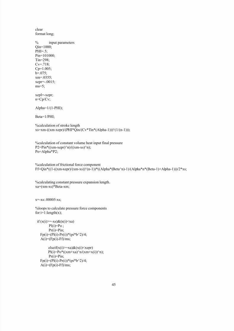
clear format long;
% input parametersQin=1000;PHI=.5;Pin=101000;Tin=298;Cv=.718;Cp=1.005;
b=.075;xm=.0355;xepr=-.0015;ms=5;
xepl=-xepr;n=Cp/Cv;
Alpha=1/(1-PHI);
Beta=1/PHI;
%calculation of stroke lengthxs=xm-((xm-xepr)/(PHI*Qin/(Cv*Tin*(Alpha-1)))̂ (1/(n-1)));
%calculation of constant volume heat input final pressureP2=Pin*((xm-xepr)^n)/((xm-xs)^n);Po=Alpha*P2;
%calculation of frictional force componentFf=Qin*((1-((xm-xepr)/(xm-xs))̂ (n-1))*((Alpha*(Beta^n)-1)/(Alpha*n*(Beta-1)+Alpha-1)))/2*xs;

8/11/2019 A Diesel Two-Stroke Linear Engine
http://slidepdf.com/reader/full/a-diesel-two-stroke-linear-engine 55/73
elseif (x(i)>=xepr)&(x(i)<xepl) Pl(i)=Po*((xm+xa)^n)/((xm+x(i))^n); Pr(i)=Pin*((xm-xepr)^n)/((xm-x(i))^n);
Fp(i)=(Pl(i)-Pr(i))*(pi*b^2)/4; A(i)=(Fp(i)-Ff)/ms;
else Pl(i)=Pin; Pr(i)=Pin*((xm-xepr)^n)/((xm-x(i))^n); Fp(i)=(Pl(i)-Pr(i))*(pi*b^2)/4; A(i)=(Fp(i)-Ff)/ms;
endend
%initializing time and velocitydt(1)=0;t(1)=0;v(1)=0;v(length(x)+1)=0;
%loop for numerical integrationfor i=2:length(x);
dt(i)=(-v(i-1)+(((v(i-1))^2)-2*A(i-1)*(x(i-1)-x(i)))^.5)/A(i-1); v(i)=v(i-1)+A(i-1)*dt(i); t(i)=t(i-1)+dt(i);
Dtime(i,1)=dt(i); Vel(i,1)=v(i); time(i,1)=t(i); end

8/11/2019 A Diesel Two-Stroke Linear Engine
http://slidepdf.com/reader/full/a-diesel-two-stroke-linear-engine 56/73
APPENDIX B
Numerical Analysis

8/11/2019 A Diesel Two-Stroke Linear Engine
http://slidepdf.com/reader/full/a-diesel-two-stroke-linear-engine 57/73
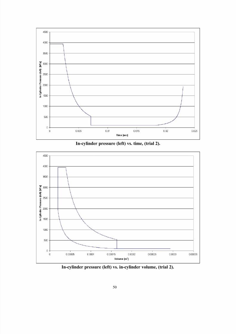
Trial 2 Output:
Slider Mass [kg] Cylinder Bore [mm]
10 75
Slider position vs time (trial 2)

8/11/2019 A Diesel Two-Stroke Linear Engine
http://slidepdf.com/reader/full/a-diesel-two-stroke-linear-engine 58/73
Slider velocity vs. time, (trial 2).
8/11/2019 A Diesel Two-Stroke Linear Engine
http://slidepdf.com/reader/full/a-diesel-two-stroke-linear-engine 59/73
In-cylinder pressure (left) vs. time, (trial 2).

8/11/2019 A Diesel Two-Stroke Linear Engine
http://slidepdf.com/reader/full/a-diesel-two-stroke-linear-engine 60/73
Trial 3 Output:
Slider Mass [kg] Cylinder Bore [mm]
2.5 75
Slider position vs time (trial 3)

8/11/2019 A Diesel Two-Stroke Linear Engine
http://slidepdf.com/reader/full/a-diesel-two-stroke-linear-engine 61/73
Slider velocity vs. time, (trial 3).

8/11/2019 A Diesel Two-Stroke Linear Engine
http://slidepdf.com/reader/full/a-diesel-two-stroke-linear-engine 62/73
In-cylinder pressure (left) vs. time, (trial 3).

8/11/2019 A Diesel Two-Stroke Linear Engine
http://slidepdf.com/reader/full/a-diesel-two-stroke-linear-engine 63/73
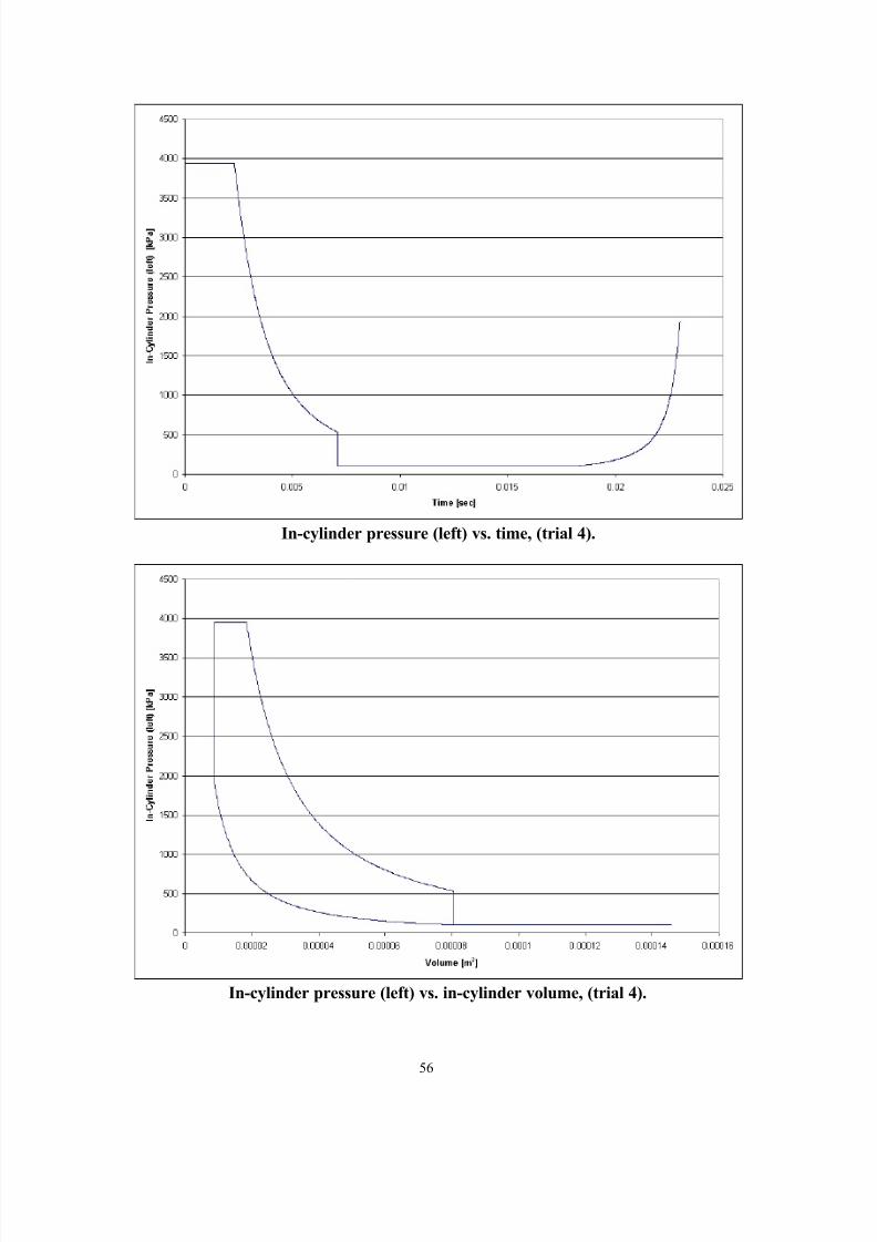
Trial 4 Output:
Slider Mass [kg] Cylinder Bore [mm]
5 53
Slider position vs time (trial 4)

8/11/2019 A Diesel Two-Stroke Linear Engine
http://slidepdf.com/reader/full/a-diesel-two-stroke-linear-engine 64/73
Slider velocity vs. time, (trial 4).
8/11/2019 A Diesel Two-Stroke Linear Engine
http://slidepdf.com/reader/full/a-diesel-two-stroke-linear-engine 65/73
In-cylinder pressure (left) vs. time, (trial 4).

8/11/2019 A Diesel Two-Stroke Linear Engine
http://slidepdf.com/reader/full/a-diesel-two-stroke-linear-engine 66/73
8/11/2019 A Diesel Two-Stroke Linear Engine
http://slidepdf.com/reader/full/a-diesel-two-stroke-linear-engine 67/73
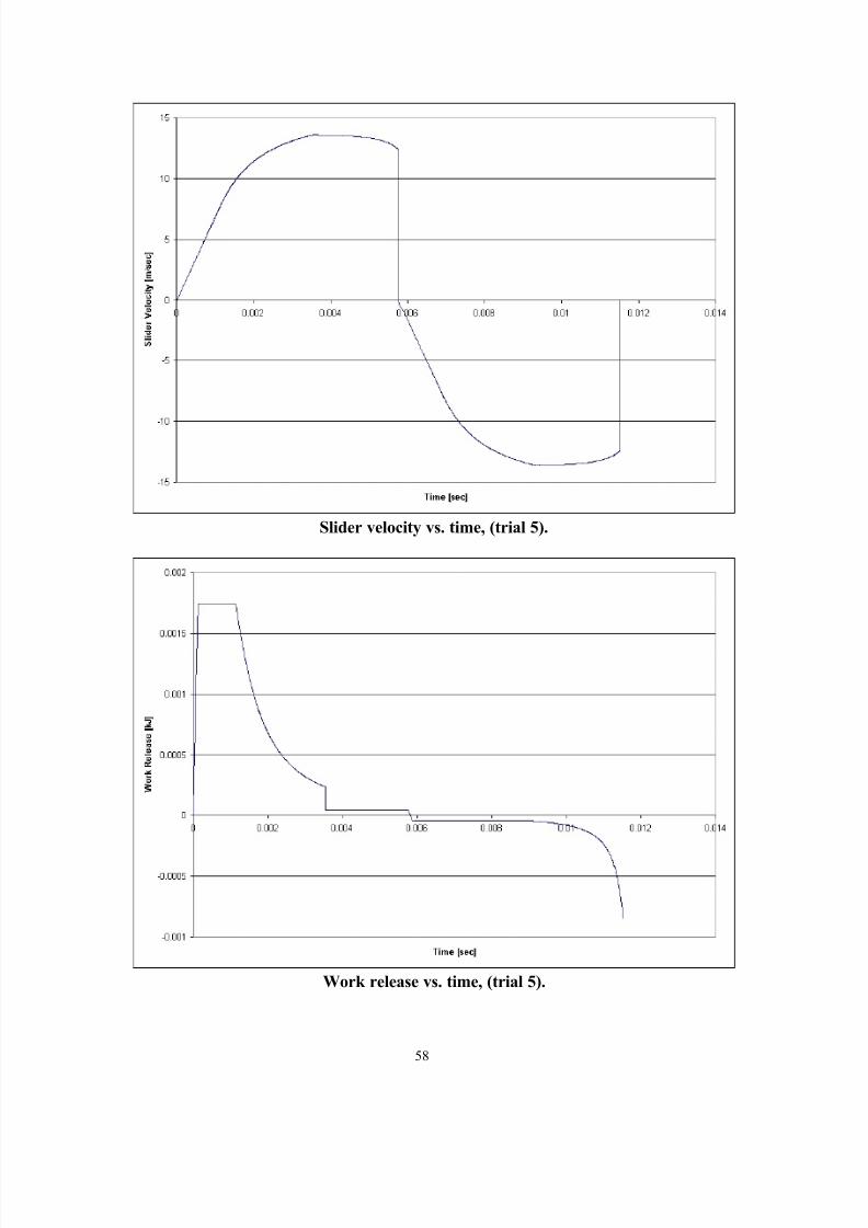
Slider velocity vs. time, (trial 5).
8/11/2019 A Diesel Two-Stroke Linear Engine
http://slidepdf.com/reader/full/a-diesel-two-stroke-linear-engine 68/73
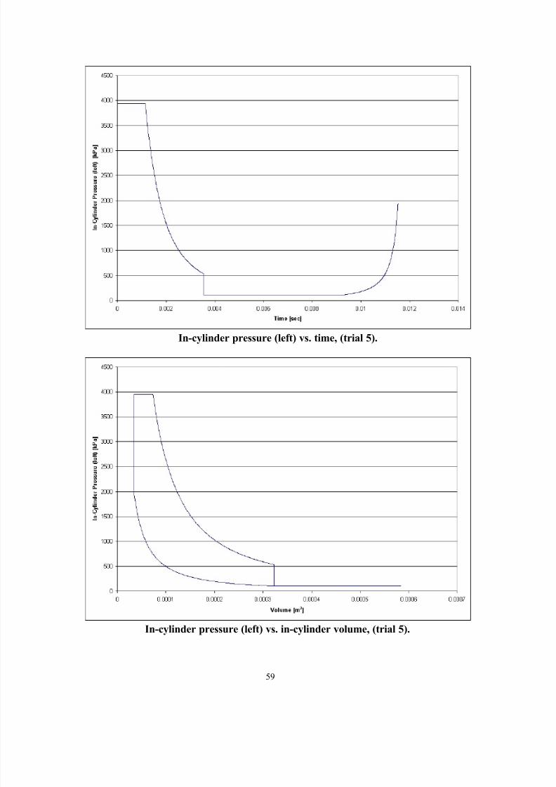
In-cylinder pressure (left) vs. time, (trial 5).

8/11/2019 A Diesel Two-Stroke Linear Engine
http://slidepdf.com/reader/full/a-diesel-two-stroke-linear-engine 69/73
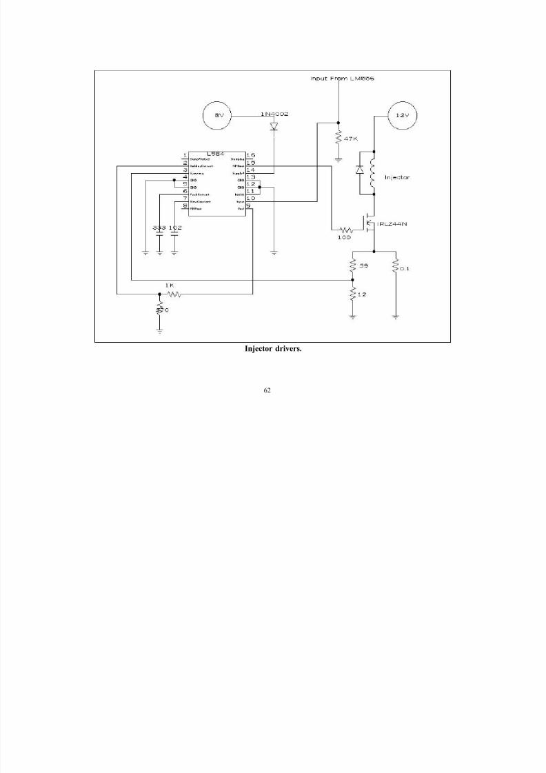
APPENDIX C
Engine Control Unit Circuit Diagrams

8/11/2019 A Diesel Two-Stroke Linear Engine
http://slidepdf.com/reader/full/a-diesel-two-stroke-linear-engine 70/73
61
Engine controller
8/11/2019 A Diesel Two-Stroke Linear Engine
http://slidepdf.com/reader/full/a-diesel-two-stroke-linear-engine 71/73
62
Injector drivers.

8/11/2019 A Diesel Two-Stroke Linear Engine
http://slidepdf.com/reader/full/a-diesel-two-stroke-linear-engine 72/73
63
Cranking circuit.
8/11/2019 A Diesel Two-Stroke Linear Engine
http://slidepdf.com/reader/full/a-diesel-two-stroke-linear-engine 73/73
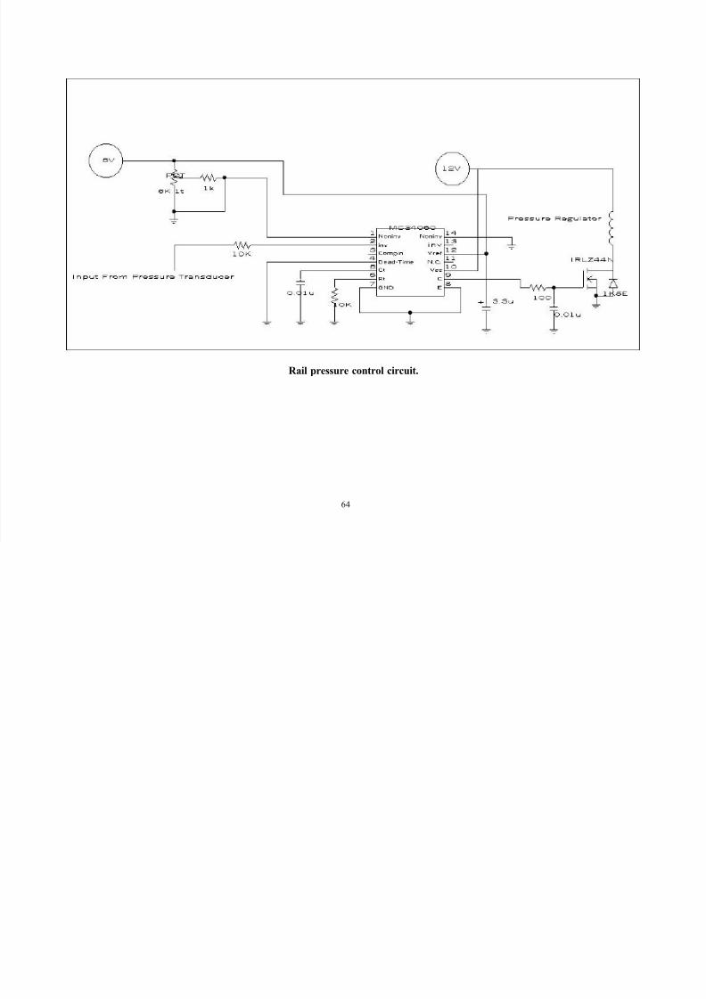
Rail pressure control circuit.