Embed Size (px)
Citation preview

Arnold Schwarzenegger Governor
A DESIGN GUIDE FOR EARLY-MARKET ELECTROCHROMIC WINDOWS
PIER
FIN
AL
PRO
JEC
T R
EPO
RT
Prepared For: California Energy Commission Public Interest Energy Research Program
Prepared By: Lawrence Berkeley National Laboratory
May 2006 CEC-500-2006-052-AT16
Prepared By: Lawrence Berkeley National Laboratory Eleanor Lee
Berkeley, California Contract No. 500-01-023 Prepared For: California Energy Commission Public Interest Energy Research (PIER) Program
Chris Scruton Contract Manager Ann Peterson Building End-Use Efficiency Team Leader Nancy Jenkins PIER Energy Efficiency Research Office Manager Martha Krebs, Ph.D. Deputy Director ENERGY RESEARCH AND DEVELOPMENT
DIVISION B. B. Blevins Executive Director
DISCLAIMER This report was prepared as the result of work sponsored by the
California Energy Commission. It does not necessarily represent the views of the Energy Commission, its employees or the State of California. The Energy Commission, the State of California, its employees, contractors and subcontractors make no warrant, express or implied, and assume no legal liability for the information in this report; nor does any party represent that the uses of this information will not infringe upon privately owned rights. This report has not been approved or disapproved by the California Energy Commission nor has the California Energy Commission passed upon the accuracy or adequacy of the information in this report.
Acknowledgments
This work was supported by the California Energy Commission through its Public Interest Energy Research (PIER) Program on behalf of the citizens of California and by the Assistant Secretary for Energy Efficiency and Renewable Energy, Office of Building Technology, State and Community Programs, Office of Building Research and Standards of the U.S. Department of Energy under Contract No. DE-AC02-05CH11231.
We are indebted to Chris Scruton and Nancy Jenkins of the California Energy Commission and Marc LaFrance of the US Department of Energy for their invaluable guidance, enthusiasm, and support throughout this multiyear project. We would also like to thank the following members of our Project Advisory Committee for taking the time to provide insightful technical and market-related input into the direction of this R&D:
Carl Wagus American Architectural Manufacturers Association Thomas Guarr Gentex Corporation Jan Berman Mechoshade Systems, Inc. Grant Brohard Pacific Gas & Electric Company Charles Hayes SAGE Electrochromics, Inc. Micheal Myser SAGE Electrochromics, Inc. John Durschinger Skidmore, Owings & Merrill LLP Gregg Ander Southern California Edison Hula Demiryont Sytecorp Kevin Settlemyre The Green Roundtable, Inc. Glenn Hughes The New York Times David Thurm The New York Times Mark Levi US General Services Administration Thomas Mifflin Wausau Window and Wall Systems
Thomas Mifflin of Wausau Window and Wall Systems provided enthusiastic and dedicated guidance, engineering support, and materials for our electrochromic field test facility’s curtainwall system without which this project probably would not have gotten off the ground. SAGE Electrochromics, Inc. also remained dedicated throughout the duration of this project, providing technical assistance and product revisions to meet our demanding project requirements.
The project team consisted of staff from a variety of disciplines within the Environmental Energy Technologies Division at the Lawrence Berkeley National Laboratory:
Andre Anders, Ph.D., Material Scientist, Thin Film Coatings Zachery Apte, IR Laboratory Tests Robert Clear, Ph.D., Human Factors, Statistical Analysis Dennis DiBartolomeo, Systems Engineering, Field Test Operations Luis Fernandes, Ph.D., Radiance Mathematica Optimizations Daniel Fuller, Testbed Networking and Communications Howdy Goudey, IR Laboratory Tests, Curtainwall Engineering, Sensors and Instrumentation Chuck Hambelton, Curtainwall Engineering, Sensors and Instrumentation Philip Haves, Ph.D., Commercial Building Systems, HVAC Interactions Vorapat Inkarojrit, Ph.D., Human Factors, High-Dynamic-Range Digital Imaging Joseph Klems, Ph.D., Heat Flow Monitoring and Thermal Analysis

Christian Kohler, Window Modeling, Testbed Networking and Communications Judy Lai, Radiance Modeling Eleanor Lee, Co-Principal Investigator Steve Marsh, Curtainwall Engineering, Sensors and Instrumentation Robin Mitchell, Window Modeling Thomas Richardson, Ph.D., Material Scientist, Electrochromics Micheal Rubin, Ph.D., Material Scientist, NFRC Francis Rubinstein, Lighting Controls, IBECS Networking and Controls Stephen Selkowitz, Principal Investigator Charles Taberski, Facilities Management, Testbed Facility Engineering and Construction Duo Wang, Data Analysis Peng Xu, Ph.D., Commercial Building Systems, HVAC Interactions Mehry Yazdanian, Heat Flow and Data Analysis And colleagues from other institutions and companies: Ren Andersen, Ph.D., National Renewable Energy Laboratory Oyvind Aschehoug, Ph.D., Visiting Professor, Norwegian University of Science and Technology, Trondheim Thibaut Falcon, École Nationale des Travaux Publics de l'État, Field Testing and Instrumentation Lixing Gu, Ph.D., Florida Solar Energy Center, Testbed Facility Engineering Aslihan Tavil, Faculty of Architecture, Istanbul Technical University, Turkey Greg Ward, Anyhere Software, Radiance Mathematica Optimizations, High-Dynamic-Range Digital Imaging Citation: Lee, E.S., S.E. Selkowitz, R.D. Clear, D.L. DiBartolomeo, J.H. Klems, L.L. Fernandes, G.J. Ward, V. Inkarojrit, M. Yazdanian. 2006. A Design Guide for Early-Market Electrochromic Windows. California Energy Commission, PIER. 500-01-023. LBNL-59950.
Preface
The Public Interest Energy Research (PIER) Program supports public interest energy research and development that will help improve the quality of life in California by bringing environmentally safe, affordable, and reliable energy services and products to the marketplace.
The PIER Program, managed by the California Energy Commission (Commission), annually awards up to $62 million to conduct the most promising public interest energy research by partnering with Research, Development, and Demonstration (RD&D) organizations, including individuals, businesses, utilities, and public or private research institutions.
PIER funding efforts are focused on the following six RD&D program areas:
• Buildings End-Use Energy Efficiency
• Industrial/Agricultural/Water End-Use Energy Efficiency
• Renewable Energy
• Environmentally-Preferred Advanced Generation
• Energy-Related Environmental Research
• Energy Systems Integration
What follows is an attachment to the final report for the Advancement of Electrochromic Windows project, Contract Number 500-01-023, conducted by the Lawrence Berkeley National Laboratory, Berkeley, CA. This project contributes to the PIER Building End-Use Energy Efficiency program.
This attachment, “Advancement of Electrochromic Windows: Journal and Technical Reports” (Attachment A-1), provides supplemental information to the project’s final report and includes journal and technical reports related to the following three subjects:
• Systems Engineering
• Performance Impacts
• Information Resources
For more information on the PIER Program, please visit the Commission's Web site at: http://www.energy.ca.gov/research/index.html or contact the Commission's Publications Unit at 916-654-5200.

Abstract Switchable variable-tint electrochromic (EC) windows preserve view out while modulating transmitted light, glare, and solar heat gains. Consumers will require objective information on the risks and benefits of this emerging technology as it enters the market in 2006. This guide provides such information and data derived from a wide variety of simulations, laboratory tests, and a 2.5-year field test of prototype large-area EC windows evaluated under outdoor sun and sky conditions. This design guide is provided to architects, engineers, building owners, and others interested in electrochromic windows. The design guide provides basic information about what is an electrochromic window, what it looks like, how fast does it switch, and what current product offerings are. The guide also provides information on performance benefits if more mature product offerings were available.
The guide is part of a set of attachments to the “Advancement of Electrochromic Windows: Journal and Technical Reports” document, produced by the Advancement of Electrochromic Windows project, funded by the California Energy Commission’s Public Interest Energy Research (PIER) Program and the U.S. Department of Energy. See the CEC PIER website for more information about this project or visit:
http://windows.lbl.gov/comm_perf/Electrochromic/electroSys-cec.htm
which duplicates the design guide material on the website and provides visitors with access to all related technical reports.

1
Table of Contents
Introduction.................................................................................................................................... 3 About the Electrochromic Window Technology ........................................................................ 5
What are electrochromic windows? ............................................................................................. 5 What types of switchable windows are there and what is their commercial status? ................... 6
Switchable windows that maintain view out ............................................................................. 6 Switchable windows that don’t maintain view .......................................................................... 7
What do electrochromic windows look like? ................................................................................ 8 Appearance when switching..................................................................................................... 9 Appearance of a multi-pane window wall............................................................................... 10
What is the switching range of electrochromic windows? ......................................................... 11 How fast do electrochromic windows switch?............................................................................ 12 Under what temperatures will electrochromic windows operate?.............................................. 13 What are the power consumption levels of EC windows?......................................................... 14 How long will EC window coatings last?.................................................................................... 14
Designing Electrochromic Windows for Buildings.................................................................. 16 What are the basic components that make up an electrochromic window?.............................. 16 What sizes and shapes do electrochromic windows come in?.................................................. 18 Are there special considerations for the framing system?......................................................... 18 What is needed to control electrochromic windows?................................................................. 20
Two-state control (fully bleached or fully colored).................................................................. 20 Intermediate-state control (fully bleached, fully colored, and levels of tint in-between)......... 22 Automated control .................................................................................................................. 22 Single- versus grouped window control ................................................................................. 23
Do EC windows need to be commissioned after installation? ................................................... 24 What are the maintenance requirements of EC windows?........................................................ 24 Are there any CSI specifications developed for EC windows?.................................................. 24 Will EC windows have NFRC labels? ........................................................................................ 24 How are dynamic windows accommodated in Title-24 and ASHRAE 90.1?............................. 25
Performance Benefits of Using Electrochromic Windows...................................................... 26 What are the benefits of using EC windows? ............................................................................ 26 What are the energy benefits of using EC windows? ................................................................ 26 What peak demand reductions can be expected from EC windows? ....................................... 28 What HVAC capacity reductions can be expected from EC windows?..................................... 30 How does EC windows increase visual comfort? ...................................................................... 30 How is view increased when EC windows are used?................................................................ 32

2
How does one compute the energy savings benefit of EC windows?....................................... 33 What is the payback of EC windows?........................................................................................ 34 What do people think of electrochromic windows?.................................................................... 35
Resources .................................................................................................................................... 40 Industry Contacts ....................................................................................................................... 40 California Utility Contacts........................................................................................................... 41 R&D Organizations .................................................................................................................... 42 Technical Reports ...................................................................................................................... 42 References................................................................................................................................. 45 Appendix: Curtainwall Details for an Electrochromic Window Wall ........................................... 46

3
Advancement of Electrochromic Windows Building Technologies Program, Environmental Energy Technologies Division
Lawrence Berkeley National Laboratory, University of California, Berkeley
Introduction
This guide provides consumer-oriented information about switchable electrochromic (EC)
windows. Electrochromic windows change tint with a small applied voltage, providing building
owners and occupants with the option to have clear or tinted windows at any time, irrespective of
whether it’s sunny or cloudy. EC windows can be manually or automatically controlled based on
daylight, solar heat gain, glare, view, energy-efficiency, peak electricity demand response, or
other criteria. Window controls can be integrated with other building systems, such as lighting
and heating/cooling mechanical systems, to optimize interior environmental conditions, occupant
comfort, and energy-efficiency.
This new technology is just entering the commercial market. To answer common consumer
questions concerning this technology, this guide provides information on:
What are electrochromic windows?
What do they look like, how fast do they switch, under what temperature conditions do they
operate, what is their switching range?
How does one design electrochromic windows for buildings?
What sizes and shapes do they come in, how are they specified, how does one wire and
control the window?
What are the benefits of using electrochromic windows?
How does one control the windows to obtain energy savings, how does one estimate energy
benefits, what is the cost-benefit payback, what do people think of these windows?

4
The information and data presented in this guide were derived from a three-year Lawrence
Berkeley National Laboratory (LBNL) field study of early-market electrochromic windows
completed in the Spring of 2006 (see the “Resources” section for more information). Although
currently this guide content focuses on tungsten-oxide EC windows with on-off control (fully
bleached and fully colored states only) such as those now being offered by SAGE
Electrochromics, Inc., results from the LBNL field study data for EC windows with intermediate
state control (variable tint between fully colored and fully bleached) will be relevant as new
product offerings become commercially available. Products from other manufacturers may also
enter the market in the next few years.
This work was supported by the California Energy Commission through its Public Interest Energy
Research (PIER) Program and by the U.S. Department of Energy.

5
About the Electrochromic Window Technology
What are electrochromic windows?
Figure 1. Electrochromic windows in a bleached state (left) or colored state (right).
Electrochromic coatings (EC) are switchable thin-film coatings applied to glass or plastic that can
change appearance reversibly from a clear to a dark Prussian Blue tint when a small DC voltage
is applied. EC windows preserve the outward view while modulating transmitted light, glare and
solar heat gains (Figure 1).
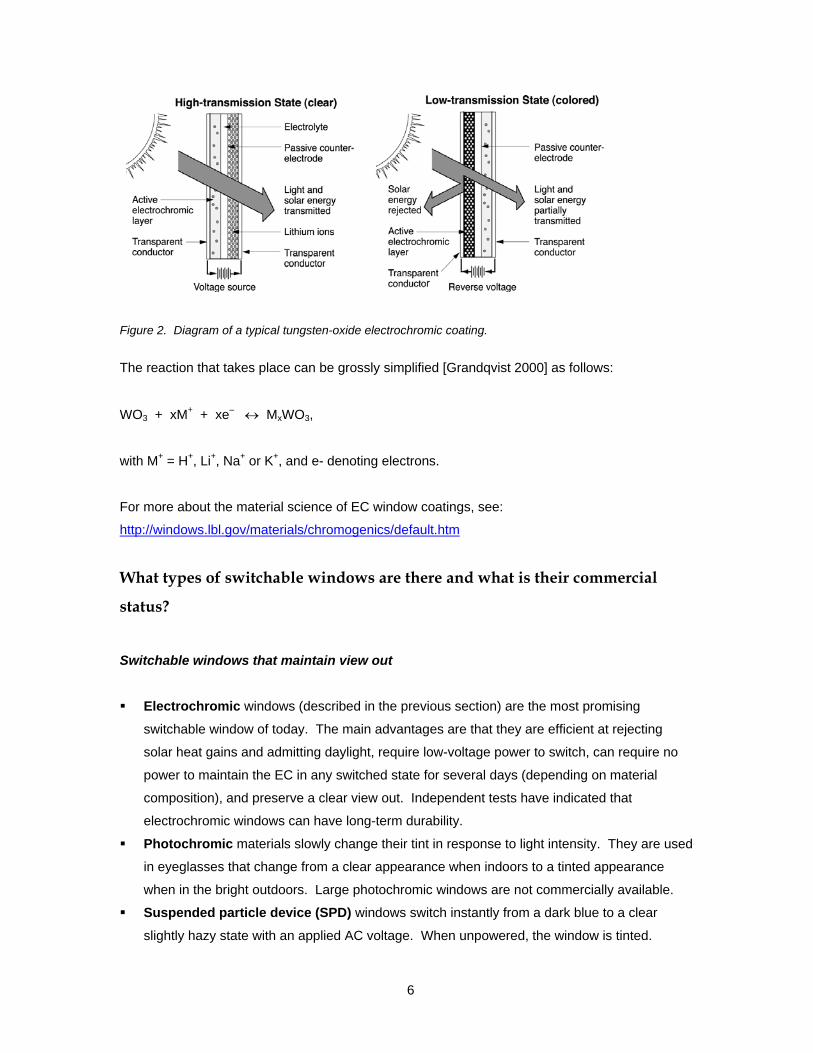
An EC coating is a nanometer-thick (1x10⁻⁹ m, 4x10⁻⁸ inch), multi-layer film or stack deposited on
a glass or plastic (Figure 2). Transparent conductors form the outer layers of the stack, an active
electrochromic and passive counter-electrode layer form the middle layers, and an ion-conducting
electrolyte layer forms the center portion of the stack. The system works like a battery. A bipolar
potential is applied to the outer transparent conductors, which causes lithium ions to migrate
across the ion-conducting layer from the counter-electrode layer to the electrochromic layer. A
reversible electrochemical reaction takes place causing a tinted Prussian Blue appearance.
Reversing the potential causes the ions to migrate back, causing a bleached clear appearance.
The material and physical composition of the EC window can vary and these dictate the unique
properties of the EC window: its switching range, speed versus temperature characteristics,
power consumption when being switched, durability, and color.
6
Figure 2. Diagram of a typical tungsten-oxide electrochromic coating.
The reaction that takes place can be grossly simplified [Grandqvist 2000] as follows:
WO3 + xM+ + xe– ↔ MxWO3,
with M+ = H+, Li+, Na+ or K+, and e- denoting electrons.
For more about the material science of EC window coatings, see:
http://windows.lbl.gov/materials/chromogenics/default.htm
What types of switchable windows are there and what is their commercial
status?
Switchable windows that maintain view out
Electrochromic windows (described in the previous section) are the most promising
switchable window of today. The main advantages are that they are efficient at rejecting
solar heat gains and admitting daylight, require low-voltage power to switch, can require no
power to maintain the EC in any switched state for several days (depending on material
composition), and preserve a clear view out. Independent tests have indicated that
electrochromic windows can have long-term durability.
Photochromic materials slowly change their tint in response to light intensity. They are used
in eyeglasses that change from a clear appearance when indoors to a tinted appearance
when in the bright outdoors. Large photochromic windows are not commercially available.
Suspended particle device (SPD) windows switch instantly from a dark blue to a clear
slightly hazy state with an applied AC voltage. When unpowered, the window is tinted.

7
When powered (100 V AC or 0.05-0.5 W/ft2 of glass), the window can be set to any
intermediate state between clear and fully colored. The SPD window is laminated, can be
fabricated in up to 4x8 feet sheets, and is offered in curved and flat shapes. Long-term
durability (e.g., greater than 3-5 years) has not been independently verified so this window
type is not promoted in this guide. This product is commercially available (e.g., ThermoView
AlterLite windows).
Switchable windows that don’t maintain view
Thermochromic materials slowly change from a clear state when cold to a more diffuse,
white translucent state when hot. Prototype windows have been tested but are not
commercially available.
Liquid crystal device windows are translucent when in an unpowered state and become
instantly clear (with a noticeable haze) when power is applied. Power must be applied
continuously for the window to remain clear (24-100 V AC or 0.5 W/ft2 of glass). The window
has a high daylight and solar heat gain transmittance and is therefore of limited use in
commercial buildings. The window is commercially available. While typically used for high-
end interior applications, ultraviolet (UV)-stable formulations now permit exterior applications
but the cost remains high.
Reflective hydride window coatings are a relatively new type of electrochromic device that
switches from a transparent to a reflective appearance with the injection of hydrogen gas.
This coating is still in the R&D stage. More information can be found at:
http://windows.lbl.gov/materials/chromogenics/default.htm
This guide focuses on tungsten-oxide (WO3) EC windows such as that produced by SAGE
Electrochromics, Inc. At the time this guide was produced (Spring 2006), this type of EC window
was only just introduced by SAGE Electrochromics, Inc. (an all solid state lithium based WO3
device) to the commercial market in sizes of up to 42.5 by 60 inches with on-off control (fully
bleached and fully colored states only). Products from other manufacturers may enter the market
shortly. An EC window product was offered in Germany by Flabeg GmbH & Co. (polymer-
laminated WO3 device) in 1997 in sizes up to approximately 3x6 feet with intermediate-state
controls (ability to modulate the EC window to any tinted state) but is no longer available (for
unknown reasons).

8
What do electrochromic windows look like?
The EC window tint varies from a clear to a deep Prussian Blue. At any switched state, EC
windows provide an undistorted view out with no haze. From the exterior, the clear state can look
slightly yellow to green under dim conditions (depending on EC type and age), while the darkest
tinted state can look almost like a black spandrel panel under bright conditions. Early-market
prototypes were tested in the field (Figures 3-4 below) and these exhibited a slight pink to
yellowish non-uniform reflectance. There were also a few minute pinholes (stays clear when
switched). These colors and non-uniformity are not expected to occur with commercially
available products (e.g., new SAGE windows will switch from a slight clear green to dark blue).
The EC window is sold as a dual-pane insulating glass unit (IGU). In the following photographs,
the IGU was composed of two clear glass window layers with the EC coating on the inside
surface of the exterior layer (#2 surface).
Figure 3. Exterior views of prototype EC windows at the fully tinted state (left and right photos) and a conventional spectrally-selective Azurlite window with interior Venetian blinds on the far right.

9
Figure 4. Interior views of the EC window wall with a) EC window at darkest, intermediate, and clearest states during the day (left) and b) EC window at its darkest state at night (right). The LBNL-installed sensors on the glass are not part of the EC product.
Appearance when switching
When the EC window is not being switched (“at rest”), the window tint is uniform across the IGU.
When the EC window is in the process of being switched, the window tint is non-uniform. The
edges where the bus bars are located switch faster than the center of the window (Figure 5).
a
b
c
d
Figure 5. Appearance of the EC window when switching from clear (a) to tinted (d). The bus bars are located on the top and bottom edges so the tinting occurs faster at these edges while the middle portion is tinted more slowly. When switched in the reverse direction, the edges bleach more quickly while the middle portion clears more slowly.
10
Note: Electrical potential is applied to thin metal strips located at opposite edges of the IGU and
these are called “bus bars”.
Appearance of a multi-pane window wall
When a window wall is composed of multiple, immediately adjacent EC windows, color matching
is important for the aesthetics of the facade. If adjacent EC windows do not match, the façade
can have a slight to noticeable checkerboard appearance.
One manufacturer produced a control system that enables between-window color matching at not
only the end states (fully bleached or tinted) but also at any intermediate tinted state (this product
is no longer commercially available). Other manufacturers are working to develop such
capabilities. Color matching could drift over time and may need to be corrected slightly with
software adjustments every few years, depending on how the manufacturer has implemented
transmittance control.
When switching, the tint of side-by-side EC windows may not match because the rate of switching
is dependent on the surface temperature of the EC window and these could differ if some window
units are shaded while others are not (e.g., window with an overhang). If different size window
units are used, the larger units will switch slower than the smaller units.
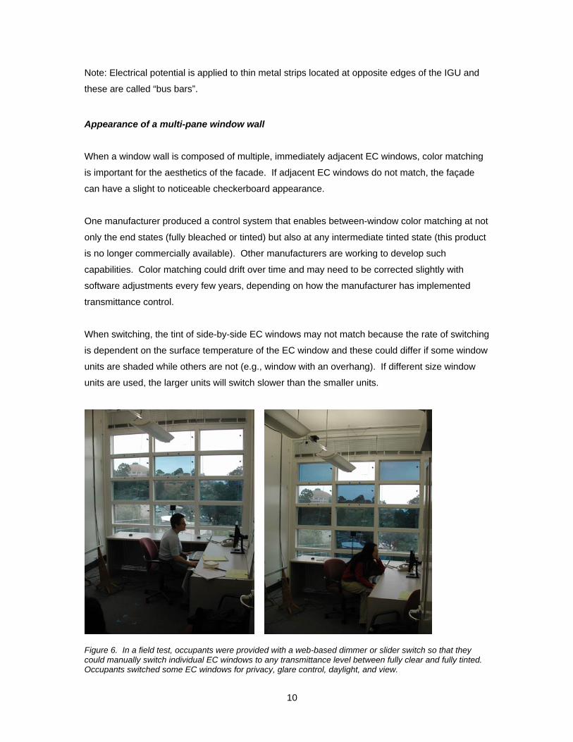
Figure 6. In a field test, occupants were provided with a web-based dimmer or slider switch so that they could manually switch individual EC windows to any transmittance level between fully clear and fully tinted. Occupants switched some EC windows for privacy, glare control, daylight, and view.

11
Given individual pane control, patterns of various tint levels could be deliberately created by the
occupants or the architect in response to dynamic conditions (Figure 6) or other control criteria
(signage, etc.).
What is the switching range of electrochromic windows?
The visible transmittance (Tv) and solar heat gain coefficient (SHGC) range of EC coatings vary
depending on the material composition. U-factor is not affected by the change in tint. Generally,
the wider the switching range, the more control one has under variable sun and sky conditions:
A high-transmittance clear state lets in more daylight when it is overcast or early morning
or late afternoon.
A dark-transmittance colored state reduces interior window and surface brightness that
can cause visual discomfort. A transmittance of less than Tv<0.001 is needed to reduce
the brightness of the sun orb down to comfortable levels.
Generally, commercial buildings in the U.S. tend to be internally-load dominated buildings
due to their high occupant and equipment density and operate in a cooling mode even
during the winter. For these types of buildings, the SHGC range should be as low as
possible compared to the Tv range.
Whether the windows are small or large, a wide switching range is important.
The EC window is sold as a dual-pane insulating glass unit (IGU) where the EC coating is applied
to the inside surface of the exterior glazing layer. The window’s overall switching range is
determined not only by the EC coating but also the glass layers of the IGU. The exterior glazing
layer (or substrate) itself can be tinted or clear. The interior glazing layer can be any type of glass
(tinted, low-e coated, fritted, etc.). An example of center-of-glass EC window properties if both
layers of the IGU are clear glass is as follows:
Tv=0.60-0.05
SHGC=0.48-0.09
U-factor=1.59-1.87 W/m2-ºC (0.28-0.33 Btu/h-ft2-ºF) with 90%-argon or air fill,
respectively. The U-factor stays constant irrespective of switching level.
The emittance of the EC glazing layer was assumed to be 0.84 on the exterior uncoated
surface and 0.15 on the interior coated surface.
Switching ranges can be computed using the WINDOW5 software and spectral data. See more
about EC window system design in the section “Design”.

12
How fast do electrochromic windows switch?
Switching speed varies with the size and exterior surface temperature of the EC window (which is
dictated by incident solar radiation levels, wind speed, and air temperature):
If the window area is small, the EC will switch faster because the distance between the bus
bars is small. For example, for an18-inch distance between bus bars, the fastest switching
time is between 1-4 minutes under sunny and/or hot conditions.
• For larger windows, switching time can be significantly longer. Faster switching of large-area
EC glass is achieved by applying additional thin conductor line(s), thus allowing for faster
distribution of the electrical current over the EC pane. An additional conductor also allows for
the possibility of independent control of segments within a larger pane offering the potential
for implementing more optimal daylighting strategies. Larger EC panes with additional
conductors are offered by SAGE Electrochromics, Inc.
If the window is hot due to high ambient air temperatures and/or because sunlight is striking
the facade, the EC will switch faster. When tinted, the EC absorbs solar radiation, which then
raises its surface temperature and increases switching speeds. Under cold conditions when
solar radiation levels are low (e.g., early morning or cloudy sky conditions), the EC can take a
long time to switch from fully bleached to fully colored.
When switching from clear to fully tinted, speeds are fast in the beginning, then slower toward
the end (Figure 7). If cold, the EC can switch approximately 80% of its full switching range
quickly, then take a long time to reach the last approximately 20% of full tinting (i.e.,
exponential function). For example, for an 35x18-inch tungsten-oxide EC window, these
switching times were measured in the field (18-inch distance between bus bars):
When the EC surface temperature is greater than approximately 10ºC (50ºF), switching
speeds are less than 6-7 minutes. Under sunny, warm conditions, switching speeds can
be less than 4 minutes.
If the EC surface temperature is between –3ºC to –1ºC (27-30ºF), it can take 37 minutes
to color or bleach between a visible transmittance (Tv) of Tv=0.56 and Tv=0.13 (Figure
7). It can take even longer to get down to its minimum transmittance (Tv=0.05). The
lower transmittance, darker tint levels are useful if the EC window is being used to control
window glare and direct sun. With low switching speeds, occupants will most likely need
to resort to using interior blinds to block low angle direct sun from their field of view.

13
4
8
12
16
20
24
28
32
36
40
44
48
52
56
60
64
68
72
0.0 0.5 1.0 1.5 2.0 2.5 3.0 3.5 4.0 4.5 5.0 5.5 6.0 6.5 7.0 7.5 8.0 8.5 9.0
Hour
Tv
x=8.25, y=21.5 x=8.25, y=12 x=8.25, y=6
Figure 7. EC transmittance versus time, or switching speed of a 35x18-inch device (18-inch between bus bars) with an average EC surface temperature of –3°C (27°F). Each transmittance sensor was 0.21 m (x=8.25 inches) from the bus bar edge but at various distances from the non-bus-bar edge (y dimension in legend (inches)). Transmittance levels are not expected to match when in the process of switching.
Under what temperatures will electrochromic windows operate?
LBNL and NREL have cycled EC windows between bleached and colored states within a surface
temperature range of –10˚C to 95˚C (14-203ºF). EC switching speeds slow down considerably at
the lower temperatures as noted above.
In terms of actual operating conditions, the surface temperature of EC windows will not reach
levels of 95˚C (203ºF) in typical vertical window and skylight applications. SAGE
Electrochromics, Inc. monitored EC surface temperatures of up to 76ºC in various outdoor
applications (Arizona desert, sloped skylights facing south, etc.). LBNL measured exterior glass
surface temperatures for an EC IGU with clear glass substrates of up to 65ºC on sunny days for a
south-facing vertical EC window in Berkeley, California.
The exterior surface temperature of EC windows can get quite hot because the EC window
absorbs solar radiation when it’s tinted. With a low-e coating and insulating glass unit
composition, the interior surface temperature of the window can be near ambient room air
temperatures. Exact values can be computed using the WINDOW5 software. Without a low-e
coating, EC windows could cause considerable thermal discomfort.

14
What are the power consumption levels of EC windows?
Low-voltage power is required to switch EC windows and for some types of windows, a small
applied voltage is needed to keep the EC in a constant state, irrespective of the level of tint. For
example:
The polymer laminated WO3 EC window requires power only when switching the EC window
to a different level of tint; without power, the EC tint remains at the same level of tint for
several days.
SAGE Electrochromic’s window requires constant power – the following are monitored power
consumption levels (end use power at the wall outlet) for an array of (15) 35x18 inch windows
tested in the field (18-inch distance between bus bars); power levels are likely to scale with
window area:
If no power is applied, the EC window “rests” at the clear state. The level of tint at the
clear state will vary slightly between windows (e.g., Tv=0.60-0.70) and may be
discernable when comparing two side-by-side windows. The EC window can be left
unpowered during the night.
If the EC window is in the process of being switched, peak power consumption is 0.26-
0.32 W/ft2-glazing (5-6 W for a 42.5x60 inch EC window).
If the EC is being held constant at any level of tint, steady-state power consumption is
0.07-0.15 W/ft2-glazing (1.2-2.6 W for a 42.5x60 inch window), assuming a 1-to-1
relationship between the EC window unit and its window controller. This includes power
to the window, electronic circuitry for control, and parasitic losses due to the efficiency of
the power supply.
Average daily power consumption of the EC system (window+controller+power supply)
during a 12-hour day was monitored to be the same as steady-state power levels in the
bullet above. These consumption levels can be reduced to 25-30% of current levels, if
the control circuitry and power source are designed more efficiently.
How long will EC window coatings last?
Long-term EC window durability has been evaluated by the National Renewable Energy
Laboratory (NREL) under steady state environmental conditions defined by the ASTM Standard
E2141-02. The ASTM standard requires that the EC window be cycled between its maximum
visible (photopic) transmittance and at least one-fourth of the maximum transmittance state while
the EC windows are irradiated with a minimum of a 1.0 UV-sun equivalent (of an AM 1.5 global
solar spectrum) under controlled conditions (elevated temperature of 85ºC (185ºF)). NREL has
successfully cycled SAGE EC windows between maximum and one-fifth of the maximum state

15
(e.g., Tv=0.60-0.12) for over many tens of thousands of cycles. Long-term durability has not yet
been assessed by a third party under outdoor field conditions where the EC window is cycled
between maximum bleached and colored states (e.g., Tv=0.60-0.05).
EC window coatings are somewhat analogous to batteries. Over time, one may lose a small
fraction of the full switching range of the EC window or it can develop catastrophic cosmetic
defects. It is unknown what factors contribute to acceleration of degradation. Using the ASTM
Standard E2141-02, NREL has cycled some EC windows between bleached and colored states
for tens of thousands of cycles (full bleach to full color then back again) and has measured no
significant loss in the switching range of the EC window, nor any cosmetic deterioration.
For more information on electrochromic window durability, see
http://www.nrel.gov/buildings/windows/durability.html

16
Designing Electrochromic Windows for Buildings
What are the basic components that make up an electrochromic window?
Note in the “About the Electrochromic Window Technology” section, the terms “window” and
“insulating glass unit” are used rather loosely. An electrochromic window, to be specific, is
composed of an insulating glass unit (IGU) and window frame. The EC insulating glass unit
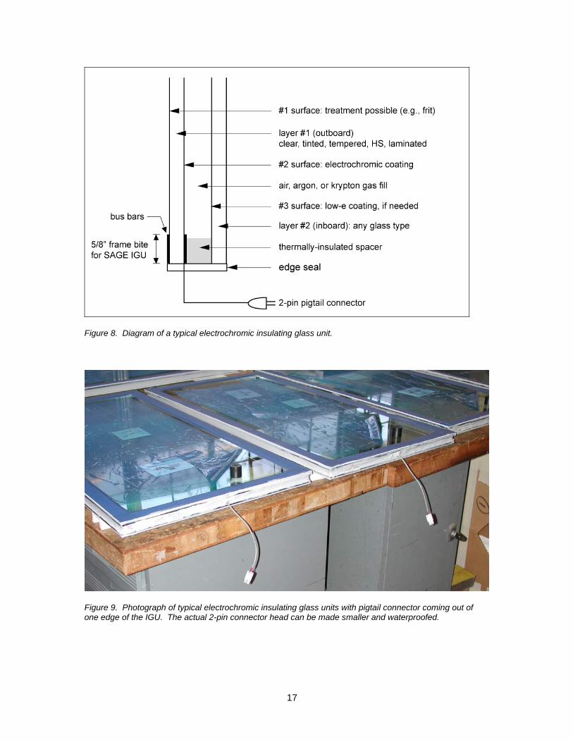
(Figure 8) is composed of two panes or layers of glass assembled with a spacer, then sealed on
all four edges, where the exterior glass layer has the EC coating on the second, #2 interior-facing
surface (glass surfaces of a window are numbered from the exterior to interior). The following
describes what is feasible with EC IGUs, not necessarily what is commercially available at this
time:
The exterior layer of glass (or “substrate” on which the EC coating is deposited) can be
tinted. If this substrate is heavily tinted, the tint plus EC coating at its tinted switched
state will increase thermal stress and the likelihood of glass breakage.
The exterior substrate can have a surface treatment (e.g., frit) on the exterior #1 surface
but not on the interior #2 surface with the EC coating.
The exterior substrate can be of any type of glass (e.g., laminated, tempered, heat-
strengthened, etc.), but it will most likely be tempered or heat-strengthened because the
EC in its tinted state increases thermal stress. Lamination is possible, but lamination will
eliminate the low-e properties of the EC coating (if it has such properties).
The exterior glazing layer will have metallic printed bus bars located on two parallel
edges. A 2-conductor wire will extend from this edge and terminate in a 2-pin pigtail
connector (approximately 5 to 10 inches in length).
The interior layer of glass can be any type of glass. If the EC coating does not have low-
emittance properties (e.g., e≤0.15), then the interior layer should have a low-e coating.
For the IGU assembly, the low-e coating should be on the #3 surface to reduce heat
transfer to the interior.
Gas fill between the two panes can be of any type of gas fill; i.e., air or an inert gas such
as argon or krypton.
Spacers should be insulated to prevent thermal conduction and condensation.
A proper edge seal is important. EC coatings degrade rapidly if water vapor is allowed to
enter into the between-pane air gap. The IGU industry is mature, so seal failure is rare
and unlikely to occur, according to industry experts.
17
Figure 8. Diagram of a typical electrochromic insulating glass unit.
Figure 9. Photograph of typical electrochromic insulating glass units with pigtail connector coming out of one edge of the IGU. The actual 2-pin connector head can be made smaller and waterproofed.

18
What sizes and shapes do electrochromic windows come in?
Emerging EC window products are likely to come in limited sizes and shapes in order to keep
costs down. EC windows are available in flat rectangular shapes. Flat, irregular shapes could be
produced but are likely to be very costly.
At present, SAGE Electrochromics, Inc. is the only supplier of electrochromic insulating glasss
units (see Resources/ Industry Contacts). They supply insulating glass units in sizes of up to
42.5 by 60 inches for skylight and window applications.
EC glass cannot be cut then installed in window frames in the field (as one can do with monolithic
clear glass, for example). EC glass must be part of a sealed insulating glass unit assembly.
Therefore, sizes must be pre-determined prior to shipment and installation in the field.
Are there special considerations for the framing system?
For residential and small commercial applications, EC windows and skylights will likely be
shipped as a factory-built framed unit, as is typical of most residential windows. Low-voltage
wiring details for operable units will be handled differently by each manufacturer. Consult the
product specifications to better understand installation issues.
For commercial buildings with curtainwall framing systems, consult with EC window and framing
manufacturers to determine how the EC window should be accommodated in the framing and
how the low-voltage wiring from the EC window should be routed through the framing system.
As an example, LBNL worked with Wausau Window and Wall systems to specify a site-built
curtainwall framing system for our field test facility.
All windows were non-operable.
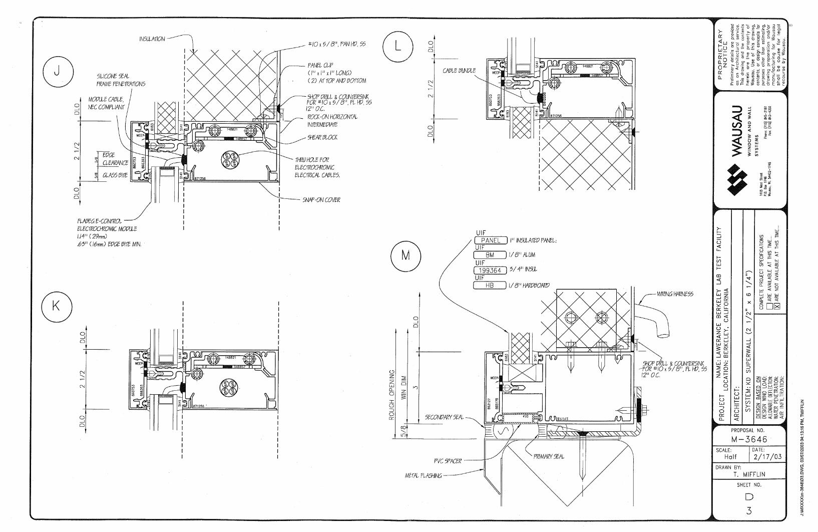
A 3-inch wide framing system was required to meet the minimum edge clearances and
accommodate earthquake conditions: expect thermal expansion with these highly absorptive
EC windows. A 2-inch or 2.5-inch curtainwall system could be used, according to SAGE, with
sufficient edge clearance and room for their connector and wiring.
A 5/8-inch frame bite is needed to cover the SAGE IGU edge, since the EC coating does not
extend all the way to the edge. If the edge is exposed, the uncoated glass will be exposed
and direct sunlight could pass through and cause glare.
The windows were glazed from the exterior. An interior glazed framing system may be
preferred to ensure dry conditions for the wiring in the glazing pocket, to facilitate window
19
replacement, and ease troubleshooting of the wiring system (no wiring problems occurred
over the installed 3-year term despite a few minor earthquakes!).
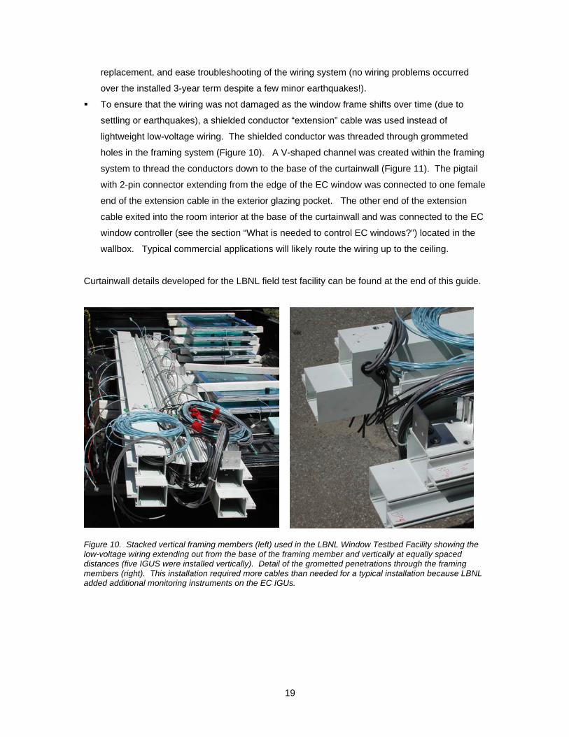
To ensure that the wiring was not damaged as the window frame shifts over time (due to
settling or earthquakes), a shielded conductor “extension” cable was used instead of
lightweight low-voltage wiring. The shielded conductor was threaded through grommeted
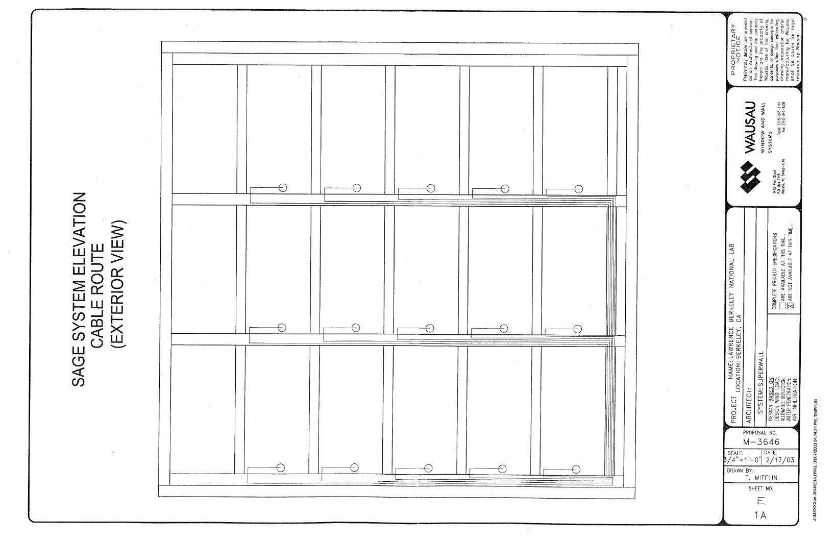
holes in the framing system (Figure 10). A V-shaped channel was created within the framing
system to thread the conductors down to the base of the curtainwall (Figure 11). The pigtail
with 2-pin connector extending from the edge of the EC window was connected to one female
end of the extension cable in the exterior glazing pocket. The other end of the extension
cable exited into the room interior at the base of the curtainwall and was connected to the EC
window controller (see the section “What is needed to control EC windows?”) located in the
wallbox. Typical commercial applications will likely route the wiring up to the ceiling.
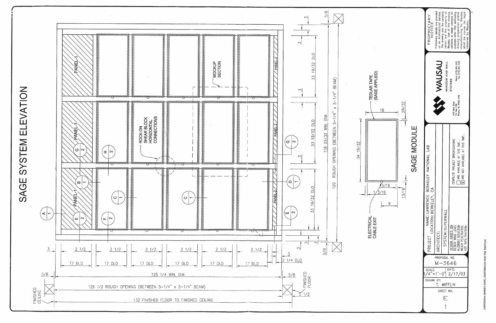
Curtainwall details developed for the LBNL field test facility can be found at the end of this guide.
Figure 10. Stacked vertical framing members (left) used in the LBNL Window Testbed Facility showing the low-voltage wiring extending out from the base of the framing member and vertically at equally spaced distances (five IGUS were installed vertically). Detail of the grometted penetrations through the framing members (right). This installation required more cables than needed for a typical installation because LBNL added additional monitoring instruments on the EC IGUs.

20
Figure 11. V-channel used to thread cabling through the vertical framing members (left). LBNL installation of EC windows using an exterior-mounted curtainwall system (right).
Factory-built, unitized curtainwall systems could solve some of the trade and labor union issues
associated with electrochromic windows. Electricians will likely claim the tasks of pulling wiring
through the framing system and connecting the EC window in the glazing pocket, conflicting with
the curtainwall contractor.
What is needed to control electrochromic windows?
Two-state control (fully bleached or fully colored)
EC windows will typically be sold with a manually operated switch that allows the occupant to
change the tint level of the window between fully bleached and fully colored. For example, SAGE
Electrochromics provides a wall mounted on-off switch with LED lights that blink to indicate when
switching is occurring. For a previously offered product with intermediate-state control, a push-
button controller was mounted near the window wall. A user could push an up or down button to
set the window to one of five different tint levels. LED lights for each of the tint levels would blink
while switching, stop when completed switching, then turn off after several minutes. For
networked systems, each EC window or set of windows could be controlled via a PC desktop
user interface, as was done in the LBNL field tests.
EC window controllers (i.e., integrated circuit (IC) boards) are required to switch the windows.
The EC controller regulates the current and voltage delivered to each window. For on-off control,
a single multiplexed EC controller may be used to operate multiple windows.
21
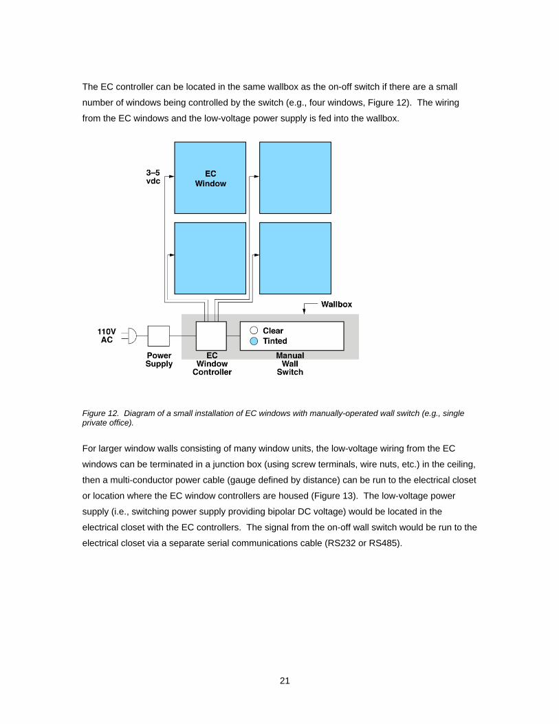
The EC controller can be located in the same wallbox as the on-off switch if there are a small
number of windows being controlled by the switch (e.g., four windows, Figure 12). The wiring
from the EC windows and the low-voltage power supply is fed into the wallbox.
Figure 12. Diagram of a small installation of EC windows with manually-operated wall switch (e.g., single private office).
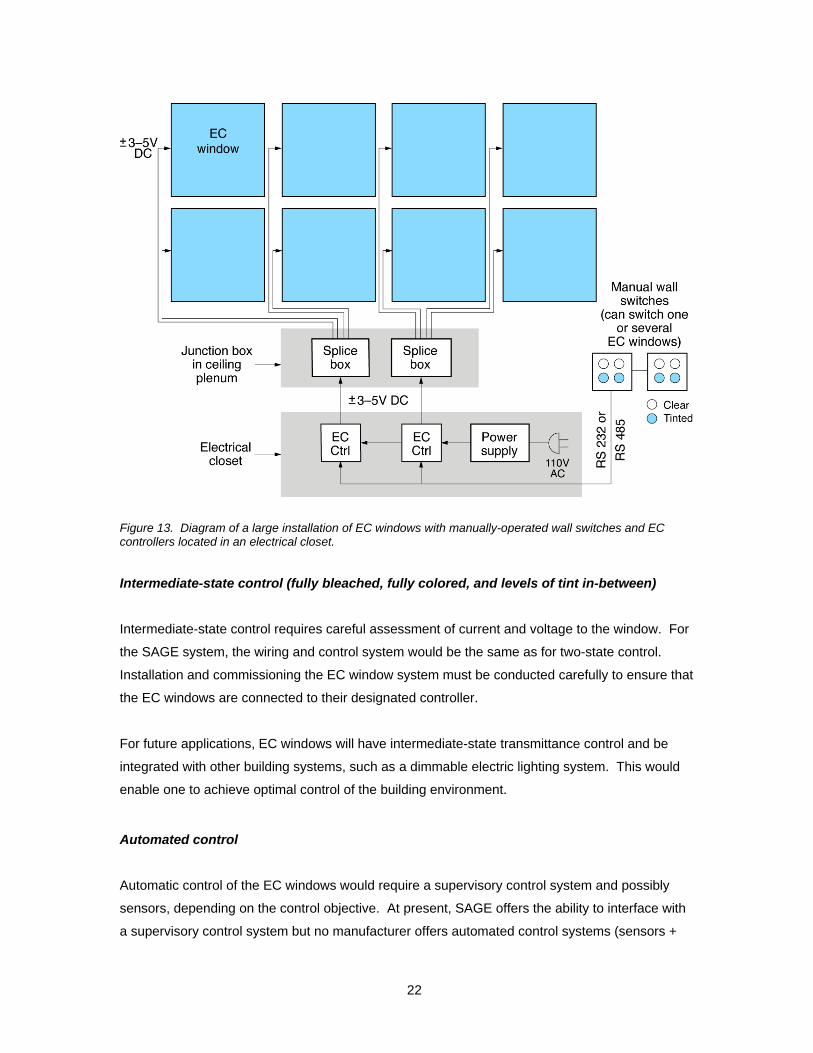
For larger window walls consisting of many window units, the low-voltage wiring from the EC
windows can be terminated in a junction box (using screw terminals, wire nuts, etc.) in the ceiling,
then a multi-conductor power cable (gauge defined by distance) can be run to the electrical closet
or location where the EC window controllers are housed (Figure 13). The low-voltage power
supply (i.e., switching power supply providing bipolar DC voltage) would be located in the
electrical closet with the EC controllers. The signal from the on-off wall switch would be run to the
electrical closet via a separate serial communications cable (RS232 or RS485).
22
Figure 13. Diagram of a large installation of EC windows with manually-operated wall switches and EC controllers located in an electrical closet.
Intermediate-state control (fully bleached, fully colored, and levels of tint in-between)
Intermediate-state control requires careful assessment of current and voltage to the window. For
the SAGE system, the wiring and control system would be the same as for two-state control.
Installation and commissioning the EC window system must be conducted carefully to ensure that
the EC windows are connected to their designated controller.
For future applications, EC windows will have intermediate-state transmittance control and be
integrated with other building systems, such as a dimmable electric lighting system. This would
enable one to achieve optimal control of the building environment.
Automated control
Automatic control of the EC windows would require a supervisory control system and possibly
sensors, depending on the control objective. At present, SAGE offers the ability to interface with
a supervisory control system but no manufacturer offers automated control systems (sensors +

23
control smarts). Application software could be developed by the building engineering or controls
team. A transmittance value would be computed by the supervisory control system software then
sent as a command to the EC window controller, similar to the on-off switch. The supervisory
control system could be an independent proprietary EC control system or be interfaced with other
proprietary building control systems (lighting, HVAC, etc.) via a gateway link. A manually-
operated keypad located within the space should be provided to enable override of the automatic
system. LBNL devised an integrated EC window and daylighting control system. This system is
described in the project’s final report.
Single- versus grouped window control
For a window wall composed of multiple window units, individual EC windows could be controlled
separately (Figure 6, 14 and 15). If the window wall is composed of four windows, for example,
the wall-mounted on-off switch would have four switches with proper labeling so that the user
could ascertain window position. Individual windows could also be grouped into zones so that all
the windows in the upper row, for example, could be controlled separately from all the windows in
the lower row. If the windows are controlled via a network, window grouping could be
reconfigured in software as space changes are made, as opposed to physical re-wiring.
Figure 14. Diagram showing a zoned window wall.

24
Do EC windows need to be commissioned after installation?
Commissioning should be done typically by the window contractor or manufacturer prior to
building occupancy. This ensures that the system is operating as intended in the specifications.
For manually-operated systems:
Verify that the windows are operating properly.
Verify that the on-off switches are labeled so that it is clear which switch controls which
window or group of windows.
For automated systems and those with intermediate-state control, more extensive tests will be
required to commission the window system.
What are the maintenance requirements of EC windows?
If the EC windows are operating properly, the windows require the same maintenance as
conventional windows.
If the EC windows are not operating properly due to electrical problems, the system should be
diagnosed to determine if there are any loose or broken connections, problems with any of the
electrical components, or problems with the EC windows themselves.
Are there any CSI specifications developed for EC windows?
Consult SAGE Electrochromics website. They have some downloadable specifications that detail
their product line. There are no other specifications available from other manufacturers at this
time.
Will EC windows have NFRC labels?
All windows sold in California (and many sold in other states) must be labeled with a standardized
National Fenestration Rating Council (NFRC) window label. The Dynamic Glazings committee of
NFRC has recently adopted technical rating and certification procedures that will enable
manufacturers to rate products in 2006 with whole-window Tv and SHGC switching ranges

25
(values in fully bleached or fully colored states). These values will appear on the label, providing
the specifier and consumer with information to compare EC window products.
There are a number of additional issues of interpretation that need to be addressed as the labels
come into use. For example, in terms of complying with Title 24, which of several label values
(fully colored, fully bleached, or intermediate values?) should be used to assess compliance with
both prescriptive and performance based implementations of Title 24? The operation of the EC
window AND its switching range dictate its energy-efficiency in buildings. LBNL is involved with
the manufacturers and with NFRC on these issues, so that when products begin to be specified in
2006 they can be addressed by code officials.
How are dynamic windows accommodated in Title-24 and ASHRAE 90.1?
At present, the code does not provide energy credits for manually-operated interior shades and is
unlikely to provide credits for a manually-operated electrochromic window. For automated
shades and EC windows, the prescriptive method could be used to obtain energy credits if the
automated systems cannot be manually overridden by the occupants. This leads to problems
with occupant acceptance and can slow the rate of market adoption. Better compliance methods
should be developed for dynamic windows.
26
Performance Benefits of Using Electrochromic Windows
What are the benefits of using EC windows?
For EC windows with intermediate-state control, which may be commercially available in the next
several years, LBNL quantified the energy and non-energy benefits of automated EC windows
that are integrated with daylighting control systems (dims lights as daylight increases). With on-
off control, the benefits will be similar but likely of lesser magnitude:
Significantly greater access to outdoor views.
Reduced need to use blinds and shades.
Significant lighting energy use savings if the window is zoned and controlled properly.
Significant cooling load savings, depending on the usage patterns of manually-operated
interior shades.
Significant peak demand reductions.
Reduction of required HVAC capacity due to reduced peak loads.
Enables active load management, demand side management and demand response
under peak load conditions.
These benefits were quantified for commercial buildings with vertical windows and principally for
office buildings where occupants will draw blinds and shades in order to perform computer-based
and other work tasks more comfortably.
For residential applications, consult the “Resources” section for more information.
What are the energy benefits of using EC windows?
To achieve significant energy savings while meeting visual comfort requirements in typical
commercial office buildings, the EC window wall should be zoned (Figure 15) and controlled with
intermediate-state control to balance daylight and glare. A Venetian blind should be combined
with the EC window to block direct sun if a) the occupant’s field of view combined with window
orientation and design causes frequent views of the sun orb, b) if the minimum transmittance of
the EC window is greater than approximately Tv=0.03, and c) if cold weather combined with
partly cloudy conditions cause the EC window to switch to this lowest state more slowly than
desired by the occupant (see “What do people think of EC windows: About visual comfort”).

27
Figure 15. Radiance simulation of a south-facing private office at 11:30 on a clear winter solstice day. This image illustrates the EC control algorithm for visual comfort. Direct sun is blocked from the occupant’s field of view by the upper zone’s Venetian blind (a) or by an overhang (b). This upper EC zone (b) is controlled to admit daylight. The lower EC zone (c) is switched to Tv=0.05 to minimize luminance contrasts between the VDT (e2) and sunlit (e1, d1) surfaces and between paper-based tasks that are sunlit (d1) and shadowed (d2). The luminance of the lower window is controlled (c). View out is preserved (c).
With the zoned EC window configuration described above (but no overhang), a full-scale
monitored field test of a zoned EC window with a visible transmittance (Tv) range of Tv=0.60-0.05
yielded the following results:
Average daily lighting energy use savings in a private south-facing office in Berkeley,
California were 10-23% given non-optimized glare/daylight control, compared to a
conventional high-transmittance window (Tv=0.60) with a fully-lowered, slightly open
Venetian blind (comparable level of glare control to EC window) with the same
daylighting control system.
Savings of 44% are attained if the reference case has no daylighting controls, as is the
norm in building practice today.
Cooling savings were small with this comparison, but could be increased if the EC
windows are controlled based on occupancy (e.g., Tv=minimum if unoccupied for a
certain period – but switching speeds would need to be taken into account).
a
b
c
d1d2
e1e2
a
b
c
d1d2
e1e2
28
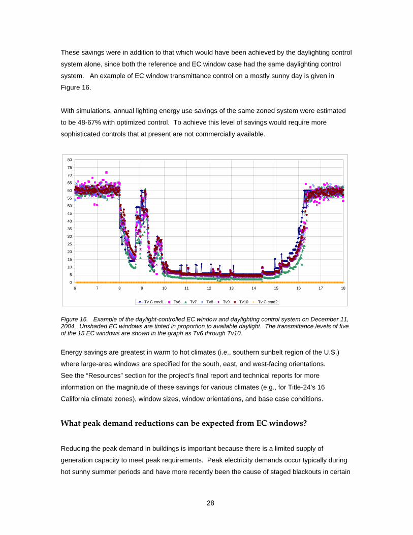
These savings were in addition to that which would have been achieved by the daylighting control
system alone, since both the reference and EC window case had the same daylighting control
system. An example of EC window transmittance control on a mostly sunny day is given in
Figure 16.
With simulations, annual lighting energy use savings of the same zoned system were estimated
to be 48-67% with optimized control. To achieve this level of savings would require more
sophisticated controls that at present are not commercially available.
0
5
10
15
20
25
30
35
40
45
50
55
60
65
70
75
80
6 7 8 9 10 11 12 13 14 15 16 17 18
Tv C cmd1 Tv6 Tv7 Tv8 Tv9 Tv10 Tv C cmd2
Figure 16. Example of the daylight-controlled EC window and daylighting control system on December 11, 2004. Unshaded EC windows are tinted in proportion to available daylight. The transmittance levels of five of the 15 EC windows are shown in the graph as Tv6 through Tv10.
Energy savings are greatest in warm to hot climates (i.e., southern sunbelt region of the U.S.)
where large-area windows are specified for the south, east, and west-facing orientations.
See the “Resources” section for the project’s final report and technical reports for more
information on the magnitude of these savings for various climates (e.g., for Title-24’s 16
California climate zones), window sizes, window orientations, and base case conditions.
What peak demand reductions can be expected from EC windows?
Reducing the peak demand in buildings is important because there is a limited supply of
generation capacity to meet peak requirements. Peak electricity demands occur typically during
hot sunny summer periods and have more recently been the cause of staged blackouts in certain

29
regions of California. There is significant pressure in states like California and New York to avoid
building new power generation facilities to meet growing peak requirements. Developing active
load management and demand responsive technologies and control strategies can help in this
regard. Consumers can also derive significant utility cost reductions if such load shed capabilities
are available in their building.
Solar heat gains and lighting energy use constitute a significant percentage of a commercial
building’s perimeter zone peak load. Peak cooling load reductions and therefore peak demand
reductions can be significant because the EC window can substantially reduce solar heat gains
when switched to its maximum colored state.
Referring to the LBNL field test data and given that measurements were made for a south-facing
window orientation, the peak condition occurs on a clear winter day when solar irradiance levels
are the highest of the year. Peak cooling load reductions due to solar heat gains were a maximum
of 26% and 19% compared to an unshaded and fully shaded reference case if the EC window is
controlled to its most colored state (solar heat gain coefficient (SHGC)=0.09; Figure 17).
Reference with no blind Reference with blind
Case 2: EC glare dg5 no blind; Ref no blind
0
400
800
1200
1600
2000
0 400 800 1200 1600 2000Reference Case (W)
Test
cas
e (W
)
Case 5: EC glare dg5 no blind; Ref blind
0
400
800
1200
1600
2000
0 400 800 1200 1600 2000Reference Case (W)
Test
cas
e (W
)
Figure 17. Field measured hourly peak cooling load due to heat gains from window and lights for the single-zone EC system controlled by glare (Tv=0.05) compared to the reference case with (right) or without (left) fully-lowered Venetian blinds (45° slat angle). Peak loads occurred above the 800-1000 W level for both the reference and test (EC window) cases. [Lee et al. 2006]
Lighting peak demand reductions depend on the assumptions for the reference case. If the
reference case’s window is large, has high-transmittance glazing, and has the same daylighting
controls as the EC case, then peak lighting load reductions are likely to be very small or zero. If

30
the base case has no lighting controls, peak demand reductions could be 70-100%, depending on
the minimum or standby requirements of the test case’s dimming electronic ballast.
Peak demand reductions are greatest in warm to hot climates (i.e., southern sunbelt region of the
U.S.) where large-area windows are specified for the south, east, and west-facing orientations.
See the “Resources” section for the project’s final report and technical reports for more
information on the magnitude of these savings for various climates (e.g., for Title-24’s 16
California climate zones), window sizes, window orientations, and base case conditions.
What HVAC capacity reductions can be expected from EC windows?
Conventional commercial building heating, ventilation, and air-conditioning systems are sized
based on the peak cooling load in the building. The capacity of the chiller system, for example,
can be reduced if EC windows are automated, lowering the capital cost of the building.
For more advanced low-energy cooling strategies or for buildings located in the northern region of
the U.S., installation of an air-conditioning (AC) system may be avoided altogether if EC windows
sufficiently control window solar heat gains. For example, in Germany, energy codes discourage
the specification of AC systems in new buildings. The SWIFT study investigated EC window
control strategies to determine if the interior space temperature could be passively maintained
within acceptable limits. EC windows were colored during the summer and bleached during the
winter for passive cooling and heating of the commercial building. Glare and direct sun control
was achieved not by the EC window but by an interior Venetian blind. Technical reports and
summary information about the SWIFT three-year EU study are available at http://www.eu-
swift.de/.
How does EC windows increase visual comfort?
The assessment of visual comfort remains challenging as the various comfort indices in use
today have known limitations. LBNL explored new metrics and developed new approaches that
may provide better techniques for assessing these important building and occupant impacts. EC
windows can meet most visual comfort requirements if the occupant’s field of view excludes
views of the orb of the sun.
With intermediate-state control, an analysis of monitored data was made to assess visual
comfort. EC windows provide a benefits package of energy savings and comfort that exceeds
conventional “window plus blind” systems. In comparison to the reference case of windows with

31
the blinds down, EC windows offer the possibility of higher use of daylight and lower energy
consumption than normal windows, which will often have the blinds lowered, while at the same
time providing better visual comfort than normal windows with the blinds raised. The EC system
has the added advantage over a window blind system of being able to provide views out for a
larger percentage of the day.
Occupant’s opinions were surveyed in the LBNL field test facility. See the “What people think”
section below.
High dynamic range luminance images taken in the LBNL field test facility provided more detailed
information on the visual comfort levels resulting from the use of EC windows (Figure 18). This
study focused on the question of whether visual comfort requirements could be met given a large-
area window with the EC fully colored (Tv=0.05):
Under clear sky equinox or solstice conditions, the EC window at Tv=0.05 maintained the
luminance ratio between the paper and VDT task below the 3:1 recommended limit
except when direct sun was on the paper task (maximum ratio of 6:1).
If one’s eye is poorly adapted to the brightness of the window wall (for example if one
was seated at the back of the room facing the window), then the computed daylight glare
index rises to almost “just uncomfortable” levels during midday winter solstice hours.
If one looks directly at the sun through the darkened window, the luminance of the orb of
the sun was greater than 60,000 cd/m2 on the winter solstice, which is still unacceptable,
but direct view of the sun is never assumed to be desirable.

32
Figure 18. Time lapse luminance images of the testbed on a clear sunny winter solstice day with a south-facing EC window at Tv=0.05. View of LCD VDT from the seated position of the occupant. Note that the maximum value on the falsecolor luminance scale differs for each image. The sun orb is visible at 13:00 and 14:00.
How is view increased when EC windows are used?
Occupants will modify their window when they are uncomfortable. Field studies suggest that if
interior shades are lowered, they are rarely raised when uncomfortable conditions are no longer
present. Occupants will lower shades or blinds because:
There is direct sun in their field of view or the sunlight causes thermal discomfort.
The brightness of the window causes glare.
There are reflections in their computer monitor.
They desire privacy (particularly on the lower floors of buildings or in urban
environments).
A Radiance-Mathematica simulation study was used to determine likely blind use patterns if the
occupant controlled the blind to achieve visual comfort. The percentage of year that the occupant
has a view out is significantly greater (Figure 19): 98% for the EC case versus 38% for the
reference case (Tv=0.60 with an interior Venetian blind). We speculate that EC windows can
lead to increased greater occupant satisfaction and perhaps increased productivity and a more
healthful environment based on these simulation data.
9:00 10:00 11:00 12:00
13:00 14:00 15:00 16:00

33
0 50 100 150 200 250 300 350Day
68
1012141618
ruoH
a)
b)
68
1012141618
ruoH
0 50 100 150 200 250 300 350Day
68
1012141618
ruoH
a)
b)
68
1012141618
ruoH
0 20 40 60 80Degrees
0 20 40 60 80Degrees
Blind covers upper pane:
Blind covers whole window:0 20 40 60 80
Degrees0 20 40 60 80
Degrees
Blind covers upper pane:
Blind covers whole window:
Figure 19. Blind use patterns throughout the year for: a) electrochromic windows without overhang, and b) reference window without overhang. The x-axis is the day of the year with the left edge is day 0 and right edge is day 365. Black means that there is no blind required. White means that the sun was not up. Blind tint angle is given for each hour (0 degrees is a horizontal slat angle).
Occupant’s opinions and patterns of blind use were surveyed in the LBNL field test facility. See
the “What people think” section below.
How does one compute the energy savings benefit of EC windows?
To evaluate the energy and peak demand performance impacts of EC windows on a specific
building design, engineers can use DOE-2 or Energy-Plus (http://gundog.lbl.gov/index.html).
These programs have the ability to model control algorithms for EC windows based on hourly
weather or room conditions such as daylight illuminance, exterior vertical irradiance, transmitted
solar irradiance, etc. although for intermediate-state control, not on-off control of the EC window.
A DOE-2 user-defined function can be developed to model on-off control.
To properly evaluate the thermal and daylighting effects of EC windows, the EC window must be
created using spectral data with the Optics and WINDOW5 software. Spectral data for the SAGE
electrochromic window are now included in the International Glazing Database (IGDB #1200 and
#1201 for clear and tinted states, respectively). Software and spectral data are available for free
and can be downloaded at: http://windows.lbl.gov/software/default.htm. The user creates two
WINDOW5 files, one each for the fully tinted and fully bleached states, then references these
data files in the building energy simulation input file.

34
To properly estimate energy impacts, EC windows must be controlled for visual comfort as well
as for energy-efficiency. For an accurate and in-depth evaluation of the visual environment, the
Radiance visualization program can be used to compute daylight illuminance and luminance of
various interior surfaces including the windows. A technical report using Radiance provides some
examples on how this program can be used to develop window control strategies.
What is the payback of EC windows?
Given its emerging technology status, the cost of EC windows remains around $100/ft2-glazing.
The cost is likely to decrease as volume of sales increases. Compared to conventional spectrally
selective low-e windows (low-e coated windows with a high daylight transmittance and low solar
heat gain coefficient) at $10-15/ft2-glazing, the cost of EC windows cannot be justified at this time
by energy savings alone. Other potential capital and operating cost savings should be
considered for a proper apples-to-apples comparison; e.g., possible reduction in HVAC capacity
and maintenance requirements, reduced need for blinds or shading systems with associated
maintenance and replacement costs, and reduced need for permanent solar control devices
(overhang, fins, frits, etc).
If occupant comfort is translated into productivity dollars, automated EC windows may be cost
justified at this price if properly designed and controlled. EC windows enable greater access to
outdoor view and can increase interior daylight levels without increasing glare, leading to
increased occupant comfort, performance, and perhaps productivity.

35
What do people think of electrochromic windows?
Figure 20. An LBNL field test of large-area electrochromic windows conducted in 1997.
Several field studies have been conducted to understand user acceptance and satisfaction with
EC windows [Wienold 2003, Zinzi 2006]. LBNL conducted a 2005 study [Clear et al. 2006] where
43 people (or “subjects”) were each asked to work in a south-facing private office for half a day.
The study was conducted in the winter, presenting a severe test of the ability of the EC window
and Venetian blind to control glare.
During the test, the EC windows had a continuous transmittance range of Tv=0.60-0.03 and the
overhead fluorescent lighting was dimmable. The subjects worked for approximately one hour
with the windows in three different “modes”: 1) reference static window (Tv=0.60), 2) automated
EC window, and 3) semi-automatic EC window where the user had controls to set their desired
total interior illuminance level and EC window tint level when there was direct sun (default was
maximum tint level).
36
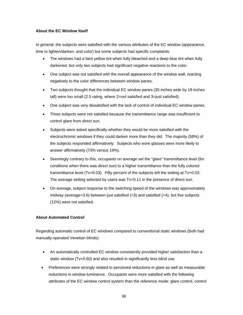
About the EC Window Itself
In general, the subjects were satisfied with the various attributes of the EC window (appearance,
time to lighten/darken, and color) but some subjects had specific complaints:
• The windows had a faint yellow tint when fully bleached and a deep blue tint when fully
darkened, but only two subjects had significant negative reactions to the color.
• One subject was not satisfied with the overall appearance of the window wall, reacting
negatively to the color differences between window panes.
• Two subjects thought that the individual EC window panes (35 inches wide by 18 inches
tall) were too small (2.5 rating, where 2=not satisfied and 3=just satisfied).
• One subject was very dissatisfied with the lack of control of individual EC window panes.
• Three subjects were not satisfied because the transmittance range was insufficient to
control glare from direct sun.
• Subjects were asked specifically whether they would be more satisfied with the
electrochromic windows if they could darken more than they did. The majority (58%) of
the subjects responded affirmatively. Subjects who wore glasses were more likely to
answer affirmatively (73% versus 19%).
• Seemingly contrary to this, occupants on average set the “glare” transmittance level (for
conditions when there was direct sun) to a higher transmittance than the fully colored
transmittance level (Tv=0.03). Fifty percent of the subjects left the setting at Tv=0.03.
The average setting selected by users was Tv=0.11 in the presence of direct sun.
• On average, subject response to the switching speed of the windows was approximately
midway (average=3.6) between just satisfied (=3) and satisfied (=4), but five subjects
(12%) were not satisfied.
About Automated Control
Regarding automatic control of EC windows compared to conventional static windows (both had
manually-operated Venetian blinds):
• An automatically controlled EC window consistently provided higher satisfaction than a
static window (Tv=0.60) and also resulted in significantly less blind use.
• Preferences were strongly related to perceived reductions in glare as well as measurable
reductions in window luminance. Occupants were more satisfied with the following
attributes of the EC window control system than the reference mode: glare control, control

37
of reflections on the computer monitor, and ability to control the windows and lighting
system.
• The interior Venetian blinds were used by 23% of the occupants with the automatically-
controlled EC window. With the static window, the blinds were used by 62% of the
occupants.
About Visual Comfort
With respect to visual comfort and lighting quality, the EC alone was insufficient to control window
glare, but the blinds were used less frequently (fully raised) with the dynamic EC modes than the
reference mode:
• Subjects rated their overall level of glare sensation as barely above perceptible (2.3 on
average, where 1=not perceptible, 2=perceptible, 3=acceptable, 4= uncomfortable, and
5=intolerable) for the automated EC window. For the reference static window, the glare
sensation was 2.7 on average. This difference was not statistically significant, indicating
that the subject (after having lowered the blind) was able to control glare adequately with
any of the three modes. The reference mode tended to have more light available from
the window than the automated EC window, even when the blinds were lowered.
• The Venetian blinds were used primarily to reduce glare from daylight or sunlight (57% of
responses) or to reduce the overall brightness of the room (33% of responses). The
blinds were used more often with the reference static window than with the automated
EC window. There was no significant difference in the way they were used, between the
different modes, once they were deployed. The tilt angle averaged 70±15º (view toward
the ground from interior). The average blind height for all modes was about half-way
lowered over the window (i.e. 5.5±3.3 (0=down, 10=up)). This is an average height
above the floor of 1.6 m, which allows a seated person a horizontal view out.
• The test room lighting level for the automatic mode was judged just right, 3.08 average
(where 3=just right and 5=too bright) while the reference mode was judged 3.46 on
average.
• On a scale of 1 to 5 with 1=unnatural and 5=natural, the room color rendering was judged
3.4 on average between all three modes. Only one of the 43 subjects felt that the room
color rendering was unnatural. The ceiling and walls were painted white. The carpet was
gray and the furniture was a warm gray with a slight purple hue.
38
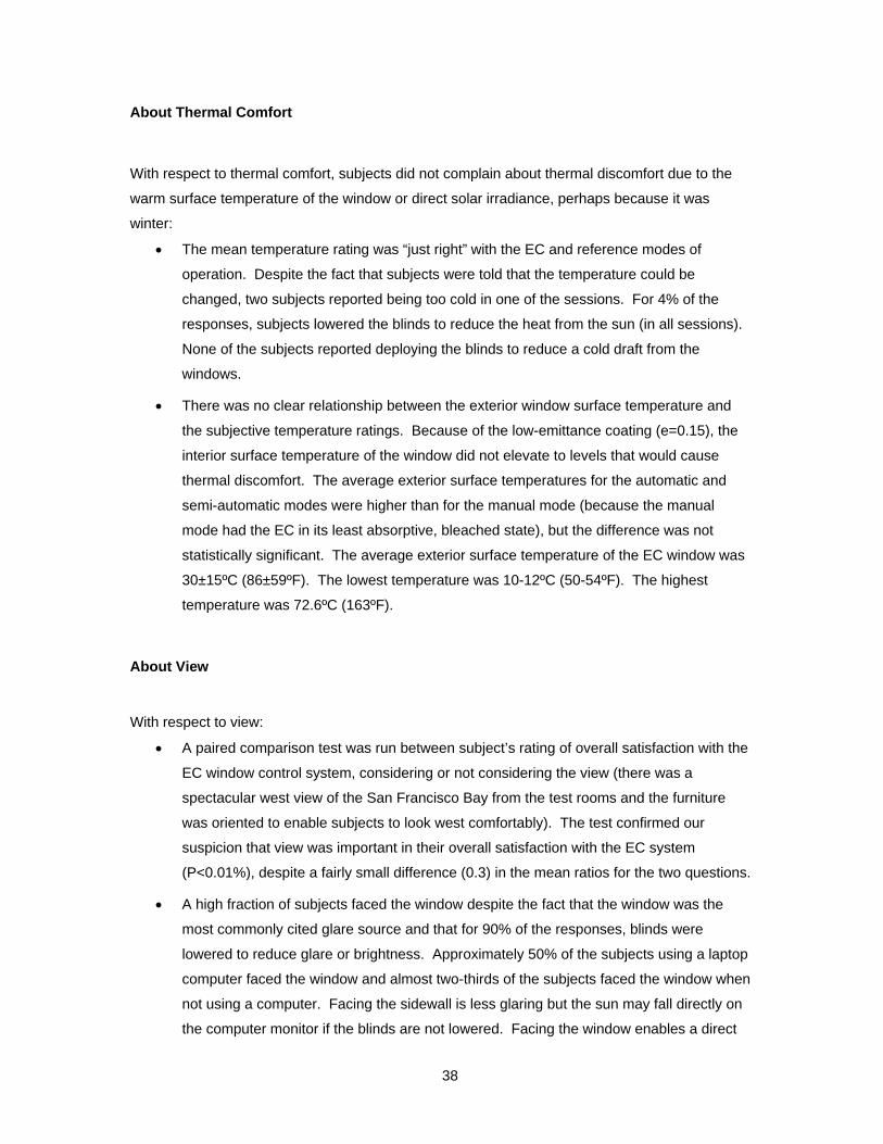
About Thermal Comfort
With respect to thermal comfort, subjects did not complain about thermal discomfort due to the
warm surface temperature of the window or direct solar irradiance, perhaps because it was
winter:
• The mean temperature rating was “just right” with the EC and reference modes of
operation. Despite the fact that subjects were told that the temperature could be
changed, two subjects reported being too cold in one of the sessions. For 4% of the
responses, subjects lowered the blinds to reduce the heat from the sun (in all sessions).
None of the subjects reported deploying the blinds to reduce a cold draft from the
windows.
• There was no clear relationship between the exterior window surface temperature and
the subjective temperature ratings. Because of the low-emittance coating (e=0.15), the
interior surface temperature of the window did not elevate to levels that would cause
thermal discomfort. The average exterior surface temperatures for the automatic and
semi-automatic modes were higher than for the manual mode (because the manual
mode had the EC in its least absorptive, bleached state), but the difference was not
statistically significant. The average exterior surface temperature of the EC window was
30±15ºC (86±59ºF). The lowest temperature was 10-12ºC (50-54ºF). The highest
temperature was 72.6ºC (163ºF).
About View
With respect to view:
• A paired comparison test was run between subject’s rating of overall satisfaction with the
EC window control system, considering or not considering the view (there was a
spectacular west view of the San Francisco Bay from the test rooms and the furniture
was oriented to enable subjects to look west comfortably). The test confirmed our
suspicion that view was important in their overall satisfaction with the EC system
(P<0.01%), despite a fairly small difference (0.3) in the mean ratios for the two questions.
• A high fraction of subjects faced the window despite the fact that the window was the
most commonly cited glare source and that for 90% of the responses, blinds were
lowered to reduce glare or brightness. Approximately 50% of the subjects using a laptop
computer faced the window and almost two-thirds of the subjects faced the window when
not using a computer. Facing the sidewall is less glaring but the sun may fall directly on
the computer monitor if the blinds are not lowered. Facing the window enables a direct

39
view out and prevents the sun from falling on the monitor while keeping reflections off the
monitor but creates contrast problems between VDT screen brightness and view
brightness.
• Foot traffic near the windows was minimal and none of the subjects reported deploying
the blinds for privacy. Blinds were deployed 4% to decrease the level of visual stimuli
from the outside.
40
Resources
Industry Contacts
At present, SAGE Electrochromics, Inc. is the only manufacturer selling electrochromic insulating
glasss units:
Mike Myser SAGE Electrochromics, Inc.
One Sage Way
Faribault, MN 55021
(507) 331-4903
http://www.sage-ec.com
SAGE sells IGUs to Velux for their switchable electrochromic skylight product line: electric venting
skylights, fixed skylights, and fixed curb-mounted skylights in various rectangular sizes.
http://www.veluxusa.com/
Other U.S. companies are also developing electrochromic window products but have not yet
come out with a commercial product:
Dr. Thomas Guarr
Gentex Corporation
600 N. Centennial Street
Zeeland, MI 49464
(616) 772-1590 ext. 434
Mr. Jay Wolfington
Eclipse Energy Systems, Inc.
2345 Anvis Street North
St. Petersburg, FL 33710
(727) 344-7300 x206

41
California Utility Contacts
California Utilities have emerging technology programs that assist building owners and
architectural/ engineering (A/E) teams to overcome the technical and cost hurdles of adopting a
new technology. The following contacts may be able to assist consumers located in their service
territory and point consumers to locations where the EC window can be viewed firsthand.
Bill Burke
Pacific Energy Center
851 Howard St.
San Francisco, CA 94103
(415) 973-9951
[email protected] (that's a zero after the 'b')
Connie Buchan
Sacramento Municipal Utility District
6301 S Street
P.O. Box 15830, MS-A226
Sacramento, CA 95852-1830
(916) 732-6404
Doug Avery
Southern California Edison
6042 N. Irwindale Avenue
Suite B
Irwindale, CA 91702
(626) 633-7182
A.Y. Ahmed
San Diego Gas & Electric
Southern California Gas
555 W. Fifth St, GT15E3
Los Angeles, CA 90013-1035
(213) 244-5308

42
R&D Organizations
Lawrence Berkeley National Laboratory Environmental Energy Technologies Division
Building Technologies Program
1 Cyclotron Road, MS-90-3111
Berkeley, CA 94720
Stephen Selkowitz, Building Technologies Program Head, [email protected]
Eleanor Lee, Building Performance, [email protected]
Tom Richardson, Reflective Hydrides, [email protected]
http://windows.lbl.gov/
National Renewable Energy Laboratory 1617 Cole Boulevard
Golden, CO 80401
Roland Pitts, Durability Testing, Electrochromic Materials, Degradation Mechanisms
http://www.nrel.gov/buildings/windows/durability.html
National Fenestration Rating Council Labeling Subcommittee: Dynamic Glazing Task Group
http://www.nfrc.org/
Switchable Facade Technology Project (completed 2003) (Headed by Fraunhofer Institute for Solar Energy Systems, Freiburg)
Project documentation and technical reports can be found at:
http://www.eu-swift.de/
An architectural guideline is also available at this site.
Technical Reports
The “Advancement of Electrochromic Windows” project, supported by the California Energy
Commission through its Public Interest Energy Research (PIER) Program and by the U.S.
Department of Energy, has produced the following technical reports:
43
Final Report
Lee, E.S., S.E. Selkowitz, R.D. Clear, D.L. DiBartolomeo, J.H. Klems, L.L. Fernandes, G.J.
Ward, V. Inkarojrit, M. Yazdanian. 2006. Advancement of Electrochromic Windows. California
Energy Commission, PIER. 500-01-023. LBNL-59821.
and the following appendices:
Systems Engineering
1. Lee, E.S., S.E. Selkowitz, M.S. Levi, S.L. Blanc, E. McConahey, M. McClintock, P.
Hakkarainen, N.L. Sbar, M.P. Myser. 2002. “Active Load Management with Advanced
Window Wall Systems: Research and Industry Perspectives”. Proceedings from the
ACEEE 2002 Summer Study on Energy Efficiency in Buildings: Teaming for Efficiency,
August 18-23, 2002, Asilomar, Pacific Grove, CA. Washington, D.C.: American Council
for an Energy-Efficient Economy. LBNL-50855, Lawrence Berkeley National Laboratory,
Berkeley, CA.
2. Lee, E.S., D.L. DiBartolomeo, F.M. Rubinstein, S.E. Selkowitz. 2004. Low-Cost
Networking for Dynamic Window Systems. Energy and Buildings 36(6):503-513. LBNL-
52198, Lawrence Berkeley National Laboratory, Berkeley, CA.
3. Tavil, A. and E.S. Lee. 2005. The impact of overhang design on the performance of the
electrochromic windows. Proceedings of the International Solar Energy Society (ISES)
Solar World Congress, Orlando, Florida on August 8-12, 2005. LBNL-57020.
4. Lee, E.S. and A. Tavil. 2005. An assessment of the visual comfort and energy
performance of electrochromic windows with overhangs. Submitted to Building and
Environment, October 14, 2005. LBNL-59064, Lawrence Berkeley National Laboratory,
Berkeley, CA.
5. Fernandes, L., G. Ward, E.S. Lee. 2005. Radiance-Mathematica optimization of
electrochromic operations for occupant comfort and non-energy provisions. Technical
report.

44
Performance Impacts Energy Use and Peak Demand Impacts 6. Lee, E.S., D. L. DiBartolomeo. 2002. Application issues for large-area electrochromic
windows in commercial buildings. Solar Energy Materials & Solar Cells 71 (2002) 465–
491. LBNL-45841, Lawrence Berkeley National Laboratory, Berkeley, CA.
7. Lee, E.S., D.L. DiBartolomeo, S.E. Selkowitz. 2005. Daylighting control performance of
a thin-film ceramic electrochromic window: Field study results. Energy and Buildings 38
(2006) 30-44. LBNL-54924, Lawrence Berkeley National Laboratory, Berkeley, CA.
8. Lee, E.S., D.L. DiBartolomeo, J. Klems, Ph.D., M. Yazdanian, S.E. Selkowitz. 2005.
Monitored Energy Performance of Electrochromic Windows Controlled for Daylight and
Visual Comfort. To be presented at the ASHRAE 2006 Annual Meeting, Quebec City,
Canada, June 24-28, 2006 and published in ASHRAE Transactions. LBNL-58912.
9. Lee, E.S., M. Yazdanian, S.E. Selkowitz. 2004. The Energy-Savings Potential of
Electrochromic Windows in the US Commercial Buildings Sector. LBNL-54966,
Lawrence Berkeley National Laboratory, Berkeley, CA.
10. Klems, J. 2004. Thermal calibration of the windows testbed facility. Technical report.
Occupant Impacts 11. Clear, R.D., V. Inkarojrit, E.S. Lee. 2005. Subject responses to electrochromic
windows. Submitted to Energy and Buildings, February 23, 2005. LBNL-57125,
Lawrence Berkeley National Laboratory, Berkeley, CA.
12. Inkarojrit, V. 2004. Analysis of visual comfort using high-dynamic-range luminance
images. Poster report. http://windows.lbl.gov/comm_perf/electroSys-cec.htm.
13. Clear, R.D. 2005. Assessment of visual comfort study in a full-scale electrochromic
window testbed. Technical report. http://windows.lbl.gov/comm_perf/electroSys-cec.htm.
Information Resources
14. Exerpt from: Carmody, J., S. Selkowitz, E.S. Lee, D. Arasteh, T. Wilmert. 2004.
Window Systems for High Performance Commercial Buildings. New York: W.W. Norton
and Company, Inc.
15. Lee, E.S., S. Selkowitz, V. Bazjanac, V. Inkarojrit, C. Kohler. 2002. High-Performance
Commercial Building Façades. LBNL-50502, Lawrence Berkeley National Laboratory,
Berkeley, CA.
45
16. Lee, E.S., S.E. Selkowitz, R.D. Clear, D.L. DiBartolomeo, J.H. Klems, L.L. Fernandes,
G.J. Ward, V. Inkarojrit, M. Yazdanian. 2006. A Design Guide for Early-Market
Electrochromic Windows. California Energy Commission, PIER. 500-01-023. LBNL-
59950.
17. Summary of Technology Transfer Activities: Journal articles, conference papers, popular
press, and presentations, including copies of articles.
Other LBNL technical reports on electrochromic windows are available at:
http://btech.lbl.gov/pub/papers.html
Search for title: electrochromics.
References
Granqvist, C.G. 2000. Electrochromic Tungsten Oxide Films: Review of Progress 1993-1998.
Solar Energy Materials & Solar Cells 60 (2000) 201-262.
Wienold, J. 2003. Switchable façade technology: Building integration – Final report. Report
number: swift-wp3-ise-jw-030616, Fraunhofer Institute for Solar Energy Systems, Heidenhofstr. 2,
D-79110 Freiburg. http://www.eu-swift.de/
Zinzi, M. 2006. “Office worker preferences of electrochromic windows: a pilot study”, Building and
Environment, in press, 2006.

46
Appendix: Curtainwall Details for an Electrochromic Window Wall
Attached are curtainwall details developed by Wausau Window and Wall Systems for the LBNL
Windows Test Facility.