Embed Size (px)
Citation preview

University of Nebraska - Lincoln University of Nebraska - Lincoln
DigitalCommons@University of Nebraska - Lincoln DigitalCommons@University of Nebraska - Lincoln
Faculty Publications in Computer & Electronics Engineering (to 2015)
Electrical & Computer Engineering, Department of
2011
A Cross-Layer Parallel Handover Optimization Scheme for WiMAX A Cross-Layer Parallel Handover Optimization Scheme for WiMAX
Networks Networks
Ting Zhou University of Nebraska-Lincoln, [email protected]
Hamid Sharif University of Nebraska-Lincoln, [email protected]
Michael Hempel University of Nebraska Lincoln, [email protected]
Puttipong Mahasukhon University of Nebraska-Lincoln, [email protected]
Tao Ma University of Nebraska Lincoln, [email protected]
See next page for additional authors
Follow this and additional works at: https://digitalcommons.unl.edu/computerelectronicfacpub
Part of the Computer Engineering Commons
Zhou, Ting; Sharif, Hamid; Hempel, Michael; Mahasukhon, Puttipong; Ma, Tao; and Shrestha, Pradhumna, "A Cross-Layer Parallel Handover Optimization Scheme for WiMAX Networks" (2011). Faculty Publications in Computer & Electronics Engineering (to 2015). 94. https://digitalcommons.unl.edu/computerelectronicfacpub/94
This Article is brought to you for free and open access by the Electrical & Computer Engineering, Department of at DigitalCommons@University of Nebraska - Lincoln. It has been accepted for inclusion in Faculty Publications in Computer & Electronics Engineering (to 2015) by an authorized administrator of DigitalCommons@University of Nebraska - Lincoln.

Authors Authors Ting Zhou, Hamid Sharif, Michael Hempel, Puttipong Mahasukhon, Tao Ma, and Pradhumna Shrestha
This article is available at DigitalCommons@University of Nebraska - Lincoln: https://digitalcommons.unl.edu/computerelectronicfacpub/94

BS BS
ASN-GW ASN-GW
R1 R1 R1
R8
R4
R6
R6
R3
BS BS
R1
R8
R6
R6
ASN ASN
R3
Intra-ASN (R8) Inter-ASN (R6-R4) Intra-ASN (R6)
A
A
DCB
CSN
Figure 1. WiMAX mobility scenario
A Cross-Layer Parallel Handover Optimization
Scheme for WiMAX Networks
Ting Zhou, Hamid Sharif, Michael Hempel, Puttipong Mahasukhon, Tao Ma, Pradhumna Lal Shrestha
Computer and Electronics Engineering Department
University of Nebraska-Lincoln
Omaha, NE USA
{tzhou, hsharif, mhempel, pmahasukhon, tma, plshrestha}@ unlnotes.unl.edu
Abstract— The handover performance plays a crucial role in
guaranteeing the quality of real-time applications in WiMAX
networks. In general, a handover process can be divided into
four stages: i) cell reselection, ii) handover preparation, iii) link
layer handover, and iv) IP layer handover. A cross-layer parallel
handover optimization (CPHO) scheme is proposed in this paper
to reduce the handover signaling overhead and latency in each
stage. The key idea of our proposed scheme is that uses the
knowledge achieved from the backhaul inter-BS communications
to reduce the HO control message load in wireless links and
overlaps the executions of the link layer and the network layer
handover process. Therefore the mean of the handover
interruption time can be significantly reduced. The numerical
analysis and simulation results show that the proposed approach
significantly enhances the handover performance.
Keywords- Handover, WiMAX, Cross-layer Optimization
I. INTRODUCTION
A full end-to-end WiMAX network is defined by IEEE
802.16 standards [1] and WiMAX Forum Network Working
Group (NWG) specifications [2]. The IEEE 802.16 standard
defines the air interface specifications, including the physical
(PHY) and medium access control (MAC) layers to support
high speed data transmission and mobility service. The whole
architecture reference model, reference points, protocols and
procedures of WiMAX networks are described in WiMAX
NWG specifications to ensure interoperability among different
equipment vendors. WiMAX has been approved by ITU-T as
a 3G standard since 2007, as well as UMTS and CDMA2000.
Sprint, the third largest wireless carrier in North America, has
launched WiMAX services in more than 30 major cities since
2009. Sprint’s peak download speed is up to 12Mbps and the
average downlink speed is about 2-4Mbps.
Handover is the process of maintaining the service
connection of a mobile station (MS) as it changes its point of
attachment (PoA) to the access network. There are two
categories of handover: the link layer (Layer-2) handover
(L2HO) and the network layer (Layer-3) handover (L3HO).
The L2HO only changes the physical access interface
attachment point of an MS, while a L3HO involves changes in
the IP configurations of the MS.
The architectural reference model of WiMAX networks,
defined by the NWG, can be logically divided into two parts:
Network Service Provider (NSP) and Network Access
Provider (NAP). The core component of NSP is the
Connectivity Service Network (CSN), which performs core
network functions such as policy and admission control, IP
address allocation, authentication and billing. It is also
responsible for internetworking with non-WiMAX networks
and for roaming through links to other NSPs. The NAP
provides a complete set of link layer connectivity functions to
WiMAX subscribers. It includes one or more Access Service
Networks (ASNs). An ASN is composed of at least one BS
and one gateway (ASN-GW). The WiMAX NWG Release 1
[6] defines three profiles that classify the distribution of
functions among BS and ASN-GW. Profile C is supported by
most device vendors, in which HO is controlled by the BS.
Also, the Radio Resource Controller (RRC) is located at the
BS, while the ASN-GW is equipped with an RRC relay for
delivering Radio Resource Management (RRM) messages
among BSs.
The NWG has developed several open-interface reference
points (RPs). R1 is the radio interface between BS and MS,
which is defined in the IEEE 802.16 standard. Other RPs,
from R2 to R8, are defined in NWG specifications. There are
three kinds of mobility scenarios in WiMAX networks (Fig-1).
R6/R4 HO is referred to as inter-ASN HO, while R6 and R8
Manuscript submitted at April 15th, 2011. This work was supported by a grant from the Federal Railroad Administration (FRA) under Grant 25-1105.
Support was provided to us by BNSF and Union Pacific Railroad.
The authors are with the Telecommunications Engineering Laboratory (TEL), Department of Computer and Electronics Engineering, University of
Nebraska-Lincoln, Omaha, NE 68182 USA (e-mail: [email protected]).
The 2011 Military Communications Conference - Track 2 - Network Protocols and Performance
978-1-4673-0081-0/11/$26.00 ©2011 IEEE 699
doi: 10.1109/MILCOM.2011.6127757
Cell Reselection L2HO L3HO
Cell
ReselectionL2HO
L3HO
By Backhaul
Communication
Existing
Scheme
Our Proposed
CPHO scheme
Figure 2. Key idea of our proposed CPHO scheme
HO belong to intra-ASN HO. Inter-ASN HO includes both
L2HO and L3HO, which involves the change of FAs.
In this paper, we focus on the optimization of the inter-ASN
mobility scenario. First we analyze the inter-ASN handover
process in WiMAX networks, and then propose our cross-
layer parallel handover optimization (CPHO) scheme, which
utilizes backhaul inter-BS communications and overlaps
L2HO and L3HO executions to reduce cell reselection and
handover execution latency. The key idea of CPHO is shown
in Fig. 2. By reducing handover interruption, the QoS of real-
time applications can be improved. Both theoretical analysis
and NS-2 simulations show that our proposed approach can
significantly enhance handover performance.
The remainder of this paper is structured as follows. In
Section II, a detailed analysis of the handover process in
WiMAX networks is provided and related research studies are
reviewed. The architecture of our proposed cross-layer
handover optimization approach is presented in Section III.
Theoretical analysis and simulation validation are presented in
Section IV and V respectively. Finally, Section VI concludes
the paper.
II. HANDOVER PROCESS ANALYSIS AND RELATED WORK
To provide mobility services, the IEEE 802.16 standard
specifies three different types of L2HO management
techniques: hard handover (HHO), which is mandatory,
macro-diversity handover (MDHO), and fast BS switching
(FBSS). The implementation of HHO is simplest, however in
which an MS suffers from service disruption until it completes
the network re-entry process with the target BS. This results in
usually a long interruption with negative impact on packet
loss, and degrades the quality of the time sensitive real-time
applications. In MDHO and FBSS, an MS can register with
several base stations (BS) simultaneously, as long as they
share the same carrier frequency and a common timing source.
They can achieve less handover latency at the expense of
network overhead, implementation complexity and limited
frequency reuse.
Two L3HO management types, Client Mobile IP (CMIP)
[3] and Proxy Mobile IP (PMIP) [4], are optionally supported
in WiMAX NWG. In the CMIP mechanism, an MS registers
on foreign networks and connects back to its home network
via a combination of Foreign Agents (FAs) and Home Agents
(HAs). When an MS moves to another network, it will detect
a new FA, obtain a Care-of-Address (CoA), and then register
this CoA with the HA. The CoA is used by the HA to tunnel
and forward packets to the MS directly. With PMIP, an MS
gets a new IP address by DHCP [5] when it moves to another
network. The HA does not forward packets directly to the MS,
but sends them to an FA in the visited network. The FA is
responsible for delivering packets to the MS. In CMIP, the
MIP stack exists in an MS, increasing complexity. Also, CMIP
is incompatible with IP-sec based virtual private networks
(VPNs) and network address translator (NAT) gateways. In
PMIP, it is not necessary to implement a client MIP stack in
MS, simplifying the MS implementation. However, because
PMIP is dependent on FAs to relay packets, it requires more
network overhead than CMIP. During L3HO, the MS must re-
register with HA and bind with FA, so it causes longer handoff
latency and higher packet loss than with L2HO. Fast Mobile
IPv6 (FMIPv6) [6] is designed by Internet Engineering Task
Force (IETF) to improve handover performance over Mobile
IPv6 in assistance with Layer-2 event triggers.
A handover may be initiated by either BSs or MSs. An MS
may initiate a handover when it detects that the received radio
signal from its serving BS deteriorates or experiences
interference in the current frequency band. A BS may initiate a
handover to balance an uneven distribution of MS traffic.
A HHO process in WiMAX networks can generally be
divided into four stages: i) cell reselection; ii) HO initiation
and preparation; iii) L2HO execution; and iv) L3HO
execution.
Cell reselection refers to the process of collecting the
information of candidate target BSs by scanning and/or
associating with one or more BSs to determine their
suitability. At the HO initiation and preparation stage, the MS
decides on triggering HO from the serving BS to the target BS
while the serving BS is responsible for releasing current
connections and resources.
A few existing 802.16 HO-enhanced schemes focus on the
optimization of the cell reselection stage to accurately predict
the HO target BS and reduce the number of scanned channels.
By measuring the human mobility patterns for two months, the
author in [7] found that the most popular destination pair is
home to work (office or school) and vice versa followed by
home to mall and work to food or pubs. Also, about 90% of
the time people choose the same route. The authors therefore
assumed that with previously acquired knowledge of human
mobility behavior, an MS can maintain a sequence of BS IDs
to which it connects while on a trip. This way, the target BSs
can be chosen before HO is sought.
Other existing HO-optimized schemes focus on either the
L2HO or L3HO process. A passport handover scheme was
proposed in [8] to accelerate the Layer-2 handover process. In
this scheme, the connection CIDs assigned by the serving BS
are accepted by the handover target BS during the handover
process until new CIDs are assigned by an REG-RSP message.
However, without inter-BS communications, to avoid old
CIDs, which are carried by the handover MS to collide with
existing CIDs in the target cell, the passport handover scheme
marks a certain reserved 3-bit-length in a 16-bit CID to satisfy
the traditional 1/7 frequency reuse strategy. [9] proposed a
mechanism that optimizes the FMIPv6 handover procedure
with the assistance of IEEE 802.21 [10] MIH services for
vehicular networking. The main improvements include
700

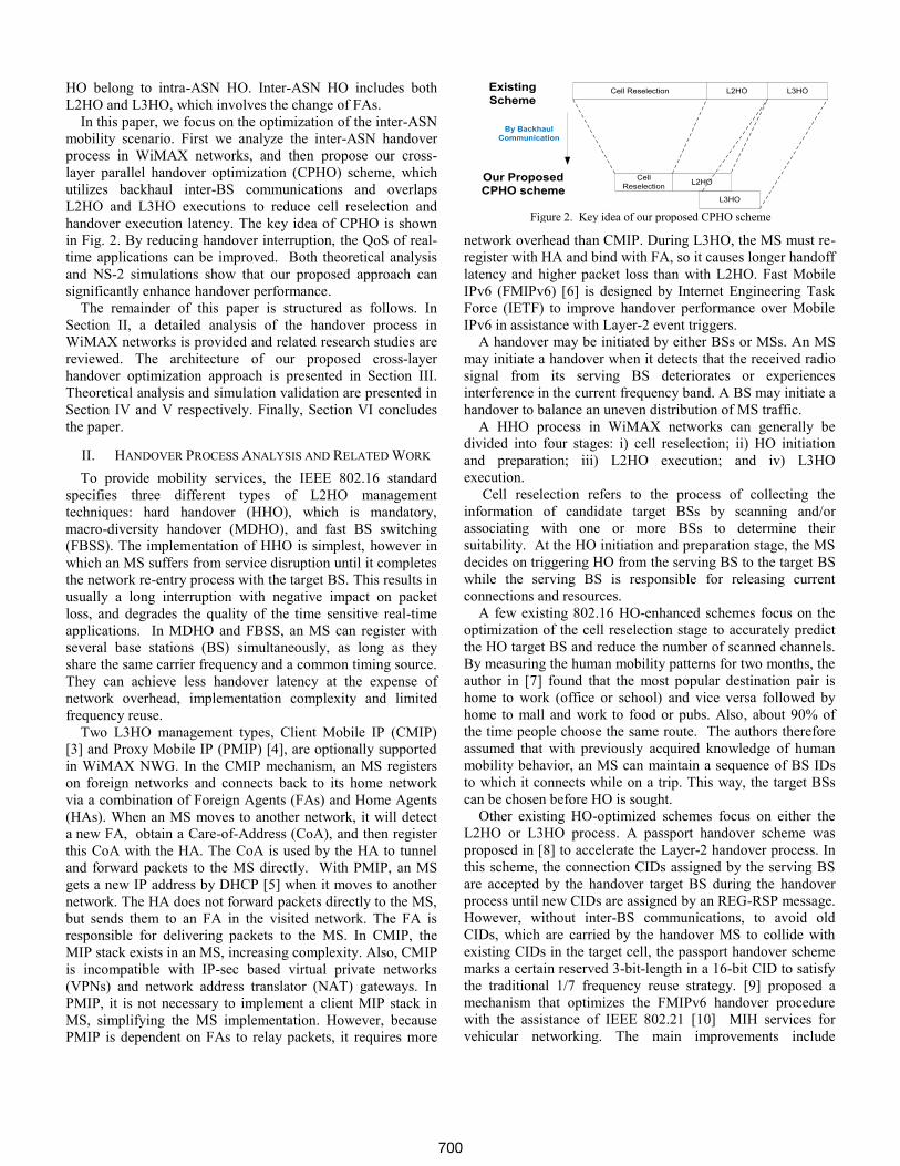
Figure 4. The relationship between scanning channel latency and association levels
0
8
16
0
10
200
500
1000
1500
2000
2500
Channel Num
Association Level 0
Frame Duration(ms)
Scannin
g C
hannel Late
ncy(m
s)
0
8
16
0
10
200
500
1000
1500
Channel Num
Association Level 1
Frame Duration(ms)
Scannin
g C
hannel Late
ncy(m
s)
0
8
16
0
10
20200
400
600
800
1000
Channel Num
Association Level 2
Frame Duration(ms)
Scannin
g C
hannel Late
ncy(m
s)
RNG-RSP
REG-REQ
REG-RSP
STA
Target BS
DSA-REQ (for DL)
DSA-REQ (for UL)
DSX-RVD (for DL)
DSA-RSP (for DL)
DSX-RVD (for UL)
DSA-RSP (for UL)
DSA-ACK (for UL)
RS
RA
redirect message
HA
ack for redirect packet
Serving BS
MSHO-REQ
MSHO-RSP
MSHO-ACK
RNG-REQ
DSA-ACK (for DL)
Serving ASN-GW Target ASN-GW
RNG-RSP
REG-RSP , DSA-RSP (for DL) ,DSA-RSP (for DL)
Target BS
RA
HA
ack for
redirect packet
Serving BS
MSHO-REQ
BSHO-RSP
MSHO-IND
RNG-REQ
DSA-ACK (for DL) and DSA (for UL)
Serving ASN-GW Target ASN-GW
Wireless Link
HO-REQ
HO-REQ
HO-REQ
HO-RSP
HO-RSP
HO-RSP
HO-ACK
HO-ACK
HO-ACK
redirect
message
ack for redirect packet (Buffered)
Backhaul Link
Without Backhaul Communication Proposed CPHO
L3 L2
Data
STA
L3 L2
Data
Figure 3. Message flow comparison between the existing scheme and our proposed CPHO scheme
broadcasting Layer-2 and Layer-3 neighboring access network
information together, and storing the latest received routing
messages in the cache of the MS to reduce signaling overheads
and the long anticipation time imposed by MIPv6.
To the best of our knowledge, our proposed CPHO scheme
is the first one that optimizes each stage’s performance in the
handover process by redistributing handover message load
from the wireless links to the wired backhaul links, as well as
using the backhaul inter-BS communications information to
overlap the L2HO and L3HO executions.
III. PROPOSED CROSS-LAYER PARALLEL HANDOVER
OPTIMIZATION SCHEME
The framework of the proposed CPHO scheme is described
in detail as follows:
1) The BSs periodically broadcast an MOB_NBR-ADV
message. According to this message, an MS can get the
neighbor BS list of its serving BS.
2) An MS will come into the cell selection stage when the
signal strength of its serving BS is reduced and is less than the
given threshold.
3) At the cell selection stage, Association Level 2 (Network
Assisted Association Reporting) is used to collect the
information of candidate target BSs. Before channel scanning,
the SS sends an MOB_SCN-REQ message to the serving BS,
which includes a list of the candidate target BSs. Then the
serving BS negotiates with each target BS via backhaul
networks to assign the MS a dedicated ranging region, and
transmits the result to the MS by an MOB_SCN-RSP message.
Because the ranging response is sent via the backhaul network,
the MS does not have to wait for the response from the target
BS after sending the RNG-REQ message and can switch to the
next channel immediately. The serving BS aggregates all
ranging-related information into a single MOB_ASC-
REPORT message, and then forwards it to the MS.
4) In accordance with the information collected from the cell
selection stage, an HO decision is made for the MS to switch
from the serving BS to the HO target BS.
5) The MS notifies the serving BS about its decision to
perform an HO by issuing an MOB_MSHO-REQ message,
which includes the ID of the HO target BS and the QoS
requirement to the serving BS. The serving BS sends an HO-
REQ through the backhaul network via R4 and R6 paths to the
target BS. The target BS responds by sending an HO-RSP
message to the serving BS, which assigns the MS a dedicated
ranging region, including the downlink (DL) and the uplink
(UL) synchronization parameters such as ranging status,
timing offset adjustment, power level adjustment and
frequency offset adjustment. The serving BS encapsulates the
above information into an MOB_BSHO-RSP message, and
then forwards it to the MS. The MOB_HO-IND message, sent
by the MS, integrates link layer requests, including REG-REQ
and DSA-REQs for DL/UL in both directions and IP layer
requests which include the Router Solicitation (RS) and the
redirect message together. When receiving this MOB_HO-
IND message, the serving BS encapsulates its payload into a
HO-ACK message and sends it to the HO target BS. Through
the above inter-BS communications through the backhaul
network, the MS achieves the physical layer and MAC layer
synchronization parameters of the target BS before the L2HO
execution.
6) The HO target BS relays the redirect message to the HA,
and then stores the redirect acknowledgement, which is sent
by the HA into its cache.
7) The MS switches to the frequency of the HO target BS, and
then uses the dedicated UL time slot to send the RNG-REQ
message and wait for the RNG-RSP. The HO target BS sends
701
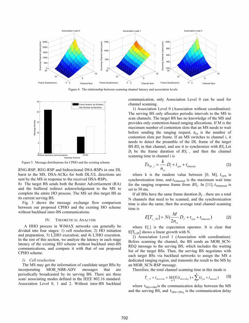
Figure 5. Message distributions for CPHO and the existing scheme
Without backhaul communications CPHO0
5
10
15
20
25
Handover Scheme
Message N
um
ber
Frame duration via Wireless
Hop Number via Backhaul
Figure 4. The relationship between scanning channel latency and association levels
0
8
16
0
10
200
500
1000
1500
2000
2500
Channel Num
Association Level 0
Frame Duration(ms)
Scannin
g C
hannel Late
ncy(m
s)
0
8
16
0
10
200
500
1000
1500
Channel Num
Association Level 1
Frame Duration(ms)
Scannin
g C
hannel Late
ncy(m
s)
0
8
16
0
10
20200
400
600
800
1000
Channel Num
Association Level 2
Frame Duration(ms)
Scannin
g C
hannel Late
ncy(m
s)
RNG-RSP, REG-RSP and bidirectional DSA-RSPs in one DL
burst to the MS. DSA-ACKs for both DL/UL directions are
sent by the MS in response to the received DSA-RSPs.
8) The target BS sends both the Router Advertisement (RA)
and the buffered redirect acknowledgement to the MS to
complete the entire HO process. The MS set this target BS as
its current serving BS.
Fig. 3 shows the message exchange flow comparison
between our proposed CPHO and the existing HO scheme
without backhaul inter-BS communications.
IV. THEORETICAL ANALYSIS
A HHO process in WiMAX networks can generally be divided into four stages: 1) cell reselection; 2) HO initiation and preparation; 3) L2HO execution; and 4) L3HO execution. In the rest of this section, we analyze the latency in each stage latency of the existing HO scheme without backhaul inter-BS communications, and compare it with that of our proposed CPHO scheme.
1) Cell reselection
The MS may get the information of candidate target BSs by
incorporating MOB_NBR-ADV messages that are
periodically broadcasted by its serving BS. There are three
scan/ associating modes defined in the IEEE 802.16 standard:
Association Level 0, 1 and 2. Without inter-BS backhaul
communication, only Association Level 0 can be used for
channel scanning.
1) Association Level 0 (Association without coordination):
The serving BS only allocates periodic intervals to the MS to
scan channels. The target BS has no knowledge of the MS and
provides only contention-based ranging allocations. If M is the
maximum number of contention slots that an MS needs to wait
before sending the ranging request, is the number of
contention slots per frame. If an MS switches to channel i, it
needs to detect the preamble of the DL frame of the target
BS in that channel, and use it to synchronize with .Let
be the frame duration of , and then the channel
scanning time in channel i is
0_l i i syn timeout
cs
kTs D t t
n (1)
where k is the random value between [0, M], is
synchronization time, and is the maximum wait time
for the ranging response frame from . In [11], is
set to 50 ms.
If all BSs have the same frame duration , there are a total
N channels that need to be scanned, and the synchronization
time is also the same, then the average total channel scanning
time is
_ 0[ ] ( )2
s l f syn timeout
cs
ME T N D t t
n (2)
where E[.] is the expectation operator. It is clear that
shows a linear growth with N.
2) Association Level 1 (Association with coordination):
Before scanning the channel, the BS sends an MOB_SCN-
REQ message to the serving BS, which includes the waiting
list of the target BSs. Then, the serving BS negotiates with
each target BSs via backhaul networks to assign the MS a
dedicated ranging region, and transmits the result to the MS by
an MOB_SCN-RSP message.
Therefore, the total channel scanning time in this mode is
_ 1 ( ) ( )i
N
s l ms sbs sbs tbs syn timeouti N
i
T t MAX t t t
(3)
where is the communication delay between the MS
and the serving BS, and is the communication delay
702
between the MS and the serving BS between the MS and the
target .
3) Association Level 2 (Network Assisted Association
Reporting): the procedure is similar to Level 1 except that the
MS does not wait for a response from the target BS. The
ranging response is sent by the target BS to the serving BS via
the backhaul network. The serving BS aggregates all ranging-
related information into a single MOB_ASC-REPORT
message, and then forwards it to the MS.
The total channel scanning time in this mode is
_ 2 ( )
( ) ( )
i
i
s l syn ms sbs sbs tbsi N
N
syn i tbs sbs sbs msi N
i
T t t MAX t
t D MAX t t
(4)
where is the MOB_ASC-REPORT message
transmit time, and is the time that each target
sends the ranging response to the serving BS.
Assuming that all BSs have the same frame duration Df,
, , and the
maximum backhaul communication delay is 100ms, the
scanning channel latency comparison among three association
levels is shown in Fig. 4. It is clear that using backhaul
communications, Association Level 2 has the lowest scanning
channel latency. If we cannot change the frame duration, a
reduction in the total number of scanning channels will
efficiently reduce the scanning channel latency. In the
proposed CPHO scheme, Association Level 2 is chosen for
channel scanning.
2) HO initiation and preparation
Based on the information collected from the cell selection
stage, the MS chooses the most suitable candidate BS as its
HO target BS.
In the existing scheme without integrating with the backhaul
inter-BS communications, the MS only notifies the serving BS
for releasing current connections and resources by exchanging
Mobile Scan Request (MOB_MSHO-REQ) and Mobile Scan
Response (MOB_SCN-RSP). The MS then transmits MOB
HO-IND to notify the serving BS to commence the HO
execution. Therefore, for the existing scheme, the
latency in this stage is
, 2p existing ms sbs sbs msT t t (5)
In the proposed CPHO scheme, the MS use the three-way
handshake to communicate with the target BS via the backhaul
links, and thus the latency is
, 2 2p CHPO ms sbs sbs ms sbs tbs tbs sbsT t t t t (6)
3) L2HO execution
In the existing scheme without backhaul communications,
after the MS switches to the frequency of the target BS and
discovers the initial ranging slot by the receiving ULMAP to
initiate the process of ranging, the MS has to pipeline execute
an RNG-REQ/RSP exchange, an REG-REQ/RSP exchange,
and two 4-way DSA handshakes. Given , the
latency in L2HO stage is
2, 6 6L existing f syn ms tbs tbs ms
cs
kT D t t t
n (7)
where k is the random value between [0, M].
However in the proposed CPHO scheme, the MS has
required the dedicated ranging slot and has sent REG-REQ
and DSA-REQs to the target BS via the backhaul links in the
previous stage, and so the REG-RSP and DSA-RSPs can be
transmitted together in one DL burst. Therefore the latency
can be reduced to
2 , 2 2L A CPHO ms tbs tbs msT t t (8)
Meanwhile the target BS relays the redirect message to the
MS’s HA and waits for the redirect acknowledgement from
the HA. The latency is
2 ,L B CPHO tbs HA HA tbsT t t (9)
The total CPHO latency in this stage is
2, 2 , 2 ,( , )L CPHO L A CPHO L B CPHOT MAX T T (10)
4) L3HO execution
In this stage, the existing scheme has to pipeline execute an
RS/RA handshake between the MS and the target BS, and a
redirect message handshake between the MS and the HA.
Thus the latency is
3, 2 2L existing ms tbs tbs ms tbs HA HA tbsT t t t t (11)
where and are the unidirectional delay from
the target BS to the HA or vice versa.
In this stage, the proposed CPHO scheme only needs to
transmit two downlink direction packets, which can be
transmitted together, and so the latency in this stage is
3,L CPHO tbs msT t (12)
Assuming , , and the
mobility scenario is the same as with Fig. 1. The transmit
frame duration number via the wireless links and the transmit
hop number via the wired links comparison between the
existing scheme and the proposed CPHO are shown in Fig. 5.
V. SIMULATION VALIDATION
The proposed CPHO scheme has been implemented in the
NS-2 network simulator [12] based on the National Institute of
Standards and Technology (NIST) WiMAX module [13]. To
simplify the scenario, every BS supports FA and access router
functions, in which one BS presents a different subnet. The
bidirectional VoIP traffic is established between HA and MS.
TABLE-1. SIMULATION PARAMETERS
Cell Layout (hexagonal cell) 7
Number of BS 10
Number of ASN-GW 2
Number of MS 1
802.16 Bandwidth (MHz) 10
802.16 FFT Size 1024
802.16 Frame Duration (msec) 10
802.16 Synchronization Delay (msec) 10
802.16 Ranging Timeout (msec) 50
802.16 Maximum Contention Window 5
MS Speed (m/s) 5
Wired Per-hop Delay (msec) 5
Hop Number between BS and HA 2
VoIP Packet Size (msec) 160
VoIP Traffic Rate (kbps) 400
703
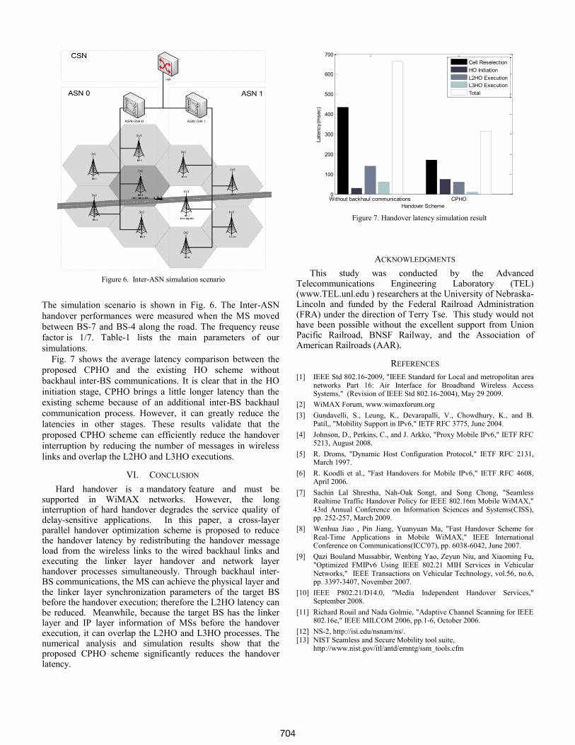
Figure 7. Handover latency simulation result
Without backhaul communications CPHO0
100
200
300
400
500
600
700
Handover Scheme
Late
ncy(m
sec)
Cell Reselection
HO Initiation
L2HO Execution
L3HO Execution
Total
Figure 6. Inter-ASN simulation scenario
The simulation scenario is shown in Fig. 6. The Inter-ASN
handover performances were measured when the MS moved
between BS-7 and BS-4 along the road. The frequency reuse
factor is 1/7. Table-1 lists the main parameters of our
simulations.
Fig. 7 shows the average latency comparison between the
proposed CPHO and the existing HO scheme without
backhaul inter-BS communications. It is clear that in the HO
initiation stage, CPHO brings a little longer latency than the
existing scheme because of an additional inter-BS backhaul
communication process. However, it can greatly reduce the
latencies in other stages. These results validate that the
proposed CPHO scheme can efficiently reduce the handover
interruption by reducing the number of messages in wireless
links and overlap the L2HO and L3HO executions.
VI. CONCLUSION
Hard handover is a mandatory feature and must be supported in WiMAX networks. However, the long interruption of hard handover degrades the service quality of delay-sensitive applications. In this paper, a cross-layer parallel handover optimization scheme is proposed to reduce the handover latency by redistributing the handover message load from the wireless links to the wired backhaul links and executing the linker layer handover and network layer handover processes simultaneously. Through backhaul inter-BS communications, the MS can achieve the physical layer and the linker layer synchronization parameters of the target BS before the handover execution; therefore the L2HO latency can be reduced. Meanwhile, because the target BS has the linker layer and IP layer information of MSs before the handover execution, it can overlap the L2HO and L3HO processes. The numerical analysis and simulation results show that the proposed CPHO scheme significantly reduces the handover latency.
ACKNOWLEDGMENTS
This study was conducted by the Advanced Telecommunications Engineering Laboratory (TEL) (www.TEL.unl.edu ) researchers at the University of Nebraska-Lincoln and funded by the Federal Railroad Administration (FRA) under the direction of Terry Tse. This study would not have been possible without the excellent support from Union Pacific Railroad, BNSF Railway, and the Association of American Railroads (AAR).
REFERENCES
[1] IEEE Std 802.16-2009, "IEEE Standard for Local and metropolitan area networks Part 16: Air Interface for Broadband Wireless Access Systems," (Revision of IEEE Std 802.16-2004), May 29 2009.
[2] WiMAX Forum, www.wimaxforum.org
[3] Gundavelli, S., Leung, K., Devarapalli, V., Chowdhury, K., and B. Patil,, "Mobility Support in IPv6," IETF RFC 3775, June 2004.
[4] Johnson, D., Perkins, C., and J. Arkko, "Proxy Mobile IPv6," IETF RFC 5213, August 2008.
[5] R. Droms, "Dynamic Host Configuration Protocol," IETF RFC 2131, March 1997.
[6] R. Koodli et al., "Fast Handovers for Mobile IPv6," IETF RFC 4608, April 2006.
[7] Sachin Lal Shrestha, Nah-Oak Songt, and Song Chong, "Seamless Realtime Traffic Handover Policy for IEEE 802.16m Mobile WiMAX," 43rd Annual Conference on Information Sciences and Systems(CISS), pp. 252-257, March 2009.
[8] Wenhua Jiao , Pin Jiang, Yuanyuan Ma, "Fast Handover Scheme for Real-Time Applications in Mobile WiMAX," IEEE International Conference on Communications(ICC'07), pp. 6038-6042, June 2007.
[9] Qazi Bouland Mussabbir, Wenbing Yao, Zeyun Niu, and Xiaoming Fu, "Optimized FMIPv6 Using IEEE 802.21 MIH Services in Vehicular Networks," IEEE Transactions on Vehicular Technology, vol.56, no.6, pp. 3397-3407, November 2007.
[10] IEEE P802.21/D14.0, "Media Independent Handover Services," September 2008.
[11] Richard Rouil and Nada Golmie, "Adaptive Channel Scanning for IEEE 802.16e," IEEE MILCOM 2006, pp.1-6, October 2006.
[12] NS-2, http://isi.edu/nsnam/ns/. [13] NIST Seamless and Secure Mobility tool suite,
http://www.nist.gov/itl/antd/emntg/ssm_tools.cfm
704


![Enabling Soft Vertical Handover for MIPv6 in OMNeT++address (layer 3 HO) is mobile IP in its two versions 4 and 6 [1], [2]. Fig. 1. Vertical Handover In this work, we give an insight](https://img.dokumen.tips/doc/110x75/5f47bd30eb1fe96e31603b07/enabling-soft-vertical-handover-for-mipv6-in-omnet-address-layer-3-ho-is-mobile.jpg)


![Mobility Management for Low-Latency Handover in SDN …lhyen/files/papers/1570220820.pdfsupport vertical handover and application layer session continuity [11] for service continuity](https://img.dokumen.tips/doc/110x75/5b2830287f8b9a0a708b5412/mobility-management-for-low-latency-handover-in-sdn-lhyenfilespapers1570220820pdfsupport.jpg)