Embed Size (px)
Citation preview

A CRASHWORTHINESS SIMULATION FOR A LIGHT AIRCRAFT CONSTRUCTED OFCOMPOSITE MATERIALS
Pu-Woei Chen and Kuan-Jung ChenDepartment of Aerospace Engineering, Tamkang University, Taiwan, R.O.C.
E-mail: [email protected]
Received July 2014, Accepted May 2015No. 14-CSME-80, E.I.C. Accession 3741
ABSTRACTThis study analyzes the crashworthiness of a light aircraft that is constructed from composite materials.The finite element method is employed to conduct dynamic impact simulations on carbon fiber compositefuselages. The results show that the safe impact speed for an aluminum alloy cockpit crashed at a 30◦ impactangle is 9.59 m/s, but a cockpit made of composite material can withstand a speed greater than 18.05 m/s.The safe impact angle for an aluminum alloy cockpit is 16.56◦, but that for a composite cockpit is 84.9◦.The safety crash zone for a composite material cockpit is 160% greater than that for an aluminum alloycockpit.
Keywords: light aircraft; crashworthiness; composite material; finite element method.
SIMULATION DE LA RÉSISTANCE AU CHOC D’UN AÉRONEF DE FAIBLE TONNAGECONSTRUIT DE MATÉRIELS COMPOSITES
RÉSUMÉLa résistance au choc d’un aéronef de faible tonnage construit de matériels composites est l’objet de notreétude. La méthode des éléments finis est employée pour la conduite des simulations de chocs dynamiquessur un fuselage fait de composite de fibre de carbone. Les résultats indiquent que la vitesse sécuritaire d’unangle d’impact pour un cockpit fait d’alliage d’aluminium qui s’est écrasé à un angle d’impact de 30◦ estde 9,59 m/s, mais un cockpit construit de matériels composites peut résister à une vitesse aussi élevée que18,05 m/s. L’angle de choc sécuritaire pour un cockpit fait d’alliage d’aluminium est de 16,56◦, tandis quecelui fait de matériels composites est de 84,9◦. La zone sécuritaire d’écrasement pour un cockpit construitde matériels composites est de 160% plus élevée que celle d’un cockpit en alliage d’aluminium.
Mots-clés : aéronef à faible tonnage; résistance au choc; matériel composite; méthode des éléments finis.
Transactions of the Canadian Society for Mechanical Engineering, Vol. 39, No. 4, 2015 829
1. INTRODUCTION
The safety of an aircraft depends on numerous factors, including its design and operation and adherenceto maintenance schedules. Guaranteeing the safety of airline occupants during aircraft accidents is vital.Recently, small aircraft have become more commonly used for short-distance transportation. In addition,light aircraft (LA) are commonly used for leisure purposes. Therefore, the safety of LA has attracted muchattention. Over the past few decades, composite materials have been frequently used in the primary andsecondary structures of large aircraft. In addition, fuselages that are completely constructed using compositematerials are a developing trend in both general aviation (GA) and LA. Because of the increasing use ofcomposite materials in aircraft manufacturing, determining the structural safety of composite materials infuselages is important.
The definition of GA differs between countries and laws. For example, the International Civil AviationOrganization defines GA as “an aircraft operation other than a commercial air transport operation or an aerialwork operation”. The Federal Aviation Administration (FAA) defines GA as “that portion of civil aviationwhich encompasses all facets of aviation except air carriers”. Based on these definitions, the definitionfor GA provided by the FAA encompasses a wide range of aircrafts. The General Aviation ManufacturerAssociation (GAMA) defined GA as “all aviation other than scheduled commercial airlines and militaryaviation”. Therefore, GA can be used to describe ultra-light aircraft, LA, Light Sport Aircraft (LSA), andexperimental airplanes that are installed with single, double, reciprocating, turboprop, and turbojet engines(e.g., small commercial airliners).
In the United States, GA manufacturing reached a peak in 1978, when 14,398 planes were manufac-tured and delivered. However, the aircraft industry then began to decline and only 444 aircraft were or-dered during 1994 [1]. The aircraft manufactured during this period are mostly more than 30 years old andwere produced using techniques from the 1950s. Therefore, the National Aeronautics and Space Admin-istration (NASA) have cooperated with various organizations to progressively initiate numerous programsthat promote the development of GA aircraft. From 1994 to 2001, the main purpose of the AdvancedGeneral Aviation Transport Experiments (AGATE) consortium was to develop composite material man-ufacturing technologies for small aircraft [2], to increase aircraft safety and crashworthiness, to improvethe efficiency of innovative engine, and to develop flight and control systems that correspond with mod-ern technologies. The AGATE consortium incorporated the General Aviation Propulsion program (whichresearches and develops innovative low-noise and high-efficiency engines) and the subsequent Small Air-craft Transportation System (SATS) program [3]. Since the initiation of SATS, in 2005, the primarygoal has been to promote air transport as an efficient alternative to ground transportation, in order to re-duce traffic congestion. SATS operations involve using small airports in the United States to provide GAaircraft or LA with a point-to-point flight-mode transportation model, thereby facilitating fast and easytravel.
GA is a vital part of the U.S. civil aviation transportation industry. For example, according to the statisticsof the National Transportation Safety Board (NTSB) [4], in 2005, 91% of civil aircraft (i.e., 215,837 aircraft)operating in the United States are GA aircraft. Of these GA aircraft, 211,940 continue to function and78% of small aircraft have single reciprocating engines. The European Personal Air Transportation Systemestimates that the number of small aircraft flights will be approximately 50,000,000 by 2020. Accordingly,the demand for small aircraft in Europe will be approximately 150,000–180,000. Based on these data, thedemand for GA is increasing in the global aircraft market. However, safety issues remain the primary factorsthat hinder the rapid development of GA. According to the statistical data of the Aviation Security AdvisoryCommittee, in 2003, the GA accident rate for every 100,000 flight hours was 10–35 times that for regularcommercial air transport [5] and the mortality rate for GA was 2.5–3 times that for commercial air transport.In 2007, the Air Safety Foundation of the Aircraft Owners and Pilot Association stated that 70% of fatal GA
830 Transactions of the Canadian Society for Mechanical Engineering, Vol. 39, No. 4, 2015

accidents were caused by personal pilots [6]. An NTSB report [4] indicated that 88% of GA accidents werecaused by aircraft with single reciprocating engines.
Composite materials are commonly used as the primary structural material for the fuselages of large air-craft, such as the Boeing 787, where 50% of the structural components are composite materials, and theAirbus A380, in which composite materials account for 25% of the aircraft’s weight. Composite materialsare also used in GA aircraft manufacturing. For example, of the 2,675 aircraft with single reciprocatingengines that were manufactured in 2007, 1,376 aircraft used composite materials, which was 51.4% of thetotal production volume [7]. This reflects a substantial increase since 10 years ago, when less than 5% ofsingle reciprocating engine aircraft were manufactured using composite materials. Currently, most compos-ite material used in LA is glass fiber, which is extensively used in various aircraft structures. Carbon fiber(CF) is also widely used in LA, such as the two-seat WT9 Dynamic, designed by Aerospool s.r.o. (SlovakRepublic). The WT9 Dynamic was certified as an ultra-light aircraft in Europe, in 2001. The fuselage of theWT9 Dynamic is constructed of composite material that comprises multi-layered CF-reinforced resin andaramid fiber skin layers. This is used in the cabin interior to increase the aircraft’s crashworthiness. Theprimary structural components of this aircraft use CF composites, but the airfoil skin and vertical stabilizeruse a sandwich structure that contains a mixture of glass fiber and CF. The main reason to use compos-ite materials in LA is to reduce aircraft weight and fuel consumption. The average fuel consumption ofa LA is approximately 4.5 gph (gallons per hour). For 5- or 6-seat small commercial airplanes with twinengines (e.g., the Cessna Turbo 310-R), the average fuel consumption is 24 gph. Consequently, most LAmanufacturers consider composite materials to be a vital design component in innovative aircraft models.
Current standards for aircraft design and structural strength are typically based on previous research intometallic materials and aviation-related experience. However, compared with the number of studies of metal-lic materials, there have been few studies of composite materials and the various synthetic fibers that arenow available. Therefore, few reliable simulation and empirical results are available for designers of air-craft structures. Specifically, there have been few studies of the attributes of composite material, such as itsfatigue properties, its strength retrogression because of long-term exposure to environmental factors and itsenergy absorption capabilities during a crash.
2. REVIEW OF THE LITERATURE
Although aviation safety management systems are rigorous, accidents caused by various factors are in-evitable. Well-designed aircraft can reduce the number of fatal injuries in an aircraft crash. Crashworthinessrefers to the capability of the overall aircraft system to protect occupants from fatal injuries in an aircraftaccident and the capability of the aircraft structure to ensure that there is sufficient space around the occu-pants, which increases the chance of survival in an aircraft crash. The primary cause of casualties in aircraftaccidents is a reduction in cockpit space, which is caused by the force of impact when the aircraft hitsthe ground. The U.S. Army established the MIL-STD-1290A [8] standard to assess aircraft crashworthi-ness. The capability of structures to absorb impact was considered when the standard was established (i.e.,to ensure occupant safety, the cabin compression value cannot exceed 15% when the aircraft experienceslongitudinal, vertical and lateral impacts).
A NTSB report states that between 1971 and 1982, 25% of all GA accidents caused deaths or major in-juries, so the NTSB examined GA crashworthiness from 1981 to 1985 [9], to determine the peak accelerationloads (g) that occupants can bear when an aircraft crashes at a 30◦ angle of depression. The NTSB assertedthat to increase occupant survival rates, seats should be reinforced and the restraint system improved. In1984, the FAA founded the General Aviation Safety Panel, whose primary research direction has been thetolerance of aircraft seats and seat belts to the forces experienced in survivable crashes [10]. From 1967 to1972, the U.S. Army investigated numerous rotorcraft crashes and claimed that if crash prevention had been
Transactions of the Canadian Society for Mechanical Engineering, Vol. 39, No. 4, 2015 831

considered in the preliminary aircraft design stage, 92.8% of these crashes would have been completely orpartially survivable. In 1989, the U.S. military published five reports, named the Aircraft Crash Survival De-sign Guide [11], which primarily discussed the crashworthiness design of military helicopters. This designguide was practically applied to two U.S. helicopter models: the UH-60 and the AH-64. The design guidealso noted that when aircraft crashworthiness is considered at the design stage, occupant survival rates areincreased in various crash conditions.
The NASA AGATE consortium also successively published results from studies of aircraft crashwor-thiness. Their study dealt with issues such as the development and verification of the conceptualiza-tion and design for the crashworthiness of regional aircraft and aircraft constructed of composite mate-rials [12]. The results demonstrate that designs which increase the crashworthiness of small airplanesare different to those required for larger airplanes, because the floors, sub-floors and bulkhead struc-tures of the fuselages of large aircraft are the structures that bear the initial impact force when crashesoccur. However, in small airplanes, the energy absorption systems that absorb the vertical impact andprotect the occupants are the undercarriage, fuselage, floor and seats. In addition to the energy ab-sorption mechanisms, excessive force that compresses the occupants’ cabin space is an essential factorin aircraft crashworthiness design. The target of the AGATE study were single-engine 2–6-seat aircraftthat are constructed using only composite materials and which weigh a maximum of 6,000 lb. Accord-ing to the military standard, MIL-STD-1290A, for aircraft with a vertical impact velocity of 12.80 m/s,the cockpit volume reducing rate must be lower than 15% to allow occupant survival. The aircraftcrash data collected by the AGATE study shows that aircraft crashing at an average impact velocityof 71 kts (36.52 m/s) and at a 31◦ nose down angle is the boundary condition or survivable accidentcriteria that potentially causes at least one occupant to survive and at least one occupant to be fatallyinjured.
Current studies of aircraft crashworthiness typically conduct vertical crash experiments on transport cat-egory aircraft or commuter aircraft [13–15], rather than LA, which have a maximum takeoff weight of lessthan 600 kg or 750 kg, for the FAA and European Aviation Safety Agency (EASA), respectively. Currentstandards for the U.S. LSA are found in ASTM 2245-13b [16]. Although this regulation provides a con-sistent standard for LA certification, the structural criteria are based exclusively on strength. In addition,the aircraft crashworthiness standards of the FAR exclusively address seats and restraint systems but haveno clearly specified design criteria for aircraft crashworthiness. The design standards for various types ofLA in Canada are relatively comprehensive [17], but aircraft crashworthiness is also insufficient. However,the Transportation Safety Board of Canada findings concerning the crashworthiness of small aircraft withtakeoff weights of less than 5,700 kg show that post-impact fires are a primary cause of casualties [18]. TheTransportation Safety Board also found that the three main influencing factors in survivable accidents are theimpact energy, the space within the airframe structure and the occupant restraint system. According to CS-VLA 561 [19], airplane structures must correspond to load requirements to provide occupants with escapeopportunities in emergency landing conditions. According to this provision, engine mounts must withstand15 g of weight. The European Vehicle Passive Safety Network II [20] of the European Union proposed theconcept of Total Aircraft Crashworthiness and Societal Safety (TACASS) to reduce occupant mortality dur-ing aircraft crashes. According to TACASS, to guarantee occupant safety during accidents, three principlesare vital: (1) crashworthiness must be considered during aircraft design to reduce the impact on occupantsduring crashes; (2) new structural technologies must be developed to reduce occupant injuries by improvingairframe deformation and energy absorption and (3) there must be sufficient space in airframe structures toallow occupants to survive and escape.
Aircraft crashworthiness is improved by improving aircraft structure and the material used for construc-tion. The NASA AGATE developed fuselages that are constructed of composite materials to increase aircraft
832 Transactions of the Canadian Society for Mechanical Engineering, Vol. 39, No. 4, 2015
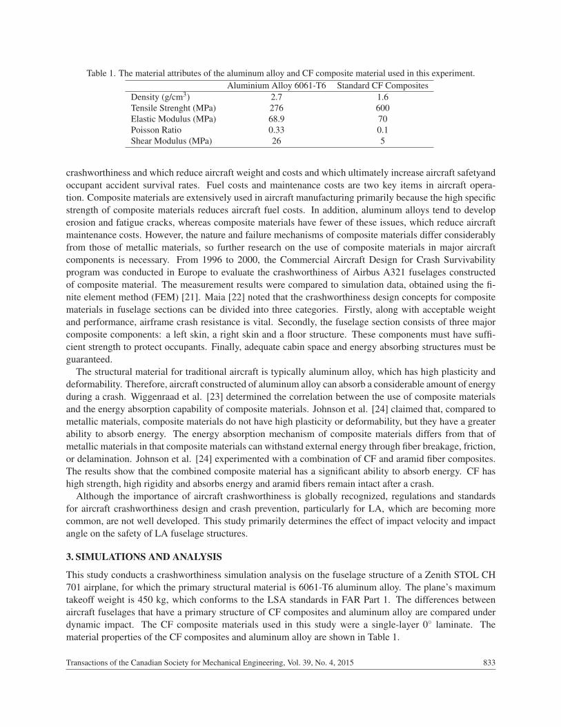
Table 1. The material attributes of the aluminum alloy and CF composite material used in this experiment.Aluminium Alloy 6061-T6 Standard CF Composites
Density (g/cm3) 2.7 1.6Tensile Strenght (MPa) 276 600Elastic Modulus (MPa) 68.9 70Poisson Ratio 0.33 0.1Shear Modulus (MPa) 26 5
crashworthiness and which reduce aircraft weight and costs and which ultimately increase aircraft safetyandoccupant accident survival rates. Fuel costs and maintenance costs are two key items in aircraft opera-tion. Composite materials are extensively used in aircraft manufacturing primarily because the high specificstrength of composite materials reduces aircraft fuel costs. In addition, aluminum alloys tend to developerosion and fatigue cracks, whereas composite materials have fewer of these issues, which reduce aircraftmaintenance costs. However, the nature and failure mechanisms of composite materials differ considerablyfrom those of metallic materials, so further research on the use of composite materials in major aircraftcomponents is necessary. From 1996 to 2000, the Commercial Aircraft Design for Crash Survivabilityprogram was conducted in Europe to evaluate the crashworthiness of Airbus A321 fuselages constructedof composite material. The measurement results were compared to simulation data, obtained using the fi-nite element method (FEM) [21]. Maia [22] noted that the crashworthiness design concepts for compositematerials in fuselage sections can be divided into three categories. Firstly, along with acceptable weightand performance, airframe crash resistance is vital. Secondly, the fuselage section consists of three majorcomposite components: a left skin, a right skin and a floor structure. These components must have suffi-cient strength to protect occupants. Finally, adequate cabin space and energy absorbing structures must beguaranteed.
The structural material for traditional aircraft is typically aluminum alloy, which has high plasticity anddeformability. Therefore, aircraft constructed of aluminum alloy can absorb a considerable amount of energyduring a crash. Wiggenraad et al. [23] determined the correlation between the use of composite materialsand the energy absorption capability of composite materials. Johnson et al. [24] claimed that, compared tometallic materials, composite materials do not have high plasticity or deformability, but they have a greaterability to absorb energy. The energy absorption mechanism of composite materials differs from that ofmetallic materials in that composite materials can withstand external energy through fiber breakage, friction,or delamination. Johnson et al. [24] experimented with a combination of CF and aramid fiber composites.The results show that the combined composite material has a significant ability to absorb energy. CF hashigh strength, high rigidity and absorbs energy and aramid fibers remain intact after a crash.
Although the importance of aircraft crashworthiness is globally recognized, regulations and standardsfor aircraft crashworthiness design and crash prevention, particularly for LA, which are becoming morecommon, are not well developed. This study primarily determines the effect of impact velocity and impactangle on the safety of LA fuselage structures.
3. SIMULATIONS AND ANALYSIS
This study conducts a crashworthiness simulation analysis on the fuselage structure of a Zenith STOL CH701 airplane, for which the primary structural material is 6061-T6 aluminum alloy. The plane’s maximumtakeoff weight is 450 kg, which conforms to the LSA standards in FAR Part 1. The differences betweenaircraft fuselages that have a primary structure of CF composites and aluminum alloy are compared underdynamic impact. The CF composite materials used in this study were a single-layer 0◦ laminate. Thematerial properties of the CF composites and aluminum alloy are shown in Table 1.
Transactions of the Canadian Society for Mechanical Engineering, Vol. 39, No. 4, 2015 833
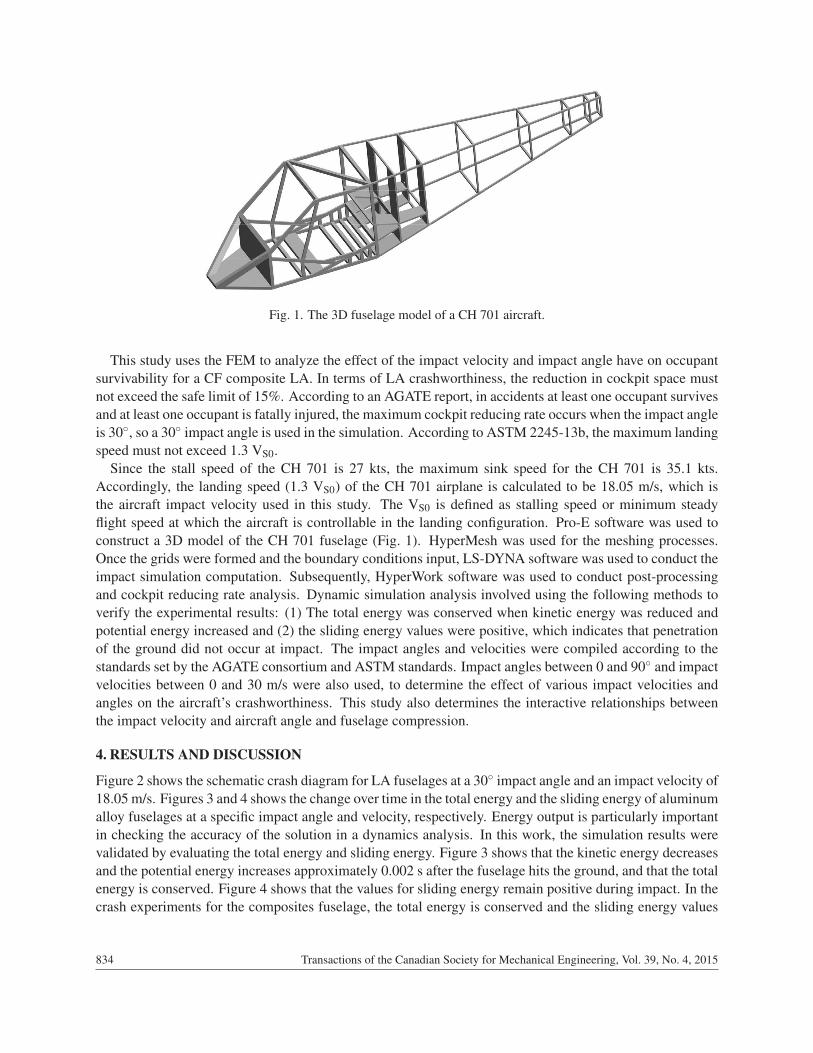
Fig. 1. The 3D fuselage model of a CH 701 aircraft.
This study uses the FEM to analyze the effect of the impact velocity and impact angle have on occupantsurvivability for a CF composite LA. In terms of LA crashworthiness, the reduction in cockpit space mustnot exceed the safe limit of 15%. According to an AGATE report, in accidents at least one occupant survivesand at least one occupant is fatally injured, the maximum cockpit reducing rate occurs when the impact angleis 30◦, so a 30◦ impact angle is used in the simulation. According to ASTM 2245-13b, the maximum landingspeed must not exceed 1.3 VS0.
Since the stall speed of the CH 701 is 27 kts, the maximum sink speed for the CH 701 is 35.1 kts.Accordingly, the landing speed (1.3 VS0) of the CH 701 airplane is calculated to be 18.05 m/s, which isthe aircraft impact velocity used in this study. The VS0 is defined as stalling speed or minimum steadyflight speed at which the aircraft is controllable in the landing configuration. Pro-E software was used toconstruct a 3D model of the CH 701 fuselage (Fig. 1). HyperMesh was used for the meshing processes.Once the grids were formed and the boundary conditions input, LS-DYNA software was used to conduct theimpact simulation computation. Subsequently, HyperWork software was used to conduct post-processingand cockpit reducing rate analysis. Dynamic simulation analysis involved using the following methods toverify the experimental results: (1) The total energy was conserved when kinetic energy was reduced andpotential energy increased and (2) the sliding energy values were positive, which indicates that penetrationof the ground did not occur at impact. The impact angles and velocities were compiled according to thestandards set by the AGATE consortium and ASTM standards. Impact angles between 0 and 90◦ and impactvelocities between 0 and 30 m/s were also used, to determine the effect of various impact velocities andangles on the aircraft’s crashworthiness. This study also determines the interactive relationships betweenthe impact velocity and aircraft angle and fuselage compression.
4. RESULTS AND DISCUSSION
Figure 2 shows the schematic crash diagram for LA fuselages at a 30◦ impact angle and an impact velocity of18.05 m/s. Figures 3 and 4 shows the change over time in the total energy and the sliding energy of aluminumalloy fuselages at a specific impact angle and velocity, respectively. Energy output is particularly importantin checking the accuracy of the solution in a dynamics analysis. In this work, the simulation results werevalidated by evaluating the total energy and sliding energy. Figure 3 shows that the kinetic energy decreasesand the potential energy increases approximately 0.002 s after the fuselage hits the ground, and that the totalenergy is conserved. Figure 4 shows that the values for sliding energy remain positive during impact. In thecrash experiments for the composites fuselage, the total energy is conserved and the sliding energy values
834 Transactions of the Canadian Society for Mechanical Engineering, Vol. 39, No. 4, 2015
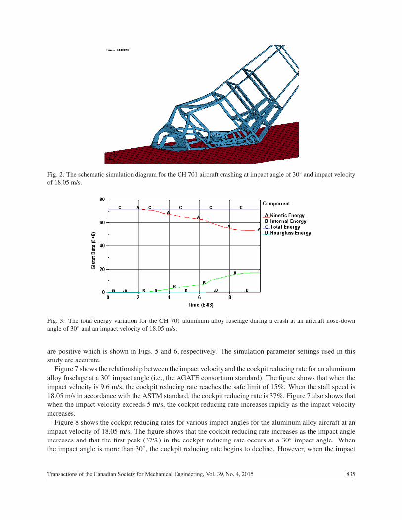
Fig. 2. The schematic simulation diagram for the CH 701 aircraft crashing at impact angle of 30◦ and impact velocityof 18.05 m/s.
Fig. 3. The total energy variation for the CH 701 aluminum alloy fuselage during a crash at an aircraft nose-downangle of 30◦ and an impact velocity of 18.05 m/s.
are positive which is shown in Figs. 5 and 6, respectively. The simulation parameter settings used in thisstudy are accurate.
Figure 7 shows the relationship between the impact velocity and the cockpit reducing rate for an aluminumalloy fuselage at a 30◦ impact angle (i.e., the AGATE consortium standard). The figure shows that when theimpact velocity is 9.6 m/s, the cockpit reducing rate reaches the safe limit of 15%. When the stall speed is18.05 m/s in accordance with the ASTM standard, the cockpit reducing rate is 37%. Figure 7 also shows thatwhen the impact velocity exceeds 5 m/s, the cockpit reducing rate increases rapidly as the impact velocityincreases.
Figure 8 shows the cockpit reducing rates for various impact angles for the aluminum alloy aircraft at animpact velocity of 18.05 m/s. The figure shows that the cockpit reducing rate increases as the impact angleincreases and that the first peak (37%) in the cockpit reducing rate occurs at a 30◦ impact angle. Whenthe impact angle is more than 30◦, the cockpit reducing rate begins to decline. However, when the impact
Transactions of the Canadian Society for Mechanical Engineering, Vol. 39, No. 4, 2015 835

Fig. 4. The sliding energy variation for the CH 701 aluminum alloy fuselage during a crash at an aircraft nose-downangle of 30◦ and an impact velocity of 18.05 m/s.
Fig. 5. The total energy variation for the CH 701 CF composites fuselage during a crash at an aircraft nose-down angleof 30◦ and an impact velocity of 18.05 m/s.
Fig. 6. The sliding energy variation for the CH 701 CF composites fuselage during a crash at an aircraft nose-downangle of 30◦ and an impact velocity of 18.05 m/s.
836 Transactions of the Canadian Society for Mechanical Engineering, Vol. 39, No. 4, 2015

Fig. 7. The relationship between the cockpit reducing rate and the impact velocity for an aluminum alloy fuselage ata 30◦ impact angle.
Fig. 8. The relationship between the cockpit reducing rate and the impact angle for an aluminum alloy fuselage at a18.05 m/s impact velocity.
angle exceeds 60◦, the cockpit reducing rate begins to rise again. When the impact angle is between 35◦ and65◦, lateral fuselage deformation increases faster than longitudinal deformation. Therefore, the longitudinalreducing rate for the fuselage cockpit at impact angles decreases between 35◦ and 65◦. The maximumfuselage reducing rate (i.e., 43.8%) occurs when the impact angle is 90◦. Figure 8 shows that the safe limitfor the aluminum alloy aircraft is reached when the impact velocity is 18.05 m/s and the impact angle is16.5◦.
Transactions of the Canadian Society for Mechanical Engineering, Vol. 39, No. 4, 2015 837

Fig. 9. The safe crash zone for an aluminium alloy fuselage at a cockpit reducing rate of less than 15%.
Figure 9 shows the safe crash zones for various impact speeds and impact angles for an aluminum alloyfuselage at cockpit reducing rates commensurate with the MIL-STD-1290A standard of 15%. At impactangles of between 0 and 20◦, the aircraft is almost sliding along the ground when it crashes, so this zonehas the maximum safety range. When the impact angle is between 0 and 35◦, the safety zones decrease asthe impact angle increases. The lowest points in the safety zones are for an impact angle of either 35◦ orbetween 80 and 90◦, where the maximum allowable impact velocity is only 8 m/s. In addition to the safetyzone when the impact angle is between 0 and 20◦, there is another comparatively safe zone when the impactangle is between 50 and 70◦. For this range of impact angles, at a 55◦ impact angle, the safe impact velocityis 16 m/s, which is approximately twice as much as the maximum safe velocity (8.3 m/s) for a 35◦ impactangle.
Figures 10 and 11 show the relationships between the impact velocity, the angle of impact, and the cockpitreducing rate for a CF composite fuselage. Figure 10 shows that when the impact velocity is between 0 and4 m/s, the variation in the cockpit reducing rate is negligible, but when the impact velocity is between 4 and18.05 m/s, the cockpit reducing rate increases slowly. When the stall speed conforms to the ASTM standard(18.05 m/s), the maximum cockpit reducing rate is only 2.5%. Figure 11 shows that when the impact velocityis 18.05 m/s (based on the ASTM standard), the cockpit reducing rate is minimal for impact angles between0 and 15◦. When the impact angle is between 15 and 80◦, the cockpit reducing rate increases slowly as theimpact angle increases and at an impact angle in excess of 80◦, the cockpit reducing rate increases rapidly.The cockpit reducing rate exceeds the standard 15% only when the impact angle is almost 90◦.
Figure 12 shows the safe crash zones for various impact velocities and impact angles for a compositematerial fuselage at a 15% cockpit reducing rate. The figure shows that when the impact angle for thecomposite material fuselage is less than 75◦ at impact, the fuselage can withstand an impact velocity ofat least 30 m/s, with no substantial increase in the cockpit reducing rate. The unsafe zone for compositematerial aircraft crashes occurs when the impact angle exceeds 75◦. For aircraft that impact the groundalmost vertically, the allowable impact speed is approximately 17.2 m/s.
838 Transactions of the Canadian Society for Mechanical Engineering, Vol. 39, No. 4, 2015
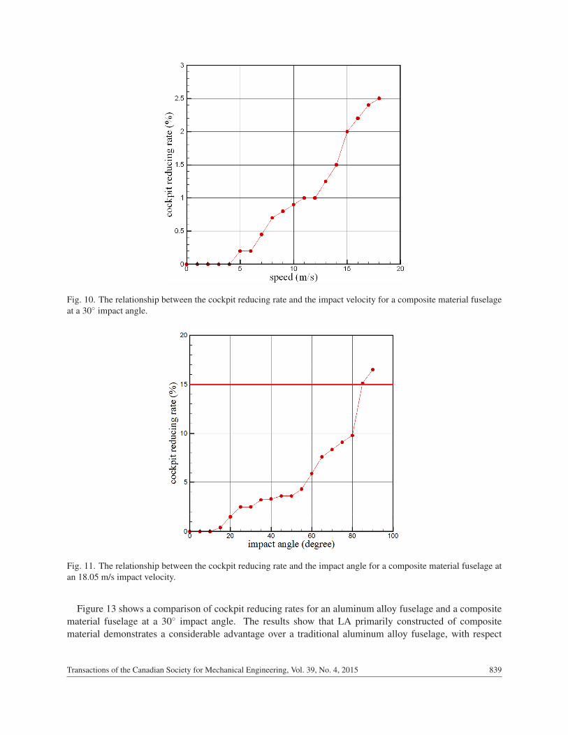
Fig. 10. The relationship between the cockpit reducing rate and the impact velocity for a composite material fuselageat a 30◦ impact angle.
Fig. 11. The relationship between the cockpit reducing rate and the impact angle for a composite material fuselage atan 18.05 m/s impact velocity.
Figure 13 shows a comparison of cockpit reducing rates for an aluminum alloy fuselage and a compositematerial fuselage at a 30◦ impact angle. The results show that LA primarily constructed of compositematerial demonstrates a considerable advantage over a traditional aluminum alloy fuselage, with respect
Transactions of the Canadian Society for Mechanical Engineering, Vol. 39, No. 4, 2015 839

Fig. 12. The safe crash zone for a composite material fuselage at a cockpit reducing rate of less than 15%.
Fig. 13. The cockpit reducing rate for an aluminum alloy fuselage and a composite material fuselage at differentimpact velocities.
to the maximum safe impact velocity. Figure 14 shows a comparison of the effect of the impact angle onthe cockpit reducing rate for an aluminum alloy fuselage and a composite material fuselage at the ASTM
840 Transactions of the Canadian Society for Mechanical Engineering, Vol. 39, No. 4, 2015

Fig. 14. The cockpit reducing rate for an aluminum alloy fuselage and a composite material fuselage at differentimpact angles.
Fig. 15. The safety zones for a LA constructed of different materials, for various impact angles and velocities.
Transactions of the Canadian Society for Mechanical Engineering, Vol. 39, No. 4, 2015 841

standard stall speed of 18.05 m/s. The figure shows that an aluminum alloy fuselage conforms to the AGATEboundary condition for occupant survivability at a 30◦ impact angle. The longitudinal cabin deformationrate decreases when the impact angle for an aluminum alloy fuselage exceeds 30◦, because a compressedfuselage results in a greater lateral deformation rate than longitudinal deformation rate. Compared with thecrash results for an aluminum alloy fuselage, the cockpit reducing rate for a composite material fuselageincreased slowly at a 30◦ impact angle. Figure 15 shows the various fuselage material safety zones forimpact angles from 0◦ to 90◦ and for impact velocities from 0 to 30 m/s. The results show that the safetyrange for a composite material fuselage in a crash is 1.66 times larger than that for an aluminum alloyfuselage.
5. CONCLUSIONS
This study uses numerical analysis software to compare the crashworthiness simulation results for an alu-minum alloy and a CF composite LA. The experimental parameters for the crash primarily use the LAstalling speeds required by ASTM and the impact angles of the AGATE consortium. The accuracy of thesimulation parameters is verified, based on the total energy being conserved and the variation on slidingenergy. The crash safety limits for LA that are constructed from two materials are compared and the resultsare as follows.
1. A fuselages constructed of composite materials is 41% lighter than an aluminum alloy fuselage.
2. When the impact angle for an aluminum aircraft is 30◦, the cockpit reducing rate reaches the safe limitof 15% at a stall speed of 9.6 m/s, whereas at an impact velocity of 18.05 m/s, the cockpit reducingrate is 37%. Conversely, for the same impact angle (i.e., 30◦), a CF composite aircraft has a cockpitreducing rate of 2.5% at an 18.05 m/s impact velocity. Therefore, the use of CF composites as thestructural material for LA provides high safety levels during a high-speed crash.
3. When an aluminum alloy fuselage crashes at a stall speed of 18.05 m/s, in accordance with the ASTMstandard, the cockpit reducing rate reaches the 15% limit at a 16.5◦ impact angle and the highestcockpit reducing rate occurs at a 30◦ impact angle. Angles between 0 and 85◦ are considered. Thisresult agrees with to the LA accident statistics published by the AGATE consortium. However, forimpact angles between 0 and 90◦ for the composite material aircraft, there is no crucial impact angle(unlike the 30◦ angle for the aluminum alloy aircraft). An excessive cockpit reducing rate is generatedwhen the composite material aircraft crashes at an impact angle in excess of 85◦.
4. This study determines the crash safety ranges for LA in terms of two variables: the impact angle andthe impact velocity. The crash safety range for an aluminum alloy aircraft decreases as the impactangle increases. During a crash, the safety impact angle and the velocity range is substantially greaterfor a composite material aircraft (approximately 160% of that for an aluminum alloy aircraft). There-fore, when the maximum cockpit reducing rate is 15%, a composite material aircraft provides greateroccupant survivability than a traditional aluminum alloy aircraft.
REFERENCES
1. Chambers, J.R., “Innovation in flight: Research of the NASA Langley Research Center on revolutionary ad-vanced concepts for aeronautics”, NASA SP-2005-4539, August 2005.
2. “Small aircraft propulsion: The future is here”, Fact Sheet FS-2000-04-001-GRC, NASA, November 24, 2004.3. “Small aircraft transportation system”, Fact Sheet FS-2001-03-59-LaRC, NASA, 2001.4. Annual Review of Aircraft Accident Data, U.S. General Aviation, Calendar Year 2005, National Transportation
Safety Board, NTSB/ARG-09/01, May 26, 2009.
842 Transactions of the Canadian Society for Mechanical Engineering, Vol. 39, No. 4, 2015

5. Report of the Aviation Security Advisory Committee Working Group on General Aviation Airports Security,Transport Security Administration, October 1, 2003.
6. AOPA (Aircraft Owners and Pilot Association) Air Safety Foundation, 2007 Nall Report-Accidents Trends andFactors for 2006, 2007.
7. Black S., “Flying high on composite wings”, Composites, September 2008.8. “Light fixed and rotary-wing aircraft crash resistance”, MIL-STD-1290A (AV), 26 September 1988.9. “General aviation crashworthiness project, Phase three – Acceleration loads and velocity changes of surviv-
able general aviation accidents”, NTSB/SR-85/02, National Transportation Safety Board, Washington, DC, 4September 1995.
10. Soltis, S.J. and Olcott, J.W., “The development of dynamic performance standards for general aviation aircraftseats”, SAE 850853, Society of Automotive Engineers, Warrendale, Pennsylvania, April 1985.
11. " “Aircraft crash survival design guide”, AD-A218 434–438, Aviation Applied Technology Directorate, USArmy Aviation Research and Technology Activity (AVSCOM), February 1989.
12. Hurley, T.R. and Vandenburg, J.M., “Small airplane crashworthiness design guide”, AGATE-WP3.4-034043-036, April 12, 2002.
13. Hooper, S., Henderson, M. and Seneviratne, W., “Design and construction of a crashworthy composite airframe”,AGATE-WP3.4-034026-089, Rev. A, 1 March 2002.
14. Jackson, K.E. and Fasanella, E.L., “Test-analysis correlation of a crash simulation of a vertical drop test of acommuter-class aircraft”, U.S. Army Research Laboratory, 2008.
15. Kumakura, I., “Vertical drop test of a transport fuselage section”, SAE International, 2002-01-2997, 2002.16. " “Standard specification for design and performance of a light sport airplane”, ASTM F2245-13b, 1 September
2013.17. “Design standards for advanced ultra-light aeroplanes”, DS-10141 Amendment 003, Light Aircraft Manufac-
tures Association of Canada, 8 November 2004.18. “Post-impact fires resulting from small-aircraft accidents”, Safety Issues Investigation Report SII A05-01, Trans-
portation Safety Board of Canada, April 24, 2013.19. “Cerification specification for very light aeroplanes, CS-VLA”, European Aviation Safety Agency, Amend-
ment 1, March 5, 2009.20. European Vehicle Passive Safety Network 2, “Report: Task 5.6 – Aircraft Safety”, 25 February 2004.21. Delsart, D., Joly, D., Mahe, M. and Winkelmuller, G., “Evaluation of finite element modelling methodologies for
the design of crashworthy composite commercial aircraft fuselage”, in Proceedings 24th International Congressof the Aeronautical Sciences, 29 August 2004.
22. Maia, L.G., “Crashworthy composite fuselage section concept for next generation general aviation”, AdvancedComposite Solutions, ACS, 2005.
23. Wiggenraad J.F.M., Michielsen A.L.P.J., Santoro D., Lepage F., Kindervater C. And Beltran F., “Develop of aCrashworthy Composite Fuselage Structure for a Commuter Aircraft”, NLR-TP-99532, 1999.
24. Johnson A.F., Kindervater C.M., Thuis H.G.S.J. and Wiggenraad J.F.M., “Crash Resistant Composite SubfloorStructures for Helicopters”, AGARD FVP-Symposium: Advances in Rotorcraft Technology, CP-592, May 1996.
Transactions of the Canadian Society for Mechanical Engineering, Vol. 39, No. 4, 2015 843