Embed Size (px)
Citation preview

1
�rbhft
rs�thitwcbrcoltbghF
ab
iSN
J
Downloaded Fr
Denise A. McKay1
Picker Engineering Program,Smith College,
Northampton, MA 01063e-mail: [email protected]
Anna G. StefanopoulouFellow ASME
Jeffrey Cook
Fuel Cell Control Laboratory,University of Michigan,
Ann Arbor, MI 48109
A Controllable Membrane-TypeHumidifier for Fuel CellApplications—Part II: ControllerDesign, Analysis andImplementationA membrane-based gas humidification apparatus was employed to actively manage theamount of water vapor entrained in the reactant gas supplied to a fuel cell stack. Thehumidification system utilizes a gas bypass and a series of heaters to achieve accurateand fast humidity and temperature control. A change in fuel cell load induces a reactantmass flow rate disturbance to this humidification system. If not well regulated, this dis-turbance creates undesirable condensation and evaporation dynamics, both to the hu-midification system and the fuel cell stack. Therefore, controllers were devised, tuned, andemployed for temperature reference tracking and disturbance rejection. Two heater con-troller types were explored: on-off (thermostatic) and variable (proportional integral), toexamine the ability of the feedback system to achieve the control objectives with minimalhardware and software complexities. The coordination of the heaters and the bypassvalve is challenging during fast transients due to the different time scales, the actuatorconstraints, and the sensor responsiveness. �DOI: 10.1115/1.4001020�
IntroductionFor the advancement of polymer electrolyte membrane fuel cell
PEMFC� systems, achieving adequate thermal and humidityegulation remains a critical hurdle �1�. To maintain high mem-rane conductivity and durability, the supplied reactants requireumidification. However, excess water can condense and affectuel cell performance �2�, requiring accurate and fast control ofhe gas humidity supplied to the fuel cell �3�.
Several humidification strategies were considered for fuel celleactant pretreatment, including bubblers or spargers �4�, and pas-ive membrane-based humidifiers integral to the PEMFC stack2,5,6�. For active humidity and temperature control of the reac-ants supplied to a PEMFC stack, a stand-alone membrane-basedumidification system was designed and experimentally validatedn Part I of this work �7�. The humidification apparatus decoupleshe passive membrane humidifier from the PEMFC cooling loopsith the addition of an external gas bypass and a separate water
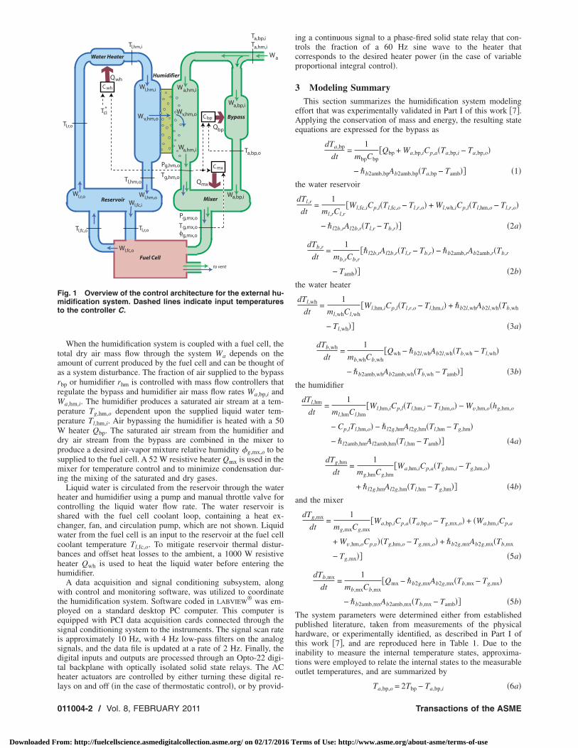
irculation system �PEMFC reactant exhaust streams could alsoe used�, to provide a controllable reactant relative humidity at aegulated temperature. This humidification system apparatus isonceptually similar to that proposed by Wheat et al. �8�. Theperation of the humidifier consists of a dry reactant gas andiquid water delivered to opposite sides of a membrane humidifiero produce a saturated gas. Another stream of dry reactant gasypasses the humidifier. The combination of the saturated and dryas streams produces a reactant-vapor mixture at a desired relativeumidity. A diagram of the humidification system is provided inig. 1.The humidification system control strategy in Ref. �8� relied onrelative humidity sensor for feedback control of an electronic
ypass valve, due to the strong coupling between gas humidity
1Corresponding author.Contributed by the Advanced Energy Systems Division of ASME for publication
n the JOURNAL OF FUEL CELL SCIENCE AND TECHNOLOGY. Manuscript receivedeptember 29, 2009; final manuscript received November 17, 2009; published online
ovember 1, 2010. Review conducted by Nigel M. Sammes.ournal of Fuel Cell Science and TechnologyCopyright © 20
om: http://fuelcellscience.asmedigitalcollection.asme.org/ on 02/17/2016 T
and temperature. However, thermal regulation must also be con-sidered. In developing our control strategy, critical steps were ac-complished by properly selecting the controller references usedfor temperature feedback; employing a static feedforward map-ping for humidity control to eliminate the need for an expensiveand slow relative humidity probe for feedback control; and pro-viding a thorough comparison of the use of on/off versus variablegas heaters in achieving thermal regulation.
Controllers were designed and a reproducible methodology forcontroller tuning is presented to coordinate the three resistiveheaters, as well as the mass fractional split of air flow between thehumidifier and the air bypass. These controllers must regulate thetemperature of the dry air leaving the bypass, and join the satu-rated air leaving the humidifier. Should the temperatures of thesetwo gas streams not be well regulated during air mass flow dis-turbances due to the fuel cell system load demand, condensationor dehydration will occur. Similar problems arise in engine ther-mal management systems, employing either a valve or servo mo-tor to bypass the coolant around the heat exchanger �9,10�. Thecoordination of the heaters and the bypass valve is challengingduring fast transients due to the different time scales, the actuatorconstraints, and the sensor responsiveness.
2 Hardware and System OverviewThe humidification system hardware, designed in collaboration
with the Schatz Energy Research Center at Humboldt State Uni-versity, was installed in the Fuel Cell Control Laboratory at theUniversity of Michigan. A detailed description of the system ac-tuators and sensors was provided in Part I of this work �7�. Thesystem was designed to deliver moist air at 45°C–65°C and 50–100% relative humidity at dry air mass flow rates up to 40 slm,corresponding to 300% excess oxygen in the cathode of a 0.5 kWfuel cell. The humidifier system consists of five control volumes,namely, the water heater, humidifier, reservoir, bypass, and mixer.Figure 1 shows the interaction of the air and liquid water as they
move through these control volumes.FEBRUARY 2011, Vol. 8 / 011004-111 by ASME
erms of Use: http://www.asme.org/about-asme/terms-of-use
taarrWppWdpsmi
hcscwcbhh
wtpesisdthl
Fmt
0
Downloaded Fr
When the humidification system is coupled with a fuel cell, theotal dry air mass flow through the system Wa depends on themount of current produced by the fuel cell and can be thought ofs a system disturbance. The fraction of air supplied to the bypassbp or humidifier rhm is controlled with mass flow controllers thategulate the bypass and humidifier air mass flow rates Wa,bp,i and
a,hm,i. The humidifier produces a saturated air stream at a tem-erature Tg,hm,o dependent upon the supplied liquid water tem-erature Tl,hm,i. Air bypassing the humidifier is heated with a 50
heater Qbp. The saturated air stream from the humidifier andry air stream from the bypass are combined in the mixer toroduce a desired air-vapor mixture relative humidity �g,mx,o to beupplied to the fuel cell. A 52 W resistive heater Qmx is used in theixer for temperature control and to minimize condensation dur-
ng the mixing of the saturated and dry gases.Liquid water is circulated from the reservoir through the water
eater and humidifier using a pump and manual throttle valve forontrolling the liquid water flow rate. The water reservoir ishared with the fuel cell coolant loop, containing a heat ex-hanger, fan, and circulation pump, which are not shown. Liquidater from the fuel cell is an input to the reservoir at the fuel cell
oolant temperature Tl,fc,o. To mitigate reservoir thermal distur-ances and offset heat losses to the ambient, a 1000 W resistiveeater Qwh is used to heat the liquid water before entering theumidifier.
A data acquisition and signal conditioning subsystem, alongith control and monitoring software, was utilized to coordinate
he humidification system. Software coded in LABVIEW® was em-
loyed on a standard desktop PC computer. This computer isquipped with PCI data acquisition cards connected through theignal conditioning system to the instruments. The signal scan rates approximately 10 Hz, with 4 Hz low-pass filters on the analogignals, and the data file is updated at a rate of 2 Hz. Finally, theigital inputs and outputs are processed through an Opto-22 digi-al backplane with optically isolated solid state relays. The ACeater actuators are controlled by either turning these digital re-
Humidifier
Bypass
Water Heater
Reservoir Mixer
Fuel Cell
to vent
Qmx
Tg,mx,oφg,mx,o
Pg,mx,o
Tg,hm,o
Pg,hm,o
Wa,bp,i
Wa,hm,i
v,hm,oWv,hm,oW
Wl,hm,o
Wl,hm,i
Tl,hm,o
Wl,fc,o
Wl,fc,i
Wl,r,o
Tl,r,o
Tl,r,oTl,fc,o
Tl,hm,i
Qbp
Wa
Ta,hm,i
Ta,bp,i
Wa,hm,i
Wa,bp,i
Ta,bp,o
Qwh
Cbp
Cmx
Cwh
Tci*
ig. 1 Overview of the control architecture for the external hu-idification system. Dashed lines indicate input temperatures
o the controller C.
ays on and off �in the case of thermostatic control�, or by provid-
11004-2 / Vol. 8, FEBRUARY 2011
om: http://fuelcellscience.asmedigitalcollection.asme.org/ on 02/17/2016 T
ing a continuous signal to a phase-fired solid state relay that con-trols the fraction of a 60 Hz sine wave to the heater thatcorresponds to the desired heater power �in the case of variableproportional integral control�.
3 Modeling SummaryThis section summarizes the humidification system modeling
effort that was experimentally validated in Part I of this work �7�.Applying the conservation of mass and energy, the resulting stateequations are expressed for the bypass as
dTa,bp
dt=
1
mbpCbp�Qbp + Wa,bp,iCp,a�Ta,bp,i − Ta,bp,o�
− �b2amb,bpAb2amb,bp�Ta,bp − Tamb�� �1�the water reservoir
dTl,r
dt=
1
ml,rCl,r�Wl,fc,iCp,l�Tl,fc,o − Tl,r,o� + Wl,wh,iCp,l�Tl,hm,o − Tl,r,o�
− �l2b,rAl2b,r�Tl,r − Tb,r�� �2a�
dTb,r
dt=
1
mb,rCb,r��l2b,rAl2b,r�Tl,r − Tb,r� − �b2amb,rAb2amb,r�Tb,r
− Tamb�� �2b�the water heater
dTl,wh
dt=
1
ml,whCl,wh�Wl,hm,iCp,l�Tl,r,o − Tl,hm,i� + �b2l,whAb2l,wh�Tb,wh
− Tl,wh�� �3a�
dTb,wh
dt=
1
mb,whCb,wh�Qwh − �b2l,whAb2l,wh�Tb,wh − Tl,wh�
− �b2amb,whAb2amb,wh�Tb,wh − Tamb�� �3b�the humidifier
dTl,hm
dt=
1
ml,hmCl,hm�Wl,hm,iCp,l�Tl,hm,i − Tl,hm,o� − Wv,hm,o�hg,hm,o
− Cp,lTl,hm,o� − �l2g,hmAl2g,hm�Tl,hm − Tg,hm�
− �l2amb,hmAl2amb,hm�Tl,hm − Tamb�� �4a�
dTg,hm
dt=
1
mg,hmCg,hm�Wa,hm,iCp,a�Tg,hm,i − Tg,hm,o�
+ �l2g,hmAl2g,hm�Tl,hm − Tg,hm�� �4b�and the mixer
dTg,mx
dt=
1
mg,mxCg,mx�Wa,bp,iCp,a�Ta,bp,o − Tg,mx,o� + �Wa,hm,iCp,a
+ Wv,hm,oCp,v��Tg,hm,o − Tg,mx,o� + �b2g,mxAb2g,mx�Tb,mx
− Tg,mx�� �5a�
dTb,mx
dt=
1
mb,mxCb,mx�Qmx − �b2g,mxAb2g,mx�Tb,mx − Tg,mx�
− �b2amb,mxAb2amb,mx�Tb,mx − Tamb�� �5b�The system parameters were determined either from establishedpublished literature, taken from measurements of the physicalhardware, or experimentally identified, as described in Part I ofthis work �7�, and are reproduced here in Table 1. Due to theinability to measure the internal temperature states, approxima-tions were employed to relate the internal states to the measurableoutlet temperatures, and are summarized by
Ta,bp,o = 2Tbp − Ta,bp,i �6a�
Transactions of the ASME
erms of Use: http://www.asme.org/about-asme/terms-of-use

Fb
TFfrmTt
M�
mmmmmmmmm
J
Downloaded Fr
Tl,wh,o = 2Tl,wh − Tl,r,o �6b�
Tl,hm,o = 2Tl,hm − Tl,hm,i �6c�
Tl,r,o = Tl,r �6d�
Ta,hm,o = 2Ta,hm − Ta,hm,i �6e�
Tg,mx = Tg,mx,o �6f�
inally, the relative humidity of the mixer outlet gas is estimatedy
�g,mx,o = �g,hm,orhmpg,hm,o
sat
pg,mx,osat � pg,mx,o
pg,hm,o − rbp�g,hm,opg,hm,osat � �7�
he locations of the measurements and disturbances are shown inig. 1. The inputs to the system are heater power Q and the massraction of air diverted through the bypass rbp; the states are theespective temperatures T; the disturbances are the total dry airass flow rate Wa, the air temperature supplied to the system
a,hm,i and Ta,bp,i, and the ambient temperature Tamb; and the sys-em output is the air relative humidity leaving the mixer �g,mx,o.
Table 1 Model parameters
assg�
Specific heat�J /kg K�
Area�m2�
Heat transfer�W /m2 K�
bp=80 Cbp=460 Abp=0.012 �bp=10.8–21822Wa,bp,i
l,wh=50 Cl,wh=4180 Ab2l,wh=0.020 �b2l,wh=139.8
b,wh=780 Cb,wh=460 Awh=0.028 �b2amb,wh=0
l,hm=240 Cl,hm=4180 Al2amb,hm=0.202 �l2amb,hm=22.5
a,hm=18 Ca,hm=983 Al2a,hm=0.03 �l2a,hm=41029Wa,hm,i0.95
g,mx=10 Cg,mx=863 Ab2g,mx=0.009 �b2g,mx=2819Wa0.54
b,mx=745 Cb,mx=460 Amx=0.012 �b2amb,mx=25.8
l,r=2800 Cl,r=4180 Al2b,r=0.075 �l2b,r=167.5
b,r=1540 Cb,r=957 Ab2amb,r=0.087 �b2amb,r=80.0Cp,a=1004Cp,v=1872Cp,l=4180
StaticFeedforwardAir Flow Map
WaterCirculation
SystemPlant
WaterHeater
Controller
Tci*
φci*
Pg,mx,o
Pg,hm,o
Wl,hm,i
+−
ewh Qwh
Tamb
Tg,hm,o+−
e b
Wa,hm,i
W a,bp,iTg,hm,o
Fig. 2 Humidification syst
ournal of Fuel Cell Science and Technology
om: http://fuelcellscience.asmedigitalcollection.asme.org/ on 02/17/2016 T
4 Controller System Architecture
With the model of the external humidification system presentedin Sec. 3, controllers were designed and tuned to coordinate thethree resistive heaters, as well as the fraction of air supplied to thehumidifier and bypass. The three heaters must be well coordinatedto regulate the system temperatures and mitigate the effect ofdisturbances.
An overview of the control architecture is provided in Fig. 2.An error signal is calculated �difference between the reference andactual temperatures� as an input to the heater controllers. Theheaters are then controlled by determining a desired heater powerfor the respective control volumes given the error signal. Thefractional split of dry air mass flow between the humidifier andthe bypass is commanded using a static nonlinear feedforwardmap given a desired relative humidity and temperature at the cath-ode inlet �mixer outlet�. This section introduces the nonlinearstatic feedforward mapping devised for air mass flow control, thereference temperatures used for thermal regulation, and the plantlinearization performed in preparation for controller tuning.
4.1 Nonlinear Feedforward for Air Mass Flow Control. Anonlinear, physics based, feedforward mapping is used to controlthe amount of air supplied to the bypass and the humidifier toachieve the desired relatively humidity of the gases leaving themixer and supplied to the cathode inlet of the PEMFC stack. Thisfeedforward mapping is a function of both the measured and de-sired temperature states, relative humidity estimations, and totalgas pressure measurements. The use of relative humidity feedbackcontrol would require either a water vapor mass flow rate or rela-tive humidity measurement at the mixer outlet. In practice, bothsuch measurements are prohibitively expensive, motivating therationale for using feedforward and neglecting relative humidityfeedback control. Although an observer based relative humidityfeedback estimation could be employed, the coupling betweenhumidity and temperature poses a performance tradeoff betweenthese two control objectives.
To calculate the desired split of dry air mass flow between thehumidifier and the bypass, mass conservation is applied. Assum-ing that in steady-state the mass flow rate of water vapor and airentering the mixer are equal to the mass flow rates leaving themixer, and applying the definition for the humidity ratio �
BypassHeater
Controller
BypassPlant
MixerPlant
Mixer HeaterController
Tamb
W a,bp,i
Qbp Ta,bp,o
+−
emx Qmx
Tamb
W a,bp,i
Wa,hm,i
g,mx,oT
p
em control architecture
FEBRUARY 2011, Vol. 8 / 011004-3
erms of Use: http://www.asme.org/about-asme/terms-of-use
=t
wem
heetnftb
ttrrctot
httsmdt
wtrcmswtat
rsrfsmctc
hbifss
0
Downloaded Fr
Mv�psat /Ma�p−�psat�, the required fraction of air supplied tohe humidifier rh=Wa,hm,i /Wa can be expressed as
rhm =�g,mx,o
� pg,mx,osat� �pg,hm,o − �g,hm,opg,hm,o
sat ��g,hm,opg,hm,o
sat �pg,mx,o − �g,mx,o� pg,mx,o
sat� ��8�
here a superscript � has been used to denote the desired refer-nce values. The commanded air mass flow rates through the hu-idifier and the bypass are
Wa,hm,i = rhmWa �9a�
Wa,bp,i = Wa − Wa,hm,i �9b�
4.2 Reference Temperatures. To properly coordinate theeaters using feedback control, reference temperatures must bestablished for the mixer, bypass, and humidifier air outlets. Therror, or difference between the reference and actual measuredemperatures, �e=�T�−�T, where � indicates a deviation fromominal conditions, can then be formulated into control objectivesor each of the heaters. It is important to note that these actualemperatures must be measured to implement direct �nonobserverased� feedback control.
Several reference temperature choices exist for thermal regula-ion of the humidification system, depending upon the responseimes of the bypass, mixer, and water circulation systems. Theseeference temperatures have drastically different implications withespect to controller performance. For example, if the water cir-ulation, bypass, and mixer systems had similar response times,hey could be independently coordinated, motivating the selectionf the desired cathode inlet temperature as the reference tempera-ure for all three systems.
It will be shown later in Sec. 4.3 that the intermediate step ofeating liquid water to raise the humidifier gas temperature causeshe slowest thermal response of the three systems. Because bothhe mixer and bypass systems are faster than the water circulationystem, condensation or evaporation can be avoided upon gasixing if both the mixer and the bypass track the temperature
ynamics of the water circulation system. The resulting referenceemperatures
Tg,mx,o� = Tg,hm,o, Tg,hm,o
� = Tca,i� , Ta,bp,o
� = Tg,hm,o �10�
ill result in a slower system thermal response, but will maintainhe desired relative humidity. Figure 1 shows the location of theseeference temperatures with the measured states and respectiveontrol volumes clearly indicated. An important distinction isade here, the reference temperature for the water circulation
ystem will be either constant or variable, depending upon theater management demands of the PEMFC stack. However, both
he mixer and bypass reference temperatures are always variablend depend on the dynamics in the water circulation system, nothe dynamics in the PEMFC stack.
This control strategy relies on the significant bandwidth sepa-ation observed between the slow closed loop water circulationystem and the fast bypass and mixer systems, and should beeconsidered if the volumes were designed to be significantly dif-erent than those presented in this work. Additionally, if the de-ired cathode inlet temperature were deemed to be more critical toaintain than relative humidity, the mixer could track the desired
athode inlet temperature, implying that the mixer heater is con-rolled irrespective of the bypass and water circulation systemonditions.
4.3 Plant Linearization. Due to the cascaded nature of theumidification system, the mixer and bypass control volumes cane analyzed separately from the water circulation system, allow-ng for independent controller design. The system of ordinary dif-erential equations, shown in Sec. 3, was expressed analytically intate space, where the control volume outlet temperatures repre-
ented the states, the heater actuators represented the system in-11004-4 / Vol. 8, FEBRUARY 2011
om: http://fuelcellscience.asmedigitalcollection.asme.org/ on 02/17/2016 T
puts, the air mass flow rate represented the system disturbance,and the liquid water mass flow rate and ambient temperature wereassumed to be constant.
Using this state space representation, the system was linearizedabout a set of nominal conditions, listed in Table 2. As previouslydiscussed, the humidification system was designed to regulate thecathode air supplied to an eight-cell PEMFC stack with an activearea of 300 cm2. Applying a 0.3 A /cm2 electric load to thisPEMFC stack requires 0.6 g/s of air at an air stoichiometry of250%. These nominal conditions were selected to approximate themidpoint of the expected stack operating range.
Transfer functions from the resistive heater inputs to the systemoutlet temperatures were then derived and the sensitivity of thepole locations to disturbances in the total air mass flow rate wasexamined. Table 3 summarizes the open loop time constants andDC-gains ��Tg,cv,o /�Qcv �s=0� for this range of air flow for each ofthe three systems. The total air mass flow rate range considered,Wa=0.3–0.9 g /s, represents a humidification system disturbancefor PEMFC stack electrical loads between 0.15–0.45 A /cm2.The linear and nonlinear systems were compared, both to steps inheater inputs and air mass flow rates, indicating that the linearsystem response well approximates the nonlinear system for smalldeviations from nominal conditions.
Transfer functions can also be expressed from the air flow dis-turbance to the outlet temperatures. However, the DC-gains ofthese transfer functions indicate that there is a very small changein the steady-state heat required for a change in air mass flow rate.As a result, the use of static feedforward to reject air flow distur-bances does not significantly improve temperature regulation.Therefore, only transfer functions from the heater inputs to thetemperature outputs will be presented here.
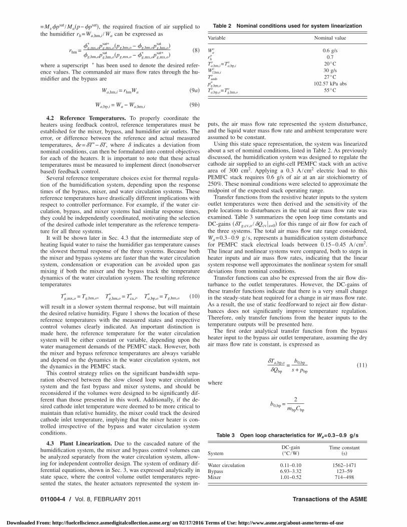
The first order analytical transfer function from the bypassheater input to the bypass air outlet temperature, assuming the dryair mass flow rate is constant, is expressed as
�Ta,bp,o
�Qbp=
b0,bp
s + pbp�11�
where
b0,bp =2
mbpCbp
Table 2 Nominal conditions used for system linearization
Variable Nominal value
Wao 0.6 g/s
rho 0.7
Ta,hm,io =Ta,bp,i
o 20°CWl,hm,i
o 30 g/sTamb
o 27°Cpg,hm,o
o 102.57 kPa absTa,bp,o
o =Tg,hm,oo 55°C
Table 3 Open loop characteristics for Wa=0.3–0.9 g/s
SystemDC-gain�°C /W�
Time constant�s�
Water circulation 0.11–0.10 1562–1471Bypass 6.93–3.32 123–59Mixer 1.01–0.52 714–498
Transactions of the ASME
erms of Use: http://www.asme.org/about-asme/terms-of-use

TtaclQbpt
h
wlthz=csslr
fidbimossiatl
tncrs�fp
w
Co
J
Downloaded Fr
pbp =2Wa,bp,i
o Cp,a + �b2amb,bpo Ab2amb,bp
mbpCbp� 0.013
he bypass pole location pbp is a function of the air mass flow ratehrough the bypass, which will influence the system response timend DC-gain �Ta,bp,o /�Qbp �s=0, as indicated in Table 3. An in-reased air mass flow rate causes an increase in the bypass poleocation, resulting in a faster response time and smaller DC-gain.ualitatively, a step in heat added to the bypass will increase theypass temperature by a smaller amount at high air flow, as com-ared with low air flow; or alternatively, more energy is requiredo maintain the system temperature as air flow increases.
A transfer function from the water heater actuator input to theumidifier air outlet temperature is expressed as
�Tg,hm,o
�Qhm=
b0�s + z1��s + pl,wh��s + pl,hm��s + pa,hm��s + pl,r��s + pb,r�
,
�12�
here the coefficient in the numerator b0 and the pole and zeroocations can be analytically represented as functions of the heatransfer coefficients, the control volume masses, and specificeats. At the nominal conditions, b0=3.39�10−6, the poles, andero are located at pa,hm=1.23, pl,hm=0.292, pl,r=0.090, pb,r6.6�10−4, pl,wh=0.014, and z1=0.0094, with a pole-zero can-ellation between z= pb,wh=0.016. The fastest control volume re-ponse time �pole location furthest from the origin on the complex-plane� is associated with the humidifier air, followed by theiquid water volumes. The bulk material volumes have the slowestesponse time.
By varying the nominal air mass flow rate through the humidi-er from Wa,hm,i=0.21–0.63 g /s, the open loop time constantecreases from 1562 s to 1471 s, respectively. Thus, as with theypass, the water circulation system response time increases forncreasing air mass flow rates. This change in the time constants is
ost influenced by the slowest pole, which varies from a locationn the real axis of the complex s-plane from s=−0.0007 to=−0.0009 across the range of humidifier air mass flow rates con-idered. Note that, although the pole locations are significantlynfluenced by the liquid water mass flow rate, this variable is not
disturbance to the system and can be regulated at a fixed valuehroughout the experiments. As a result, the sensitivity of the poleocations to liquid water flow is not considered here.
The mixer thermal dynamics are described by a two state sys-em, including the air-vapor mixture and the bulk materials. At theominal conditions, the pole associated with the gas state is lo-ated at s=−0.132, while the pole associated with the bulk mate-ials is located at s=−0.0017, indicating a significant bandwidtheparation between these two states. As a result, assuming thatTg,mx,o /dt=0, which is a first order analytical transfer functionrom the mixer heater input to the gas outlet temperature, is ex-ressed by
�Tg,mx,o
�Qmx=
b0,mx
s + pmx�13�
here
b0,mx = �b2g,mxo Ab2g,mx/�3,mx
�1,mx = �b2amb,mxAmx + �b2g,mxo Ab2g,mx
�2,mx = �WaoCp,a + Wv,hm,o
o Cp,v�
�3,mx = mb,mxCb,mx��2,mx + �b2g,mxo Ab2g,mx�
pmx =�1,mx�2,mx + �b2amb,mxAmx�b2g,mx
o Ab2g,mx
�3,mx
omparing the nonlinear full order model to this linear reduced
rder model of the mixer thermal dynamics during step changes inournal of Fuel Cell Science and Technology
om: http://fuelcellscience.asmedigitalcollection.asme.org/ on 02/17/2016 T
the mixer heat shows an insignificant difference between the twodynamic models.
Clearly, the mixer pole location is a function of the air massflow rate, either directly or indirectly through the heat transfercoefficient �between the bulk materials and the gases� or the watervapor mass flow rate. By varying the air mass flow rate fromWa=0.3–0.9 g /s, the pole location moves from s=−0.0014 to s=−0.0020, the time constant to a step in heat decreases from 714s to 498 s, and the DC-gain decreases from 1.01°C /W to0.52°C /W. As expected, by comparing the DC-gains of the by-pass and mixer, more energy is required to raise the mixer tem-perature due to the larger air mass and the presence of water vaporin the mixer.
5 Thermostatic ControlA simple and inexpensive control strategy for temperature regu-
lation of a thermal system involves cycling a two position heateron or off at specified thresholds, as commonly implemented withthermostats. Thermostatic control is widely used for industrial au-tomatic feedback systems due to its simplicity and cost effective-ness. A commonly recognized disadvantage to thermostatic con-trol is the cycling of the actuator due to the repeated on-off actionresulting from sensor noise. To reduce this cycling, hysteresis isoften incorporated to construct a region about the desired tem-perature for which no control action takes place, known as thedifferential gap �11�. Figure 3 relates the error signal e to thecontrol input Q for this thermostatic controller with hysteresis.Refer back to Figs. 1 and 2 for illustrations of the signal pathsdetailing the controllers and plants for the humidification feedbackcontrol system.
Temperature error dead bands establish the boundaries of thedifferential gap. When the temperature error e=T�−T is less thanthe lower error bound e�−es, the heater is on Q=Qmax. When thetemperature error is greater than the higher error bound e�es, theheater is off �Q=0�. For errors within the error bounds, there ishysteresis, such that the heater is either on or off, depending uponthe previous state of the heater. In this application, the resistiveheater has been modeled as a nonideal relay, where the actuator“off” position is Q=0. For an ideal relay, the actuator off positionwould be −Qmax. This is an important distinction, which will bediscussed in more detail later. In summary, the discrete time ther-mostatic control law is represented by
u�k� = Qmax for e�k� − es
0 for es e�k�u�k − 1� for − es � e�k� � es
�14�
Some degree of temperature overshoot �e�� �es� is expected afterthe heater changes state; thus, the steady temperature response isoscillatory. The frequency and magnitude of these induced limitcycle oscillations depend on the system thermal dynamics and theerror bounds es. The error bound will be selected to keep the errore within a specified limit cycle amplitude a.
Selecting this error bound es is not trivial. Both a describing
errores- e 0
0
Q
Qmax
Differential Gap
s
Fig. 3 Thermostatic control signal versus temperature error
function methodology, as well as a simulation based strategy, were
FEBRUARY 2011, Vol. 8 / 011004-5
erms of Use: http://www.asme.org/about-asme/terms-of-use

etwtTts
FafDqa
hddaactd
w
mtatedraGIc
S
BMW
Fl
0
Downloaded Fr
mployed to tune the thermostatic controllers for the three resis-ive heaters. Table 4 summarizes the calculated amplitude and,here applicable, the temperature limit cycle period for each of
he three regulated systems evaluated at the nominal conditions.he specific methodologies employed for each thermostatic con-
roller to produce these results are detailed in the following sub-ections.
5.1 Water Circulation System Tuning With Describingunction Method. The behavior of a system nonlinearity, such asrelay, can be analytically evaluated by constructing a describing
unction that approximates the nonlinear response of the relay.escribing functions were used to quantify the amplitude and fre-uency of limit cycles induced in relay feedback systems �12,13�,nd subsequently used in the tuning of process controllers �14�.
The describing function that approximates the behavior of aysteretic relay nonlinearity was derived for a relay, which pro-uces either a positive or negative output, such as u= Qmax,epending upon the state of the relay �15�. The physical heaterctuators employed, however, do not allow negative heat to bedded to the control volume, as shown by the on-off thermostaticontrol law specified in Eq. �14�. As a result, the describing func-ion in Ref. �15� was shifted and scaled �as shown in Fig. 4�, toerive the describing function for a shifted relay with hysteresis
N�a�,es� =Qmax
2� 4
�a���1 − � es
a��2
− jes
a�� + 1 �15�
here a� is the desired temperature limit cycle amplitude.In a relay feedback system, the output temperature of the ther-al process �T�s�=G�s��Q�s�, where G�s� denotes the plant
ransfer function �shown in Sec. 4.3�, oscillates with a temperaturemplitude of a and frequency �. Assuming there is no change inhe reference temperature and no disturbances to the system, therror bound es and the resulting frequency of oscillation � can beetermined for a given desired amplitude a� by satisfying both theeal and imaginary parts of G�j��N�a� ,es�=−1+0j. Alternatively,
range of es values could be selected and the intersection of�j��N�a� ,es� with the point −1+0j could be found graphically.
n general, as the differential gap expands, implying that es in-reases, the resulting limit cycle oscillation amplitude increases
Table 4 Summary of thermostatic control results
ystemError bound
�°C�Amplitude
�°C�Period
�s�
ypass 0.38 0.5 2ixer 0.38 1.0 n/aater circulation 0.21 0.5 58
e 1
-1e
Q
Qmaxu
Unshifted
Qmaxu
Shifted
e
1
+
+2
1
-1e
Q
ig. 4 Schematic comparing an unshifted versus a shifted re-
ay with hysteresis11004-6 / Vol. 8, FEBRUARY 2011
om: http://fuelcellscience.asmedigitalcollection.asme.org/ on 02/17/2016 T
and the frequency decreases. If it is desired to specify the limitcycle oscillation frequency and amplitude, not just the amplitude,then an iterative process must be used since there is no guaranteethat the selected amplitude and frequency pair will result in afeasible error bound.
This methodology depends on the specification of the desiredlimit cycle oscillation. If this value is not known, the desiredamplitude can be calculated by a combination of the smallestachievable output amplitude aideal, which occurs for an ideal relaywith no hysteresis, and the standard deviation in the temperaturesignal at steady-state �temperature measurement noise� �n. Theprocess used to select a desired amplitude involved the followingsteps.
�1� A describing function for a shifted ideal relay is formulatedby setting es=0 in Eq. �15�.
�2� The resulting output amplitude, which corresponds to thesmallest achievable amplitude aideal is calculated by solvingG�j��N�a�=aideal ,es=0�=−1+0j.
�3� The standard deviation in the measurement output noise �nis quantified.
�4� A combination of the smallest achievable output amplitudeand the measurement noise is constructed, such as a�
=aideal+3�n.
For the type T thermocouples used to measure the system tem-perature, the standard deviation in the measurement noise is ap-proximately �n�0.08°C. Using the ideal relay with no hysteresisand the plant transfer function given in Eq. �12� for the watercirculation system, the smallest achievable humidifier air outlettemperature oscillations are aideal,wh�0.25°C. As a result, thesmallest output amplitude for the water circulation system thatmakes the thermostatic controller least sensitive to noise is awc
�
�0.5°C. From the evaluation of ��Tg,hm,o /�Qwh���j��N�awc
� ,es,wc�=−1+0j, the resulting error bound for the wa-ter heater is es,wc�0.2°C, which induces a limit cycle of fre-quency �wc�0.11 rad /s �corresponding to an oscillation periodof 58 s� to maintain the desired output amplitude.
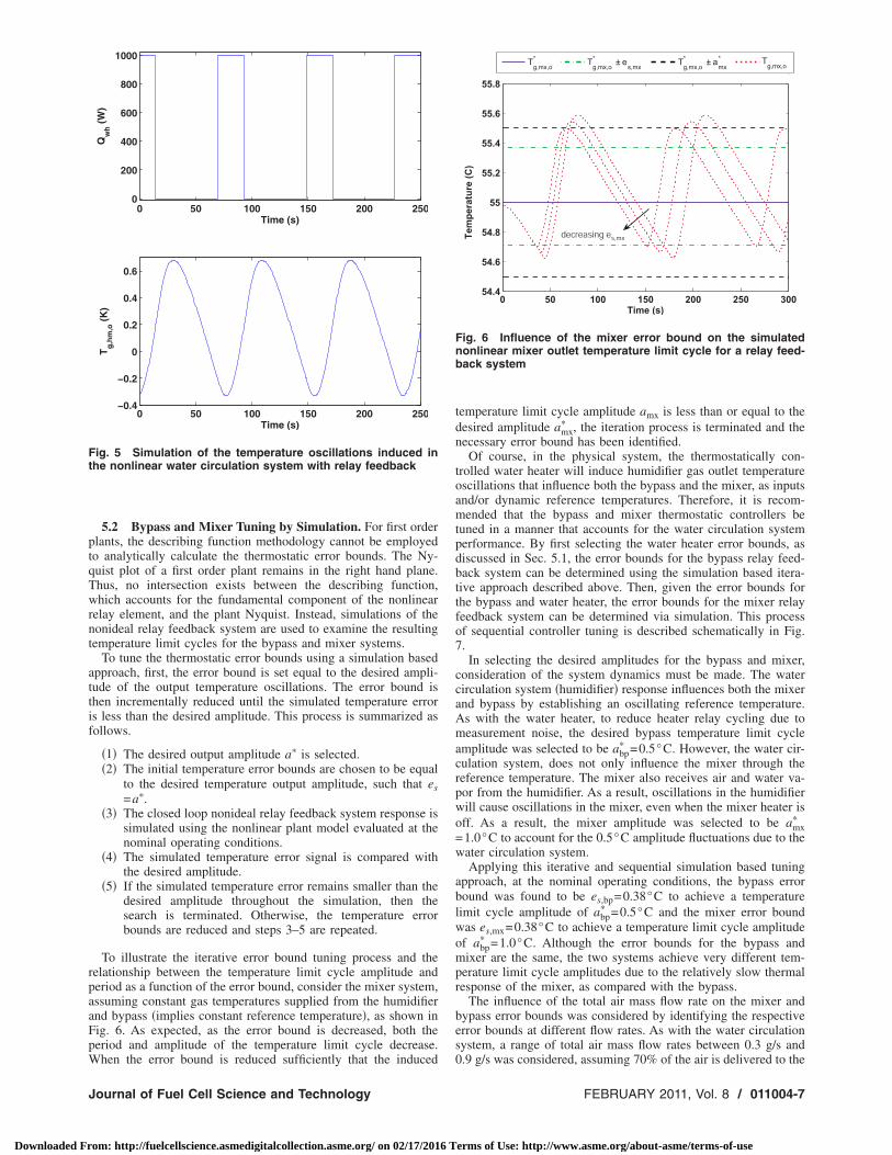
The ability of the describing function methodology to accu-rately estimate the temperature limit cycles was then evaluated bysimulating the relay feedback system applied to the nonlinear wa-ter circulation system model, as shown in Fig. 5. The nonlinearmodel was evaluated at the nominal conditions, from Table 2,with no changes in the reference temperature. Generally, the de-scribing function methodology resulted in the selection of errorbounds, which induce a reasonably expected humidifier air outlettemperature limit cycle period at the desired amplitude.
The induced humidifier air outlet temperature limit cycle oscil-lates with a period of 77 s, which is larger than the 58 s expected.However, the nonlinear system response oscillates between theforced u=�Qmax and the free response u=0 when the actuator isturned on and off, resulting in different dynamic response times.Starting at the minimum humidifier air outlet temperature, it takesapproximately 31 s to reach the maximum temperature, indicatingan oscillation period of 62 s if the free response time were equalto the forced response time. Due to system nonlinearities and thedifference between the free and forced dynamic plant responses,the temperature limit cycles are not symmetric about the referencevalue of �T�=0; however, the desired limit cycle amplitude isachieved.
Varying the air mass flow rate supplied to the humidifier be-tween Wa,hm,i=0.21–0.63 g /s �a total air mass flow rate range of0.3–0.9 g/s at rhm=0.7�, the required error bounds range from es�0.14–0.26°C to maintain the desired output amplitude of a�
=0.5°C. This change in air mass flow rate also changes the periodof oscillation ranging between 52 s and 74 s. In summary, the airmass flow rate does not significantly impact the necessary errorbounds and resulting frequency of oscillation, to motivate the use
of variable error bounds for the water circulation system.Transactions of the ASME
erms of Use: http://www.asme.org/about-asme/terms-of-use
ptqTwrnt
attif
rpaaFpW
Ft
J
Downloaded Fr
5.2 Bypass and Mixer Tuning by Simulation. For first orderlants, the describing function methodology cannot be employedo analytically calculate the thermostatic error bounds. The Ny-uist plot of a first order plant remains in the right hand plane.hus, no intersection exists between the describing function,hich accounts for the fundamental component of the nonlinear
elay element, and the plant Nyquist. Instead, simulations of theonideal relay feedback system are used to examine the resultingemperature limit cycles for the bypass and mixer systems.
To tune the thermostatic error bounds using a simulation basedpproach, first, the error bound is set equal to the desired ampli-ude of the output temperature oscillations. The error bound ishen incrementally reduced until the simulated temperature errors less than the desired amplitude. This process is summarized asollows.
�1� The desired output amplitude a� is selected.�2� The initial temperature error bounds are chosen to be equal
to the desired temperature output amplitude, such that es=a�.
�3� The closed loop nonideal relay feedback system response issimulated using the nonlinear plant model evaluated at thenominal operating conditions.
�4� The simulated temperature error signal is compared withthe desired amplitude.
�5� If the simulated temperature error remains smaller than thedesired amplitude throughout the simulation, then thesearch is terminated. Otherwise, the temperature errorbounds are reduced and steps 3–5 are repeated.
To illustrate the iterative error bound tuning process and theelationship between the temperature limit cycle amplitude anderiod as a function of the error bound, consider the mixer system,ssuming constant gas temperatures supplied from the humidifiernd bypass �implies constant reference temperature�, as shown inig. 6. As expected, as the error bound is decreased, both theeriod and amplitude of the temperature limit cycle decrease.
0 50 100 150 200 2500
200
400
600
800
1000
Time (s)
Qw
h(W
)
0 50 100 150 200 250−0.4
−0.2
0
0.2
0.4
0.6
Time (s)
Tg
,hm
,o(K
)
ig. 5 Simulation of the temperature oscillations induced inhe nonlinear water circulation system with relay feedback
hen the error bound is reduced sufficiently that the induced
ournal of Fuel Cell Science and Technology
om: http://fuelcellscience.asmedigitalcollection.asme.org/ on 02/17/2016 T
temperature limit cycle amplitude amx is less than or equal to thedesired amplitude amx
� , the iteration process is terminated and thenecessary error bound has been identified.
Of course, in the physical system, the thermostatically con-trolled water heater will induce humidifier gas outlet temperatureoscillations that influence both the bypass and the mixer, as inputsand/or dynamic reference temperatures. Therefore, it is recom-mended that the bypass and mixer thermostatic controllers betuned in a manner that accounts for the water circulation systemperformance. By first selecting the water heater error bounds, asdiscussed in Sec. 5.1, the error bounds for the bypass relay feed-back system can be determined using the simulation based itera-tive approach described above. Then, given the error bounds forthe bypass and water heater, the error bounds for the mixer relayfeedback system can be determined via simulation. This processof sequential controller tuning is described schematically in Fig.7.
In selecting the desired amplitudes for the bypass and mixer,consideration of the system dynamics must be made. The watercirculation system �humidifier� response influences both the mixerand bypass by establishing an oscillating reference temperature.As with the water heater, to reduce heater relay cycling due tomeasurement noise, the desired bypass temperature limit cycleamplitude was selected to be abp
� =0.5°C. However, the water cir-culation system, does not only influence the mixer through thereference temperature. The mixer also receives air and water va-por from the humidifier. As a result, oscillations in the humidifierwill cause oscillations in the mixer, even when the mixer heater isoff. As a result, the mixer amplitude was selected to be amx
�
=1.0°C to account for the 0.5°C amplitude fluctuations due to thewater circulation system.
Applying this iterative and sequential simulation based tuningapproach, at the nominal operating conditions, the bypass errorbound was found to be es,bp=0.38°C to achieve a temperaturelimit cycle amplitude of abp
� =0.5°C and the mixer error boundwas es,mx=0.38°C to achieve a temperature limit cycle amplitudeof abp
� =1.0°C. Although the error bounds for the bypass andmixer are the same, the two systems achieve very different tem-perature limit cycle amplitudes due to the relatively slow thermalresponse of the mixer, as compared with the bypass.
The influence of the total air mass flow rate on the mixer andbypass error bounds was considered by identifying the respectiveerror bounds at different flow rates. As with the water circulationsystem, a range of total air mass flow rates between 0.3 g/s and
0 50 100 150 200 250 30054.4
54.6
54.8
55
55.2
55.4
55.6
55.8
Temperature(C)
Time (s)
T*
g,mx,oT*
g,mx,o± e
s,mxT*
g,mx,o± a
*
mxTg,mx,o
decreasing es,mx
Fig. 6 Influence of the mixer error bound on the simulatednonlinear mixer outlet temperature limit cycle for a relay feed-back system
0.9 g/s was considered, assuming 70% of the air is delivered to the
FEBRUARY 2011, Vol. 8 / 011004-7
erms of Use: http://www.asme.org/about-asme/terms-of-use

htOwierprsvctc
6
swzttzpcdhqhc
wbstd
wc
0
Downloaded Fr
umidifier �rhm=0.7�. The bypass error bounds show little sensi-ivity to the air mass flow rate, ranging from es,bp=0.36–0.41°C.f course, if low relative humidity operation is desired, more airould be supplied to the bypass, resulting in a greater sensitivity
n the bypass error bounds. The mixer error bounds, however,xhibit a greater degree of sensitivity to the total air mass flowate, ranging from es,mx=0.14–0.65°C to achieve the desired tem-erature limit cycle amplitude of amx
� . As the total air mass flowate increases, the necessary mixer error bounds increase. Suchensitivity to the total air mass flow rate could motivate the use ofariable mixer error bounds. However, constant error boundsould still be used with the understanding that the desired ampli-ude will only be achieved at the total air mass flow rate that theontroller was tuned for.
Proportional Integral ControlThe thermostatic controllers, designed in Sec. 5, are inexpen-
ive to implement and are capable of regulating temperature toithin 1°C of the desired cathode inlet temperature. If, however,
ero steady-state temperature error is required or the limit cycleemperature oscillations are undesirable, a more sophisticated con-roller is needed. With the addition of controller integrator states,ero steady-state error to a step command in the reference tem-erature can be achieved. As a result, proportional integral �PI�ontrol was considered due to the simplicity of tuning with timeomain constraints and guarantee of zero steady-state error. Note,owever, that in contrast to thermostatic control, PI control re-uires the heater actuators to be capable of producing a variableeat transfer rate. Thus, there is a tradeoff between regulationapability and hardware and software complexity.
The PI controller is expressed in the frequency domain as
�Q = �kP,cv +kI,cv
s�e �16�
here the proportional and integral controller gains are denotedy kP,cv and kI,cv, respectively, for each control volume. By sub-titution into Eqs. �11� and �13�, the mixer and bypass closed loopransfer functions from the reference to the actual temperature isescribed by
�Tg,cv,o
�T�=
bo,cvkP,cv�s + kI,cv/kP,cv�s2 + �bo,cvkP,bp + pcv�s + bo,cvkI,bp
�17�
here pcv is the open loop pole location. The PI controller gains
Select WaterCirculation System
Limit CycleAmplitude
Find Error BoUsing DescrFunction An
Simulate BypasWater CirculaSystem Respo
Simulate FullHumidificatio
System Respon
Select InitialBypass Error
Bound
Select InitialMixer Error
Bound
if not within
if not within b
Fig. 7 Sequential process used to terror bounds
an be tuned upon inspection of the characteristic polynomial of
11004-8 / Vol. 8, FEBRUARY 2011
om: http://fuelcellscience.asmedigitalcollection.asme.org/ on 02/17/2016 T
this closed loop transfer function. For tuning the controller gains,two of the following three time domain constraints are selected:from �1� the proportional controller gain; �2� response time; and�3� the damping coefficient �overshoot�.
The mixer and bypass proportional gains are selected based onthe expected maximal actuator heater power �at steady-state overthe range of operating conditions� supplied Qdesign,cv for a speci-fied temperature error edesign,cv, such that
kP,cv =Qdesign,cv
edesign,cv�18�
Given an expected error of edesign,cv=1.0 K �corresponding toa�=0.5 K used for thermostatic controller tuning� and the maxi-mum steady-state heater power of Qdesign,bp=15 W andQdesign,mx=25 W, the proportional gains are kP,bp=15 W /K,kP,mx=25 W /K. For a critically damped response, the resultingintegral controller gains can then be calculated.
The closed loop transfer function from the desired humidifierair outlet temperature to the actual temperature is of the sixthorder; therefore, time domain design constraints �overshoot, set-tling time, etc.� cannot be used analytically to specify the control-ler gains. Instead, iterative pole placement was used to achieve adesired closed loop response. From inspection of the open loopwater circulation system poles and zeros, a stable slow pole islocated on the real axis at approximately s=−0.0008. This polecould be shifted or canceled by a carefully tuned PI controller.Because the humidifier water circulation system has an air flowinput disturbance and the model parameters were well identified, apole shifting controller was employed for improved input distur-bance rejection �16�. Using the linearized model of the water cir-culation system shown in Eq. �12�, the PI controller was tuned toachieve a fast response with less than 20% overshoot.
A summary of the final controller gains and resulting settlingtimes to a step in the reference temperature is shown in Table 5,along with the gain and phase margins. To prevent integratorwindup, a logic based case structure was employed, which enablesor disables the integrator while the actuator is saturated at Qcv�t�=0 or Qcv�t�=Qmax,cv.
7 Experimental Controller ComparisonThe closed loop thermostatic and PI controller experimental
responses, for a step in the cathode inlet reference temperaturefrom nominal conditions, is shown in Figs. 8–11. As expected, the
dgs
Check if HumidifierTemperature Response
is Within Bounds
d Is Bypass TemperatureError Less Than
Desired Amplitude?
Is Mixer TemperatureError Less Than
Desired Amplitude?
unds, reduce error bound
ds, reduce error bound
No
Yes
No
the bypass and mixer thermostatic
unibinlaysi
s antionnse
nse
bo
oun
une
system response with thermostatic feedback regulation results in
Transactions of the ASME
erms of Use: http://www.asme.org/about-asme/terms-of-use

te
tst
Fts
Frc
J
Downloaded Fr
emperature and humidity limit cycles, while PI feedback controlnables reference tracking with zero steady-state error.
Using thermostatic control, the desired humidifier air outletemperature limit cycle amplitude of awc
� =0.5°C was achieved,ee Fig. 8, as was the oscillation period. The time required toransition from the minimum to maximum humidifier air outlet
Table 5 Proportional-integral co
Heater kP,cv kI,cv
Bypass 15 3.25Mixer 25 0.22Water heater 263 1.60
0 100 200 300 400 500 600 700 8000
200
400
600
800
1000
Qhm(W)
Time (s)
0 100 200 300 400 500 600 700 800
55
56
57
58
59
Tg,hm,o(C)
Time (s)
PI
Thermostatic
Reference
ig. 8 Experimental humidifier air outlet closed loop tempera-ure response to a reference step, comparing PI and thermo-tatic control
0 100 200 300 400 500 600 700 8000
10
20
30
40
50
Qbp(W)
Time (s)
0 100 200 300 400 500 600 700 80054
55
56
57
58
59
60
Ta,bp,o(C)
Time (s)
PI
Thermostatic
Reference
ig. 9 Experimental bypass air outlet closed loop temperatureesponse to a reference step, comparing PI and thermostatic
ontrolournal of Fuel Cell Science and Technology
om: http://fuelcellscience.asmedigitalcollection.asme.org/ on 02/17/2016 T
limit cycle temperature is approximately 34 s, corresponding to a68 s oscillation period if the free and forced response times werethe same, agreeing with the simulation results. For the water cir-culation system PI controller, the resulting overshoot followingthe step in the reference temperature is larger than predicted insimulation, but still within the designed 20%.
ller gains and system response
tsettle�s�
GM�dB�
PM�deg�
9.4 142256 145176 20 138
0 100 200 300 400 500 600 700 8000
10
20
30
40
50
Qmx(W)
Time (s)
0 100 200 300 400 500 600 700 800
55
56
57
58
59
Tg,mx,o(C)
Time (s)
PI
Thermostatic
Reference
Fig. 10 Experimental mixer air outlet closed loop temperatureresponse to a reference step, comparing PI and thermostaticcontrol
0 100 200 300 400 500 600 700 8000
0.2
0.4
0.6
0.8
W(g/s)
Time (s)
0 100 200 300 400 500 600 700 8000.6
0.65
0.7
0.75
0.8
φg,mx,o
Time (s)
PI
Thermostatic
Reference
a
Total
Humidifier
Bypass
Fig. 11 Mixer gas outlet relative humidity response to a step inthe reference temperature, comparing PI and thermostatic
ntro
control
FEBRUARY 2011, Vol. 8 / 011004-9
erms of Use: http://www.asme.org/about-asme/terms-of-use

tFpstw
tFaTe
ftseaoNa
8
pcrta
Fb
0
Downloaded Fr
The experimental response of the closed loop bypass system tohis step in the reference cathode inlet air temperature is shown inig. 9, comparing thermostatic and PI controls. The resulting tem-erature limit cycle amplitude is approximately 0.5°C, as de-igned. Throughout the experiment, the PI controller is capable ofracking the dynamic reference humidifier air outlet temperatureith approximately zero steady-state error.The experimental response of the closed loop mixer system to
his step in the reference cathode inlet air temperature is shown inig. 10, comparing thermostatic and PI controls. The limit cyclemplitude was found to be slightly less than the designed 1°C.he mixer PI controller performed as expected throughout thexperiment.
The experimental mixer air outlet relative humidity responseor this temperature reference step is shown in Fig. 11. Becausehe actual mixer outlet temperature response is approximatelyinusoidal using thermostatic control, the relative humidity alsoxhibits an approximately sinusoidal response. Both in simulationnd in the experiment, the maximum excursion in the mixer airutlet relative humidity is approximately 10% for both controllers.ote that the mixer gas outlet relative humidity presented here is
n estimation based on physical measurements applying Eq. �7�.
PI Closed Loop Disturbance ResponseUsing the feedforward control of the air mass flow rate and
roportional integral control of the resistive heaters, anotherlosed loop experiment was conducted for changes in the systemeferences �cathode inlet temperature and relative humidity� andhe system disturbances �ambient temperature, total air mass flow,nd a reservoir fill event�. As expected, the PI controller results in
3800 4200 4600 5000 54000
200
400
600
800
1000
Qhm(W)
Time (s)
3800 4200 4600 5000 54000.2
0.4
0.6
0.8
Wa,hm,i(g/s)
Time (s)
3800 4200 4600 5000 5400
26
30
34
Tamb(C)
Time (s)
3800 4200 4600 5000 5400
60
62
64
Ta,hm,o(C)
Time (s)
measured
reference
Tamb
Wa
Reservoir Fill
φci*
ig. 12 Humidifier air outlet temperature response to distur-
ances using PI control11004-10 / Vol. 8, FEBRUARY 2011
om: http://fuelcellscience.asmedigitalcollection.asme.org/ on 02/17/2016 T
zero steady-state error. The overshoot and response time, follow-ing step changes in the reference temperature, is approximatelyequal to the response that the controller was tuned to achieve.
Figure 12 shows the humidifier air outlet temperature responseto disturbances. Interestingly, the cathode inlet reference tempera-ture step results in an increase in the air flow supplied to thehumidifier, causing an initial decrease in the humidifier air outlettemperature, which resembles a nonminimum phase response, butis actually due to the feedforward regulation of the air flow. Therapid 10°C increase in ambient temperature increased the humidi-fier air outlet temperature, requiring the humidifier heater powerto decrease to regulate the air temperature. A decrease in total airflow resulted in a decrease in the fraction air supplied to the hu-midifier, in turn, increasing the humidifier air outlet temperature.The reservoir fill event, which injects cold water into the reservoir,causes a dramatic decrease in the humidifier air outlet temperaturethat initially saturates the water heater. Finally, the decrease indesired cathode inlet relative humidity decreases the humidifier airflow, in turn, increasing the air outlet temperature.
The response of the bypass system to these disturbances isshown in Fig. 13. Again, the intent of the bypass controller is totrack the humidifier air outlet temperature. The bypass adequatelytracks the humidifier air outlet temperature excursions well, due tothe difference in closed loop response times of these two systems.There is an insignificant difference between the bypass and hu-midifier air outlet temperatures throughout the experiment.
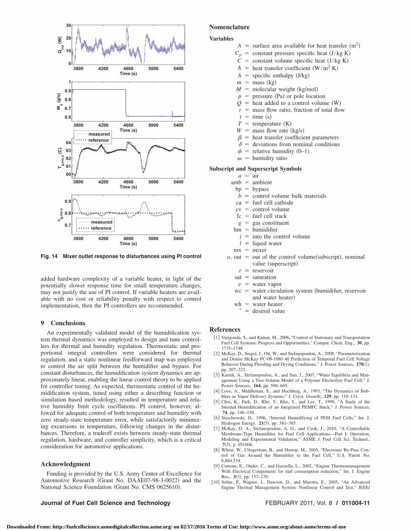
When the humidifier air outlet temperature initially decreases,following the increase in the cathode inlet temperature reference,the mixer heater turns off and then proceeds to track the humidi-fier air outlet temperature, as shown in Fig. 14. In general, theability of the mixer to track the humidifier is adequate. Addition-ally, the mixer outlet relative humidity is well regulated through-out the experiment. Although the relative humidity at the mixeroutlet was relatively well regulated with thermostatic control, thetemperature oscillations may not be desirable, depending upon theoperating conditions of the PEMFC stack to which the air is sup-plied. To eliminate these oscillations, the PI controller is recom-mended to guarantee zero steady-state temperature error. The
3800 4200 4600 5000 5400
0
5
10
15
Qbp(W)
Time (s)
3800 4200 4600 5000 54000.05
0.1
0.15
0.2
0.25
0.3
Wa,bp,i(g/s)
Time (s)
3800 4200 4600 5000 540059
60
61
62
63
64
Ta,bp,o(C)
Time (s)
measured
reference
Fig. 13 Bypass air outlet response to disturbances using PI
controlTransactions of the ASME
erms of Use: http://www.asme.org/about-asme/terms-of-use
apmai
9
tlprtcpfmstlzibrc
A
AN
F
J
Downloaded Fr
dded hardware complexity of a variable heater, in light of theotentially slower response time for small temperature changes,ay not justify the use of PI control. If variable heaters are avail-
ble with no cost or reliability penalty with respect to controlmplementation, then the PI controllers are recommended.
ConclusionsAn experimentally validated model of the humidification sys-
em thermal dynamics was employed to design and tune control-ers for thermal and humidity regulation. Thermostatic and pro-ortional integral controllers were considered for thermalegulation, and a static nonlinear feedforward map was employedo control the air split between the humidifier and bypass. Foronstant disturbances, the humidification system dynamics are ap-roximately linear, enabling the linear control theory to be appliedor controller tuning. As expected, thermostatic control of the hu-idification system, tuned using either a describing function or
imulation based methodology, resulted in temperature and rela-ive humidity limit cycle oscillations. PI control, however, al-owed for adequate control of both temperature and humidity withero steady-state temperature error, while satisfactorily minimiz-ng excursions in temperature, following changes in the distur-ances. Therefore, a tradeoff exists between steady-state thermalegulation, hardware, and controller simplicity, which is a criticalonsideration for automotive applications.
cknowledgmentFunding is provided by the U.S. Army Center of Excellence for
utomotive Research �Grant No. DAAE07-98-3-0022� and the
3800 4200 4600 5000 54000
10
20
30
Qmx(W)
Time (s)
3800 4200 4600 5000 5400
0.6
0.7
0.8
0.9
1
Wa(g/s)
Time (s)
3800 4200 4600 5000 5400
60
61
62
63
64
Tg,mx,o(C)
Time (s)
3800 4200 4600 5000 5400
0.7
0.8
0.9
φg,mx,o
Time (s)
measured
reference
measured
reference
ig. 14 Mixer outlet response to disturbances using PI control
ational Science Foundation �Grant No. CMS 0625610�.
ournal of Fuel Cell Science and Technology
om: http://fuelcellscience.asmedigitalcollection.asme.org/ on 02/17/2016 T
Nomenclature
VariablesA � surface area available for heat transfer �m2�
Cp � constant pressure specific heat �J /kg K�C � constant volume specific heat �J /kg K�� � heat transfer coefficient �W /m2 K�h � specific enthalpy �J/kg�m � mass �kg�M � molecular weight �kg/mol�p � pressure �Pa� or pole locationQ � heat added to a control volume �W�r � mass flow ratio, fraction of total flowt � time �s�
T � temperature �K�W � mass flow rate �kg/s�� � heat transfer coefficient parameters� � deviations from nominal conditions� � relative humidity �0–1�� � humidity ratio
Subscript and Superscript Symbolsa � air
amb � ambientbp � bypassb � control volume bulk materials
ca � fuel cell cathodecv � control volumefc � fuel cell stackg � gas constituent
hm � humidifieri � into the control volumel � liquid water
mx � mixero, out � out of the control volume�subscript�, nominal
value �superscript�r � reservoir
sat � saturationv � water vapor
wc � water circulation system �humidifier, reservoirand water heater�
wh � water heater� � desired value
References�1� Varigonda, S., and Kamat, M., 2006, “Control of Stationary and Transportation
Fuel Cell Systems: Progress and Opportunities,” Comput. Chem. Eng., 30, pp.1735–1748.
�2� McKay, D., Siegel, J., Ott, W., and Stefanopoulou, A., 2008, “Parameterizationand Denise McKay FC-09-1080 40 Prediction of Temporal Fuel Cell VoltageBehavior During Flooding and Drying Conditions,” J. Power Sources, 178�1�,pp. 207–222.
�3� Karnik, A., Stefanopoulou, A., and Sun, J., 2007, “Water Equilibria and Man-agement Using a Two-Volume Model of a Polymer Electrolyte Fuel Cell,” J.Power Sources, 164, pp. 590–605.
�4� Love, A., Middleman, S., and Hochberg, A., 1993, “The Dynamics of Bub-blers as Vapor Delivery Systems,” J. Cryst. Growth, 129, pp. 119–133.
�5� Choi, K., Park, D., Rho, Y., Kho, Y., and Lee, T., 1998, “A Study of theInternal Humidification of an Integrated PEMFC Stack,” J. Power Sources,74, pp. 146–150.
�6� Staschewski, D., 1996, “Internal Humidifying of PEM Fuel Cells,” Int. J.Hydrogen Energy, 21�5�, pp. 381–385.
�7� McKay, D. A., Stefanopoulou, A. G., and Cook, J., 2010, “A ControllableMembrane-Type Humidifier for Fuel Cell Applications—Part I: Operation,Modeling and Experimental Validation,” ASME J. Fuel Cell Sci. Technol.,7�5�, p. 051006.
�8� Wheat, W., Clingerman, B., and Hortop, M., 2005, “Electronic By-Pass Con-trol of Gas Around the Humidifier to the Fuel Cell,” U.S. Patent No.6,884,534.
�9� Cortona, E., Onder, C., and Guzzella, L., 2002, “Engine ThermomanagementWith Electrical Components for fuel consumption reduction,” Int. J. EngineRes., 3�3�, pp. 157–170.
�10� Setlur, P., Wagner, J., Dawson, D., and Marotta, E., 2005, “An Advanced
Engine Thermal Management System: Nonlinear Control and Test,” IEEE/FEBRUARY 2011, Vol. 8 / 011004-11
erms of Use: http://www.asme.org/about-asme/terms-of-use

0
Downloaded Fr
ASME Trans. Mechatron., 10�2�, pp. 210–220.�11� Ogata, K., 1998, System Dynamics, Prentice-Hall, Englewood Cliffs, NJ.�12� Khalil, H., 2002, Nonlinear Systems, Prentice-Hall, Englewood Cliffs, NJ.�13� Slotine, J.-J., and Li, W., 1991, Applied Nonlinear Control, Prentice-Hall,
Englewood Cliffs, NJ.�14� Hang, C., Astrom, K., and Wang, Q., 2002, “Relay Feedback Auto-Tuning of
11004-12 / Vol. 8, FEBRUARY 2011
om: http://fuelcellscience.asmedigitalcollection.asme.org/ on 02/17/2016 T
Process Controllers—A Tutorial Review,” J. Process Control, 12�1�, pp. 143–162.
�15� Taylor, J., 1999, “Describing Functions,” Electrical Engineering Encyclope-dia, Wiley, New York.
�16� Middleton, R., and Graebe, S., 1999, “Slow Stable Open-Loop Poles: To Can-cel or Not to Cancel,” Automatica, 35, pp. 877–886.
Transactions of the ASME
erms of Use: http://www.asme.org/about-asme/terms-of-use


![Controllable Sliding Bearings and Controllable Lubrication ... · Review Controllable Sliding Bearings and Controllable ... or evolutionary [5], but it does not change the fact that](https://img.dokumen.tips/doc/110x75/5fc50df11ca4e1756528a85b/controllable-sliding-bearings-and-controllable-lubrication-review-controllable.jpg)