Embed Size (px)
Citation preview

A Consensus on Powering and Grounding Sensitive Electronic Equipment
Thomas S. KeySandia National Laboratories
Albuquerque NM
François D. MartzloffNational Bureau of Standards
Gaithersburg MD
Reprinted, with permission, from Conference Record, IEEE IAS Annual Meeting, October 1986
Significance:
Part 6 – Textbooks, tutorials, and reviews
A paper presented to the IEEE Industry Applications Society Annual Meeting to support a proposal for
developing a new standard in the Color Book series, “Powering and Grounding Sensitive Electronic
Equipment,” Standards Project P1100.
The effort was successful and an active W orking was launched. The initial goal was to complete the
project in four years. Unfortunately, the issues were sufficiently complex and opinions diverse to the point
that the final “Emerald Book” IEEE Std™ 1100 was not completed until 1992, still a reasonable gestation
period by comparison to some other IEEE projects.
One of the lingering issues was to clearly define “sensitive electronics.” That ambiguity was resolved in
the 1999 update by dropping out the qualifier “sensitive.” It is also interesting to note that the 1999 update
of the existing 1992 book took seven years, compared to the six years it took to start from the vision (a
glimmer) described in this paper.

A CONSENSUS ON POWERING AND GROUNDING SENSITIVE ELECTRONIC EQUIPMENT
Thomas S. Key, Member IEEE Sandia National Laboratories
Albuquerque, NM 87185
Abstract-Aseensitiveileebariepmoessing systems proliferate in our facil i t ies s o do power-related pr&bms. Efforts to alleviate these problems have ranged fixm installing expensive power conditioning ~ - ~ a p p 1 r i n s s p e d a l g r a u d i n g ~ n ~ faund in mwtirral safe grwndhg practtoe Under- standing & what is actudlly going on has been lack- %. W e find eMmate power systems, modified from basic practice t o the extent of being unsafe, t h a t amtinue to be plagued with parering- and grounding- related prcblems. O u t af this chaos w e are persuaded to study Md understand the complexities of the pm- blem and to beain devela,inS mod practices. This is the drjective d;r the I E E ~ w&.&hg - ~ r o u p on Powering and Grcunding Sensitive FJ.dmnic Equipment, Stand- ards Project PUOO. we w i l l intmduci project p1100, preview its scope and technical content and, most hportantly, i d t e participation in th i s seriously needed consensus standard activity.
INTRODUCTION
Powering and gmmdhg sensitive electronic equipment is a growing concern for commercial and industrial power system designers. ThYs concern frequently matenalhes after start-up when electronic system begin^-* ""pinsf=~ow=- cadittning~mentormagicgmundYlgmethcdsisa OlmmanrPspanse. f n r w m a ~ t b i s c a r r s e h a s l e d t o unsafe pr- and vhlatk~ns of the Nationdl Elec- trical Code withAlt solving operating problems. hl- thmgh gmd teddcd information is available, there is presently no consensus on recommended practice. ~leawsraspcnsibkPnglneerstoproceedfrormvhat t h e ~ ~ ~ o v c r r c a n r e a d i l ~ obtain i n t h e l i t e r - atuie. ~lfozbnatdy, them 5s &nnicting information in the Uterature and, fo r most of us, the technical paxtkuka are w - a t f d g n to our power system design experience.
The amcept of load and source compatibility is not new. The need to prwide power with a steady voltage and fqpency has been recognized sin- the inception of t h e e lec t r i c u t i l i t y industry. However, t h e defiriition of 'steady1 has changed over the years, refZecting the greater susceptibility of increasingly saphisticated electronic equipment t o the departure
ktaady' anditionn Some of the early concerns were nicker of Wht bulbs due t o voltage variations and werheathg of elecbPmagnetic loads or h te r fe r - ence of? cmmmmhtion loads due to voltage waveform dhkdm. of these problems led t o the devekpment of valuntary standards w h i c h contributed significantly t o reducing occurrences.
Francois D. Wartzloff, Fellow IEEE National Bureau of Standards
Gaithersburg, MD 20899
M o r e reoently, txmsht vdtage disturbances associ- ated w i t h &at drarits, lightning, and power system mdt&hg hare emerged as a major anumrn to manufac- turers and users of electronic equipment. Today's c o m p ~ sbcut the quality of power are not easily resolved because they involve both a multitude of different causes and a variety of specific sensitiv- i t i e s in t h e affected equipment. Power system dedqners, uti l i ty companies, l w d as w e l l as source equipment manufacturers, must cooperate with each other t o find effective solutions. A s i n the past, voluntary consensus standards a re needed.
The issue of gmunling, in partioJlar how t o deal with noise and safety simultaneously, is complicated by cmflkhgphilosophies advocated by people of dif- ferent backgrounds. Power-oriented engineers and signal-oriented engineers often differ in thei r per- ce@m of cxrmmcn pxblem and solutions. One of the goals of the proposed standard is t o promote better und- of the real issues and t o dispel some mkmqhms cn how t o avoid or correct electronic system grounding problems.
Since the earliest days of electric power, users have aunt& an utilities to p m i d e electricity that is as free a s passible from outages, voltage surges, and harmrnlc waveshape dbtmths. Reducing such power line has always been a critical concern for utilities. Recently, however, new sources of
have begun to praliferate, just as many pieces of equipment a re becoming more sensitive t o these same power dktutmces. Sclne of these distur- banoea are generated by adjacent equipment, so that the utility supply ehnrld not be blamed far the occur- renoa These devalopments have presented utilities and users with a new set of complex power quality issues that w i l l require wide-reaching cooperative e f fo r t s t o be resolved.
A aammcnly applied solutIcn to power incompatibilities b to install interface equipment between t h e raw utility power and sensitive loads. Difficulties in assessing this need are: (1) the quantification of just hw mu& downtCme is powerrelated, (2) the sub- jective nature of estimating the cost of sensit ive bad misoperation attributable t o power. The cost/ benefit aspgts at the p e l e m can be addressed from the t d m h l point at view in a standard, but detail- ed economic analysis and specifir: dedsiars remain the prerogative of the user allocating t h e resources. Fozushg on the technical issues, dispelling miscon- e p t h s , and xemmmmm #xud practices can assist the user in making an informed economic decision.
W i t h that god M y defined, the new IEEE Working crrmp, Project Pll00, was fonwd to develg, a amsen- sus standard that recommends practices for powering md smurdins sensitive eleetrcnic loads in commercial Md h d u s t d l power systems. The document is cur rently a t t h e f i r s t d r a f t stage.
POWERING ELECTRONIC SYSTEMS
Powering an electronic system is fundamentally the oame as powering any dectrical sy6tem. Estimating the load, m a k M q aurrent and voltage requirements, or planning far l'izbm~ grPwth Lnrolvc9 the same basic i n f - ~ l l ~ ~ n . simil.arly, designing an appropriate alectrloal di6tribut.h system, selecting and coordin- ating overcurrent protection, and assuring good valtage z e q u h t h makes use of the same engineering practioes. Even the prindplea of availability and reliability can be applied to electronic loads in the same way a s t o any other load.
An excallent reference Ubraxy ava3lable for designing azmmercial and Mustrial power systems of a l l types is the m r Book series. There are currently nine Color Beaks in the Series providing recommended practioes. The objective is to assist in the design af &el reliab4 and economical electric power sys- tems by providing the consensus of knowledge and
of the centributing IEEE m e m b e r s . Project W O O is intended t o yield a new Color Book in the series, directed -y at powedng and ground- ing sensi t ive electronic equipment.
Computers are just like motors or lights: when the power goes away, the elecMQl device quits, and when power is restored, it restarts. Of course, it is fresuent3y integrity of the process rather than the actual device that w e must ourselves with. I f we lose power to m e high speed mveym being fed by another high speed conveyor, we can expect a mess samewhere m the factory floor. Likewise, a central proeesnn aartrdlling a check printer with a stack of ~ e n ~ a c a n m a n d s i n v a L a t i L e ~ w i l l m c 6 t ~ e l y be upset by t h e l o s s of power continuity.
Ihe duration of loss of parer continuity is the key factor i n pI.edicting if a process disruption w i l l ocarr. A large freezer may be able to a e through an axtage of severdl hwrs before caallng lass. We are aUowed seands to restore light in a hospital oper- ating roam. Oata pmcedng upset may occur in tens of mllllseconds, o r in cycles of 60 Hz ac ppwer. An artage Is therefore defined differently by differ- ent users and prpducera of electric power, somet imes creating an obstacle t o communication between these
parties. UtiUty COrmpMies and their paver supply ccntracts w i l l normally only address cutages measwad in mhtes. They do nut consider perturba- tions lasting a few seconds or less as the utilities resparsib-. When customer equipment is more cri- tical or mare sensitive than the nom. thev consider .it the cusbm?s prublem. The speciai POW& quality am3 ccntfnuity requirements af a number of commercial and industrial loads are described in the m E Oranse m Ill.
Data processing equipment susceptibility t o short auraUan (cydle to cycle) breaks i n power continuity shaild nat be wezgenerdlized. First, a computer can ride thmugh a shart aRage. It happens every cycle of the ac power sinewave. Secatd, ampubs &a.U be M more sensitive to steady-state voltage variations than any ather load. American NationdL Standard C84.l establishes steady-state voltage ranges that apply t o
&ll equipment. Furthermore, harmonic dktorcion in the utLUty voltage has not been &own t o have any more impact on electronic loads than on motors o r relays. We conclude that if electronic loads have arscegtibilkk to power-lIna disturbances, they also have tplerancrs that may reduce the cost and effort required t o protect them.
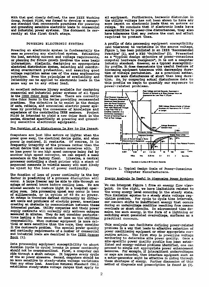
A pndile of data prooessing equipment susceptibility (and tnleranca) to variations in the source voltage, Pigure l, has been prblLshed in an IEEE 'Recommended Practice1 [I], and a NBS IGuidme' [Z ] . Presented as a "Typical dedgn objective of power-conscious computer hardware designersn, it is not a computer industry standad However, ae a typical susceptibil- i t y profile, it does denmskah the useful feature of increahing ~~ trrlerance w i t h decreasing dura- tim of voltage pertubation. As a practical matter, there are mom d short than long dura- tion. So, by comparing actual disturbance data t o this profile we bagin t o quantify our exposure t o power-related problems.
S..l w r . r r h*.,
*w.h.*k.r. -r+..Plor.w* 1 aCK*
Cahcmaml.*. S m m f - n '
Figure 1. Typiedl Design Goals of Power-Conscious Computer Manufacturers.
sis Is Draanoslna Power F m b l e m s
'we can interpret Figure 1 f r o m an eneryy flow view- :point. On the right, w e have limitations related t o the vrcng energy level oasr rhg b the steady state. T%.~s lhhth equates to a M y state voltage reg- ulatiar problem. For cycle t o cycle time intervals, cur a~naern shifts to insufficient energy that occurs during an undervalbge ocnditicn resulting fmm oDrmmon overloads or short drrxlita I n microsecond time do- mains, too mu& energy, fn the form of a Lightning or s i k & h g event genefilted overvoltage, surfaces as a pract ical concern.
This analysis can fadl i ta te defining power-related p ~ l e m s in a way that leads to effective selection of power c m d k h h g equipment ar ather appropriate cor- &ve action. The f i r s t step is powerline voltage 'mcnLtoring t o determine s i te power quality. Once a site-specific power quality profile has been estab- lished and enemy-related ~xblems identified. one can prnoeed to out app;opriate power enhancement - For example, if intermittent undervoltaqes or sqs are LPCorded, then interfaae equipmerrt such-as a motorgenerator might be effective in riding through these shorhges af energy. Further discussion of this method of aiagnds and prescription is found in [3].
The application of Ffgure 1 seans quite s t r a igh t - fccwamlt however, solving a real-llfe power-related pxcbbm may n& be. For one thing, the tolerance t o overvoltage of severdl hundred volts, indicated in Pigurn 1, asllumes an W a u l t a t t h a input t o the computer p a r supply. The electronic equipment tolerance t o overvoltages experienced in o the r locations may be s ignif iant ly less. Noise coupled into the electrrnic system via many possible alternate paths,ascomparedtosurgesanductedalcngthepower line, can d i s r u p t data a t a 5-volt logic level.
Related to the noise-coupling problem, is the attemp to apply Pigum 1 in the presence of pax gmunding or incorrect surge protecting of equipment. These mistakes llay dllow irrternally generated power-related problems tha t to ta l ly evade any power in te r face equipment installed, per Figure 1, t o protect the d t e from the outside world. A t the same time, such interface eqiprment w i l l be adding cost and probably reducing overal l power system rel iabi l i ty .
A ~ ~ e n g i n e e r i n g a g ~ ~ ~ r e q u i r e d ~ ~ ~ l ~ address all aspects of the power- and noise-Mated: pmblms. In Pmje~A PllW, we axe attempting t o pre- sent the best explanation possible of the myriad of power enhanoanent products and at the same d m e main- tain a systems perspective. This perspective must include &her critical elements of the power system, Le. gmunding and surge protection details, and in- stdllaticPl procedures. We have faund that grounding, afscussed next, is a key to noiserelated problems.
GROUNDING ELECTRONIC SYSTEMS
I h e a t b j e c t o f ~ i s p e r h a p s t h e m D s t m i s u n d e r - stood, w i t h the result that a large portion of t h e p p l e m s in power s u m y applkatims ori- glnate from inappropriate grounding practices. An indication of the complexity of this subject is the fact t h a t it occupies over five pages of t h e IEEE dictionary; no wonder misconceptions s t i l l abound. The existence of this ~ r ~ b l e m in electsonic svstoms can be srplained by t h i different meanings a&uted t o the term 'qmnd ' by the d i f fe ren t spec ia l i s t s involved ~ta&q w i t h -the 60 Hz or powerzfrequency engineer, 'ground1 is syncmymous with 'earth'; its functbn Ss to prwide a lcu-impeianca path far return & power system fault Currents to the generator. This low-impedance path serves a safety role by limiting valtage differenae& during kystem faults aod by allow- ing sufficient fault currents t o assure prompt trip- ping of t he source c i r c u i t breakers.
In this context, ground co~lllections a r e generally large copper conductors, offering low impedance to pa~erfrequency current. Emphasis is given to the ~ Q B of the connection t o 'earth1--that is, t h e subjamat d - b y apprc~riate dimensions and number of Mven rods in the earth, of buried counter-poise conductors, etc. The eafety grounding system is passive and shaild n& be called upon t o carry rated aJrrPnt ex- during intermittent anomalies of power system operation such as short circuits. Occasion- ally, steady-state currents may be present due t o device Leakage o r t o the nearby influence of strong magnetic fields, for instance adjacent w n d u d o n of an arc f'urr~aoe Nevertheless, the steady-state cur- rent in grounding conductors should be re la t ively small when compared to phase onductor currents (NEC 250-21).
wE and %eferencinu" Must Be Consid~reQ.
Shirring now to the electrrnic engineer, designing his data praassing equipment, 'ground' is synonymous to
'chassis1. That is, t h e metal enclosure of t h e equipment, ea&3mes symbdLtcally concentrated into a aingle shiny metal pad a t the bottom of the cabinet, to whim all anne&cm to 'ground* are routed--and n& always by t h e most direct route. H i s data pro- cessing circuitry Involves analog or pulse voltage signals of generally less than 15 volts, o r it invol- ves cur ren t loops of a few milliamperes.
These signdls can be transferred in a balanced, un- gruutded dm& or a single-ended drcuit wW a com- mcn reference. Balanced circuits are isolated from graud but their vdltage wfth rssped t o ground (com- mon mode) is still significant t o the operation and potential susceptibility of the circuits. Single-' ended circuits carry signals referred t o a common patential, most often tha t of the equipment internal chassis, generally called 'reference'. Thus, i n either case it appears that the electrcllic engineer's concern is that his referencing system carries signal currents that can beaDme pdUuted by spurious ground currents either through common connection points with t h e earthed system o r by common-mode noise coupling.
Nau entem the systems engineer responsible for the hsWbth cd the dorta processing system within one room cd a lmildhg at best, or distributed among sev- eral buildings at worst: to him, 'ground' t a k e s a d a l e meaning. Tha first is the cacept of the power system engineer, the second is the concept of t h e d t d x d ~ = engineer and, alas, they are not the same. If only the f i r s t had been called 'earth', and the d call& t r e f ~ l , &s the designers would have cocodinated their two distinctive requirements ahead af time and much cm-site misery w a i l d have been avoided.
Instead, in the electronics engineer's case, t h e im- pedance of his 'reference' system includes a substan- tial inductive compcnent because of the high frequency a€ the signal and noise axrents. The large existing oqper cables, dtable for earthing, are not suitable far referwdng. A new gmund referwoe grid pmviding a large number of different path Links for the various noise frequencies w i l l now have t o be incorporated in to t h e system.
So we see, for electronic loads, w e have both safety and n a b to cmcern oursalves with. Safe operation a5 an elazh-hl ar electronic system depends on the fntegrity and law impedance of its mrthinq. Undis- tmbd c p r a t h of the same systems depends on the g m m law impedanoe of its eferen regardless 0fF-e between the refLence 9 t h e ea r th 121.
The significance of reference and insignificance of earth wmeckh can be illustrated by two examples: t o prove its reality, consider t h a t sophisticated equpent aboard an electronic countermeasures air- phie are doing quite well, thank you, without an earth mecticn; back m the grcund we find an fflu- sfm held by th2? s y a Cperaeor, confronted with in- terferenoe and a refmcinq pdlem, when he contem- plates and scPnaimes implements 'better grounding1 by breaking up the ccncrete flax a€ the omputer room t o i n s t a l l additional ground rods.
The salutim to this cperatnPs problem is not 'better groundhg', but better referencing--such a s in the
uf the airborne electrcnic: system. On the ground level, the better referencing can be obtained by sstabllshfng a 'gmund grid'. Here the major cri ter- h is lw imwdance at h h h frecruencie~ between any two paints of the gmamd grid. Recall that the safety gnxurd system shaild pmvide low impeaanCe a t low fre- quencier In a computer room design, the 2lx2' grid
3

(d a usual raised floor structure lends iW quite natumlly to prrnriding such a good reference. There are of course a few electrical design features that aust be prqm3y fncmpcaatsd References [2] and [4] already pmvide guidMce for hplementing this sdu- tjm, and Pruject P l l O O w i l l extend the guidance to t he s ta tus of a consensus standard. . . .
4 at Noise or Sume C-ould Nut Create -. Ihe first dde affect is associated with the problem c& dnxlathg aurents in the ground and reference arductoas. W W 1 c u t question, these currents can in- ject parasitic aFgnals into the data lines. This in- jecdm k --mode noise q l i n g caused by una- Midable rhsred m e e t i o n points between the power system gmYd and the dlectronic equipment chassis. The problem is real, the side effect is associated with how not t o solve it.
lhere have been a number & apparenfly rem- edies a& as so&5mes by opening up these P.cund loops', by creating a 'single point ground', by estabLLshing a 'dedicated/isOlated graund', and finally, in the ultimate language contradiction, by hs!aUy a ~ f l c d n g ground'. All of these mncepts, d v a t e d by steady-state, low-level noise reduction thecny, can and f m p e n t l y do werlook the potential of power frequency faults.
Attempts t o decouple equipment chassis from earth ground for the purpose of isolating and insulating often defeat t he basic safety function of earth gmmd. !lWq ignora safety and hardware damage issues associated with the relatively rare but potentially lethal &tuatIons bccurring during power system faults and Ughtnhg surges. They also violate the National Electric Code as described i n 151; such practices should be eradicated!
C o n t i n u i t y of the green wire or metallic raceway gm.mdhg system is not incompatible w i t h achieving effecthe ~~~ Simply apply the principles of the gmurd reference grid discussed abwe and in m. Give careful attention to surge pratecllon for M data and p e r &es as presented below. Don't resoattotamPeringwithsafetyaspectscUthegmund- h g system to cartml nakse. Finally, as a consulting engineer, called upon to correct power- o r noise- rdated problems, beware of both the desire for and the existence of dangerous grounding practices.
Another adverse side effect is assmhted w i t h t h e anfiguratLrr and use cb qmmdhg conductors. It is the &aurmw and acnv& at h a t is callad 'corn- non mroda* and 'differential modef in multi-conductor .ystems I n k i d l y defined in the context of commun- icationa draritry, these two modes have been applied to ac power systems that include phase, neutrirl, and graudinJ amdwkxs Here a grcunding CEnductor ex- ists or its hpUm3 by the presence of earthed bodies. As with ' r e f m d n g ' , the situation is confused by the blurring of lxundarles between signal processing kduxilogy and pawer dellvery/system safety require- ments.
D- on mfxr in eo~dmon mode but aures might be erzmeatnty pprqMsed that address cmly differential mode dkubame, or vice versa. Remedies t o a dif- fersdhl-mode surge can Q.eate a anman-mode dism%- an- For instanoe, a fresuenly applied and very ef- fective memod for common-mode noise elimination is the lnstallaticn of an lsohtbn transformer. However, we should not expect this transformer t o reliably attenuate differential-mode noise (63. Conversely, the installatlcn of a single protective device between
the phase and neutral caductaw, at the end of a long bran*' circuit, w U k (1) clamp the voltage betwaa? thge two onductcas, and (2) create a large vdbge, ddntoanum~1made,betweenthaneutrdlMdgmunding conductors.
The appmpriate solution, discussed in detail in Re- fer- m for the c a m of a single-phase three-wire wstem, consists of providing an additional surge- &mpiG device betwe& the nejrbal and grcunding &- ductas. Project PllOO w i l l address the polyphase as well a s the- single-phase situation.
With fonethmght, these side effects can be avoided. It 16 f&le to design a syetear whem noise problems are a ~ e y &ved withaut resorting to unsafe gmunding practkmd We have pointed cut that a re- ference grid system may k economically incorporated in a camprter room raised floor. Reference [4] des- cxibes how the reference grid app- uhm used with cumputer power centers (isolation transformers) and surge arppregLll nawca)rs can o y harmonize power and signal gzuu&ng requirements In Reference M detaLled guidelines are pmvided for computer room gmmdhg. Hawever, sinsince these dauments do nat am- stiM;e a mnsensus standard, one major goal of Pro- j e a P l l O o ~ b e t o ~ a c r n s e n s u s o p i n i o n by descxibing gocd praaices as wedl as by citing erron- eous practices t ha t should be avoided.
SURGE PROTECTION
POW= SySkDS aZ8 exposed i n f l u ~ c e ~ Which can 0oclpl.e en- into the drcuits, .causing a momen- tary ovenrdhge or wercurrent, generally described by the term 'surge'. Internal switching of loads in these systems can also cmab these momentary events. Another phenomenon, the discharge of electrostatic charges that have built-up on t h e human body or objects, can also inject unwanted voltages or currents
ekchcmic circuits. Finally, another threat is related t o nuclear explosions effects, under the aczonym of NEHP (Nuclear -etic Pulse). The prcpmed standard w i l l address the first two of these surges, lightning- and switching-related surges.
Suges can have many effects on equipment, ranging hprm no detectable &ect to ampplete destruction. In g e n d devices witlistand increas- ing valtage suqes amtil dieladric breakdown occurs, while electrcnFc devices on have their operation up- set befcue hard failure - W i t h increasing surge levels, p-.vvely mom inbmse upset oocurs, until breakdawn takes place. I£ sensitive electronic data prPcesdng equipment shculd be pmtected from even the upsetting levels, it is &made that damaging surges need to be dealt wi th before they prcpagate beycnd the service entry .for t he computer room 171 and [El.
Definittcas of the level beyad which transient aver- voltages bwnne a Uuaat depend an the type of victim esuSpment or praPsn Where electrosPechanicdl devices can generally tolerate short duration voltages of t w i m rating plus 1000 volts, few solid-state devices can tolerate more than twice their normal rating. Furthermare, data pmxssing can be affected by fast changes with relatively small voltage amplitudes compared to the hardware-damaging overvoltages.
tninq Sumes Can Strike in More Wavs Than One.
Lightning surge cn-power systms a;r;ur in two modes: direct attachmsnt of the lightning path t o the power systems anductors, and electromagnetic coupling of energy krto the pwer system conductors by the radia- tion of a nearby lighting discharge.
~ h c t clttacfiment L r j d the total lightning current Lrto the sy- The ammt m d e a range from a few thousand amperes to more than 200,000 amperes. Howevartthexap3dctrarrgeofcurrenttA?xqhtheimpe- dance of the aarducbm prcduom a high voltwet m o s t oftenthishiqhvdltage~useseawndary flashoverto gmund, divarting ecwe currtmt even 5n the absence of an fntentlcndl divezter. A s a a, equlpments con- nected at the end of overhead conductors are rarely exposed to the full lightning discharge current.
Muaionofsurgesbyneazby~Mningdischargeisa less dramat& but mom f rqmk event ' The resulting surge dma&d&h are influenced not only by the driving fareP-.the e J l p e t i c field--but also by theresparseafthepwersy~ftsnab.ualoscilla- t . Thh dual origin makes a general description cP the @meti&& but neveztheless a con- sensus & an what representathe threats can be expected in various physical environments (91.
Wheneve a drolft contafning Qpadtanea and induct- ance b being switrhed on or &, a transient disturb- ance - because the aurents and vdltages do not ma& hhntangusly their final value. This type of dbtwimm Js ininescapable and b severity depends on the d a t i v e pover level of the load being switched compared to the power system in which the switching takes plaoe. Most of these disturbances involve the respense of the paver system, just as in the case of induced lightning surges, so that in practice t h e suqes &senred w i t h i n a building are similar in their diversity, regardless of their origin--lightning or switching.
M o r e aanplex drcutt phenomena, such as current chop- ping and restrikes, can praduce Eange voltages reach- ing ten times the normal drcuit voltages, involving en- levels determined by the power rating of the elements being switched. These complex surges can have very destructive effects, wen on rugged equip- ment, and must generally be controlled a t the source rather than simply mitigated a t t h e load [93.
Effective h.oteetixr Teduhues Have Been Dwelmecj.
S w i v a l o r ~ ~ a E t h e e q U i P m w t can be a d a k d in thtee manners: eliminating the cause ab surges (for instance, eliminate lightning, switch- ing, d), producing eqdpmerrt immune to any level of avges, no matter how high, or, the obvious choice, finding the best economic trade-off where moderate avge withatand capability t built into equipment, and the worst suxges ocFurring in the environment are duced, by application of suitable pmtective devi- ces, t o a level which the equipment can tolerate.
Because the sau~e ofthe suge is an energy transfer phenamencn, involving a any attempt a t block- ing or - this current by a high impedance series path w i l l only produce higher surge voltages untjl breakdown ocx;unr Breakdown allows current in an unoartrdlled manner, generally through an unwanted path. In contrast, a surge protective device, by diverting the offer6 a ]arm, predictable and therefore harmless path.
'Ibis d ivedm d majar w e currents is best accom- plished in t w o stages The f i r s t diversion should be pafarmed at the entrance t o the building, typically by a mnrentCDndL fauye arrebte, such a s a sparkover type device, rated for t h i s duty [lo]. Then, any residual wervdltase. h P m the action of the
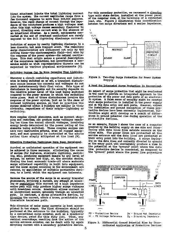
Forthisseor~my~' ' , we mxmmend a type adid .tb. da-stalled a t the power panel af the armplter rwm, at the terminals of a connected load, etc. Figure 2 illustrates t h i s coordination between two surge diverters and a series impedance.
A Need for Sdme -ion Is Re-.
An aspect of m.uge pxtedm that might be overlooked is the need to p m d e an integrated approach to the p- oP the power and data ports o£ an electron- ksystem. Afakeenseofsecwkymightbec~ted when surge p n b z t h is installed in the paver supply and at the data entry and exit ports. However, unless the h s W b t h and ground c o n n d c m of these pro- tective devices have been oxrectly implemented, dif - -ties might s t i U develop as a result of differ- ences in gmund - rise during operation of the protective devices.
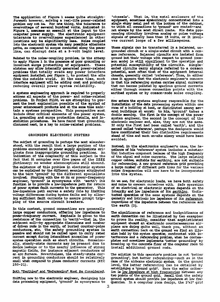
As an exaqL+ Figure 3 shows the case of a computer powerrd by the krilding supply cn one side and inter- facing with data lines from cutside sensors on the other aide. The power lines are protected a t the service entrance and the data lines are protected a t their entry point into the bullding. A surye imping- h g on the data Unes and corredly diverted t o ground at the entry paint w i l l unsvddably produce a rise in the potential a t the 'ground' point where the data line p-ve device is connected, as compared t o the *groundt point where the power Line pratective
$2 $5 :x<> ,
COMPUTER rr POWE@ 7' .+- : ry & 0 n - I- DATG
- - -
PD - Protective Device Zm - Ground flat Impedance Vr - PD Voltage Reference Zg - Grounding Impedance
FiPure 3. Differential G r a u d pchn th l Rise bv Unco- m i c e entrance akedxs, can-be dealt w i t h by again - diverting current w i t h a seccndary protective device. oniinated ~pp- af protective bevices
5

d w b is &md. The same difference of poten- tials w m l d adse it the surge impinged on the parer supply port. Thus, the 8ground1 patentiah on the power and data kRerfaoe inputs at the computer cab- inet viU not be t h e same, leading t o upse t s o r damaga %his phenwiendn is frequently t o the dismay af the user who thar.ght that adequate prutection bad been implemented w i t h the two devices iwtalled at the en t ry points.
In such an instance where the entry points are f a r apart, the s d u t h cDnsists in providing a secondary prct6ztive device fa r e.a& port af entzy into the w m - puter -in& (or entry b t h e ampter roaap where the computer is installed on an equipotential plane o r gmund refereme grid), and assuring the same point of (graud' arm& 16 used for these protective de- vices. Hhile the qualitative aspect of t h i s solution is gaining recognition, the quantitative parameters still need to be investigated. By the time Project PllOO nerrrs ~ r p p p l e t i n q we expect tha t measurements, now in PIUJ- at the National Bureau of Standards, w i l l contr ibute t o the quant i ta t ive answer.
We have thus far review& the need and some of the key issues that m c * i . us to recommended practices for pow& and grrunding d t i v e e l a loads. In so doing we recogniK that there are -y many more details t o address and many opinions and f a c t s t o remncile. The following section w i l l layout how we are current ly proceeding i n this effort . It is intended that enaqh detail BE provided t o encourage discussion and feedback t o the Working Group.
a DDr OV ed SC 0 D@ and P U ~ O S ~ of Pl loQ
Project P1100 is titled nRecomraended Practice f o r Pawering and Gmundlrag Sensitive Electronic Equipment (A Color Beak)* The IEEE technical sponsor is the Power Systems Engbeehg committee of the Industrial Appllcatims Society. A scope has been approved as follows:
*This project recommends design, ins ta l la t ion and practioPs for elecfrrcal p e r and ground-
ing (including - safety and noise control) of sen- sltive eledxmc lm3.s such a s computers, industrial controllers, and other electronic da ta processing eqdpment used in oDmnaercial and industrial applica- tions.'
The stanQrds prq/ect request (PAR) w a s submitted i n June 1985 and approved by t h e IEEE Standatds Board in September. A 'strawmanl a t l i n e for elevem cfiapters was developed and chapter objec- tives translated into a set of directives to chapter rnrthora Internal and extend rwiew procedures have been established. Preparation of a f i r s t d r a f t is underway.
Meanwhile interest continues ta grow. A number of trxtondls have been dfered bd31 inside and outside of IEEE. As an apparent offshoat of deregulation, the utility industry is beginning t o look a t markefing a higher qual i ty e lec t r i c service with power conditioning equipment incorporated a t increased electric energy rates. Still, there is no consensus standard available a s a reference f o r e lec t r i ca l engineers responsible for t h e power system design. Help is needed in developing, writing, and reviewing
lMROlXJCTION - mers the pupcse and backgruuna in much the same way as in t h i s paper.
SCOPE - a s quoted i n t h i s paper.
DEFINITI.CHS - thk daapter provides definitions not atherwise available in IEEE Standards o r a s necessary t o improve readability. The Chapter Qlairperscn is mPmvost Marshalu with regard t o use of undefined terms or acronyms i n other chapters.
~ N E E D ~ D E L I N E S - t h i s c f i a p t e r i s i n t e n d - ed to identify the relevant codes and standards as w e l l as the existing electrical environment that sensitive electronic equipment is typically subjedd b in the field. Topics include coor- dinatim w i t h other guidelines, electrical safe- ty, - quality, grounding, surge protection, Ufe-safety, and telscommunicatien systems consi- deraticns. These guidelines are established a s a basis for the treatment of performance require- aPents and recommended practices in subsequent chapters.
FWfWElWMS - this chapter trtroduces the reader to the fundamental technical information neces- mxy to understand and to apply ~ ~ ~ ~ m m e n d e d p r a c tices for dedgn af a compatible and essentially hazan3-free interconnection. Fundamentals not unique to sensitive electronic and/or electrical equipment will be treated very lightly, o r only by reference t o other IEEE Standards and appro- priate books on recommended engineering prac- ttm. Fundamentdls t o be covered include power system quality, !2hmnic data processing equip- ment power qualxty requirements, load and supply annpatibi?ity, grounding bonding and shielding, protection, and wiring practices.
REa3KMWDED DESIGN/DISTWATION PRACTICES - k the main message of t h i s publicatim and is ex- pected to be most difficult t o gain consensus. Vagueness at this point wculd be a disservice t o the reader. We intend to .put down on paper our d d v e enqineering e . c e and judgment to pinpoint recommended pra-ces. The proposed subjects are general discussion on performance and safety, 60 Hz ac systems, 400-480 Hz systems, and Ufe-safety system interfaces and controls.
KXS-REam4mDED DEs IqSTWATxaN F'RACPICES - is the chapter in which we very daliberately a#ack "wives8 talesn and raise 'warning flags," but are careful nct to h t r d u c e any new mncepts or materials Comnwolly abSezYBd mn-~mmended practices w i l l be emphasized. The chapter is aRllned by specific design topic to facilitate quick re t r i eva l from t h e reference.
SPECIAC MEASVRENENTS AND INSTRUMENTATION - presents information on specia l measurement req[l-ts and on available equipment that are unique to investigating and diagnosing problems in power systems that serve sensitive electronic equipment. The proposed approach is t o start w i t h dc mehsurements of voltage, current, and power and to progress through the fundamental frequencies (60 and 415 Hz) t o harmonic and higher frequencies, up to 300 kHz. RFI/EMI wiU be covered by reference only.
- - t h i s standard. the technical infomatim base established in the
6
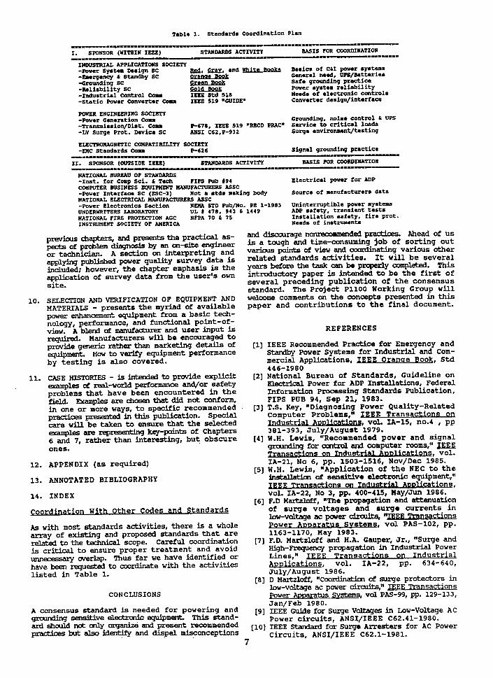
T a l e 1. Standards Coordination Plan
INWSTRIAL APPLICATIONS SOCIETY --er system Design sc m, and lIhits Basics of Ccf power sptamr - w r g m c y & St~ndhy sc QmmLEWi General need, ilPiC/&ttuiu -Grounding SC E U s L B Q k Safe g r d i n g practice -Reliability SC Pwer system r e l i a b i l i t y -Industrial Control C o n Needs of electronic controls -Static Power Converter C o u IECE 519 %UIDE* Converter design/interface
POWER ENGINEERING SOCIETY -Pov.r Generation C o u Grounding, noise control b UPS -Tranwission/Dist. cou -78, IEEE 519 .Z?.CD PRACn S u v i c e t o c r i t i c a l loads -LV Surge Prot. Device SC ANSI C62,P-932 Surge e n v L r o ~ ~ ~ t / t e s t i n g
EISLTR(IRUGLlET1C COMPATIBILITY SOCIETY - U C Standards Cam P-626 Signal grounding practice
N.DIIIYI...MIU-II - UPIOI-
11. SPONSOR (OUTSIDE IEEE) ST- AffLVITY BASIS FOR COORDXUATION -I=----= ---- YUIIIPlUIUU
NATIONAL BURUU OF Sl'AW0ARD.S -1nst. for Cow Sci . & Tech ?IPS pub I94 d l e c t r i u l power for ADP CfflFVTER BUSINESS WIF?fEXT MWUFACNRERS W S C -Power Interface SC (LSC-3) Not a s t d s making body Source of nanufacturerr data NATIONAL ELECTRICAL IUHUFAClURERS ASSC -Power Electronic6 Section NEnA STD Pub/No. PE 1-1983 Uninterntptble pawr sySta.s UNDERWRITERS LABORATORY UL 1 478. 943 b 1449 ADP safety, transient t e s t s NATIONAL PLRE PROTECTION AGC NFPA 70 L 75 Installation safety, f i r e prot. INSTRUMEWI' SOCIETY OF MIRICA Naeds of hutrumants
pm- apters, and p- practical as- and di5m-e nQveOOmmended P- Ahead of u s - p - a wogis by a engineer k5 a tough and the -co~s~ae ing job of sor t ing out or technician. A section on interpreting and various PO- of view b a t i n g various other applying pubushed power q u a y survey data related standards activities. It w i l l be several included; however, the chapter emphasis is the Y m befm the task be ~ r q ~ e r l y -. This appWtFon of survey data from the user% own i n t d u c b ~ Paper k intended t o be t h e f i r s t of s i t e . several preceding publication of t h e consensus
standard. The Project PllOO Working Group w i l l 10. SELECTION AND VERIFICATION O F EQUIPMENT AND t+elamW ~0lUmelIt .S on the C O n ~ p t s presented in this
MATERIALS - presents the myriad of available paper and contributions t o the f ina l document. power enhancement equipment from a basic tech- nology, performance, and functional point-of- view. A bbmd of mufaehrrer and user input is REFERENCES required. Manufacturers w i l l be encouraged t o prwide generic rather than marketing details of [l] IEEE Recommended Prac t i ce fo r Emergency and equipment HOW tn verify equipment performance Standby Power Systems for Industrial and Com- by t e s t ing is also covered. mercial Applications, D a e Book, Std
446-1980 11. CASE HlSrOKIES - is intended to provide explicit [2] National Bureau of Standards, Guideline on
examples cb redl-world per£ormance and/or safety E k d r b l Power for ADP Installations, Federal problems t h a t have been encountered in t h e Infornation Processing Standards Publication, field. l9camples are cfiosen that did not confonn, FIPS PUB 94, Sep 21, 1983. i n one o r more ways, t o specific recomnended [3] T.S. Key, NDiagnosing Power Quality-Related practices presented in this publication. Special Computer ProblemsIw Transactions on care will be taken t o ensure that the selected Illdust-, VOL IA-15, 110.4 , pp examples a m KEP key-paints of Chapters 381-393, July/August 1979. 6 and 7, r a t h e r s t e r e s t i n g , but obscure 141 W.H. Lewis, wRecommended power and signal ones. grauding for antsdl and computer rwrn~,~~ IE;EE
Transactions on Industrial A ~ ~ l i c a t i o n s , vol. 12. APPENDIX (as required) IA-21, No 6, pp. 1503-1516, Nov/Dec 1985.
[5] W.H. Lewis, nApplication of the NEC t o t h e 13. ANNOTATED BIBLIOGRAPHY hstaUkh of sensitive electronic equipment,"
ns on 1- Au~Lications, 14. INDEX vol. IA-22, No 3, pp. 400-415, May/Jun 1986.
[6] F.D M a r t z k C f , "The propagation and attenuation coordination With Other Codes and Standards of surge voltages and surge current? i n
lovyaltaqe ac power drahi, 7JEE-T --rrtlow hs w i t h most standards activities, there is a whole Power A o ~ a r a t u s Svateme, vo l PAS-102, pp. array of existing and proposed standards t h a t a r e 1163-1170, May 1983. related to the tectmt3al scope. Careful coordination [7] F.D. Martzloff and H.A. Gauper, Jr., "Surge and fs crit ical t o ensure proper treatment and avoid High-Requency propagation in Industrial Power unn~ogsi l~y werlap. Thus f a r we have identified or Lines," have been requested to coordinate with the activities W a t i o n s , vol. IA-22, pp. 634-640, l i s t ed in Table 1. July/August 1986.
[a] D M a r U l o f f , "~oarrljnatirn of surge protectors in low-voltage ac power chdts;* D-
CONCLUSIONS ADDaratus Svstems, v d PAS-99, pp. 129-133, Jan/Feb 1980.
A cons.asus standard is needed f o r powering and [g] IEEE Guide for S q e Vdltag- in Low-Volbge AC ~ensitive @equipment This stand- Power c i rcui ts , ANSI/IEEE C62.41-1980. not *y and present [lo] IEEE Standard for Sume A r r e s t e r s for AC Power practioes but also fd- and dispel lpisconceptions Circuits, ANSI/IEEE C62.1-1981.
7