Embed Size (px)
Citation preview
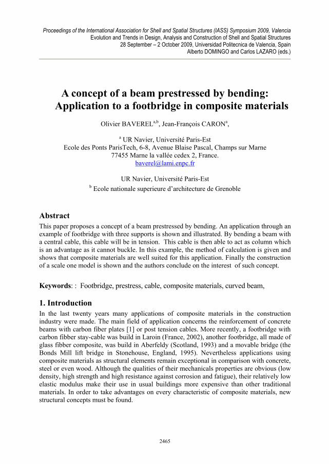
Proceedings of the International Association for Shell and Spatial Structures (IASS) Symposium 2009, Valencia Evolution and Trends in Design, Analysis and Construction of Shell and Spatial Structures
28 September – 2 October 2009, Universidad Politecnica de Valencia, Spain Alberto DOMINGO and Carlos LAZARO (eds.)
A concept of a beam prestressed by bending: Application to a footbridge in composite materials
Olivier BAVERELa,b, Jean-François CARONa,
a UR Navier, Université Paris-Est Ecole des Ponts ParisTech, 6-8, Avenue Blaise Pascal, Champs sur Marne
77455 Marne la vallée cedex 2, France. [email protected]
UR Navier, Université Paris-Est
b Ecole nationale superieure d’architecture de Grenoble
Abstract This paper proposes a concept of a beam prestressed by bending. An application through an example of footbridge with three supports is shown and illustrated. By bending a beam with a central cable, this cable will be in tension. This cable is then able to act as column which is an advantage as it cannot buckle. In this example, the method of calculation is given and shows that composite materials are well suited for this application. Finally the construction of a scale one model is shown and the authors conclude on the interest of such concept. Keywords: : Footbridge, prestress, cable, composite materials, curved beam,
1. Introduction In the last twenty years many applications of composite materials in the construction industry were made. The main field of application concerns the reinforcement of concrete beams with carbon fiber plates [1] or post tension cables. More recently, a footbridge with carbon fibber stay-cable was build in Laroin (France, 2002), another footbridge, all made of glass fibber composite, was build in Aberfeldy (Scotland, 1993) and a movable bridge (the Bonds Mill lift bridge in Stonehouse, England, 1995). Nevertheless applications using composite materials as structural elements remain exceptional in comparison with concrete, steel or even wood. Although the qualities of their mechanicals properties are obvious (low density, high strength and high resistance against corrosion and fatigue), their relatively low elastic modulus make their use in usual buildings more expensive than other traditional materials. In order to take advantages on every characteristic of composite materials, new structural concepts must be found.
2465
Proceedings of the International Association for Shell and Spatial Structures (IASS) Symposium 2009, Valencia Evolution and Trends in Design, Analysis and Construction of Shell and Spatial Structures
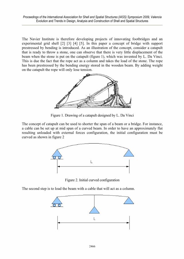
The Navier Institute is therefore developing projects of innovating footbridges and an experimental grid shell [2] [3] [4] [5]. In this paper a concept of bridge with support prestressed by bending is introduced. As an illustration of the concept, consider a catapult that is ready to throw a stone, one can observe that there is very little displacement of the beam when the stone is put on the catapult (figure 1), which was invented by L. Da Vinci. This is due the fact that the rope act as a column and takes the load of the stone. The rope has been prestressed by the bending energy stored in the wooden beam. By adding weight on the catapult the rope will only lose tension.
Figure 1. Drawing of a catapult designed by L. Da Vinci
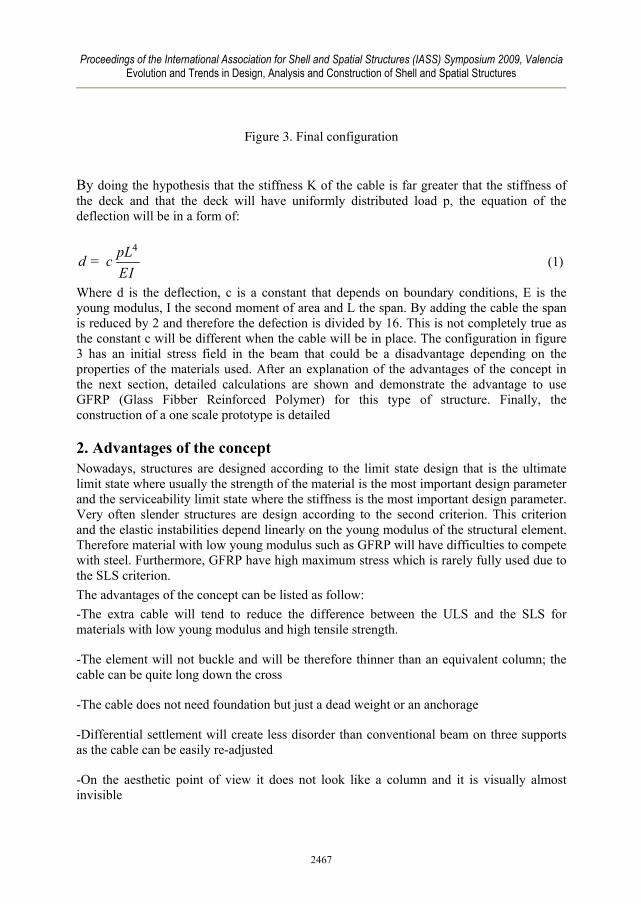
The concept of catapult can be used to shorter the span of a beam or a bridge. For instance, a cable can be set up at mid span of a curved beam. In order to have an approximately flat resulting unloaded with external forces configuration, the initial configuration must be curved as shown in figure 2
Figure 2. Initial curved configuration
The second step is to load the beam with a cable that will act as a column.
2466
Proceedings of the International Association for Shell and Spatial Structures (IASS) Symposium 2009, Valencia Evolution and Trends in Design, Analysis and Construction of Shell and Spatial Structures
Figure 3. Final configuration
By doing the hypothesis that the stiffness K of the cable is far greater that the stiffness of the deck and that the deck will have uniformly distributed load p, the equation of the deflection will be in a form of:
4pLcEI
d = (1)
Where d is the deflection, c is a constant that depends on boundary conditions, E is the young modulus, I the second moment of area and L the span. By adding the cable the span is reduced by 2 and therefore the defection is divided by 16. This is not completely true as the constant c will be different when the cable will be in place. The configuration in figure 3 has an initial stress field in the beam that could be a disadvantage depending on the properties of the materials used. After an explanation of the advantages of the concept in the next section, detailed calculations are shown and demonstrate the advantage to use GFRP (Glass Fibber Reinforced Polymer) for this type of structure. Finally, the construction of a one scale prototype is detailed
2. Advantages of the concept Nowadays, structures are designed according to the limit state design that is the ultimate limit state where usually the strength of the material is the most important design parameter and the serviceability limit state where the stiffness is the most important design parameter. Very often slender structures are design according to the second criterion. This criterion and the elastic instabilities depend linearly on the young modulus of the structural element. Therefore material with low young modulus such as GFRP will have difficulties to compete with steel. Furthermore, GFRP have high maximum stress which is rarely fully used due to the SLS criterion. The advantages of the concept can be listed as follow: -The extra cable will tend to reduce the difference between the ULS and the SLS for materials with low young modulus and high tensile strength.
-The element will not buckle and will be therefore thinner than an equivalent column; the cable can be quite long down the cross
-The cable does not need foundation but just a dead weight or an anchorage
-Differential settlement will create less disorder than conventional beam on three supports as the cable can be easily re-adjusted
-On the aesthetic point of view it does not look like a column and it is visually almost invisible
2467

Proceedings of the International Association for Shell and Spatial Structures (IASS) Symposium 2009, Valencia Evolution and Trends in Design, Analysis and Construction of Shell and Spatial Structures
3. formulae for the design of the beam In this section two different design formulae for the beam are demonstrated. The first one is based on stress and the second on the deflection or the stiffness of the beam.
3.1 Design formula based on the strength of beam
Consider the beam in figure 4, the force T of the cable will create a deflection d of the beam.
Figure 4. Deflection of the beam due to the cable
The deflection of the beam is equal to:
3
48T L
EId = (2)
Where T is the tension in the cable, E is the young modulus of the beam and I is the second moment of area of the beam.
The bending moment at mid span is
(3)
The stress field is (assuming a rectangular section cross section):
(4)
Where σmax is the maximum stress of the material.
2468
Proceedings of the International Association for Shell and Spatial Structures (IASS) Symposium 2009, Valencia Evolution and Trends in Design, Analysis and Construction of Shell and Spatial Structures
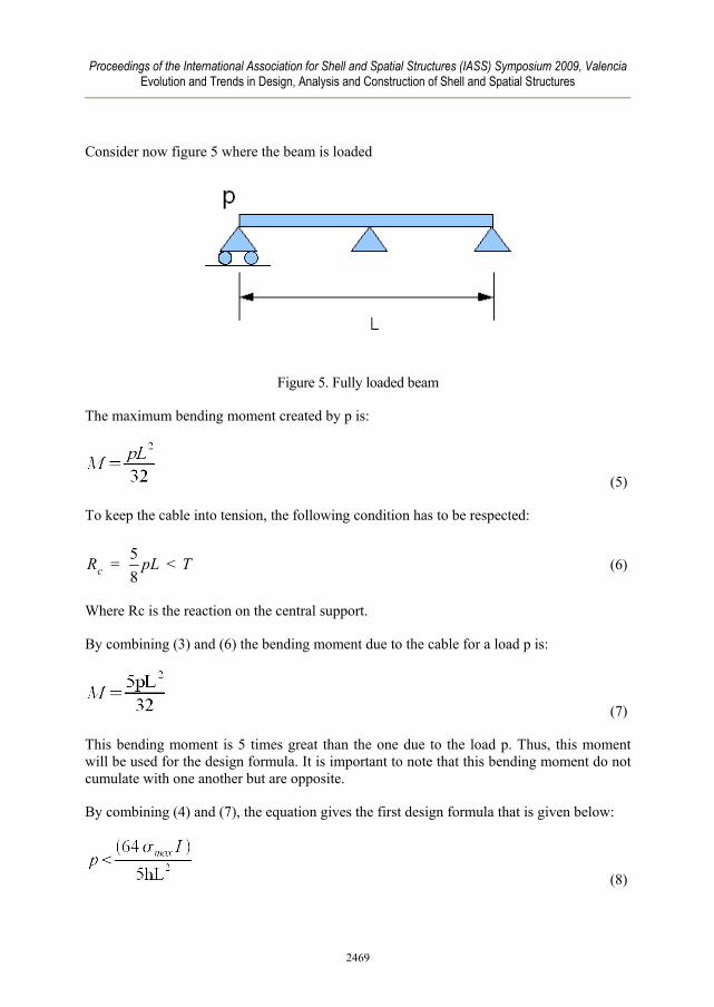
Consider now figure 5 where the beam is loaded
Figure 5. Fully loaded beam
The maximum bending moment created by p is:
(5)
To keep the cable into tension, the following condition has to be respected:
58cR pL T= < (6)
Where Rc is the reaction on the central support.
By combining (3) and (6) the bending moment due to the cable for a load p is:
(7)
This bending moment is 5 times great than the one due to the load p. Thus, this moment will be used for the design formula. It is important to note that this bending moment do not cumulate with one another but are opposite.
By combining (4) and (7), the equation gives the first design formula that is given below:
(8)
2469

Proceedings of the International Association for Shell and Spatial Structures (IASS) Symposium 2009, Valencia Evolution and Trends in Design, Analysis and Construction of Shell and Spatial Structures
One can observe that in equation 8, the load p depends on the strength of the material used and the young modulus is absent.
3.2. Design formula based on the stiffness of the beam
The loading case that gives the maximum deflection of the beam is when the beam is half loaded. In this case the maximum deflection will be the greatest around the quarter of the span.
Figure 6. Load on only one side of the beam
The central support is considered as a rigid support. By considering that the usual ratio for the deflection according to the span of (L/2)/300 which is the usual ratio taken for design of beams, the equation of the maximum deflection gives the second criterion for the external load:
3
437150
EIpL
< (9)
In this equation the load p depends on the young modulus of the materials used.
4. Domains of use of the design formulae Before comparing the two design formulae that have been introduced in the previous chapter, it is necessary to check whether the cable is structurally useful or not. Section 4.2 will show which formula gives the lower design load.
4.1 Comparison with the equivalent simply supported beam of span L without cable
The design formula based on the strength of the beam can be compared with the formula of the deflection of beam without the cable. The deflection is taken as L/300. The deflection formula is the classical for an isostatic beam:
2470
Proceedings of the International Association for Shell and Spatial Structures (IASS) Symposium 2009, Valencia Evolution and Trends in Design, Analysis and Construction of Shell and Spatial Structures
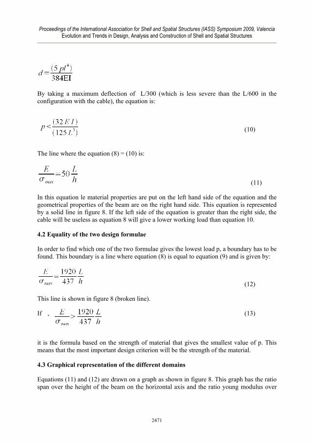
By taking a maximum deflection of L/300 (which is less severe than the L/600 in the configuration with the cable), the equation is: (10)
The line where the equation (8) = (10) is:
(11)
In this equation le material properties are put on the left hand side of the equation and the geometrical properties of the beam are on the right hand side. This equation is represented by a solid line in figure 8. If the left side of the equation is greater than the right side, the cable will be useless as equation 8 will give a lower working load than equation 10.
4.2 Equality of the two design formulae
In order to find which one of the two formulae gives the lowest load p, a boundary has to be found. This boundary is a line where equation (8) is equal to equation (9) and is given by:
(12)
This line is shown in figure 8 (broken line).
If , (13)
it is the formula based on the strength of material that gives the smallest value of p. This means that the most important design criterion will be the strength of the material.
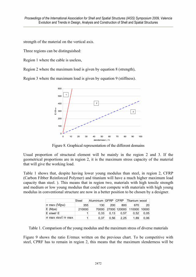
4.3 Graphical representation of the different domains
Equations (11) and (12) are drawn on a graph as shown in figure 8. This graph has the ratio span over the height of the beam on the horizontal axis and the ratio young modulus over
2471
Proceedings of the International Association for Shell and Spatial Structures (IASS) Symposium 2009, Valencia Evolution and Trends in Design, Analysis and Construction of Shell and Spatial Structures
strength of the material on the vertical axis.
Three regions can be distinguished:
Region 1 where the cable is useless,
Region 2 where the maximum load is given by equation 8 (strength),
Region 3 where the maximum load is given by equation 9 (stiffness).
0
100
200
300
400
500
600
0 10 20 30 40 50 60 70 80 90 100
slenderness L / h
E / σ
max
2
3
1
Figure 8. Graphical representation of the different domains
Usual proportion of structural element will be mainly in the region 2 and 3. If the geometrical proportions are in region 2, it is the maximum stress capacity of the material that will give the working load.
Table 1 shows that, despite having lower young modulus than steel, in region 2, CFRP (Carbon Fibber Reinforced Polymer) and titanium will have a much higher maximum load capacity than steel. ). This means that in region two, materials with high tensile strength and medium or low young modulus that could not compete with materials with high young modulus in conventional structure are now in a better position to be chosen by a designer.
Aluminium GFRP CFRP355 130 200 800 670 20
210000 70000 27000 120000 110000 100001 0,33 0,13 0,57 0,52 0,051 0,37 0,56 2,25 1,89 0,06
Steel Titanium woodσ max (Mpa)E (Mpa)E steel/ Eσ max steel /σ max
Table 1. Comparison of the young modulus and the maximum stress of diverse materials
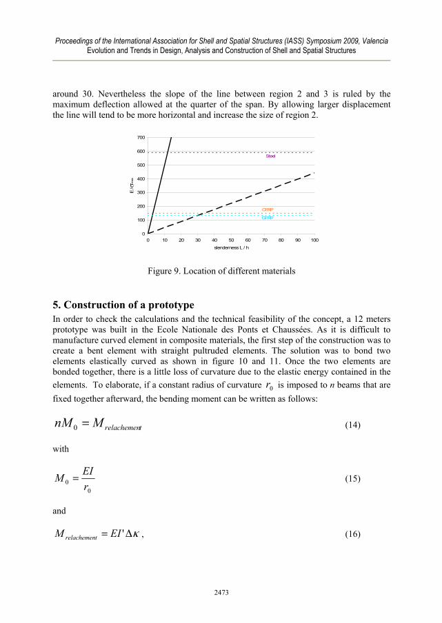
Figure 9 shows the ratio E/σmax written on the previous chart. To be competitive with steel, CPRF has to remain in region 2, this means that the maximum slenderness will be
2472
Proceedings of the International Association for Shell and Spatial Structures (IASS) Symposium 2009, Valencia Evolution and Trends in Design, Analysis and Construction of Shell and Spatial Structures
around 30. Nevertheless the slope of the line between region 2 and 3 is ruled by the maximum deflection allowed at the quarter of the span. By allowing larger displacement the line will tend to be more horizontal and increase the size of region 2.
0
100
200
300
400
500
600
700
0 10 20 30 40 50 60 70 80 90 100
slenderness L / h
E / σ
max
Steel
GFRP
CFRP
Figure 9. Location of different materials
5. Construction of a prototype In order to check the calculations and the technical feasibility of the concept, a 12 meters prototype was built in the Ecole Nationale des Ponts et Chaussées. As it is difficult to manufacture curved element in composite materials, the first step of the construction was to create a bent element with straight pultruded elements. The solution was to bond two elements elastically curved as shown in figure 10 and 11. Once the two elements are bonded together, there is a little loss of curvature due to the elastic energy contained in the elements. To elaborate, if a constant radius of curvature 0r is imposed to n beams that are fixed together afterward, the bending moment can be written as follows:
trelachemenMnM =0 (14)
with
00 r
EIM = (15)
and
κΔ= 'EIM trelachemen , (16)
2473

Proceedings of the International Association for Shell and Spatial Structures (IASS) Symposium 2009, Valencia Evolution and Trends in Design, Analysis and Construction of Shell and Spatial Structures
Where Δκ is the change of curvature between the configuration where the beams are fixed and the relaxed configuration (final configuration) with a radius of curvature R, it can thus be written
Rro
11 −=Δκ (17)
And I’ is the modulus of inertia of n beams fixed together that is equal to
InI 3'= (18)
In the present case I’ is equal to 8 I. In these calculations, it is assumed that the sections are rectangular and not hollow which is not our case but theses equations help understand the physical phenomenon.
Finally by combining (14) (15) (16) (17) and (18):
0²1rn
=Δκ (19)
And thus,
01²
² rn
nR−
= (20)
If two beams are fixed together the radius of curvature of the final configuration is 4/3 of the initial configuration.
Figure 10. Preparation of the bonding
2474
Proceedings of the International Association for Shell and Spatial Structures (IASS) Symposium 2009, Valencia Evolution and Trends in Design, Analysis and Construction of Shell and Spatial Structures
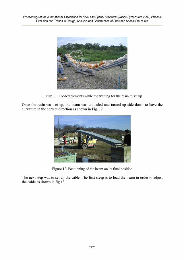
Figure 11. Loaded elements while the waiting for the resin to set up
Once the resin was set up, the beam was unloaded and turned up side down to have the curvature in the correct direction as shown in Fig. 12.
Figure 12. Positioning of the beam on its final position
The next step was to set up the cable. The first steep is to load the beam in order to adjust the cable as shown in fig 13.
2475

Proceedings of the International Association for Shell and Spatial Structures (IASS) Symposium 2009, Valencia Evolution and Trends in Design, Analysis and Construction of Shell and Spatial Structures
Figure 13. Loading of the beam in order to set up the cable
In the prototype stainless rods were preferred to cable as they were easier to get accurate adjustment. These elements are crossed to be able to take lateral displacements. The cables are anchored on the ground as shown in figure 14.
Figure 14.central support Figure 15. View of the complete footbridge
The ends of the beam are pinned on one end and simply supported on the over end. A view of the complete structure is shown in figure 13. Tests under different loading have shown that the calculations were correct.
6. Other Configurations Many configurations can be created using the principle of prestressing by bending. For instance two cables can be placed instead of one, this will have the effect of increasing region 2.
2476
Proceedings of the International Association for Shell and Spatial Structures (IASS) Symposium 2009, Valencia Evolution and Trends in Design, Analysis and Construction of Shell and Spatial Structures
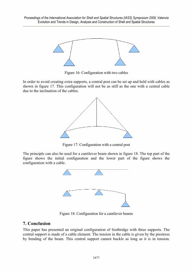
Figure 16: Configuration with two cables
In order to avoid creating extra supports, a central post can be set up and held with cables as shown in figure 17. This configuration will not be as stiff as the one with a central cable due to the inclination of the cables.
Figure 17: Configuration with a central post
The principle can also be used for a cantilever beam shown in figure 18. The top part of the figure shows the initial configuration and the lower part of the figure shows the configuration with a cable.
Figure 18: Configuration for a cantilever beams
7. Conclusion This paper has presented an original configuration of footbridge with three supports. The central support is made of a cable element. The tension in the cable is given by the prestress by bending of the beam. This central support cannot buckle as long as it is in tension.
2477
Proceedings of the International Association for Shell and Spatial Structures (IASS) Symposium 2009, Valencia Evolution and Trends in Design, Analysis and Construction of Shell and Spatial Structures
According to the geometry and the materials used, the calculations have shown that three design regions can be distinguished. In the first region the cable is useless, in the second region the strength of the materials is the main design criterion of the beam and finally in the third region the young modulus the main design criterion of the beam. In the second region, composite materials are well suited to for this concept as they have a high strength and a low young modulus. Construction of a prototype has shown that the structure can be easily constructed with standard pultruded elements. Construction has also shown that the concept works and is easy to set up. As the construction only use standard component the price of the footbridge can be highly reduced. As the composite materials have a high strength to weight ratio, this footbridge can be easily lifter and set up in a complex urban environment.
References [1] Limam, O., Nguyen, V.T. and Foret, G., « Numerical and experimental analysis of two
way slabs strengthened with CFRP strips » , Engineering Structures, n° 27, 2005, p. 841-845
[2] Douthe C., Baverel O., Caron J.F., « Formfinding of a grid shell in composite materials » , Journal of the international association for shell and spatial structures, Vol 47, n° 1, 2006, p. 53-62.
[3] Douthe C., Baverel O., Caron JF Gridshell in composite materials: towards wide span shelters Journal of the international association for shell and spatial structures Vol 48 (2007 n 3 p175-180 )
[4] Baverel O., Nooshin H. “Configuration processing of Nexorade using genetic algorithm“: Journal of the International Association for Shells and Space Structures. 2004 , vol. 45, no2, pp. 99-108
[5] Julich S., Caron J.F., Baverel O., « Selfstressed Bowstring Footbridge in FRP » Composite Structures, Volume 89, Issue 3, July 2009, Pages 489-496
2478