Embed Size (px)
Citation preview

A Component-Based Approach to Integrated Modeling
in the Geosciences: The Design of CSDMS
Scott Peckham, Eric Hutton
CSDMS, University of Colorado, 1560 30th Street, UCB 450, Boulder, CO 80309, USA
Boyana Norris
Mathematics and Computer Science Division, Argonne National Laboratory, 9700 S.Cass Ave., Argonne, IL 60439, USA
Abstract
Development of scientific modeling software increasingly requires the cou-
pling of multiple, independently developed models. Component-based soft-
ware engineering enables the integration of plug-and-play components, but
significant additional challenges must be addressed in any specific domain in
order to produce a usable development and simulation environment that also
encourages contributions and adoption by entire communities. In this pa-
per we describe the challenges in creating a coupling environment for Earth-
surface process modeling and the innovative approach that we have developed
to address them within the Community Surface Dynamics Modeling System.
Keywords:
component software, CCA, CSDMS, modeling, code generation
Email addresses: [email protected] (Scott Peckham),[email protected] (Eric Hutton), [email protected] (Boyana Norris)
Preprint submitted to Computers and Geosciences: Modeling for Environmental ChangeOctober 13, 2011

1. Introduction1
The Community Surface Dynamics Modeling System (CSDMS) project [12]2
is an NSF-funded, international effort to develop a suite of modular numerical3
models able to simulate a wide variety of Earth-surface processes, on time4
scales ranging from individual events to many millions of years. CSDMS5
maintains a large, searchable inventory of contributed models and promotes6
the sharing, reuse, and integration of open-source modeling software. It has7
adopted a component-based software development model and has created8
a suite of tools that make the creation of plug-and-play components from9
stand-alone models as automated and effortless as possible. Models or pro-10
cess modules that have been converted to component form are much more11
flexible and can be rapidly assembled into new configurations to solve a wider12
variety of scientific problems. The ease with which one component can be13
replaced by another also facilitates experimenting with different approaches14
to providing a particular type of functionality. CSDMS also has a mandate15
from the NSF to provide a migration pathway for surface dynamics modelers16
toward high-performance computing (HPC) and provides a 720-core super-17
computer for use by its members. In addition, CSDMS provides educational18
infrastructure related to physically based modeling.19
This paper presents key issues and design criteria for a component-based,20
integrated modeling system and then describes the design choices adopted21
by CSDMS to address them. CSDMS was not developed in isolation: it22
builds on and extends proven, open-source technology. The CSDMS project23
also maintains close collaborations with several other integrated modeling24
projects (such as ESMF, OpenMI and OMS) and seeks to evaluate different25
2

approaches in pursuit of those that are optimal. As with any design problem,26
myriad factors must be considered in determining what is optimal, including27
how various choices affect users and developers. Other key factors are per-28
formance, ease of maintenance, ease of use, flexibility, portability, stability,29
encapsulation, and software longevity.30
Component-based programming brings the advantages of “plug and play”31
technology into the realm of software. When buying a new peripheral for a32
computer, such as a mouse or printer, one wishes to simply plug it into the33
correct kind of port (e.g., a USB, serial, or parallel port) and have it work,34
right out of the box. For this situtation to be possible, however, a published35
standard is needed, against which the makers of peripheral devices can de-36
sign their products. For example, most computers have universal serial bus37
(USB) ports, and the USB standard is well documented. A computer’s USB38
port can always be expected to provide certain capabilities, such as the abil-39
ity to transmit data at a particular speed and the ability to provide a 5-volt40
supply of power with a maximum current of 500 mA. The benefit of this41
standardization is that one can buy a new device, plug it into a computer’s42
USB port, and start using it. Software “plug-ins” work in a similar manner,43
relying on interfaces (ports) that have well-documented structure or capabil-44
ities. In software, as in hardware, the term component refers to a unit that45
delivers a certain functionality and that can be “plugged in.”46
Component programming builds on the fundamental concepts of object-47
oriented programming, with the main difference being the introduction or48
presence of a runtime framework. Components are generally implemented as49
classes in an object-oriented language and are essentially “black boxes” that50
3

encapsulate some useful bit of functionality. The purpose of a framework is51
to provide an environment in which components can be linked together to52
form applications. The framework also provides services to all components,53
such as the linking mechanism itself. The following are some key advantages54
of component-based programming:55
• Components can be written in different languages and still communi-56
cate (via language interoperability).57
• Components are precompiled units that can be replaced, added to, or58
deleted from an application at runtime via dynamic linking.59
• Components can easily be moved to a remote location (different ad-60
dress space) without recompiling other parts of the application (via61
RMI/RPC support).62
• Components can have multiple different interfaces.63
• Components can be “stateful”; component data is retained between64
method calls over its lifetime.65
• Components can be customized at runtime with configuration param-66
eters.67
• Components facilitate code reuse and rapid comparison of different68
implementations.69
• Components facilitate efficient cooperation between groups, each doing70
what it does best.71
4

2. Background72
Here we review the role that the Common Component Architecture (CCA)73
has played in coponent programming. We then discuss three foundational74
tools that underpin CSDMS: Babel, Ccaffeine, and Bocca.75
2.1. The Common Component Architecture76
The Common Component Architecture [3] is a component architecture77
standard adopted by federal agencies (largely the Department of Energy and78
its national laboratories) and academic researchers to allow software compo-79
nents to be integrated for enhanced functionality on high-performance com-80
puting systems. The CCA Forum is a grassroots organization that started in81
1998 to promote component technology standards and code reuse for HPC.82
CCA defines standards necessary for interoperation of components developed83
in different frameworks. Components that adhere to these standards can be84
ported with relative ease to another CCA-compliant framework. While var-85
ious other component architecture standards exist in the commercial sector86
(e.g., CORBA, COM, .Net, and JavaBeans), CCA was created to fulfill the87
needs of scientific, high-performance, open-source computing that are un-88
met by these other standards. For example, scientific software requires full89
support for complex numbers, dynamically dimensioned multidimensional90
arrays, Fortran (and other languages), and multiple processor systems. Arm-91
strong et al. [3] explain the motivation for creating CCA by discussing the92
pros and cons of other component-based frameworks with regard to scien-93
tific, high-performance computing. Many of the papers in our cited references94
have been written by CCA Forum members and are helpful for learning more95
5

about the CCA. The CCA Forum has also prepared a set of tutorials called96
“A Hands-On Guide to the Common Component Architecture” [11].97
A variety of different frameworks, such as Ccaffeine [1], CCAT/XCAT [25],98
SciRUN [15], and Decaf [26], adhere to the CCA standard. Ccaffeine was de-99
signed to support both serial and parallel computing, and SciRUN and XCAT100
were designed to support distributed computing. Decaf [26] was designed by101
the developers of Babel primarily as a means of studying the technical as-102
pects of the CCA standard itself. The important point is that each of these103
frameworks adheres to the same standard, and this facilitates reuse of CCA104
components in different computational settings.105
2.2. Language Interoperability with Babel106
One feature that often distinguishes components from ordinary subrou-107
tines, software modules, or classes is that they can communicate with other108
components that may be written in a different programming language. This109
capability is often provided within a component framework and is called110
language interoperability.111
Babel [29, 14] is an open-source, language interoperability tool (consist-112
ing of a compiler and runtime) that automatically generates the “glue code”113
necessary for components written in different computer languages to com-114
municate. As illustrated in Fig. 1, Babel currently supports C, C++, For-115
tran (77, 90, 95, and 2003), Java, and Python. Babel is much more than a116
“least common denominator” solution; it even enables passing of variables117
with data types that may not normally be supported by the target language118
(e.g., objects and complex numbers). Babel was designed to support scien-119
tific, high-performance computing and is used as an integral part of CCA-120
6

compliant frameworks. It won an R&D 100 design award in 2006 for “the121
world’s most rapid communication among many programming languages in122
a single application.” It has been shown to outperform similar technologies123
such as CORBA and Microsoft’s COM and .NET.124
Figure 1: Language interoperability provided by Babel.
In order to create the glue code needed for two components written in dif-125
ferent programming languages to exchange information, Babel needs to know126
only about the interfaces of the two components. Babel therefore accepts as127
input a description of an interface in either of two “language-neutral” forms,128
XML (eXtensible Markup Language) or SIDL (Scientific Interface Defini-129
tion Language). The SIDL language (somewhat similar to CORBA’s IDL)130
was developed specifically for the Babel project. Its sole purpose is to pro-131
vide a concise description of a scientific software component interface. This132
interface description includes complete information about a component’s in-133
7

terface, such as the data types of all arguments and return values for each of134
the component’s methods (or member functions). SIDL has a complete set135
of fundamental data types to support scientific computing, from Booleans to136
double-precision complex numbers. It also supports more sophisticated data137
types such as enumerations, strings, objects, structs, and dynamic multi-138
dimensional arrays. A description of SIDL syntax and grammar can be found139
in “Appendix B: SIDL Grammar” in the Babel User’s Guide [14]. Complete140
details on how to represent a SIDL interface in XML are given in “Appendix141
C: Extensible Markup Language (XML)” of the same guide.142
2.3. The Ccaffeine Framework143
Ccaffeine [1] is the most widely used CCA framework, providing the run-144
time environment for sequential or parallel component applications. Us-145
ing Ccaffeine, component-based applications can run on diverse platforms,146
including laptops, desktops, clusters, and leadership-class supercomputers.147
Ccaffeine provides some rudimentary MPI communicator services, although148
individual components are responsible for managing parallelism internally149
(e.g., communicating with other distributed components). A CCA frame-150
work provides services, which include component instantiation and destruc-151
tion, connecting and disconnecting of ports, handling of input parameters,152
and control of MPI communicators. Ccaffeine was designed primarily to153
support single-component multiple-data (SCMD) programming, although it154
can support multiple-component multiple-data (MCMD) applications that155
implement more dynamic management of parallel resources.156
A typical CCA component’s execution consists of the following steps:157
8

• The framework loads the dynamic library for the component. Static158
linking options are also available.159
• The component is instantiated. The framework calls the setServices160
method on the component, passing a handle to itself as an argument.161
• User-specified connections to other components’ ports are established162
by the framework.163
• If the component provides a gov.cca.ports.Go port (similar to a164
“main” subroutine), its go() method can be invoked to initiate com-165
putation.166
• Connections can be made and broken throughout the life of the com-167
ponent.168
• All component ports are disconnected, and the framework calls re-169
leaseServices prior to calling the component’s destructor.170
The handle to the framework services object, which all CCA components171
obtain shortly after instantiation, can be used to access various framework172
services throughout the component’s execution. This represents the main173
difference between a class and a component: a component dynamically ac-174
cesses another component’s functionality through dynamically connecting175
ports (requiring the presence of a framework), whereas classes in object-176
oriented languages call methods directly on instances of other classes.177
2.4. Component Development with Bocca178
Bocca [2] is a tool in the CCA tool chain that was designed to help users179
create, edit, and manage a set of SIDL-based entities, including the CCA180
9

components and ports associated with a particular project. Once a set of181
CCA-compliant components and ports has been prepared, a CCA-compliant182
framework such as Ccaffeine can be used to link the components together to183
create applications or composite models.184
Bocca was developed to address usability concerns and reduce the devel-185
opment effort required to implement multilanguage component applications.186
Bocca was designed specifically to free users from mundane, time-consuming,187
low-level tasks so they can focus on the scientific aspects of their applications.188
It can be viewed as a development environment tool that allows application189
developers to perform rapid component prototyping while maintaining ro-190
bust software engineering practices suitable to HPC environments. Bocca191
provides project management and a comprehensive build environment for192
creating and managing applications composed of CCA components. Bocca193
operates in a language-agnostic way by automatically invoking the Babel194
compiler. A set of Bocca commands required to create a component project195
can be saved as a shell script, so the project can be rapidly rebuilt, if neces-196
sary. Various aspects of an existing component project can also be modified197
by typing Bocca commands interactively at a Unix command prompt.198
While Bocca automatically generates dynamic libraries, a separate tool199
can be used to create stand-alone executables for projects by automatically200
bundling all required libraries on a given platform. Examples of using Bocca201
are available in the set of tutorials called “A Hands-On Guide to the Common202
Component Architecture,” written by the CCA Forum members [11].203
10

3. Component Design Issues204
In this section we overview our CSDMS infrastructure design criteria and205
implementation approach.206
3.1. Design Criteria207
The technical goals of CSDMS include the following.208
• Support for multiple operating systems (especially Linux, Mac OS X,209
and Windows).210
• Language interoperability to support code contributions written in pro-211
cedural languages (e.g., C or Fortran) as well as object-oriented lan-212
guages (e.g., Java, C++, and Python).213
• Support for both structured and unstructured grids, requiring a spatial214
regridding tool.215
• Platform-independent graphical user interfaces (GUIs) and visualiza-216
tion capabilities where appropriate.217
• Use of well-established, open-source software standards whenever pos-218
sible (e.g., CCA, SIDL, OGC, MPI, NetCDF, OpenDAP, and XML).219
• Use of open-source tools that are mature and have well-established com-220
munities, avoiding dependencies on proprietary software (e.g., Win-221
dows, C#, and Matlab) whenever possible.222
• Support for both serial and parallel computation (multiprocessor, via223
MPI standard).224
11

• Interoperability with other coupling frameworks. Because code reuse is a225
fundamental tenet of component-based modeling, the effort required to226
use a component in another framework should be kept to a minimum.227
• Robustness and ease of maintainenance. The modeling system will228
clearly have many software dependencies, and this software infrastruc-229
ture must be updated on a regular basis.230
• Use of HPC tools and libraries. If the modeling system runs on HPC231
architectures, it should strive to use parallel tools and models (e.g.,232
VisIt, PETSc, and the ESMF regridding tool).233
• Familiarity. Model developers and contributors should not be required234
to make major changes to their existing development processes and235
habits.236
With regard to the last criterion, developers should not be required to237
convert to another programming language or make pervasive changes to their238
code (e.g., use specified data structures, libraries, or classes). They should239
be able to retain “ownership” of the code and make continual improvements240
to it. Someone should be able to componentize future, improved versions241
with minimal additional effort. The developer will likely want to continue to242
use the code outside the framework. However, some degree of code refactor-243
ing (e.g., breaking code into functions or adding a few new functions) and244
ensuring that the code compiles with an open-source compiler are considered245
reasonable requirements.246
12

3.2. Interface vs. Implementation247
Many people, when hearing the word interface, immediately think of the248
interface between a person and a computer program, such as a graphical user249
interface. Within the present context of component programming, however,250
the focus is on interfaces between components. The word interface then has a251
specific meaning, essentially the same as in the Java programming language.252
An interface is a user-defined entity or type, similar to an abstract class.253
It does not have any data fields; instead, it is a named set of methods or254
member functions, each defined completely with regard to argument types255
and return types but without any actual implementation.256
Interfaces are key to reusability or “plug and play.” Once an interface has257
been defined, one can ask: Does this component have interface A? To answer258
this question, we simply look at the methods (or member functions) that259
the component has with regard to their names, argument types, and return260
types. If a component has a given interface, then it is said to expose, or261
implement, that interface; in other words, it contains an implementation for262
each of those methods. The component may also have other methods beyond263
those that constitute a particular interface. Thus, a single component can264
expose multiple, different interfaces, allowing it to be used in a greater variety265
of settings. An analogy exists in computer hardware, where a computer or266
peripheral may have a number of different ports (e.g., USB, serial, parallel,267
and ethernet) to enable it to communicate with a wider variety of other268
components.269
The distinction between interface and implementation is an important270
theme in computer science. The word pair declaration and definition is used271
13

in a similar way. A function (or class) declaration tells what the function272
does (and how to interact with or use it) but not how it works. To see how273
the function actually works, we must look at how it has been defined or274
implemented. C and C++ programmers are familiar with this idea, which275
is similar to declaring variables, functions, classes, and other data types in a276
header file with the file name extension .h or .hpp, and then defining their277
implementations in a separate file with extension .c or .cpp.278
Most of the gadgets that we use every day (from iPods to cars) are like279
this. We must understand their interfaces in order to use them (and interfaces280
are often standardized across vendors), but often we have no idea what is281
happening inside or how they actually work, which may be quite complex.282
While the tools in the CCA tool chain are powerful and general, they do283
not provide a ready interface for linking geoscience models (or any domain-284
specific models). In CCA terminology, a port is essentially a synonym for285
interface, and a distinction is made between ports that a given component286
uses (uses ports), and those that it provides (provides ports) to other com-287
ponents. This approach provides a means of bidirectional information ex-288
change between components, unlike dataflow-based approaches that support289
only unidirectional links between components.290
Each scientific modeling community that wishes to make use of the CCA291
tools must design or select the component interface best suited to the kinds292
of models they wish to link together. This is a big job that involves both293
social and technical issues and requires a significant time investment. The294
component interface we have developed for CSDMS is described in Sections295
4 and 5.296
14

3.3. Granularity297
While components may represent any level of granularity, from a sim-298
ple function to a complete hydrologic model, the optimum level appears to299
be that of a particular physical process, such as infiltration, evaporation, or300
snowmelt. This is the level at which researchers typically want to swap out301
one method of modeling a process for another. A simpler method of param-302
eterizing a process may apply only to simplified special cases or may be used303
because there is insufficient input data to drive a more complex method. A304
different numerical method may solve the same equations with greater accu-305
racy, stability, or efficiency; it may or may not use multiple processors. Even306
the same method of modeling a given process may exhibit improved perfor-307
mance when coded in a different programming language. Physical processes308
often act within a domain that shares a physically important boundary with309
other domains (e.g., coastline and ocean-atmosphere). The fluxes between310
these domains are often of key interest and help to determine granularity.311
Some models are written in such a way that decomposing them into sepa-312
rate process components is not appropriate because of some special aspect of313
the model’s design or because decomposition would result in a loss of perfor-314
mance (e.g., speed, accuracy, or stability). For example, multiphysics mod-315
els—such as Penn State Integrated Hydrologic Model (PIHM)—represent316
many physical processes as one large, coupled set of ODEs that are then317
solved as a matrix problem on a supercomputer.318
3.4. Interchangeability and Autoconnection319
A key goal of component-based modeling is to create a collection of com-320
ponents that can be coupled together to create new and useful composite321
15

models. This goal can be achieved by providing every component with the322
same interface. A secondary goal, however, is for the coupling process to be323
as automatic as possible, that is, to require as little input as possible from324
users. In order to achieve this goal, components must somehow be grouped325
into categories according to the functionality they provide. This grouping326
must be readily apparent to both a user and the framework (or system)327
so that it is clear whether a given pair of components are interchangeable.328
But what should it mean for two components to be interchangeable? Do329
they really need to use identical input variables and provide identical output330
variables?331
To clarify this issue, consider the physical process of infiltration within332
a hydrologic model. An infiltration component must provide the infiltration333
rate at the surface, because it represents a loss term in the overall hydro-334
logic budget. If the domain of the infiltration component is restricted to335
the unsaturated zone, above the water table, then it may also need to pro-336
vide a vertical flow rate at the water table boundary. Thus, any infiltration337
component must provide fluxes at the (top and bottom) boundaries of its338
domain. To do so, it needs variables such as flow depth and rainfall rate that339
are outside its domain and computed by another component. Hydrologists340
use a variety of different methods and approximations to compute surface341
infiltration rate. The Richards 3D method, for example, is a more rigor-342
ous approach that tracks four state variables throughout the domain. The343
Green-Ampt method, on the other hand, makes a number of simplifying as-344
sumptions, computes a smaller set of state variables, and does not resolve345
the vertical flow dynamics to the same level of detail (i.e., piston flow, sharp346
16

wetting front). As a result, the Richards 3D and Green-Ampt infiltration347
components use a different set of input variables and provide a different set348
of output variables. Nevertheless, they both provide certain, key outputs such349
as surface infiltration rate and can therefore be used “interchangeably” in a350
hydrologic model.351
Autoconnection of components is important from a user’s point of view.352
Components typically require many input variables and produce many out-353
put variables. Users quickly become frustrated when they need to manually354
create all of these pairings or connections, especially when using more than355
just two or three components at a time. CSDMS currently employs an ap-356
proach to autoconnection that involves providing interfaces (i.e., CCA ports)357
with different names to reflect their intended use (or interchangeability), even358
though they use the same interface internally.359
4. The Basic Model Interface360
Most Earth-science models initialize a set of state variables (often as 1D,361
2D, or 3D arrays) and then execute of series of time steps that advance the362
variables forward in time according to physical laws (e.g., mass conservation)363
or some other set of rules. Hence, the underlying source code tends to follow a364
standard pattern that consists of three main parts. The first part comprises365
all source code prior to the start of the time loop and serves to set up or366
initialize the model. The second part comprises all source code within the367
time loop and is where the main functionality of the model is implemented368
to update state variables with each time step. The third part consists of all369
source code after the end of the time loop and serves to tear down, or finalize,370
17

the model. Note that root-finding and relaxation algorithms follow a similar371
pattern even if the iterations do not represent timestepping.372
All the model coupling projects that we are aware of (including CSDMS,373
ESMF, OMS, and OpenMI) have developed a component interface that pro-374
vides initialize, update, and finalize functions. This approach provides a375
caller with fine-grained control that is essential for model coupling and al-376
lows the caller to bypass the model’s own time loop.377
The streamlined approach developed by CSDMS for converting mod-378
els into plug-and-play components utilizes two new interfaces in a two-level379
wrapping process. Recall that a component interface is simply a named set380
of functions (called methods) that have been defined completely in terms of381
their names, arguments, and return values. The first-level interface, called382
the Basic Model Interface (BMI), is the only one that model contributors are383
required to implement. The purpose of the BMI is to ensure that the model384
“fits into” the second-level wrapper, called the CSDMS Component Model385
Interface (CMI), discussed in the next section. By design, the BMI uses only386
simple data types and is easy to implement in all of the languages supported387
by CSDMS. However, it provides all of the information that is needed at the388
CMI level for plug-and-play modeling.389
Table 1 summarizes the key BMI functions. BMI.initialize() typically390
reads data from a configuration file, initializes variables, opens output files,391
and stores data in a “handle” for non-object-oriented languages. BMI.update()392
advances the state variables by one model time step. BMI.finalize() typically393
frees resources and closes files. Several “getter” and “setter” functions, whose394
details differ between languages, allow the CMI wrapper to retrieve data from395
18

and load data into the model. The CMI wrapper must be able to retrieve396
anything it needs for model coupling, such as lists of input and output vari-397
able names; any variable’s units, rank or data type; and a description of the398
model’s grid or mesh. The BMI functions that must be provided to fully399
describe a model’s computational grid (not shown) depend on the type of400
grid, e.g. uniform, orthogonal curvilinear, or unstructured.401
Table 1. Summary of BMI functions.
opaque initialize( string config file )
Returns a “handle”. Initialize variables, open files, etc.
void update( double dt )
Advance state variables by one time step (model’s own, if dt = -1)
void finalize()
Free resources, close files, reporting, etc.
void run model( string config file )
Do a complete model run. (Not called by CMI.)
array<string> get input var names()
Return a list of model’s input vars.
array<string> get output var names()
Return a list of model’s output vars.
string get attribute( string att name )
Return mesh type (raster/ugrid), time step type (fixed/adaptive), etc.
string get var type( string long var name )
Return variable’s type, e.g. ‘double’, ‘int’
string get var units( string long var name )
Return variable’s units, e.g. ‘meters’ (UD units standard)
int get var rank( string long var name )
Return variable’s number of dimensions (0 for scalars)
(continued on next page)
19
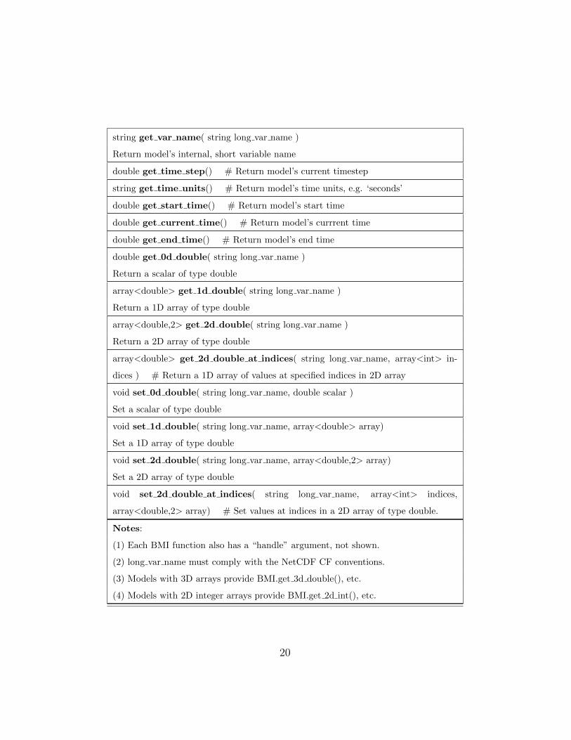
string get var name( string long var name )
Return model’s internal, short variable name
double get time step() # Return model’s current timestep
string get time units() # Return model’s time units, e.g. ‘seconds’
double get start time() # Return model’s start time
double get current time() # Return model’s currrent time
double get end time() # Return model’s end time
double get 0d double( string long var name )
Return a scalar of type double
array<double> get 1d double( string long var name )
Return a 1D array of type double
array<double,2> get 2d double( string long var name )
Return a 2D array of type double
array<double> get 2d double at indices( string long var name, array<int> in-
dices ) # Return a 1D array of values at specified indices in 2D array
void set 0d double( string long var name, double scalar )
Set a scalar of type double
void set 1d double( string long var name, array<double> array)
Set a 1D array of type double
void set 2d double( string long var name, array<double,2> array)
Set a 2D array of type double
void set 2d double at indices( string long var name, array<int> indices,
array<double,2> array) # Set values at indices in a 2D array of type double.
Notes:
(1) Each BMI function also has a “handle” argument, not shown.
(2) long var name must comply with the NetCDF CF conventions.
(3) Models with 3D arrays provide BMI.get 3d double(), etc.
(4) Models with 2D integer arrays provide BMI.get 2d int(), etc.
20

Table 2. Summary of CMI functions.
bool initialize( string config file )
bool run for( double time interval, string time units )
void finalize()
bool run model( string config file, string stop rule, array<double> stop vars)
array<> get values( string long var name )
void set values( string long var name, array<> values )
string get status() # (see BMI set status)
void set status( string status )
string get mode() # (‘driver’ or ‘nondriver’)
void set mode( string mode )
array<string> get input var names()
Return a list of model’s input vars (CF convention long names).
array<string> get output var names()
Return a list of model’s output vars (CF convention long names).
string get var units( string long var name )
string get attribute( string att name )
Return mesh type (raster/ugrid), time step type (fixed/adaptive), etc.
void setServices() # (used by CCA framework)
void releaseServices() # (used by CCA framework)
5. The CSDMS Component Model Interface402
A model that provides the BMI functions is ready to be converted to a403
CSDMS plug-and-play component using automated tools that provide it with404
the CSDMS Component Model Interface. Therefore, model contributors do405
not need to know anything about the CMI or technical CCA framework con-406
cepts such as ports. The functions in the CMI allow CSDMS components to407
communicate and share data with other CSDMS components even if they are408
21

written in a different language, use a different grid, use different units, or use409
a different timestepping scheme. A model wrapped as a CSDMS component410
becomes an object and can maintain its state variables between method calls,411
regardless of whether it was written in an object-oriented language.412
A CSDMS component must communicate with (make function calls to)413
five entities: (1) the model that it wraps, (2) other CSDMS components, (3)414
itself, (4) CSDMS service components and (5) the CSDMS/CCA framework.415
Each entity provides interface functions for this purpose. BMI functions416
are used to communicate with the underlying, wrapped model. CMI func-417
tions are used to communicate with other CSDMS components (and itself).418
Service components each have their own interface and provide a rich set of419
useful services, such as spatial regridding, interpolation in time, unit conver-420
sion, and writing of output to a standard file format (e.g., NetCDF). Every421
CSDMS component has a setServices() function that the framework calls to422
instantiate the component and give it a handle for calling framework services423
(e.g., services.getPort()).424
In CCA jargon, the “IMPL file” is where all the CMI functions are imple-425
mented. In our design, the CMI functions make calls only to the interfaces426
of the entities just discussed. Anything that is needed from the model is427
obtained through standardized BMI function calls. This means that essen-428
tially the same IMPL file can be used for all components written in a given429
language, such as Fortran.430
By design, our process to convert a model with a BMI interface to a plug-431
and-play component with a CMI interface is noninvasive. Model contributors432
do not insert any calls in their (BMI-compliant) code to CSDMS utilities or433
22

services. The BMI functions do not call any external entity.434
Babel is used during compilation to create language bindings, or “glue435
code”, that allow the component to share data with other CSDMS compo-436
nents that may have been written in another language. In most cases, CS-437
DMS components access each other’s state variables through references (pass-438
by-reference) rather than copying data (pass-by-copy), as this approach re-439
sults in higher performance. However, since Babel supports Remote Method440
Invocation (RMI), it is not necessary for CSDMS components to reside in441
the same address space and they could even be coupled across a network.442
Table 2 summarizes the key CMI functions. CMI.initialize() must get443
and save the CCA ports it needs to call other components. It then calls444
CMI.initialize() on those components, if necessary, and finally calls BMI.initialize().445
CMI.run for() first calls CMI.run for() on the components it needs data from446
and retrieves that data. It then makes as many calls to BMI.update()447
as necessary to span a time interval. Because of this fine-grained control,448
CMI.run for() can then call service components to do other tasks after each449
update, such as write data to NetCDF files at a specified interval, advance450
a progress bar, or check a stopping rule. CMI.finalize() releases CCA ports451
and calls BMI.finalize(). CMI.get values() takes a long variable name argu-452
ment (following the NetCDF CF conventions) and makes calls to various BMI453
methods to retrieve the requested data. It then uses service components, if454
necessary, to convert units to those needed by the caller or perform spatial455
regridding to the caller’s grid. CMI.set values() does unit conversion and456
regridding, if necessary, before loading variables into the model’s state using457
BMI methods. A more detailed explanation of the CMI will be provided in458
23

a subsequent paper.459
6. Service Components: Tools That Any Component Can Use460
It is helpful for certain low-level tools or utilities to be encapsulated in461
special components called service components that can be automatically in-462
stantiated by a CCA framework on startup. Unlike other components, which463
users may assemble graphically into larger applications, users do not inter-464
act with service components directly. However, CMI functions can call the465
methods of service components through service ports. The use of service466
components allows CSDMS to maintain code for a shared functionality in467
a single place and to make that functionality available to all components468
regardless of the implementation language. Any CCA component can be469
“promoted” to a service component by registering it as such using a CCA470
port called gov.cca.ports.ServiceRegistry.471
CMI functions call service components for tasks like spatial regridding,472
as explained previously. An example regridding scenario is shown in Fig-473
ure 2. CSDMS uses regridding tools from both the ESMF and OpenMI474
projects. The ESMF regridder is implemented in Fortran and uses multiple475
processors. It also supports sophisticated options such as mass-conservative476
interpolation.477
7. Component Wrapping Issues478
For a small or simple model, little effort may be needed to rewrite the479
model in a preferred language and with a particular interface. Rewriting480
large models, however, is both time-consuming and error prone. In addition,481
24

(a) Voronoi cells. (b) Intersecting raster and Voronoi cells.
(c) Voronoi cells before regridding. (d) After regridding to raster cells.
Figure 2: Regridding example.
most large models are under continual development, and a rewritten version482
will not see the benefits of future improvements. Thus, for code reuse to483
be practical, we need a language interoperability tool (such as Babel), so484
that components do not need to be converted to a different language, and485
a wrapping procedure to provide existing code with a new calling interface.486
Wrapping applies to the “outside” (interface) of a component vs. its “inside”487
25

(implementation), so it tends to be a noninvasive and practical way to convert488
existing models into components.489
7.1. Wrapping for Object-Oriented Languages490
Component-based programming is essentially object-oriented program-491
ming with the addition of a runtime framework. Thus, if a model has been492
written as a class with a BMI interface, it is straightforward to convert it493
to a component with a CMI interface. For object-oriented languages, all494
the model data is encapsulated in the model object, and the built-in use495
of namespaces makes compilation straightforward. The object-oriented lan-496
guages supported by Babel are C++, Java, and Python.497
7.2. Wrapping for Procedural Languages498
Languages such as C or Fortran (up to 2003) do not provide object-499
oriented primitives for encapsulating data and functionality. Because component-500
based programming requires such encapsulation, the CCA provides a means501
to produce object-oriented software even in languages that do not support it502
directly. Specifically, all of the model’s data and functions must be bundled503
and a suitable namespace created. A model contributor provides implemen-504
tations for each of the BMI functions. In the case of Fortran, the model’s505
variables are encapsulated in named modules that are accessed via “use mod-506
ule name.” The model is then compiled as a set of shared library functions507
using Babel.508
When the model is wrapped with a CMI interface, the data and functions509
are made accessible to all the other CMI functions by using a “handle” that510
provides a reference to the model object. This handle is passed as the first511
26

argument to each of the interface functions so that they can operate on a512
particular instance of a model. For example, in C this handle could simply513
be a pointer to the object, and in Fortran the handle could be an index into514
a table of opaque objects in a system table. Model handles are allocated and515
deallaocated in the CMI initialize and finalize functions, respectively.516
The creation of class or component wrappers also enables the careful517
definition of namespaces, thus reducing potential conflicts when integrating518
with other classes or components. In non-object-oriented languages, symbols519
(e.g., function names) are prefixed with the names of all enclosing packages520
and parent class. This approach greatly reduces the potential build-, link-,521
or runtime name conflicts that can result when multiple components define522
the same interfaces (e.g., the initialize, update, and finalize methods).523
8. The CSDMS Modeling Tool524
As explained in Section 2.3, Ccaffeine is a CCA-compliant framework525
for connecting components to create applications. From a user’s point of526
view, Ccaffeine is a low-level tool that executes a sequence of commands527
in a Ccaffeine script. The commands in the Ccaffeine scripting language528
are fairly simple, but many people prefer using a GUI because it provides529
a natural, visual representation of the connected components as boxes with530
buttons connected by wires. It can also prevent common scripting errors531
and offer many other convenient features. The CCA Forum developed such532
a GUI, called Ccafe-GUI, that presented components as boxes in a palette533
that can be moved into an arena (workspace) and connected by wires. It534
also allows component configurations and settings to be saved in BLD files535
27

and instantly reloaded later. As a lightweight and platform-independent tool536
written in Java, Ccafe-GUI can be installed and used on any computer with537
Java support to create a Ccaffeine script. This script can then be sent to a538
remote, possibly high-performance computer for execution.539
While Ccafe-GUI was certainly useful, the CSDMS project realized that it540
could be improved and extended in numerous ways to make it more powerful541
and more user-friendly. In addition, these changes not only would serve the542
CSDMS community but could be shared back with the CCA community.543
The new version, called CMT (CSDMS Modeling Tool), works with any544
CCA-compliant components, not just CSDMS components. Significant new545
features of CMT 1.6 include the following.546
• Integration with a powerful visualization tool called VisIt (see below).547
• New, “wireless” paradigm for connecting components (see below).548
• A login dialog that prompts users for remote server login information.549
• Job management tools that are able to submit jobs to processors of a550
cluster.551
• “Launch and go”: launch a model run on a remote server and then552
shut down the GUI (the model continues running remotely).553
• New file menu entry: “Import Example Configuration.”554
• A help menu with numerous help documents and links to websites.555
• Ability to submit bug reports to CSDMS.556
28

• Ability to do file transfers to and from a remote server.557
• Help button in tabbed dialogs to launch component-specific HTML558
help.559
• Support for droplists and mouse-over help in tabbed dialogs.560
• Support for custom project lists (e.g., projects not yet ready for re-561
lease).562
• A separate “driver palette” above the component palette.563
• Support for numerous user preferences, many relating to appearance.564
• Extensive cross-platform testing and “bulletproofing.”565
CMT provides integrated visualization by using VisIt. VisIt [47] is an566
open-source, interactive, parallel visualization and graphical analysis tool for567
viewing scientific data. It was developed by the U.S. Department of Energy568
Advanced Simulation and Computing Initiative to visualize and analyze the569
results of simulations ranging from kilobytes to terabytes. VisIt was designed570
so that users can install a client version on their PC that works together with571
a server version installed on a high-performance computer or cluster. The572
server version uses multiple processors to speed rendering of large data sets573
and then sends graphical output back to the client version. VisIt supports574
about five dozen file formats and provides a rich set of visualization features,575
including the ability to make movies from time-varying databases. CSDMS576
uses a service component to provide other components with the ability to577
write their output to NetCDF files that can be visualized with VisIt. Output578
29

can be 0D, 1D, 2D, or 3D data evolving in time, such as a time series (e.g.,579
a hydrograph), a profile series (e.g., a soil moisture profile), a 2D grid stack580
(e.g., water depth), a 3D cube stack, or a scatter plot of XYZ triples.581
Another innovative feature of CMT 1.6 is that it can toggle between the582
original, wired mode and a new wireless mode. CSDMS found that displaying583
connections between components as wires (i.e., red lines) did not scale well to584
configurations with several components and multiple ports. In wireless mode,585
a component dragged from the palette to the arena appears to broadcast what586
it can provide (i.e., CCA provides ports) to other components in the arena587
(using a concentric circle animation). Any components in the arena that588
need to use that kind of port get linked automatically to the new one, as589
indicated using unique, matching colors (Fig. 3).590
CSDMS continues to make usability improvements to the CMT and used591
it to teach a graduate-level course on surface process modeling at the Univer-592
sity of Colorado, Boulder, in 2010. Several features of the CMT are ideal for593
teaching, including (1) the ability to save prebuilt component configurations594
and their settings in BLD files, (2) the File >> Import Example Configu-595
ration feature, (3) a standardized HTML help page for each component, (4)596
a uniform, tabbed-dialog GUI for each component, (5) rapid comparison of597
different approaches by swapping one component for another, (6) the simple598
installation procedure, and (7) the ability to use remote resources.599
9. Providing Components with a Uniform Help System and GUI600
Within a framework where it is easy to connect, interchange, and run601
coupled models, some users may treat components as black boxes and ignore602
30

the underlying assumptions that a component was built upon. They may603
even couple two components for which coupling does not make sense. To604
combat this problem, each CSDMS component is bundled with an HTML605
help document, easily accessible through the CMT, that describes the model606
it wraps. These documents are standardized to include the following.607
• Extended model description (along with references)608
• Listing and brief description of the component’s uses and provides ports609
• Main equations of the model610
• Sample input and output611
• Acknowledgment of the model developer(s)612
CSDMS components also include XML files that describe their user-613
editable input variables. These files contain XML elements with detailed614
information about each variable including a default value, range of accept-615
able values, short and long descriptions, units, and data type. Using this616
XML file, the CMT automatically generates a graphical user interface for617
each component as a tabbed dialog. Despite significant differences between618
different models’ input files, this provides CMT users with a uniform in-619
terface across all components. Furthermore, the GUI checks user input for620
errors and provides easily accessible help within the same environment. Input621
obtained from the GUI is automatically saved into whatever type of input622
or configuration file the model was designed to use. This process is done by623
replacing placeholders in an input file template with values from the GUI.624
31

10. Conclusions625
CSDMS has developed a component-based approach to integrated mod-626
eling that draws on the combined power of several open-source tools such627
as Babel, Bocca, Ccaffeine, the ESMF regridding tool, and the VisIt visu-628
alization tool. This noninvasive approach includes the new BMI and CMI629
interfaces. CSDMS also draws on the combined knowledge and creative effort630
of a large community of Earth-surface dynamics modelers and computer sci-631
entists. Using a variety of tools, standards and protocols, CSDMS converts632
a heterogeneous set of open-source, user-contributed models into a suite of633
plug-and-play modeling components that can be reused in many different634
contexts. The CSDMS model repository currently contains more than 160635
models and tools. Of those, 50 have been converted into components that636
can be used in coupled modeling scenarios with Ccaffeine or the CMT. An637
up-to-date list is maintained at csdms.colorado.edu. As with the model repos-638
itory as a whole, CSDMS components cover the breadth of surface dynamics639
systems.640
All the software that underlies CSDMS is installed and maintained on641
its high-performance cluster. CSDMS members have accounts on this clus-642
ter and access its resources using a lightweight, Java-based client application643
called the CSDMS Modeling Tool (CMT) that runs on virtually any desk-644
top or laptop computer. This approach is a type of community cloud since645
it provides remote access to numerous resources. This centralized cloud ap-646
proach offers many advantages including (1) simplified maintenance, (2) more647
reliable performance, (3) automated backups, (4) remote storage and com-648
putation (user’s PC remains free), (5) ability for many components (such649
32

as ROMS) and tools (such as VisIt and ESMF’s regridder) to use parallel650
computation, (6) need for users to install only a lightweight client on their651
PC, (7) less need for technical support, and (8) ability to submit and run652
multiple jobs.653
Acknowledgments654
CSDMS gratefully acknowledges major funding through a cooperative655
agreement with the National Science Foundation (EAR 0621695). Addi-656
tional work was supported by the Office of Advanced Scientific Computing657
Research, Office of Science, U.S. Dept. of Energy, under Contracts DE-AC02-658
06CH11357 and DE-FC-0206-ER-25774.659
References660
[1] Allan, B., Armstrong, R., Lefantzi, S., Ray, J., Walsh, E., Wolfe, P.,661
2010. Ccaffeine – a CCA component framework for parallel computing.662
http://www.cca-forum.org/ccafe/.663
[2] Allan, B. A., Norris, B., Elwasif, W. R., Armstrong, R. C., Dec. 2008.664
Managing scientific software complexity with Bocca and CCA. Scientific665
Programming 16 (4), 315–327.666
[3] Armstrong, R., Gannon, D., Geist, A., Keahey, K., Kohn, S., McInnes,667
L., Parker, S., Smolinski, B., 1999. Toward a Common Component Ar-668
chitecture for high-performance scientific computing. In: Proc. 8th IEEE669
Int. Symp. on High Performance Distributed Computing.670
33

[4] Ashton, A., Kettner, A. J., Hutton, E. W. H., 2011. Progress in coupling671
between coastline and fluvial dynamics. Computers & Geosciences (this672
issue).673
[5] Ashton, A., Murray, A. B., Arnoult, O., 2001. Formation of coastline674
features by large-scale instabilities induced by high-angle waves. Nature675
414, 296–300.676
[6] Balay, S., Brown, J., , Buschelman, K., Eijkhout, V., Gropp, W. D.,677
Kaushik, D., Knepley, M. G., McInnes, L. C., Smith, B. F., Zhang,678
H., 2010. PETSc users manual. Tech. Rep. ANL-95/11 - Revision 3.1,679
Argonne National Laboratory.680
[7] Balay, S., Brown, J., Buschelman, K., Gropp, W. D., Kaushik, D., Kne-681
pley, M. G., McInnes, L. C., Smith, B. F., Zhang, H., 2011. PETSc web682
page. Http://www.mcs.anl.gov/petsc.683
[8] Balay, S., Gropp, W. D., McInnes, L. C., Smith, B. F., 1997. Effi-684
cient management of parallelism in object oriented numerical software685
libraries. In: Arge, E., Bruaset, A. M., Langtangen, H. P. (Eds.), Modern686
Software Tools in Scientific Computing. Birkhauser Press, pp. 163–202.687
[9] Bernholdt D. (PI), 2010. TASCS Center.688
http://www.scidac.gov/compsci/TASCS.html.689
[10] Buttler, H., AprilJune 2005. A guide to the python uni-690
verse for esri users. ArcUser Mag.Available online at691
http://www.esri.com/news/arcuser/.692
34

[11] CCA Forum, 2010. A hands-on guide to the Common Component Ar-693
chitecture. http://www.cca-forum.org/tutorials/.694
[12] CSDMS, 2011. Community Surface Dynamics Modeling System (CS-695
DMS). http://csdms.colorado.edu.696
[13] CUAHSI, 2011. Consortium of Universities for the Advancement of the697
Hydrological Sciences Inc. . http://www.cuahsi.org.698
[14] Dahlgren, T., Epperly, T., Kumfert, G., Leek, J., 2007. Babel User’s699
Guide. CASC, Lawrence Livermore National Laboratory, UCRL-SM-700
230026, Livermore, CA.701
[15] de St. Germain, J. D., Morris, A., Parker, S. G., Malony, A. D., Shende,702
S., May 15-17 2002. Integrating performance analysis in the Uintah703
software development cycle. In: Proceedings of the 4th International704
Symposium on High Performance Computing (ISHPC-IV). pp. 190–206.705
URL http://www.sci.utah.edu/publications/dav00/ishpc2002.pdf706
[16] Diachin L. (PI), 2011. Center for Interoperable Tech-707
nologies for Advanced Petascale Simulations (ITAPS).708
http://www.scidac.gov/math/ITAPS.html.709
[17] EJB, 2011. Enterprise Java Beans Specification.710
http://java.sun.com/products/ejb/docs.html.711
[18] ESMF Joint Specification Team, 2011. Earth System Modeling Frame-712
work (ESMF) Website. http://www.earthsystemmodeling.org/.713
35

[19] FRAMES, 2011. Framework for Risk Analysis of Multi-Media Environ-714
mental Systems (FRAMES). http://mepas.pnl.gov/FRAMESV1/.715
[20] Hill, C., DeLuca, C., Balaji, V., Suarez, M., da Silva, A., ESMF Joint716
Specification Team, 2004. The architecture of the Earth System Model-717
ing Framework. Computing in Science and Engineering 6, 18–28.718
[21] Hutton, E. W. H., Syvitski, J. P. M., 2008. Sedflux-2.0: An advanced719
process-response model that generates three-dimensional stratigraphy.720
Computers & Geosciences 34 (10), 1319–1337.721
[22] Kessler, M. A., Anderson, R. S., Briner, J. P., 2008. Fjord insertion722
into continental margins driven by topographic steering of ice. Nature723
Geoscience 1, 365–369.724
[23] Kettner, A. J., Syvitski, J. P. M., 2008. Hydrotrend version 3.0: a725
climate-driven hydrological transport model that simulates discharge726
and sediment load leaving a river system. Computers & Geosciences727
34 (10), 1170–1183.728
[24] Keyes D. (PI), 2011. Towards Optimal Petascale Simulations (TOPS)729
Center. http://tops-scidac.org/.730
[25] Krishnan, S., Gannon, D., April 2004. XCAT3: A framework for CCA731
components as OGSA services. In: Proceedings of the 9th International732
Workshop on High-Level Parallel Programming Models and Supportive733
Environments (HIPS 2004). IEEE Computer Society, pp. 90–97.734
[26] Kumfert, G., April 2003. Understanding the CCA Specification Using735
36

Decaf. Lawrence Livermore National Laboratory.736
URL http://www.llnl.gov/CASC/components/docs/decaf.pdf737
[27] Larson, J. W., 2009. Ten organising principles for coupling in multi-738
physics and multiscale models. ANZIAM Journal 47, C1090–C1111.739
[28] Larson, J. W., Norris, B., 2007. Component specification for parallel740
coupling infrastructure. In: Gervasi, O., Gavrilova, M. L. (Eds.), Pro-741
ceedings of the International Conference on Computational Science and742
its Applications (ICCSA 2007). Vol. 4707 of Lecture Notes in Computer743
Science. Springer-Verlag, pp. 56–68.744
[29] Lawrence Livermore National Laboratory, 2011. Babel.745
http://www.llnl.gov/CASC/components/babel.html.746
[30] Lucas R. (PI), 2011. Performance Engineering Research Institute747
(PERI). http://www.peri-scidac.org.748
[31] MathWorks, 2011. MATLAB - The Language of Technical Computing.749
http://www.mathworks.com/products/matlab/.750
[32] Message Passing Interface Forum, 1998. MPI2: A message passing in-751
terface standard. High Performance Computing Applications 12, 1–299.752
[33] NET, 2011. Microsoft .NET Framework.753
http://www.microsoft.com/net/.754
[34] NetCDF, 2011. NetCDF. http://www.unidata.ucar.edu/packages/netcdf.755
[35] OMP, 2011. Object Modeling System v3.0.756
http://www.javaforge.com/project/oms.757
37

[36] Ong, E. T., Larson, J. W., Norris, B., Jacob, R. L., Tobis, M., Steder,758
M., 2008. A multilingual programming model for coupled systems. In-759
ternational Journal for Multiscale Computational Engineering 6, 39–51.760
[37] Open Geospatial Consortium, 2011. OGC Standards and Specifications.761
http://www.opengeospatial.org/.762
[38] Parker, G., 2011. 1d sediment transport morphodynam-763
ics with applications to rivers and turbidity currents.764
http://vtchl.uiuc.edu/people/parkerg/morphodynamic e-book.htm.765
[39] Peckham, S., 2008. Geomorphometry and spatial hydrologic modeling.766
Vol. 33 of Geomorphometry: Concepts, Software and Applications. De-767
velopments in Soil Science. Elsevier, Ch. 25, pp. 579–602.768
[40] Peckham, S. D., Goodall, J. L., 2011. Driving plug-and-play compo-769
nents with data from web services: A demonstration of interoperability770
between CSDMS and CUAHSI-HIS. Computers & Geosciences (this is-771
sue).772
[41] Rosen, L., 2004. Open Source Licensing: Software Freedom and Intellec-773
tual Property Law. Prentice Hall, http://rosenlaw.com/oslbook.htm.774
[42] T. Oliphant et al., 2011. Scientific Computing Tools for Python –775
NumPy. http://numpy.scipy.org/.776
[43] The MCT Development Team, 2006. Model Coupling Toolkit (MCT)777
Web Site. http://www.mcs.anl.gov/mct/.778
38

[44] The OpenMI Association, 2011. The Open Modeling Interface779
(OpenMI). http://www.openmi.org.780
[45] Tucker, G. E., Lancaster, S. T., Gasparini, N. M., Bras, R. L., 2001. The781
Channel-Hillslope Integrated Landscape Development (CHILD) Model.782
Academic/Plenum Publishers, pp. 349–388.783
[46] United States Department of Energy, 2011. SciDAC Initiative homepage.784
http://scidac.gov/.785
[47] VisIt, 2011. VisIt. http://wci.llnl.gov/codes/visit.786
[48] XML, 2011. Extensible Markup Language (XML).787
http://www.w3.org/XML/.788
The submitted manuscript has been created
by UChicago Argonne, LLC, Operator of Ar-
gonne National Laboratory (“Argonne”). Ar-
gonne, a U.S. Department of Energy Office of
Science laboratory, is operated under Contract
No. DE-AC02-06CH11357. The U.S. Govern-
ment retains for itself, and others acting on
its behalf, a paid-up, nonexclusive, irrevocable
worldwide license in said article to reproduce,
prepare derivative works, distribute copies to
the public, and perform publicly and display
publicly, by or on behalf of the Government.
789
39

Figure 3: Hydrologic model assembled in the CMT by dragging interchangeable process
components from the palette to the arena.
40