Embed Size (px)
Citation preview

A COMPARISON OF WIRELESS NETWORK
PROTOCOLS FROM A SIMULATION PERSPECTIVE
by
Robert Bathmann
A Thesis
Presented to the Faculty of
Bucknell University
In Partial Fulfillment of the Requirements for the Degree of
Bachelor of Science with Honors in Computer Science
May 4, 2009
Approved:Felipe PerroneThesis Advisor
Xiannong MengChair, Department of Computer Science

ii
Acknowledgments
Thank you to everyone who helped me complete my Honors Thesis. I could nothave done it without all the support I received from many people. I want to especiallythank:
• Felipe Perrone, for all the hard work and time he spent working with me on mythesis. He always provided me answers when I had questions and encouragementwhen I felt discouraged. Although he insisted that he would become my worstenemy, he was always a friend.
• Kristen Brown, for forcing (nagging?) me to work on my thesis when I otherwisewould have not.
• My family and friends who supported me while writing my thesis and through-out my education
iii
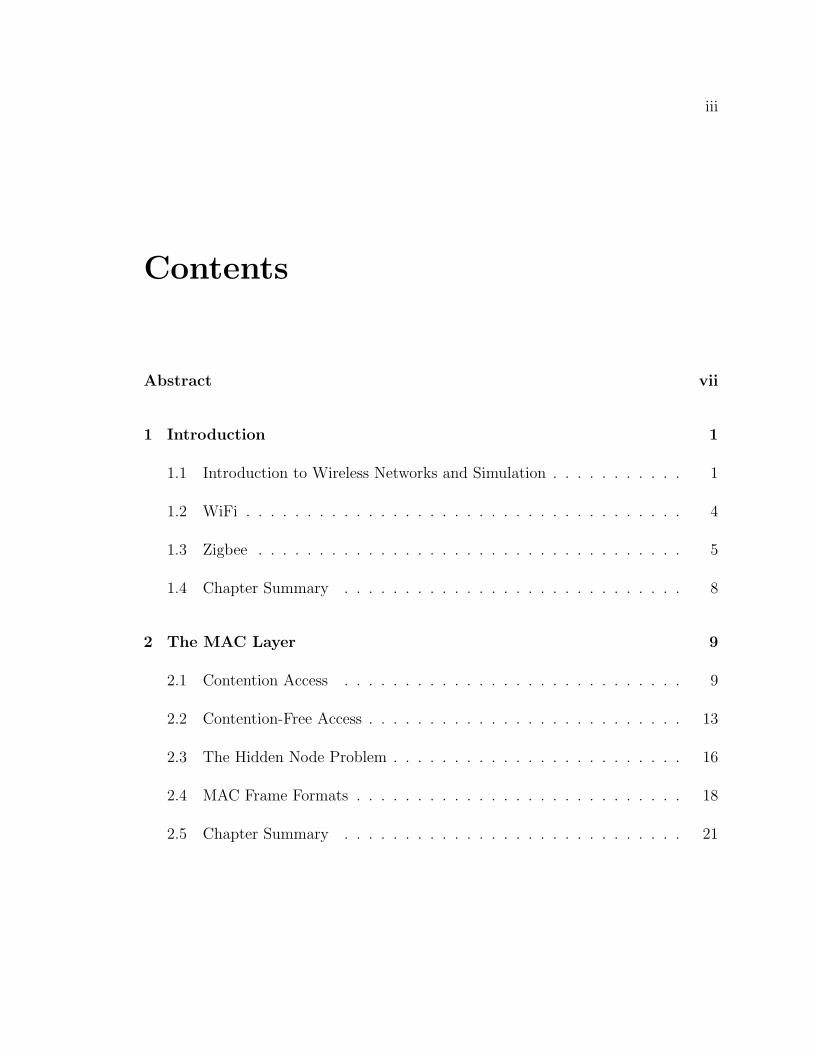
Contents
Abstract vii
1 Introduction 1
1.1 Introduction to Wireless Networks and Simulation . . . . . . . . . . . 1
1.2 WiFi . . . . . . . . . . . . . . . . . . . . . . . . . . . . . . . . . . . . 4
1.3 Zigbee . . . . . . . . . . . . . . . . . . . . . . . . . . . . . . . . . . . 5
1.4 Chapter Summary . . . . . . . . . . . . . . . . . . . . . . . . . . . . 8
2 The MAC Layer 9
2.1 Contention Access . . . . . . . . . . . . . . . . . . . . . . . . . . . . 9
2.2 Contention-Free Access . . . . . . . . . . . . . . . . . . . . . . . . . . 13
2.3 The Hidden Node Problem . . . . . . . . . . . . . . . . . . . . . . . . 16
2.4 MAC Frame Formats . . . . . . . . . . . . . . . . . . . . . . . . . . . 18
2.5 Chapter Summary . . . . . . . . . . . . . . . . . . . . . . . . . . . . 21
CONTENTS iv
3 The Physical Layer 22
3.1 Modulation and Data Rates . . . . . . . . . . . . . . . . . . . . . . . 23
3.2 Frequencies of Operation and Channels . . . . . . . . . . . . . . . . . 27
3.3 Range and Power . . . . . . . . . . . . . . . . . . . . . . . . . . . . . 30
3.4 PHY Packet Structure . . . . . . . . . . . . . . . . . . . . . . . . . . 33
3.5 Chapter Summary . . . . . . . . . . . . . . . . . . . . . . . . . . . . 36
4 Simulating Zigbee 37
4.1 Introduction to SWAN . . . . . . . . . . . . . . . . . . . . . . . . . . 37
4.2 From WiFi to Zigbee . . . . . . . . . . . . . . . . . . . . . . . . . . . 39
4.2.1 Power Model . . . . . . . . . . . . . . . . . . . . . . . . . . . 40
4.2.2 Bit Error Rate Model . . . . . . . . . . . . . . . . . . . . . . . 42
4.3 The ns-2 Implementation . . . . . . . . . . . . . . . . . . . . . . . . 43
4.4 Challenges in a SWAN Implementation . . . . . . . . . . . . . . . . . 44
4.4.1 Conflicting Data Types . . . . . . . . . . . . . . . . . . . . . . 44
4.4.2 Poor ns-2 IEEE 802.15.4 Documentation . . . . . . . . . . . . 46
4.4.3 Verification and Validation . . . . . . . . . . . . . . . . . . . . 46
4.5 Chapter Summary . . . . . . . . . . . . . . . . . . . . . . . . . . . . 47
5 Conclusion and Future Work 48

v
List of Figures
1.1 ISO/OSI Seven-Layer Networking Stack. . . . . . . . . . . . . . . . . 3
1.2 IEEE 802.11 Ad-hoc Network. . . . . . . . . . . . . . . . . . . . . . . 5
1.3 IEEE 802.11 Infrastructure Network. . . . . . . . . . . . . . . . . . . 6
1.4 IEEE 802.15.4 Peer-to-Peer Network. . . . . . . . . . . . . . . . . . . 7
2.1 IFS for Distributed Coordination Function and Point CoordinationFunction. . . . . . . . . . . . . . . . . . . . . . . . . . . . . . . . . . 11
2.2 GTS Allocation Method. . . . . . . . . . . . . . . . . . . . . . . . . . 15
2.3 The Hidden Node Problem Scenario. . . . . . . . . . . . . . . . . . . 17
2.4 IEEE 802.11 General MAC Frame. . . . . . . . . . . . . . . . . . . . 19
2.5 IEEE 802.15.4 General MAC Frame. . . . . . . . . . . . . . . . . . . 20
3.1 Simplified IEEE 802.11 FHSS Hopping Sequence. . . . . . . . . . . . 25
3.2 IEEE 802.11b CCK Bit Error Rates. . . . . . . . . . . . . . . . . . . 26
3.3 ISM Frequency Bands. . . . . . . . . . . . . . . . . . . . . . . . . . . 27
3.4 IEEE 802.11 DSSS PHY Channel Frequency Spacing . . . . . . . . . 28
3.5 IEEE 802.15.4 2.4Ghz PHY Channel Frequency Spacing . . . . . . . 29
3.6 Physical Layer State Machine. . . . . . . . . . . . . . . . . . . . . . . 31
3.7 IEEE 802.11 DSSS/IEEE 802.11b Long PPDU Frame Format . . . . 34
3.8 IEEE 802.15.4 2.4Ghz O-QPSK PPDU Frame Format . . . . . . . . . 35
4.1 Sample DML Configuration File. . . . . . . . . . . . . . . . . . . . . 38
4.2 The SWAN ProtocolSession API. . . . . . . . . . . . . . . . . . . . . 40
4.3 SWAN Code Showing Battery Consumption. . . . . . . . . . . . . . . 41
4.4 Simplified SWAN Code Showing Packet Acceptance. . . . . . . . . . 42
4.5 Comparison of SWAN and ns-2 Data Types . . . . . . . . . . . . . . 45

vii
Abstract
In the course of recent years, a new and exciting wireless network protocol hasemerged. The IEEE 802.15.4 standard provides the specification to build low-power,low-rate wireless network devices. This facilitates the creation of wireless sensor net-works (WSNs). WSNs can be used in many different scenarios ranging from farmingdata collection to home automation and security. As applications that use IEEE802.15.4 begin to become more prevalent, there is a tremendous research interest inthese networks.
In order to study IEEE 802.15.4 wireless networks and the scenarios it makespossible, simulation is very helpful. Simulation eliminates the need to set up a large-scale experiment and provides repeatable results. At Bucknell, we currently have ascalable network simulator, but it is only capable of simulating IEEE 802.11b wirelessnetworks. However, it is possible to develop a IEEE 802.15.4 model for the networksimulator. Not much is known about IEEE 802.15.4 in comparison with the widely-used and understood IEEE 802.11 WiFi standard for Wireless Area Networks. Thisthesis provides a comparison between the two wireless networking standards so thatone who knows WiFi well can understand easily how it differs from IEEE 802.15.4.The comparison will also serve to guide the creation of a simulation model for IEEE802.15.4.
1
Chapter 1
Introduction
The goal of this thesis is to compare, with an emphasis on simulation, two wire-less network protocols: WiFi, which is defined by the IEEE 802.11 specification andZigbee, which is defined by IEEE 802.15.4. Chapter 1 introduces the concept ofwireless networks and explains the different goals of IEEE 802.11 and IEEE 802.15.4wireless networks. Chapter 2 explains the medium access mechanisms of both stan-dards. Chapter 3 details the differences between IEEE 802.11 and IEEE 802.15.4with regards to radio characteristics. Chapter 4 describes simulator architecture andthe effort to port an existing IEEE 802.15.4 implementation to another simulator.Finally, Chapter 5 concludes the thesis with a road map to implementing Zigbee.
Note that for the purpose of this thesis, Zigbee and the IEEE 802.15.4 specificationare synonymous. The Zigbee standard actually refers to routing protocols outside thescope of this thesis, but Zigbee devices rely on the IEEE 802.15.4 specification.
1.1 Introduction to Wireless Networks and Simu-
lation
Wireless networking has increased the level of mobility, convenience, and productivityof computers and technology. It has allowed laptops to connect to the Internet fromanywhere in the vicinity of an access point or other computer. Wireless headsetscan now communicate with cell phones to provide a safer way to drive a vehicle.
CHAPTER 1. INTRODUCTION 2
Additionally, a network of low-powered devices can be used to collect data wherewires would make it difficult or impossible. These networks had to be studied beforethey could become mainstream technology.
Directly studying wireless networks is a challenging task for two reasons. First, theconditions surrounding the experiment can never be fully controlled and are thereforenot repeatable. Second, it is difficult to manage (and pay for) a large-scale experi-ment with many human-operated hardware devices. Instead, a model can be builtin software to replicate the behavior of a real network. A high-performance com-puter simulation that uses these models allows for fully controllable experiments withrepeatable results. Since networking hardware is not required, simulations can beconducted at low cost and still yield results that can predict or estimate the metricsof the real system (Liu et al. 2001).
Three metrics are commonly used to characterize the performance of wirelessnetworks. First, the packet delivery ratio is used to indicate the success rate oftransmitting data. It is the percentage of packets received relative to the numberof packets sent. Since packets can be lost in a variety of ways during transmission,this is an important metric. Second, the time delay between sending and receiving apacket represents the network latency. It is desirable to minimize the network latencyto improve the response time of network applications. For example, low latency isimportant for voice chat or online gaming. Last, the amount of overhead traffic neededfor network maintenance and routing is used to indicate the efficiency of the network.A network that has too much control traffic will reduce the available bandwidth fordata (Perrone and Nelson 2006).
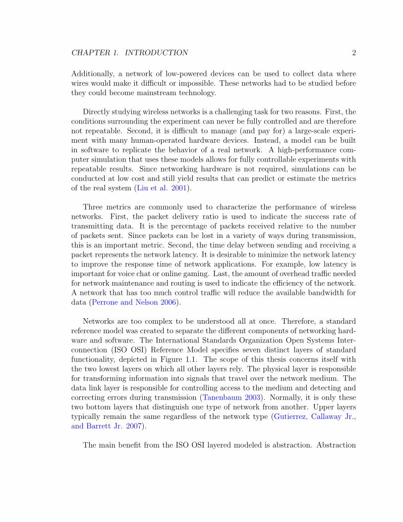
Networks are too complex to be understood all at once. Therefore, a standardreference model was created to separate the different components of networking hard-ware and software. The International Standards Organization Open Systems Inter-connection (ISO OSI) Reference Model specifies seven distinct layers of standardfunctionality, depicted in Figure 1.1. The scope of this thesis concerns itself withthe two lowest layers on which all other layers rely. The physical layer is responsiblefor transforming information into signals that travel over the network medium. Thedata link layer is responsible for controlling access to the medium and detecting andcorrecting errors during transmission (Tanenbaum 2003). Normally, it is only thesetwo bottom layers that distinguish one type of network from another. Upper layerstypically remain the same regardless of the network type (Gutierrez, Callaway Jr.,and Barrett Jr. 2007).
The main benefit from the ISO OSI layered modeled is abstraction. Abstraction

CHAPTER 1. INTRODUCTION 3
Application
Network
Presentation
Session
Transport
Data Link
Physical
Defined in Wireless Standards
Figure 1.1: ISO/OSI Seven-Layer Networking Stack.
hides the specific details of each layer’s behaviors. This results in interoperabilityand flexibility between layers. Since the interfaces between layers are fixed, a layercan be swapped out with a different implementation and everything will still work.For example, the Medium Access Control (MAC) and Physical (PHY) layers can beimplemented as either a wired or wireless protocol. The next layer above (Network)will function with either the wired or wireless implementation.
Wireless networks can be partitioned into two main classifications: Wireless LocalArea Networks (WLANs) and Wireless Personal Area Networks (WPANs). WLANsoften provide fast access to the Internet and other resources. They offer high-rate data
CHAPTER 1. INTRODUCTION 4
transfer over an average distance of about 300 ft. On the other hand, WPANs providenetworking on short distances of about 30 ft and at lower data rates. Since they arelimited in bandwidth and range, their power consumption and cost is minimized(Cooklev 2004).
1.2 WiFi
The IEEE 802.11 standard defines the WiFi specification. WiFi was created to elim-inate the main disadvantages of local area networks: wires. Although Ethernet was asuccess, it required special networking cables to be installed from computer to com-puter. A wireless implementation of Ethernet would solve this problem. As a result,the IEEE 802.11 WiFi standard was created (Cooklev 2004).
Different physical layers exist for IEEE 802.11 wireless networking. Each physicallayer will have unique power requirements, signal range, and bandwidth specifica-tions. For example, the IEEE 802.11b physical layer has a maximum throughput of11 megabits per second (Mbps) and has a range between 150-1000ft depending onenvironmental conditions with a frequency of 2.4GHz. The bandwidth was increasedto 54 Mbps with IEEE 802.11g, which uses a different physical layer and a modifiedMAC layer to ensure backwards compatibility with IEEE 802.11b (Cooklev 2004).
There are two main types of network architectures described in the IEEE 802.11standard. The first is an Independent Basic Service Set (IBSS). Using this structure,network devices communicate ad-hoc, without infrastructure and independent of acentral authority. Decision making (e.g., when a device should transmit) for thenetwork is based on distributed algorithms that work across the IBSS. All the deviceshave the same responsibilities and the network is typically short-lived. Any devicecan connect and disconnect from an IBSS without major disruption since the networkis self-adjusting. Figure 1.2 depicts the structure of an ad-hoc wireless network wherethe squares represent wireless devices (Cooklev 2004).
The second type of network architecture is a Basic Service Set (BSS). In thismodel, a single Access Point (AP) device is responsible for decision making. Multipledevices can connect and communicate with the AP, but not with each other. The APis usually connected to an additional wired network to join two networks together.For instance, an AP connected to a broadband modem is a very common scenario.BSSs are more permanent than an IBSS since the AP must be established and always

CHAPTER 1. INTRODUCTION 5
Figure 1.2: IEEE 802.11 Ad-hoc Network.
available, which improves network reliability. Figure 1.3 depicts the structure ofseveral infrastructure wireless networks with a common wired backbone (Cooklev2004).
Whereas the goal of WiFi was to make Ethernet wireless, WPAN wireless tech-nologies seek to create small, low-power networks for devices to communicate. Oneof these WPAN standards, Zigbee, is introduced in the next section.
1.3 Zigbee
The IEEE 802.15.4 standard defines the Zigbee specification. This protocol is in-tended for use with extremely low-powered devices, short transmission distances upto about 30 ft, and low data rates up to about 250 kilobits per second. The primaryapplication of Zigbee is to create Wireless Sensor Networks (WSNs), which are usedto decrease the cost of installing sensors, avoid the problems caused with cable con-nections, and decrease the complexity of the network (Gutierrez, Callaway Jr., andBarrett Jr. 2007).
Since the specific applications of Zigbee and WSNs are probably less familiar toconsumers than WiFi, it is helpful to illustrate with examples. A sensor networkfor home automation could be deployed to monitor temperature readings in different

CHAPTER 1. INTRODUCTION 6
AP AP AP
wired backbone
Figure 1.3: IEEE 802.11 Infrastructure Network.
rooms and adjust the thermostat accordingly. Wireless smoke detectors and burglarintrusion sensors could interact with a home security system. A WSN could alsobe used to increase the efficiency of farming by creating a self-organizing network totake soil readings and other statistics across large fields. Additionally, small wirelessgadgets such as remote controls and toys can take advantage of the low cost andpower demands of Zigbee (Gutierrez, Callaway Jr., and Barrett Jr. 2007).
The network architecture specified by IEEE 802.15.4 is very different from theIEEE 802.11 architecture. Devices on a Zigbee network can have one of three dif-ferent roles. The first is the Personal Area Network (PAN) Coordinator. The PANCoordinator is responsible for the general management of the network. It is in controlof the type of network and responsible for allowing other devices to join the network.The second type of role is a coordinator. Coordinators can forward messages to othernodes and act as a proxy to the PAN Coordinator for nodes that are out of range. Thelast type of role is called a network device. A IEEE 802.15.4 network exists whenthere is exactly one PAN coordinator and at least one network device (Gutierrez,Callaway Jr., and Barrett Jr. 2007).
While there are three different types of roles a device may serve, there are twodifferent physical device types. The first type of device is a Full Function Device(FFD). FFDs are fully capable of all MAC services and can serve any of the threeroles. The second type is a Reduced Function Device (RFD). RFDs are only capable ofbecoming a network device. They were designed to allow for the creation of extremelylow-powered devices that were not required to forward messages or perform any othercomplex or unnecessary power consuming tasks (Gutierrez, Callaway Jr., and Barrett
CHAPTER 1. INTRODUCTION 7
Jr. 2007).
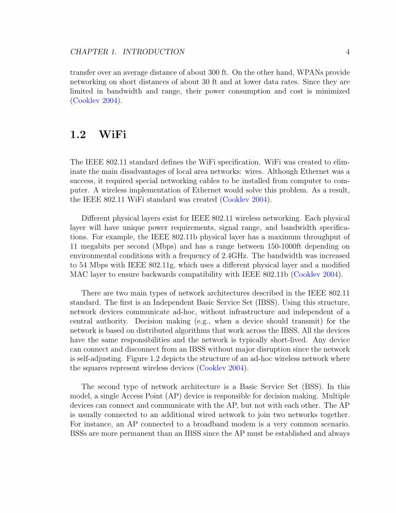
Two network topologies are supported by Zigbee. The star network topology ischaracterized by a central PAN Coordinator that can directly communicate with everyother node. Other network devices can only communicate with the PAN Coordinator.The peer-to-peer network topology consists of a single PAN Coordinator and othercoordinators or network devices. As long as they are within range, devices maycommunicate with each other without the direct involvement of the PAN Coordinator.The peer-to-peer network is depicted in Figure 1.4 (IEEE 802.15.4 2006).
PAN Coordinator
Coordinator
Network Device
Figure 1.4: IEEE 802.15.4 Peer-to-Peer Network.
CHAPTER 1. INTRODUCTION 8
1.4 Chapter Summary
In this chapter, the importance of wireless networks and why it is useful to simulatethem was discussed. Additionally, the basic network topologies of both WiFi andZigbee were presented. WiFi has two modes of operation: as a BSS, and an IBSS.BSSs have a central device to manage the network whereas IBSSs form a distributed,ad-hoc network. Zigbee also has two similar network structures: star and peer-to-peer. However, both network formations need a central PAN Coordinator to managethe network.
In the next chapter, the MAC layers of WiFi and Zigbee are examined.
9
Chapter 2
The MAC Layer
Several issues arise using a broadcast medium such as wireless where all nodes shareaccess to the network simultaneously. Consider a room full of people who always havesomething to say to everyone else. If everybody started talking at the same time, itwould be impossible to listen to what individual people have to say. Therefore, therestriction must be imposed that only one person may talk at a time. But who decideswhich person should talk at a given time? How is that person chosen? And once themessage is sent, did everybody hear the message correctly?
Essentially, this is the problem the Medium Access Control (MAC) layer solves(Tanenbaum 2003). By imposing strict regulations on when a wireless device cansend data across the shared medium, the chance that another transmitting devicewill interfere is reduced.
Each wireless standard has its own MAC layer. While their goals are relativelythe same (controlling access to the airwaves), they often achieve them using differentmeans.
2.1 Contention Access
Contention access is a mechanism by which different nodes compete with each otherin order to use the shared medium. In the case of the room of people, this will

CHAPTER 2. THE MAC LAYER 10
involve a set of policies that dictate when a person can begin to talk. For instance, aperson may talk if no other person is currently talking. Contention access is a formof distributed decision-making.
WiFi
The Distributed Coordination Function (DCF) is responsible for deciding when awireless device can transmit on the medium when multiple stations are competingto transmit. The basic mechanism for arbitrating channel access in the IEEE 802.11standard is Carrier-Sense Multiple Access with Collision Avoidance (CSMA/CA) andExponential Backoff. Simply put, this method requires devices that have data totransmit to first listen for an open channel. Unlike wired devices, most wirelessdevices cannot send and receive at the same time, so collisions cannot be detectedby transmitting stations. If no other devices are transmitting during some interval oftime before some device wishes to transmit, there is a good chance no other devicewill start to transmit as well and distort the signal (O’Hara and Petrick 2005).
Timing is essential for CSMA/CA to work. Several different timing intervals aredefined by the standard. The Interframe Space (IFS) is the time between frames.Short IFS (SIFS) is fixed by the physical layer and represents the time needed forthe device to switch between send and receive mode. The Point IFS (PIFS) is SIFSplus the time to detect an open channel, switch modes, MAC processing, and airpropagation. The sum of those is known as the slot time. The Distributed IFS(DIFS) is the SIFS plus two slots times. The relationship between DIFS and PIFS isillustrated in Figure 2.1. And the Extended IFS (EIFS) is the sum of the SIFS, DIFS,and the time needed to transmit an acknowledgment frame. If the wireless mediumhas been idle for a period of time equal to the DIFS, the device will pass the physicalchecking mechanism. If the previous frame received had an error, the interval mustbe equal to the EIFS. (Cooklev 2004).
In addition to physically listening for use of the medium before transmissions, avirtual carrier sense mechanism is also used. Each device has a special variable calleda network allocation vector (NAV) to decide if the medium is busy. All frames thatare sent wirelessly contain duration information on how long the frame will take totransmit. The NAV is updated with the duration information to specify the amountof time that must pass before the medium could be idle (O’Hara and Petrick 2005).The NAV value is continuously decremented through time. When the NAV reaches avalue of zero, the virtual carrier sense mechanism reports the medium as free (IEEE

CHAPTER 2. THE MAC LAYER 11
Previous Frame Received Frame to Transmit
DIFS
Time
Previous Frame Received Frame to Transmit
PIFS
Figure 2.1: IFS for Distributed Coordination Function and Point Coordination Function.
802.11 2007).
When the MAC layer receives data to transmit from a higher layer in the network-ing stack, these two mechanisms are checked to attempt to avoid a collision on thewireless medium. If both indicate the medium should be free, a MAC frame is createdand sent to physical layer for transmission. However, if one or both checks fail, thedevice does not transmit and the backoff algorithm is triggered. The algorithm isalso triggered if the frame was sent, but an acknowledgment was not received by thedestination device.
The backoff algorithm first increments a retry counter for the frame being trans-mitted. There are two different retry counters: one for long frames and one for shortframes. After the correct retry counter is incremented, a random number is selectedwithin a range called the Contention Window (CW). The CW represents the amountof time the medium must be idle before attempting transmission again. Each timethe frame fails to transmit, the CW is doubled. The minimum and maximum valuesfor the CW are specific to each physical layer (O’Hara and Petrick 2005).
CHAPTER 2. THE MAC LAYER 12
Zigbee
Like IEEE 802.11, the IEEE 802.15.4 standard also uses CSMA-CA to regulate accessto the wireless medium during a contention access period (Gutierrez, Callaway Jr.,and Barrett Jr. 2007). However, two different types of CSMA-CA are used: slottedand unslotted. Slotted CSMA-CA is used in beacon-enabled networks and unslottedCSMA-CA is used in non-beacon-enabled networks. While the basic idea of thealgorithms are the same, they differ in the timing details (IEEE 802.15.4 2006).
Slotted CSMA-CA is used when beacons are used by coordinators to synchronizecommunications in the network. Each period of time between beacons is subdividedinto 16 time slots. As described previously, CSMA-CA generates random backoffintervals to aid in avoiding collisions in the air. Slotted CSMA-CA mandates thatthe backoff intervals directly align with the beginning of one of the 16 time slots.A contention window is also used for the slotted algorithm. The contention windowrepresents the number of time slots that must pass with idle wireless activity tobegin a transmission. The window is initialized at two and is decremented each timethe channel is assessed to be free. When the window value reaches zero, the devicemay begin transmission. Each time the medium is determined to be in use, thewindow is reset to its initial value of two and continues until the maximum numberof transmission attemps occurs (IEEE 802.15.4 2006).
Unslotted CSMA-CA is used in networks without beacons. Clearly, there is norequirement for backoff intervals to be aligned to slots since there are no time slots. Aswith slotted-CSMA the backoff interval increases each time a clear channel assessmentfails (IEEE 802.15.4 2006).
The unslotted algorithm most closely compares with the CSMA-CA algorithmdefined in IEEE 802.11. The terminology is slightly different, though. The contentionwindow in IEEE 802.11 is similar to the backoff periods of IEEE 802.15.4. They bothrepresent the amount of time required before a clear channel assessment is attemptedagain.
CHAPTER 2. THE MAC LAYER 13
2.2 Contention-Free Access
Contention-free access is noncompetitive mechanism to use a shared medium. In theroom of people, contention-free access could involve electing one person to act as aleader who tells each person when he can talk. Contention-free access can be usefulif applications need a guaranteed quality of service or have low-latency requirements(Gutierrez, Callaway Jr., and Barrett Jr. 2007).
WiFi
The Point Coordination Function (PCF) is responsible for controlling contention-freeaccess to the wireless medium. This is accomplished through the use of a singleAccess Point (AP) with which all devices can communicate. During a contention-freeperiod, the AP has complete control over all wireless activity and no other devicemay interrupt. It follows a basic “speak only if spoken to rule” (O’Hara and Petrick2005).
The series of events leading up to and during a contention-free period is as follows.First, devices must register with the AP in order to request contention-free access tothe medium. This is necessary so the AP can maintain a list of devices to poll.Next, the AP must gain sole access to the medium. It accomplishes this throughthe contention access protocol described previously (the DCF) (O’Hara and Petrick2005). As a result, the length of the contention-free period might be shortened (IEEE802.11 2007). However, the AP has an advantage: the Point Interframe Space timinginterval is shorter than the Distributed Interframe Space interval. Therefore, the AP(when beginning a contention-free period) has priority access to the medium (O’Haraand Petrick 2005).
When the AP has control, it sends a beacon to indicate to all other stations thata contention-free period has begun. This is the primary mechanism to ensure thatno other devices will attempt to transmit during this time. The beacon contains themaximum expected length of the contention-free period, so all NAVs can be updatedto reflect this. If a device attempts to transmit, it will fail the virtual carrier sensingmechanism. Additionally, since the PIFS is shorter than the DIFS, devices usingCSMA-CA will not have the opportunity to transmit since they must wait longer.This is a backup method in case a device did not receive the beacon. To bringthis about, the AP will always transmit within the PIFS time during contention-free
CHAPTER 2. THE MAC LAYER 14
access. (O’Hara and Petrick 2005).
Devices must first register with the AP in order to be placed on a polling list.While it is not mandatory to use a contention-free period, all network stations mustbe able to recognize it is occurring and not conduct normal CSMA-CA operations.When a device is polled by AP to check if there is data to transmit, the device maytransmit zero or one data frames in response. In order to increase efficiency, it is alsopossible for data delivered by the AP to a device to contain a poll request (O’Haraand Petrick 2005).
The AP will end a contention-free period by transmitting a MAC control frame in-dicating such. When received, all wireless devices can update their NAVs accordingly(O’Hara and Petrick 2005).
Zigbee
Much like an access point, the PAN coordinator is responsible for managing contention-free periods on a IEEE 802.15.4 beacon-enabled network. As previously described,16 time slots are allocated between beacons. Some of these time slots can be directlyallocated to a specific device. These slots are called Guaranteed Time Slots (GTS)and serve as mechanism to enable contention-free access (Gutierrez, Callaway Jr.,and Barrett Jr. 2007).
Guaranteed Time Slots are only managed and used by the PAN coordinator ofthe network. Therefore, only devices that are in range and associated with the PANcoordinator may take advantage of GTSs. A Guaranteed Time Slot may extend overmultiple slots of the 16 time slots in between beacons. A maximum of seven GTSsare permitted between beacons. Requests from devices for GTSs are handled with afirst-come-first-served policy. The GTSs are required to be allocated in the slots afterthe contention-access period (IEEE 802.15.4 2006).
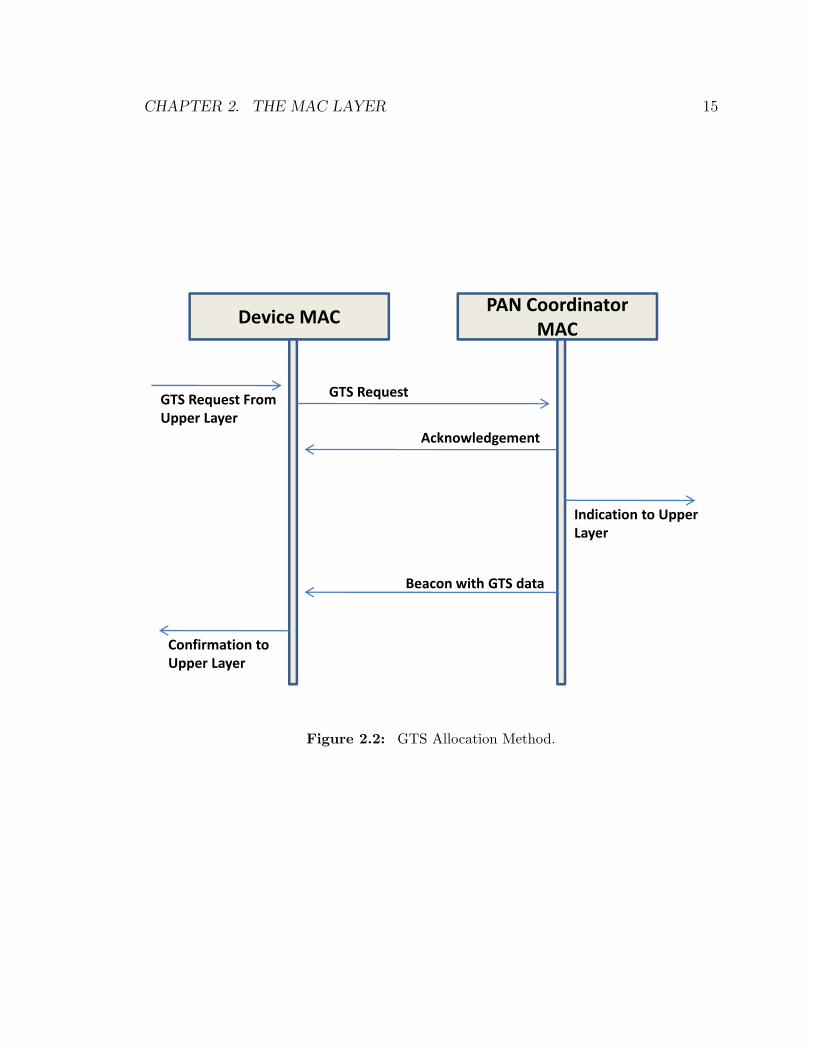
Devices can request GTSs using the mechanism pictured in Figure 2.2. A GTSrequest message is generated by a device and sent to the PAN coordinator. ThePAN coordinator sends back an acknowledgment indicating the request was received.Some time after, a regular beacon frame is sent by the PAN coordinator. The beaconcontains information about the Guaranteed Time Slots, so the device that requestedthe contention-free access can check if the request was granted (Gutierrez, CallawayJr., and Barrett Jr. 2007).
CHAPTER 2. THE MAC LAYER 15
GTS Request FromUpper Layer
GTS Request
Device MACPAN Coordinator
MAC
Acknowledgement
Indication to Upper Layer
Beacon with GTS data
Confirmation toUpper Layer
Figure 2.2: GTS Allocation Method.

CHAPTER 2. THE MAC LAYER 16
The deallocation of GTSs can be initiated by either the device that requestedthe service or the PAN coordinator. In either case, after the GTS is released, thedevice still has the opportunity to communicate during the contention-access period.After several allocations and deallocations, it is possible for gaps to emerge betweenassigned GTSs. The PAN coordinator has the responsibility of removing the gaps(Gutierrez, Callaway Jr., and Barrett Jr. 2007).
2.3 The Hidden Node Problem
The CSMA-CA protocol works well when all devices are within range of one another.However, consider the scenario presented in Figure 2.3. It consists of three devices,two of which (A and C) attempt to send data to the third (B). Devices A and C arealso not in range of each other.
Since Device A is out of range of Device C, it will never be able to detect atransmission from Device C (O’Hara and Petrick 2005). Therefore, the CSMA-CAprotocol will not be effective if Device A attempts to transmit to Device B if DeviceC is also transmitting at the same time. The physical carrier sensing mechanism ofDevice A will report the wireless medium is free, when in fact it is in use near DeviceB. As a result, the two signals will collide and Device B will not be able to decipherthe message (O’Hara and Petrick 2005).
Note that if contention-free access is used by Devices A and C to communicatewith Device B, this problem would not occur. With WiFi, the AP would poll DevicesA and B at different times and avoid a collision. With Zigbee, the devices would havetheir own Guaranteed Time Slots for transmission which would also avoid a collision.
The IEEE 802.11 standard for WiFi mitigates the hidden node problem by in-troducing small Request to Send (RTS) and Clear to Send (CTS) control messages.Before a device transmits data, it will first send a RTS message to the destinationdevice. The destination will then send a CTS message back (O’Hara and Petrick2005). However, the CTS is sent only if the NAV of the destination indicates themedium is free. Otherwise the CTS message will not be sent. The source will waitfor a certain amount of time to pass to receive the CTS message. If the message isnot received, the backoff algorithm is triggered (IEEE 802.11 2007).

CHAPTER 2. THE MAC LAYER 17
AB
C
Figure 2.3: The Hidden Node Problem Scenario.
This exchange informs other devices in the vicinity of both the source and des-tination that the medium will be in use. When a device (that isn’t the destination)receives a RTS frame, it will not use the medium until the requested frame is sent bythe source. When a device receives a CTS frame, it will not use the medium untilthe acknowledgment is sent by the destination (O’Hara and Petrick 2005).
Clearly, this method to solve the hidden node problem introduces some overheadwith the RTS and CTS messages. Therefore, the IEEE 802.11 standard allows fora minimum frame size threshold for the RTS/CTS procedure to be configured. Anyframes of size less than the threshold will not be proceeded with a RTS frame. Thisenables network administrators to set an appropriate threshold based on the specificnetwork geography, the prevalence of hidden nodes, and the data rate of the physicallayer (O’Hara and Petrick 2005).
The IEEE 802.15.4 standard does not contain a solution to the hidden node prob-lem; it ignores it. To keep things simple by reducing control overhead and savingbattery life, the RTS/CTS method is not used (Hwang et al. 2005). As such, Zigbeeis prone to many collisions and performance degradation due to hidden nodes. How-ever, it is still possible to reduce the impact of hidden nodes by configuring network

CHAPTER 2. THE MAC LAYER 18
settings. For instance, increasing the signal power of nodes will enable detection oftransmissions (from a clear channel assessment) from a further distance. In beacon-enabled networks, increasing the time between beacons can also reduce collisions fromhidden nodes (Harthikote-Matha, Banka, and Jayasumana 2007).
2.4 MAC Frame Formats
The different types of MAC Frame Formats for WiFi and Zigbee are discussed in thissection.
WiFi
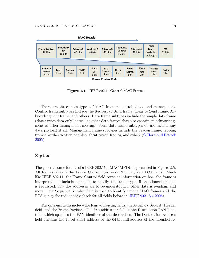
The IEEE 802.11 MAC accepts MAC Service Data Units (MSDUs) from upper layersin the networking stack. Headers and trailers are added by the MAC layer to formMAC Protocol Data Units (MPDUs) which are then passed to the physical layer fortransmission. These MPDUs are called MAC frames. The general MAC frame ispresented in Figure 2.4 (O’Hara and Petrick 2005).
All MAC frames contain the first three and the last field of the general frame.This includes the Frame Control, Duration/ID, Address 1, and the FCS fields. TheFrame Control field specifies the protocol version, frame type, retry status, powermanagement status, and other information. The purposes of the Duration/ID andAddress 1 fields change based on the frame type, and the FCS is a cyclic redundancycheck sequence to make sure all other fields in the frame were correctly transmitted(IEEE 802.11 2007).
The optional fields include three additional address fields, the Sequence Controlfield, and the Frame Body. Each address field can contain one of five address types:the transmitter address, receiver address, source address, destination address, or theBSSID. The Sequence Control field can be used to eliminate duplicate frames sentto a wireless device. The Frame Body is the first field that is not part of the MACheader and represents the actual payload. It has a variable length up to 2304 byteswithout WEP encryption or 2312 bytes with WEP encryption (O’Hara and Petrick2005).
CHAPTER 2. THE MAC LAYER 19
MAC Header
Frame Control Field
Protocol Version
2 bits
Type2 bits
Subtype
2 bitsTo DS1 bit
From DS
1 bit
More Fragments
1 bit
Retry1 bit
Power Mgmt.
1 bit
More Data1 bit
Protected Frame
1 bit
Order1 bit
Frame Control16 bits
Duration/ID
16 bits
Address 148 bits
Address 248 bits
Address 348 bits
SequenceControl16 bits
Address 448 bits
Frame Body
Variablebit length
FCS32 bits
Figure 2.4: IEEE 802.11 General MAC Frame.
There are three main types of MAC frames: control, data, and management.Control frame subtypes include the Request to Send frame, Clear to Send frame, Ac-knowledgment frame, and others. Data frame subtypes include the simple data frame(that carries data only) as well as other data frames that also contain an acknowledg-ment or other management message. Some data frame subtypes do not include anydata payload at all. Management frame subtypes include the beacon frame, probingframes, authentication and deauthentication frames, and others (O’Hara and Petrick2005).
Zigbee
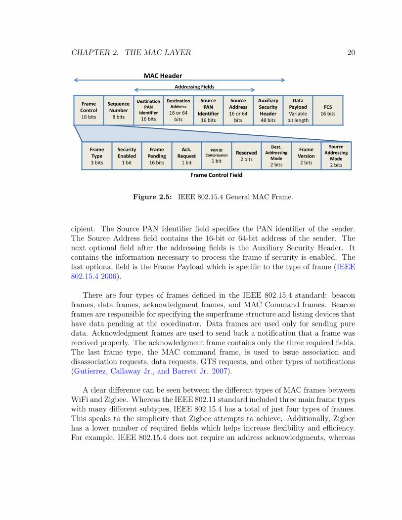
The general frame format of a IEEE 802.15.4 MAC MPDU is presented in Figure 2.5.All frames contain the Frame Control, Sequence Number, and FCS fields. Muchlike IEEE 802.11, the Frame Control field contains information on how the frame isinterpreted. It includes subfields to specify the frame type, if an acknowledgmentis requested, how the addresses are to be understood, if other data is pending, andmore. The Sequence Number field is used to identify unique MAC frames and theFCS is a cyclic redundancy check for all fields before it (IEEE 802.15.4 2006).
The optional fields include the four addressing fields, the Auxiliary Security Headerfield, and the Frame Payload. The first addressing field is the Destination PAN Iden-tifier which specifies the PAN identifier of the destination. The Destination Addressfield contains the 16-bit short address of the 64-bit full address of the intended re-
CHAPTER 2. THE MAC LAYER 20
MAC Header
Frame Control16 bits
Sequence Number
8 bits
Destination PAN
Identifier
16 bits
Destination Address
16 or 64 bits
Source PAN
Identifier16 bits
Source Address16 or 64
bits
Auxiliary Security Header48 bits
Data PayloadVariable
bit length
FCS16 bits
Addressing Fields
Frame Type3 bits
SecurityEnabled
1 bit
Frame Pending16 bits
Ack.Request
1 bit
PAN ID Compression
1 bit
Reserved2 bits
Dest. Addressing
Mode
2 bits
Frame Version2 bits
Source Addressing
Mode
2 bits
Frame Control Field
Figure 2.5: IEEE 802.15.4 General MAC Frame.
cipient. The Source PAN Identifier field specifies the PAN identifier of the sender.The Source Address field contains the 16-bit or 64-bit address of the sender. Thenext optional field after the addressing fields is the Auxiliary Security Header. Itcontains the information necessary to process the frame if security is enabled. Thelast optional field is the Frame Payload which is specific to the type of frame (IEEE802.15.4 2006).
There are four types of frames defined in the IEEE 802.15.4 standard: beaconframes, data frames, acknowledgment frames, and MAC Command frames. Beaconframes are responsible for specifying the superframe structure and listing devices thathave data pending at the coordinator. Data frames are used only for sending puredata. Acknowledgment frames are used to send back a notification that a frame wasreceived properly. The acknowledgment frame contains only the three required fields.The last frame type, the MAC command frame, is used to issue association anddisassociation requests, data requests, GTS requests, and other types of notifications(Gutierrez, Callaway Jr., and Barrett Jr. 2007).
A clear difference can be seen between the different types of MAC frames betweenWiFi and Zigbee. Whereas the IEEE 802.11 standard included three main frame typeswith many different subtypes, IEEE 802.15.4 has a total of just four types of frames.This speaks to the simplicity that Zigbee attempts to achieve. Additionally, Zigbeehas a lower number of required fields which helps increase flexibility and efficiency.For example, IEEE 802.15.4 does not require an address acknowledgments, whereas

CHAPTER 2. THE MAC LAYER 21
IEEE 802.11 requires the address of the recipient. This is eliminated in Zigbee sincethe Sequence Number field is adequate enough to process an acknowledgment.
2.5 Chapter Summary
In this chapter, the different mechanisms by which WiFi and Zigbee arbitrate chan-nel access were examined. The contention access mechanisms of both protocols useCSMA/CA to detect when the medium is busy. However, Zigbee offers slotted andunslotted CSMA/CA depending on beaconed or beaconless operation. Additionally,both standards support contention-free access. In WiFi networks, APs act as a centralarbitrator whereas PAN coordinators fill that role in Zigbee networks. The hiddennode problem was also examined with regards to IEEE 802.11 and IEEE 802.15.4networks. WiFi directly addresses the problem of hidden nodes by introducing RTSand CTS messages, while Zigbee ignores the problem completely. Finally, the frameformats of the two protocols were examined.
In the next chapter, the physical layer of WiFi and Zigbee is examined. Thephysical layer is directly below the MAC layer and completes the set of differencesbetween the two protocols.

22
Chapter 3
The Physical Layer
The physical layer is at the bottom of the ISO/OSI seven-layer networking stack.It is responsible for converting the binary data received from the MAC layer intoelectromagnetic or optical signals for transmission over the medium. For wirelessmedia, the physical layer is constrained to operate in portions of the electromagneticspectrum defined by regulatory bodies and to operate in specific ways. In the UnitedStates, for example, the Federal Communications Commission oversees the allocationof the spectrum.
The original IEEE 802.11 specification defined three distinct physical layers. Oneof them is for infrared communication and is beyond the scope of this thesis. The othertwo, which are a Direct Sequence Spread Spectrum (DSSS) PHY and a FrequencyHopping Spread Spectrum (FHSS) PHY, represent different ways to handle wirelesscommunication. The now common IEEE 802.11a, IEEE 802.11b, and IEEE 802.11gextensions to the standard were adopted after publication of the IEEE 802.11 stan-dard (O’Hara and Petrick 2005). More attention will be given to the IEEE 802.11bstandard, but discussion of the original DSSS and FHSS PHYs and IEEE 802.11gwill also be included.
The IEEE 802.15.4 standard defines four physical layers. Two additional physicallayers are defined in IEEE 802.15.4a.
In the remainder of this chapter, the two standards are compared based on howthey deal with modulation, data rates, use of the electromagnetic spectrum, range ofsignal propagation, transmission power, and the structure of the PHY layer’s protocol
CHAPTER 3. THE PHYSICAL LAYER 23
data unit.
3.1 Modulation and Data Rates
The process of modulation involves converting source data to a form that can betransmitted over a physical medium. For digital communications, modulation canalso be viewed as transforming binary data to a signal that can be sent by onewireless device and received by another (Rappaport 1996).
WiFi
Spread spectrum is a type of modulation to increase the signal-to-noise ratio byspreading the signal across many different frequencies. By allowing the signal to spanmultiple frequencies, the impact of possible of a narrow frequency band of interfer-ence. Spread spectrum techniques are used in the original DSSS and FHSS physicallayers. The DSSS method translates individual bits (zeros or ones) into a sequenceof bits called chipping codes. For instance, a binary 1 is converted to 0010011100 fortransmission. Through this translation, the radio is able to operate with more outsideinterference since the chipping code can be heard more clearly (Geier 1999).
Consider the following example to show how chipping codes can increase the signal-to-noise ratio. The words “yes” and “no” are short and can be easily misheard. If thechipping code of “yes, you are right” is assigned to “yes” and “no, you are wrong” isassigned to “no”, it would be easier to distinguish between the two words “yes” and“no” in a loud room. There is simply more data to decide which word was heard.The same is applied to binary ones and zeros.
The DSSS PHY of IEEE 802.11 is capable at transmitting at data rates of 1Mbpsor 2Mbps. In order to achieve the different data rates, different modulation techniquesare used, both a form of differential phase-shift keying, which is beyond the scope ofthis thesis (Cooklev 2004).
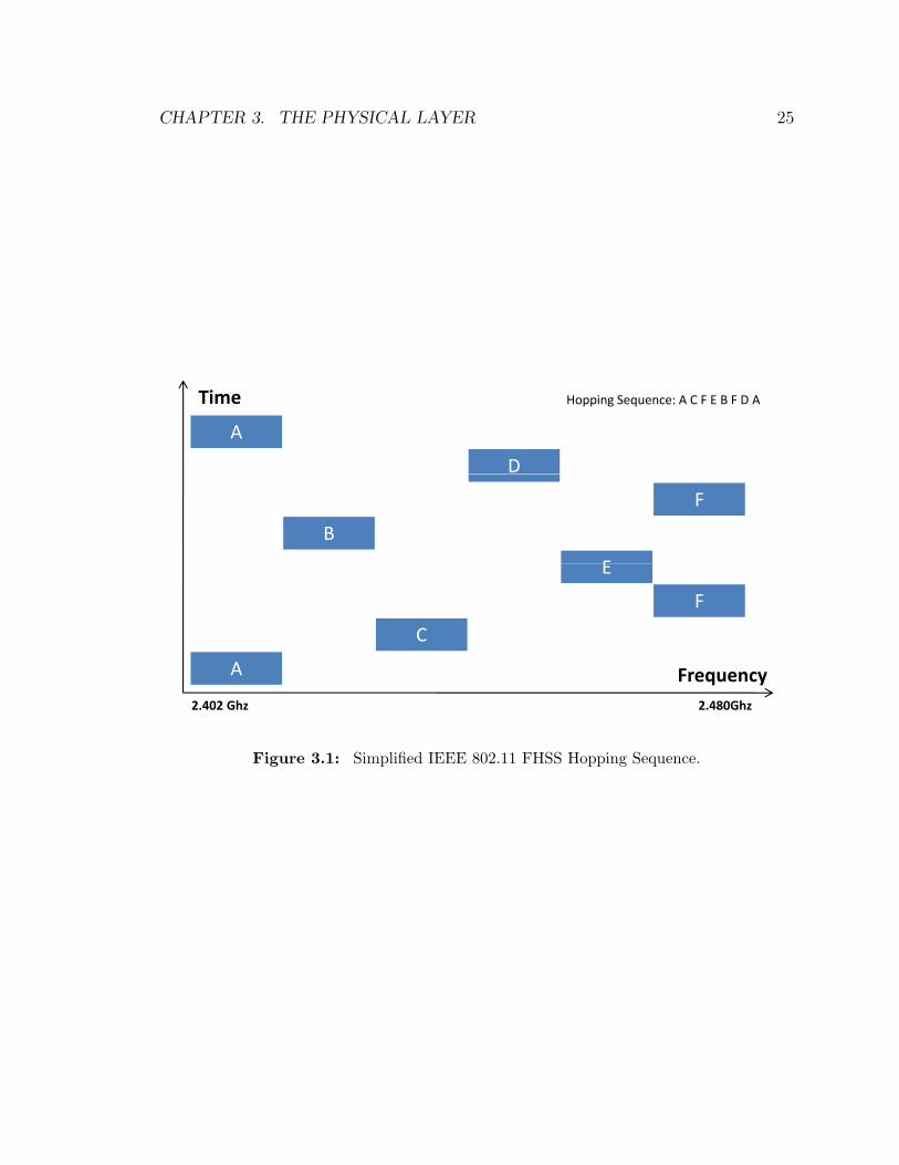
The IEEE 802.11 standard also defines a Frequency Hopping Spread Spectrum(FHSS) physical layer. Using this method, the signal is spread by periodically chang-ing the broadcast radio frequency. This increases the signal-to-noise ratio by using a
CHAPTER 3. THE PHYSICAL LAYER 24
different frequencies. If there is interference on one frequency, only a small fraction oftime will be used to transmit on that frequency before it is changed again. A hoppingcode specifies which frequencies will be used and their sequence. This allows differentstations using FHSS to share the same central frequency, but use a different hoppingcode to avoid interference with each other. A device wishing to receive the signalmust use the same hopping code as the sender (Geier 1999).
Figure 3.1 depicts how frequency hopping works for IEEE 802.11. However, thefigure has been greatly simplified since there are 79 distinct channels of 1Mhz widthin the 2.4Ghz band and it does not represent any defined IEEE 802.11 hopping code.Like the DSSS PHY, the PHSS PHY can transmit at data rates of 1Mbps or 2Mbps(O’Hara and Petrick 2005).
In addition to the three original PHYs defined in IEEE 802.11, several amendmentsto the standard have been published. The IEEE 802.11b, IEEE 802.11a, and IEEE802.11g all define new physical layers that can be used (IEEE 802.11 2007).
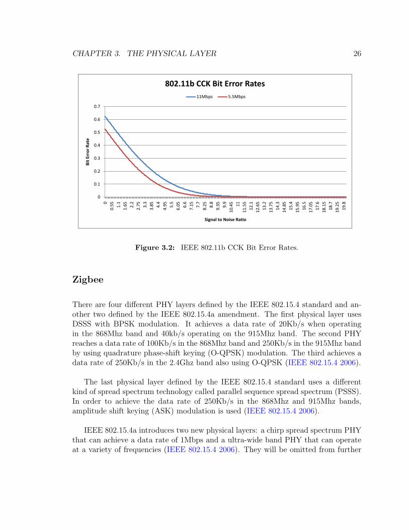
The IEEE 802.11b physical layer uses DSSS with a more advanced modulationtechnique called complementary code keying (CCK) that allows it to achieve 5.5Mbpsand 11Mbps data rates in addition to the original DSSS PHY rates of 1Mbps and2Mbps (Cooklev 2004). A metric called the bit error rate (BER) reflects the number ofbits incorrectly received per unit of time. It is affected by how resistant to propagationeffects the modulation technique is at different rates. The BER is also affected bythe strength of the received signal. Figure 3.2 depicts the BER at different radiosignal strengths for high-rate IEEE 802.11b. Since modulation does not occur at apacket-level simulation, this information is used in simulation predict the chance thatan error occurs in transmission for different signal strengths.
IEEE 802.11a does not use spread spectrum technology. Instead, it uses a modu-lation technique called orthogonal frequency division multiplexing (OFDM). OFDMworks by transmitting data in narrow, overlapping channels. This allows it to achievemuch higher data rates and use the wireless spectrum more efficiently. The IEEE802.11a PHY can achieve a maximum data rate of 54Mbps (Cooklev 2004).
IEEE 802.11g uses the same OFDM technology to transmit wireless data as IEEE802.11a and achieve the same maximum data rate. The other differences betweenIEEE 802.11a and IEEE 802.11g will be discussed in subsequent sections (Cooklev2004).
CHAPTER 3. THE PHYSICAL LAYER 25
A
D
Time Hopping Sequence: A C F E B F D A
F
B
EE
F
C
A Frequency 2.402 Ghz 2.480Ghz
Figure 3.1: Simplified IEEE 802.11 FHSS Hopping Sequence.
CHAPTER 3. THE PHYSICAL LAYER 26
0
0.1
0.2
0.3
0.4
0.5
0.6
0.70
0.55
1.1
1.65
2.2
2.75
3.3
3.85
4.4
4.95
5.5
6.05
6.6
7.15
7.7
8.25
8.8
9.35
9.9
10.45
11
11.55
12.1
12.65
13.2
13.75
14.3
14.85
15.4
15.95
16.5
17.05
17.6
18.15
18.7
19.25
19.8
Bit
Err
or
Rat
e
Signal to Noise Ratio
802.11b CCK Bit Error Rates
11Mbps 5.5Mbps
Figure 3.2: IEEE 802.11b CCK Bit Error Rates.
Zigbee
There are four different PHY layers defined by the IEEE 802.15.4 standard and an-other two defined by the IEEE 802.15.4a amendment. The first physical layer usesDSSS with BPSK modulation. It achieves a data rate of 20Kb/s when operatingin the 868Mhz band and 40kb/s operating on the 915Mhz band. The second PHYreaches a data rate of 100Kb/s in the 868Mhz band and 250Kb/s in the 915Mhz bandby using quadrature phase-shift keying (O-QPSK) modulation. The third achieves adata rate of 250Kb/s in the 2.4Ghz band also using O-QPSK (IEEE 802.15.4 2006).
The last physical layer defined by the IEEE 802.15.4 standard uses a differentkind of spread spectrum technology called parallel sequence spread spectrum (PSSS).In order to achieve the data rate of 250Kb/s in the 868Mhz and 915Mhz bands,amplitude shift keying (ASK) modulation is used (IEEE 802.15.4 2006).
IEEE 802.15.4a introduces two new physical layers: a chirp spread spectrum PHYthat can achieve a data rate of 1Mbps and a ultra-wide band PHY that can operateat a variety of frequencies (IEEE 802.15.4 2006). They will be omitted from further
CHAPTER 3. THE PHYSICAL LAYER 27
discussion.
The data rates for Zigbee are much lower than WiFi. The slowest WiFi physicallayer is still four times faster than the best original Zigbee PHY. Additionally, theIEEE 802.11a and IEEE 802.11g standards abandoned spread spectrum technologyto achieve higher data rates. The priorities of WiFi and Zigbee are clearly illustratedto be different.
3.2 Frequencies of Operation and Channels
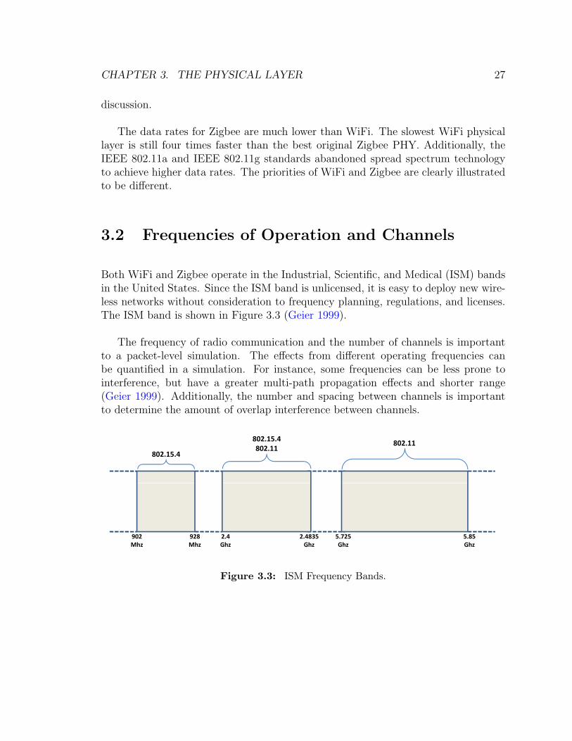
Both WiFi and Zigbee operate in the Industrial, Scientific, and Medical (ISM) bandsin the United States. Since the ISM band is unlicensed, it is easy to deploy new wire-less networks without consideration to frequency planning, regulations, and licenses.The ISM band is shown in Figure 3.3 (Geier 1999).
The frequency of radio communication and the number of channels is importantto a packet-level simulation. The effects from different operating frequencies canbe quantified in a simulation. For instance, some frequencies can be less prone tointerference, but have a greater multi-path propagation effects and shorter range(Geier 1999). Additionally, the number and spacing between channels is importantto determine the amount of overlap interference between channels.
802 15 4
802.15.4
802.15.4802.11
802.11
902Mhz
928Mhz
2.4Ghz
2.4835Ghz
5.725Ghz
5.85Ghz
Figure 3.3: ISM Frequency Bands.
CHAPTER 3. THE PHYSICAL LAYER 28
WiFi
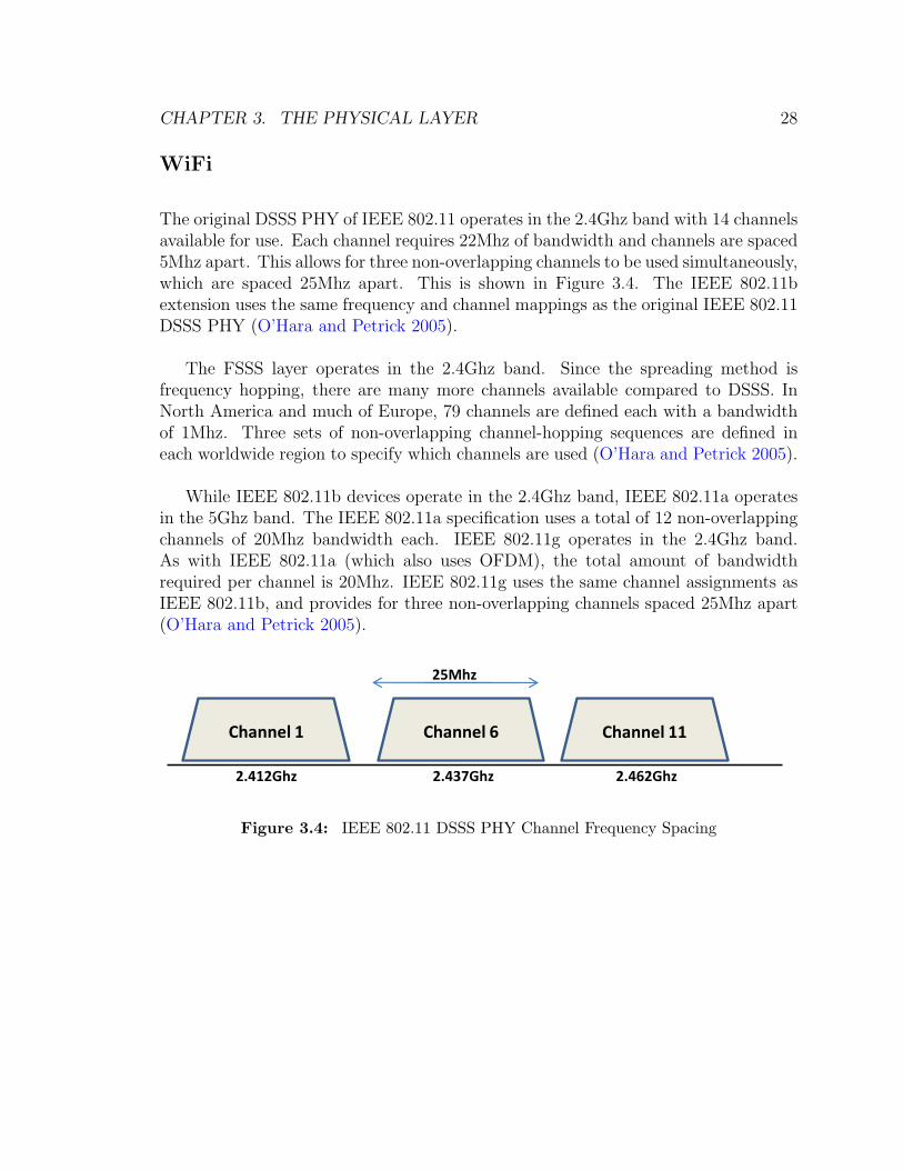
The original DSSS PHY of IEEE 802.11 operates in the 2.4Ghz band with 14 channelsavailable for use. Each channel requires 22Mhz of bandwidth and channels are spaced5Mhz apart. This allows for three non-overlapping channels to be used simultaneously,which are spaced 25Mhz apart. This is shown in Figure 3.4. The IEEE 802.11bextension uses the same frequency and channel mappings as the original IEEE 802.11DSSS PHY (O’Hara and Petrick 2005).
The FSSS layer operates in the 2.4Ghz band. Since the spreading method isfrequency hopping, there are many more channels available compared to DSSS. InNorth America and much of Europe, 79 channels are defined each with a bandwidthof 1Mhz. Three sets of non-overlapping channel-hopping sequences are defined ineach worldwide region to specify which channels are used (O’Hara and Petrick 2005).
While IEEE 802.11b devices operate in the 2.4Ghz band, IEEE 802.11a operatesin the 5Ghz band. The IEEE 802.11a specification uses a total of 12 non-overlappingchannels of 20Mhz bandwidth each. IEEE 802.11g operates in the 2.4Ghz band.As with IEEE 802.11a (which also uses OFDM), the total amount of bandwidthrequired per channel is 20Mhz. IEEE 802.11g uses the same channel assignments asIEEE 802.11b, and provides for three non-overlapping channels spaced 25Mhz apart(O’Hara and Petrick 2005).
25Mhz
Channel 1 Channel 6 Channel 11
2.412Ghz 2.437Ghz 2.462Ghz
Figure 3.4: IEEE 802.11 DSSS PHY Channel Frequency Spacing

CHAPTER 3. THE PHYSICAL LAYER 29
Zigbee
There are three frequency bands defined in the IEEE 802.15.4 standard: the 868Mhzband, 915Mhz band, and the 2.4Ghz band. The 868Mhz band is available for use inEurope, the 915Mhz is available in North America, and the 2.4Ghz band is availableworldwide (Gutierrez, Callaway Jr., and Barrett Jr. 2007).
The IEEE 802.15.4 standard uses pages, sets of channel numbers, to define channelassignments. A maximum number of 32 pages may be defined, but only three arecurrently specified in the standard. The remaining pages are reserved for future use.Each page contains a maximum of 27 non-overlapping channel assignments, numbered0 to 26 (IEEE 802.15.4 2006).
Page 0 specifies channel assignments for the 2.4Ghz and 868/915Mhz BPSK PHYs.It allocates one channel for the 868Mhz band, 10 for the 915Mhz band, and 16 channelsfor the 2.4Ghz band. Channels are spread evenly through the available spectrum andspaced 2Mhz apart for the 868/915Mhz bands and 5Mhz apart for the 2.4Ghz band(IEEE 802.15.4 2006). The channel spacing for the 2.4Ghz PHY is shown in Figure3.5.
Page 1 specifies channel assignments for the 868/915Mhz PSSS PHY. It allocatesone channel in the 868Mhz band and 10 in the 915Mhz band. Channel assignmentsfor Page 2 are identical to Page 1, except it describes the 868/915Mhz O-QPSK PHY(IEEE 802.15.4 2006).
2.405Ghz
11 12 13 14 15 16 17 18 19 20 21 22 23 24 25 26
2.480Ghz2.445Ghz
2Mhz
Figure 3.5: IEEE 802.15.4 2.4Ghz PHY Channel Frequency Spacing
CHAPTER 3. THE PHYSICAL LAYER 30
3.3 Range and Power
The range of signals and the power needed to operate the device are important factorsin distinguishing between different wireless standards. Given the different purposesand applications of WiFi and Zigbee, it is expected that the power requirements andoperating range will be different.
The range of a radio signal depends on the amount of power used for transmission.The relationship between the two is positive: the more power used, the greater therange. The amount of power used for transmission is important because every wirelessdevice has a specific minimum receive power level. Data that is received below a setsignal strength cannot be interpreted. It is possible to calculate the maximum distancea signal can be transmitted using power loss equations. In free space, the power loss(in dBm) is given by
Pr = P0 − 10n log d
where P0 is the received power at a 1m distance, n is a factor dependent on theenvironment (typically 1.6 to 3.3 indoors), and d is the is the distance between devices(Cooklev 2004). To convert from watts to dB, multiply the log base 10 of Watts by10.
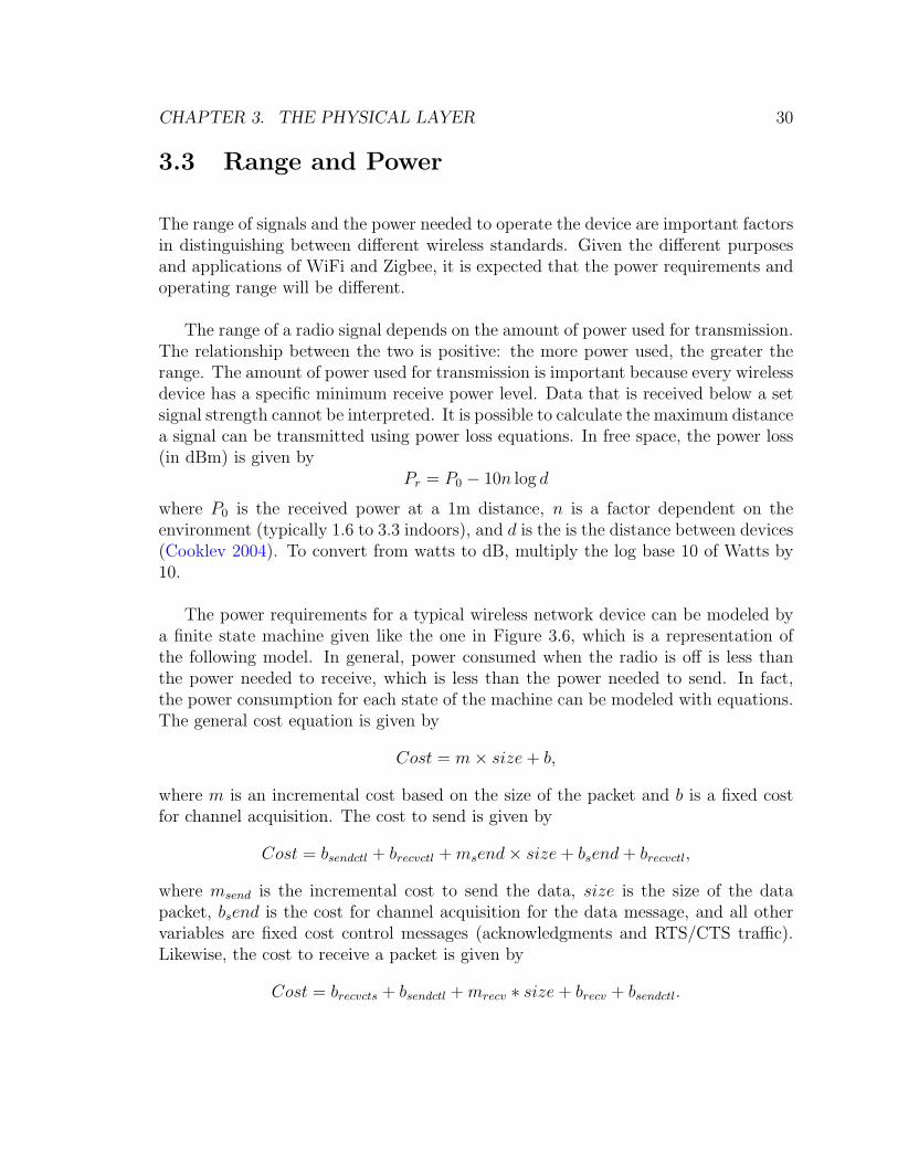
The power requirements for a typical wireless network device can be modeled bya finite state machine given like the one in Figure 3.6, which is a representation ofthe following model. In general, power consumed when the radio is off is less thanthe power needed to receive, which is less than the power needed to send. In fact,the power consumption for each state of the machine can be modeled with equations.The general cost equation is given by
Cost = m× size + b,
where m is an incremental cost based on the size of the packet and b is a fixed costfor channel acquisition. The cost to send is given by
Cost = bsendctl + brecvctl + msend× size + bsend + brecvctl,
where msend is the incremental cost to send the data, size is the size of the datapacket, bsend is the cost for channel acquisition for the data message, and all othervariables are fixed cost control messages (acknowledgments and RTS/CTS traffic).Likewise, the cost to receive a packet is given by
Cost = brecvcts + bsendctl + mrecv ∗ size + brecv + bsendctl.

CHAPTER 3. THE PHYSICAL LAYER 31
Sleep
Power Down Power Up
Idle
Transmit State Receive State Machine Machine
Figure 3.6: Physical Layer State Machine.
CHAPTER 3. THE PHYSICAL LAYER 32
By conducting a power analysis of network cards, it is possible to determine the valuesfor each of the variables and use them in a simulation to model energy consumption(Feeney 2001).
WiFi
In Feeney 2001, such a power analysis is conducted for WiFi. Through measuringpower consumption by a IEEE 802.11 network card, the constants for the abovevariables are determined. This allows a simulation model to be constructed using thecombination of the equations and the experimentally determined constant values. Inaddition to generalizing the power model, it is useful to dig deeper to discover thespecifications of the IEEE 802.11 standard that relate to power consumption.
The maximum power output allowable by US regulations is 1 watt in the 2.4Ghzoperating frequency. However, many vendors have set the default output power to100mW in order to conserve power and abide by European regulations. In openareas, IEEE 802.11b can achieve an operating range of about 1000 feet, but this issignificantly lowered to about 150-300 feet indoors. (Cooklev 2004).
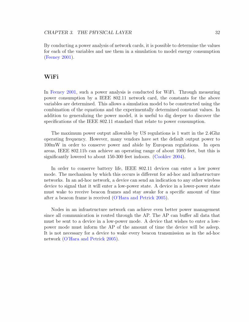
In order to conserve battery life, IEEE 802.11 devices can enter a low powermode. The mechanism by which this occurs is different for ad-hoc and infrastructurenetworks. In an ad-hoc network, a device can send an indication to any other wirelessdevice to signal that it will enter a low-power state. A device in a lower-power statemust wake to receive beacon frames and stay awake for a specific amount of timeafter a beacon frame is received (O’Hara and Petrick 2005).
Nodes in an infrastructure network can achieve even better power managementsince all communication is routed through the AP. The AP can buffer all data thatmust be sent to a device in a low-power mode. A device that wishes to enter a low-power mode must inform the AP of the amount of time the device will be asleep.It is not necessary for a device to wake every beacon transmission as in the ad-hocnetwork (O’Hara and Petrick 2005).

CHAPTER 3. THE PHYSICAL LAYER 33
Zigbee
Similar to (Feeney 2001), a IEEE 802.15.4 power model is presented in (Mura,Paolieri, and Fabbri 2007). However, the data presented is not compatible withthe cost equations above. Instead, the equivalents of msend and mrecv are given interms of power, not energy per byte. In order to use the same cost equations, allinstances of mrecv/send × size must be replaced with precv/send × time where psend/recv
is the transmit or receive power and time is the amount of time needed to send. Aswith WiFi, it is necessary to explain what drives power consumption according to theIEEE 802.15.4 standard.
The minimum output required by IEEE 802.15.4 for a wireless device is -3dBm.Since the standard was especially written with low power consumption in mind, mostdevices will transmit between 0dBm and 10dBm although a maximum of 1W (30dBm)is allowed by the FCC. A lower power output is encouraged in order to reduce in-terference between devices and save energy (IEEE 802.15.4 2006). However, loweringthe transmit power will also decrease the visibility of nodes and contribute to thehidden node problem, discussed in Chapter 2.
Like IEEE 802.11, IEEE 802.15.4 specifies a mechanism by which devices canoperate under a low-power mode. When operating with beacons, a coordinator cansplit the time between beacons into an active and an inactive portion. No data isexchanged during the inactive period. This allows coordinators and other devicesto enter a low-power mode and awake at the beginning of the next active period(Gutierrez, Callaway Jr., and Barrett Jr. 2007).
3.4 PHY Packet Structure
WiFi
There are two sublayers within the IEEE 802.11 physical layers. The physical layerconvergence procedure (PLCP) sublayer is responsible for communicating with theMAC layer. The physical medium dependent (PMD) sublayer is responsible for trans-mitting the binary data received by the PLCP sublayer (O’Hara and Petrick 2005).
In IEEE 802.11, physical layer frames are called PLCP protocol data units (PP-
CHAPTER 3. THE PHYSICAL LAYER 34
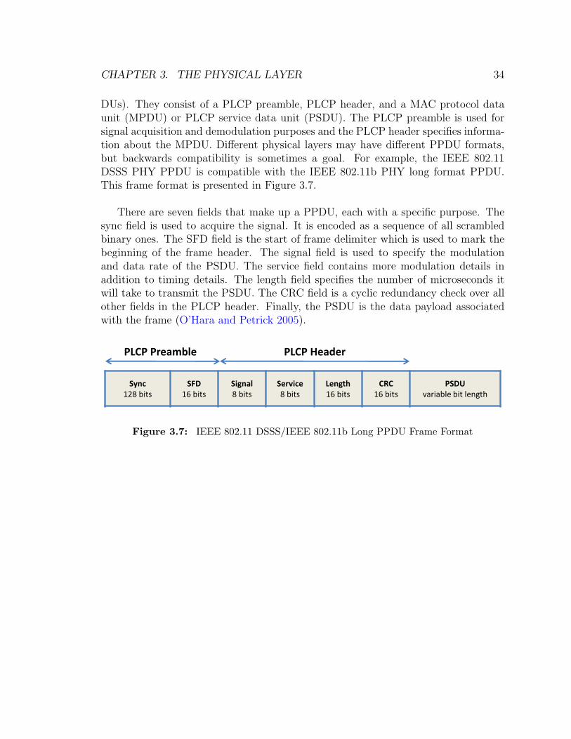
DUs). They consist of a PLCP preamble, PLCP header, and a MAC protocol dataunit (MPDU) or PLCP service data unit (PSDU). The PLCP preamble is used forsignal acquisition and demodulation purposes and the PLCP header specifies informa-tion about the MPDU. Different physical layers may have different PPDU formats,but backwards compatibility is sometimes a goal. For example, the IEEE 802.11DSSS PHY PPDU is compatible with the IEEE 802.11b PHY long format PPDU.This frame format is presented in Figure 3.7.
There are seven fields that make up a PPDU, each with a specific purpose. Thesync field is used to acquire the signal. It is encoded as a sequence of all scrambledbinary ones. The SFD field is the start of frame delimiter which is used to mark thebeginning of the frame header. The signal field is used to specify the modulationand data rate of the PSDU. The service field contains more modulation details inaddition to timing details. The length field specifies the number of microseconds itwill take to transmit the PSDU. The CRC field is a cyclic redundancy check over allother fields in the PLCP header. Finally, the PSDU is the data payload associatedwith the frame (O’Hara and Petrick 2005).
PLCP Preamble
Sync128 bits
SFD16 bits
Signal8 bits
Service8 bits
Length16 bits
CRC16 bits
PSDUvariable bit length
PLCP Header
Figure 3.7: IEEE 802.11 DSSS/IEEE 802.11b Long PPDU Frame Format

CHAPTER 3. THE PHYSICAL LAYER 35
Zigbee
Three main fields divide the IEEE 802.15.4 PPDU: the synchronization header, thePHY header, and the PSDU. The PPDU frame format for the 2.4Ghz O-QPSK PHYis presented in Figure 3.8. Frame formats for the other PHYs are identical in layoutbut differ only in the bit lengths of the synchronization header fields (IEEE 802.15.42006).
There are five fields that make up a IEEE 802.15.4 PHY frame. The preamblefield is comparable to the sync field of IEEE 802.11. It is used to synchronize thereceived. The SFD field is the start of frame delimiter to indicate the division betweenthe preamble and frame length fields. The frame length field indicates the numberof octets in the PSDU. Finally, the PSDU is the data payload for the frame (IEEE802.15.4 2006).
The IEEE 802.15.4 standard does not include many fields seen in the IEEE 802.11PPDU. This speaks to the simplicity of implementation and operation Zigbee strivesto achieve.
Sync Header
Preamble32 bits
SFD8 bits
Frame Length7 bits
Reserved1 bit
PSDUvariable bit length
PHY Header
Figure 3.8: IEEE 802.15.4 2.4Ghz O-QPSK PPDU Frame Format

CHAPTER 3. THE PHYSICAL LAYER 36
3.5 Chapter Summary
In this chapter, the different physical layers of WiFi and Zigbee were examined. Eachstandard defines multiple PHYs that can use different techniques to modulate, andsend the signal. The differences in modulation determine how the signal is encodedfor transmission, the resulting data rates, and the probability of producing errors.In general, IEEE 802.11 uses more complex ways to modulate the signal to achievehigher data rates than Zigbee. The operating frequencies of each wireless protocolalso differ. Wifi and Zigbee both operate in the 2.4Ghz band, but IEEE 802.11 alsoallows operation in the 5Ghz band while Zigbee offers operation in the 868Mhz and915Mhz bands. The operating range and power requirements of both protocols differbased on the uses for which they are intended. Finally, the physical layer packetstructure of both protocols have many commonalities such as preambles and start offrame delimiters.
In the next chapter, the details of implementing the IEEE 802.15.4 standard inan existing network simulator are discussed.

37
Chapter 4
Simulating Zigbee
4.1 Introduction to SWAN
The Simulator for Wireless Ad-hoc Networks (SWAN) is an ongoing research projectat Bucknell led by Professor Felipe Perrone. Its purpose is to simulate wireless ad-hocnetworks in order to further understand their properties. SWAN is built in C++ anduses the Dartmouth Scalable Simulation Framework (DaSSF) for event scheduling,statistics collection, and other low-level functions (Perrone 2009).
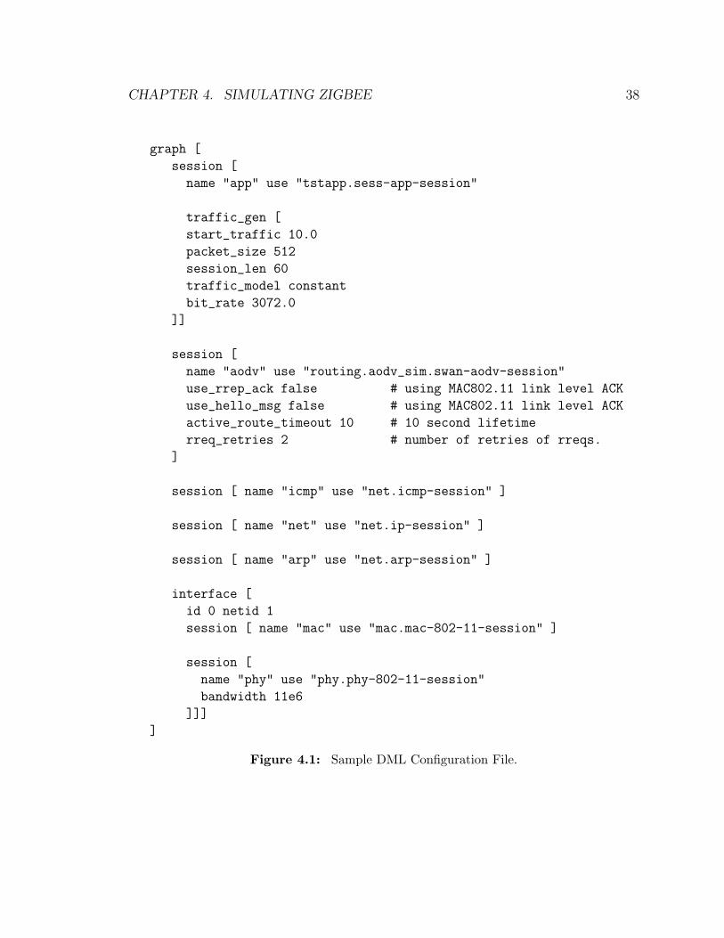
SWAN simulations are easily configurable by end users. In order to run experi-ments, parameters must first be supplied to SWAN. This is accomplished through theuse of a special text file written using the Domain Modeling Language (DML). A DMLfile consists of a sequence of key-value pairs that specify the parameter to configureand the value it will hold. These parameters include the number of wireless devicesin the simulation, their positions in 3D space, and their mobility patterns. A DMLfile for the simulation of a IEEE 802.11 wireless network is presented in Figure 4.1(Perrone 2009). Simulations are easily configurable by end users. In order to run ex-periments, parameters must first be supplied to SWAN. This is accomplished throughthe use of a special text file written using Domain Modeling Language (DML). A DMLfile consists of a sequence of key-value pairs that specify the parameter to configureand the value it will hold. These parameters include the number of wireless devices inthe simulation, their relative distances, and their mobility patterns (Perrone 2009).
CHAPTER 4. SIMULATING ZIGBEE 38
graph [
session [
name "app" use "tstapp.sess-app-session"
traffic_gen [
start_traffic 10.0
packet_size 512
session_len 60
traffic_model constant
bit_rate 3072.0
]]
session [
name "aodv" use "routing.aodv_sim.swan-aodv-session"
use_rrep_ack false # using MAC802.11 link level ACK
use_hello_msg false # using MAC802.11 link level ACK
active_route_timeout 10 # 10 second lifetime
rreq_retries 2 # number of retries of rreqs.
]
session [ name "icmp" use "net.icmp-session" ]
session [ name "net" use "net.ip-session" ]
session [ name "arp" use "net.arp-session" ]
interface [
id 0 netid 1
session [ name "mac" use "mac.mac-802-11-session" ]
session [
name "phy" use "phy.phy-802-11-session"
bandwidth 11e6
]]]
]
Figure 4.1: Sample DML Configuration File.
CHAPTER 4. SIMULATING ZIGBEE 39
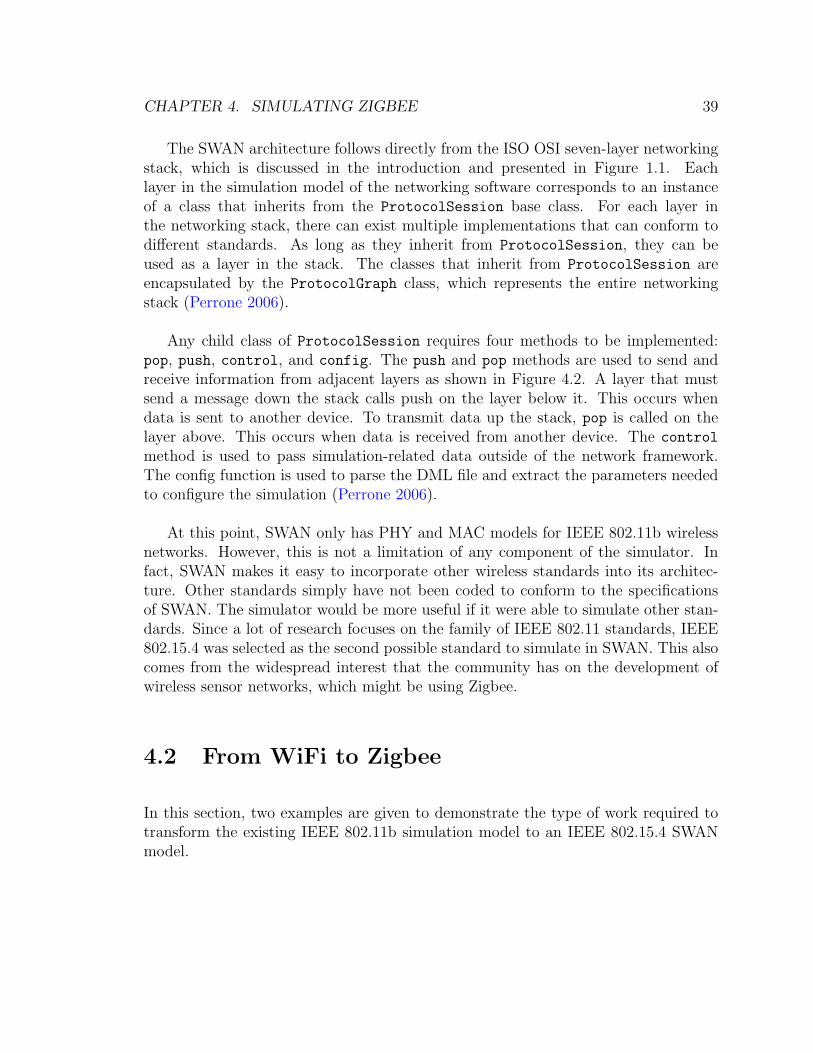
The SWAN architecture follows directly from the ISO OSI seven-layer networkingstack, which is discussed in the introduction and presented in Figure 1.1. Eachlayer in the simulation model of the networking software corresponds to an instanceof a class that inherits from the ProtocolSession base class. For each layer inthe networking stack, there can exist multiple implementations that can conform todifferent standards. As long as they inherit from ProtocolSession, they can beused as a layer in the stack. The classes that inherit from ProtocolSession areencapsulated by the ProtocolGraph class, which represents the entire networkingstack (Perrone 2006).
Any child class of ProtocolSession requires four methods to be implemented:pop, push, control, and config. The push and pop methods are used to send andreceive information from adjacent layers as shown in Figure 4.2. A layer that mustsend a message down the stack calls push on the layer below it. This occurs whendata is sent to another device. To transmit data up the stack, pop is called on thelayer above. This occurs when data is received from another device. The control
method is used to pass simulation-related data outside of the network framework.The config function is used to parse the DML file and extract the parameters neededto configure the simulation (Perrone 2006).
At this point, SWAN only has PHY and MAC models for IEEE 802.11b wirelessnetworks. However, this is not a limitation of any component of the simulator. Infact, SWAN makes it easy to incorporate other wireless standards into its architec-ture. Other standards simply have not been coded to conform to the specificationsof SWAN. The simulator would be more useful if it were able to simulate other stan-dards. Since a lot of research focuses on the family of IEEE 802.11 standards, IEEE802.15.4 was selected as the second possible standard to simulate in SWAN. This alsocomes from the widespread interest that the community has on the development ofwireless sensor networks, which might be using Zigbee.
4.2 From WiFi to Zigbee
In this section, two examples are given to demonstrate the type of work required totransform the existing IEEE 802.11b simulation model to an IEEE 802.15.4 SWANmodel.

CHAPTER 4. SIMULATING ZIGBEE 40
ProtocolSession N‐1
ProtocolSession N+1
ProtocolSession N
control
(pop)
(push)
(push)
(pop)
Figure 4.2: The SWAN ProtocolSession API.
4.2.1 Power Model
As discussed in Section 3.3, Feeney (2001) provides a power model for IEEE 802.11wireless networks. These values are used in SWAN to determine the amount of energythat must be deducted from the battery following a radio operation. The code ispresented in Figure 4.3. The code is fairly straightforward; since Feeney (2001) givesthe cost values (msend/recv) in energy per byte, the duration of the radio operationmust be converted to number bytes sent or received during that time interval. Thisis easily accomplished multiplying the bandwidth by the time duration. Then, basedon the operation, the power is deducted according to the specific radio operation andits associated m cost.
Mura, Paolieri, and Fabbri (2007) provides a power consumption model for IEEE802.15.4 which documents the power requirements for sending and receiving in termsof power units mW. Therefore, in order to adapt the SWAN code to represent theIEEE 802.15.4 power model, the duration multiplied by the power required for theradio operation (send/receive) is the amount of energy to subtract from the battery.Unfortunately, the bandwidth at which the power constants were obtained was notgiven, but it can be assumed to be 250kbps.

CHAPTER 4. SIMULATING ZIGBEE 41
void Host::battery_decrement(int mode, double duration, int iface) {
if (battery_alive) {
Phy80211Session* myPHY = (Phy80211Session*)getLowestSession(iface);
assert(myPHY);
double bwidth = myPHY->getBandwidth();
double bytes = duration * bwidth / 8;
switch(mode) {
case POWER_PTP_SEND:
battery_power -= (PowerConstant::mSend(bwidth) * bytes) +
PowerConstant::bSend(bwidth);
break;
case POWER_BROAD_SEND:
battery_power -= (PowerConstant::mBroadSend(bwidth) * bytes) +
PowerConstant::bBroadSend(bwidth);
break;
.
.
.
case POWER_IDLE: { // "Idle" consumption (no communication)
battery_power -= (PowerConstant::idle(bwidth) *
(VirtualTime(getNow()).second() - last_status_change.second()));
last_status_change = getNow();
} break;
default:
error_quit("Host::battery_decrement invalid mode");
}
if (battery_power <= 0){
reboot(INFINITY);
battery_alive = false;
}
}
Figure 4.3: SWAN Code Showing Battery Consumption.

CHAPTER 4. SIMULATING ZIGBEE 42
4.2.2 Bit Error Rate Model
Discussed in Section 3.1, the bit error rate (BER) measures the number of bytesreceived incorrectly per unit of time. If bits have been corrupted, the received packetof data must be discarded. The BER depends on the type of modulation used andthe signal to noise ratio. For higher signal to noise ratios, the BER is reduced.
The SWAN code that uses the BER to determine packet loss is presented inFigure 4.4. No bit errors actually happen during a simulation since it is running on acomputer. However, it is possible to calculate the probability that they would occuron a real network. This probability is based on the BER and the size of the packet.The BER is determined through a lookup into the graph shown in Figure 3.2 forIEEE 802.11b CCK.
bool FixedRangeRadioNetwork::acceptFrame(Modulation m, double
signalPower_dBm, double noisePower_dBm, int size)
{
double BER = compute_BER(m, signalPower_dBm, noisePower_dBm);
double p, DBPSK_BER;
// simplified computation for frame error rate
p = (double) 1.0 - pow((1.0 - BER), (double) size);
if (rng->bernoulli(p)) {
return false;
}
else {
return true;
}
}
Figure 4.4: Simplified SWAN Code Showing Packet Acceptance.
Different modulation techniques are used by Zigbee. For instance, the 2.4GhzPHY uses O-QPSK modulation instead of CCK. Therefore, the data in Figure 3.2will need to be replaced by a different function specific to O-QPSK. The BER equationfor Zigbee PHYs can be found in IEEE 802.15.4 2006.
CHAPTER 4. SIMULATING ZIGBEE 43
4.3 The ns-2 Implementation
The ns-2 network simulator is a versatile discrete-event network simulator. Its mainpurpose was to facilitate the research of many different network protocols and wasdesigned to be capable of scaling the simulation to handle a large number of networknodes. In addition to the large number of protocols it could simulate, it also had widedeveloper support (Breslau et al. 2000).
The ns-2 simulator uses a unique split-language programming model. To set upand configure a simulation, ns-2 uses an interpreted language called OTcl to describethe experiments. Whereas the C++ core of ns-2 is mainly used for packet processingand coding of the major network functions, OTcl is used to configure the simulationand directly manipulate the C++ classes. It is very different from a SWAN DMLfile which defines the structure of the model and also assigns values to its parameters(Fall and Varadhan 2009).
The ns-2 IEEE 802.15.4 implementation is written in C++ and is capable of run-ning on ns-2 2.26 and above. It implements most of the features of Zigbee includingpure and slotted CSMA-CA, star and peer-to-peer network configurations, and bothbeacon and beaconless operation (Zheng 2004). The Guaranteed Time Slot featureof Zigbee to produce contention-free periods is not supported (Zheng and Lee 2004).
There are several reasons why using ns-2 is undesirable to simulate IEEE 802.15.4networks. First, the architectural purity of the simulator has suffered under the largeamount of development for the platform. The simulator core was not general enoughin order to simulate all the different models that were developed. For instance, ns-2was not able to simulate wireless networks until a second node model was introduced(Perrone et al. 2009).
Second, it is difficult to configure a scenario to simulate. Due to the complexityof the split-level programming model, it is not always clear where configuration pa-rameters are to be specified. Sometimes they must be given in the OTcl, other timesthey must be explicitly set in C++ header files. Poor and out of date documentationexacerbates this problem (Perrone et al. 2009).
Finally, ns-2 lacks tools to analyze simulation results. The simulator producespacket traces in the form of text files that can be difficult to interpret. These tracefiles can be very large even for relatively small simulations. The lack of proper analysistools often requires individual researchers to create specialized programs to interpret
CHAPTER 4. SIMULATING ZIGBEE 44
the packet traces (Cicconetti et al. 2006).
For these reasons, it would be best to develop an IEEE 802.15.4 implementationin SWAN.
4.4 Challenges in a SWAN Implementation
The implementation of the IEEE 802.15.4 standard in SWAN was much more difficultthan originally anticipated. Working from an existing implementation of Zigbee onthe ns-2 network simulator, the most desirable final product is a port of the code forthat simulator into SWAN.
This thesis explains the basic architecture of the SWAN code and discusses theimplementation details of the ns-2 code. The implementation of the physical layerfor IEEE 802.15.4 in SWAN is drafted here and its further development will need toaddress the following three main challenges.
4.4.1 Conflicting Data Types
SWAN and ns-2 have different type specifications for similar data structures. Forexample, in the implementation of IEEE 802.15.4 in ns-2, the physical layer sendsand receives Packet objects that hold header bits and data for the application level.In the SWAN implementation, similar data is stored in RadioFrame objects. TheRadioFrame object stores information about the source and destination MAC ad-dresses, transmission duration, and other information in explicitly named variables,unlike a ns-2 Packet object. The RadioFrame and Packet class definitions are pre-sented in an abbreviated form in Figure 4.5. In order to port the ns-2 implementationto SWAN, all references to ns-2 objects in its IEEE 802.15.4 will need to be changedto their SWAN counterparts. This requires considerable effort in the analysis of whena data type must be translated.

CHAPTER 4. SIMULATING ZIGBEE 45
class Packet : public Event {
private:
friend class PacketQueue;
u_char* bits_;
u_char* data_;
u_int datalen_;
protected:
static Packet* free_;
public:
Packet* next_;
static int hdrlen_;
Packet() : bits_(0),
datalen_(0), next_(0) {}
};
class RadioFrame : public SSF_Event {
public:
int netid;
MACADDR to_addr;
MACADDR from_addr;
ltime_t duration;
void* frame;
int framelen;
float xpos;
float ypos;
float zpos;
double tx_power_dbm;
double tx_antenna_gain_db;
RadioFrame(int nid, MACADDR from, MACADDR to,
ltime_t duration, void* frame, int framelen,
boolean need_copying = false);
};
Figure 4.5: Comparison of SWAN and ns-2 Data Types
CHAPTER 4. SIMULATING ZIGBEE 46
4.4.2 Poor ns-2 IEEE 802.15.4 Documentation
In addition to mismatched data types, the poor state of the IEEE 802.15.4 imple-mentation documentation makes it much more difficult to port to SWAN. It is easyto identify the purpose of most of the methods and data types provided in the code.However, the method bodies are difficult to understand since they lack proper codecomments. On a line-by-line basis, it is nearly impossible to discern what needs tobe ported to SWAN.
The situation is more complex when considering the architecture of the core ns-2code. As stated in Section 4.3, the poor adherence split-level programming model hascomplicated the implementation and simulation of different networking models. Withconfiguration parameters spread in two locations, it becomes much more difficult toextract the code that is necessary for the simulation to work properly. Addition-ally, the mix between the interpreted OTcl simulation code and the core C++ codemakes it difficult to know if one is looking at network configuration parameters for asimulation or the code that drives the simulation.
The relationship between the IEEE 802.15.4 model and the core ns-2 code is muchlike a ball of tangled wires. In order to get the one needed wire out of the mess, ittakes a careful process of examining how that wire interacts with all the other wires.The wire then must be picked apart and finally extracted.
4.4.3 Verification and Validation
The IEEE 802.15.4 SWAN implementation must be verified and validated to ensureits correctness. In order to verify the simulation, the code must be properly debugged.This can be accomplished through standard programming procedures such as devel-oping and testing in smaller units, code review, and testing input parameters (Law2007).
Verification in the form of debugging is not the only requirement. Although thesimulation may act in the way the programmer intended, it does not ensure it modelsthe real-world implementation correctly. This goal is accomplished through the pro-cess of validation. Validation involves comparing the results to another model, thereal-world system, or comparing with an expert opinion (Law 2007).

CHAPTER 4. SIMULATING ZIGBEE 47
First, the ns-2 code should be validated by conducting experiments with actualIEEE 802.15.4 hardware. Two or more wireless devices should form a network andexchange data. Then, the same setup can be configured through the ns-2 OTcl code.If the results of the real-world experiment and the simulation match closely, the modelis valid. If there are significant differences between the experiment and the simulation,the simulation must be modified (Law 2007).
Once the ns-2 code is validated, the model can be ported to SWAN. In orderto validate the IEEE 802.15.4 code, it should first be compared to a known systems(Law 2007). Naturally, the first system it should be compared with is the ns-2implementation. By setting the same parameters for the two network simulators, theresults of experiments should match. If there are large differences between the twosimulation results, it indicates that the port from ns-2 to SWAN introduced problemswith the simulation. Experiments with IEEE 802.15.4 can then be conducted to matchthe simulation and hardware results.
4.5 Chapter Summary
SWAN is a powerful ad-hoc wireless network simulator, but it can only simulate IEEE802.11b networks. In order to make SWAN more useful, IEEE 802.15.4 was chosenas another wireless protocol it should simulate given the research interest in wirelesssensor networks. Since the ns-2 network simulator has an existing implementationof IEEE 802.15.4, we decided that it would be best to port that implementation toSWAN. However, this creates a new set of difficulties given the differences in datatypes between the two simulators, the poor documentation of ns-2, and challenge ofverification and validation.
In the next chapter, a road map to implement IEEE 802.15.4 in SWAN is presentedand final thoughts are given.

48
Chapter 5
Conclusion and Future Work
This thesis explained and compared the IEEE 802.11 and IEEE 802.15.4 wirelessnetworking standards. It was shown that they resembled each other closely from asimulation perspective by examining their network topologies, MAC layers, and PHYlayers. However, there are many small but important differences between the twostandards that must be accounted for in the construction of simulation models.
First, WiFi and Zigbee are both technologies that can be used to form unstruc-tured, ad-hoc networks. However, the goals of the networks are different. WiFinetworks are optimized for high-bandwidth communication whereas Zigbee networksuse low-bandwidth and consume much less power. This makes WiFi suitable forInternet access and file sharing and Zigbee suitable for sensor networks.
Second, their MAC layers are very similar since they both provide contentionand contention-free access. Contention access for both standards use CSMA/CAto manage the shared medium and avoid collisions. Contention-free access is madepossible by the Point Coordination Function in a WiFi network to grant a device theprivilege to transmit. Zigbee uses Guaranteed Time Slots and the PAN Coordinatorto schedule times when a single device can transmit. While the MAC layers are similarin many ways, WiFi and Zigbee handle the hidden node problem differently: Zigbeeignores it completely and WiFi uses special control messages to check if the destinationnode is currently receiving data from another device. All of these properties are veryimportant when building a simulation model.
CHAPTER 5. CONCLUSION AND FUTURE WORK 49
Third, the PHY layers of WiFi and Zigbee are similar in general principles, butdiffer in specifications and parameters. Both use Direct Sequence Spread Spectrummodulation to spread the wireless signal across many frequencies. However, the datarates for even the original IEEE 802.11 DSSS PHY (2Mbps) is much higher thanfor IEEE 802.15.4 (250Kbps). Additionally, WiFi and Zigbee both operate in theunlicensed ISM band of frequencies but use different transmission powers due to thedifferent goals in range of coverage. These physical layer specifications are less impor-tant to a simulation model than the MAC layer specification because the propagationof electromagnetic signals are not being simulated. For instance, the details abouthow a specific type of modulation works are not important because that is not whatis being simulated. Instead, the general performance of a modulation technique (forinstance, how it affects the bit error rate) is important to a packet-level simulation.
To follow through on the purpose of this thesis, it would be beneficial to obtainworking Zigbee devices in order to run experiments and learn from it directly. Adevice such as the Freescale MC1202 would be suitable for this purpose. Instead ofthinking of Zigbee as a foreign and unfamiliar protocol, actual hardware would makeit seem within reach. It would also be essential in the validation of the simulationmodel once it is completed.
In order to create a working simulation model of Zigbee within SWAN, much workis still needed. The best course of action would be to use the existing ns-2 802.15.4simulation model and port it to SWAN. Unfortunately, this presents a new set ofchallenges to change ns-2 -based code to a SWAN equivalent.
This thesis can be used as a guide to implement the IEEE 802.15.4 simulationmodel in SWAN. The comparison of WiFi to Zigbee that this thesis provides willmake it easier to implement a Zigbee model with the known reference point of WiFi.

50
Bibliography
Breslau, L., D. Estrin, K. Fall, S. Floyd, J. Heidemann, A. Helmy, P. Huang,S. McCanne, K. Varadhan, Y. Xu, and H. Yu (2000). Advances in networksimulation. Computer 33 (5), 59–67.
Cicconetti, C., E. Mingozzi, and G. Stea (2006). An integrated framework for en-abling effective data collection and statistical analysis with ns-2. In Proceedingsof the 2006 Workshop on ns-2: The IP Network Simulator (SWNS2 ’06), Pisa,Italy.
Cooklev, T. (2004). Wireless Communication Standards. IEEE Press.
Fall, K. and K. Varadhan (2009). The ns Manual.
Feeney, L. M. (2001). An energy consumption model for performance analysis ofrouting protocols for mobile ad hoc networks. Mob. Netw. Appl. 6 (3), 239–249.
Geier, J. (1999). Wireless LANs: Implementing Interoperable Networks. MacmillanTechnical Publishing.
Gutierrez, J. A., E. H. Callaway Jr., and R. L. Barrett Jr. (2007). Low-Rate WirelessPersonal Area Networks. IEEE Press.
Harthikote-Matha, M., T. Banka, and A. P. Jayasumana (2007). Performancedegradation of IEEE 802.15.4 slotted CSMA/CA due to hidden nodes. In Pro-ceedings of the 32nd IEEE Conference on Local Computer Networks (LCN ’07),Washington, DC, USA, pp. 264–266. IEEE Computer Society.
Hwang, L.-J., S.-T. Sheu, Y.-Y. Shih, and Y.-C. Cheng (2005). Grouping strat-egy for solving hidden node problem in IEEE 802.15.4 LR-WPAN. In WICON’05: Proceedings of the First International Conference on Wireless Internet,Washington, DC, USA, pp. 26–32. IEEE Computer Society.
IEEE 802.11 (2007). IEEE 802.11 Standard.
IEEE 802.15.4 (2006). IEEE 802.15.4 Standard.
Law, A. M. (2007). Simulation and Modeling Analysis (4rd ed.). McGraw-Hill.

BIBLIOGRAPHY 51
Liu, J., F. L. Perrone, D. M. Nicol, C. Elliott, and D. Pearson (2001). Simulationmodeling of large-scale ad-hoc sensor networks. In Proceedings of the EuropeanSimulation Interoperability Workshop 2001 (EURO-SIW 2001), London, Eng-land.
Mura, M., M. Paolieri, and F. Fabbri (2007). Power modeling and power analysisfor ieee 802.15.4: a concurrent state machine approach. In Consumer Commu-nications and Networking Conference (CCNC 2007), Las Vegas, NV, U.S.A.,pp. 660–664.
O’Hara, B. and A. Petrick (2005). IEEE 802.11 Handbook. IEEE Press.
Perrone, F. (2006). SWAN: A simulator for wireless ad hoc networks. Invited Talkat Universita di Bologna, Italy; http://www.eg.bucknell.edu/~perrone/
research/UniBo-2.ppt [Accessed May 1, 2009].
Perrone, F. (2009). SWAN User’s Manual.
Perrone, F. L. and S. C. Nelson (2006). A study of on-off attack models for wirelessad hoc networks. In First IEEE International Workshop on Operator-Assisted(Wireless Mesh) Community Networks (OpComm 2006), Berlin, Germany.
Perrone, L. F., C. Cicconetti, G. Stea, and B. C. Ward (2009). On the automation
of computer network simulators. In Proceedings of the 2nd International Con-ference on Simulation Tools and Techniques (SIMUTools 2009), Rome, Italy.
Rappaport, T. (1996). Wireless Communications: Principles and Practice. Engle-wood Cliffs, NJ: Prentice Hall.
Tanenbaum, A. S. (2003). Computer Networks (4rd ed.). Prentice Hall.
Zheng, J. (2004). 802.15.4 and Zigbee routing simulation at Samsung/CUNY.http://www-ee.ccny.cuny.edu/zheng/pub/file/WPAN_ZBR_pub.pdf [Ac-cessed May 1st, 2009].
Zheng, J. and M. J. Lee (2004). WPAN ns-2 Simulation Model FAQs.http://www-ee.ccny.cuny.edu/zheng/pub/Pages/wpan-ns2-faq.htm [Ac-cessed May 1st, 2009].