Embed Size (px)
Citation preview

A Combined Experimental and Modeling Approach for the
Design of High Coulombic Efficiency Si Electrodes
Xingcheng Xiao
General Motors Global R&D Center
Yue Qi
Michigan State University
Brian Sheldon, Huajian Gao
Brown University
Yang-Tse Cheng
University of Kentucky
June 9, 2016
This presentation does not contain any proprietary, confidential, or otherwise restricted information
ES221

• Project start date: 5/17/2013• Project end date:4/1/2017• Percent completed: 80%
High energy materials with • Short calendar and cycle life • Low coulombic efficiency • High cost
• Total project funding: $1,318,947• DOE share: $1,318,947• Contractor share: $0• Funding received in FY15:
$300,000• Funding for FY16: $300,000
Timeline
Budget
Barriers addressed
Interactions/ collaborations• LBNL: Gao Liu: polymer binder• PNNL: Chongmin Wang: in-situ TEM• NREL: Chunmei Ban: Advanced surface
coating• U. Waterloo: Zhongwei Chen, Si
nanostructure• Sandia: Kevin Leung: e transport in ALDProject lead: General Motors
Partners
Overview
2

Objective and RelevanceObjective: A validated model to understand, design, and fabricate stabilized Si anode with high
capacity and high Coulombic efficiency.
Relevance
– Si-based electrodes were limited by coupled mechanical/chemical degradation.
– Controlling SEI formation and/or applying surface coating as artificial SEI combining with right Si architecture can
mechanically stabilize active materials.
– A validated model with known material properties shall guide the synthesis of surface coatings and the optimization
of Si size/geometry/architecture to stabilize the SEI and Si, enabling a negative electrode with high capacity and
coulombic efficiency, and long-term cycle stability.
3

Approach/Strategy
• Combine simulation with experiments to obtain critical material properties of SEI layer andlithiated Si.
• Develop a multi-scale model to establish correlation between coulombic efficiency andmechanical degradation of SEI on Si.
• Use the validated model to guide synergetic design of surface coating with Sisize/geometry/architecture.
Cu current collectora-Sicoating
Si
CGM, Brown, MSU
MSU
Brown, MSUGM, UK
GM, UKBrown, UK, GMAn integrated experimental and modeling approach to understand, design, & make SEI on Si
Characterization of critical properties
with in situ capability
Integrated continuum
model
Material properties prediction from
atomic structures material
Coating material
development
DesignNew
understanding on the role of SEI
Si/Coating architecture
design
4

Project Milestones
Month/Year Milestone of Go/No-Go Decision Status
June2015
Identify SEI failure mode by using combined in-situ electrochemical experiments and modeling techniques developed in 2014.
completed
Sept. 2015
Reveal detailed SEI failure mode by using MD simulations with ReaxFF for Li-Si-Al-O-C system to model the deformation of SEI on a Si as it undergoes large strain.
completed
Dec. 2015
Correlate and determine the desirable material properties for stable SEI, by applying the continuum model and experimental nanomechanics. Establish the material property design methodology for stabilizing SEI on Si.
completed
March 2016
select oxide, fluoridated, or carbon artificial SEI chemistry based on comparisons of their mechanical stability and transport properties. ongoing
5
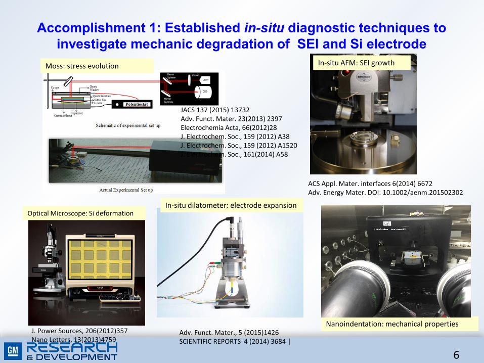
Accomplishment 1: Established in-situ diagnostic techniques to investigate mechanic degradation of SEI and Si electrode
Moss: stress evolution In-situ AFM: SEI growth
Optical Microscope: Si deformation
Nanoindentation: mechanical properties
In-situ dilatometer: electrode expansion
JACS 137 (2015) 13732Adv. Funct. Mater. 23(2013) 2397Electrochemia Acta, 66(2012)28J. Electrochem. Soc., 159 (2012) A38J. Electrochem. Soc., 159 (2012) A1520J. Electrochem. Soc., 161(2014) A58
J. Power Sources, 206(2012)357Nano Letters, 13(2013)4759
Adv. Funct. Mater., 5 (2015)1426SCIENTIFIC REPORTS 4 (2014) 3684 |
ACS Appl. Mater. interfaces 6(2014) 6672Adv. Energy Mater. DOI: 10.1002/aenm.201502302
6

Accomplishment 2: Established a model system combined with in situ AFM and simulations to investigate SEI failure mechanisms
Li segregation at Si/Cu interface leads to the patterned Si slide, which creates an ideal system for investigating the mechanical stability of SEI on Si with large deformation.
0(
Z+P*4&%+(M4%"=?(X*'%"<*8)I(KLa,(/2]/221.*%46]12/-21321(

Accomplishment 2.1: Identified SEI failure mechanism at initial stage via in-situ AFM
in-situ electrochemical AFMcapacity losses from Si pattern and continuous film
Both electrochemical test and in-situ AFM indicate the SEI failure occurs during the lithiation stage
Cracking Buckling Delamination/Spallation
8

Identified SEI failure mechanism at initial stage via in-situ AFM
Cracking Buckling Delamination/Spallation 10 𝜇𝜇𝜇𝜇
1. During 1st cycle lithiation, tensile stress in the SEI (due to expansion of Si) leads tothrough-thickness cracking;
2. These cracks dynamically evolve as cycling continues, and eventually reach to theinterface of SEI and lithiated Si;
3. With further cycling, these cracks deviate towards SEI/LixSi interface and result intospallation of SEI.
9

Surface cracking of SEI near the edge of the island
Lateral expansion: 1.0 μm
SEI
a-Si
Cu current collector
Center of the island (symmetric) Tensile in-plane stress near the edge
sliding zone
6.2 um from top
6.7 um from top
Surface cracking has been observed in the region that SEI is under tension.
If surface crack penetrates the SEI layer, it cannot go across the SEI/Si interface and propagate in the a-Si island under compression.We calculated the energy release rate of the SEI surface crack to investigate the energetically favorable path for crack propagation.
10
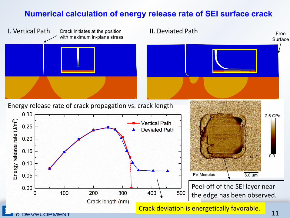
Numerical calculation of energy release rate of SEI surface crack
I. Vertical Path II. Deviated Path
Energy release rate of crack propagation vs. crack length
Peel-off of the SEI layer near the edge has been observed.
Crack deviation is energetically favorable.
Crack initiates at the position with maximum in-plane stress
Free Surface
11

Potential SEI failure mode induced by Si plastic ratcheting
(a) Schematic of the finite element model; (b) Snapshots of the finite element results upon 1st cycle and 4th cycle
Snapshots of the molecular dynamics model before 1st cycle and after 50th cycle.
Upon cycling, a ratcheting mechanism of accumulative plastic deformation in the a-Si has been observed, leading to the gradual wrinkling and eventual SEI delamination.
12

Accomplishment 2.2: Identified SEI failure mechanism at initial stage via modeling
Broken Shell Cracked Shell Mechanically Intact Shell
4.5Å SiO2
2.5Å Al2O3
2.5Å SiO2
7.5Å SiO2
4.5Å Al2O3
Reactive MD simulations show SEI coating failure mechanisms during lithiation.
SEI coating delamination during fast delithiation rate. Design criteria
Continuously remove Li from the coating, followed by different MD relaxation time.
Li0.15Si Li0.75Si
Fast Rate (100x)Slow RateMore Li was trapped in Si. Coating delamination is observed.
13

F',2/#+3%BK7%%
X%/-)/()*'+,-)%9(5-'(%/0/3#)G%
X%/-)/()*'+,-)%+^('%/0/3#)G%
AMa/( 32:( 32:(
AMa1( R:( -:(
AMa3( k/:( k/:(
:_N%&'-/($$%*-%6#6#/%'(+3%BK7%
`#G"('%Y#X%/-)*()*%
B@'5+/(%6-'&"-3-G#($%-5%B#%(3(/*'-.(%+^('%aS%/0/3($%
;<=>%"(C<O('%4'(8%*+)('#("#ED)'(AMa(*4+(E%e%"(&?&8%(%F&<%4&?(
T*4#(C%e%")(12/RI(/R(c3dI(77(12//l12/R(
Y-4('%Y#X%/-)*()*%W-@G"('%$@'5+/(%.@(%*-%BK7%5-'6+,-)%
Accomplishment 3: Identified desirable components in SEI enabling high cycle efficiency
/5(

Synergetic Effects of Inorganic Components in SEI
T*4#(C%e%")(12/RI(/R(c3dI(77(12//l12/R(
•! G>%(<4'%"B*&%)(E%'@%%4(C<1NL3(*4+(C<O(*"%(+%B%&[P%]((
•! ;<=>(B"*&[#4(#B('>%(<4'%"B*&%)(8%*+('#(6#"%(<)#'#7%)(%b&>*4=%)](
;Y(GMX(( RC<(<)#'#7%(%b&>*4=%)(6%*)D"%+(E?(G#OWAaX)(
/-(

Space charge layer near the interface facilitates Li ion transport
/R(
TV! 7-)#/%/+''#('%+//@6@3+,-)%)(+'%*"(%#)*('5+/(%#6&'-M($%*"(%'+*(%&('5-'6+)/(%-5%*"(%(3(/*'-.(b%RV! K3(/*'-)%.(&3(,-)%)(+'%*"(%#)*('5+/(%&'-M#.($%+%9(c('%&+$$#M+,-)%*-%+M-#.%+..#,-)+3%
(3(/*'-30*(%.(/-6&-$#,-)V%
Li2CO3LiF
xx = 0
∆φ
cLi•i
cV �Li
c∞Li•i
c∞V �Li
Li•
!µi (x) = µi (x)+ zie!!! (x) = 0
Z'(%mD<8<E"<D6I('>%()D6(#B(%8%&'"#&>%6<&*8(7#'%4[*8(<)(D4<B#"6(*&"#))('>%(<4'%"B*&%(
!! = !Li2CO3" #!LiF
" = 0.95V
B&+/(%/"+'G(%&-*(),+3<%

Tune grain size and ratio to achieve high ionic conductivity in multi-component solid electrolyte
2-D illustration of the topology of the designed SEI structure for optimized ionic conductivity. A: Li2CO3; B: LiF;
The increment of ionic conduction for different Li2CO3/LiF coating with different volumetric ratio and grain size
ACS Applied Materials & Interfaces, 8 (8), 5687-5693
Grain size effect
17

Explore multi-component SEI with high ionic conductivity
Li diffused into and through SiO2 layer on Si
Li cannot diffuse through LiF layer to Si
ReaxFF parameters were developed for Li-Si-O-Al and Li-Si-O-F systems, allowing us to explore mixed coating materials
Adv. Funct. Mater. 2012, 22, 1145–1149
18

Accomplished 4: Achieved high current efficiency of Si based electrode with optimized SEI/Si electrode system
0 50 100 150 2000.0
0.5
1.0
1.5
2.0
Cycle index
spec
ific
capa
city
(Ah/
g)
94
95
96
97
98
99
100
101
CE
(%)
94.5%
Half cell Full cell, Si electrode paired with HENMC
With the optimized SEI formation and electrolyte additives (FEC), the high cycle efficiency can be achieved (>99.8% with first cycle CE>94%)
0 100 200 300 4000
1
2
3
4
5
6
cycle index
Area
l cap
acity
(mAh
/cm
2 )
98.0
98.5
99.0
99.5
100.0
100.5
CE
19

Summary• Identified functions of individual component in nature SEI, LiF is critical for
stabilizing the SEI layer and improving the cycling efficiency, due to the electricalinsulating and mechanical protection.
• Demonstrated the synergetic effects of LiF and Li2CO3interfaces, which not onlyfacilitate Li ion transport, but also further enhance the passivation function tosuppress electrolyte decomposition.
• By using combined in-situ electrochemical experiments and modelingtechniques, we were able to identify SEI failure modes, which is mainly due tothe fracture during the lithiation process of Si active materials.
• With the optimized SEI formation protocols and electrolyte additives (FEC), thehigh cycle efficiency can be achieved (>99.8% with first cycle CE>94%)
20

Collaborations and Coordination with Other Institutions
Apply advanced binders to improve electrode integrity, also characterize their mechanical properties utilizing the in-situ electrochemical approaches developed in this project;
Investigate the stability of artificial SEI on Si nanoparticles using in-situ TEM;
Investigate the mechanical properties of advanced surface coating as artificial SEI utilizing in-situ electrochemical approaches and modeling;
Conduct large scale ab initio MD simulation of electron transport through ALD coatings to predict electrolyte reduction reactions rates;
Conduct interface modeling for Si-CNT bead-string nano-structures;
Develop novel Si nanostructure, leveraged by Canada NSERC CRD funding and GM support.
21

Responses to Previous Years Comments
• The reviewer stated that ALD coating definitely improves the stability of the Si anode and more experiments are needed rather than just performing
computation.
– The team has conducted a series of experiments and published a few papers (Adv Mater. 23(2011)3911, J. Phys. Chem. 116(2012)1472) . The
purpose of the simulation is to fundamentally understand the mechanism on how ALD coating improves the mechanical stability of SEI and Si
electrode. Based on this, the team will further develop ALD coating to improve the cycle efficiency as reviewer suggested.
• The reviewer stated that the technical progress that has been made so far is impressive. However, it is unclear if the milestone of comparing the
modeling results of SEI deformation and stability with in situ multi beam optical stress sensor (MOSS) measurement has completed or not.
– Following reviewer’s comments, the work has been conducted and the results are being summarized.
• The reviewer explained that the combined DFT and continuum model has been developed to predict the mechanically stable Si-C core-shell structures,
which stabilize the SEI layer and accommodate the volume expansion of Si. However, how the Si-C yolk stability is better than the Si-C core shell
structure, needs to be explained.
– The York-shell structure will provide a free space to accommodate Si volume expansion, and the majority of SEI will form on C shell which has
much less volume expansion, comparing to the large volume expansion from core-shell structure. Therefore, the SEI formed on York-shell
structure will be much stable, leading to better cycle efficiency.
• The reviewer noted that more experiments are recommended rather than computation work.
– More experimental results have been included in the presentation, as the reviewer suggested.
22

Future Plans
• Design a practically useful Si electrode where degradation of the SEI layeris minimized during lithiation and delithation.
• Construct an artificial SEI design map for Si electrodes, based on criticalmechanical and transport properties of desirable SEI for a given Siarchitecture.
• A validated design guidance on how to combine the SEI coating with avariety of Si nano/microstructures. Make Go/No-Go decision based on ifthe modelling guided electrode design can lead to high columbic efficiency>99.9%
23

Acknowledgement
• We acknowledge Tien Duong and the support from DoE, Office of Vehicle Technologies , under the Batteries for
Battery Materials Research(BMR) Program;
• We also acknowledge the graduate students and postdocs involved in this work:
– Ravi Kumar, Qinglin Zhang, Jie Pan, Sung-Yung Kim, Kai Guo, Anton Tokranov, Ill Ryu, Jae-ha Woo
• Dr. Peng Lu for TOF-SIMS, Dr. Mei Cai and Dr. Mark W. Verbrugge for the support.
24

Backup Slides
25

Voltage-dependent defect formation
LiF coated on anodes
σ ≈ 10-31 S/cm
Li2CO3 coated on anodes
Anode
VLi- VF
+
Anode
Lii+ e-
σ ≈ 10-8 S/cm
What will happen if LiF and Li2CO3 coexist in the SEI on anodes?
J. Pan, Y. T. Cheng and Y. Qi, Phys. Rev. B 91 (13), 134116 (2015).26

Established experimental methods to decouple volume change
caused by SEI formation and lithiation of Si
Configuration to measure SEI growth on Cu
Configuration to measure SEI growth on Si (corrected for
growth on Cu)
In Situ AFM and in-situ stress sensor
SEI Thickness + Irreversible Si expansion
SEI formation begins at 0.6V
Stress relaxes through plastic flow to a certain level
27

An Expanded Model of Initial SEI Formation
SEI growth with a fast first cycle: organic SEI does not have time to form instead creating inorganic passivation which prevents further organic SEI from forming. This SEI keeps increasing in thickness, over several cycles.
ACS Appl Mater & Interfaces (2014).
SEI growth with a slow first cycle: Initially organic SEI formed and grown, then inorganic SEI filled in the organic SEI at lower potential which allows Li ion diffusion, eventually most of the SEI is composed of inorganic materials.
28

Understanding interfacial sliding in patterned Si model system
No surface segregation
Li segregation at LixSi/Cu interface
Li15Si4
Cu
Cu current collectorThin film Si negative electrode
a-SiSi/Cu interface
Method: Ab initio MD simulations Results: Li segregation due to charge transfer from Li to Cu..
Method: TOF-SIMS depth profileResults: High Li/Si ratio at the Si/Cu interface
ExperimentsModeling
• Adhesion strength is reduced from 1.85 to 1.53 J/m2 after full lithiation.• Interface sliding resistance is reduced from 0.28 to 0.03 GPa upon full lithiation • Stress buildup is released by interfacial sliding.
Nano Letters, 13 (10), 4759 (2013)
29


![Cleaning Before Coating - SMTA · Deposition Me Men+ + ne* ne* + Men+ Me ... PU-coating AY-coating , Wax coating ed m 2] ... Cleaning Before Coating](https://img.dokumen.tips/doc/110x75/5ad9e7b37f8b9a53618bdbed/cleaning-before-coating-smta-me-men-ne-ne-men-me-pu-coating-ay-coating.jpg)