Embed Size (px)
Citation preview

Progress In Electromagnetics Research, PIER 84, 333–348, 2008
A CIRCULARLY POLARIZED QUASI-LOOP ANTENNA
C.-J. Wang and C.-H. Lin
Department of Electronics EngineeringNational University of TainanTainan 700, Taiwan
Abstract—This paper presents a circularly polarized (CP) GPS/DCSloop-like antenna with a microstrip feed. The proposed antennacomprised of a quasi-C antenna, an inverted-L sleeve strip connectedwith the ground plane and an L-shaped slit embedded in the groundplane. The C-like antenna generates a resonant mode with a poorimpedance matching condition. The inverted-L grounded strip andthe embedded L-slit are not only capable of modifying two orthogonalelectric fields with equal amplitude and phase difference of 90 degreefor radiating circular polarization at 1.575 GHz, but the impedancecharacteristics is also improved and the operating frequency is reduced.Both simulated and measured results are provided to validate theimpedance and CP performance of the proposed antenna. For theoptimized antenna case, the measured bandwidth with an axial ratio(AR) of less than 3 dB is larger than 19% and the measured impedancebandwidth of reflection coefficient S11 < −10 dB is about 30.1%.
1. INTRODUCTION
Satellite communications have been extensively used for the datatransmission, such as the voice or image. Recently, the globalpositioning system (GPS) has found increasingly many commercialapplications since [1, 2] the 1980’s release of the coded informationtransmitted by the US Department of Defense satellites. As knownthat the Faraday rotation effect [3] causes the linear-field vectors torotate as a consequence of interaction with static magnetic fields alongthe propagation path. To reduce the polarization mismatch, antennaswith circular polarization (CP) can be used for the GPS applicationsand the GPS antennas cover the frequency band of 1575 ± 2 MHz.
Due to low profile, low cost, light weight, wide bandwidth andeasy integration with other devices, the planar monopole antenna is

334 Wang and Lin
widely used for the wireless communication systems, such as GSM,DCS, CDMA, WLAN and UWB systems [4–12]. As well known, themicrostrip monopole antenna can only radiate the linearly polarized(LP) wave with wideband bandwidth. Until to now, few studies of thecircularly-polarized monopole antenna have been investigated. Thedesign of the slitted ground has been proposed for the band-notchfunction of the UWB monopole antenna [13]. By simply embeddinga small rectangular slit in the ground plane, a notched band can beachieved. In the past, we have proposed a microstrip monopole antennawith circular polarization and linear polarization by combining themonopole antenna and the inverted-L strip [14]. The CP radiationwave at 1.575 GHz is excited by the loop mode and the LP radiationwave at 1.8 GHz is excited by the monopole mode. However, theCP performance is not easy to achieve by tuning the geometricalparameters of the antenna.
In this paper, we present a microstrip-fed circularly-polarizedloop-like antenna which meets the requirements of both a digitalcommunication system and a global positioning system. Based on thestudies in [14], by utilizing the coupling effect between the monopoleantenna and sleeve, the excited resonant mode can be changed to theloop mode, a traveling-wave mode. The phase difference of 90 degreefor the orthogonal electric fields is derived by embedding the slit inthe ground plane and the CP radiation can be easily achieved. Themeasured and simulated results of S11 and AR agree well. The designprocedures are presented.
2. ANTENNA DESIGN
Figure 1 shows the schematic diagram of the proposed CP GPS/DCSantenna. The proposed antenna configuration consists of a C-likemonopole, one sleeve and one slit. The antenna is printed on anFR4 microwave substrate with thickness of 1.6 mm and relativelypermittivity of 4.4. A 50-Ω microstrip-fed line with a width (Wt =3 mm) is used to excite the antenna. An impedance transformeris inserted between the monopole antenna and the feeding line.Impedance matching is also optimized by cutting the copper groundplane. The C-like monopole is centrally placed at the end of themicrostrip feeding line and the length of the monopole antenna isdetermined by a quarter wavelength at 2 GHz. Due to the interactionbetween the monopole and the ground plane, the length will decrease.Because of the bent structure, the impedance matching condition ispoor. As similar as the design of adding a shorted parasitic wire [15],we add an inverted-L strip on the right side of the ground plane in

Progress In Electromagnetics Research, PIER 84, 2008 335
Figure 1. Schematic configuration of the proposed antennas.
order to improve the impedance characteristics. At the GPS band, themonopole and the inverted-L sleeve can be treated as the rhombic hulahoop [16], and the proposed antenna can have the current distributionof traveling-wave type on the loop, which has approximately a constantamplitude and linearly changing phase. The current distribution ischanged by modifying the geometrical dimensions of the gap betweenthe monopole and sleeve. To improve the phase difference of the twoorthogonal electric fields and achieve the better circular polarization,an L-shaped slit is embedded in the ground plane on the left sideof the feeding line. The slit width (S) is 1 mm. By tuning thegeometrical parameters of the antenna, the characteristic parameterssuch as reflection coefficient (S11) and axial ratio (AR) of the proposedantenna have been compared in order to optimize the antenna. Table1 gives the geometrical parameters for the proposed CP quasi-loopantenna after optimization process. The antenna performance for thedifferent topologies of the slit in the ground plane is compared. Finally,the size of the ground plane is tuned to study the effect on S11 andAR.
Table 1. Geometric parameters of the proposed antenna.
Parameter W1a W1b W3 L1 L2a L2b H1 H2 D G1 G2 Lg Wg
Unit(mm) 4.5 2.3 2 15 17 4 8 13 2 6 6 22 80

336 Wang and Lin
-30
-25
-20
-15
-10
-5
0
1 1.5 2 2.5 3Freq (GHz)
S11
(dB
)
C-like monopole
monopole with sleeve
monopole with sleeve and slit
Figure 2. Comparison of the simulated S11 of the three testedantennas.
3. RESULTS
Figure 2 is the comparison of the simulated S11 of three testedmonopole antennas, such as the C-like monopole, the monopolewith the sleeve, and the monopole with the sleeve and slit. Theparameters of the antennas are obtained using Ansoft High-frequencyStructure Simulator (HFSS) simulation software in order to comparethe improvement in the antenna bandwidth and circular polarization.From the results, the C-like monopole radiates little power into thespace due to the poor matching condition at 2.2 GHz. The resonantband at 2.0 GHz can be obtained after adding the inverted-L groundedstrip. The operating frequency is further shifted toward the lowerfrequency as the L-slit is embedded. The designs of the grounded stripand the L-slit also cause an increase in bandwidth, and a decrease inreflection coefficient levels.
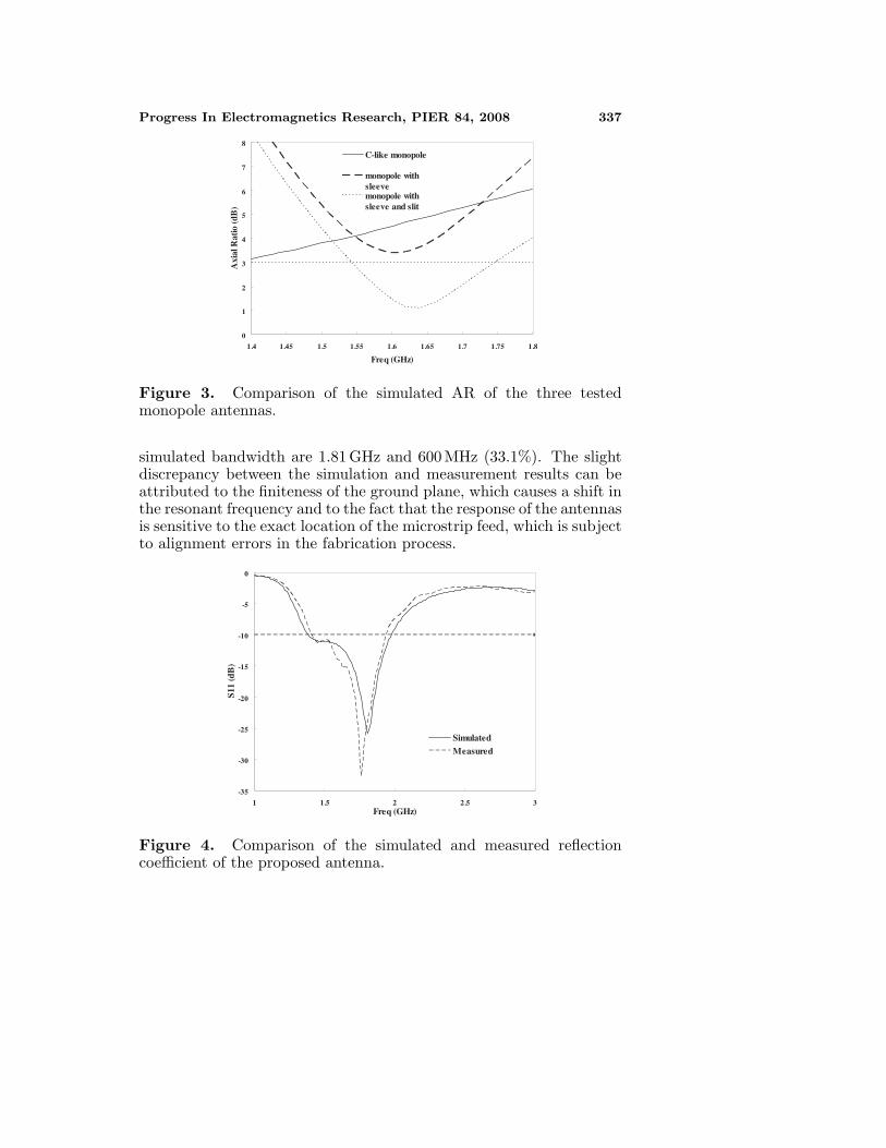
Figure 3 shows the simulated axial ratio (AR) versus operatingfrequency for the three kinds of the above antennas, respectively.Although the AR of the C-like monopole is close to 3 dB, little poweris radiated because of poor impedance matching condition at 1.4 GHz.Tuning of the antenna by use of the sleeve and slit is introduced toimprove the AR and impedance bandwidth characteristics.
Figure 4 shows the simulated and measured reflection coefficient ofthe proposed antenna with the sleeve and slit. As can be observed fromthis figure, the measured center frequency and −10 dB S11 bandwidthare 1.76 GHz and 530 MHz (30.1%), whereas the center frequency and
Progress In Electromagnetics Research, PIER 84, 2008 337
0
1
2
3
4
5
6
7
8
1.4 1.45 1.5 1.55 1.6 1.65 1.7 1.75 1.8
Freq (GHz)
Axi
al R
atio
(dB
)
C-like monopole
monopole withsleevemonopole withsleeve and slit
Figure 3. Comparison of the simulated AR of the three testedmonopole antennas.
simulated bandwidth are 1.81 GHz and 600 MHz (33.1%). The slightdiscrepancy between the simulation and measurement results can beattributed to the finiteness of the ground plane, which causes a shift inthe resonant frequency and to the fact that the response of the antennasis sensitive to the exact location of the microstrip feed, which is subjectto alignment errors in the fabrication process.
-35
-30
-25
-20
-15
-10
-5
0
1 1.5 2 2.5 3Freq (GHz)
S11
(dB
)
SimulatedMeasured
Figure 4. Comparison of the simulated and measured reflectioncoefficient of the proposed antenna.
338 Wang and Lin
0
1
2
3
4
5
6
7
8
9
1.4 1.45 1.5 1.55 1.6 1.65 1.7 1.75 1.8 1.85 1.9Freq (GHz)
Axi
al R
atio
(dB
)
Measured
Simulated
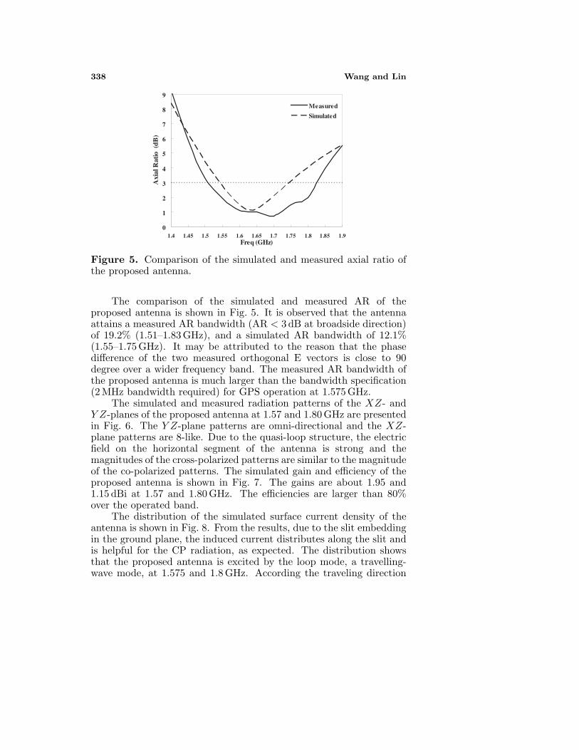
Figure 5. Comparison of the simulated and measured axial ratio ofthe proposed antenna.
The comparison of the simulated and measured AR of theproposed antenna is shown in Fig. 5. It is observed that the antennaattains a measured AR bandwidth (AR < 3 dB at broadside direction)of 19.2% (1.51–1.83 GHz), and a simulated AR bandwidth of 12.1%(1.55–1.75 GHz). It may be attributed to the reason that the phasedifference of the two measured orthogonal E vectors is close to 90degree over a wider frequency band. The measured AR bandwidth ofthe proposed antenna is much larger than the bandwidth specification(2 MHz bandwidth required) for GPS operation at 1.575 GHz.
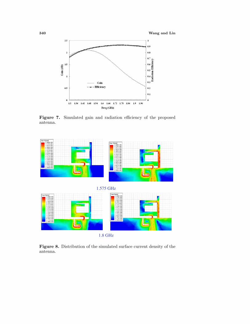
The simulated and measured radiation patterns of the XZ- andY Z-planes of the proposed antenna at 1.57 and 1.80 GHz are presentedin Fig. 6. The Y Z-plane patterns are omni-directional and the XZ-plane patterns are 8-like. Due to the quasi-loop structure, the electricfield on the horizontal segment of the antenna is strong and themagnitudes of the cross-polarized patterns are similar to the magnitudeof the co-polarized patterns. The simulated gain and efficiency of theproposed antenna is shown in Fig. 7. The gains are about 1.95 and1.15 dBi at 1.57 and 1.80 GHz. The efficiencies are larger than 80%over the operated band.
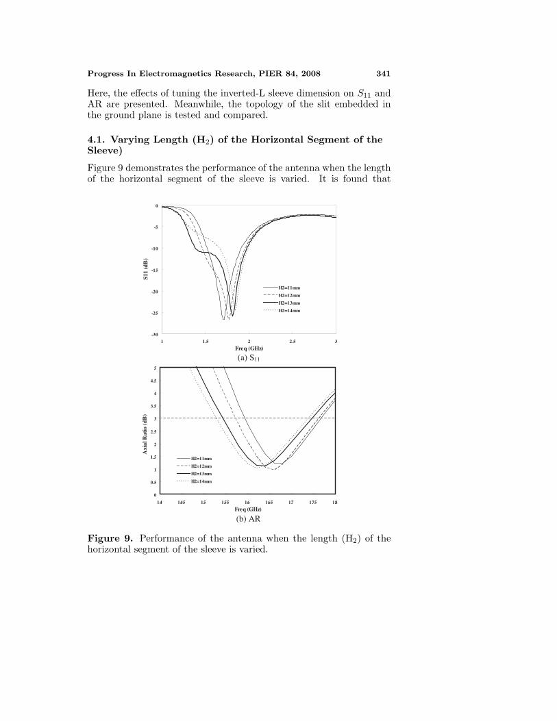
The distribution of the simulated surface current density of theantenna is shown in Fig. 8. From the results, due to the slit embeddingin the ground plane, the induced current distributes along the slit andis helpful for the CP radiation, as expected. The distribution showsthat the proposed antenna is excited by the loop mode, a travelling-wave mode, at 1.575 and 1.8 GHz. According the traveling direction

Progress In Electromagnetics Research, PIER 84, 2008 339
YZ-plane, 1.575 GHz XZ-plane, 1.575 GHz
YZ-plane, 1.8 GHz XZ-plane, 1.8 GHz
Figure 6. Simulated and measured radiation patterns of the XZ- andY Z-plane of the proposed antenna at 1.575 and 1.8 GHz.
of the simulated surface current, the type of the circular polarizationof the proposed antenna is left-hand. However, the right-hand circularpolarization can be derived by moving the sleeve to the left side of theground plane and reversing the C-like antenna and the sleeve.
4. PARAMETRIC STUDY
In the previous sections, the performance of the CP quasi-loop antennais presented. It is of practical interest to investigate the antennaperformance when some of the geometrical parameters are changed.
340 Wang and Lin
Figure 7. Simulated gain and radiation efficiency of the proposedantenna.
1.575 GHz
1.8 GHz
Figure 8. Distribution of the simulated surface current density of theantenna.
Progress In Electromagnetics Research, PIER 84, 2008 341
Here, the effects of tuning the inverted-L sleeve dimension on S11 andAR are presented. Meanwhile, the topology of the slit embedded inthe ground plane is tested and compared.
4.1. Varying Length (H2) of the Horizontal Segment of theSleeve)
Figure 9 demonstrates the performance of the antenna when the lengthof the horizontal segment of the sleeve is varied. It is found that
-30
-25
-20
-15
-10
-5
0
1 1.5 2 2.5 3
Freq (GHz)
S11
(dB
)
H2=11mm
H2=12mm
H2=13mm
H2=14mm
(a) S11
0
0.5
1
1.5
2
2.5
3
3.5
4
4.5
5
1.4 1.45 1.5 1.55 1.6 1.65 1.7 1.75 1.8
Freq (GHz)
Axi
al R
atio
(dB
)
H2=11mm
H2=12mm
H2=13mm
H2=14mm
(b) AR
Figure 9. Performance of the antenna when the length (H2) of thehorizontal segment of the sleeve is varied.

342 Wang and Lin
changing the length could give frequency-moving effect to the antenna’sS11 and AR bandwidths. It is observed that the impedance frequency,power level and AR bandwidth increase when the length varies from11 to 14 mm. On the other hand, the impedance bandwidth and ARfrequency decreases. In order to cover the operating frequency at theGPS band, length of H2 is set to 13 mm.
4.2. Varying Open-stub Length (L2b)
Figure 10 shows the comparison of S11 and AR of the antenna whenthe length of the open stub connecting with the sleeve is varied.As shown in the figure, the bandwidth and reflection coefficientlevel can be controlled by varying L2b. It has significant effect onthe impedance matching condition around 1.5 GHz. The reflectioncoefficient at the GPS band (1.575 GHz) is improved when increasingthe length. Moreover, as L2b is increased to 4 mm, the lower-band-edge frequency (when S11 = −10 dB) decreases and the impedancebandwidth is increased by 57.9%. The reason of the bandwidthenhancement may be that the capacitance of the open stub cancelspart of the inductance resulting from the thin antenna trace. At L2b
equal to 6 mm, the impedance characteristics become undesired andthe impedance bandwidth decreases again.
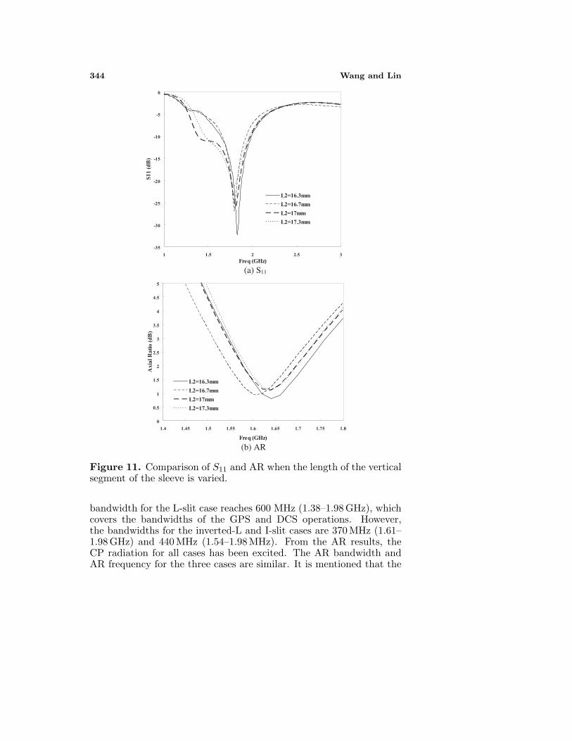
4.3. Varying Length (L2a) of the Vertical Segment
Figure 11 shows the comparison of S11 and AR when the length of thevertical segment of the sleeve is varied. From the simulated impedancecharacteristics (S11), it is observed that the sleeve not only resultsin the CP performance but also affects the impedance bandwidth,especially at the GPS band. Although the axial ratio for the caseof L2a = 17.3 mm is more suitable for the CP performance at theGPS band, the impedance bandwidth does not cover the required band(1575 ± 2 MHz) for the GPS application.
4.4. Replacing the Slit Topology
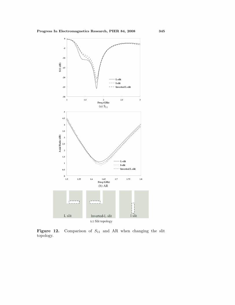
Figure 12 shows the comparison of the simulated reflection coefficientand axial ratio of the quasi-loop antenna when changing the slittopology. The three slit topologies, including the L-slit, the inverted-L-slit and the I-slit, are shown in Fig. 12(c). The dimensions of theC-like monopole and inverted-L sleeve are fixed to the same values inTable 1. From the results of impedance characteristics, the lower-band-edge frequency, impedance matching condition and power level of theL-slit case are superior to the other cases. The obtained impedance

Progress In Electromagnetics Research, PIER 84, 2008 343
-35
-30
-25
-20
-15
-10
-5
0
1 1.5 2 2.5
Freq (GHz)
S11
(dB
)
3
L2b=0mm
L2b=2mm
L2b=4mm
L2b=6mm
(a) S11
0
1
2
3
4
5
6
1.5 1.55 1.6 1.65 1.7 1.75 1.8
Freq (GHz)
Axi
al R
atio
(dB
)
L2b=0mm
L2b=2mm
L2b=4mm
L2b=6mm
(b) AR
Figure 10. Comparison of S11 and AR of the antenna when the length(L2b) of the open stub is varied.
344 Wang and Lin
-35
-30
-25
-20
-15
-10
-5
0
1 1.5 2 2.5 3Freq (GHz)
S11
(dB
)
L2=16.3mm
L2=16.7mm
L2=17mm
L2=17.3mm
0
0.5
1
1.5
2
2.5
3
3.5
4
4.5
5
1.4 1.45 1.5 1.55 1.6 1.65 1.7 1.75 1.8
Freq (GHz)
Axi
al R
atio
(dB
)
L2=16.3mm
L2=16.7mm
L2=17mm
L2=17.3mm
(a) S11
(b) AR
Figure 11. Comparison of S11 and AR when the length of the verticalsegment of the sleeve is varied.
bandwidth for the L-slit case reaches 600 MHz (1.38–1.98 GHz), whichcovers the bandwidths of the GPS and DCS operations. However,the bandwidths for the inverted-L and I-slit cases are 370 MHz (1.61–1.98 GHz) and 440 MHz (1.54–1.98 MHz). From the AR results, theCP radiation for all cases has been excited. The AR bandwidth andAR frequency for the three cases are similar. It is mentioned that the
Progress In Electromagnetics Research, PIER 84, 2008 345
-30
-25
-20
-15
-10
-5
0
1 1.5 2 2.5 3Freq (GHz)
S11
(dB
)
L-slit
I-slit
Inverted L-slit
0
0.5
1
1.5
2
2.5
3
3.5
4
4.5
5
1.5 1.55 1.6 1.65 1.7 1.75 1.8
Freq (GHz)
Axi
al R
atio
(dB
)
L-slit
I-slit
Inverted L-slit
(a) S11
(b) AR
(c) Slit topology
Figure 12. Comparison of S11 and AR when changing the slittopology.

346 Wang and Lin
-30
-25
-20
-15
-10
-5
0
1 1.5 2 2.5Freq (GHz)
S11
(dB
)
3
Wg=60mm
Wg=80mm
Wg=100mm
(a) S11
0
2
4
6
8
10
12
14
16
18
20
1.4 1.45 1.5 1.55 1.6 1.65 1.7 1.75 1.8Freq (GHz)
Axi
al R
atio
(dB
) Wg=60mm
Wg=80mm
Wg=100mm
(b) AR
Figure 13. Comparison of S11 and AR of the antenna when the length(Wg) of the ground plane is varied.
slit-embedding design may be a useful and stable method to excitethe CP performance of the microstrip monopole antenna or the loopantenna.
4.5. Tuning the Size (Wg) of the Ground Plane
Figure 13 shows the comparison of S11 and AR of the antenna whenthe length (Wg) of the ground plane is varied. From the figures, it is

Progress In Electromagnetics Research, PIER 84, 2008 347
found that the ground plane plays an important role on the radiation.The operated frequency of the antenna decreases when increasing thelength. The improvement of the impedance bandwidth can be achievedby tuning the dimension of the ground plane.
5. CONCLUSION
This paper presents a circularly polarized loop-like antenna designwith good performance for the applications of the GPS and DCS. Byadding an inverted-L sleeve at the ground plane and tuning the gapdimensions, the loop mode can be excited. The CP performance iseasily improved by embedding the slit in the ground plane. Futureresearch will be studied in order increase the impedance bandwidthcovering the CDMA operation.
ACKNOWLEDGMENT
The research described here was carried out at the RF Circuit andAntenna Laboratory, National University of Tainan, under the Grants:NSC 96-2221-E-024-001 of the National Science Council, Taiwan.Support of the simulation tools from the National Center for HighPerformance Computing, Hsinchu, Taiwan is also acknowledged.
REFERENCES
1. Koo, J. C., J. Shim, T. I. Suh, J. K. Bang, and H. T. Kim, “Sizeoptimization of a microstrip GPS antenna for automobile glasswith a genetic algorithm,” Journal of Electromagnetic Waves andApplications, Vol. 18, 1459–1470, 2004.
2. Chou, H. T., L. R. Kuo, and W. J. Liao, “Characteristic evaluationof an active patch antenna structure with an embedded LNAmodule for GPS reception,” Journal of Electromagnetic Wavesand Applications, Vol. 21, 599–614, 2007.
3. Johnson, R. C. and H. Jasik, Antenna Engineering Handbook,McGraw-Hill, New York, 1984.
4. Chen, Z. N., M. J. Ammann, M. Y. W. Chia, and T. S. P. See,“Annular planar monopole antennas,” IEE Proc. — Microw.Antennas Propag., Vol. 149, No. 4, 200–203, Aug. 2002.
5. Liu, W. C., W. R. Chen, and C. M. Wu, “Printed double S-shaped monopole antenna for wideband and multiband operationof wireless communications,” IET Microwave, Antennas andPropagation, Vol. 151, No. 6, 473–476, Dec. 2004.
348 Wang and Lin
6. Lin, C. C., Y. C. Kan, L. C. Kuo, and H. R. Chuang, “Aplanar triangular monopole antenna for UWB communication,”IEEE Microw. Wireless Compon. Lett., Vol. 15, No. 10, 624–626,Oct. 2005.
7. Ray, K. P. and Y. Ranga, “Ultra-wideband printed modifiedtriangular monopole antenna,” Electron. Lett., Vol. 42, No. 19,1081–1082, Sep. 2006.
8. Liu, W. C. and C. F. Hsu, “CPW-FED notched monopoleantenna for UMTS/IMT-2000/WLAN applications,” Journal ofElectromagnetic Waves and Applications, Vol. 21, 841–851, 2007.
9. Ren, W., J. Y. Deng, and K. S. Chen, “Compact PCB monopoleantenna for UWB applications,” Journal of ElectromagneticWaves and Applications, Vol. 21, 1411–1420, 2007.
10. Gopikrishna, M., D. D. Krishna, A. R. Chandran, andC. K. Aanandan, “Square monopole antenna for ultra wide bandcommunication applications,” Journal of Electromagnetic Wavesand Applications, Vol. 21, 1525–1537, 2007.
11. Zhang, H. T., Y. Z. Yin, and X. Yang, “A wideband monopolewith G type structure,” Progress In Electromagnetics Research,PIER 76, 229–236, 2007.
12. Zaker, R., C. Ghobadi, and J. Nourinia, “Modified microstrip-fed two-step tapered monopole antenna for UWB and WLANapplications,” Progress In Electromagnetics Research, PIER 77,137–148, 2007.
13. Sim, C. Y. D., W. T. Chung, and C. H. Lee, “Novel band-notch UWB antenna design with slit ground plane,” Microw. Opt.Technol. Lett., Vol. 50, No. 8, 2229–2233, Aug. 2008.
14. Wang, C. J. and Y. C. Lin, “A New CPW-fed monopole antennawith both linear and circular polarizations,” IET Microwaves,Antennas & Propagation, Vol. 2, No. 5, 466–472, Aug. 2008.
15. Jan, J. Y. and L. C. Tseng, “Small planar monopole antenna witha shorted parasitic inverted-L wire for wireless communications inthe 2.4-, 5.2-, and 5.8-GHz bands,” IEEE Trans. Antennas andPropag., Vol. 52, No. 7, 1903–1905, Jul. 2004.
16. Morishita, H. and K. Hirasawa, “Wideband circularly-polarizedloop antenna,” Proc. IEEE AP-S Int. Antennas Propag. Symp.,1286–1289, 1994.