Embed Size (px)
Citation preview
A CEWebS Component for Facilitating OnlineCooperative Brainstorming Processes (ChatStorm) andDrawing Activity Diagrams (GraphTalk)
Jürgen Mangler, Christine Bauer
Department of Computer Science and Business InformaticsUniversity of Vienna
Abstract:
Drawing your ideas to a piece of paper is easy, but drawing onto the screen us-ing the mouse appears to be quite complicated. This usually results in some non-formalised, bad-looking scribbling that is hard to extend and which makes it hardto modify or delete fragments.
Currently available web-based whiteboard tools support common drawing features.However, in informatics, teams enjoy the advantage of formalised languages (e.g.UML), which whiteboards do not support and, hence, do not make this advantageeffective.
For supporting brainstorming processes, we developed a simple, extendable chatapplication that can be embedded into existing learning environments through aWeb service framework and focuses on a cooperative modelling approach insteadof cooperative drawing.
Contents:
1 Introduction 3
1.1 Background. . . . . . . . . . . . . . . . . . . . . . . . . . . . . . . . . . . . 3
1.2 Aim . . . . . . . . . . . . . . . . . . . . . . . . . . . . . . . . . . . . . . . . 3
2 Initial Situation 5
3 Improving the Situation 8
3.1 Can Web-based Whiteboards Challenge the Problem?. . . . . . . . . . . . . 9
3.1.1 What are Web-based Whiteboards?. . . . . . . . . . . . . . . . . . . 9
1

3.1.2 Feasibility of Web-based Whiteboards. . . . . . . . . . . . . . . . . . 10
3.2 Our Tool. . . . . . . . . . . . . . . . . . . . . . . . . . . . . . . . . . . . . . 10
3.2.1 Synchronous Diagram Creation Feature. . . . . . . . . . . . . . . . . 11
3.2.2 Chat Facility . . . . . . . . . . . . . . . . . . . . . . . . . . . . . . . 12
4 Requirements and Description of the System 13
4.1 Functional Requirements. . . . . . . . . . . . . . . . . . . . . . . . . . . . . 13
4.2 Non-functional Requirements and Design Decisions. . . . . . . . . . . . . . . 14
5 ChatStorm - Architecture and First Impressions 16
6 Conclusions 19
7 The Client 20
7.1 The Use-Cases. . . . . . . . . . . . . . . . . . . . . . . . . . . . . . . . . . 20
7.2 The Technology. . . . . . . . . . . . . . . . . . . . . . . . . . . . . . . . . . 22
7.3 Creating Symbol Libraries. . . . . . . . . . . . . . . . . . . . . . . . . . . . 23
7.4 Statistics. . . . . . . . . . . . . . . . . . . . . . . . . . . . . . . . . . . . . . 24
7.5 TheSaveFunction . . . . . . . . . . . . . . . . . . . . . . . . . . . . . . . . 25
7.6 The State of The Client. . . . . . . . . . . . . . . . . . . . . . . . . . . . . . 25
8 The Server 26
9 The Interaction With CEWebS 36
10 A Library for Creating BLESS Models 36
11 Thanks And Additional Information 39
2

Figure 1: Distribution of a Software Engineer’s Time
1 Introduction
1.1 Background
In summer term 2004, about 290 students attended the course ”Web Engineering” at our de-partment. In this course students should learn about different types and architectures of WebBased Systems (WBSs) and how to use them. In small-scale teams of 3 to 5, students had togo through the whole process of planning and realising their own small WBS. This processwas loosely based on the Rational Unified Process (RUP) [23] and included the presentationof a vision document, an inception phase in which students specified the basic outlines of theirsystems, an elaboration phase with detailed analysis of their WBSs, and a construction phaseresulting in a fully functional prototype. The whole course was supported by a custom Webservice based platform (see [14, p 20, p 22]). This platform provided students with helpfulresources (e.g. lecture notes, links, etc.), a tool for uploading and sorting students’ contribu-tions, tools for testing the functionality of their home assignments (e.g. XML, DTD, Schema,WSDL), and various communication facilities such as forums and feedback forms.
In the inception phase, one of the suggested steps was the creation of a Rich Picture Diagram(RPD), which resulted directly from a team’s brainstorming process and formed the basis forall architectural decisions that took place later. Although it is quite difficult to assess a non-formalised diagram, we found student’s RPDs quite varying in terms of understandability andefficiency.
1.2 Aim
A typical project is not carried out by an individual but by a closely interacting team. A studyconducted by IBM (see [15]) revealed that about 30% of a typical programmer’s time is used forinteracting with other team members (see Fig.1). This should not be different for web projects.
We wanted to create a realistic setting for our course. Thus, giving our students not only theo-retical and practical knowledge of methodologies and tools used for creating WBSs but also asense of the interaction that is necessary in order to create such systems.
In order to create realistic working conditions, we took a blended learning approach as discussed
3
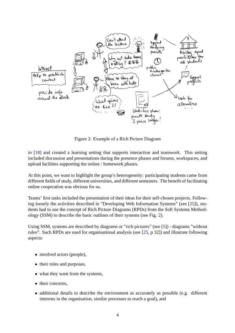
Figure 2: Example of a Rich Picture Diagram
in [18] and created a learning setting that supports interaction and teamwork. This settingincluded discussion and presentations during the presence phases and forums, workspaces, andupload facilities supporting the online / homework phases.
At this point, we want to highlight the group’s heterogeneity: participating students came fromdifferent fields of study, different universities, and different semesters. The benefit of facilitatingonline cooperation was obvious for us.
Teams’ first tasks included the presentation of their ideas for their self-chosen projects. Follow-ing loosely the activities described in ”Developing Web Information Systems” (see [25]), stu-dents had to use the concept of Rich Picture Diagrams (RPDs) from the Soft Systems Method-ology (SSM) to describe the basic outlines of their systems (see Fig.2).
Using SSM, systems are described by diagrams or ”rich pictures” (see [5]) - diagrams ”withoutrules”. Such RPDs are used for organisational analysis (see [25, p 32]) and illustrate followingaspects:
• involved actors (people),
• their roles and purposes,
• what they want from the systems,
• their concerns,
• additional details to describe the environment as accurately as possible (e.g. differentinterests in the organisation, similar processes to reach a goal), and
4
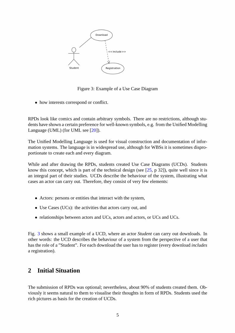
Figure 3: Example of a Use Case Diagram
• how interests correspond or conflict.
RPDs look like comics and contain arbitrary symbols. There are no restrictions, although stu-dents have shown a certain preference for well-known symbols, e.g. from the Unified ModellingLanguage (UML) (for UML see [20]).
The Unified Modelling Language is used for visual construction and documentation of infor-mation systems. The language is in widespread use, although for WBSs it is sometimes dispro-portionate to create each and every diagram.
While and after drawing the RPDs, students created Use Case Diagrams (UCDs). Studentsknow this concept, which is part of the technical design (see [25, p 32]), quite well since it isan integral part of their studies. UCDs describe the behaviour of the system, illustrating whatcases an actor can carry out. Therefore, they consist of very few elements:
• Actors: persons or entities that interact with the system,
• Use Cases (UCs): the activities that actors carry out, and
• relationships between actors and UCs, actors and actors, or UCs and UCs.
Fig. 3 shows a small example of a UCD, where an actorStudentcan carry out downloads. Inother words: the UCD describes the behaviour of a system from the perspective of a user thathas the role of a ”Student”. For each download the user has to register (every downloadincludesa registration).
2 Initial Situation
The submission of RPDs was optional; nevertheless, about 90% of students created them. Ob-viously it seems natural to them to visualise their thoughts in form of RPDs. Students used therich pictures as basis for the creation of UCDs.
5
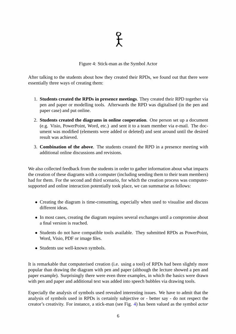
Figure 4: Stick-man as the Symbol Actor
After talking to the students about how they created their RPDs, we found out that there wereessentially three ways of creating them:
1. Students created the RPDs in presence meetings. They created their RPD together viapen and paper or modelling tools. Afterwards the RPD was digitalised (in the pen andpaper case) and put online.
2. Students created the diagrams in online cooperation. One person set up a document(e.g. Visio, PowerPoint, Word, etc.) and sent it to a team member via e-mail. The doc-ument was modified (elements were added or deleted) and sent around until the desiredresult was achieved.
3. Combination of the above. The students created the RPD in a presence meeting withadditional online discussions and revisions.
We also collected feedback from the students in order to gather information about what impactsthe creation of these diagrams with a computer (including sending them to their team members)had for them. For the second and third scenario, for which the creation process was computer-supported and online interaction potentially took place, we can summarise as follows:
• Creating the diagram is time-consuming, especially when used to visualise and discussdifferent ideas.
• In most cases, creating the diagram requires several exchanges until a compromise abouta final version is reached.
• Students do not have compatible tools available. They submitted RPDs as PowerPoint,Word, Visio, PDF or image files.
• Students use well-known symbols.
It is remarkable that computerised creation (i.e. using a tool) of RPDs had been slightly morepopular than drawing the diagram with pen and paper (although the lecture showed a pen andpaper example). Surprisingly there were even three examples, in which the basics were drawnwith pen and paper and additional text was added into speech bubbles via drawing tools.
Especially the analysis of symbols used revealed interesting issues. We have to admit that theanalysis of symbols used in RPDs is certainly subjective or - better say - do not respect thecreator’s creativity. For instance, a stick-man (see Fig.4) has been valued as the symbolactor
6
Figure 5: Comic Figure Lisa Simpson as the Symbol Actor
Figure 6: Stressed Employee as the Symbol Actor
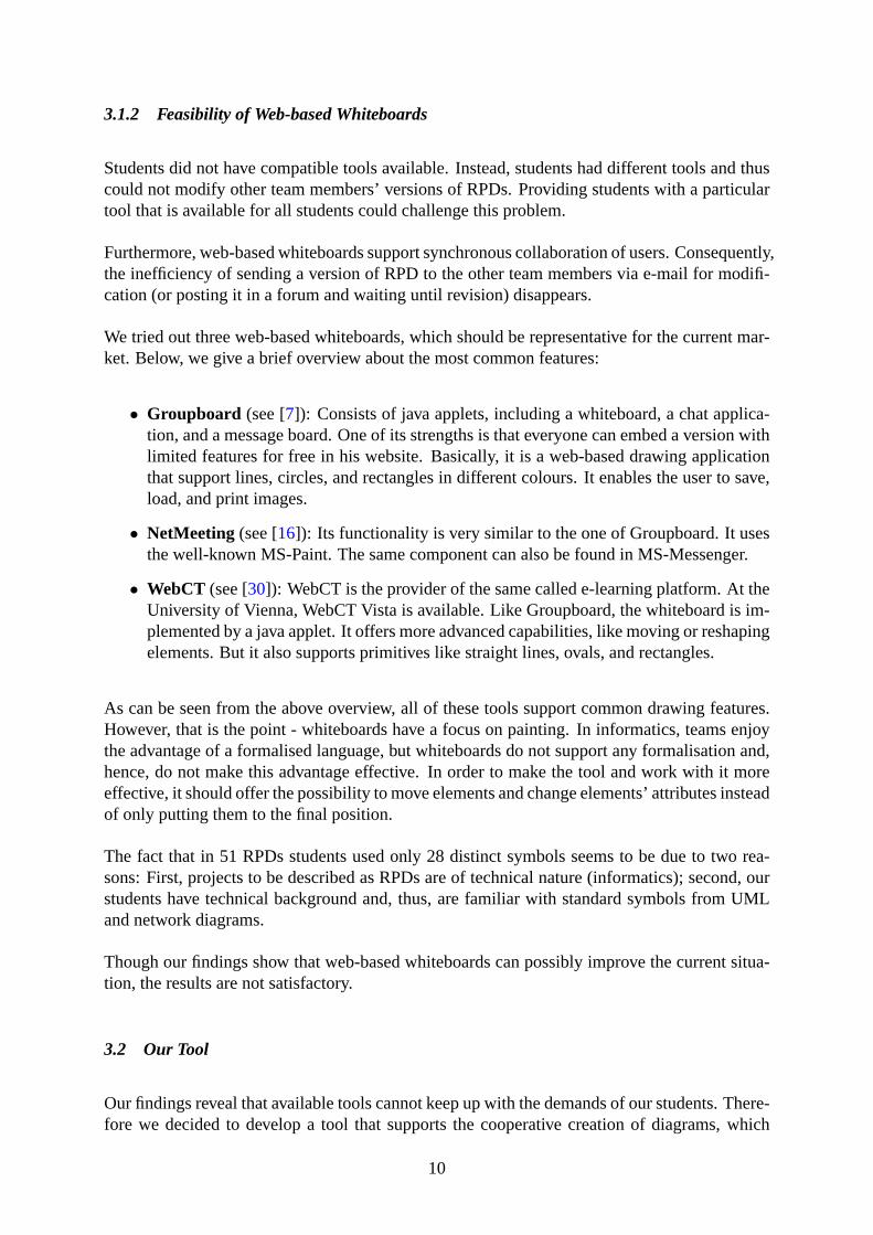
as well as had been the comic figure Lisa Simpson (depicted in Fig.5) or a stressed employee(see Fig.6), which both hold artistic creativity. Nevertheless, we could identify that among thetotal number of 51 submitted RPDs, only 28 distinct symbols were used (see Fig.7).
In essence, we can summarise following aspects that seem interesting to us and are worth men-tioning:
• Most students, especially when using pen and paper, used well-known symbols, e.g. theactor symbol from UML and symbols from network diagrams including computers, net-work clouds, buildings, storage, and telephone symbols.
• The preference for Use Cases was more a textual than a directly visual one. The studentsused phrases that they could directly reapply to UCs - and did so. In our opinion, thismay be due to two reasons:
– Students created the well-known UCs before the RPDs (which were in fact new tomost of them), and only summarised their UCs as RPDs afterwards.
Figure 7: Symbols Used by the Web-Engineering Students
7
– Students used their RPDs as intended to analyse the whole system, to ease the cre-ation of detailed Use Cases but are influenced by their knowledge about UCDs.
• The students did not use different kinds of arrows for describing relationships betweensymbols although they should know different connection types very well (e.g. fromUML). They only used ordinary solid line arrows, sometimes with a caption.
• Visual quality of RPDs submitted varied a lot. The visual representations reveal whatstudents had in mind when creating their RPDs (which ranges fromI have to do it, but Ido it fastto RPDs are indeed a good idea).
• RPDs realised with pen and paper used symbols that were easier to understand. Thereforethey were overall more comprehensible.
• The diagrams made in Word, PowerPoint and Visio sometimes showed excessive use ofClipArts, which leads to a cluttered appearance (photos of persons or comic figures werenot immediately recognisable as actors).
• The diagrams done with ordinary drawing tools resembled the style of the pen and paperversion presented in the lecture but suffered from a lack of completeness; they generallyconsisted of basic elements only.
3 Improving the Situation
Analysis of the is-situation shows that 24 teams (47.06%) used pen and paper for realising theirRPDs while 27 teams (52.94%) made use of a modelling tool. Albeit, the analysis reveals thatstudents realised their RPDs mainly in presence meetings. Main reason for this seems to be thatonline cooperation would have been cumbersome and complicated. This assumption is affirmedby students’ reactions. The tenor can be summarised as follows:
• We tried to make our diagram in online cooperation but we were simply unable becausebecause we lacked in a tool that anyone of our team could install on his computer.
• A lot of discussion was necessary in order to put down the RPD in a version we all couldagree on. Exporting files and sending them via e-mail or posting them in a forum hadbeen exhausting.
• We agreed to take the effort to meet personally since, for us, interaction had been impor-tant and we could not find a way to have this interaction with immediate feedback whenworking together online. We like online cooperation, which is mostly possible for writingseminar papers or realising small projects. However, we simply could not figure out howto efficiently cooperate online to do the RPD.
Students’ feedback shows that they seem to favour online cooperation. This may be due to thegroup’s heterogeneity; students came from different universities and different semesters, whichmeans that they rarely met at university. The benefit of supporting the course by an onlineplatform had been obvious for us. Students’ feedback strengthens our assumption.
8

To put it short, though students favour online cooperation, most teams decided to realise theirRPDs in presence meetings. First, they did not have appropriate tools available that supportedtheir needs. Second, students do not have compatible tools at all. Thus, instead of modifying ateam member’s version of the RPD, one has to redo the diagram with the desired change. Ob-viously, this inefficiency is a matter for improvement. Furthermore, this fact leads to inefficientcommunication via e-mail, forums, etc.
3.1 Can Web-based Whiteboards Challenge the Problem?
Challenging these drawbacks by providing our students with a web-based whiteboard system inorder to give them a compatible tool was obvious.
3.1.1 What are Web-based Whiteboards?
Traditional whiteboards (or chalkboards) help facilitators to make important coherences clearto students or, for instance, to outline important facts concerning a lesson’s structure in orderto make them more understandable. In brainstorming processes, whiteboards are often usedto collect ideas or to explain them to the group. Web-based whiteboards are used similarly.Existing images can be loaded and changed with basic drawing tools. These tools are compa-rable to small applications like MS-Paint allowing the user to use pencil, rectangle, fill, text,and erase tools for modifying an image. Users are connected synchronously (not possible withHTTP, which is asynchronous). In existing learning environments, web-based whiteboards arerealised and integrated as java-applets (see e.g. [2]) or through external components like MSN-Messenger or MS-NetMeeting (see [16]). One approach of web-based whiteboards is to loada presentation into the whiteboard, allowing the user to make his (private) notes and save themlocally (comparable to the scenario that a student writes his personal notes on his printed script).Traditionally, whiteboards were used to provide students with information. Nowadays, this canbe easier achieved by making the material available online. So, whiteboards are more and moreused to visually enhance discussions between students, tutors, and facilitators. A web-basedwhiteboard can do essentially the same in online settings. Technically speaking, it is a tool thatdistributes a user’s local input to all participants.
Briefly, web-based whiteboards:
• provide synchronisation between all users,
• enhance traditional chat systems,
• are sometimes further enhanced by voice or video conferencing possibilities, * offer thepossibility to modify existing images and / or create new ones, and
• are highly integrated into learning environments or realised via external components.
9
3.1.2 Feasibility of Web-based Whiteboards
Students did not have compatible tools available. Instead, students had different tools and thuscould not modify other team members’ versions of RPDs. Providing students with a particulartool that is available for all students could challenge this problem.
Furthermore, web-based whiteboards support synchronous collaboration of users. Consequently,the inefficiency of sending a version of RPD to the other team members via e-mail for modifi-cation (or posting it in a forum and waiting until revision) disappears.
We tried out three web-based whiteboards, which should be representative for the current mar-ket. Below, we give a brief overview about the most common features:
• Groupboard (see [7]): Consists of java applets, including a whiteboard, a chat applica-tion, and a message board. One of its strengths is that everyone can embed a version withlimited features for free in his website. Basically, it is a web-based drawing applicationthat support lines, circles, and rectangles in different colours. It enables the user to save,load, and print images.
• NetMeeting (see [16]): Its functionality is very similar to the one of Groupboard. It usesthe well-known MS-Paint. The same component can also be found in MS-Messenger.
• WebCT (see [30]): WebCT is the provider of the same called e-learning platform. At theUniversity of Vienna, WebCT Vista is available. Like Groupboard, the whiteboard is im-plemented by a java applet. It offers more advanced capabilities, like moving or reshapingelements. But it also supports primitives like straight lines, ovals, and rectangles.
As can be seen from the above overview, all of these tools support common drawing features.However, that is the point - whiteboards have a focus on painting. In informatics, teams enjoythe advantage of a formalised language, but whiteboards do not support any formalisation and,hence, do not make this advantage effective. In order to make the tool and work with it moreeffective, it should offer the possibility to move elements and change elements’ attributes insteadof only putting them to the final position.
The fact that in 51 RPDs students used only 28 distinct symbols seems to be due to two rea-sons: First, projects to be described as RPDs are of technical nature (informatics); second, ourstudents have technical background and, thus, are familiar with standard symbols from UMLand network diagrams.
Though our findings show that web-based whiteboards can possibly improve the current situa-tion, the results are not satisfactory.
3.2 Our Tool
Our findings reveal that available tools cannot keep up with the demands of our students. There-fore we decided to develop a tool that supports the cooperative creation of diagrams, which
10
involves:
• shared drawing of diagrams that consist of common used symbols to exploit the advantageof a semi-formalised picture language and
• a chatting facility in order to comment, describe, and discuss decisions.
In the subsequent sections, we further discuss the components our system consists of.
3.2.1 Synchronous Diagram Creation Feature
In order to exploit the advantage of a semi-formalised picture language, the tool shall easilysupport common used symbols.
Since the creation of a RPD is, generally, a cooperative task, the tool has to support cooperativecreation. Due to the fact that the creation process of a RPD is time consuming per se, it isimportant that the tool used does not further expand the time necessary to create the diagram.Instead it should make the finalisation of the diagram possible within reasonable time.
The process of creating a RPD is complex. It is easy to understand a finished diagram, but itis rather impossible to understand a diagram that is only halfway done. The context is veryimportant in this latter case; without the context of immediate feedback the ability to correctinterpretation may be upset and disrupted (see [28, p 25]).
Synchronous tools allow immediate response (see [26, p 81]), which makes it possible to in-tegrate new information into work and thinking processes immediately. On the other hand,most asynchronous conferencing systems represent context with sequencing markers, variousstructural features, etc. (see [28, p 25]), which we could implement in our tool for establishingcontext. However, processes behind RPDs are personal and creative. Structural features andmarkers do not provide help in understanding these processes. As a consequence, due to themissing context, a user would have to document his thinking process (in written) for his col-laborators to understand the meaning of his RPD’s inception. This scenario would result in awritten documentation supplemented by a diagram. This, in fact, misses a RPDs purpose. Pro-cesses behind RPDs are that complex that a written documentation fails to give an account ofthese processes in a way that it is easily understandable. Therefore RPDs have been establishedaiming to make these complex processes explicit and understandable.
Interaction within context (whether in presence meetings, via telephone, chat or other syn-chronous systems) needs fewer cues in order to make one’s train of thoughts traceable andcomprehensible than communication out of context.
As a consequence, we suggest a synchronous environment, which allows a high level of interac-tion (see [26, p 81]) and synchronicity (see [24]) in context, for our tool in order to best supportthe processes.
11
Furthermore, as already described in detail above, students make use of a limited pool of sym-bols only (e.g. taken from UML standard). Providingautoshapes(i.e. predefined elements /symbols) could ease the design process. First, it is easier to find an adequate symbol out of apool than freely think of any (though this definitely narrows creativity). Second, it takes lesstime to insert a predefined symbol and just adapt size and position than having to draw it free-hand. Third, from a technical point of view, data is saved more efficiently with autoshapes, forwhich data can be saves as text (position and scale), than with freehand drawings, for whichevery single pixel has to be saved. Fourth, the realisation of theundo- andredo-functionalitygains meaning (undo whole symbols instead of individual design steps).
This last argument leads us to a further important feature: the deletion and movement of ele-ments. When realising a RPD with pen and paper, it is (almost) impossible to move or removeelements that have already been drawn. Tools generally support this feature, while it is evi-dent that autoshapes can easily be moved and removed whereas deleting or moving freehanddrawings demand a great deal of the user as well as of the tool.
Our analysis has shown that diagrams realised with Word, PowerPoint and Visio showed exces-sive use of ClipArts, comic figures or photos of persons, whereas RPDs realised with pen andpaper generally held symbols that were easier to understand. Generally speaking, the latter wereas a whole more comprehensible. Consequently, we suggest that the possibility to implementClipArts, comic figures, etc. into the diagrams does not improve the results but impair them.Hence, a sufficient, though minimal, pool of symbols should serve as a good solution.
3.2.2 Chat Facility
The drawing facility builds the core component of our tool. However, though the proverb says,”A picture paints a thousand words.”, the drawing facility needs to be supported by an additionalcommunication component for interaction. Words give meaning to what is going on in thedrawing part; they give the context.
As outlined above, synchronous collaboration is to be preferred. Consequently, the commu-nication tool has to be a synchronous system as well. Communication via telephone or audioconferences are neither reasonable nor useful since deployment of these systems is expensive(running costs) and the average student does not have the required equipment at his disposal.Instead, the deployment of a real-time chat system seems appropriate.
A real-time chat is a synchronous, written, computer-based communication system. It enablessynchronous communication with other users of the system. Usually several people communi-cate with each other at the same time.
Generally, users insert short messages line by line via the keyboard and submit these (see [1], [4,p 19, p 29]). Furthermore, there are chat systems that allow transmission character by characterin real-time (teletype style; e.g. Unix Talk).
A beneficiary of chat communication may be in the lack of physical (nonverbal) cues. Ab-sence of these cues may increase one’s cognitive resources devoted to message constructionand perception because there is no need physically to backchannel (nod, smile, remember to
12
look interested, etc.). Due to this high level of private self-awareness (see [28, p 23], [3, p84]), the entire attention can be drawn to the task. Since paralinguistic phenomenons (like e.g.,intonation, cadence, breaks, sighs, etc.) (see [29, p 51] are transmitted via oral communicationsystems (e.g. audio conferences), chat systems, which lack in these cues, better support privateself-awareness than the former.
Furthermore, in a chat, students are present via their messages only. Consequently, individualsare less distracted than in presence meetings and can, hence, concentrate alternately on absorb-ing information and phrasing messages (see [3, p 84]). As regards this issue, deployment of achat system adds value compared to conversations in presence meetings.
For the same reason, people tend to advance their opinions more openly than they would inpresence meetings. Though this may result in more badmouthing and flaming (see [11, p 150],[8, p 74]), it also increases the variety of opinions expressed, which is a valuable asset for theprocess of RPD creation.
Albeit, it is not to be forgotten that typing a text is cognitively more demanding than reproducingthe same text orally and takes about four times longer to exchange the same number of messagesas in presence meetings (see [27, p 189]). However, [8, p 74] point out that this depends onusers’ experience with the technology. Since our students are computer scientists, we assumethem to have a high level of experience with chat systems.
Concluding, we believe that using a chat system instead of audio conference systems is not onlya compromise but gives additional value to the process of creating RPDs.
4 Requirements and Description of the System
Considering above discussion, we established the functional and non-functional requirementsfor our tool.
4.1 Functional Requirements
To meet our students’ needs, we could identify the following functional requirements. The toolhas to enable:
• synchronous communication via chat,
• synchronous cooperative drawing on a shared whiteboard,
• the sharing of diagrams with trusted people (everyone should be able to invite people tohis own whiteboard),
• efficient brainstorming through the combination of chat and whiteboard within a singlewindow,
13
• its use within a web browser
• the export of diagrams
• management of multiple diagrams (save whiteboard, load to whiteboard, rename, delete),and
• going back and forth in creation history to see how the diagram was created step by step.
The demand for a web browser based environment is apparent. To avoid an installation processand to be able to control / use the application from a trusted environment (the server) is a goodidea for both, the maintainer and the user. To categorize this as a functional requirement was atough decision, though. But I think it is okay, when we think of it as the requirement of usingthe funcionality everywhere and everytime, from a mobile device to a workstation.
The whiteboard itself should have the characteristics as presented below:
• Every user has his own whiteboard.
• Every user can invite people to his whiteboard.
• The owner of the whiteboard can load diagrams and clear his whiteboard.
• Every user should be able to save diagrams from the whiteboard, he is participating. Hecan load the saved diagrams into his own whiteboard at a later point in time.
• The whiteboard owner should be able to revoke an invitation.
• When a whiteboard owner leaves, the other participants can continue with cooperativedrawing but are not able to load diagrams or clear the whiteboard.
• When a user leaves, his invitation stays active. After returning to the chat he can still jointhe whiteboard and participate in the drawing.
• While in whiteboard mode, the chat messages of the non-participating users are invisible,only the messages from the whiteboard users are visible. Though, it should be possibleto send a message to a whiteboard session from outside by explicitly naming the ownerof the whiteboard (IRC style).
4.2 Non-functional Requirements and Design Decisions
There are also additional requirements that do not explicitly affect the functional range of thesystem. They are mainly technological design decision resulting in easier maintainability butcan as well influence the user.
First, our system builds strictly on open source tools and is open source itself. We think that inan academic environment it is not fruitful to share the results only. We want to share also thework itself and benefit from possible contributions by third parties.
14

One important decision is that we want to deliver the chat and drawing part in the form ofShockwave Flash (SWF) component (see [13]). One may argue that SWF is kind of an artistictool. However, we believe that it is quite suitable for Rich Internet Application development(as it is advertised for on its website). The Ming project (see [17]) provides us with a set oftools and a library that enables us to write our application without the use of the commercialauthoring software.
Furthermore, our decision to implement everything in action script instead of adding staticelements to the SWF component should help to stay independent. For the communicationbetween the Client (SWF component in the users’ browser) and the server that collects datafrom the clients and distributes it back to them, we use XMLSockets. XMLSockets basicallyrealise a stateful connection (HTTP itself is stateless and the browser only has a connection tothe server during the loading of a page) over which small pieces of XML are exchanged.
The symbols should be loaded upon use from a separate SWF image repository.
Exporting to a common image format should be as simple as possible. We decided to use PNG,as it is both, license free and provides good image quality (unlike jpeg, which is patent-coveredand more suitable for photographs than for images).
To manage multiple diagrams (and images), it is necessary to provide a form of Diagram Man-agement (DM). For our first version, we decided to take an approach common to Internet RelayChat (IRC) (see [10]). We agreed to implement IRC style commands (with User Interface (UI)elements to launch them) to save, load, and list the available images.
Following commands are required (note that IRC commands typically start with a slash):
• a /list command to display all saved diagrams,
• a /load command to load an image into the whiteboard,
• a /savecommand to save a whiteboard diagram state,
• a /deletecommand to delete a diagram,
• a /clear command to clear the whiteboard,
• a /invitecommand to send invitations to other users that enable them to join a whiteboard,and
• a /bancommand to revoke a users’ invitation to a whiteboard.
The server consists of two parts, a CEWebS (see [14]) and a Chat Server (CS) component. ACEWebS is basically a Web service (WS) with a standardised interface, being easy embedablein existing infrastructures (e.g. an e-learning platform), and provides facilities like distributeduser administration and configuration. Obviously, we expect the chat / whiteboard tool to beintegrated perfectly and easily into our existing infrastructure. CEWebS also provides the de-velopers with facilities to create UIs for various contexts (e.g browsers, wireless devices, etc.),which is generally a good idea. The CEWebS also delivers the SWF component to the client.
15

However, since WSs are stateless (at least in reality), we need the additional Chat Server com-ponent that can handle the stateful connections to the clients in order to realise synchronouscommunication between users. This CS, for sure, is tightly integrated into the CEWebS to takefull use of its authentication facilities. The chat logs and created images should be accessiblethrough a web interface provided by the CEWebS.
The CEWebS and the CS are written in Ruby (see [22]), which is characterised as combinationof the object-oriented strength of Smalltalk and the expressiveness of Perl with an easy-to-usesyntax. It proved to be perfect for object-oriented Rapid Application Development (RAD) andalso brings in the advantage of the result running on different flavours of Unix (Mac OS X,Linux, Solaris, etc.) and Windows.
Finally, the tool has to be ready for international usage. Consequently, the internal data flowshould be entirely unwinded in UTF-8 in order to guarantee compatibility with as many lan-guages (and their special characters) as possible.
5 ChatStorm - Architecture and First Impressions
In this section, we want to provide first impressions and walk through an example brainstorm-ing.
Resulting from the requirements, we established a fully functional prototype, which we callChatStorm. This ”branding” underlines that our system builds a symbiosis between chat andbrainstorming.
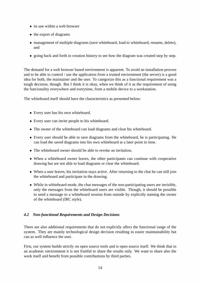
Fig. 8 sports ChatStorm’s architecture. It shows clearly that ChatStorm significantly differen-tiates from a standard CEWebS insofar as the synchronous connection between its users is nothandled by standard Web service calls but through separate XMLSockets. It has to be men-tioned that this can pose a problem when Web server A and B do not reside within the samedomain, since the SWF client can only connect to servers from the same domain it was deliveredfrom (though buying a certificate from Macromedia could solve this problem).
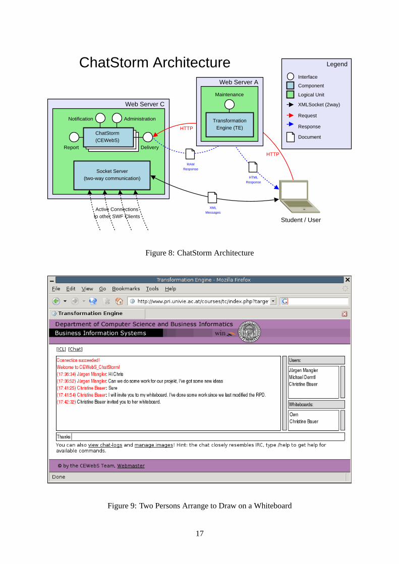
The system works basically as described in the in the preceding chapters. Fig.9 points out thesimplicity of the user interface (UI) in the chat mode:
The UI consists of only four parts:
• The main area where all the messages are printed,
• an input field for writing messages (which are delivered to the server when pressing theenter key),
• an areaUserswhere all users are listed, and
• an areaWhiteboardswhere all whiteboards, a user is authorised to access, are listed (ofcourse, theOwnwhiteboard is always listed).
16
Web Server C
Socket Server(two-way communication)
ChatStorm(CEWebS)
Report
Notification Administration
Delivery
Active Connectionsto other SWF Clients
HTTP
HTTP
HTMLResponse
RAWResponse
Student / User
ChatStorm Architecture
XMLMessages
Web Server A
TransformationEngine (TE)
Maintenance
Legend
Request
Response
Document
XMLSocket (2way)
Logical Unit
Interface
Component
Figure 8: ChatStorm Architecture
Figure 9: Two Persons Arrange to Draw on a Whiteboard
17
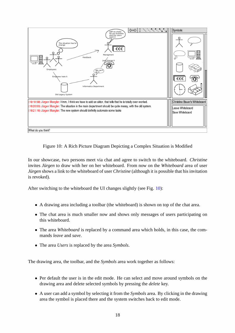
Figure 10: A Rich Picture Diagram Depicting a Complex Situation is Modified
In our showcase, two persons meet via chat and agree to switch to the whiteboard.ChristineinvitesJürgento draw with her on her whiteboard. From now on theWhiteboardarea of userJürgenshows a link to the whiteboard of userChristine(although it is possible that his invitationis revoked).
After switching to the whiteboard the UI changes slightly (see Fig.10):
• A drawing area including a toolbar (the whiteboard) is shown on top of the chat area.
• The chat area is much smaller now and shows only messages of users participating onthis whiteboard.
• The areaWhiteboardis replaced by a command area which holds, in this case, the com-mandsleaveandsave.
• The areaUsersis replaced by the areaSymbols.
The drawing area, the toolbar, and theSymbolsarea work together as follows:
• Per default the user is in the edit mode. He can select and move around symbols on thedrawing area and delete selected symbols by pressing thedeletekey.
• A user can add a symbol by selecting it from theSymbolsarea. By clicking in the drawingarea the symbol is placed there and the system switches back to edit mode.
18
• The toolbar provides undo / redo and holds also some basic functionalities like:
– writing text,
– connecting symbols with solid lines and dashed lines,
– connecting symbols with one-way arrows, and
– connecting symbols with two-way arrows.
6 Conclusions
When analysing our students’ cooperation for realising Rich Picture Diagrams, we noticed alack in an adequate tool.
Currently available web-based whiteboard tools support common drawing features - similarto MS-Paint - with additional video and voice conferencing possibilities, as well as the func-tionality of sharing documents or online presentations. However, in informatics, teams enjoythe advantage of formalised languages - e.g. the Unified Modelling Language (UML). Sincewhiteboards do not support any formalisation, they do not make this advantage effective.
Drawing onto the screen using the mouse appears to result in some non-formalised, bad-lookingscribbling that is hard to extend and which makes it hard to modify or delete fragments.
Our analysis revealed that informatics and computer science students make use of UML andNetwork Diagram symbols and methods even for creating Rich Picture Diagrams (RPDs),which do not demand any formalisation.
We developed a simple, extendable chat application that can be embedded into existing learningenvironments through a Web service framework and focuses on using a cooperative modellingapproach instead of cooperative drawing. With this tool, we want to enable the use of an (atleast) semi-formalised language, giving effect to its advantage in an online cooperation setting.
The prototype provides the implementation of autoshapes, which can be adapted in size andposition. The main benefits of our component include easy extensibility or replacement ofexisting solutions in an OS / platform-independent manner, and a focus on a formalised way ofexchanging ideas. This should result in a simplified user interaction and transparent recordingof brainstorming processes. Further research will include the identification of useful sets ofprimitives, not only for informatics and computer science students but also for students fromother domains.
In the pilot phase (summer term 2005), we want to evaluate if minimal additional functionalitieslike choosing different colours for symbols as well as enable rotation and flipping will enhancethis tool’s adequacy.
19

Figure 11: Which Use-Cases can occur in ChatStorm?
7 The Client
7.1 The Use-Cases
The client for chatting and drawing is a Rich Internet Application [21], which is programmedin Macromedia Flash. There exist three groups of functionalities (see Fig.11):
• Manage Diagramsis realised as common CEWebS command.
• Board Modus, Chat Modusand switching between them are are part of the Flash compo-nent.
• TheAdministration(realised through CEWebS Administration interface)
In the following the functionality is described in detail:
20
• The user enters his username and password in order to use ChatStorm.
• The user can chat online with other users, send them invitations for his board by clickingtheir names, and receive invitations from other users to their boards.
• The user can enter his own board or use an invitation to enter another board.
• For every participant of a board it is possible to drag symbols onto it, delete them, andconnect them.
• Every participant can save a board for his own usage (import to his own board, downloadit, ...)
• Every user can enlarge a board (drawing area).
• Every user can exit a board and return to the chat-only mode.
• Only a board’s owner can clear a board.
• Every user can manage the drawings he/she saved by himself/herself (there is no dif-ference between drawings one saved from his/her own board to those he/she saved fromanother user’s board). Managing drawings includes downloading PNG/SVG versions anddeleting saved drawings.
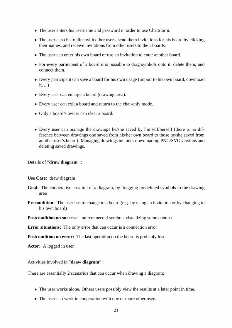
Details of ”draw diagram” :
Use Case:draw diagram
Goal: The cooperative creation of a diagram, by dragging predefined symbols to the drawingarea
Precondition: The user has to change to a board (e.g. by using an invitation or by changing tohis own board)
Postcondition on success:Interconnected symbols visualizing some context
Error situations: The only error that can occur is a connection error
Postcondition on error: The last operation on the board is probably lost
Actor: A logged in user
Activities involved in ”draw diagram” :
There are essentially 2 scenarios that can occur when drawing a diagram:
• The user works alone. Others users possibly view the results at a later point in time.
• The user can work in cooperation with one or more other users.
21
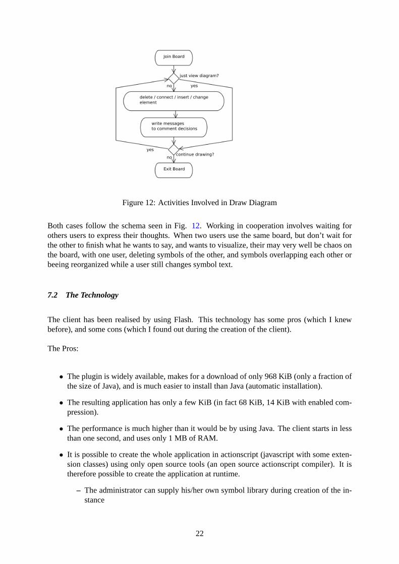
Figure 12: Activities Involved in Draw Diagram
Both cases follow the schema seen in Fig.12. Working in cooperation involves waiting forothers users to express their thoughts. When two users use the same board, but don’t wait forthe other to finish what he wants to say, and wants to visualize, their may very well be chaos onthe board, with one user, deleting symbols of the other, and symbols overlapping each other orbeeing reorganized while a user still changes symbol text.
7.2 The Technology
The client has been realised by using Flash. This technology has some pros (which I knewbefore), and some cons (which I found out during the creation of the client).
The Pros:
• The plugin is widely available, makes for a download of only 968 KiB (only a fraction ofthe size of Java), and is much easier to install than Java (automatic installation).
• The resulting application has only a few KiB (in fact 68 KiB, 14 KiB with enabled com-pression).
• The performance is much higher than it would be by using Java. The client starts in lessthan one second, and uses only 1 MB of RAM.
• It is possible to create the whole application in actionscript (javascript with some exten-sion classes) using only open source tools (an open source actionscript compiler). It istherefore possible to create the application at runtime.
– The administrator can supply his/her own symbol library during creation of the in-stance
22
– The library source is then compiled together with the rest of the flash componentinto the ready-to-use component (as part of the configuration of an instance)
• Flash supports the creation of drawing applications by functionality like layers, functionsto check if visible parts of images collide, fast rotation, scaling and drawing algorithms,...
The Cons:
• The open source compiler is so far not able to create files with own classes. So the designis object oriented but realised in a procedural manner.
• Only the commercial version of Macromedia Studio offers additional libraries that allowthe creation of user interfaces using predefined widgets. With the open source compilerone has to create one’s own widgets.
During the creation I also realised that it was sometimes difficult for me to understand howthings work in Flash. I think it is not so much a problem of the system, but more of a problemof world perspective. Everything works with layers, timelines and events, concepts that areobvious to artists/creatives i.e. persons that work with tools like Photoshop or movie editors.For an object focused person like myself it was not so easy to understand how things worktogether when I started the project.
7.3 Creating Symbol Libraries
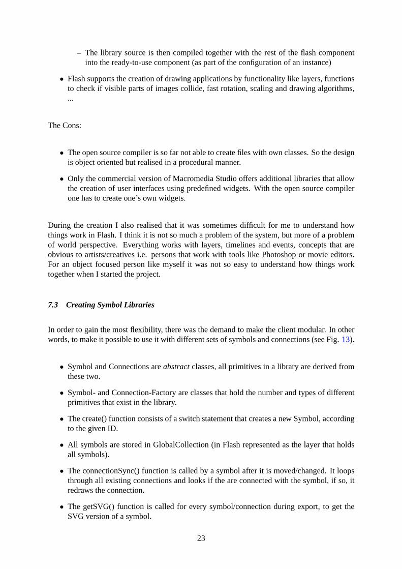
In order to gain the most flexibility, there was the demand to make the client modular. In otherwords, to make it possible to use it with different sets of symbols and connections (see Fig.13).
• Symbol and Connections areabstractclasses, all primitives in a library are derived fromthese two.
• Symbol- and Connection-Factory are classes that hold the number and types of differentprimitives that exist in the library.
• The create() function consists of a switch statement that creates a new Symbol, accordingto the given ID.
• All symbols are stored in GlobalCollection (in Flash represented as the layer that holdsall symbols).
• The connectionSync() function is called by a symbol after it is moved/changed. It loopsthrough all existing connections and looks if the are connected with the symbol, if so, itredraws the connection.
• The getSVG() function is called for every symbol/connection during export, to get theSVG version of a symbol.
23
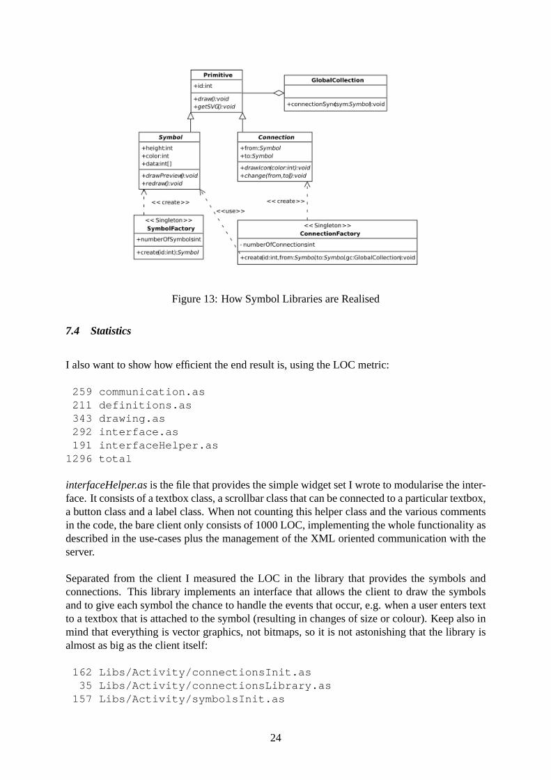
Figure 13: How Symbol Libraries are Realised
7.4 Statistics
I also want to show how efficient the end result is, using the LOC metric:
259 communication.as211 definitions.as343 drawing.as292 interface.as191 interfaceHelper.as
1296 total
interfaceHelper.asis the file that provides the simple widget set I wrote to modularise the inter-face. It consists of a textbox class, a scrollbar class that can be connected to a particular textbox,a button class and a label class. When not counting this helper class and the various commentsin the code, the bare client only consists of 1000 LOC, implementing the whole functionality asdescribed in the use-cases plus the management of the XML oriented communication with theserver.
Separated from the client I measured the LOC in the library that provides the symbols andconnections. This library implements an interface that allows the client to draw the symbolsand to give each symbol the chance to handle the events that occur, e.g. when a user enters textto a textbox that is attached to the symbol (resulting in changes of size or colour). Keep also inmind that everything is vector graphics, not bitmaps, so it is not astonishing that the library isalmost as big as the client itself:
162 Libs/Activity/connectionsInit.as35 Libs/Activity/connectionsLibrary.as
157 Libs/Activity/symbolsInit.as
24
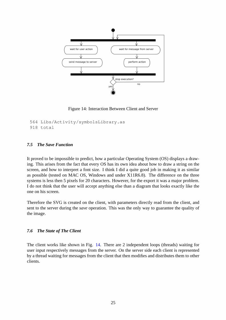
Figure 14: Interaction Between Client and Server
564 Libs/Activity/symbolsLibrary.as918 total
7.5 The Save Function
It proved to be impossible to predict, how a particular Operating System (OS) displays a draw-ing. This arises from the fact that every OS has its own idea about how to draw a string on thescreen, and how to interpret a font size. I think I did a quite good job in making it as similaras possible (tested on MAC OS, Windows and under X11R6.8). The difference on the threesystems is less then 5 pixels for 20 characters. However, for the export it was a major problem.I do not think that the user will accept anything else than a diagram that looks exactly like theone on his screen.
Therefore the SVG is created on the client, with parameters directly read from the client, andsent to the server during thesaveoperation. This was the only way to guarantee the quality ofthe image.
7.6 The State of The Client
The client works like shown in Fig.14. There are 2 independent loops (threads) waiting foruser input respectively messages from the server. On the server side each client is representedby a thread waiting for messages from the client that then modifies and distributes them to otherclients.
25
Figure 15: Class Diagram of the Server
8 The Server
Although the implementation can’t be fully described in UML because it uses more advancedfeatures like runtime overloading of classes and closures, Fig.15 should be a pretty goodrepresentation:
To understand the Class Diagram it’s necessary to have some additional information:
1. Kernel is the root object, this makesusers, boards, andsessionsglobal variables
• sessionsis a flat list of all sessions
• usersandboardsare indexed by CEWebS instance and CEWebS user id (matricula-tion number for students)
2. The HelperThread is a thread that runs every few seconds and cleans up these globalvariables (removes stale sessions and associated boards and information)
• It iterations overusersand checks if the counter equals 0, if so, it sends a messageto all sessions with the same instance, that the user has disconnected.
3. Server is basically a group that opens a new thread for every connection to the socketwhile
Thread.new(socket.accept) { |thisSession| }end
• socket.accept waits for connections, if a connection is initiated, the associated blockis started as new thread, and the session is handed over as parameterthisSession
26
• the concept of blocks (closures) is very easy to explain. A closure (see [32]) is ananonymous function (a function pointer) that lives in the lexical environment (see[31]) it has been created in. With this concept it is possible to spawn a newThreadvery easily by passing the code, plus the closure can access the variables of the scopeit has been created in (the variables inside the closure are private).
4. TCPSocketis an existing standard class, extended with some additional attributes.
• The concept of extending standard classes can not be fully expressed in UML. Theadvantage is, thatother existing classes, that rely on TCPSocket, are also extended.
5. each session has aUser
• for each session an entry fromuserscan be identified throughthisSession.instanceandthisSession.id
6. each session has aBoard
• for each session an entry fromboardscan be identified throughthisSession.instanceandthisSession.active
Inside a Thread (Server) the communication takes place:
while thisSessionfromClient = thisSession.gets(’’$\backslash$0’’)...
end
thisSessionwaits for XML chunks from the flash component, that are delimited by ”\0” charac-ters. These XML chunks are then validated and processed, according to their context (definedby #instance, #name, #active). These chunks are calledmessagesfrom now on.
To get the big picture, I measured again the LOC’s for the server.HelperThread, ServerandKernelare included in server.rb (they only exist in the diagram as separate classes to illustratethe concept). The numbers:
307 server.rb82 Includes/Board.rb19 Includes/TCPSocket.rb10 Includes/User.rb
418 total
The rest of this chapter is dedicated to the flow of themessages. The messages occur afterinput from the user in the flash component, and are sent to the server. The following diagramsvisualise the inner workings of the tool.
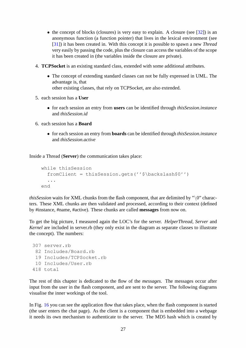
In Fig. 16you can see the application flow that takes place, when the flash component is started(the user enters the chat page). As the client is a component that is embedded into a webpageit needs its own mechanism to authenticate to the server. The MD5 hash which is created by
27
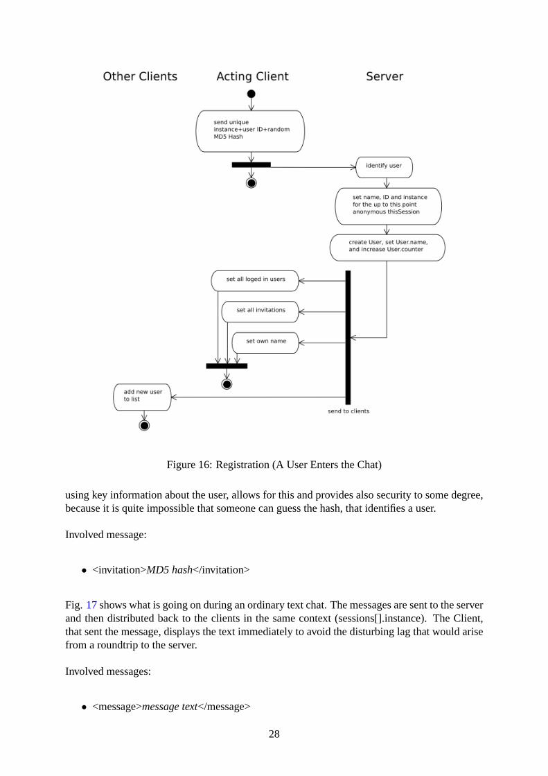
Figure 16: Registration (A User Enters the Chat)
using key information about the user, allows for this and provides also security to some degree,because it is quite impossible that someone can guess the hash, that identifies a user.
Involved message:
• <invitation>MD5 hash</invitation>
Fig. 17shows what is going on during an ordinary text chat. The messages are sent to the serverand then distributed back to the clients in the same context (sessions[].instance). The Client,that sent the message, displays the text immediately to avoid the disturbing lag that would arisefrom a roundtrip to the server.
Involved messages:
• <message>message text</message>
28
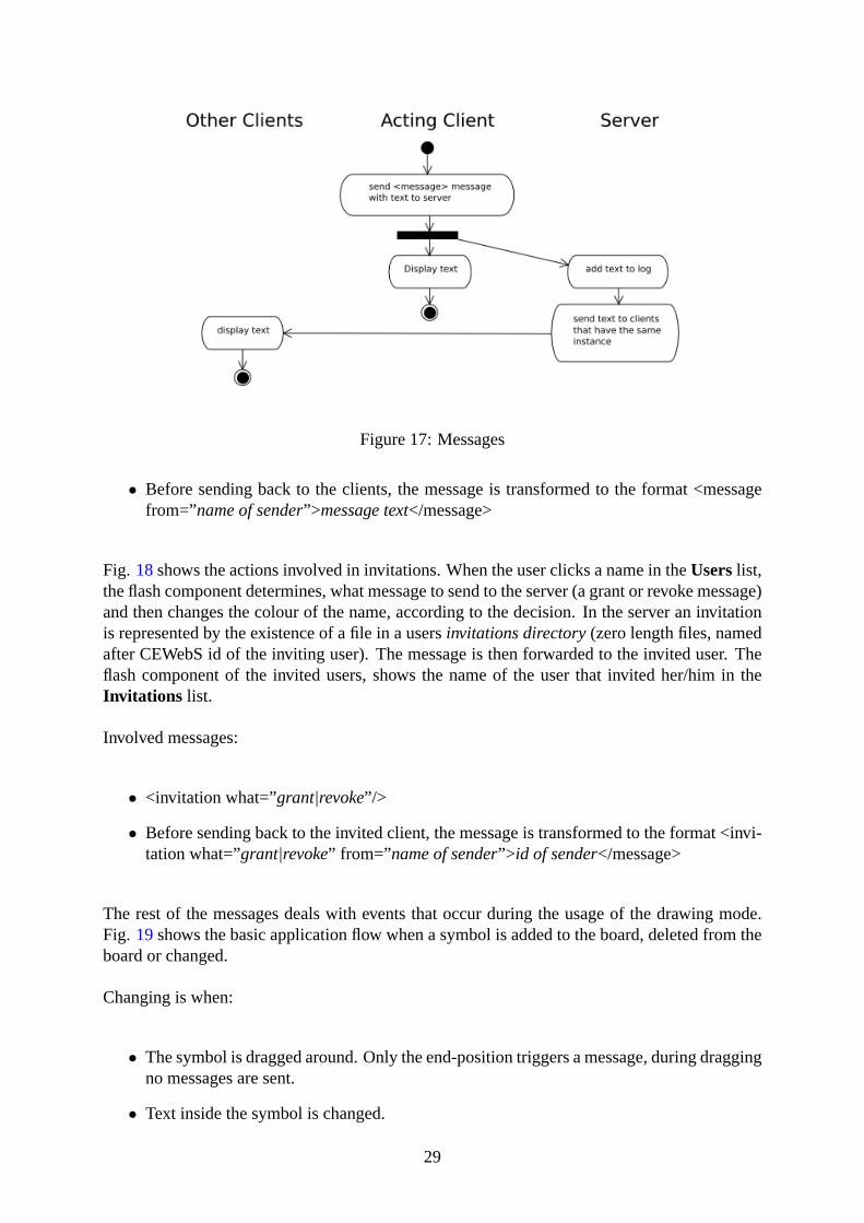
Figure 17: Messages
• Before sending back to the clients, the message is transformed to the format <messagefrom=”name of sender”>message text</message>
Fig. 18shows the actions involved in invitations. When the user clicks a name in theUserslist,the flash component determines, what message to send to the server (a grant or revoke message)and then changes the colour of the name, according to the decision. In the server an invitationis represented by the existence of a file in a usersinvitations directory(zero length files, namedafter CEWebS id of the inviting user). The message is then forwarded to the invited user. Theflash component of the invited users, shows the name of the user that invited her/him in theInvitations list.
Involved messages:
• <invitation what=”grant|revoke”/>
• Before sending back to the invited client, the message is transformed to the format <invi-tation what=”grant|revoke” from=” name of sender”> id of sender</message>
The rest of the messages deals with events that occur during the usage of the drawing mode.Fig. 19shows the basic application flow when a symbol is added to the board, deleted from theboard or changed.
Changing is when:
• The symbol is dragged around. Only the end-position triggers a message, during draggingno messages are sent.
• Text inside the symbol is changed.
29
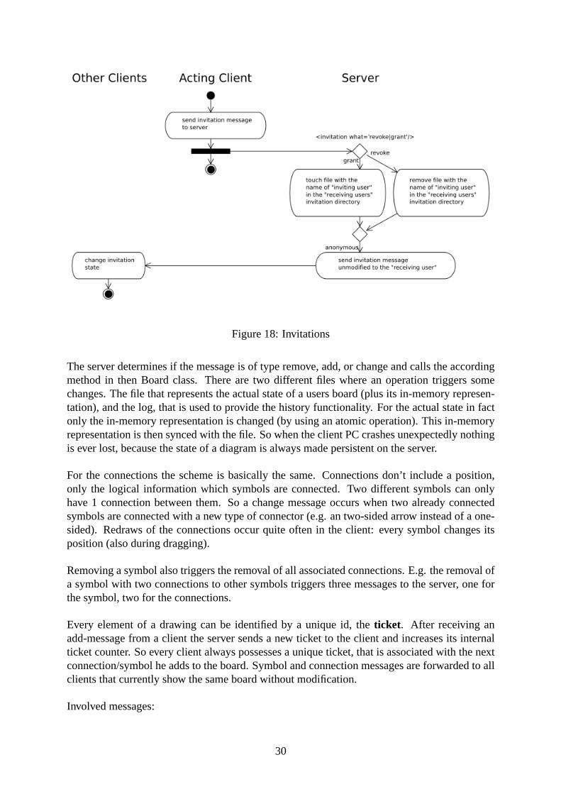
Figure 18: Invitations
The server determines if the message is of type remove, add, or change and calls the accordingmethod in then Board class. There are two different files where an operation triggers somechanges. The file that represents the actual state of a users board (plus its in-memory represen-tation), and the log, that is used to provide the history functionality. For the actual state in factonly the in-memory representation is changed (by using an atomic operation). This in-memoryrepresentation is then synced with the file. So when the client PC crashes unexpectedly nothingis ever lost, because the state of a diagram is always made persistent on the server.
For the connections the scheme is basically the same. Connections don’t include a position,only the logical information which symbols are connected. Two different symbols can onlyhave 1 connection between them. So a change message occurs when two already connectedsymbols are connected with a new type of connector (e.g. an two-sided arrow instead of a one-sided). Redraws of the connections occur quite often in the client: every symbol changes itsposition (also during dragging).
Removing a symbol also triggers the removal of all associated connections. E.g. the removal ofa symbol with two connections to other symbols triggers three messages to the server, one forthe symbol, two for the connections.
Every element of a drawing can be identified by a unique id, theticket. After receiving anadd-message from a client the server sends a new ticket to the client and increases its internalticket counter. So every client always possesses a unique ticket, that is associated with the nextconnection/symbol he adds to the board. Symbol and connection messages are forwarded to allclients that currently show the same board without modification.
Involved messages:
30
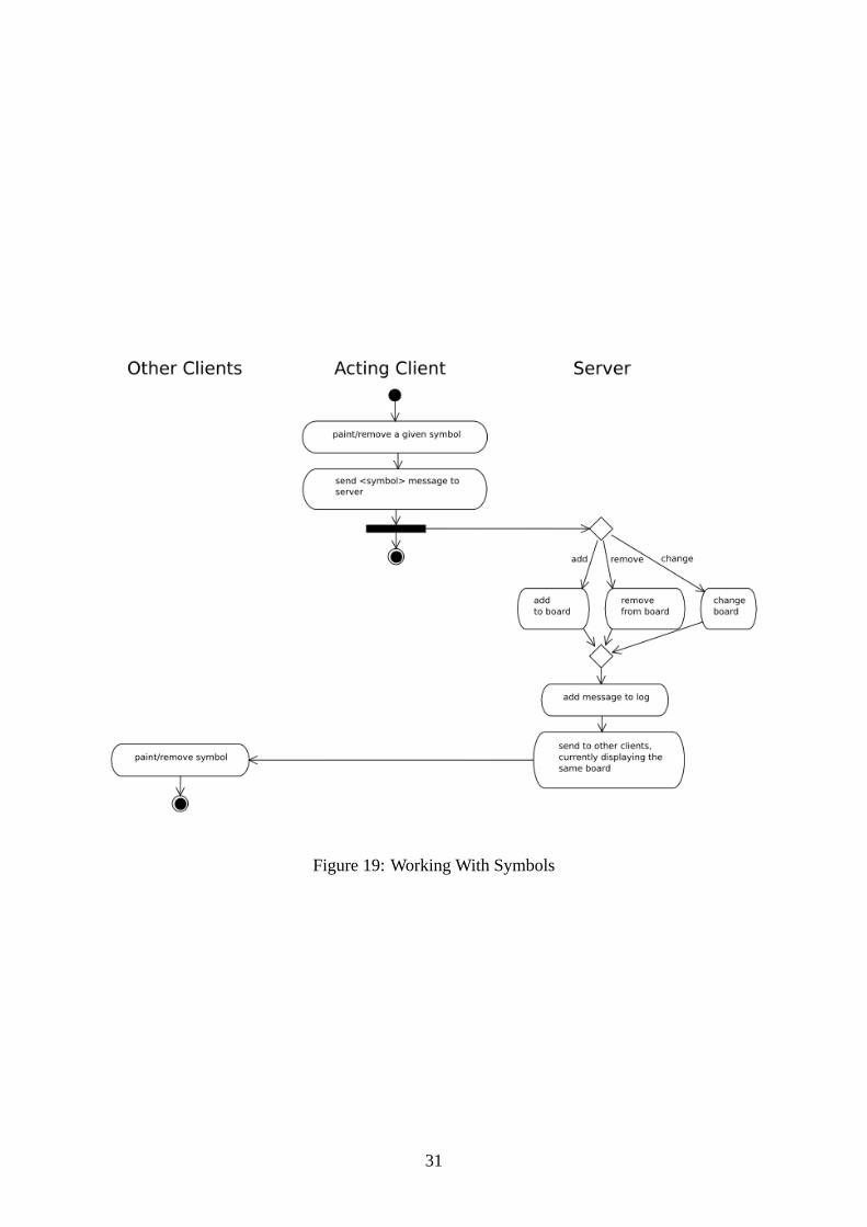
Figure 19: Working With Symbols
31
• <symbol what=”add|change|del” id=” id of the symbol” ticket=” ticket” x=” position” y=” position”/>
• Each symbol message, can have an arbitrary number of <data></data> elements, that holdadditional information like text that is associated with a symbol
• The id holds a numeric value that identifies the symbol in the current library
• The server knows nothing about the semantics of the symbol, only the correct library inclient can interpret it
• <connection what=”add|change|del” id=” id of the connection” ticket=” ticket” a=”symbolfrom” b=” symbol to”/>
• A connection has no associated <data></data> elements so far. To realise labelled arrowsI would prefer the label to be symbols without a position that is associated with the arrow.
In Fig. 20 you can see the involved steps in saving an image. Saving the image proved to bequite complicated, given the fact that different operating systems treat fonts differently. E.g. thesentence ”I am a cutie” has a different length according to the font rendering engines in Cocoa(Mac), X11 (Unix) or Windows, given the optimal situation that the font is available under allthree environments. The font metrics are vital to calculate the size of a symbol, so I decidedto create the SVG in the flash component, just to ensure that the result looks the same as onthe screen at least for the user that hits theSavebutton. Naturally the problem persists whensending the SVG to a user, who works on a different platform.
The SVG is sent to the server, where it is saved to a file. An actual state of the board is saved to aseparate file, for that it can be loaded later back into the board. The history information (provid-ing undo functionality) is lost for now (the functionality to preserve it should be implementedat some point in the future).
Involved Messages:
• <saveas width=”in pixel” height=”in pixel” name=”user input”>SVG representation ofthe drawing</saveas>
• the SVG representation is not a valid SVG file, only a flat list of all elements, it istransformed in a valid document on the server side
The last three diagrams are rather trivial UseCases. Join (see Fig.21) basically drops allsymbols from the (invisible) boards, gets the actual state of the board from the server, builds thedrawing, and then scrolls the board open.
Involved messages:
• <join>id of user representing an invitation orown</join>
32
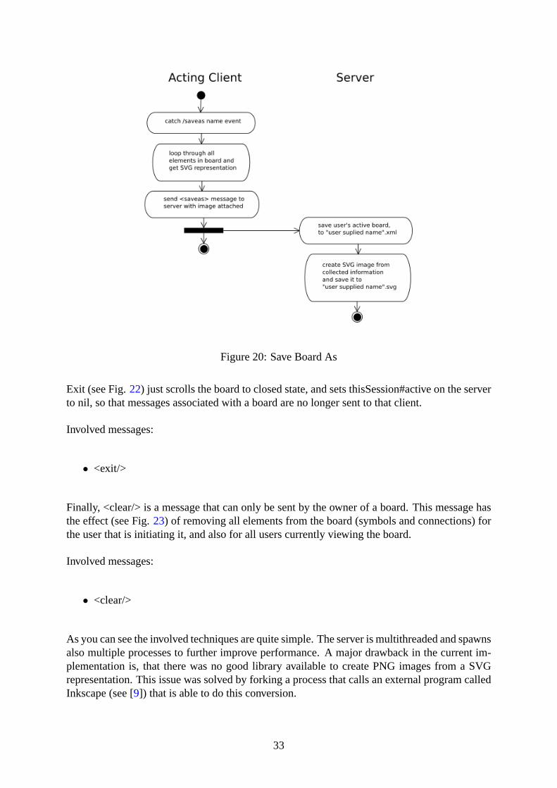
Figure 20: Save Board As
Exit (see Fig.22) just scrolls the board to closed state, and sets thisSession#active on the serverto nil, so that messages associated with a board are no longer sent to that client.
Involved messages:
• <exit/>
Finally, <clear/> is a message that can only be sent by the owner of a board. This message hasthe effect (see Fig.23) of removing all elements from the board (symbols and connections) forthe user that is initiating it, and also for all users currently viewing the board.
Involved messages:
• <clear/>
As you can see the involved techniques are quite simple. The server is multithreaded and spawnsalso multiple processes to further improve performance. A major drawback in the current im-plementation is, that there was no good library available to create PNG images from a SVGrepresentation. This issue was solved by forking a process that calls an external program calledInkscape (see [9]) that is able to do this conversion.
33

Figure 21: Join Board
34

Figure 22: Exit Board
Figure 23: Clear Board
35
9 The Interaction With CEWebS
The CEWebS is a Web service that delivers XML data to the Transformation Engine (TE). TheTE transforms the XML data to a format that is suitable for a particular client (HTML, WML)respective translates commands from the client to the format that is demanded by the CEWebS.The communication between all involved parts (CEWebS, TE, client) uses http. But our chat /drawing solution demands for asynchronous communication, so we created a flash component,that is able to communicate with a server via XML sockets.
The flash component is embedded in the XML data which the CEWebS delivers, and submittedto the client in form of an object (embedded in the HTML code).
Because a CEWebS can not provide asynchronous communication, it was necessary to build theseparated GraphTalk server, that shares data with the CEWebS. Because the flash component isindependent from the CEWebS, it needs its own authentication mechanism. Authentication isprovided in form of key, that is attached to the object.
The key is a unique MD5 hash (created with an random number) that is associated with auser/instance combination. This key is attached to the HTML-embedded object. When theuser enters the page, the flash component is initialised, the key is sent to the GraphTalk server,which extracts the user information (instance, user, name) from the shared data source. Theinformation is then delivered back to the client (in fact to all other clients in the same instance)(see Fig.24).
After this initialisation, the socket is associated with the user, and the GraphTalk server hasaccess to the shared data repository that holds the board of the user and also the saved drawings.
Every message leads to an immediate synchronisation with the CEWebS accessible XML data.No other interaction is necessary.
10 A Library for Creating BLESS Models
To support the Knowledge Experts workgroup (see [12]) in their efforts to create graphicalmodels of courses, we created a symbol library based on the BLESS [19] model. The Blessmodel uses coloured elements of activity diagrams [6, p 22] to visualise the flow of a course.
Because modelling these courses is a cooperative effort by definition, GraphTalk is very wellsuited:
• The board is projected to a wall with a beamer, graphs can be created and modified co-operatively during a meeting, a user can show his idea to the others by modifying theboard.
• Members can model a course together, while they are at different locations
36

Figure 24: The Interaction While Displaying The Component
37
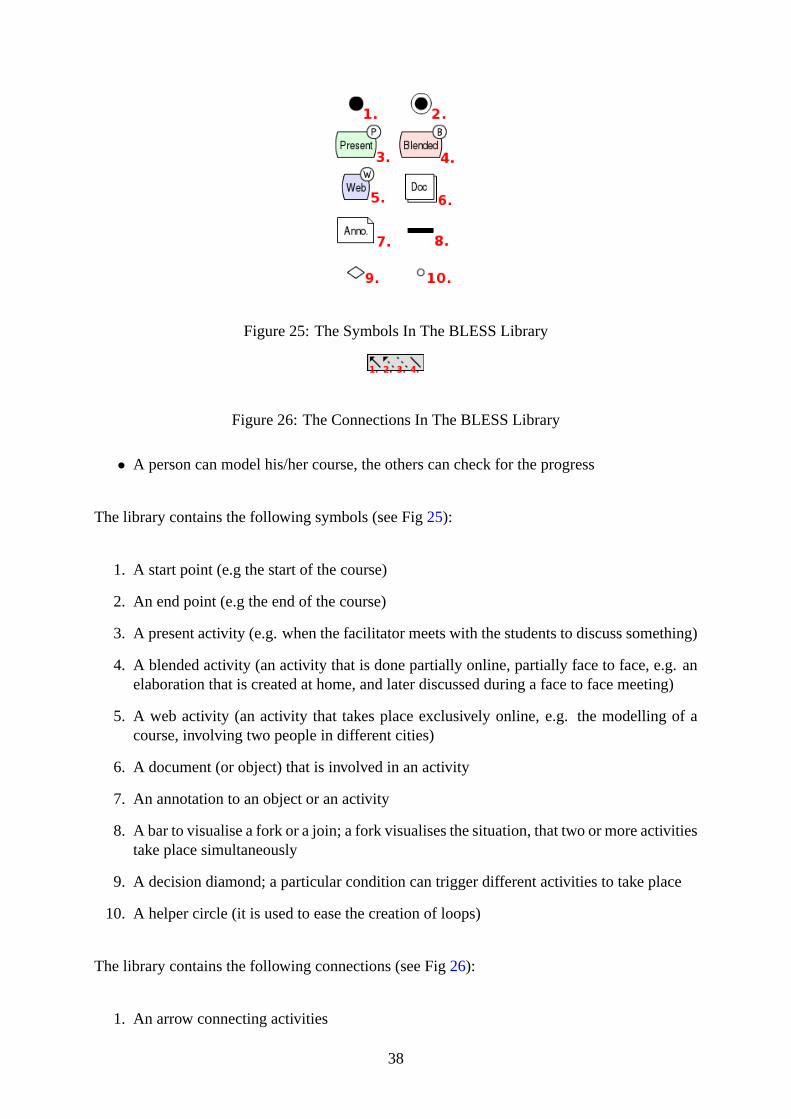
Figure 25: The Symbols In The BLESS Library
Figure 26: The Connections In The BLESS Library
• A person can model his/her course, the others can check for the progress
The library contains the following symbols (see Fig25):
1. A start point (e.g the start of the course)
2. An end point (e.g the end of the course)
3. A present activity (e.g. when the facilitator meets with the students to discuss something)
4. A blended activity (an activity that is done partially online, partially face to face, e.g. anelaboration that is created at home, and later discussed during a face to face meeting)
5. A web activity (an activity that takes place exclusively online, e.g. the modelling of acourse, involving two people in different cities)
6. A document (or object) that is involved in an activity
7. An annotation to an object or an activity
8. A bar to visualise a fork or a join; a fork visualises the situation, that two or more activitiestake place simultaneously
9. A decision diamond; a particular condition can trigger different activities to take place
10. A helper circle (it is used to ease the creation of loops)
The library contains the following connections (see Fig26):
1. An arrow connecting activities
38

Figure 27: Project Management, Soft Skills
2. An arrow connecting documents (objects) and activities
3. A line connecting documents and activities with annotations
4. A helper line to allow for the creation of loops
First tests with users showed that they indeed like the simplicity our modelling componentprovides, as well as the narrow focus on a particular problem and the interactive possibilities.You can see a model that uses all symbols to describe our course ”Project Management, SoftSkills” in Fig 27 (modelled by Christoph Wichtl and Michael Derntl).
11 Thanks And Additional Information
Thanks go toChristine Bauer, for being patient, helpful, and empathic. The discussions withher and her work made it possible to submit a great paper to the ICL conference. Thank youalso for proof-reading large parts of the work.
39

Helmut Waneksupported me with his hardcore proof-reading abilities and his comments andinput have affected this paper to a great degree.
Last but not least, thanks go toRenate Motschnig, Michael DerntlandChristoph Wichtl, forsupporting me with their UML and modelling knowledge, and for being helpful and patient.
To access this document and its revision history visitour WIKI. The document has been createdby using Scientiki, a CEWebS component. The graphics in this document were created by usingThe Gimp, Inkscape, Dia, andPoseidon Community Edition. The PDF document has been setusing LaTeX 2e. All tools involved arefreeor opensoftware.
40
References:
[1] Adams, Lia, Toomey, Lori and Churchill, Elizabeth: ”Distributed Research Teams: Meet-ing Asynchronously in Virtual Space”; Journal of Computer-Mediated Communication, 4(4),1999, available athttp://www.ascusc.org/jcmc/vol4/issue4/adams.html[last access De-cember 19, 2001].
[2] Adusumilli, Krishna K., Al-Halabi, Bassem and Hsu, Sam: ” SOFTBOARD - A Web-based Application Sharing System for Distance Education”, IEEE International Conferenceon Information Technology: Coding and Computing (ITCC 2000), March 27-29, 2000, LasVegas, Nevada, pp. 338-341.
[3] Boos, Margarete: ”Computergestützte Problemstrukturierung in Arbeitsgruppen”, in:Boos, Margarete, Jonas, Kai J. and Sassenberg, Kai (eds.): ”Computer-vermittelte Kommu-nikation in Organisationen”. Göttingen: Hogrefe, Verlag für Psychologie, 2000, pp. 73-87.
[4] Brill, Andreas and de Vries, Michael: ”Cybertalk: Die Qualitätender Kommunikation im Internet”, 1997, available athttp://www.uni-wh.de/de/wiwi/virtwirt/konf/cybertal/cybtalk.pdf[last access December 18, 2001].
[5] Checkland, P., Scholes, J.: ”Soft Systems Methodology in Action”, Wiley, Chichester,1990.
[6] Eriksson, Hans-Erik and Penker, Magnus: ”UML Toolkit”, John Wiley and Sons, Inc, 1998.
[7] User Data Connections Limited, ”Groupboard - Interactive website tools for educa-tion, business and fun”, information available viahttp://www.groupboard.com/[last accessSeptember 17, 2004].
[8] Hollingshead, Andrea B. and McGrath, Joseph E.: ”Computer-assisted groups: a criticalreview of the empirical research”, in: Guzzo, Richard A. and Salas, Eduardo (eds.): ”Teameffectiveness and decision making in organizations”. San Francisco: Jossey-Bass, 1995, pp.46-78.
[9] Inkscape: ”Inkscape: Open Source Scalable Vector Graphics Editor”, available athttp://www.inkscape.org[last access January 11, 2005].
[10] IRC: ”Internet Relay Chat”, available athttp://en.wikipedia.org/wiki/Internet_Relay_Chat[last access August 29, 2004].
[11] Ishaya, Tanko and Macaulay, Linda: ”The Role of Trust in Virtual Teams”, Elec-tronic Journal of Organizational Virtualness, 1 (1), 1999, pp. 140-157, available athttp://www.virtual-organization.net/files/articles/Ishaya_US.pdf[last access October 17,2001].
[12] Knowledge Experts,http://leonardo.pri.univie.ac.at/communities/kex, [last access January16, 2005]
[13] Macromedia Flash: ”Macromedia Flash”, Macromedia Corporation, information and plu-gins available athttp://www.macromedia.com/software/flash/[last access June 15, 2004].
41
[14] Mangler, Jürgen and Derntl, Michael: ”CEWebS - Cooperative Environment Web Ser-vices”, Proceedings of I-Know 2004, Graz.
[15] McCue, G.M.: ”IBM’s Santa Teresa Laboratory - architectural design for program devel-opment”, IBM Systems J., 17 (1), pp. 4-25, 1978.
[16] NetMeeting: ”MS NetMeeting”, Microsoft Corporation, information available athttp://www.microsoft.com/windows/netmeeting/features/whiteboard/default.asp[last accessJune 15, 2004].
[17] Ming: ”Ming - a SWF output library and PHP module”, available online viahttp://www.sourceforge.net[last access July 5, 2004].
[18] Motschnig, Renate and Derntl, Michael: ”Can the Web Improve the Effectiveness ofPerson-Centered Learning? Case Study on Teaching and Living Web-Engineering”, Pro-ceeding s of the IADIS International Conference WWW/Internet, Algarve, Portugal, 2003.
[19] Motschnig, Renate and Derntl, Michael: ”BLESS - A Layered Blended Learning SystemsStructure”, Proceedings of I-Know 2004, Graz.
[20] OMG: ”OMG Unified Modeling Language Specification, Version 1.5, March 2003”, avail-able athttp://www.omg.org/cgi-bin/doc?formal/03-03-01[last access May 12, 2003].
[21] Grant D. Skinner:Creating usable interfaces for online applications. SIGGRAPH WebGraphics 2003
[22] Ruby: ”Ruby”, from Yukihiro Matsumoto and Others, available athttp://www.ruby-lang.org[last access July 6, 2004].
[23] IBM Cooperation, ”IBM Rational Unified Process”, information available viahttp://www-306.ibm.com/software/awdtools/rup/[last access September 17, 2004].
[24] Schwabe, Gerhard: ”’Mediensynchronizität’ - Theorie und Anwendung bei Gruppenarbeitund Lernen”, in: Friedrich, Herlmut F. and Hesse, Friedrich W. (eds.): ”Partizipation undInteraktion im virtuellen Seminar”; Waxmann Verlag, Münster, 2001.
[25] Vitgen, R.: ”Developing Web Information Systems”, Butterworth-Heinemann, 2002.
[26] Walther, Joseph B.: ”Interpersonal Effects in Computer-Mediated Interaction: A Rela-tional Perspective”, Communication Research, 19 (1), 1992, pp. 52-90.
[27] Walther, Joseph B.: ”Relational Aspects of Computer-mediated Communication: Experi-mental Observations over Time”, Organization Science, 6 (2), 1995, pp. 186-203.
[28] Walther, Joseph B.: ”Computer-Mediated Communication: Impersonal, Inter-personaland Hyperpersonal Interaction”, Human Communication Research, 23 (1), 1996, pp 3-43.
[29] Watzlawick, Paul, Beavin, Janet H. and Jackson, Don D., ”Menschliche Kommunikation:Formen, Störungen, Paradoxien”, 10th unchanged edition. Bern: Huber, 2000.
[30] WebCT, ”WebCT”, WebCT Incorporated, http://www.webct.com/ [lastaccess September 17, 2004], WebCT whiteboard basics available fromhttp://www.its2.uidaho.edu/help_docs/webct_whiteboard/2_whiteboard_basics.htm[lastaccess September 17, 2004].
42

[31] Wikipedia, ”Lexial Environment”, http://en.wikipedia.org/wiki/Lexical_environment,[last access January 9, 2005]
[32] Wikipedia, ”Closures”,http://en.wikipedia.org/wiki/Closure_%28computer_science%29,[last access January 9, 2005]
Authors:
Jürgen ManglerUniversity of ViennaDepartment of Computer Science and Business InformaticsRathausstraße 19/91010 Vienna, [email protected]
Christine BauerPhD. StudentUniversity of ViennaDepartment of Computer Science and Business InformaticsRathausstraße 19/91010 Vienna, [email protected]
Origin:
Christine Bauer an myself submitted the first part of this work (chapters 1 to 6) to the ICL 2004in Villach. The paper was accepted and we had a poster presentation. So the first part is a realcooperation, with changes and input in every chapter from both of us. When forced to tell whatchapters are more from Christine, I would saychapter 3, which she originally wrote alone. Atleast the draft for all all other chapters stems from me.
Chapters7 to 10are my original work of which I am the single author.
43