Embed Size (px)
Citation preview

A Case Study for Waterproofing Below Grade Walls Shored with Continuous Soil Mix Technology Using a Bentonite Waterproofing System
Amanda Prot Rodney Lock Stéphane Hoffman

Outline
• Project Requirements • Site History and Location • Selection of Excavation and Shoring • CSM Shoring Technology • Selection of Waterproofing • Installation and Field Conditions • Troubleshooting

Initial Project Requirements
• Seven story office building with four stories of underground parking
• Located south of downtown Seattle near waterfront
• Project site with sensitive soil and high water table
• Maximum below grade depth of 45 ft.
• Average excavation depth of 36 ft below water table
• Need to minimize risks associated with soil conditions both during construction and over long term

Site History & Conditions
• Historic waterfront location south of downtown Seattle
• Reclaimed from Elliott Bay during re-grading at turn of century
• Infill contained significant construction debris
• Currently less than ½ mile from Elliott Bay
• High water table & tidal fluctuations of ground water
• Methane and Petroleum contamination Approximate location of site

Site History & Conditions
• Adjacent historical buildings, structures, roads and utilities
• Sensitive to soil movement and settlement
• Adjacent historical building foundation required partial removal and replacement
• New micro piles to extend below current timber piles.

Excavation and Shoring Selection
• Significant dewatering of site required to excavate wood debris in fill.
• Dewatering of site for a drained shoring wall not practical and would drain surrounding settlement sensitive soils.
• Shoring needed to provide temporary lateral support to adjacent fill.
• Use of a shoring wall as a water tight cut off wall for dewatering of only the soils within the site required.
• Shoring to extend 25 ft below excavation depth to limit risk of seepage and base heave from deep aquifer.

Excavation and Shoring Selection
• Typical soldier piles and lagging • Not practical for this project due to soft and
wet nature fill and marine deposits. • Does not cut off ground water flow into site. • Not as stiff as other shoring – risk of
settlement of adjacent soils.
• Steel Sheet Piles • Not selected due to the depth of the
excavation. • Risk of interference and blockage of sheets
by existing fill debris.
• Secant Piles • Cost & schedule.

Excavation and Shoring Selection
• Cutter Soil Mixing Technology (CSM)
• Developed in Germany • Uses cutter wheels to mix
cement and bentonite clay slurry with soil in situ
• Overlapping soil-cement panels • Resulting in solid and mostly
water tight cut off wall • Steel solider piles driven into
the wet soil mix for strength

CSM Shoring Walls
• D • F

CSM Shoring Walls Benefits
• Minimal Vibration • Low noise • Ideal for shoring in granular,
contaminated and wet soils • Drilling chews through any
obstructions allowing for continuous vertical plane
• Can adjust strength of soil wall to project conditions

Anchoring
• Tie back anchors into CSM installed as excavation progressed
• Sleeves for tie back anchors provided in the steel solider piles
• Horizontal steel whalers used where obstructions prevented tie back installation

Selection of Waterproofing
• Evaluated a variety of waterproofing systems based on project requirements • Use of CSM shoring wall • Desire to use Shotcrete applied structural foundation walls • Hydrostatic conditions • Possibility of Methane and Petroleum contamination • Proximity to Puget Sound - tidal fluctuations – salinity of water
• Considered approach of using a sheet membrane in combination with integral waterproofing concrete admixture • Found to be economically unfeasible • Owners accepted higher risk of water infiltration as a result of
single system approach

Bentonite Waterproofing Membrane
• Selected approached used a dual layer of bentonite • First layer mechanically attached to CSM
• Minimum 4 inch laps for continuous membrane • Second layer attached similarly
• All laps sealed with bentonite mastic • Samples of soil and ground water tested by the
manufacturer for acceptable levels of salt and contaminants
• Use of HDPE liner on one layer of membrane limited leakage of methane into garage
Construction Considerations
• CSM Shoring Walls • Wavy CSM walls were
acceptable • Bentonite membrane needed
to be tightly secured against all variations in CSM
• Large voids or protrusions in CSM needed to be smoothed

CSM Shoring Walls as Bentonite Substrate

Water Through CSM Wall
• Water seapage through the CSM walls at joints and tie backs
• Installed a gutter system to capture as much water as possible and keep it out of the site

Water Through CSM
• Water on slabs typical throughout waterproofing and shotcrete installation
• Drying and prepartion of concrete joints required for waterstop
• Waterstop typically installed starting in early morning on day of shotcrete
• No time for water to build up and pre-hydrate bentonite

Water through the CSM
• Water seapage through CSM built up behind bentonite membrane
• Water would resist shotcrete pressure from pushing membrane against CSM
• Drainage slots cut into membrane 12 inch from slab levels
• Drainage slots vacuumed dry and then patched each morning prior to section of shotcrete
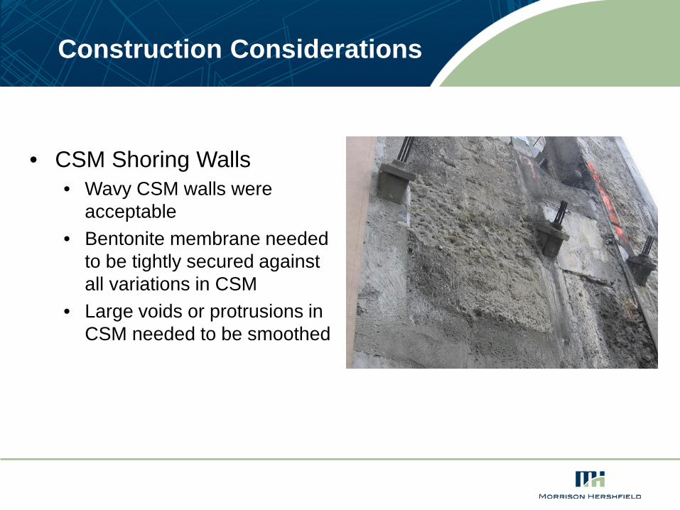
De-stressing and sealing tie backs

Troubleshooting
• Upon completion of construction, significant amount of water was noted seeping through cracks in concrete walls
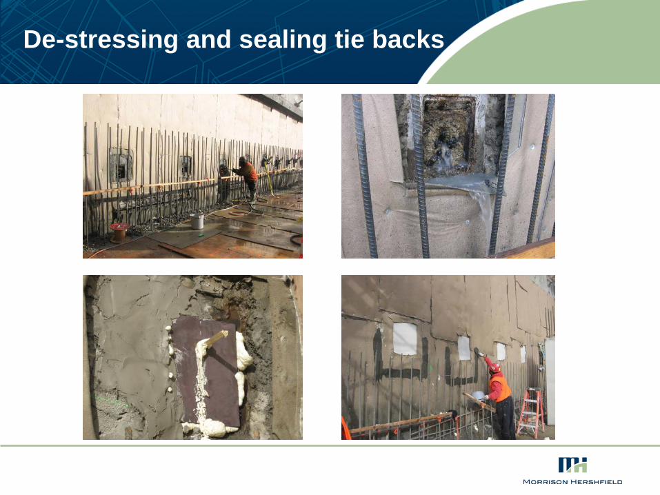
Troubleshooting
• Completed sample cores to review condition of shotcrete walls and bentonite membrane
• Revealed localized areas where foundation had separated from CSM shoring compromising confinement of bentonite

Troubleshooting
• Cause of the differential movement could not be conclusively established
• Post stressing of the below grade slabs were thought to be a likely contributor
• Bentonite grouting successfully used to fill voids and restore integrity of waterproofing
Conclusions
• CSM shoring wall successfully addressed the many challenges of excavating this site
• CSM provided a suitable surface for application of waterproofing with minimal parging
• Overall the CSM shoring wall performed well at minimizing water intrusion within the excavation
• Water intrusion at tie backs required special considerations during installation of waterproofing
• Consider the impact of post-stressing below grade slabs on the performance of the waterproofing
• Bentonite grouting successfully used to fill gaps and restore integrity of waterproofing

Thank You