Embed Size (px)
Citation preview

A Brief Tutorial on Power Management in Computer Systems
David Chalupsky, Emily Qi,
& Ilango Ganga Intel Corporation
March 13, 2007

March 11, 2007 File: chalupsky_01_03072
Objective & Agenda
Objective:• Establish a common foundation for EEESG work by providing
an overview and history of PC power management and LAN use in that context.
Agenda:
• High Level overview of PC power management– Links to additional information
• How Ethernet is utilized in Contemporary PC Power Management
• Making Power Management and Ethernet more effective in the future
March 11, 2007 File: chalupsky_01_03073
PC Power States circa 1990
• ON• OFF
Sounds nice & simple. What’s wrong with that?
• Time to boot the PC from a cold start took too long, and got longer as PCs became more complex.
• As a result, people left their PCs on all the time, wasting energy.

March 11, 2007 File: chalupsky_01_03074
Historical (1990’s) Motivation for Power Managementby market segment
Laptops & Battery Powered Devices– Battery Life is a key product feature, thus– Commercial incentive has always been there– Vendor-specific solutions preceded standards
Desktop PCs– Little end user benefit perceived for PM. – Initial attention to PM in 1992 with the release of EPA’s
Energy Star program and international counterparts.
Server Systems– Historically, a very performance oriented segment– Always on & ready for maximum performance– Recent, market-driven, attention to power due to high cost of
electricity & cooling in Data Centers– EPA just beginning to focus on Servers in 2006/2007

March 11, 2007 File: chalupsky_01_03075
Enter the Sleep State – 1990’s
To reduce PC energy consumption during periods of inactivity, the industry introduced the concept sleep, or standby, states.
Goals
• Power consumption at near Off levels
• Quick recovery to active state
Waking the System
• Return to active state based upon user input
• Keyboard, Mouse, Power Button
March 11, 2007 File: chalupsky_01_03076
Enter Wake On LAN
In corporate environments, PCs were STILL being left on all night.
• Systems backups, remote management and upgrades performed at night, over the LAN.
• IT needed system availability.
• Wake On LAN (WOL) allowed system to sleep at night and be turned on remotely for management.
• First products appeared ~1996.

March 11, 2007 File: chalupsky_01_03077
Power Management Standards
For multi-vendor interoperability, standards were required
• Initial effort: APM – Advanced Power Management– Early-mid 1990’s
• Current: ACPI – Advanced Configuration and Power Interface– 1996 – present– ACPI is still evolving to comprehend new system capabilities– Coordinated with supporting interface specifications:
• PCI Power Management, USB, Cardbus, PCI Express, etc.– Coordinated with supporting Device Class specifications:
• Network, Storage, Graphics, etc.
March 11, 2007 File: chalupsky_01_03078
Advanced Power Management (APM)The Legacy Method
• BIOS-based system power management– Operating System has no knowledge of what APM does
• Provides CPU and device power management
• Invoked when idle - provides CPU power mgt.
• Uses device activity timeouts to determine when to transition devices into low power states
• Each system board vendor must refine and maintain APM BIOS code/IP
• Wide variety of implementations and functionality – No uniform user experience
• Primitive Wake On LAN support
March 11, 2007 File: chalupsky_01_03079
ACPIAdvanced Configuration and Power Interface
An “interface” specification
Allows OS-directed Power Management (OSPM)
• ACPI/OSPM replaces APM, MPS, and PnP BIOS Spec
• PM awareness is global in the system, not hidden like in APM.
Defines
• Hardware registers - implemented in chipset silicon
• BIOS interfaces– Configuration tables– Interpreted executable function interface (Control Methods)– Motherboard device enumeration and configuration
• System and device power states
• ACPI Thermal Model
• Still evolving with system capability
March 11, 2007 File: chalupsky_01_030710
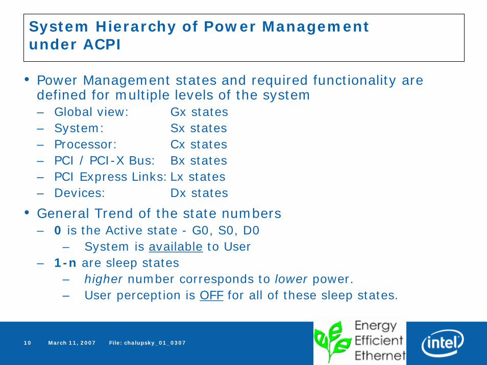
System Hierarchy of Power Managementunder ACPI
• Power Management states and required functionality are defined for multiple levels of the system– Global view: Gx states– System: Sx states– Processor: Cx states– PCI / PCI-X Bus: Bx states– PCI Express Links:Lx states– Devices: Dx states
• General Trend of the state numbers– 0 is the Active state - G0, S0, D0
– System is available to User– 1-n are sleep states
– higher number corresponds to lower power.– User perception is OFF for all of these sleep states.
March 11, 2007 File: chalupsky_01_030711
In the Interest of Time…
• More detailed descriptions of these power states are in the Backup section for the interested student.

March 11, 2007 File: chalupsky_01_030712
Hardware Ingredients Required for Wake On LAN
• PCI Power Management Provides– An Auxiliary Power Supply –
– 3.3VAux power available during Sleep when main power is off
– Mechanism for Signaling Wake Event to System– PME# or Wake# Signal
– Control & Status Registers– Device D-State Definition
• Network Device Class Specification Provides– Definition of Wake Up Packet Types and filters– Required behavior in the different power states.

March 11, 2007 File: chalupsky_01_030713
Example Transition from Working To Sleep State with Wake On LAN
State G, S, D States Action Power
Active G0, S0, D0 Normal Functionality Main=OnAux=on
Prepare for Sleep
G0, S0, D0->D3
OS loads wake up packet filter into LAN controller via Driver, sets Device Power State D3
Main=OnAux=on
Transition to Sleep
D3, S0-> S3 or S4G0-> G1
OS saves system state (memory image) to RAM or Disk.Main power off.
Main->offAux=on
Wake Event D3-> D0
S3/4-> S0G1-> G0
Wake packet received. Device asserts PME# or Wake#
Main=On
Aux=on

March 11, 2007 File: chalupsky_01_030714
Contemporary Use of LAN in Power Management
Though not standards-driven, these are common features provided by multiple vendors.
Disable LAN while System Active – Powering down the device when there’s no need to maintain the network connection. OS may place the device in D3 if no link indicated, setting a “wake on link status change” wake filter. Vendor-specific HW disable mechanisms for more “permanent” disable (BIOS setup).
Use Lower Speed for Wake on LAN – Upon transition to D3 state, if Gbit link currently established, Restart AutoNeg with only 10M or 10/100 advertised.
Low Speed for Battery – When laptop running on battery power, favor lower speed, i.e. Lowest Common Denominator, with Link Partner.
Smart Power Down / Energy Detect – When no receive signal detected, MAC/PHY mostly shut off except for receive energy detect circuit. Power is reduced significantly. From time to time link setup is attempted to avoid a deadlock condition where both Link partners support this feature.
Deep Smart Power Down – Similar to smart power down mode, but power supplies are also shut down.

March 11, 2007 File: chalupsky_01_030715
The Common Attribute of Contemporary Mechanisms
High Latency
Time required for link speed change or device enable/disable is very high.
Thus link manipulation for power savings is only used when the latency doesn’t matter
– Transition to Sleep
– LAN Disable
– Cable Disconnect
The Rapid PHY Selection feature of Energy Efficient Ethernet will provide the tools for Active State Power Management of the LAN Link

March 11, 2007 File: chalupsky_01_030716
Active State Power Management
PCI Express introduces Active State Power Management (ASPM)– For PCIe Links
Previous mechanisms focused on Sleep States (G1/S3-4/D3).
ASPM allows for power optimization when the system is still active and functional (G0/S0/D0 states)
PCIe Devices / Links can
• Go to electrical Idle autonomously, without software control (L0s)
• Renegotiate Link Width Quickly– Dropping from x8 to x1 can save 100mW+ per lane.
• Renegotiate Link Speed quickly– Move between Gen1 & Gen2 (2.5G & 5.0G) rates

March 11, 2007 File: chalupsky_01_030717
Summary
Power Management in Computer Systems continues to evolve
Sleep State definition has been the focus– RPS will provide greater functionality, faster transitions in & out of Sleep,
enabling wider adoption of power-friendly behaviors as computers are adapted to new applications.
Active State Power Management is a newer field.– Low latency transition capability between power/performance levels is key.
Customers, Manufacturers, and Regulatory agencies are focused onPower Efficiency, particularly in system Idle conditions.
Energy Efficient Ethernet will provide a necessary toolkit.
It WILL be used.
March 11, 2007 File: chalupsky_01_030718
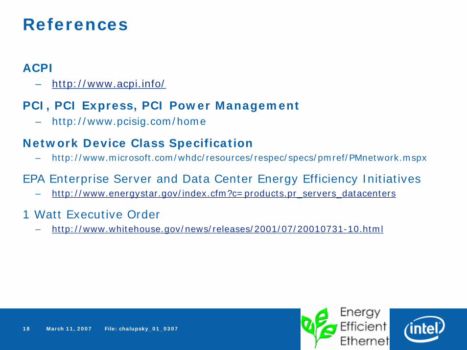
References
ACPI– http://www.acpi.info/
PCI, PCI Express, PCI Power Management– http://www.pcisig.com/home
Network Device Class Specification– http://www.microsoft.com/whdc/resources/respec/specs/pmref/PMnetwork.mspx
EPA Enterprise Server and Data Center Energy Efficiency Initiatives– http://www.energystar.gov/index.cfm?c=products.pr_servers_datacenters
1 Watt Executive Order– http://www.whitehouse.gov/news/releases/2001/07/20010731-10.html

March 11, 2007 File: chalupsky_01_030719
Backup

March 11, 2007 File: chalupsky_01_030720
Global System State DefinitionsG States reflect the User’s perception of the machine.
G0 Working (S0)• A computer state where the system fully operational.• It is not safe to disassemble the machine in this state.
G1 Sleeping ( S1-S4)• Power consumption is small and the system “appears” to be off.• Work can be resumed without rebooting the OS. • Large elements of system context are saved by the hardware and the rest by
system software.
G2 Soft Off (S5)• The computer consumes a minimal amount of power.• This state requires a large latency in order to return the Working state.
• The system’s context will not be saved. The system must be restarted.
G3 Mechanical Off• This state that is entered by a mechanical means (i.e. power switch).• The OS must be restarted and no hardware context is retained.• Except for the real-time clock, power consumption is zero.

March 11, 2007 File: chalupsky_01_030721
System State (Sx) DefinitionsS0 Working State
• Fully powered and operational.
S1/S2 Sleep States (not generally used)• Low wake latency and no system context is lost.• S2 is the same as S1 except CPU and cache context is lost.
S3 Sleep State (also known as Suspend to RAM)• The S3 sleep state is a low wake latency sleep state • Memory image maintained and powered. CPU, chipset, I/O devices
lose context.
S4 Sleep State (also known as Suspend to Disk, or Hibernate)• Longest wake latency sleeping state, all devices are powered off.• Platform context is maintained in the hibernate file on the Hard
Drive.
S5 Soft Off State• S5 is similar to the S4 state except that the OS does not save any
context.• The system is in the “soft” off state and requires a complete boot
when it wakes.

March 11, 2007 File: chalupsky_01_030722
Device Power StatesD0 (Fully on):
• The device is completely active and responsive.
• The link may be in either L0/L0s.
• L1 state may be achieved either by hardware-based ASPM or by requesting the link to enter L1.
D1 and D2: (rarely used)
• No universal definition for these intermediate D-states.
• D1 is expected to save less power but preserve more device context than D2.
• L1 state is the required link power state in both of these D-states.

March 11, 2007 File: chalupsky_01_030723
Device Power States (cont.)
D3 (Off):
• D3hot
Primary power is not yet removed from the device.D3hot maps to L1 to support clock removal on mobile platforms. PCI Bus clock is running.
• D3cold
Primary power may be fully removed from the device.D3cold maps to L2 if auxiliary power is supported or,L3 if no power is delivered to the device. PCI Bus clock is stopped.

March 11, 2007 File: chalupsky_01_030724
Processor Power State Definitions
C0 Processor Power State
• While the processor is in this state, it executes instructions.
C1 Processor Power State
• This power state has the lowest latency.
• The processor in a non-executing power state.
• Platform scales the CPU clock frequency.
C2 Processor Power State
• This state offers improved power savings over the C1 state.
• The processor in a non-executing power state.
• Platform scales the CPU clock frequency and voltage.
C3 Processor Power State
• The C3 state offers improved power savings over the C1 and C2 states
• Processor’s caches maintain state but ignore any snoops.

March 11, 2007 File: chalupsky_01_030725
PCI Express Link Power States
L0 – Fully Active
L0s – Electrical Idle (Autonomous)• Low exit latency (<1 µs).• Reduces power during short intervals of idle.• Devices must transition to L0s independently on each direction of the
link.
L1 – Electrical Idle (Directed from higher layer)• Lower exit latency (~2 - 4 µs).• Reduces power when the device becomes aware of a lack of outstanding
requests or pending transactions.• The power-saving opportunities include, but are not limited to:
Shutdown of almost all the transceiver circuitry.Clock gating of most PCI Express architecture logic.Shutdown of the PLL.

March 11, 2007 File: chalupsky_01_030726
L2/L3 Ready
• Prepares the PCI Express link for the removal of power and clock.
• The device is in the D3hot state and is preparing to enter D3cold.
L2
• This link state is intended to comprehend D3cold with Aux power support.
• WAKE# signal used for wake-capable devices to exit this state.
L3 (link off)
• Power and clock are removed in this link state.
• No Aux power available.
• To exit this state, the platform must go through a boot sequencewhere power, clock, and reset are reapplied.
PCI Express Link Power States (cont.)
March 11, 2007 File: chalupsky_01_030727
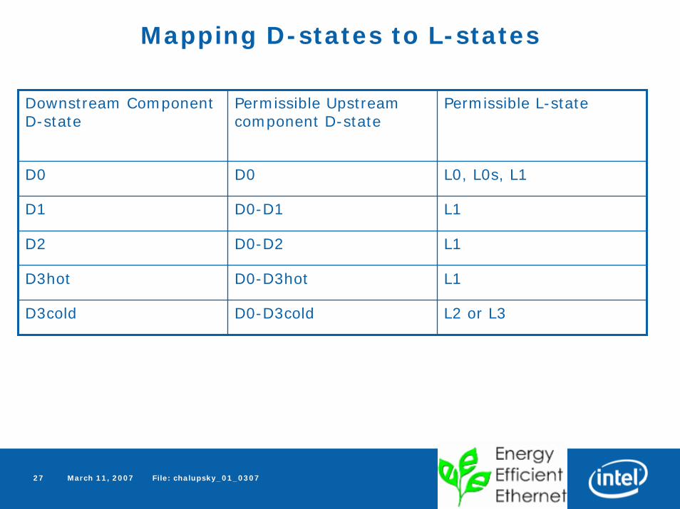
Mapping D-states to L-states
Downstream Component D-state
Permissible Upstream component D-state
Permissible L-state
D0 D0 L0, L0s, L1
D1 D0-D1 L1
D2 D0-D2 L1
D3hot D0-D3hot L1
D3cold D0-D3cold L2 or L3

March 11, 2007 File: chalupsky_01_030728
ACPI Global States and Transitions
S4BIOS_FS4BIOS_REQ
ACPI_DISABLE(SCI_EN=0)
G3 -MechOff
LegacyBoot
(SCI_EN=0)
LegacyBoot
(SCI_EN=0)
ACPI_ENABLE(SCI_EN=1)
Legacy
SLP_TYPx=S5
andSLP_EN
orPWRBTN_OR
WakeEvent
C0
G0 (S0) -Working
G1 -Sleeping
S4S3
S2S1
PowerFailure
ACPIBoot
(SCI_EN=1)
ACPIBoot
(SCI_EN=1)
G2 (S5) -Soft Off
SLP_TYPx=(S1-S4)and
SLP_EN
D0D1
D2D3Modem
D0D1
D2D3HDD
D0D1
D2D3
CDROM
C1C2
C3CPU
C0
BIOSRoutine


![A brief [f]lex tutorial](https://img.dokumen.tips/doc/110x75/56814cf3550346895db9f67d/a-brief-flex-tutorial.jpg)


