Embed Size (px)
Citation preview

C. T. Kuo et al. / Asian Journal of Health and Information Sciences, Vol. 4, No. 1, pp. 36-63, 2009
36
A Blind Robust Watermarking Scheme for 3D Triangular Mesh Models Using 3D Edge Vertex
Detection
CHEN-TSUNG KUO1,3, SHYI-CHYI CHENG2,*, DA-CHUN WU3 AND CHIN-CHUN CHANG2 1Department of Information Management, LongCyuan Veterans Hospital,VAC, Executive Yuan, Taiwan
2Department of Computer Science and Engineering, National Taiwan Ocean University, Taiwan 3Department of Computer and Communication Engineering, National Kaohsiung First University of
Science and Technology, Taiwan
ABSTRACT This paper presents a new blind watermarking scheme on 3D mesh models. The watermark is
hidden within the 3D graphical object by modifying a subset of carefully selected edge vertices in order to resist noise addition, 3D rotation, simplification, cropping and combined attacks. The edge vertices on a triangle mesh refer to the vertices on the creases and corners. The watermark to be embedded is provided as a binary code. A local geometrical disturbance on the selected edge vertices is used to embed the information without destroying the local connectivity. Before watermarking, the edge vertices are detected using the proposed 3D moment-preserving technique and hashed into multiple classes where each of them is used to embed a watermark bit in order to avoid modifying the coordinates of edge vertices clustered in a certain area of the mesh. Experimental results show that the proposed scheme is robust in resisting common attacks on 3D mesh models.
Key words: Digital watermarking, 3D Mesh watermarking, Triangular meshes, 3D Moment-preserving technique.
1. INTRODUCTION
Graphics data are more and more widely applied to a variety of applications, including video gaming, engineering design, architectural walkthrough, virtual reality, e-commerce, and scientific visualization. Many three-dimensional (3D) objects are now represented in 3D meshes to truly reflect the topological structures of the objects. Among various representation tools, triangular meshes provide an effective means to represent 3D mesh models. For digital items, including 3D graphics models, the threat of copying, tampering with, or illegally distributing has generated a highly urgent demand for robust copyright protection methods. It is essential to provide a robust technique for copyright protection and/or content authentication of graphics data in a universal multimedia access framework. One approach to meet this requirement is the use of digital watermarking techniques that aim at generating and embedding an imperceptible signal in the original graphics data. The information to indicate the data owner or an authorized user/distributor can be carried by the embedded watermark. In the past decade, watermarking has been a very active research area and many applications to gray scale or color still images, audio signals, and videos have been proposed in the literature (Cox, Miller
* Corresponding author. E-mail: {csc,cvml}@mail.ntou.edu.tw

C. T. Kuo et al. / Asian Journal of Health and Information Sciences, Vol. 4, No. 1, pp. 36-63, 2009
37
& Bloom, 2001); however, due to the nature of the data representing the cover media, these methods cannot be applied to 3D graphical objects and models. Digital watermarking of 3D mesh objects has not been heavily researched and remains a challenging problem.
The purposes of watermarking 3D graphical objects are twofold: (1) content authentication and tamper proofing; (2) copyright protection. In the former case, the objective is to detect and highlight any regions that have been tampered with (Boon-Lock & Minerva, 1999). Recently, new applications based on this type of watermarking have been considered, including fingerprinting for data queries and retrieval, registration of confidential information, behavioral information for graphical agent systems, etc. In copyright protection applications, the watermarking algorithms aim at embedding a watermark into the cover media such that the watermarked 3D models are perceptually invisible, statistically undetectable and robust against various copyright attacks. Most methods proposed in the recent past for watermarking graphical data belong to this application type (Date, Kanai & Kishinami, 1998; Bors, 2006).
The watermarking algorithms addressing a wide variety of applications can be classified into two categories: (1) watermarking in the transform domain (Praun, Hoppe & Finkelstein, 1999; Ohbuchi, Takahashi, Miyasawa & Mukaiyama, 2001; Ohbuchi, Mukaiyama & Takahashi, 2002; Song, Cho & Kim, 2002) and (2) watermarking in the spatial domain (Ohbuchi, Masuda & Aono, 1997a, 1997b, 1998; Benedens, 1999; Benedens & Busch, 2000; Harte & Bors, 2002; Benedens, 2003; Zafeiriou, Tefas & Pitas, 2005; Bors, 2006). Each approach has its own advantages and disadvantages. In the transform domain watermarking schemes, the watermark is embedded into the 3D mesh models by modifying the transformed frequency coefficients. Although additional forward and inverse transformations are required in the transform domain watermarking schemes, watermarks embedded in invariant-transform domains generally maintain synchronization under mesh smoothing, random noise addition and mesh simplification. On the other hand, watermarking in a spatial domain embeds the watermark into the 3D mesh models by directly modifying and altering the geometry or the topology of triangles or the polygons of the 3D mesh without causing an obvious change in appearance. The main advantage of watermarking in the spatial domain is that less computational cost is required.
Two approaches are used to detect the embedded watermark: (1) blind detection (Bors, 2006; Hubeli & Gross, 2001; Kalivas, Tefas & Pitas, 2003); and (2) informed detection (Benedens, 1999; Harte & Bors, 2002). In blind detection watermarking systems, only a private key is needed in the watermark detection stage. The major advantage of blind watermarking extraction systems is that the time consumption to reconstruct the original object data is not necessary. On the contrary, in informed detection watermarking systems, both the private key and additional information concerning the original models are needed to successfully extract the watermark.
The embedded watermark could be removed due to the inherent geometrical transformations such as 3D object manipulation in computer graphics or computer

C. T. Kuo et al. / Asian Journal of Health and Information Sciences, Vol. 4, No. 1, pp. 36-63, 2009
38
vision or purposeful attacks for illegal usage of the graphical data. There are two transformations including geometrical transformations and topological transformations, the geometrical transformations can be locally or globally applied to rotate, scale, and translate 3D objects. Topological transformations, on the other hand, consist of changing the order of vertices in the object description file, polygon simplification, remeshing or cropping parts of the object. A large variety of attacks can be modeled as noise corruption which accounts for a succession of small perturbations in the location of vertices.
This paper presents a new blind watermarking scheme based on a 3D mesh model. The watermark extraction process is similar to the pattern recognition process in computer vision, except that the original mesh model may not be available to the watermark detector. Edge vertices, which are recognized as an important aspect of human visual perception, are commonly used in region segmentation for 3D models (Kim, Yun & Lee, 2006; Vieira & Shimada, 2005). The edge vertices on a triangle mesh refer to the vertices on the creases and corners. The extracted edge vertices of the input 3D mesh model are used as reference points for both watermarking embedding and detection. The watermark is hidden within the data by modifying a subset of carefully selected edge vertices to resist both geometric distortion and simplification attacks. Although the edge vertices are generally preserved after attacks in order to keep good visual quality of the model, the coordinates of edge vertices might be changed by geometric distortions. Thus, it is important to position the edge vertices in the distorted models. In this paper, we suggest retrieving the watermarked edge vertices by performing the proposed 3D moment-preserving technique (Cheng & Wu, 2005) on the 3D mesh model. Furthermore, before watermarking, the edge vertices are detected and hashed into multiple classes where each of them is used to embed a watermark bit in order to avoid modifying the coordinates of edge vertices clustered in a certain area of the mesh. Experimental results show the robustness of the proposed scheme to resist common attacks on 3D mesh models.
The remainder of this paper is organized as follows. Section 2 presents a brief survey of related work. Section 3 presents the proposed novel watermarking scheme based on detecting edge vertices on mesh models. The error analysis in the system parameter selection is discussed in Section 4. In Section 5, the effectiveness of the proposed method is demonstrated by some experimental tests. Finally, conclusions are drawn in Section 6.
2. RELATED WORKS
Watermarking of 3D graphical objects requires a completely new framework when compared to audio, image or video watermarking (Cox et al., 2001). One of the reasons is the fact that the nature of the data representing the 3D objects is not unique. For example, the authors in Lee, Cho and Nam (2002), proposed a watermarking scheme for 3D NURBS (Nonuniform Rational B-Spline surface)

C. T. Kuo et al. / Asian Journal of Health and Information Sciences, Vol. 4, No. 1, pp. 36-63, 2009
39
graphic data; however, Garcia and Dugelay have attempted to watermark textured attributes of 3D objects (Garcia & Dugelay, 2003).
Attributes of 3D graphical objects can be easily removed, and hence, watermarking on the 3D graphical object geometry is more feasible in protecting copyright of 3D objects. To represent a 3D object as a polygon mesh is popular in computer graphics due to the fact that we have to deal with a relatively low quantity of data. Watermarking algorithms for the authentication of 3D objects has been considered in (Boon-Lock & Minerva, 1999). Wavelet decomposition of 3D mesh objects has been used for 3D watermarking in (Praun et al., 1999). Praun et al. suggested using multi-resolution filters to interpolate surface basis functions for mesh watermarking. For watermarking in the transform domain, algorithms that embed information in the mesh spectral domain using Laplacian have been considered in (Ohbuchi et al., 2001; Ohbuchi et al., 2002). Ohbuchi et al. also proposed different methods for embedding data into 3D models (Ohbuchi et al., 1997a, 1998). A surface normal histogram of a 3D model has been used for watermarking in Benedens (1999).
A blind watermarking algorithm aims at detecting the embedded watermark using only a private key to generate the hidden knowledge of the watermark and the stego object. Most of the algorithms proposed for watermarking 3D objects are nonblind and require a knowledge of the cover media to extract the embedded watermark. Some algorithms include complex registration methods in the watermark detection stage to encounter the attack of affine transform (Benedens, 2003). Recently, several algorithms for watermarking 3D mesh objects using blind detection were proposed in (Benedens & Busch, 2000; Harte & Bors, 2003; Zafeiriou et al. 2005; Bors, 2006). Two robust blind watermarking schemes for copyright protection of 3D mesh object were proposed in (Zafeiriou et al. 2005). Prior to watermark embedding and detection of these algorithms, the object is rotated and translated so that its center of mass and its principal component coincide with the origin and the z-axis of the Cartesian coordinate system. As stated by the authors, this geometrical transform ensures watermark robustness in translation and rotation. Another interesting blind watermarking scheme is proposed in (Bors, 2006). In the first step of the algorithm, a chain of robust feature points and their neighborhood vertices are selected from the 3D mesh object and the vertices are ordered according to some neighborhood localized measurement. The watermark bits generated from a given private key are embedded into these selected vertices by employing local mesh variations based on some criteria to ensure low watermark visibility.
Recently, interesting approaches to 3D blind watermarking based on mesh analysis are presented (Ni, Liu & Zhang, 2007; Lee & Kwon, 2007; Song & Cho, 2008). Ni et al. (2007) transform a 3D mesh into a geometric image by the parameterization and sampling of the model. Conventional 2D image watermarking methods are then used to embed watermark bits on the geometric image. The watermarked model is reconstructed from the embedded geometric image. Lee and Kwon (2007) propose 3D-mesh watermarking based on projection onto convex sets (POCS). Song and Cho (2008) propose an algorithm to embed the watermark into a
C. T. Kuo et al. / Asian Journal of Health and Information Sciences, Vol. 4, No. 1, pp. 36-63, 2009
40
2D image extracted from the 3D model. The authors focus on the development of watermarking which is robust against attacks which, like mesh simplification severely modifies the vertices and connectivity while preserving the appearance of the model. Rather than directly embedding watermarks into 3D mesh geometry, these methods transform the input mesh into other representations which might have many robust watermarking schemes. However, the 3D geometry characteristics might be lost while transforming a 3D model into a 2D image based on a specific projecting scheme.
3. THE PROPOSED 3D WATERMARKING SCHEMES
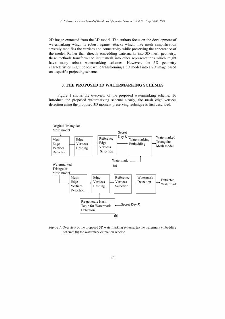
Figure 1 shows the overview of the proposed watermarking scheme. To introduce the proposed watermarking scheme clearly, the mesh edge vertices detection using the proposed 3D moment-preserving technique is first described.
Figure 1. Overview of the proposed 3D watermarking scheme: (a) the watermark embedding
scheme; (b) the watermark extraction scheme.
Original Triangular Mesh model
Edge VerticesHashing
ReferenceEdge VerticesSelection
Watermarking Embedding
Watermarked Triangular Mesh model
Secret Key K
Watermark(a)Watermarked
Triangular Mesh model
Mesh Edge Vertices Detection
Reference Vertices Selection
Watermark Detection Extracted
Watermark
Secret Key KRe-generate Hash Table for Watermark Detection
Mesh Edge Vertices Detection
Edge Vertices Hashing
(b)

C. T. Kuo et al. / Asian Journal of Health and Information Sciences, Vol. 4, No. 1, pp. 36-63, 2009
41
(a) (b)
(c) (d)
Figure 2. The sub-mesh contains edge vertices defining the boundary between two 3Dpatches: (a) the sub-mesh object; (b) modeling the boundary by a step consistingof two surfaces; (c) projecting the vertices onto the plane H passing the center ofthe sub-mesh, whose orientation is set to be the average normal of the sub-mesh;(d) the distribution of distances from the vertices to H, which can be divided intotwo classes.
3.1 Edge Vertices Detection on Triangle Meshes Using Moment-PreservingPrinciple
The edges on the triangle mesh refer to vertices on the ceases and corners,which are common ways of describing the intrinsic characteristics of 3D meshmodel surfaces, and thus can be invariant to translation, rotation, uniform scalingand geometric distortions (Eck et al., 1995; Karni & Gotsman, 2000; Shroder,Zarge & Lorensen, 1992; Garland & Heckbert, 1997; Cohen et al., 1996; Kim et al.,2006; Vieira & Shimada, 2005; Sun, Page, Paik, Koschan & Abidi, 2002). In thewatermarking detection process, without accessing the original model, the edgevertices can serve as referencing points for the synchronization between watermarkembedding and detection.
In our algorithm, to embed watermark into a geometric 3D model efficientlyand robustly, it is necessary to determine the edge vertices of the model. Given anedge vertex v which defines a neighborhood N(v) with its center as v, the vertices ofN(v), could be classified by the principal plane H passing v into two parts, whereeach of them can be modeled as a patch, shown in Figure 2. The algorithm
1H
2H
1H
2H
H
h
d

C. T. Kuo et al. / Asian Journal of Health and Information Sciences, Vol. 4, No. 1, pp. 36-63, 2009
42
approximates the edge strength of v based on the measurement of distance variations from the vertices within N(v) to H. We adopt an edge detector on 3D meshes using the 3D moment-preserving technique which was originally applied to detect edges from color images proposed in our previous work (Cheng & Wu, 2005).
Given a vertex vi = (xi, yi, zi) of a mesh object M, we construct the neighborhood N(vi) of vi as all the vertices from M that are connected to it by means of a path consisting of an edge, two edges, or up to r edges, where r scales the radius of the neighborhood. In our algorithm, the size of the neighborhood affects the accuracy of the estimated edge strength for vi. Increasing r makes the approximation more robust and less sensitive to noise, but also makes more susceptible sharp edges and discontinuities in the original part. In our experiments, we found that r = 3 works well for noisy meshes and this value was used for all the examples.
As shown in Figure 2, we define a step transition between two planes for the region associated with an edge vertex vi, using the geometry of its neighborhood N(vi). The orientations of these two planes might be different due to the fact that the neighborhood N(vi) might contain a sharp edge, a corner, or discontinuities caused by noise. In the first step, the surface normal jn
r at each vertex vj from the
neighborhood N(vi) is calculated. Let a triangle mesh with K vertices, { }K
kkj tvT 1)( == , where tk = (pk1, pk2, pk3) represents a triangle and pk1, pk2, and pk3 are the three respective vertices of the triangle, denoting the triangles connecting directly to the vertex vj. The outward-facing normal of the triangle tk can be computed from the coordinate vectors of pk1, pk2, and pk3. The normal jn
r at the
vertex vj. can be approximated by averaging the triangle normals from )( jvT .
Let ),,( 1111 zyxv = and ),,( 2222 zyxv = denote the representative vertices of H1 and H2, respectively. For processing convenience, before calculating 1v and
2v , all the coordinates of the vertices in the neighborhood N(vi) are subtracted from
iμ and this translates the origin of the 3D space into the center of )( ivNr
. Given the set of vertices vj, j = 1, …, Ni, in N(vi), we can calculate 1v and 2v using the moment-preserving technique. Based on the moment-preserving method and our 3D data processing experience, we select the following set of moments of N(vi) to be preserved
⎟⎟⎠
⎞⎜⎜⎝
⎛= ∑∑∑
∈∈∈ )()()(,,),,(
ijijij vNvj
vNvj
vNvjzyx zyxmmm , (1)
⎟⎟⎠
⎞⎜⎜⎝
⎛= ∑∑∑
∈∈∈ )()()(,,),,(
ijijij vNvjj
vNvjj
vNvjjzxyzxy xzzyyxmmm (2)

C. T. Kuo et al. / Asian Journal of Health and Information Sciences, Vol. 4, No. 1, pp. 36-63, 2009
43
∑∈
=)( ij vNv
jjjxyz zyxm (3)
where vj = (xj, yj, zj) are the coordinates of vj in N(vi). Note that the values of mx, my, and mz are all equal to zero because we have translated the origin into the center of
)( ivNr
in advance. The problem of 3D edge detection using the moment-preserving technique in a given neighborhood N(vi) is to select a plane that separates N(vi) into two parts, where one of them is represented by the representative vertex 1v and the other is represented as 2v . To achieve this goal, the moments defined in (1)-(3) are preserved in the resultant two-level data set N(vi). If two thresholded classes of N(vi) are designated as H1 and H2, F can be expressed as
{ } , ; ,| 2211 HvifvvHvifvvvF ∈=∈== .
We then represent the selected moments of the two-level data set F as
⎟⎠⎞
⎜⎝⎛= ∑ ∑∑
= ==
2
1
2
1
2
1 , ,)ˆ ,ˆ ,ˆ(
l lll
lllllzyx zpypxpmmm , (4)
⎟⎠⎞
⎜⎝⎛= ∑ ∑∑
= ==
2
1
2
1
2
1 , ,)ˆ ,ˆ ,ˆ(
l llll
lllllllzxyzxy xzpzypyxpmmm (5)
∑=
=2
1ˆ
lllllxyz zyxpm (6)
where p1 and p2 denote the fractions of the numbers of the data points in H1 and H2, respectively. And
121 =+ pp . (7)
To estimate the class representatives ) , ,( 1111 zyxv = and ) , ,( 2222 zyxv = based on the proposed moment-preserving technique, we get the following equations
121 =+ pp , xmxpxp =+ 2211 , ymypyp =+ 2211 , zmzpzp =+ 2211 ,
xymyxpyxp =+ 222111 , yzmzypzyp =+ 222111 , zxmxzpxzp =+ 222111 ,
xyzmzyxpzyxp =+ 22221111 , (8)
where all the terms on the left-hand sides of the equalities are the moments of F and all the terms on the right-hand sides are the corresponding ones of N(vi). We have eight variables in the above eight equations, and hence these variables can be obtained by solving the linear system. Because the values of mx, my, and mz are all

C. T. Kuo et al. / Asian Journal of Health and Information Sciences, Vol. 4, No. 1, pp. 36-63, 2009
44
equal to zero, we have
kzz
yy
xx
pp
=−=−=−=1
2
1
2
1
2
2
1 , (9)
kkp+
=11 , k
p+
=1
12 , (10)
xymyxk =11 , yzmzyk =11 , zxmxzk =11 (11)
yz
xyz
mm
xk =− 1)1(, zx
xyz
mm
yk =− 1)1( , xy
xyz
mm
zk =− 1)1(. (12)
Combining (11) and (12), we have
012 =+− ckk , (13)
where zxyzxy
xyz
mmmm
c2
2 += . Therefore, the value of k can be solved as
,2
42 −+=
cck
if p1 ≥ p2 ; (14)
,2
42 −−=
cck if p1 < p2. (15)
A problem arises naturally: we do not know which equation ((14) or (15)) should be used to solve for the value of k, since we have no idea about whether p1 is larger than p2 or not. The relationship between p1 and p2 can be determined by a vertex counting method (Cheng & Wu, 2005). The method is described as follows.
Assume p1 > p2. Then the vertex ) , ,( 1111 zyxv = must be the representation of the larger group of data. Let Cpx, Cpy and Cpz be the numbers of vertices in H1 with positive coordinate component values x, y and z, respectively, and Cnx , Cny and Cnz are the numbers of vertices in H2 with negative coordinate component values x, y and z, respectively. Then, the rules for determining the relationship between p1 and p2 are
⎩⎨⎧
<++≥++≥
.,;)()( ,
21
21
otherwiseppCnCnCnCpCpCpifpp zyxzyx (16)
Once the representative vertices 1v and 2v are determined, the vertices vj, j = 1, 2, …, Ni, in the neighborhood N(vi) are classified according to the following decision rule:

C. T. Kuo et al. / Asian Journal of Health and Information Sciences, Vol. 4, No. 1, pp. 36-63, 2009
45
⎩⎨⎧
∈≤∈
otherwiseHvvvGDvvGDifHv
j
jjj
:) ,( ) ,( :
2
211 (17)
where ) ,( ba vvGD measures the geodesic distance (Vieira & Shimada, 2005) between the vertices va and vb.
(a) (b) Figure 3. Types of transition edge in a sub-mesh object: (a) a step transition edge; (b) a
corner edge.
Let 1nr
and 2nr
denote the normals of the planes H1 and H2, respectively. We approximate 1n
r and 2n
r by averaging the normals of the vertices belonging
to H1 and H2, respectively. That is:
∑∈
=11
11
Hvj
j
nN
nrr
, ∑∈
=22
21
Hvj
j
nN
nrr
(18)
where N1 and N2 are the numbers of vertices belonging to H1 and H2, respectively. Note that the distances from a vertex v to H1 and H2 can be obtained by
⎩⎨⎧
+⋅=+⋅=
. )(; )(
222
111
dvnvHdvnvH
r
r
(19)
Because 1v and 2v are on H1 and H2, respectively, the values of d1 and d2 can be calculated as
),(),( 221121 vnvndd ⋅−⋅−=rr
. (20)
2nr
1v
2v
1nrH1
H2
iv
2nr
1v
2v
1nr iv
2H
1H

C. T. Kuo et al. / Asian Journal of Health and Information Sciences, Vol. 4, No. 1, pp. 36-63, 2009
46
The vertex vi is defined to be an edge vertex if its neighborhood N(vi) contains an edge that defines the boundary of two regions. In this work, shown in Figure 3, the vertex vi is an edge vertex if the edge strength (ES) is large. ES of vi is defined as
||))(||)((||21
21|))(||)((| ii vHvHiii evHvHES −−+= . (21)
There are two cases to enlarge the value of ESi: (1) the vertex vi is near the bending point of the transition edge (cf. Figure 3); and (2) the sum of distances from vi to H1 and H2 is large. The vertex vi is determined to be an edge vertex if ESi > τ where τ is a threshold value and set to be the average edge strength for all the vis in the mesh.
3.2 Watermark Embedding Process
Basically, we embed the watermark bits on the selected edge vertices which are invariant to affine transformations such as rotation, translation, and scaling. The edge vertices should be properly ordered to embed watermark bits one by one. A trivial solution to order the edge vertices is to sort these vertices vis according to their ES values (defined in (21)). However, this might result in a potential problem: the embedded edge vertices might be clustered together because their ES values are similar to one another for nearby edge vertices. This will decrease the robustness of the watermarking scheme to counter the cropping attack. To solve this problem, we suggest using an ES hash table, shown in Figure 4, which is obtained from a learning procedure or uniformly partitioning the ES values, for synchronizing the watermark embedding and detection processes.
Let watermark W be a binary image with L = w × h bits, W = (w1, w2, ..., wL) and wi ∈ (0, 1). The ES hash table, which was generated by uniformly partitioning the ES values and ordered in advance, is used to determine the locations where the watermark bits are embedded. Let the size of the ES hash table be R, R >> L. As shown in Figure 4, the edge vertices of the original mesh object are mapped into the closest bucket in the ES hash table in terms of the corresponding ES values. Then, a bit mask K = (k1, k2, …, kR) is generated. The value of ki is 1 if the i-th bucket of the ES hash table is hit by some edge vertices of the original mesh object; otherwise, ki = 0. The bit mask K is used as the DES encryption key for two purposes: permuting the watermark and determining the positions of edge vertices for embedding the watermark.
During the watermark extraction phase, the edge vertices of the watermarked mesh object are also hashed into the closest buckets in the ES hash table, where the secret key K is used to indicate the buckets of the hash table containing watermarked edge vertices. The ES hash table plays a role in synchronizing the watermark embedding and detection processes. The synchronization scheme is very robust, even when we attack the watermarked mesh model by some severe geometric distortions such as centered cropping. Furthermore, the ES hash table is given in advance in both the watermark embedding process and the watermark extraction process. This means that the hash table does not introduce extra information sent to the receiver end for detecting the embedded watermark.

C. T. Kuo et al. / Asian Journal of Health and Information Sciences, Vol. 4, No. 1, pp. 36-63, 2009
47
Given an edge vertex vi, the watermark bit wi is embedded into vi by modifying their coordinate values, if necessary, such that:
…ESHashTable
Edge vertices of the watermarked mesh model
Edge vertices of the host mesh model… … … ……
… … … …
Figure 4. The scheme to synchronize the watermarked edge vertices of the original mesh model with the edge vertices of the watermarked mesh model using the SD hash table.
(a) (b)
Figure 5. The updating rule for embedding (a) a bit of 1, and (b) a bit of 0.
H2
H11nr
2nr
|ˆ| ii vv −
iv
iv̂ H2
H11nr
2nr
|ˆ| ii vv −iv
iv̂

C. T. Kuo et al. / Asian Journal of Health and Information Sciences, Vol. 4, No. 1, pp. 36-63, 2009
48
(a) (b) (c)
Figure 6. A watermark sample is embedded in edge vertex vi: (a) original mesh; (b) the mesh after embedding a watermark bit ‘0’; (c) the mesh after embedding a watermark bit ‘1’.
⎩⎨⎧
=−≤−=≥−
0|)ˆ(||)ˆ(|1|)ˆ(||)ˆ(|
21
21
iii
iii
wifvHvHwifvHvH
αα
(22)
where |)ˆ(| 1 ivH ( |)ˆ(| 2 ivH ) denotes the distance from the new iv̂ to H1 (H2) along the direction of 1n
r( 2nr
) and α is a positive constant. If the original vi satisfies (26), we do not update the coordinates of vi. The underlying idea of (22) is to move the edge vertex vi, if necessary, along the direction )( ivN
r such that the new iv̂ is
closer to H1 (H2) when embedding a 0 (1) bit. The minimal distortion embedding condition is ensured by using the local gradient to the surface that models the embedding region (Bors, 2006). When embedding a bit of 1, in the case when the vertex dose not initially fulfill (22), shown in Figure 5, the updating rule is given by:
)(ˆ iii vNvvr
β+= (23)
where the value of β is:
)1)(()()(
2121
12
nnppvHvH iirr
⋅−−−+
=αβ . (24)
Similarly, when embedding a bit of 0 to fulfill (26), the updating rule is:
)(ˆ iii vNvvr
β−= (25)
where the value of β is:
)1)(()()(
2121
21
nnppvHvH ii
rr⋅−−−−
=αβ . (26)
The embedding rules of (23) and (24) ensure a minimal local distortion in the graphical object by using a direction of change that is parallel with the average

C. T. Kuo et al. / Asian Journal of Health and Information Sciences, Vol. 4, No. 1, pp. 36-63, 2009
49
normal )( ivNr
of the neighborhood N(vi). Note that the larger the value of β, the better the robustness of the watermark. On the other hand, a large β may lead to visible artifacts in the 3-D graphical object. A watermark sample embedded in the vertex vi using (23) and (24) is shown in Figure 6.
3.3 Watermark Extracting Process
The purpose of the watermark extracting process is to recover the information that has been embedded in the 3D mesh model. The proposed watermarking method is blind and does not require the original mesh model for watermark extraction. First, the secret key determines the positions of edge vertices that were used to embed the watermark bits. The ith 1’s bit of the secret key means the edge vertices with the values of edge strength (ES) being hashed into the ith buckets of the hash table were used to embed the ith watermark bit. Let P denote the generic sub-hash table consisting of the buckets whose corresponding bit in the secret key is 1. Before extracting the watermark, for each edge vertex of the watermarked mesh object, we must perform the edge vertex mapping process to find its closest bucket in P in terms of ES values. Note that it is possible to have some buckets in P without any edge vertices mapping onto them due to geometric distortions such as cropping. That means the corresponding watermark bits are omitted. In this case, these omitted watermark bits will be predicted according to the values of their neighboring bits. The detail process of retrieving watermark is as follows: (a) Perform the edge vertex detection on the watermarked graphical object using
the proposed edge detector mentioned above. (b) Produce the ES hash table P using the secret key K. P consists of those buckets
whose corresponding bit in the secret key is 1. (c) Map each edge vertex onto the closest bucket in P according to the ES value of
the vertex. (d) For each watermark bit wi, i = 1, …, w × h, perform the following steps:
1. Find the edge vertex set Ei that is comprised of those edge vertices whose ES values are mapped onto the ith bucket of P.
2. If Ei is not empty, for each vertex vj in Ei, perform the following process to determine the value of wi according to vj:
⎩⎨⎧
<−=≥−=
0|)(||)(|,00|)(||)(|,1
21
21
jji
jji
vHvHifwvHvHifw
(27)
where H1 and H2 are the planes obtained from the neighborhood of vj using the proposed 3D moment-preserving process. H1(vj) and H2(vj) are the distances from vj to H1 and H2, respectively. The resulting watermark bit is 1 if most of the edge vertices in Ei vote it to be 1 according to (31); otherwise, the ith watermark bit is 0.
(e) If Ei is empty, label iw to be omitted.
C. T. Kuo et al. / Asian Journal of Health and Information Sciences, Vol. 4, No. 1, pp. 36-63, 2009
50
(a) (b) (c)
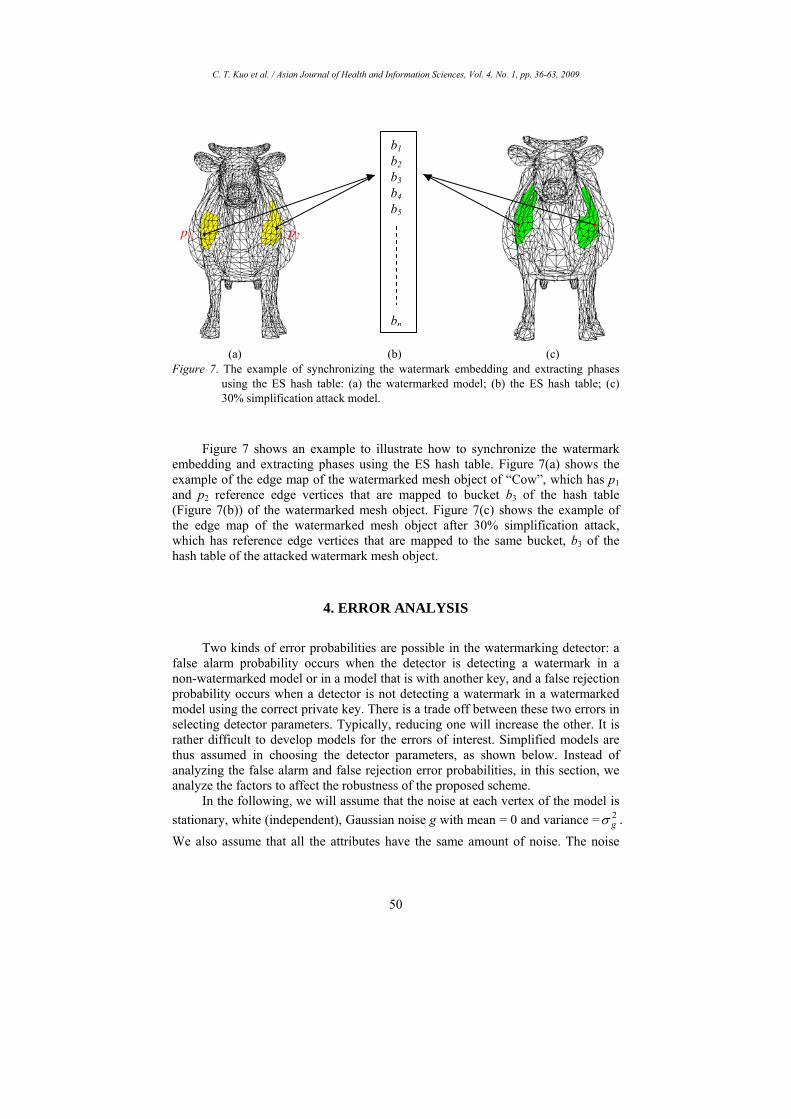
Figure 7. The example of synchronizing the watermark embedding and extracting phases using the ES hash table: (a) the watermarked model; (b) the ES hash table; (c) 30% simplification attack model.
Figure 7 shows an example to illustrate how to synchronize the watermark embedding and extracting phases using the ES hash table. Figure 7(a) shows the example of the edge map of the watermarked mesh object of “Cow”, which has p1 and p2 reference edge vertices that are mapped to bucket b3 of the hash table (Figure 7(b)) of the watermarked mesh object. Figure 7(c) shows the example of the edge map of the watermarked mesh object after 30% simplification attack, which has reference edge vertices that are mapped to the same bucket, b3 of the hash table of the attacked watermark mesh object.
4. ERROR ANALYSIS
Two kinds of error probabilities are possible in the watermarking detector: a false alarm probability occurs when the detector is detecting a watermark in a non-watermarked model or in a model that is with another key, and a false rejection probability occurs when a detector is not detecting a watermark in a watermarked model using the correct private key. There is a trade off between these two errors in selecting detector parameters. Typically, reducing one will increase the other. It is rather difficult to develop models for the errors of interest. Simplified models are thus assumed in choosing the detector parameters, as shown below. Instead of analyzing the false alarm and false rejection error probabilities, in this section, we analyze the factors to affect the robustness of the proposed scheme.
In the following, we will assume that the noise at each vertex of the model is stationary, white (independent), Gaussian noise g with mean = 0 and variance = 2
gσ . We also assume that all the attributes have the same amount of noise. The noise
b1 b2 b3 b4 b5 bn
p1 p2

C. T. Kuo et al. / Asian Journal of Health and Information Sciences, Vol. 4, No. 1, pp. 36-63, 2009
51
will affect the system in three respects: the edge vertex detection, the determination of principal plane using the 3D moment-preserving process, and the watermark extraction scheme.
As mentioned in Section 3, the moments of the vertex neighborhood N(vi) mx, my, mz, mxy, myz, mzx and mxyz are used to calculate the principal plane. It is easy to prove that the expected values of the moments mxy, myz, mzx are multiplied by 2
gσ ; the expected values of the moments mx, my, mz remain zero; and the expected value of mxyz is multiplied by 3
gσ . For example, the expected value of the moment mxy with noise can be computed from its definition:
2
),,( 3))((~
gxySzyx
xy mygxgEm σ=⎥⎦
⎤⎢⎣
⎡= ∑
∈. (28)
Thus the key parameter c, shown in (13) used to calculate parameters p1 and p2, which are further used to calculate the principal planes, is not affected by the noise. Thus the principal planes are stable with respect to multiplied Gaussian noise. On the contrary, when the noise is additive, the expected values of the noise moments are their original values plus some noise term, i.e., the noise moment
2~gxyxy mm σ+= . In this case, the values of the parameters p1 and p2 are slightly
changed by the noise. However, the noise essentially does not affect the principal planes because the values of the moments are much larger than the value of gσ .
Considering a vertex, vi, which was an embedded watermark bit, the difference between H1(vi) and H2(vi) is at least α. The value of α is used to resist the attack on the noise. If the additive zero-mean Gaussian noise is applied, the expected average difference between distances from iv to the planes H1 and H2 would be
[ ] [ ] α=−=+−+ )()()()( 2121 iiii vHvHEgvHgvHE , if vi is embedded a ‘1’ bit;
[ ] [ ] α−=−=+−+ )()()()( 2121 iiii vHvHEgvHgvHE , if vi is embedded a ‘0’ bit.
Similarly, it is simple to verify that the variation 2ασ of distances from vi to the
planes H1 and H2 would be )cos1(2 2 ϕσ −g , where ϕ is the angle between the
normal vectors of H1 and H2. Note that the value of ασ would be 0 when the value of ϕ is zero. This implies that the watermark is better embedded in an edge vertex whose neighboring vertices comprise two parallel planes using the proposed watermarking scheme. On the contrary, a corner edge vertex is more sensitive to noise, and thus we do not suggest embedding watermark bits on corner edge vertices as this may introduce visible distortion on the watermarked 3D mesh.

C. T. Kuo et al. / Asian Journal of Health and Information Sciences, Vol. 4, No. 1, pp. 36-63, 2009
52
5. EXPERIMENTAL RESULTS
Several simulations are performed on an Intel PENTIUM 4-2.8GHz PC with 512 MB main memory to evaluate the performance of the proposed watermarking scheme. We conducted a series of experiments to test the proposed watermarking method for robustness and imperceptibility. Figure 8 shows three example mesh models: “Dragon” (12,406 vertices, 24,125 faces), “Horse” (9,924 vertices, 19,734 faces), “Stanford Bunny” (10,450 vertices, 20,743 faces) (Stanford Bunny, 2003), and the watermark for embedding. The watermark is further presented in two forms, namely, 16*16 pixel (256 Bits) and 32*32 pixel (1024Bits) binary images, to test the performance of the proposed watermarking scheme.
(a) (b) (c) (d)
Figure 8. Example 3D mesh models and the watermark for embedding: (a) Dragon; (b) Horse; (c) Bunny; (d) the watermark binary image.
Table 1. Robustness comparison for typical algorithms on watermarking 3D mesh objects where NR, ID, and BD denote no information in the original papers, informed detection, and blind detection, respectively
Topological Transformation Signal Processing Attacks Methods
Geometrical Transformation Cropping Remesh Mesh
SimplifyNoise
AdditionSmoothing
Remark
Praun et al., 1999 No NR No No Yes Yes ID Ohbuchi et al., 2002 Yes Yes Yes Yes Yes Yes ID Benedens, 2003 Yes NR Yes Yes Yes Yes ID Benedens & Busch, 2000 Yes NR Yes Yes Yes Yes BD Ohbuchi et al., 2002 Yes NR No No Yes Yes ID Zafeiriou et al., 2005 Yes NR NR Yes NR NR BD Bors, 2006 Yes Yes NR NR Yes NR BD Proposed method Yes Yes Yes Yes Yes Yes BD
Table 2. The SNR values for each model Mesh
Models Watermark
length Proposed method
Benedens and Busch’ method
Bors’s method
Dragon 256 58.42 53.35 52.24 Horse 256 57.06 55.02 49.05 Bunny 256 61.39 58.13 55.43 Dragon 1024 53.52 50.30 48.67 Horse 1024 51.08 51.02 47.88 Bunny 1024 55.15 54.53 51.42

C. T. Kuo et al. / Asian Journal of Health and Information Sciences, Vol. 4, No. 1, pp. 36-63, 2009
53
Table 3. Attack types and parameters Attack types Parameters Noise 0.5% 1% 2% Simplification 20% 50% 70% 90% Cropping 20% 30% 40% 50%
Factor 0.5 1.5 2 0.5 1.5 2 Scaling Axis X Y Z X Y Z Cropping 50% 40% 30% 20% Combined Cropping and
noise attacks noise 0.5% 0.5% 1% 1% Simplification 50% 40% 30% Scaling 0.5 X 1.5 X/Y 2.0 X/Y/Z
Combined Simplification ,Scaling and noise attacks noise 0.5% 1% 2%
The common attacks to 3D mesh watermarking schemes include geometrical transformations, topological transformation and signal processing algorithms. Geometrical transformations include affine transformations such as rotation, scaling, translation and their combinations. Topological transformations include cropping parts of the object, reordering vertices in the object description files and more sophisticated attacks such as mesh simplification. Signal processing algorithms include object compression and encoding, smoothing and noise corruption for intentional attacks. Actually, some algorithms for watermarking 3D mesh objects by perturbing local mesh connectivity can be modeled as noise corruption. Table 1 summarizes the robustness comparison to counter the attacks on 3D watermarking for the typical methods reviewed in this paper and the proposed method. Most of the existing 3D watermarking algorithms might be robust to certain attacks, but not others. Topology-based watermarking algorithms are usually not robust to affine transformations (Benedens & Busch, 2000). A non-blind approach can provide better robustness to various attacks; however, blind watermark detection schemes are more suitable to practical applications.
The SNR (Signal to Noise Ratio) has been used to measure watermark perceptibility:
⎟⎟⎠
⎞⎜⎜⎝
⎛
−+−+−
++=
∑
∑
=
=Ni iiiiii
Ni iii
zzyyxxzyx
SNR1
2221
222
10 )~()~()~(()(
log10 (29)
where N is number of vertices on a mesh model, (xi, yi, zi) and ( iii zyx ~,~,~ ) are the coordinates of the vertex vi before and after the watermark embedding, respectively. In order to verify the effectiveness of the proposed watermark scheme, the methods proposed by Benedens and Busch (2000) and Bors (2006) are also simulated for performance comparison. The SNR values of each test model are summarized in Table 2. Accordingly, the proposed method produced better watermarked mesh models in terms of SNR measurement.
To test the robustness of the proposed watermarking scheme, the typical attack types and their parameter setting used in our experiments are listed in Table 3. Based on the watermark sequence wi and the detection sequence si, it is decided in terms of detection ratio whether the watermark under investigation is embedded in the mesh model or not. The false detection signal ew is equal to 1 if a
C. T. Kuo et al. / Asian Journal of Health and Information Sciences, Vol. 4, No. 1, pp. 36-63, 2009
54
watermarked vertex vi is falsely detected and 0 otherwise.
⎩⎨⎧ ≠
=otherwise. 0
if 1)( ii
iwsw
ve (30)
The detection ratio Dw is defined as the ratio of the number of correctly detected vertices to the number of the watermarked vertices in the mesh model:
))(1(1∑ −=i
iww
w veN
D (31)
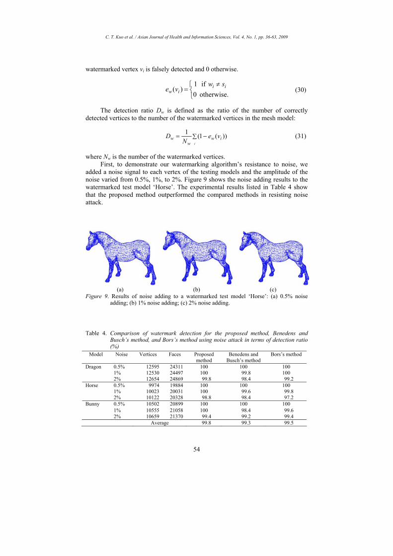
where Nw is the number of the watermarked vertices. First, to demonstrate our watermarking algorithm’s resistance to noise, we
added a noise signal to each vertex of the testing models and the amplitude of the noise varied from 0.5%, 1%, to 2%. Figure 9 shows the noise adding results to the watermarked test model ‘Horse’. The experimental results listed in Table 4 show that the proposed method outperformed the compared methods in resisting noise attack.
(a) (b) (c)
Figure 9. Results of noise adding to a watermarked test model ‘Horse’: (a) 0.5% noise adding; (b) 1% noise adding; (c) 2% noise adding.
Table 4. Comparison of watermark detection for the proposed method, Benedens and Busch’s method, and Bors’s method using noise attack in terms of detection ratio (%)
Model Noise Vertices Faces Proposed method
Benedens and Busch’s method
Bors’s method
0.5% 12595 24311 100 100 100 1% 12530 24497 100 99.8 100
Dragon
2% 12654 24869 99.8 98.4 99.2 0.5% 9974 19884 100 100 100 1% 10023 20031 100 99.6 99.8
Horse
2% 10122 20328 98.8 98.4 97.2 0.5% 10502 20899 100 100 100 1% 10555 21058 100 98.4 99.6
Bunny
2% 10659 21370 99.4 99.2 99.4 Average 99.8 99.3 99.5

C. T. Kuo et al. / Asian Journal of Health and Information Sciences, Vol. 4, No. 1, pp. 36-63, 2009
55
(a) (b) (c) (d)
Figure 10. Results of simplification attack to a watermarked test model ‘Dragon’ for the proposed watermark scheme: (a) 20% reduction; (b) 50% reduction; (c) 70% reduction; (d) 90%
Table 5. Comparison of watermark detection for the proposed method, Benedens and Busch’s method, and Bors’s method using simplification attack in terms of detection ratio (%)
Model Simplification Vertices left
Faces left
Proposed method
Benedens and Busch’s method
Bors’s method
20% 9543 18717 98.2 94.2 96.0 50% 5964 11663 94.3 88.5 86.4 70% 3579 6972 72.2 61.3 65.9
Dragon
90% 1193 2285 66.6 54.3 59.0 20% 7939 15773 97.2 95.4 97.3 50% 4962 9828 86.4 84.8 85.2 70% 2977 5872 73.2 71.8 72.7
Horse
90% 992 1951 58.2 56.2 54.5 20% 8360 16567 97.2 94.5 96.5 50% 5225 10310 84.6 82.6 83.8 70% 3135 6142 76.7 69.4 74.7
Bunny
90% 1045 2030 66.5 61.5 63.5 Average 80.94 76.21 77.96
Second, we performed a simplification attack to test the robustness of the watermarked mesh models. The fractions of vertices of the watermarked models were reduced from 20%, 50%, to 70% using a simplification process. Figure 10 shows an example of the simplified watermarked test model ‘Dragon’ for the proposed watermarking scheme. The experimental results listed in Table 5 show that the proposed method again outperformed the compared methods --Bors’s method and Benedens and Busch’s method, in resisting simplification attack. In addition, all the simulated methods performed badly when too many feature vertices were removed from the mesh models.
We tested the robustness of all simulated algorithms in resisting different degrees of cropping attacks. Before watermark detection, four cropped versions of each watermarked mesh model were obtained by removing the vertices in the original watermarked model by 20%, 30%, 40%, and 50%. As an example, the four cropped versions of the watermarked model ‘Bunny’ are shown in Figure 11. Table 6 shows the watermark detection results for the three compared algorithms using
C. T. Kuo et al. / Asian Journal of Health and Information Sciences, Vol. 4, No. 1, pp. 36-63, 2009
56
the cropping attacks. These results again demonstrate that the proposed algorithm counters cropping attacks with high watermark detection rate.
We have also tested the algorithm’s robustness against scaling attacks in four different parameter settings. They are (1) scaling down the models with a factor 0.5 along the X-axis, (2) scaling up the models with a factor 1.5 along the Y-axis, (3) scaling up the models with a factor 2.0 along the Z-axis, and (4) the mixed scaling attack including scaling factors 0.5 in X-axis, 1.5 in Y-axis, and 2.0 in Z-axis. An example of applying the scaling distortion on the test model ‘Dragon’ that includes the watermark bits using the proposed method is shown in Figure12. Table 7 compares the performance of the proposed method, Benedens and Busch’s method, and Bors’s method to counter scaling attacks in terms of watermark detection ratio (%). Accordingly, the proposed method resists scaling attacks with high detection rate value.
Finally, to test the algorithm’s robustness against combined attacks, we first performed combined cropping and noise adding attacks on the watermarked models. The noise amounts to disturb the coordinates of vertices of the test models were 0.5% and 1%. The cropping attacks in the test included 50%, 60%, 70%, and 80% cropping. Table 8 shows the watermark detection results for the compared methods based on the combined attacks. Although the performance of the proposed method degrades slightly, the proposed method outperforms other methods and is still robust against these combined attacks. To further verify the effectiveness of the proposed method, other combined cropping, scaling, and noise adding attacks on the watermarked models were tested, as shown in Figure 13 and Table 9. In this case, the proposed method still outperformed the compared methods. Figure 14 shows examples of the extracted watermarks under different attacks using the proposed method, Benedens and Busch’s method, and Bors’ method based on the experimental models. The qualities of the extracted watermarks using the proposed method are substantially better than those using other methods.
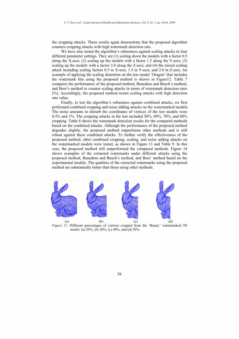
(a) (b) (c) (d)
Figure 11. Different percentages of vertices cropped from the ‘Bunny’ watermarked 3D model: (a) 20%, (b) 30%, (c) 40%, and (d) 50%.

C. T. Kuo et al. / Asian Journal of Health and Information Sciences, Vol. 4, No. 1, pp. 36-63, 2009
57
Table 6. Performance comparison for the proposed method, Benedens and Busch’s method, and Bors’s method to counter cropping attacks in terms of detection ratio (%)
Model Cropping Vertices left
Faces left
Proposed method
Benedens and Busch’s method
Bors’s method
20% 9935 19183 99.1 93.3 98.5 30% 8704 16721 96.0 87.6 93.5 40% 7466 14225 88.4 81.9 83.7
Dragon
50% 6218 11749 85.3 79.0 80.3 20% 7989 15786 99.0 97.3 98.4 30% 6967 13812 96.2 95.2 93.2 40% 5984 11838 91.3 87.0 88.1
Horse
50% 4972 9869 86.4 83.5 84.2 20% 8412 16584 97.2 96.5 95.8 30% 7336 14525 96.1 95.8 94.6 40% 6301 12445 93.8 92.4 90.2
Bunny
50% 5235 10369 87.2 86.0 85.5 Average 93.0 89.6 90.5
(a) 0.5/X (b) 1.5/Y (c) 2.0/Z (d) 0.5X/1.5Y/2.0Z
Figure 12. Results of performing scaling attacks on the watermarked model ‘Dragon’: (a) 50% scaling down along the X-axis; (b) 150% scaling up along the Y-axis; (c) 200% scaling up along the X-axis; (d) hybrid of (a) to (c).
Table 7. Performance comparison for the proposed method, Benedens and Busch’s method, and Bors’s method to counter scaling attacks in terms of detection ratio (%)
Model Scaling Factor Vertices left
Faces left
Proposed method
Benedens and Busch’s method
Bors’s method
0.5 X 12406 24125 100 98.5 98.7 1.5 Y 12406 24125 100 97.3 96.8 2.0 Z 12406 24125 98.2 95.2 94.3
Dragon
0.5 X/1.5Y/2.0Z 12406 24125 97.3 88.2 88.4 0.5 X 9924 19734 100 97.9 98.2 1.5 Y 9924 19734 99.8 95.1 96.8 2.0 Z 9924 19734 99.4 94.2 97.2
Horse
0.5 X/1.5Y/2.0Z 9924 19734 98.5 82.5 87.0 0.5 X 10450 20743 100 98.0 98.5 1.5 Y 10450 20743 99.6 96.2 96.8 2.0 Z 10450 20743 99.2 94.7 95.8
Bunny
0.5 X/1.5Y/2.0Z 10450 20743 98.9 86.9 87.7 Average 99.24 93.73 94.68

C. T. Kuo et al. / Asian Journal of Health and Information Sciences, Vol. 4, No. 1, pp. 36-63, 2009
58
Table 8. Performance comparison for the proposed method, Benedens and Busch’s method, and Bors’s method to counter combined cropping and noise adding attacks in terms of detection ratio (%).
Model cropping and noise
Vertices left
Faces left
Proposed method
Benedens and Busch’s method
Bors’s method
50% 0.5% 6268 11915 83.2 78.2 79.4 40% 0.5% 7516 14417 87.5 80.1 82.4 30% 1% 8818 17083 92.2 85.7 89.7
Dragon
20% 1% 10054 19552 95.2 92.3 94.3 50% 0.5% 5014 9972 84.1 81.3 82.4 40% 0.5% 6012 11967 89.4 83.8 85.2 30% 1% 7052 14095 90.0 88.0 89.1
Horse
20% 1% 8038 16061 94.8 90.5 91.2 50% 0.5% 5279 10455 83.9 81.5 80.8 40% 0.5% 6330 12563 89.8 87.8 89.6 30% 1% 7425 14804 92.4 90.4 91.4
Bunny
20% 1% 8467 16882 94.2 92.0 93.5 Average 89.73 85.97 87.42
Table 9. Performance comparison for the proposed method, Benedens and Busch’s method, and Bors’s method to counter combined cropping, scaling, and noise adding attacks in terms of detection ratio (%).
Model Cropping ,Scaling and noise adding attacks
Vertices left
Faces left
Proposed method
Benedens & Busch’s
method
Bors’s method
50% 0.5 X 0.5% 6268 11915 79.2 75.2 74.4 40% 1.5 X/Y 1% 7568 14573 82.1 79.5 78.6
Dragon
30% 2.0 X/Y/Z 2% 8932 17425 85.3 81.5 82.9 50% 0.5 X 0.5% 5014 9972 78.1 76.2 75.4 40% 1.5 X/Y 1% 6053 12091 81.8 78.5 79.3
Horse
30% 2.0 X/Y/Z 2% 7145 14374 83.6 83.2 84.2 50% 0.5 X 0.5% 5279 10455 78.4 73.2 71.4 40% 1.5 X/Y 1% 6375 12698 80.1 78.1 75.1
Bunny
30% 2.0 X/Y/Z 2% 7524 15100 83.8 82.2 83.6 Average 81.38 78.62 78.32
(a) (b) (c)
Figure 13. Results of performing combined cropping (C), scaling (SC), and noise adding (N) attacks on the watermarked model ‘Bunny’: (a) C:50%, SC:0.5/X, N:0.5%; (b) C: 40%,SC: 0.5/XY, N:1%; (c) C:30%, SC: 2.0/XYZ, N:2%.

C. T. Kuo et al. / Asian Journal of Health and Information Sciences, Vol. 4, No. 1, pp. 36-63, 2009
59
(a)
(b)
(c)
(d)
Figure 14. Examples of the extracted watermarks for simulated methods under different attacks: (a) simplification 50% (b) noise adding 2%; (c) cropping 50%; (d) scaling 0.5X/1.5Y/2.0Z. The images listed from left to right in each of Figures. (a)-(d) are the attacked model, the extracted watermarks using the proposed method, Benedens and Busch’s method, and Bors’s method.

C. T. Kuo et al. / Asian Journal of Health and Information Sciences, Vol. 4, No. 1, pp. 36-63, 2009
60
6. CONCLUSION
In this paper, we propose a new robust blind watermark scheme for 3D triangular mesh models using the 3D moment-preserving principle. The advantages of the proposed method include: (1) we have defined the edge strength of each vertex based on the variation of distances from the vertices within a neighborhood from their common principal planes; (2) we have presented an edge detector on 3D meshes using 3D moment-preserving technique; (3) we have used an ES hash table to synchronize the watermark embedding and extracting processes such that we do not require the original mesh model for watermark extraction; (4) by exploiting the human visual system, we have provided a transparent watermark that is also robust enough to resist common attacks.
Our watermarking algorithm has proven to be robust against a wide variety of attacks, including noise addition, simplification, cropping, transformation and combined attacks. Experimental results show that both the transparency and robustness requirements for watermarking are well satisfied in the proposed scheme. Higher robustness is achieved by embedding watermark bits in 3D edge vertices, which are often preserved on general 3D mesh transformations in order to maintain good visual qualities of the attacked models.
REFERENCES
Benedens, O. (1999). Geometry-Based Watermarking of 3-D Polygonal Models. IEEE Comput. Graph. Appl., special issue on image security, 19(1), 46-45.
Benedens, O., & Busch, C. (2000). Towards Blind Detection of Robust Watermarks in Polygonal Models. Proc. EUROGRAPHICS 2000, 199-209.
Benedens, O. (2003). Robust Watermarking and Affine Registration of 3D Meshes. Proc. Information Hiding, 177-195.
Boon-Lock, Y., & Minerva, M. (1999). Watermarking for 3D objects for Verification. IEEE Comput. Graph. Appl., special issue on image security, 19(1), 36-45.
Bors, A. G. (2006). Watermarking Mesh-Based Representations of 3-D Objects Using Local Moments. IEEE Trans. Image Process., 15(3), 687-701.
Cheng, S. -C., & Wu, T. -L. (2005). Subpixel edge detection of color images by principal axis analysis and moment-preserving principle. Pattern Recognition, 38, 527-537.
Cohen, J., Varshney, A., Manocha, D., Turk, G., Agarwal, H., Weber, P., Brooks, F., & Wright, W. (1996). Simplification Envelopes. Proc. of SIGGRAPH’96, 119-128.
Cox, I. J., Miller, M. L., & Bloom, J. A. (2001). Digital Watermarking. New York, USA: Morgan Kaufmann.
Date, H., Kanai, S., & Kishinami, T. (1998). Digital Watermarking for 3D Polygons Model Using Multiresolutional Wavelet Decomposition. Proc. Sixth IFIP WG 5.2 GEO-6, 296-307.
C. T. Kuo et al. / Asian Journal of Health and Information Sciences, Vol. 4, No. 1, pp. 36-63, 2009
61
Eck, M., DeRose, T., Duchamp, T., Hoppe, H., Lounsbery, M., & Stuetzle, W. (1995). Multiresolutional Analysis of Arbitrary Meshes. Proc. of SIGGRAPH’95, 173-182.
Garcia, E., & Dugelay, J. -L. (2003). Texture-based watermarking of 3D Video Objects. IEEE Trans. Circuits Sys. Video Technol., 13(8), 853-866.
Garland, M., & Heckbert, P. S. (1997). Surface Simplification Using Quadratic Error Metrics. Proc. of SIGGRAPH’97, 189-198.
Harte, T., & Bors, A. G. (2002). Watermarking 3-D Models. Proc. IEEE Intl Conf. Image Processing, vol. III, 661-664.
Hubeli, A., & Gross, M. (2001). Multiresolution Feature Extraction from Unstructured Meshes. Proc. of IEEE Intl. Conf. Visualization, 287-294.
Kalivas, A., Tefas, A., & Pitas, I. (2003). Watermarking of 3D Models Using Principal Component Analysis. Proc. IEEE Int’l Conf. Acoustics, Speech, and Signal Processing, vol. 5, 676-679.
Karni, Z., & Gotsman, C. (2000). Spectral Compression of Mesh Geometry. Proc. of SIGGRAPH 2000, 279-286.
Kim, D. H., Yun, I. D., & Lee, S. U. (2006). Boundary-trimmed 3D triangular mesh segmentation based on iterative merging strategy. Pattern Recognition, 39, 827-838.
Lee, J., Cho, N., & Nam, J. (2002). Watermarking for 3D Nurbs Graphic Data. Proc. IEEE Workshop Multimedia Signal Processing, 304-307.
Lee, S. -H., & Kwon, K. -R. (2008). Mesh Watermarking Based Projection onto Convex Sets. Multimedia Systems, 13, 323-330.
Ni, Y. -Q., Liu, B., & Zhang, H. -B. (2007). A Blind Watermarking of 3D Triangular Meshes Using Geometry Image. Proceedings of Computer Graphics, Imaging and Visualization, 335-340.
Ohbuchi, R., Masuda, H., & Aono, M. (1997a). Embedding Data in 3D Models. Proc. Int’l Workshop Interactive Distributed Multimedia Systems and Telecomm. Services (IDMS ’97), 1-11.
Ohbuchi, R., Masuda, H., & Aono, M. (1997b). Watermarking Three-Dimensional Polygonal Models. Proc. Fifth ACM Int’l Conf. Multimedia’97, 261-272.
Ohbuchi, R., Masuda, H., & Aono, M. (1998). Watermarking Three-Dimensional Polygonal Models through Geometric and Topological Modifications. IEEE J. Sel. Areas Commun., 16(4), 551-560.
Ohbuchi, R., Takahashi, S., Miyasawa, T., & Mukaiyama, A. (2001). Watermarking 3-D Polygonal Meshes in the Mesh Spectral Domain. Proc. Computer Graphics Interface, 9-17.
Ohbuchi, R., Mukaiyama, A., & Takahashi, S. (2002). A Frequency Domain Approach to Watermarking 3D Shapes. Computer Graphics Forum, 21, 373-382.
Praun, E., Hoppe, H., & Finkelstein, A. (1999). Robust Mesh Watermarking. Proc. SIGGRAPH’99, 69-76.
Shroder, W. J., Zarge, J. A., & Lorensen, W. E. (1992). Decimation of Triangle Meshes. Proc. of SIGGRAPH’92, 65-70.
Song, H., Cho, N., & Kim, J. (2002). Robust Watermarking of 3D Mesh Models. Proc. IEEE Int’l Workshop Multimedia Signal Processing (MMSP 2002), 332-335.

C. T. Kuo et al. / Asian Journal of Health and Information Sciences, Vol. 4, No. 1, pp. 36-63, 2009
62
Song, H. -S., & Cho, N. -I. (2008). Robust Watermarking of 3D Polygonal Meshes. IEICE Trans. Inf. & Syst., E91-D(5), 1512-1521.
Stanford Bunny (2003). Retrieved from http://www.cc.gatech.edu/projects/ large_models/bunny.html.
Sun, Y., Page, D. L., Paik, J. K., Koschan, A., & Abidi, M. A. (2002). Triangle mesh-based edge detection and its application to surface segmentation and adaptive surface smoothing, Proc. IEEE Intl. Conf. Image Processing (ICIP), 825-828.
Vieira, M., & Shimada, K. (2005). Surface mesh segmentation and smooth surface extraction through region growing. Computer Aided Geometric Design, 22, 771-792.
Zafeiriou, S., Tefas, A., & Pitas, I. (2005). Blind Robust Watermarking Schemes for Copyright Protection of 3D Mesh Objects. IEEE Trans. Vis. Comput. Graphics, 11(5), 596-607.
Chen-Tsung Kuo received the Ph. D. degree in computer and communication engineering from National Kaohsiung First University of Science and Technology, Taiwan in 2007. Since 1995, he has served as a staff at the computer center of the Longchuan Veterans Hospital, Pingtung, Taiwan. Currently, he is the chairman of this department. His research interests include image processing, computer graphics, data mining and decision support system.
Shyi-Chyi Cheng received the B. S. degree from National Tsing Hua University, Hsinchu, Taiwan in 1986, and the M. S. and Ph. D. degrees in Electronics Engineering and Computer Science and Information Engineering in 1988 and 1992, respectively, both from National Chiao Tung University, Hsinchu, Taiwan. From 1992 to 1998, he was a technical staff at the Chunghwa Telecom Laboratories, Taoyuan, Taiwan. He joined the faculty of Department of Computer and Communication Engineering, National Kaohsiung First University of Science and Technology, Kaohsiung, Taiwan from 1999

C. T. Kuo et al. / Asian Journal of Health and Information Sciences, Vol. 4, No. 1, pp. 36-63, 2009
63
to 2005. He is currently a Professor with the Department of Computer Science and Engineering, National Taiwan Ocean University, Keelung, Taiwan. His research interests include multimedia databases, image/video compression and communications, and intelligent multimedia systems.
Da-Chun Wu received the Ph. D. degree in computer science from National Chiao Tung University, Taiwan in 1996. He is currently an associate professor with the department of computer and communication engineering, national Kaohsiung First University, Kaohsiung, Taiwan. His research interests include multimedia databases, image/video watermarking, and digital right management systems.
Chin-Chun Chang received the B. S., M. S., and Ph. D. degrees in computer science from National Chiao Tung University, Hsinchu, Taiwan, R.O.C., in 1989, 1991, and 2000, respectively. From 2001 to 2002, he was on the faculty at the Department of Computer Science and Engineering, Tatung University, Taipei, Taiwan. In 2002, he joined the Department of Computer Science, National Taiwan Ocean University, Keelung, where he is currently an Assistant Professor. His research interests include computer vision, machine learning.


![A Robust High Capacity Affine-Transformation-Invariant ... · using informed detection. Lin et al. [2010] proposed a semi-blind robust watermarking method that can withstand many](https://img.dokumen.tips/doc/110x75/5e890f8260cd0848c62db6a4/a-robust-high-capacity-afine-transformation-invariant-using-informed-detection.jpg)