Embed Size (px)
Citation preview

1098mm
43.2inch
84
8m
m
33
.4in
ch
608mm
23.9inch

A B C
D E F

materialFlammable wall Flammable material or
gas near the installation
Dis
tan
ce
from
bra
cke
t to g
rou
nd
Ground
≥7
95
mm
(31
.3in
ch
)
≥4
50
mm
(17
.7in
ch
)
Leaning forwardUp side down
Ground
Leaning backward
≥4
50
mm
(17
.7in
ch
)
0~75°
Cool air
Hot air
≥400mm
(15.7inch)
≥600mm
(23.6inch)
≥4
50
mm
(17
.7in
ch
)

F
DA
B
C
Install backplateE
×

Hang inverter

PV+ PV- L1 L2 L3
DC switch
Configuration
circuit
DC crimping
terminal
AC crimping
terminal
AC PE
terminal
DC PE terminal
AC
switch
Communication
cable gland
DC
switch
AC cable
gland
DC cable
gland
Waterproof air valve
Reserved
Reserved

28
11
M10
M10
43±0.5
41±0.5
°
600 615 630 645 660 675 6900
0.15Ma
x.
gri
d im
pe
da
nce
(O
hm
)
AC voltage without loads (V)
0.3
0.45
0.6
0.43

°
°

( )
A
B
PE
L1
L2
L3
C D

≤
EB=E+E1
PV+ PV- L1 L2 L3
B
A
C

+
-
+
-
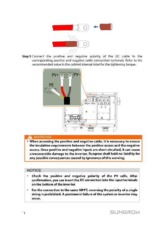
PV+ PV-
PV+ PV- L1 L2 L3
PE
PE
•
•
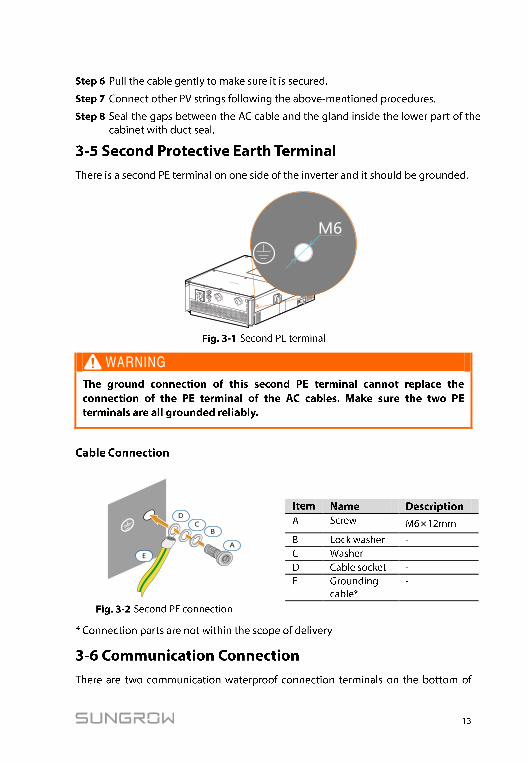
M6
×

Ω
Configuration circuitboardO
FF
ON
120Ω terminating resistor switch
COM1 NC1 NO1COM1
ALARMB2 A2 B2A2
RS485_2A1 B1 A1B1
RS485_1
DIN1 PGND DIN1PGND
LOCAL STOP