Embed Size (px)
Citation preview

lore heat iger@ us at bur ive. leat
tnswe
ei OLO.MOL
288 *Wid mP-a3
d
TER. inc
n attempt to rescue an over- aged, uneconomic ammonia A complex in Severnside, U.K.,
has led to one of the most radical departures in ammonia process tech- nology in more than 20 years. Called the Leading Concept Ammonia (LCA) process, it could shift thinking away from economies of scale - from world-scale ammonia plants of 1,000- 1,500 tons per day capacity to smaller ones of about 500 tons per day. These smaller units, says LCA-developer Imperial Chemical Industries PLC (London), are ton-for-ton as economic to build and efficient to run as the best of the big plants.
projects could be one-third to one- half the size of today’s huge complexes
IC1 revealed the then-unnamed LCA concept in late 1985, but would give few details at the time (Chem. Eng., Nov. 11,1985, p. 19). Now, two new 450-metric tons/d units are up and running at Se-
the future,” says Tom H technology manager. “It po tion: With no penalties, do you wan big ammonia plant or a small one? body knows yet what the answer be.” Officials from the Indian gov ment and the World Bank have seen
CHEMICAL ENGINEERING/JULY
located ammonia plants would seem to most suited.
On the other hand, IC1 believes there could be a need for the more flexible operations of small plants in areas where market growth is no longer the prime factor. For example, the Severn- side complex had what IC1 calls the “least energy-efficient ammonia plants in EuropeJJ-a 300- and a 600-m.tJd unit, both built in the early 1960s. Re- placing the two plants with a modern unit was not the answer since phased turnarounds -rather than one annual one - were needed to keep other parts of the fertilizer complex in operation. But an answer was needed or the com- plex faced shutdown.
An expert solution As a result, seven of ICI’s fertilizer experts met in Edinburgh during a Scot- tish blizzard in the winter of 1984 to come up with a solution. After 14 days, they had worked up the LCA concept. And there is no question that it is radi- cally different: 0 Gone is the huge, multipleburner pri- mary reformer of the conventional am- monia plant - replaced by a gas-heated reformer ,that looks like a small, squat distillation column 0 Gone is two-stage, high-temperature and low-temperature shift conversion - replaced by a single-stage, isothermal shift 0 Gone is conventional carbon dioxide removal - replaced by a pressure-
- IC1 -
swing adsorption (PSA) system that also removes excess nitrogen and re- duces levels of carbon monoxide, meth- ane and inerts. Use of the PSA system also eliminates the purgehydrogen re- covery unit that is a part of conventional ammonia processing to save energy
In the overall LCA process scheme, there is no high-pressure steam system, heat recovery is simplified, and energy wasted during startups and upsets is minimized. IC1 also says there is no nitrogen oxides formation and no hydro- carbon generation at low steam ratios.
Moreover, the firm is ready to show that there is no question about plant economics. The two Severnside units were built for a total cost of about $100 million. “That’s for everything, includ- ing tieing in with the fertilizer complex at the site” says Hicks. “And we believe we can halve that cost for one unit, including utilities.”
In terms of operations, the second Severnside unit, when started up late last year, made ammonia in a world record 19 hours from first introduction of feed gas. The previous record, accord- ing to Hicks, was 43 hours, set in 1985 during the startup of CIL’s ammonia plant in Courtright, Ontario, where ICI’s earlier AMV technology is used (Chem. Eng., July 11,1983, p. 87).
“We are now doing cold restarts a t Severnside in 12 hours and our target is 8 hours,” Hicks says. “We are also do- ing hot restarts in 4 hours and have a control system that enables automatic
developments in catalysts (Chem. Apr. 28, 1986, p. 14).
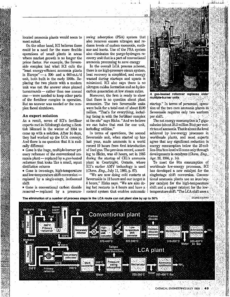
/I// The elimination of a number of process steps in the LCA route can cut plant size by up to 50% 111l1
CHEMICAL ENGINEERING/JULY 1989

copper catalyst, but it is not identical to a low-temperature-shift catalyst,” Hicks says. “Also, catalyst pretreatment is somewhat different because of the lower temperature, but it is not radically different.”
IC1 will not talk about the design and workings of ib small, gas-heated reform er (GHR). But on size alone, it would not have the requirements of the huge, multi- ple-burner reformers of conventional plants, which typically use 20-30 tons of catalyst, making both catalyst and cata- lyst life critical.
In conventional ammonia plant re- formers, IC1 uses calcium aluminate cat- alysts, while alpha aluminate is most favored by U.S. producers. For high- severity reformers, catalyst makers are working towards five-year catalyst life, although three years has been typical. On the other hand, in reformers where condi- tions are less severe, some plants are getting six to seven years of catalyst life. All Hicks will say about LCA catalyst life in general is: “It certainly will not be worse - for one thing, we have milder conditions.”
How it works In the LCA process, natural-gas feed is mixed with recycle hydrogen, heated and desulfurized. Next, it is contacted with hot, circulating process condensate in a saturator, mixed with steam to obtain a steam to carbon ration of about 2.5:1, and preheated in the reformer gas stream.
The gas-heated reformer operates at the steam ratio of 2.51 to minimize heat requirements. The low steam-ratio would give problems with hydrocarbon formation over standard iron-based shift catalysts in conventional plants, where steam ratios of 31 or higher are typical. IC1 says that good temperature control in the LCA shift reactor permits use of a copper-based catalyst, which elimi- nates the possibility of hydrocarbon production.
The gas mixture leaves the gas-heated reformer at about 720°C (roughly 100°C below that of conventional plants) and a pressure of 30-45 bar, and is fed to the secondary reformer for further reform- ing with excess air. The reformed gas, at 970”C, is then cooled by providing heat for the primary, gas-heated reformer and preheat for the reformer gas stream.
“Use of heat from the secondary re- former to drive the primary reformer has escaped people in the past,” says Hicks. “The gas-heated reformer is a sophisti- cated heat exchanger. In the secondary reformer you need to get the tempera- tureup[inorder]toreform the remaining methane with excess air and to get suffi- cient heat to run the gas-heated reform- er. You have to get the heat balance.”
The cooled (260”C), reformed gas then enters the low-temperature shift con- verter - a water-cooled isothermal reac- tor. The shift reaction - carbon monox-
The main gas stream from the pres- sure-swing-adsorption unit is methanat- ed, cooled and dried. I t then enters the ammonia synthesis loop at the circulator suction, is heated and passed over a low- pressure ammonia synthesis catalyst at 80 bars pressure to produce ammonia. “This part of the plant is the same as a conventional ICI AMV process,1t says Hicks.
The hot gas leaving the ammonia con- verter is cooled by generating 60-bar steam and by heating the feed gas to the converter. “This is the only steam raising
Pressure-swing adsorbers take the place of COa-remov- al systems
IC1
ide plus water to form carbon dioxide and hydrogen -is exothermic and requires i drop in temperature to push the reac- tion. As Hicks puts it: “You need the kinetics to drive it quickly enough and the thermodynamics to let it happen, because i s the temperature goes up, the reaction ;lows down. Normally, that means a iigh-temperature shift to what equilibri- Im will allow, then a low-temperature ;hift.”
In doing it with a single shift at con- stant temperature, IC1 uses a cold-water lath in the reactor jacket to remove heat 50 the reaction is not equilibrium limited. ‘If we let it go adiabically, we would lamage the catalyst as the temperature goes up,” Hicks says.
On leaving the converter, the 260°C gas is further cooled by direct contact with circulating process condensate and then fed to, the pressure-swing-adsorption unit for removal of excess nitrogen, car. bon dioxide and inerts. Part of the carbon dioxide from the waste gas of the pres- sure-swing adsorption unit is recovered using an aqueous solution of tertiary amine. This CO, is sold by Severnside as an industrial gas.
ammonia plants into small power sta- tions. In fact, in the LCA concept the core ammonia-making operations are sepa- rated from the utilities area, which con- tains steam and power systems, refri eration and CO, recovery.
IC1 says this speeds design an struction because the core ammonia pro- cess is a standard, repeatable unit inde- pendent of site circumstances utilities area can be tailored to fit circumstances.
The company figures a plant can be ready for startup 24 months after a project has been sanctioned. In fact, construction of the first Severnside plant seems to bear that out. The flowsheet for the plantwas complete din mid 1984. First pilotscale tests were run during the first half of 1985. Site preparation began in the first-quarter of 1986 and much of the plant was completed two years later.
Herb Short (London)
CHEMICAL ENGINEERING/JULY 1989 45