Embed Size (px)
DESCRIPTION
A-8 Student Handout
Citation preview

STUDENT HANDOUT
147 Part 66 Basic Licensing
Subject A-8: Basic Aerodynamics
Copyright © 2007 Aviation Australia
Unit C1a OH&S
All rights reserved. No part of this document may be reproduced, transferred, sold, or otherwise disposed of, without the written permission of Aviation
Australia.
MEAC01B revised 18/04/232 – PPE

This page intentionally left blank

Subject A-8 Basic Aerodynamics
CONTENTS
Page
Definitions 4
Study Resources 5
Introduction 6
Topic 2 – Basic Aerodynamics 9
Topic 3 – Theory of Flight 15
Topic 4 – Stability 19
Topic 5 – Flight Controls 21
Topic 6 – High Speed Flight 27
Issue A – September 2006 Revision 1 Page 4 of 29

Subject A-8 Basic Aerodynamics
DEFINITIONS
Define
To describe the nature or basic qualities of.
To state the precise meaning of (a word or sense of a word).
State
Specify in words or writing.
To set forth in words; declare.
Identify
To establish the identity of.
List
Itemise.
Describe
Represent in words enabling hearer or reader to form an idea of an object or process.
To tell the facts, details, or particulars of something verbally or in writing.
Explain
Make known in detail.
Offer reason for cause and effect.
Issue A – September 2006 Revision 1 Page 5 of 29

Subject A-8 Basic Aerodynamics
STUDY RESOURCES
Jeppesen General
Jeppesen Powerplant
Jeppesen Airframe
Student Handout – Subject 7
Issue A – September 2006 Revision 1 Page 6 of 29

Subject A-8 Basic Aerodynamics
INTRODUCTIONThe purpose of this subject is to familiarise you with basic aerodynamics and the theory of flight. It also covers flight controls and conditions which affect the aerodynamics of aircraft
On completion of the following topics you will be able to:
Topic 1 Atmosphere and Airspeed
State the application of the International Standard Atmosphere (ISA) to aerodynamics.
Topic 2 Basic Aerodynamics
Identify airflow around a body and define the following terms: Boundary layer Laminar and turbulent flow Free stream flow Relative airflow Upwash and downwash Vortices Stagnation
Define the following terms and list their interaction with related forces: camber chord mean aerodynamic chord (MAC) profile (parasite) drag induced drag centre of pressure angle of attack wash in and wash out fineness ratio wing shape and aspect ratio
State the relationship between thrust, weight and aerodynamic resultant.
State how lift and drag are generated and define the following associated terms: Angle of attack Lift coefficient Drag coefficient Polar curve Stall
Identify aerofoil contamination including ice, snow and frost.
Issue A – September 2006 Revision 1 Page 7 of 29

Subject A-8 Basic Aerodynamics
Topic 3 Theory of Flight
State the relationship between lift, weight, thrust and drag.
Define glide ratio.
Identify steady state flight and define performance.
State the theory of the turn.
Define load factor and define its influence on stalling, flight envelope and structural limitations.
List methods of lift augmentation.
Topic 4 Stability
Define the following types of flight stability (active and passive): longitudinal lateral directional
Topic 5 Flight Controls
Define the operation and list the effects of primary control systems:
roll control (ailerons and spoilers)
pitch control (elevators, stabilators, variable incidence stabilisers and canards)
yaw control and rudder limiters
Define flight control using elevons and ruddervators.
Define the operation and list the effects of high lift devices, slots, slats, flaps and flaperons.
Define the operation and list the effects of: Drag inducing devices (spoilers, lift dumpers and speed brakes) Wing fences and saw tooth leading edges
List methods of boundary layer control: Vortex generators Stall wedges Leading edge devices.
Define the operation and list the effects of the following: Trim tabs Balance and antibalance (leading) tabs Servo tabs Spring tabs Mass balance Control surface bias Aerodynamic balance panels
Issue A – September 2006 Revision 1 Page 8 of 29

Subject A-8 Basic Aerodynamics
Topic 6 High Speed Flight
Define the following: Speed of sound Subsonic flight Transonic flight Supersonic flight Mach number Critical mach number Compressibility buffet shock wave aerodynamic heating area rule
State the airflow conditions in engine intakes of high speed aircraft and the factors which affect them.
List the effects of sweepback on critical mach number.
Issue A – September 2006 Revision 1 Page 9 of 29

Subject A-8 Basic Aerodynamics
TOPIC 2 – BASIC AERODYNAMICS
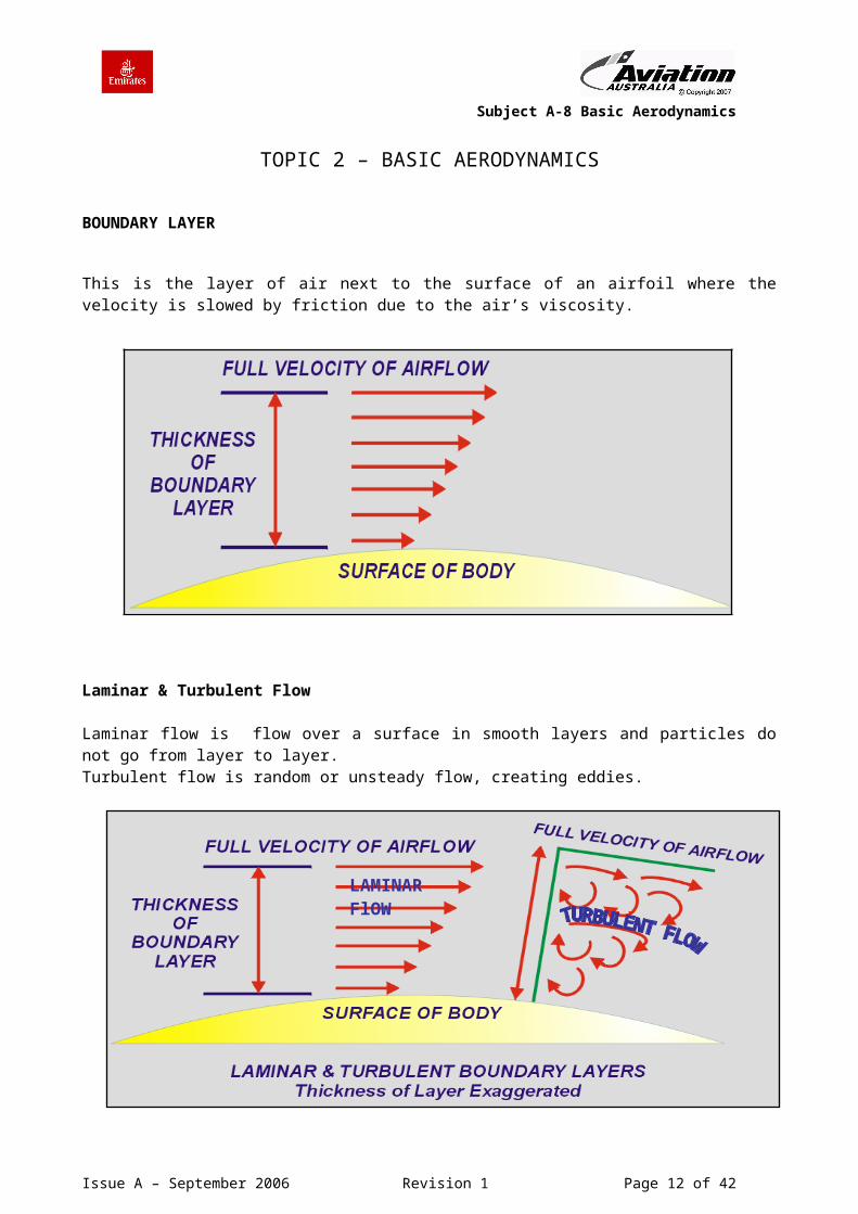
BOUNDARY LAYER
This is the layer of air next to the surface of an airfoil where the velocity is slowed by friction due to the air’s viscosity.
Laminar & Turbulent Flow
Laminar flow is flow over a surface in smooth layers and particles do not go from layer to layer. Turbulent flow is random or unsteady flow, creating eddies.
In turbulent flow, air does not remain in layers and particles go from one layer to another
Issue A – September 2006 Revision 1 Page 10 of 29
LAMINAR FlOW

Subject A-8 Basic Aerodynamics
The attached laminar flow is located at the forward area of the airfoil, and the separated turbulent flow forms at the rear.
Upper and lower layers merge at the trailing edge and form the wake.
STAGNATION POINT
The stagnation point is the first point of contact of relative airflow, or, the point on the leading edge of an airfoil where the airflow divides, some going over the surface and some going below.
The pressure distribution shows how static pressure varies at different points over the wing.
Issue A – September 2006 Revision 1 Page 11 of 29
PRESSURE DISTRIBUTION
Subject A-8 Basic Aerodynamics
PRESSURE & ANGLE OF ATTACK
The angle of attack is between the relative airflow and airfoil chord.
The angle of attack will determine the airfoil centre of pressure (CP).
Increasing the angle of attack moves the CP forwards until the stall when it moves back quickly.
MEAN AERODYNAMIC CHORD MAC
All these wings taper in chord length from root to tip. There will be a mean chord between these two values. One way to define the MAC is to add root chord to tip chord, and divide by 2.
Issue A – September 2006 Revision 1 Page 12 of 29
Subject A-8 Basic Aerodynamics
FINENESS RATIO
The fineness ratio is a measure of the thickness of the airfoil.
WASH IN and WASH OUT
condition of rigging in which a wing has an increase in it’s angle of incidence near the tip is called “wash in.”
With “wash out”, the wing has a decrease in it’s angle of incidence near the tip.
Issue A – September 2006 Revision 1 Page 13 of 29

Subject A-8 Basic Aerodynamics
INDUCED DRAG
This is the part of the total drag which is caused by the same dynamic factors that create lift. Vortices are formed whose strength depend on the angle of attack.
As airspeed increases INDUCED DRAG decreases because the AoA is reduced.
As airspeed increases, Parasite drag, i.e. FORM DRAG and SKIN FRICTION increases.
AIRFOIL ICING
Icing is detrimental to aircraft performance in two ways, changing the aerodynamic shape, and increasing weight
Rime IceIs a milky type ice similar to that which can be found in a domestic freezer. It is formed on leading edges by immediate freezing on contact, of moisture contained within the air. There is no flow of water.
Glaze IceIs a clear and smooth type ice, formed just below freezing.
Issue A – September 2006 Revision 1 Page 14 of 29

Subject A-8 Basic Aerodynamics
This page intentionally left blank
Issue A – September 2006 Revision 1 Page 15 of 29

Subject A-8 Basic Aerodynamics
TOPIC 3 – THEORY OF FLIGHT
CLIMB
In a steady climb, thrust must balance the drag plus a portion of the weight.
So, lift is less than weight Thrust is greater than drag
DESCENT
In a powered descent, thrust may be reduced as gravity supplies some of the energy.
Lift is less than weight. Drag is balanced by the reduced thrust and a part of the weight
Issue A – September 2006 Revision 1 Page 16 of 29

Subject A-8 Basic Aerodynamics
GLIDE
In a glide there is no thrust, and the pilot adopts the descent angle that gives the best Lift to Drag ratio (L/D) and the lowest rate of descent.
Glide Ratio = L/D
= Distance Height
Gravity provides all of the energy to remain flying
LOAD FACTOR
During turning manoeuvres, the weight of the aircraft and centrifugal force combine into a resultant which is greater than aircraft weight alone. This additional load imposed on the aircraft wings thereby increases the stress on the wing, which is also felt by the pilot. This is commonly known as “pulling g”.
LOAD FACTOR = TOTAL LIFT WEIGHT
As angle of bank increases, the total lift to achieve the turn rate required without losing altitude or speed must be increased by the pilot increasing the angle of attack. This will increase the Load Factor, and the aircraft pulls more ‘g’
At 60° of bank the lift is doubled and the load factor is 2. The stall speed also increases.
Issue A – September 2006 Revision 1 Page 17 of 29

Subject A-8 Basic Aerodynamics
CHANGE OF STALL SPEED WITH WEIGHT
With increases in weight there must be compensation.This is achieved by increasing the angle of attack, this increase in angle of attack in turn increases the total lift of the aircraft. The reverse is true also with the loss of weight. Increased weight increases stall speed.
LIMITATIONS
As load factor increases, the stress on the airframe increases. All aircraft will have “g” limits to avoid damage.
It is also possible that a particular aircraft could be designed to reach its Critical Angle and stall before it reaches a dangerous load factor.
Another structural limitation is Gross Weight.There will always be a maximum weight above which the wings cannot provide enough lift for safe flight.
Issue A – September 2006 Revision 1 Page 18 of 29

Subject A-8 Basic Aerodynamics
This page intentionally left blank
Issue A – September 2006 Revision 1 Page 19 of 29

Subject A-8 Basic Aerodynamics
TOPIC 4 – STABILITY
SWEEPBACK
A wing is swept when the leading edge of the wing angles backward or forward from the fuselage.
These planforms allow high speed flight and promote lateral and directional stability.
LATERAL/DIRECTIONAL DYNAMIC STABILITY
Two modes are possible; Dutch Roll and Spiral Instability
Dutch roll is a complex oscillation combining roll and yaw which can be unstable (gets worse)
Spiral Instability is a result of negative static stability in roll and yawThe aircraft continues to roll and yaw after a disturbance and spirals into a dive
A Yaw Damper is an example of an active stability system used to increase the natural (passive) stability, and reduce Dutch roll.
Issue A – September 2006 Revision 1 Page 20 of 29

Subject A-8 Basic Aerodynamics
This page intentionally left blank
Issue A – September 2006 Revision 1 Page 21 of 29

Subject A-8 Basic Aerodynamics
TOPIC 5 – FLIGHT CONTROLS
CONTROL ABOUT TWO AXES - RUDDERVATORS
A combination of rudder and elevator mounted on a Vee tail which provides simultaneous longitudinal and directional control
Also known as a Butterfly tail.
CONTROL ABOUT TWO AXES - ELEVONS
DELTA WINGS
Elevons provide simultaneous control about the lateral axis and the longitudinal axisi.e. pitch and roll.
Issue A – September 2006 Revision 1 Page 22 of 29

Subject A-8 Basic Aerodynamics
AERODYNAMIC BALANCING and TRIMMING
Control forces depend on the airspeed2 and area of surface, The larger and/or faster the aircraft the higher the force required to manoeuvre.
For this reason controls are often balanced to assist the pilots input force during manoeuvres. (Reduce forces)
Trimming however, means removing all control forces during steady flight using a separate control in the cockpit.
AERODYNAMIC BALANCING - HORN BALANCE
A portion of the control surface is extended out ahead of the hinge line. This utilises the airflow about the aircraft to aid in moving the surface.
Although very simple, it does create drag.
Issue A – September 2006 Revision 1 Page 23 of 29

Subject A-8 Basic Aerodynamics
AERODYNAMIC BALANCING - BALANCE PANELS
The hinged balance panel moves inside a sealed space ahead of the aileron.
When the aileron is deflected upward, (as seen above) the air over the bottom surface speeds up and produces a low pressure below the balance panel. (Venturi effect)
This low pressure pulls the balance panel down and puts a force on the leading edge of the aileron in such a direction that it assists the pilot in holding the aileron deflected upward. There is no extra drag.
DRAG INDUCING DEVICES
Spoilers & Lift Dumpers
Spoilers are flight controls that raise up from the upper surface of the wing to destroy, or spoil, lift.
Flight spoilers are used at high speed to decrease lift on one wing and roll the aircraft.
As lift dumpers, they are used to destroy the lift of the aircraft after touchdown to aid in slowing the aircraft
Issue A – September 2006 Revision 1 Page 24 of 29

Subject A-8 Basic Aerodynamics
Speed Brakes
Speed brakes, also called dive brakes,are large drag panels used for airspeed control.
They can also be used to slow anaircraft after touchdown, and reducethe landing roll.
BOUNDARY LAYER CONTROL
Wing Fences
Boundary layer control devices are designed to delay airflow separation over the wing.
Wing fences are fixed vanes that extend chord wise across the wing of swept wing aircraft.
Their purpose is to prevent air from flowing outward along the span of the wing, for this in turn is likely to cause airflow separation near the wing tips and so lead to tip stalling and pitch-up
Issue A – September 2006 Revision 1 Page 25 of 29
WING FENCE

Subject A-8 Basic Aerodynamics
Saw Tooth Leading Edge
Tip separation and stall can also be delayed reduced by introducing a notch or saw tooth in the leading edge.
Each notch generates a strong vortex which controls the boundary layer in the tip region
Vortex Generators
These are small plates or wedges, projecting an inch or so from the top surface of the wing, Each plate generates a vortex adding energy to the boundary layer
The boundary layer travels further along the surface before being slowed up and separating from the wing.
Issue A – September 2006 Revision 1 Page 26 of 29
NOTCH

Subject A-8 Basic Aerodynamics
This page intentionally left blank
Issue A – September 2006 Revision 1 Page 27 of 29
Subject A-8 Basic Aerodynamics
TOPIC 6 – HIGH SPEED FLIGHT
MACH NUMBER
The ratio of the speed of the airplane to the speed of sound in the same atmospheric conditions.
True Airspeed = Flight Mach No. Local Speed of Sound M = 1 is called SONIC flow
High speed flight is measured in terms of Mach Number, which is the ratio of the speed of the aircraft to the speed of sound.When the aircraft is flying at Mach •75 it is flying at 75% of the speed of sound at the ambient air temperature.
The Speed of Sound varies with temperature, and the temp varies with altitude.So aircraft reach Mach 1 earlier at higher altitudes.
CRITICAL MACH NUMBER
The flight Mach number at which there is the first indication of sonic airflow, over the wing.
At Mach 0.5 All airflow over the aircraft wing is less than M =1. As the aircraft accelerates, the Flight Mach No. at which the airflow over the wing, (due to the venturi effect), becomes sonic, is known as the Critical Mach Number.
Issue A – September 2006 Revision 1 Page 28 of 29

Subject A-8 Basic Aerodynamics
SHOCK INDUCED STALL
Beyond Mcrit, the shock wave grows. Airflow through this region undergoes a sudden static pressure increase.
The effect of the sudden pressure rise is to cause the boundary layer to separate from the wing immediately behind the shock, taking with it the layers of air above it, so precipitating a “Shock Stall”.
The shock wave causes earlyairflow separation. (partial stall)
The “Shock Stall “and the ordinary\ stall, although having different causes have certain points in common:-
A sudden increase in drag often accompanied by compressibility buffeting which increases in intensity with growth of stall, and a loss of lift.
SHOCK INDUCED DRAG
The sudden extra drag which is a marked feature of shock stall, is of the same nature as form drag and skin friction.
Overcoming this sudden drag rise gives rise to the expression, “breaking the Sound Barrier”.
Issue A – September 2006 Revision 1 Page 29 of 29