Embed Size (px)
Citation preview

A 50-Kilowatt Broadcast Station Utilizing theDoherty Amplifier and Designed for
Expansion to 500 Kilowatts*W. H. DOHERTY, MEMBER, I.R.E., AND O. W TOWNERt, MEMBER, I.R.E.
Summary Radio station WHAS purchased the first commer-cial transmitter employing the Doherty high-efficiency amplifier andhas installed it in a completely new transmitting plant which is de-signed for expansion to 500 kilowatts output. The transmitter extendsthe use of negative feedback for noise suppression and all vacuum-tube filaments are heated with alternating current, completely elimi-nating rotating equipment except for fans and pumps. Heat for thebuilding is obtained from the water-cooling system, in which por-celain tubes entirely replace rubber hose for the insulating sections.Six-inch concentric transmission line of refined design is used toconvey energyfrom the transmitter to the antenna and for the suppres-sion of harmonics. The novel construction of the feed line to the shunt-excited half-wave antenna makes unnecessary the coupling apparatusordinarily used between the transmission line and the inclined leadto provide the capacitive reactance required at that point in thecircuit.
The theory and practice followed in the design of the high-effi-ciency amplifier and other special features are touched upon as theentire plant is described. Performance data of the transmitter andthe antenna system are also included.
TATION WHAS at Louisville, Kentucky, hasattracted international attention by utilizingthe latest and most improved technical methods
and equipment in its recent installation. The instal-lation is of interest economically as well as technicallybecause this is the first commercial transmitter em-ploying the Doherty high-efficiency amplifier in theUnited States.The new transmitting equipment is located ap-
proximately 18 miles east of Louisville, near East-wood, Kentucky. Situated midway between twocivil airways, this site is far enough from them topermit the erection of a half-wave vertical radiator.It is also sufficiently distant from the densely popu-lated areas to prevent their being subject to highfield intensities if the ultimate capacity of 500 kilo-watts is used. The property has an area of 104 acresand, in addition to the structures required for thetransmitting equipment, there are located on itthe transmitter engineer's house, an artificial lakefrom which the water supply is obtained, and thecaretaker's cottage.The transmitter building was especially designed
to accommodate a Western Electric 500-kilowatttransmitter. The No. 407A-2 transmitting equip-ment which it now houses is sufficient only for thepresent authorized power of 50 kilowatts but is de-signed to drive a 500-kilowatt amplifier and to per-mit this expansion to be made with a minimum ofadded expense.
* Decimal classification: R612.1. Original manuscript receivedby the Institute, August 11, 1938; abridgment received by theInstitute, June 26, 1939. Presented, Thirteenth Annual Conven-tion, New York, N. Y., June 16, 1938.
tBell Telephone Laboratories, Inc., Whippany, N. J.t The Louisville Times Company, Inc., Louisville, Ky.
The small size of the building necessary to housethis equipment is indicative of its over-all economy.Excluding the garage and power platform, it coversan area of approximately 50X68 feet. The front ofthe units of the 50-kilowatt transmitter, shownstippled in the floor plan of Fig. 1, occupy only 17
Fig. 1-First-floor plan.
feet of wall space along one side of the transmittercontrol room, and space is available for those of a500-kilowatt amplifier on the opposite side, as indi-cated by the dotted lines. The corridor around theback of the 500-kilowatt amplifier makes possible theobservation of that unit and the rectifier. Behind the50-kilowatt transmitter is a tube and spare-partsroom, in which there are no exposed voltages, thetransmitter units being completely enclosed. At thefront of the building is an office which is accessiblefrom the entrance and the operating room. The stepsleading to the basement at the rear connect to thepower-platform entrance and an exit.The basement likewise is laid out for future expan-
sion. Two rooms are available for installation of the500-kilowatt amplifier grid-input circuits and theassociated porcelain pipes of the water-cooling sys-tem. In order to co-ordinate the controls, all equip-ment under gas pressure is fed from a nitrogen con-trol room. Underneath the transmitter units is the50-kilowatt filter room where the rectifier-filterequipment and the last-stage water piping are in-
Proceedings of the I.R.E.-September, 1939 531

Proceedings of the I.R.E.
stalled. In one corner of the basement a convenientwork space is available for use in maintenance. Thelayout of the basement and outdoor power platformand cooling platform is shown in Fig. 2, existingapparatus again being shown stippled and futureadditions dotted.
SPACE FORI FILTERINGI EQUIPMENT
ll
Fig. 2-Basement-floor plan.
In the design of the transmitting circuits greatcare was taken to provide the maximum possibleband width for feedback purposes, by including inthe main feedback path only a few stages and by theuse of wide-band interstage coupling circuits. Thefirst audio-frequency stage, for example, as shown onthe block diagram of Fig. 3, is left outside the feed-back loop and is provided with a local feedback of its
AMPLIFIERSRADO-FREQUENCY MODU_
AMPLIFIERS LATING POWER
CRYSTAL HARMONICOSCILLATOR - FILTERI/4wLv1
4MAINAUDIO FREQUENCY 't
AUDIO- AMPLIFIERSFREQUENCY
L__*.- L..___ ______.^FEEDBACK~~~~~RECTIFiER
Fig. 3 Block diagram of amplifier circuits.
own to reduce any distortion and noise arising withinit. The water-cooled stage preceding the final stageis grid-bias-modulated for maximum band width. Asa result of these design considerations, useful feed-back is obtained at modulation frequencies even ashigh as 25 kilocycles. The distortion (Fig. 4), there-fore, is low even at the higher audio frequencies wherethe effective feedback is considerably reduced by thecumulative losses and phase shifts in the variousstages.
The feedback at low frequencies is approximately28 decibels, giving a noise level over 60 decibelsdown with all tubes heated from alternating current.The high-efficiency principle used in the final stage
has been previously explained.' Its operation is basedupon a variable load distribution between the tubes,the carrier output being obtained from one tube
U.3 __ =___-4
a:E e MODULATI :50 100 200 300 500 1000 2000 3000 5000
FREQUENCY IN CYCLES PER SECOND
Fig. 4-Distortion measurements at 50 kilowatts.
alone, while at higher instantaneous outputs the loadis shared by both tubes. The potentials on the tubesin such a circuit are 90 degrees apart in phase. Theessentials of the circuit are shown in Fig. 5. C, andC2 are small variable air condensers for adjusting
ig.5Esenia ls e ig y c
Fig. 5-Essentials of the high-efficiency circuit.
the relative amplitudes and phases of the two gridvoltages. Condenser C3 adjusts the relative phasesof the two plate voltages and C4 tunes the radio-frequency plate voltages of the tubes to the desired180-degree phase relation to the respective gridvoltages. C3 and C4 are high-voltage nitrogen-filledvariable condensers, which lend themselves admir-ably to a compact output circuit arrangement.
Fig. 6-Method of phase indication and tube neutralization.
The circuit adjustment is an extremely simplematter and is accomplished under power using acathode-ray oscillograph. Fig. 6 shows the methodof obtaining indications of the grid and plate voltagesat jacks on the front panel for connection to the os-cillograph. By using reactance potentiometers, con-sisting of high-impedance coils L4 and L6, and low-
1 W. H. Doherty, "A new high efficiency power amplifier formodulated waves," PRoc. I.R.E., vol. 24, pp. 1163-1182; Sep-tember, (1936).
532 September

Doherty and Towner: A 50-Kilowatt Broadcast Station
impedance condensers CB and C6, a fraction of thevoltage suitable for oscillograph deflections and freeof phase shift is obtained across the condensers andconducted to the phase-indicating jacks.
Coil LN in Fig. 6 is employed to neutralize thetube by antiresonating the grid-plate capacitance atthe carrier frequency. This is one of the first methodsever used to neutralize an amplifier.The 50-kilowatt amplifier is operated at an effi-
ciency of 60 per cent, the plate potential being18,000 volts and the plate currents in the two tubesbeing 4.0 and 0.6 amperes, respectively, with nomodulation, and 4.0 and 2.9 amperes when the car-rier is completely modulated by a single tone. Thisrepresents a reduction of nearly one half in the all-day power consumption of the final stage as com-pared with the power required in the conventionaltype of linear power amplifier operating at 33 percent efficiency, and a reduction in plate dissipationto one third of the usual value. At the power rateprevailing at the transmitter location the saving inpower cost made possible through the use of thiscircuit is approximately $6000 a year.The power supply for the transmitting equipment
comes from Louisville over a 66,000-volt transmissionline to the substation at the southeast corner of thetransmitter grounds. A second transmission line isnow being erected to connect the substation throughremotely controlled oil circuit breakers to the DixDam hydroelectric plant, which is about 50 milesfrom the transmitter in the opposite direction fromLouisville. Stepped down at this substation to 12,000volts, the power is fed underground approximately1200 feet to the transmitter building.
In the main switch house are mounted disconnectswitches and oil circuit breakers for the regular andspare cables from the substation, for the 100-kilo-volt-ampere lighting supply transformer, and for thesecond 100-kilovolt-ampere transformer operatingfrom an emergency supply. This emergency powerline comes to the opposite side of the property froma third direction, going underground approximately300 feet to the switch house, and is connected to anautomatic change-over switch so that in the eventof failure of the main power line, there will be nodanger of losing the antenna obstruction lights.
Power for the equipment is carried by cable fromthe main switch house to an oil circuit breaker lo-cated in the transmitter switch house. The circuitthen branches, one part going to the three auxiliarytransformers which step the voltage down to 460volts for distribution in the transmitter, while theother branch connects to the high-voltage trans-formers through a second oil circuit breaker, whichis electrically tripped and reclosed from the transmit-ter control panel. Only two plate transformers, op-erating in open delta, are used. They are rated at382 kilovolt-amperes each, which is greater than re-
quired for 50-kilowatt operation, but with the addi-tion of a third transformer they provide sufficientcapacity to supply the requirements of a 500-kilo-watt amplifier. At the end of the plate-transformerline-up, provision is made for this third unit. Thesecondaries of the plate transformers connect throughan automatic voltage regulator to the high-voltagerectifier. All connections are made by means ofcable, thus making possible a very clean-cut andaccessible power platform.On the inside of the building, immediately adja-
cent to the power platform, is the 500-kilowattamplifier room. Here the terminating-end seals of the500- and 50-kilowatt transmission lines are now con-nected together. These are so placed in order to pro-vide for switching facilities which will permit the 50-kilowatt transmitter to operate either directly intothe antenna, as at present, or to drive the 500-kilo-watt amplifier with its output connected to theantenna. Also in this room is the high-voltage recti-fier which supplies 18,000 volts to the water-cooledtubes of the transmitter. It uses Western Electric255B mercury-vapor rectifier tubes for supplying the50-kilowatt equipment and is capable of rectifyingthe output required for a high-efficiency 500-kilowattamplifier by a change of tubes only. An extra rectifiertube is kept heated for quick replacement in case ofa tube failure.
In the pump room, two tanks and two pumps areinstalled, one of each being a spare. The output mani-fold of the pumps is equipped with a thermometer,pressure gauges, and position indicators on thethrottle valves. The cooling-water pipes go throughthe boiler room to the two water-cooled stages of thetransmitter. The return lines terminate at a Venturimanifold, where the rate of flow of the water ismeasured in each branch and the necessary relaysinserted to interlock with those of the plate and fila-ment circuits. The water from the two return lines isthen combined and can be routed into the outdoorcooling units or, in cold weather, into units providedin the "boiler room" for heating the building. Noother source of heat is required for this purpose.The filter for the rectifier supplying both water-
cooled stages of the 50-kilowatt transmitter is lo-cated in a basement room, immediately under thetransmitter units, and consists of a 12-microfaradcondenser bank and a 5-henry choke coil. Were itnot for the large amount of feedback employed inthe transmitter, a considerably larger filter condenserwould be required to prevent distortion at very lowmodulation frequencies. The coil is shunted by aThyrite protector whose inverse voltage-resistancecharacteristic effectively prevents excessive surge po-tentials. A charging resistance in series with the filtercondensers to limit the starting surge current isautomatically short-circuited after a brief period.On the ceiling of this room, immediately below the
1939 533
Proceedings of the I.R.E.
two 100-kilowatt vacuum tubes of the power ampli-fier, are mounted straight porcelain tubes which con-vey the distilled water to the anodes. The water forthe modulating-amplifier stage is supplied throughcopper pipes, the insulating porcelain tubes for thisstage being incorporated within the amplifier unititself.A small room in the basement is provided exclu-
sively for the nitrogen-gas regulators and manifoldsfor maintaining a 45-pound pressure on the radio-
Fig. 7-Interior of coupling house showingtransmission-line end seals.
frequency transmission lines and 175 pounds on thetwo variable condensers of the 50-kilowatt amplifier.As the entire plot was underlined with limestone
at an average depth of from one to two feet, it wasnecessary to construct the 6-inch transmission lineabove the ground. The expansion of the line duringthe seasons and throughout the day requires a sup-port utilizing rollers to permit this movement. Bymeans of specially designed insulators supporting theinner conductor it has been possible to construct theline so that the breakdown voltage is not appreciablydecreased by the presence of the insulators.Two harmonic shunt lines are connected in parallel
with the transmission line at the coupling house andconnection is made from them through a meter tothe antenna feed line. One is a quarter-wave shuntshort-circuited at the far end for even-harmonic sup-pression. The second is a twelfth-wavelength shunt,open at the far end, used for third-harmonic suppres-sion. The only other apparatus required in thecoupling house is a coil which parallel resonates withthe capacitance of this third-harmonic shunt. Fig. 7is a view of the interior of the coupling house.
In order to provide the capacitance required totune the shunt-excited antenna in a form whichwould withstand the voltage developed by the trans-mission of 500 kilowatts, a four-conductor feed linewas designed by the Bell Telephone Laboratories.The two outside conductors connect to the transmis-sion line and the two inner ones connect to the tower.They are constructed of one-inch copper tubes andthe distributed capacitance between them is usedto provide a capacitive reactance equal to the in-ductance reflected by the feed line. The two innerconductors have a flexible joint at the spreader sothat the point at which they tap into the tower maybe more easily adjusted to terminate the transmis-sion line.
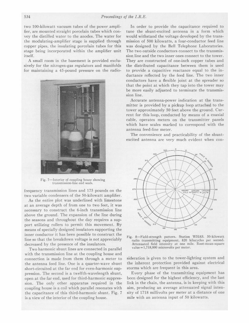
Accurate antenna-power indication at the trans-mitter is provided by a pickup loop attached to thetower approximately 50 feet above the ground. Cur-rent for this loop, conducted by means of a coaxialcable, operates meters on the transmitter panelswhich have scales marked to correspond with theantenna feed-line meter.The convenience and practicability of the shunt-
excited antenna are very much evident when con-
Fig. 8-Field-strength pattern. Station WHAS. 50-kilowattradio transmitting equipment. 820 kilocycles per second.Attenuated field intensity at one mile. Root-mean-squarevalue = 1,718,000 microvolts per meter.
sideration is given to the tower-lighting system andthe inherent protection provided against electricalstorms which are frequent in this area.
Every phase of the transmitting equipment hasbeen designed for the highest efficiency, and the lastlink in the chain, the antenna, is in keeping with thisaim, producing an average attenuated signal inten-sity of 1718 millivolts per meter at a distance of onemile with an antenna input of 50 kilowatts.
534