Embed Size (px)
Citation preview

"Hawthorne Bay"A 47' Bayliner Pilothouse Motoryacht
Operating Manual
Edition of April 10, 2009Copyrighted. See notice next page.
Section Contents
1 Introduction & General Boat Description
2 Specifications, Capacities, & Important Numbers
3 Operating Checklists & Maneuvering Suggestions
4 Specific Discussion of Boat Systems
5 "What to Do" for each Boat System Concern
6 EMERGENCY PROCEDURES
7 Index
8 Instruction Manual: "Maneuvering Inboard Engine Power Boats"
San Juan Yachting (360) 671-4300 (800) 677-7245 Fax (360) 671-43012615 South Harbor Loop Suite 1, Bellingham WA 982225
E-mail: [email protected]

(Intentionally left blank)

1 - 1 Introduction to the Manual
Section I: Introduction & General Boat Description
About this ManualManual Objective and Limitations
This manual is intended to introduce you to "Hawthorne Bay", its systems and features,allowing you to operate it with the confidence and self-assurance necessary to enjoy yourcruising vacation to its fullest. It is not intended to replace a good basic understanding ofseamanship, including navigation skills, weather interpretation or boat handling. You areexpected to have an understanding of these subjects obtained through other sources,including training, seminars, reading and perhaps most important, experience.
There is no way that a small manual like this one can answer every question or give youa solution to every circumstance, foreseen or unforeseen. If you have a question which limitsyour understanding or handling of this vessel, ask your SJY checkout skipper or contact theoffice for details (you might make a list of questions as you read the manual, saving them allup to ask efficiently at one time).
How the Manual is OrganizedThe tab for each section defines its general purpose as shown on the front page.You will use the Section 3, containing checklists, most of all. You should have it
available so that each checklist can be used on a daily basis, even after you are familiar withthe boat.
Section 5, regarding Emergency Procedures, is the most important, and you shouldread it, but hopefully you will never need it.
Read this Section I first to learn about this manual and the general details of your boat. The other sections will tell you most of what you need to know to enjoy your cruise to
the fullest with safety and confidence.
Manual Copyright 2007, 2008 Joseph D. Coons.This manual was written for this boat's owner and San Juan Yachting, Bellingham
Washington U.S.A. by Joseph D. Coons, 1220 Birch Falls Drive, Bellingham, WA 98229, Telephone (360) 647-0288. All rights reserved.
This manual may not be quoted, copied, or duplicated, in whole or in part, in printedor electronic form, without express written consent from the author.
1 - 2 General Description of the Vessel
General Description of this Bayliner 47' YachtExterior
Hawthorne Bay, a Bayliner 47' "4788Pilothouse Motoryacht" is a modern vesselthat has many of the amenities of amegayacht, with a fiberglass hull, cabin,deck and flybridge, a fiberglass swim step,and stainless steel welded fittings andhandrails. The window frames are aluminumwith sliding glass panes, and the boat hasBowmar hatches for light and/or ventilation.
Of note are the walk-around forwarddeck and accessible side decks, which inspite of the wide salon dimensions, stillenable reasonably safe, secure passageabout the boat by passengers (forward) andcrew (alongside the salon).
Abreast of the forward salon windowsare the port and starboard fuel fills, and onthe port side of the forward deck, the twowater fills. The holding tank pumpout deckplate is on the starboard side by the salonwindows; the shore power connections arealso here just above the starboard side deckjust aft of the pilothouse door. (Theseconnections are selected by the shore power switch in theelectric panel; note that when this cable is to bedisconnected, the master breaker in the AC panel shouldfirst be turned to the "off" position to avoid arcing whichcould damage the plug contacts.)
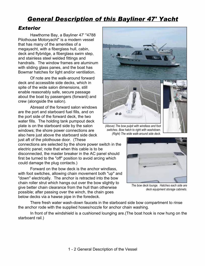
Forward on the bow deck is the anchor windlass,with foot switches, allowing chain movement both "up" and"down" electrically. The anchor is retracted into the bowchain roller strut which hangs out over the bow slightly togive better chain clearance from the hull than otherwisepossible; after passing over the winch, the chain goesbelow decks via a hawse pipe in the foredeck.
There fresh water wash-down faucets in the starboard side bow compartment to rinsethe anchor rode with the supplied hoses/nozzle for anchor chain washing.
In front of the windshield is a cushioned lounging are.(The boat hook is now hung on thestarboard rail.)
(Above) The bow pulpit with windlass and footswitches. Bow hatch to right with washdown.
(Right) The wide walk-around side deck.
The bow deck lounge. Hatches each side aredeck equipment storage cabinets.

1 - 3 General Description of the Vessel
The cockpit (with storage lazarette beneathaccessed by three floor hatches for access) is especiallyuseful for handling the dinghy after it is launched from theboat deck. It has side storage compartments and both ahot/cold fresh water swim shower fixture and a fresh waterhose bib.
In this lazarette beneath the cockpit are a numberof items. The boat's two 30-amp shore power cables are25 and 50 feet long and stay with the boat when awayfrom its home dock. (See section 4.) The lazarettehatches also allow access to the ship's genset andseveral batteries in case maintenance is required.
A practical ladder leads from the cockpit to the boatdeck to ease dinghy handling (although when the dinghy isstowed on its davits the crew will use the stairs from thepilothouse to the flybridge as the flybridge access, as thedinghy nearly fills the boat deck space.) The boat deckstores the yacht's dinghy, the barbecue, and the galley’spropane tanks and valves. With its limited railings, thisarea will not normally be used by crew when at sea exceptfor launching the tender, which is launched with a deckcrane the remote control for which is stowed under the aftseat in the L-settee on the port side of the flybridge. The12' Dinghy is equipped with an electric start/tilt outboard,with nav lights and electric bilge pump.
The cockpit to starboard. Note the ladder to theboat deck and (with the black door) one of the
two cockpit cabinets.
Starboard cockpit hatch to the lazarette opened.
On the boat deck. The dinghy aft includes a40hp Honda outboard.
The dinghy bow includes a console and bilgepump and light switches and gauges. The blackpanel is a wintertime solar charger for the dinghy
battery.
The barbecue, with its propane tank aft.
The galley propane tanks aremounted on the aft side of
the flybridge settee
1 - 4 General Description of the Vessel
F/B Door Clip.
One of the retractable cleatsin the “up” position.
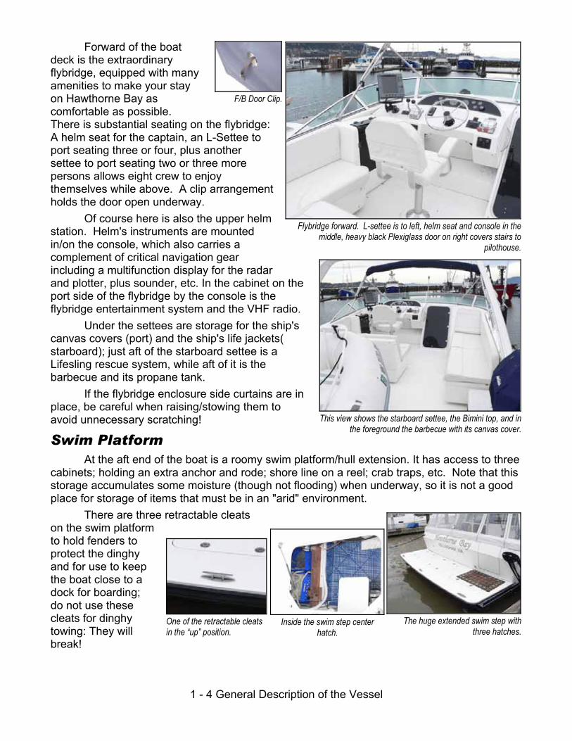
Forward of the boatdeck is the extraordinaryflybridge, equipped with manyamenities to make your stayon Hawthorne Bay ascomfortable as possible.There is substantial seating on the flybridge:A helm seat for the captain, an L-Settee toport seating three or four, plus anothersettee to port seating two or three morepersons allows eight crew to enjoythemselves while above. A clip arrangementholds the door open underway.
Of course here is also the upper helmstation. Helm's instruments are mountedin/on the console, which also carries acomplement of critical navigation gearincluding a multifunction display for the radarand plotter, plus sounder, etc. In the cabinet on theport side of the flybridge by the console is theflybridge entertainment system and the VHF radio.
Under the settees are storage for the ship'scanvas covers (port) and the ship's life jackets(starboard); just aft of the starboard settee is aLifesling rescue system, while aft of it is thebarbecue and its propane tank.
If the flybridge enclosure side curtains are inplace, be careful when raising/stowing them toavoid unnecessary scratching!
Swim PlatformAt the aft end of the boat is a roomy swim platform/hull extension. It has access to three
cabinets; holding an extra anchor and rode; shore line on a reel; crab traps, etc. Note that thisstorage accumulates some moisture (though not flooding) when underway, so it is not a goodplace for storage of items that must be in an "arid" environment.
There are three retractable cleatson the swim platformto hold fenders toprotect the dinghyand for use to keepthe boat close to adock for boarding;do not use thesecleats for dinghytowing: They willbreak!
Flybridge forward. L-settee is to left, helm seat and console in themiddle, heavy black Plexiglass door on right covers stairs to
pilothouse.
This view shows the starboard settee, the Bimini top, and inthe foreground the barbecue with its canvas cover.
The huge extended swim step withthree hatches.
Inside the swim step centerhatch.

1 - 5 General Description of the Vessel
Battery switches...
Interior Accommodations
Main DeckThe boat is entered by the main sliding door aft, or by the less-used entry direct thru a
pilothouse port side door. The pilothouse door is fitted with a strong lock. Be careful to closethe door when underway in heavier weather to avoid getting spray in the boat.
Be sure to close the door when starting engines to keep exhaustfumes out until the engines warm up!
Forward of the aft sliding door to starboard is, an “L” settee with storage beneath, andforward of that the refreshment bar with wet sink and an icemaker just forward of it; and thenon the forward bulkhead the entertainment equipment including AM/FM/Stereo with CD andDVD players. A high-low cocktail table is in front of the settee; its leaves open up for dining.
Across from this settee to port are twocaptain's chairs and a side table to provide a very nicegathering spot after a day's cruising. Behind the aftchair is a cabinet with the ship’s main batteryswitches.
Looking aft from inside the salon toward the cockpit. The slidingentry door is by the easy chair. The battery switch cabinet shownbelow is behind the easy chair by the door.
A salon view looking forward to starboard from the doorway....
Some of the L-Settee’s storage.
1 - 6 General Description of the Vessel
This is the pilothouse helm console and helm seat, with a terrificarray of instruments all in easy reach...
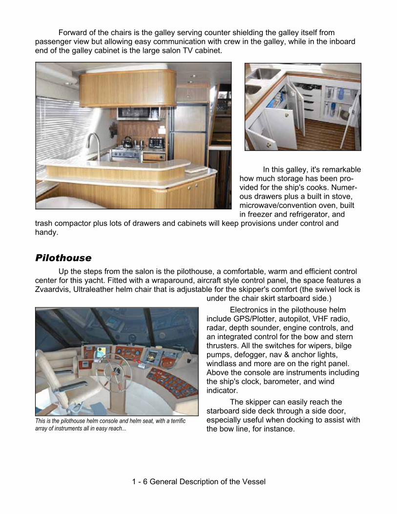
Forward of the chairs is the galley serving counter shielding the galley itself frompassenger view but allowing easy communication with crew in the galley, while in the inboardend of the galley cabinet is the large salon TV cabinet.
In this galley, it's remarkablehow much storage has been pro-vided for the ship's cooks. Numer-ous drawers plus a built in stove,microwave/convention oven, builtin freezer and refrigerator, and
trash compactor plus lots of drawers and cabinets will keep provisions under control andhandy.
PilothouseUp the steps from the salon is the pilothouse, a comfortable, warm and efficient control
center for this yacht. Fitted with a wraparound, aircraft style control panel, the space features aZvaardvis, Ultraleather helm chair that is adjustable for the skipper's comfort (the swivel lock is
under the chair skirt starboard side.) Electronics in the pilothouse helm
include GPS/Plotter, autopilot, VHF radio,radar, depth sounder, engine controls, andan integrated control for the bow and sternthrusters. All the switches for wipers, bilgepumps, defogger, nav & anchor lights,windlass and more are on the right panel. Above the console are instruments includingthe ship's clock, barometer, and windindicator.
The skipper can easily reach thestarboard side deck through a side door,especially useful when docking to assist withthe bow line, for instance.
1 - 7 General Description of the Vessel
...and this is the pilothouse port & aft view! Note the port side door inthe back of the picture: The removable cushions are in place. Over
the settee the cabinet holds manuals and other literature.
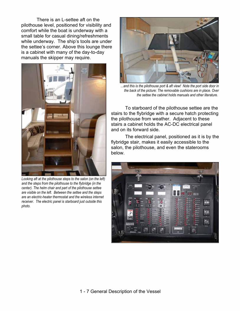
Looking aft at the pilothouse steps to the salon (on the left)and the steps from the pilothouse to the flybridge (in thecenter). The helm chair and part of the pilothouse setteeare visible on the left. Between the settee and the stepsare an electric-heater thermostat and the wireless internetreceiver. The electric panel is starboard just outside thisphoto.
There is an L-settee aft on thepilothouse level, positioned for visibility andcomfort while the boat is underway with asmall table for casual dining/refreshmentswhile underway. The ship’s tools are underthe settee’s corner. Above this lounge thereis a cabinet with many of the day-to-daymanuals the skipper may require.
To starboard of the pilothouse settee are thestairs to the flybridge with a secure hatch protectingthe pilothouse from weather. Adjacent to thesestairs a cabinet holds the AC-DC electrical paneland on its forward side.
The electrical panel, positioned as it is by theflybridge stair, makes it easily accessible to thesalon, the pilothouse, and even the stateroomsbelow.

1 - 8 General Description of the Vessel
The #2 (Bunk) Stateroom. Behind themirrored door are copious drawers anda hanging locker.
(Above) A guest headcabinet. (Right) A portion ofthe guest head.
One of the two equipmentaccess cabinets in thecompanionway.
The #1 Guest S/R. To left of the dooris the hanging locker, to right a bedtable, and below the berth, drawers.
Stateroom Deck
Access to the lowerdeck is via the steps fromthe salon by the galley. Atthe foot of the steps tostarboard are two cabinetdoors opening into theutility area of the boatwhere head pumps andsimilar equipment islocated. Past the first ofthese is the guest headcompartment door; the head has vanity, toilet, stall
shower and severalstorage cabinets.
To port of the companionway a doorway leads into the #1 gueststateroom with a double berth,hanging locker and drawers.
Further down thecompanionway to port is the ship'swasher-dryer behind cabinet doors;then the door to the #2 (Bunk)stateroom. A door from thisstateroom allows access to themaster stateroom so that if only fourare aboard, the occupants of themaster can use this smallerstateroom as a convenient andflexible storage or dressing area.

1 - 9 General Description of the Vessel
A portion of the M/S/R head compartment. The boat has Vacu-Flush toilets in bothcompartments.
Another M/S/R head view.
The Master Stateroom under-berth drawers. This boat has lots of storage!
One of the M/S/R hanging lockers. This oneis to starboard.
The forward master stateroom features anisland-queen berth with plenty of storage in hanginglockers, drawers and cabinets. It has its own head,accessed by a door aft to starboard.
The Master Stateroom aboard HawthorneBay is sumptuous! It features a queen-size islanddouble berth (the best arrangement for quiet nightsat anchor) with hanging lockers on each side, plusdrawers and cabinets on each side and under theberth’s aft (foot) end. As is true throughout thevessel, lighting is excellent and well-placed.
A separate master stateroom head is accessed through a door on the starboard aft sideof the stateroom. This head also has a stall shower/bathtub and lots of storage.
The boat also has a central vacuum system located inthe companionway access panel to starboard of thecompanionway. Its hose is stowed in the #1 gueststateroom, and its power is controlled by a breaker in the ACbreaker panel in the pilothouse.

1 - 10 General Description of the Vessel
(Above) To starboard in the forwardengine room compartment.
(Below) To port are filters and controls(green) for the watermaker and (red)
water pump.
Looking aft through the utility compartment at the engineroom. The Cummins engines are to each side, while theWesterbeke generator sound shield cabinet is all the wayaft; right in front of the Westerbeke cabinet you can see thesea water hoses for the engines leading to the seacocks.
Under the port cockpit hatch is the lazarette withthe Webasto Diesel furnace, the port enginemuffler, and a (grey) battery box. The Westerbeke generator under the middle cockpit hatch,
with associated equipment and the stern thruster masterswitch. The folding chairs are atop the genset cabinet.
Engine Room:Access to the engine room area of the vessel is through
the hatch at the top of the lower stateroom companionway steps. Engine Room lighting is turned on before entering by a
breaker in the ship's DC power panel at the top of thesalon-pilothouse steps.
The engine area is divided into two compartments. Theforward one of these (where the hatch is), a utility compartment,contains the bow and stern thruster batteries; the water heater;and filters for the watermaker plus other miscellaneous items.
The engineroom layout isconventional: Oildipsticks and fillersare inboard forwardon each engine. Thecoolant expansiontanks are just aft ofeach engine (the onefor the port engine isoutboard of the port engine’s transmission). Aft ofthe engines are the “Everhot” hot water tank heatedby the Diesel Furnace (to port); the transmissionsand shaft seals; and the sea water strainers and,nearly on the centerline, the thru-hulls andseacocks.The good news is that except for the engines
themselves, nothing is outboard of the engines!
Lazarette: Under the lazarette hatches are the Westerbeke Generator; the ship’sbatteries; two folding deck/dock chairs; the Diesel Furnace; and some miscellaneousequipment.
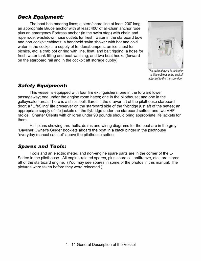
1 - 11 General Description of the Vessel
The swim shower is tucked ina little cabinet in the cockpit
adjacent to the transom door.
Deck Equipment:The boat has mooring lines; a stern/shore line at least 200' long;
an appropriate Bruce anchor with at least 400' of all-chain anchor rodeplus an emergency Fortress anchor (in the swim step) with chain andrope rode; washdown hose outlets for fresh water in the starboard bowand port cockpit cabinets; a handheld swim shower with hot and coldwater in the cockpit; a supply of fenders/bumpers; an ice chest forpicnics, etc; a crab pot or ring with line, float, and bait rigging; a hose forfresh water tank filling and boat washing; and two boat hooks (forwardon the starboard rail and in the cockpit aft storage cubby).
Safety Equipment:This vessel is equipped with four fire extinguishers, one in the forward lower
passageway; one under the engine room hatch; one in the pilothouse; and one in thegalley/salon area. There is a ship's bell; flares in the drawer aft of the pilothouse starboarddoor; a "LifeSling" life preserver on the starboard side of the flybridge just aft of the settee; anappropriate supply of life jackets on the flybridge under the starboard settee; and two VHFradios. Charter Clients with children under 90 pounds should bring appropriate life jackets forthem.
Hull plans showing thru-hulls, drains and wiring diagrams for the boat are in the grey "Bayliner Owner's Guide" booklets aboard the boat in a black binder in the pilothouse“everyday manual cabinet” above the pilothouse settee.
Spares and Tools:Tools and an electric meter, and non-engine spare parts are in the corner of the L-
Settee in the pilothouse. All engine-related spares, plus spare oil, antifreeze, etc., are storedaft of the starboard engine. (You may see spares in some of the photos in this manual: Thepictures were taken before they were relocated.)

1 - 12 General Description of the Vessel
(Intentionally left blank)

2 - 1 Specifications and Capacities
Section 2: Specifications,
Capacities, & Important NumbersImportant Data For This Boat
Vessel Name: Hawthorne BayVessel Official Number: 1122643Vessel Registration Number: N/AHull ID Number BLBA508VB101Capacities:
Sleeps six: Two in each stateroom (recommended)Sleeps eight: Two in each Stateroom plus Two on the SetteesFuel: 444 Gallons in two 222 gallon tanksFresh water: 160 Gallons in one tank and a water bladder tankHolding Tank: 48 Gallons in one tank
Dimensions:Length: 47 Feet 4 Inches plus swim platform extension (54' LOA)Beam: 14 Feet 11InchesDraft: 3 Feet 4 InchesDisplacement: 30,000 Pounds
Fluids:Motor Fuel: #2 DieselMotor Oil, mains: 15W-40 Chevron Delo MultigradeTransmission Oil: 30W Chevron Delo Single GradeEngine Coolant: 50-50 mix, ethylene glycol and water; corrosion inhibitor
addedOperating Parameters: (2250 RPM Recommended Maximum Cruising Speed!)
RPM SpeedGPH Total Both
Engines Combined Naut. Miles/Gallon
1600 9.0 8.0 1.125
1800 12.0 11.0 .916
2000 14.0* 16 .875
2200 18.5* 22.0 .840
2400 22.0* 30.0 .733
All figures are estimated and may vary.*Planing figures presume boat is placed "onplane". See discussion page 4.3.

2 - 2 Specifications and Capacities
(Intentionally left Blank)

3 - 1 Checklists
Section 3: Checklists & ManeuveringSuggestions
Operating Checklists - Hawthorne BayFirst Thing Each Day:
G Check engine oil, coolant.G Check under-engine oil pads. Okay?G Check fuel tank levels.G Check holding tank. Need pumping?G Turn off anchor light if illuminated.
Starting Engines:G All lines clear of propellers and on deck.G Items running on AC evaluated vis-a-vis the Inverter and generator.G Start Engines:
G Throttles at “idle” and shifts in “Neutral”G Turn engine key past "on" to engage starter
Leaving Dock: (Only 3-4 minute engine warmup required!]G Shore power breaker "off", cord removed, and stowed on board.G Lines removed as appropriate.G Fenders hauled aboard and stowed.G Lines and other deck gear secure/stowed.G Doors and hatches closed and secured as appropriate.
Underway:G Helms person on watch at all times.G RPM under 1400 until engines warm to 1400; RPM (Recc. Max cruise 2250 RPM).G Wake effects always in mind.
Approaching Dock:G Fenders out on appropriate side. G Trim Tabs "Up" (Bow Up)G Bow line OUTSIDE stanchions and bloused around to midships.G Engines dead slow, wheel centered for engine-only maneuvering.G Mate ready to secure stern first (in most circumstances).

3 - 2 Checklists
At Dock in Marina:G Lines secure, including spring lines.G Trim Tabs "Up" (Bow Up)G Step stool out, if needed.G Water heater breaker off until Inverter current settles (see "Inverters" below).G Shore power cord connected.G Shore power switch "On" to appropriate shore power location.G Shore power confirmed on meters.G Inverter "On".G Electric use monitored for current capacity of shore facilities.
Mooring at Buoy:G Skipper puts starboard side gate next to buoy with mate standing by it.G Mate loops 20' or so line, such as bow line, through buoy ring.G Mate holds two ends together, walks up side of boat to bow of boat.G With buoy held close to bow, line secured to each bow cleat through hawsepipe.G Inverter "Off" unless in use or Generator is running.
Mooring at Anchor:G Anchor is lowered from pulpit while boat is backed up slowly away from anchor.G When desired chain length out (4:1 or 5:1 scope), windlass is stopped.G Engines reversed "for count of five" until chain pulls up virtually straight. Note: the
boat is not held in reverse against a taught anchor chain!G Inverter "Off" unless in use or generator is running.
Overnight Checklist in Marina:G Shore power "On".G Trim Tabs "Up" (Bow Up)G Inverter "On".
Overnight at Anchor or Buoy:G Inverter "Off" to conserve batteries.G Trim Tabs "Up" (Bow Up)G Anchor light "On".G DC electrical items all "Off" including radios, extra lights, etc.
Upon Arising:G If at anchor or buoy, Inverter "On" only if necessary.G If necessary, run generator to charge batteries if at anchor or buoy.G Inverter "On" if shore power available or generator is running.G Turn on heat if necessary.G Go to top of this Hawthorne Bay checklist.

3 - 3 Maneuvering Suggestions
Maneuvering SuggestionsDocking & Undocking
Usually it's easier to dock bow in. Have your mate at the side rail opening, ready to stepoff and secure the stern line, against which you can pull to swing the bow in toward the dock. By having your mate ready to disembark when close to the dock, he/she will not have to jumpto the dock, risking a turned ankle or falling overboard. It is the skipper's job to put the boatnext to the dock so the mate needn't jump, but merely step off!
When approaching a dock, have the fenders out as required and have the bow linealready rigged, passed through its hawse pipe, and draped back on the side of the boatbetween the stanchions so it can be reached from the dock. Never put a line from a cleat overa rail: the boat's weight will bend or break the rail if it pulls against the line! Then, when themate is ashore, the line can easily be reached . . .
If dock clearance permits, spring the boat forward so that it pulls forward on the sternline. This will bring the stern close to the dock. Let the bow line out enough so that the boatcan rest against the stern and midships fenders.
Maneuvering in a HarborWith its twin screws, you'll do best if you center the rudder and steer with the engines
only! The props are so large that the boat will respond well (except in high winds) just with useof the propellers in forward and/or reverse. Take your time, and keep the boat running "deadslow" so that you can plan each approach. You shouldn't need to use the throttles at all.
Filling The Fuel TanksWith the large fuel tanks, you can fuel the boat pretty fast at the boat's side deck fill
fittings using a standard hose and nozzle (like the ones on auto gas pumps). You need to fueleach tank separately. Fill both the tanks completely but do not spill fuel!
You can control the flow rate by sound, as the fill pipes make the characteristic"getting-to-the-top-of-the-bottle" pitch change when the fill pipes begin to fill when the tanksthemselves are full but be careful: It's a fairly long run to the tanks from the fill pipes! (The tankvents will gurgle before the tanks are full, so when the vents begin gurgling, slow down untilyou hear the fill pipes' pitch change.)
AnchoringAnchoring can be accomplished safely with a minimum of fuss if you are prepared. Or,
if you are not ready, it can be stressful and dangerous for you or the boat.Before attempting to anchor, select an anchorage with a soft bottom such as sand, mud,
or gravel, if possible. Look at the charts and cruising guides for tips on good locations. Then,choose the spot in the anchorage where you have room to "swing" on the anchor withoutdisturbing other boats. Remember, responsibility for leaving room goes to each successiveboat to arrive, for the first boat has priority in the anchorage!
Here in the Northwest, because of the deep waters, all-chain rodes and small bays, weanchor a little differently than in the Gulf of Mexico or Carribean, for example. First, except insevere weather we use anchor chain scopes of only 4-to-1 or 5-to-1. For example, in waterthat is 40 feet at high tide in the typical anchorage, we might use 160 feet of chain unless theweather was to be gale force or greater winds.

3 - 4 Maneuvering Suggestions
Second, because of the small bays and steep bottoms, we often rig a shore line fromthe stern of the boat to shore. The best example of this would be at Todd Inlet at ButchartGardens. Here is a bay that can accommodate 8 - 10 boats, yet it is only about 150' wide and200' long! Boats attach their bows to the mooring buoys or, in a few cases, anchor; and thentheir sterns are secured to rings provided in the steep cliffs overlooking the bay. Boats arethus perhaps only 15-20' apart, side to side.
Third, boats often will "raft" side by side in busy marinas, although this is not toocommon.
Fourth, courteous boaters will call vessels coming into busy bays and offer to let themraft to the same buoy, if signs on the buoys do not limit usage to only one boat dependingupon length.
Anchoring safely requires two persons, one at the helm maneuvering the boat and oneon the bow operating the anchor. Putting the bow of the boat over the spot where the anchor isto be placed after checking the depth on the depth sounder, the windlass foot-switches areused to lower the anchor slowly toward (but not onto) the bottom, by watching the chainmarkings.
When the anchor is about to reach bottom, the boat is backed away by putting theengines into reverse for 5 seconds: Eddies from the chain indicate motion. Resume loweringthe anchor while drifting backwards (watch the eddies and add another burst or reverse ifnecessary!) until the desired amount of chain is out. Stop paying out chain. Engage reversefor five seconds at a time until the chain starts to pull straight off the bow toward the anchor. Astraight chain indicates a "set" anchor!
NEVER pull on the chain for more than five seconds, and never at any engine RPMother than idle! Putting the boat's weight plus its horsepower on the chain forcefully even atidle will bend the anchor and/or damage the mooring gear!
If while checking the set, the chain rumbles and clunks, and seems to release in bursts,it means you're anchoring on a rocky bottom and the anchor is not holding. Be patient: It maynot set on the first try, and you'll have to repeat the process sometimes to get a good "bight"on the bottom.
Shore LinesWhen a shore line is required, anchors are set 75 - 100 feet from shore, with the boat
backing toward shore during anchor-setting. The stern line is put around a tree, and broughtback to the boat.
During this process, be sure to keep clear of rocks near the shore, and allow for ourNorthwest tides, occasionally twelve feet, and sometimes 20 feet when further north! Checkthe present tide, and high and low tides before beginning anchoring: No sense anchoring in 15feet of water if you're at the "top" of a 15 foot tide!
To get to the shore, you will need to have a dinghy down, and then have your matekeep the boat's stern toward shore with short bursts of reverse gear. Sometimes a helpfulboater already anchored will help you by taking your line to shore for you with his dinghy, aneat "good deed" that you might reciprocate. We've met some nice boaters this way!
The shore line is in the lazarette, and is long enough to usually allow taking it to a tree,around it, and back to the boat so you don't have to go ashore to untie when leaving. With acrew member keeping the boat in position, take the dinghy to shore pulling the end of theshore line with you. Pass it around a tree, and pull it back to the boat if you can, since then to
3 - 5 Maneuvering Suggestions
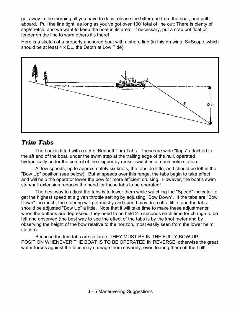
get away in the morning all you have to do is release the bitter end from the boat, and pull itaboard. Pull the line tight, as long as you've got over 100' total of line out: There is plenty ofsag/stretch, and we want to keep the boat in its area! If necessary, put a crab pot float orfender on the line to warn others it's there!Here is a sketch of a properly anchored boat with a shore line (in this drawing, S=Scope, whichshould be at least 4 x DL, the Depth at Low Tide):
Trim TabsThe boat is fitted with a set of Bennett Trim Tabs. These are wide "flaps" attached to
the aft end of the boat, under the swim step at the trailing edge of the hull, operatedhydraulically under the control of the skipper by rocker switches at each helm station.
At low speeds, up to approximately six knots, the tabs do little, and should be left in the"Bow Up" position (see below). But at speeds over this range, the tabs begin to take effectand will help the operator lower the bow for more efficient cruising. However, the boat’s swimstep/hull extension reduces the need for these tabs to be operated!
The best way to adjust the tabs is to lower them while watching the "Speed" indicator toget the highest speed at a given throttle setting by adjusting "Bow Down". If the tabs are "BowDown" too much, the steering will get mushy and speed may drop off a little, and the tabsshould be adjusted "Bow Up" a little. Note that it will take time to make these adjustments;when the buttons are depressed, they need to be held 2-5 seconds each time for change to befelt and observed (the best way to see the effect of the tabs is by the knot meter and byobserving the height of the bow relative to the horizon, most easily seen from the lower helmstation).
Because the trim tabs are so large, THEY MUST BE IN THE FULLY-BOW-UPPOSITION WHENEVER THE BOAT IS TO BE OPERATED IN REVERSE, otherwise the greatwater forces against the tabs may damage them severely, even tearing them off the hull!

3 - 6 Maneuvering Suggestions
Windlass MasterSwitch.
Anchor Windlass; Foot switches to left.
The little “boat” on the control is movedin the direction you want the thrusters
to actually move the boat!
Anchor WindlassThe anchor windlass on the bow is
controlled at either helm. For it to operate, themaster switch in the DC power panel, left (forward)side must be “On”. Then it is controlled by footswitches just to port of the windlass.
If the windlass fails, it can be operatedmanually. Follow the instructions in its operatingmanual in this unlikely situation.
Bow and Stern ThrustersHawthorne Bay has been equipped with bow and stern
thrusters with Bayliner “Dock on Command” controls at eachhelm, and a remote control. These will assist you in getting extraclose to the dock after you have put the boat within three feet orso using the engines...
The thrusters run from their own battery charged by theengines, shore power, and the generator; they are not designedto be used excessively without interruption, as they will overheatand/or exhaust their battery. When a thruster overheats, athermal overload switch will open, so they will only run for acouple of minutes of intermittent use (30 seconds at a time moreor less) before this switch operates to let the thruster cool for asmuch as 15 minutes before the switch closes and allows moreoperation!
Do not overuse the thrusters! Operating them in "jabs" of10-15 seconds at a time should be enough.
To operate the thrusters:: Use the “D.O.C.” Dock on Command control at either helm. Simply push the little
boat-shaped button in the direction you want the boat to move, and the appropriate thruster willrun, pushing water out the boat’s side to move it as needed.

4 - 1 Engine(s) Operation and Maintenance
The starboard engine dipstick and oil fill is theyellow T-handle just above the filter.
The port engine dipstick and oil fill is the yellow T-handle just aft of the forward engine mount.
Section 4: Specific Discussion of BoatSystems
This section of the operating manual will discuss each of the boat's systems in turn. Thesystems and major components discussed are grouped and in order as follows:
Main Engines & Sea Strainers Dinghy, Davit & Outboard MotorFresh Water System;Electrical-AC, Electrical-DC, and Inverter;Heads and Holding Tanks; Heating System; Galley EquipmentNavigation Equipment, Radios, and Radar.
Main Engines, Engine Controls & Sea StrainersThe main engines on the boat are two Cummins Diesels, each producing a maximum of
300 horsepower. These extraordinarily-reliable, rugged machines are the top-of-the-line, andcan be expected to give you trouble-free, economical cruising.
On engine start, no long warm-up is required! Three or four minutes is sufficient, thenload the engines by putting the transmissions in gear. Do not run them over 1400 RPM untilthe temperature gauges read at least 140 degrees Fahrenheit. Do not run the engines for longperiods with the transmissions in neutral, with no load!
Daily Maintenance ProceduresThe engines
require a regular,daily check, sinceonce underway, youwill probably notcheck them while inuse, tucked away asthe are beneath thecabin floor. Pleaseperform this checkeach morning (whenthe engine room iscool!):
CHECK THE OIL. The oil level should be between the two marks on the dipstick. Thedipsticks are located on the inboard side of each engine, at the aft end of the engineitself, fairly low on the crankcase. Use a paper towel from the roll on the aft bulkhead,wipe the stick, reinsert, and take reading. You must remove, wipe, and re-dip the stickto get an accurate reading because the sticks often will be "dry" the first time they arepulled! A funnel for adding oil is by the oil changer in the engine room entrance.

4 - 2 Engine(s) Operation and Maintenance
The distance between the two marks is about 1.5 quarts. Add only enough oil tobring it up above the "add" mark, say a quart, using the oil provided on the boat. (If youneed more oil, buy it! We will reimburse you.) The oil fill on each engine is the capforward on the top of the engine's forward valve cover; you will need to use a funnel toadd oil without spilling.
Do not overfill the crankcase (above the "full" mark), as these engines will quicklywaste excessive lubricant. If oil is required often, check under the engine carefully to besure there is no oil leak, and if there is, have it corrected promptly.
CHECK THE COOLANT LEVEL. There are plastic coolant tanks mounted just behind eachengine (the port one is outboard of the transmission, so difficult to reach). If, when cool,the level is very near the bottom of the tank, add coolant. Do not overfill! When theengines are hot, the coolant will expand and overflow if you add too much!
If coolant is needed (this should be rare), determine if there is any sign of acoolant leak under the engine, and if there is, do not run the engine; if no leak, addcoolant to the tank from the jug of pre-mixed antifreeze/corrosion inhibitor/watersupplied on the boat. You can use the supplied siphon hose in the engine room to addcoolant to the tank.
VISUALLY INSPECT THE ENGINE ROOM WHENEVER YOU'RE IN IT, asking yourself,"Does everything look right?" Look at the pads under the engines and transmissions:While some drips are normal, there shouldn't ever be substantial accumulations of anyfluids!
CHECK THE SEA STRAINERS ONCE A WEEK, OR IMMEDIATELY IF EITHER ENGINERUNS "HOT". The engine strainers and valves are in the aft end of the engine room aftof each engine: you can find them by following the big hoses. The genset sea straineris in the lazarette. To check a strainer, shine a flashlight through it. While some"fuzziness" from trapped thin growth is normal, you should see the light clearly on theother side; if obscured, you should clean the strainer. See below.
CHECK THE TRANSMISSION OIL LEVEL once every two weeks, more often if atransmission shifts erratically. The dipstick is atop each transmission. It is unlikely thatany oil will need to be added. Be sure to check under the transmission for leaks! Lowtransmission oil is a serious matter.
With the engine idling, remove the transmission dipstick. Wipe it with a towel,reinsert it, and take a reading. If the level is below the add mark, stop the engine, add apint of the same oil used for the engine crankcases through the plug in the top of thetransmission case, and then start the engine and measure again. DO NOT OVERFILL,for to do so could cause the seals to "blow out".These Cummins engines are red-lined at 2800 RPM. Maximum cruise is 2400 RPM.
However, the realities of vessel hull design and powerplant engineering dictate that higherRPM operation is very inefficient on semi-displacement vessels like this one, so you will findthese operating specifications to be true (gallons per hour, speeds, and nautical miles/gallonare conservative estimates):

4 - 3 Engine(s) Operation and Maintenance
RPM Speed GPH Total Both Engines Combined Nautical Miles per Gallon
1600 9.0 8.0 1.125
1800 12.0 11.0 .916
2000 14.0* 16 .875
2200 18.5* 22.0 .840
2400 22.0* 30.0 .733
Efficiency of planing hull boats can be stated as follows: For longest range/least fuelconsumption, run at displacement speeds...about 9.0 knots and 1600 RPM. From that throttlesetting up just past planing speed, the fuel consumption increases rapidly, as in the tableabove from 1600 up through about 2000 RPM. Once the boat begins to plane, additionalspeeds are reached with little additional fuel.
The bottom line: Most economical setting: about 1400, but the boat will not be ascomfortable as at a setting just on plane, about 2000-2150 RPM depending upon load, trim tabsetting, and cleanliness of bottom.
* It is important to use a higher setting to get the boat planing, then adjust the trim tabs,then reduce power until it is just high enough to keep it on plane!
Engine ControlsThe engines are controlled by Hynautic hydraulic controls at each helm. Do not let
something interfere with the controls at the helm that is unattended! You will note that theflybridge canvas has “poofy” bags that go over the controls when the canvas is in place: Besure it is clear and does not interfere with control operation.
Make throttle/power changes smoothly, and do not shift quickly from forward toreverse: Always shift slowly through “neutral to protect the transmission except in anextreme emergency.
You will want to be especially careful using these controls until you are comfortable withthem and used to their response times; you can be confident that they will operate properly,but you will need to get used to them!
(Continued on next page)
4 - 4 Engine(s) Operation and Maintenance
Sea Strainer Cleaning & SeacocksThe sea strainers on this boat are secure and reliable. They protect the engine and
refrigeration cooling systems from water-borne debris which might block internal equipmentpassages. If a sea strainer needs cleaning (see above regarding inspection) here is theprocedure:
1) Look at the seacock near the hull. On the side is a valve lever, with a relatively longhandle.
The main engine sea strainers are aft of each engine. The generator seastrainer is in the lazarette.
2) Turn the valve lever so it is perpendicular to the seacock (parallel to the hull).3) Using a spanner from the tool kit, or (depending upon strainer model) unscrew thetop of the sea strainer. Then remove the strainer by pulling it out the top of theassembly. Rinse the strainer thoroughly and, if necessary, remove any debris from theglass housing.4) Reinsert the strainer, tighten the top cover with the spanner, AND TURN THESEACOCK VALVE BACK ON failure to do so will overheat the engine.This entire operation will take 5-10 minutes at most, and will assure you of cool engines.

4 - 5 Dinghy & Outboard Operation and Maintenance
Dinghy, Davit & Outboard MotorDinghy
The dinghy aboard this boat is a Zodiac 12' hard-bottom inflatable, designed to carry upto four passengers safely, with two sharing the seat behind the console, one alongside theconsole, and one in the bow. For safety, and compliance with U.S. rules, there should be a lifejacket aboard the dinghy for each passenger aboard whenever the dinghy is at sea.
Please be careful when pulling the dinghy ashore to minimize damage and scratches tothe bottom. It can be lifted by two persons if one is on each side. Don't "Ram" the beach; youcan bump up to the beach gently and step ashore over the bow, pulling the dinghy a little moreashore as each person off-loads. And raise the outboard with its electric tilt before it hitsbottom when landing on a beach!
The dinghy will seldom require inflation as long as the valve seals are maintained and itis not punctured. Should inflation be required, simply pump up the dinghy until it is pretty hard(thumb can deflect a tube by about «" maximum) using the pump provided on the boat.
Should the dinghy be punctured and you feel competent to make the repair, follow theinstructions in the dinghy manual and use the dinghy repair kit also on the boat; otherwise,have it professionally patched at San Juan Yachting or a dealer's.
Retractable Swim Step Dinghy Fender CleatsOn the swim step are three small pop-up cleats, placed to hold the small fenders to
protect the back of the boat and the dinghy when the dingy comes abreast. Do not use thecleats to tow the dinghy...they are not strong enough!
Dinghy DavitThis boat has a high-quality Roskelley-Ohlson electric davit supporting the dinghy.The step by step instructions are:
1) It’s best to have the generator or an engine running to keep the batteries upduring the time the davit is operated.2) Lift the davit boom and lock it into the raised position.3) Plug the davit control box found in the L-Settee on the flybridge.4) Remove the dinghy's canvas cover and tie-downs if installed.5) Raise the dinghy, swing it to starboard, and launch it (see next page!)6) Swing the davit hook back to the boat, secure it, and tension it on the davit, toavoid damage to the yacht from a swinging davit if the boat rolls.
To retrieve the dinghy on the boat, reverse the above procedure, being sure to tilt themotor up during hoisting so that it doesn’t damage the deck when you lower thedinghy. Then, be sure to reconnect the tie-downs!

4 - 6 Dinghy & Outboard Operation and Maintenance
Motor with cover removed. The dipstick is near the bottomflange for the cover, while the oil fill is the yellow cap.
Outboard MotorThe outboard motor for the boat is a Honda
40 horsepower four-stroke, electric start and tiltoutboard. This outboard is a four-cycle motor, thatis, you need not mix oil with the fuel, it uses regulargas only.
If oil is low (this should seldom happen, ifever!), a warning will appear in the sight-windowjust above the steering handle arm. If this warningis red, stop the motor at once and add oil.
To check the motor's oil, remove the coverby pulling out the “suitcase-style” levers on the frontand rear. After these levers are released, you canlift the back of the cover and unhook it.
You will see the oil fill cap on the aft side ofthe engine, and the dipstick on its starboard side. (Adding oil is tricky: you may need to use a funnelto avoid spilling it.) Do not overfill! There isoutboard oil stored in the starboard cockpit cabinet.
• The choke lever next to andabove the shifter must be raisedto start the motor.
• The engine is raised and lowered while pressing a release button on theport side of the motor support assembly.

4 - 7 Water System Operation and Maintenance
The water heater is hard tomiss in the utility room!
Fresh Water SystemTanks
There is a polyethylene water tank located forward in the bow, and abladder aft under the companionway. These are filled at two fill caps on theforward deck, the forward one filling the tank and the aft one the bladder.The two tanks are interconnected, so they will be emptied together at thesame rate. The water tank monitor gauge at the bottom of the DC electricpanel tells you the level in the polyethylene tank only.
Water PumpThe water line from the tanks leads to the boat's fresh water pump in the utility system
area behind the cabinet door in the companionway. Provided its circuit breaker in the DCpower panel in the salon is "on", this pump will run whenever its built-in pressure switchdetects low water pressure. An "accumulator tank" by the pump provides a "pressure head" forthe pump, so the pump doesn't need to run so often. Instead, a pump cycle will provide forseveral minutes of routine water use before pressure diminishes and the pump starts again.
Because the watermaker automatically flushes its membranes on a regular basis usingwater from the boat’s tanks, the fresh water pump should be left on all the time to allow itto get the necessary water for that process!
Water HeaterAfter the water pump, water is distributed directly to the cold
water faucet lines. In addition, it goes to the boat's water heater. Thisheater uses either heat from the starboard engine (so you have hotwater when underway and after running) or by AC from shore power orthe generator; if available and the breaker is "on it does not run from theinverter power,", or from the generator. The heater is insulated wellenough to keep hot water overnight without power, provided you haven'twasted a lot in dishwashing!
Waste WaterWaste water from the sinks and showers (but not from the toilets) is dumped overboard
in accordance with U.S. and Canadian law. From the various drains above the waterline, thewater simply flows by gravity down and out through waterline-level outlets. The two showersand the guest head sink flow into float-actuated overboard-pump systems also in the forwardutility area accessed from the companionway cabinet doors. It is therefore very important thatthe Shower Pump breakers in the DC panel be left "on".
In the unlikely event that a sump pump fails, drain water will back up in the showers orbasins. Check the switch and circuit breaker if this should happen. If this doesn't solve theproblem, contact SJY.

4 - 8 Water System Operation and Maintenance
The watermaker control is inthe pilothouse above the
power panel. The Link 10monitor and speaker control
for nearby speakers arebelow it.
WatermakerThe boat carries a Spectra Watermaker. This great system
(which requires DC power to operate) has the following features:! It automatically flushes itself on a regular basis to keep
the filtration membranes clean and in service;! It has automatic controls that run it for specific periods so
that you need not worry about overfilling tanks andwasting water;
! It assures you that there will always be plenty of water,however it will take several hours to top off the tank undernormal use.
! Note that you can use city water without filling the tanks.Simply connect the hose to the pressure water inlet fittingoutside the cockpit swim door and leave the hose “on” aslong as you are at the dock; this will then go directly to theboat’s faucets as needed, but not into the tanks.
Operation is entirely automatic. Simply push the button to addwater to the tanks, following these provisos:
! Do not run the watermaker while in the harbor: Youwill shorten the time that the filters can be in service;
! Leave the watermaker on at all times so it can monitor its own operations.! Always leave the fresh water pump breaker on so that the purge system
can operate properly!

4 - 9 D.C. Elec. System Operation and Maintenance
Here is one of the battery boxes (for thethrusters). This one is in the utility room underthe hatch at the aft end of the companionway.
Other batteries are in the lazarette.
DC Electrical SystemConcepts
Each year it seems more folks are confused by theoperation of electrical systems on yachts than by anyother subject! Don't feel discouraged if something isn'tclear: You've got company in your confusion. So let's tryto cover some theory here first.! Most of the equipment on any boat is run by 12 volt
DC electricity from the boat's batteries. This is truebecause DC should always be available: We havebatteries aboard even when there is no shorepower! If the batteries aren't run down, everythingshould work, just like in the family car.
! Since the batteries are used so much, we have toreplenish, or charge them. The most important waywe do this is by alternators on the ship's engine(s). In most cases, one engine willprovide enough electricity in most every case to run everything, and still have someenergy left over to add back to the battery, that is, to charge it.
! What if the engine(s) isn't running? Then, the batteries are slowly depleted until theyhave "run down" and there is no more electricity in them . . . a big problem, becausethen we not only can't run all the stuff on the boat, we can't start an engine to get moreelectricity.
! So a good skipper and crew has "electrical power management" in mind whenever theyturn an electrical gadget on or off!With this in mind then we can state: If we need more electricity than the batteries alone
can provide, and if a propulsion engine isn't running, we will need to get our electrical powerfrom an alternative source! That's the most reason why we use shore power or use thegenerator: To keep from running down the batteries. For by using battery chargers getting theirpower from shore power or the genset, we can keep the batteries charged, or, at least, fromgetting too low.
In modern, luxury cruising boats, however, there is another important factor: Some ofthe "goodies" we like to have on board such as hair dryers and microwave ovens requireordinary household electricity. This is 110 volts AC. It is different from DC. So if we want touse these things when we're not at a dock, we must have another way to get 110 volts AC, andfor this we use the generator or an inverter, an amazing high tech gadget that takes 12 voltsDC from the ship's batteries and makes it into 110 volts DC!
So here's what we've got: A lot of stuff running on 12 volts DC from the batteries. Tokeep the batteries from running down, we have alternators run by the engines, and batterychargers that get their power from shore power or the genset. For the stuff that runs on 110volts AC, we have shore power, the generator, or, for making AC out of the batteries' DC, theinverter.

4 - 10 D.C. Elec. System Operation and Maintenance
Battery BanksThe batteries on this boat are not just one, big all-purpose battery. To have
redundancy, there are actually several "banks" of batteries assigned different tasks.Two batteries are used to start the engines, one for each. Another battery starts the
generator. Because these batteries only start the motors, we can't run them down playing thestereo for instance, then be unable to start an engine.
A group of batteries called "the house battery" are all tied together (paralleled); these run the inverter, all the pumps, interior and exterior lights, horns, navigation and radio gear,etc. In other words, this bank runs the boat's "house". They are also charged when there isshore power or the genset is running by the inverter, which serves as a high-capacity charger.
Another battery is for the bow and stern thrusters (this battery is in the front of the utilityroom under the hatch at the top of the companionway steps), and it is charged by engines orchargers.
The engine starting batteries, and the house battery, are also charged whenever eitheror both engines are running: DC Electricity comes from the engine alternators to a batterycombiner and from it to all three batteries.
For instance, if any starting battery is run down and we can't start an engine or thegenset, we can still start another and it will begin charging the deficient battery. Then we canstart the engine itself that had the once-dead battery. Or we can start the generator, and let itcharge all the batteries.
Since a battery works by making electricity through a chemical reaction, one componentof which is water, we need to be sure the batteries have water in them; this battery servicing isnormally done routinely every few weeks by the boat's owner or charter company.

4 - 11 D.C. Elec. System Operation and Maintenance
The DC Electrical PanelThe nerve center of the DC electrical system is the combined
AC-DC circuit breaker panel on the starboard side of the pilothouse aftof the side door. On this panel are the switches that control power tothe boat's various systems.
Just as in your home, most of these switches are true "circuitbreakers": They feed power to somewhere in the boat where there isanother switch which, in turn, turns the item on and off. An example ofthis would be the circuit breakers for the spotlight or cabin lights: If thebreaker is turned on, the light still won't work unless you turn its switch!
Some of the breakers also serve as the switch for the item. Anexample of this would be the engine room lights. ("B" means used ascircuit breaker, "S" means used as switch AND breaker.)
Breaker Use BreakerUse
Waste Discharge (2) S Push both to pump overboard S/R Lights B To SwitchesDC Master S DC Master Switch Head Lights B To SwitchesIgnition Power (2) B To Ignition Switches Passageway Lights B To SwitchesHorn B To Horn Buttons Exterior Lights B To SwitchesE/R Blower S Turns on E/R Blower DC Stereo B To StereoBilge Pumps (3) S Manually Turns B. Pumps On TV/VCR B To TV/VCR CabinetNav/Anchor Lt B To Switch Head Blower B To SwitchesWiper(s) (3) B To Switches RIGHT COLUMNWasher/Defroster B To Switches Washdown Pump B To Pump Pressure SwitchRadar B To Radar Head Pumps (2) B To Pump Vacuum SwitchesAutopilot B To Autopilot Holding Tank Discharge B To Waste Discharge SwitchesDepth Sounder B To Depth Sounder Tank Monitor S Turns on Tank MonitorElectronics B To Other Electronics Water Pressure B To Pump Pressure SwitchMIDDLE COLUMN Shower Sump Pump B To Pump Float SwitchesSearchlight B To Searchlight Refrigerator B To FridgeEngine Room Light S Turns on E/R Lights Trim Tabs B To Trim Tab SwitchesPanel Lights B To Panel Lights Accessory #1 B To F/B DC OutletSalon Lights& LPG B To Switches & Propane Sw. Accessory #2 B To DC Panel & ComGalley Lights B To Switches Accessory #3 B To Head Water PumpPH Lights B To Switches Accessory #4 B To Fuel Transfer PumpM/S/R Lights B To Switches Tub/Sink Sump Pump B To Accessory
METERS AND ROTARY SWITCHES ON DC SIDE OF POWER PANELDC Voltmeter Reads voltage per battery selector Off-Port-Stbd-House-GenPort-Stbd-Generator Hours Reads engine hoursTankwatch Holding tank alert: Lights show level; Red Light indicates fullWater Level Monitor Reads Tank #2 (only) per adjacent switch

4 - 12 D.C. Elec. System Operation and Maintenance
Link 10 DC Power MonitorAbove power panel is a Link 10 DC Energy
Monitor. This nifty unit allows you to check DChouse battery voltage, charging/use rates in amps,and approximate cumulative battery energy used.
Across the top are the green LED’s thatindicate the state of the batteries’ charge, from“empty” (on the left) to “full” (on the right).
There are two buttons on this unit’s panel,“SEL” and “SET”. You will use only the “SEL”button! When pressed, it cycles the monitorthrough the “V”, “A”, “Ah” and “t” steps, illuminatingthe small LED’s, representing “Volts”, “Amps”,“Amp-Hours”, and “Temperature”.
In the “V”, “Volts” mode, the unit displays thepresent house battery voltage.
The “volts” mode will display between 10 and 15 volts, with 12.8 fully charged,nothing running; 14.2 or more bulk charging; 13.2 - 13.8 float charging, less than10.0 volts, discharged.
In the “A”, “Amps” mode, the unit displays the rate of charge or discharge of the housebatteries; a “-” sign appears when the battery is discharging, no sign when charging.
In the “Ah”, “Amp-Hours” mode, the unit is like a “fuel gauge in reverse”. When thebatteries are fully charged, the unit should show approximately “0". Then, as ampere-hoursare used, the unit counts them, i.e., after you’ve used 50 amp-hours, the unit will display “-50"or so.
The amp-hours readings are approximate, and relative. When you run the boat,the number should decrease again to zero. In fact, the most useful setting for theenergy monitor is the amps mode, which answers the question “Am I using up (-)or adding power to the batteries right now?”
We suggest you look at the monitor especially just before bed when at anchor, to warnyou if you’ve left something on. You will normally see only a modest “-” current for your anchorlight and perhaps the fridge. If nothing is running, voltage should be about 12.6 - 12.8, fullycharged.
After you wake up, check the voltages before you start using more DC energy: You maywant to charge your batteries by “going for a boat ride” or using the generator if you were atanchor.
If you take readings frequently for the first day or two of your cruise, you’ll get an idea ofnormal system operation and power consumption rates.
Link 10 monitor (sistership photo).

4 - 13 A.C. Elec. System Operation and Maintenance
The AC Electrical SystemThe AC Electrical System is controlled at two sites, the AC
circuit breaker panel and the Inverter control panel.These panels have the switches that control the boat's AC
electric systems.In addition, there is an AC voltmeter and AC ammeter in the AC
panel. This allows the skipper to monitor power usage to determinewhether the generator or shore power is needed.
Just as in the case of the DC panel, the AC panel has somecircuit breakers which are also switches ("B" means used as circuitbreaker, "S" means used as switch AND breaker.): room lights. ("B"means used as circuit breaker, "S" means used as switch ANDbreaker.) There are several switches on this panel, too; they aredetailed on the next page.
Breaker Use Breaker Use
Polarity Safe/Hazard Warning Light!* M/S/R & Head Recept B To ReceptaclesLINE 1 The next two select source: Aft S/R & Head Recept B To ReceptaclesDockside Master S Source of Line 1 OR Microwave B To Microwave OutletGenerator Master S Source of Line 1 Central Vac. B To Central Vac. OutletWater Heater B To W.H. Thermostat Washer/Dryer B To W/D Outlet Trash Compacter B To Trash Compacter Accessory #3 B To Accessory #3Battery Charger S Turns on Battery Charger Inverter Output B From Inverter to ReceptaclesSalon/PH Receptacles B To Receptacles RIGHT COLUMNGalley Receptacles B To Receptacles Polarity Hazard/Safe Warning Light!*Icemaker B To Icemaker Outlet Line 3 The next two select source:Blender B To Blender Dockside Master S Source of Line 3 ORAccessory 1 B To Accessory #1 Generator Master S Source of Line 3Inverter Input B To Inverter M/S/R Heater B To Heater-Master
MIDDLE COLUMN Hall Heater B To Heater-HallwayPolarity Safe/Hazard Warning Light!* Salon Heater B To Heater-SalonLine 2 The next two select source: PH Heater B To Heater-PilothouseDockside Master S Source of Line 2 OR Accessory #5 B To Accessory #5Generator Master S Source of Line 2Entertainm’t Ctr/Internet B To Ent. Ctr & Internet Recvr.Refrigerator B To Refrigerator Outlet
* If the “Polarity Hazard” Light illuminates, disconnect shore power at once!
Voltmeters & Rotary Switches on AC Side of PanelVoltmeter Selection Selects Line 1-2-3 & Generator readingNormal-Off-Line 1-2 parallel on line 1 Recept. Allows Line 1 to Also Power Bank 2Normal-Off-Line 1-3 parallel on line 1 Recept. Allows Line 1 to Also Power Bank 3Generator Start-On-Off See Below
Connecting/Disconnecting Shore Power

4 - 14 A.C. Elec. System Operation and Maintenance
The shore power connectors are on the starboard side ofthe boat just aft of the side door. The left connector is for
TV/phone, while the others are Line 1, 2, & 3.
The two breakers at the top left of eachcolumn select between the shore power “Dockside”line connector at side of the boat just aft of thestarboard side door and the generator's power. You will see that only one can be "on" at one time! But, of course, both can be "Off".
You will want to turn "Off" the “Dockside”breaker before you connect or disconnect the boatto shore. This is true so that you do not draw anarc from the plug due to the load of the boat on theconnector's pins: Such an arc will burn the contactsand eventually cause them to overheat when inuse, creating a fire hazard.
Once connected to shore power, monitor theAC "line voltage" voltmeter and "line current"ammeter to be sure you have not overloaded the circuit.
With the “Normal-Off-Line Parallel” switches you can run all three switch columns off ofone shore power cable if more 30-amp connections are not available at the dock. You mayneed to run the generator even at the dock if you want to use a lot of AC power! Becareful not to overload the shore power connections.
Important Note: If the house batteries are low when you first hook up to shore power,and the inverter is turned on (as it should be), the inverter will begin charging its batteries at avery high charging rate, drawing a lot of shore power current. Until this demand reduces (see"The Inverter System" below), you should turn "OFF" other high-current AC appliances such asthe water heater.
You can then turn on AC appliances as needed. Watch the ammeter to be sureyou don't exceed the dock's available supply, typically 30 amps.
Here are some estimates of AC power consumption for typical appliances:
Item Amps Item Amps
Water Heater 15 Coffee Maker 10
Hair Dryer 12 Microwave 10
TV 1.5 Cell Phone .3
Refrigerator/Freezer 7 Inverter (After batteries charged) 1 - 3

4 - 15 Inverter System Operation and Maintenance
The Inverter SystemAs we said, the Inverter system is used to provide AC to the boat when there is no
shore power. It is useful for the inverter to run the refrigerator and freezer, to make a pot ofcoffee when the engines are running underway, or to watch TV in a quiet anchorage, or use ahair dryer for a few minutes. But for long-period use of AC by large appliances, the enginesmust be running or you must have shore power available. That's because the boat's housebatteries store about 300-400 amp-hours of electricity, that is, they can produce 100 amps forfour hours, more or less.
Now the microwave, for example, will draw about 100 amps of DC when using theinverter to run it, so in 15 minutes you use one-quarter of an hour at 100 amps, or 25ampere-hours. That means that in fifteen minutes, you've consumed almost 10% of the housebatteries' stored power. That's okay. But what if you want to cook a roast for 60 minutes? Youuse up one-quarter of your energy on that one job alone! That's too much use for the inverter!Use the generator!
For a short task, the inverter is great: No need for a generator, no noise, no fuss, thepower is there. If the engines are running, use it all you wish, as long as you don't try to do twobig jobs at once: The inverter can only produce 4,000 watts of energy at a time. So theinverter is only wired to certain outlets, the microwave, and the refrigerators. It will not run thewater heater, boat heaters, air conditioning or battery charger. Electrical portable heaters,particularly, should never be run by the inverter!
But in addition to making AC out of DC, the inverter can do the reverse! If there is ACavailable from shore power, it will charge batteries! You tell what the inverter is doing by itscontrol panel.
The inverter is behind the L-Settee in the aft wall of the salon, with vents behind thecockpit ladder.
The inverter hums when it is on. This is normal. If loads are high, italso has a cooling fan that runs as necessary that you may hear; ifyou do, it’s an indication that all is well.
(See next page)

4 - 16 Inverter System Operation and Maintenance
In summary, the inverter should be onwhenever shore power is present or the generator isrunning, and it may also be left on when underway. Itis a good idea to turn the inverter off at anchor (whenthe generator isn’t running), turning it on only whenyou want to use something briefly, as above; in thisway, you will avoid running down the house batteriesjust because someone left some AC applianceplugged in and forgotten.
STATUS LIGHTS LIT MEANING OFSTATUS LIGHTS
“INVERT” Inverter is MAKING AC and consuming batteries
“STANDBY” Inverter is on, but idling
“POWER: UTILITY/SHOREPOWER AC Power is coming IN to the Inverter.
“CHARGE” Inverter is charging house and inverter batteries
“FAULT” or “TEMP” There is an error condition. Press “Reset”. If it doesn’t clear, consult manual.
INVERTER BUTTON FUNCTION
“ESCAPE” See note below Moves up one level in the menu tree
“ENTER” See note below Selects the displayed menu item
“�” and “�” See note below Moves through selections at this menu level
“INVERTER ON/OFF” Toggles the inverter on and off
“CHARGER ON/OFF” Toggles the charger on and off
Note: Please consult the instruction manual before using these controls for other thanmeter readings!Important! Remember the important note above under “Connecting/Disconnecting ShorePower”: The inverter, if on, will draw a lot of current when bulk charging, so be carefulnot to overload a shore power circuit. If “AC Present” and “INV/CHRG” are both lit, and“Battery Amps” shows more than 30 amps, this higher load is being drawn from the 110-volt AC supply.

4 - 17 Generator System Operation and Maintenance
The Generator SystemThe ship's Westerbeke Generator provides 8,000 watts of AC power to the vessel and is
mainly used for battery charging, refrigeration, cooking on the range and microwave, heatinghot water, and occasional heating. Generally 1 to 3 hours of operation daily will recharge theboat's batteries.
Given that distances are short in the Pacific NW (one of its appeals!) you may only runthe main engines a couple of hours on a given day. This may not be enough to recharge thebatteries fully since the engine alternators are not as effective a charging source as thegenerator combined with the inverter. Take this into account in your power budgeting.
The generator is in the engine room at the forward center, and its oil and coolant levelsare checked before each charter by the SJY staff. More important when traveling is checkingthe sea strainer (see previous section) to be sure is has not accumulated substantial debriswhile the generator was run for extended periods, particularly at anchor.
The generator stop/start controls are on the bottom of the AC panel.
Starting the Generator:1) Hold down the rocker switch on the bottom left of the power panel in the
"Preheat" position for 15 seconds (this energizes "glow plugs" to warm the engine's cylinders).2) While still holding the “Preheat” switch, turn and hold the generator control switch
in the "start" position until the engine starts. If the engine does not start in 15 seconds, repeatstep one and try again. Do not repeat more than twice lest the exhaust system becomeswater-locked, possibly damaging the genset!*
3) Check the generator exhaust under the swim platform, listening to it to confirmthat cooling water is being pumped from it.
4) After a brief warmup of a minute or so, switch the circuit breakers in each of thethree breaker columns in the AC power panel from "Dockside" to "Generator". You should seethe "AC Present" pilot light go on!
* If you need to try more than twice, shut off the seacock to the generatorsea water inlet so that you do not fill the exhaust system with water. Then,as soon as the generator starts, turn the seacock back on immediately!
Stopping the Generator1) Switch the "Generator" circuit breakers in each of the switch columns in the AC
panel off. This removes the load for the generator and allows it to cool down.2) After at least a minute to allow the generator to cool down, switch the “generator”
rotary switch to “off”. The generator will stop.

4 - 18 Generator System Operation and Maintenance
Generator Problems The generator monitors its own operation! It was two fault-detection systems: one ofthese will detect any loss in oil pressure, the other detects overheating. If either conditionoccurs, the generator will shut itself off, and it then will not keep running when you try to restartit. The start switch overrides the low-oil shutdown while the oil pressure builds.
There are two generator components that are subject to charterer service: Coolant andlubricating oil. The fills for both are located within the Westerbeke sound shield through thecenter hatch in the lazarette. The coolant is in the heat exchanger atop the engine, while theoil is harder to service: The dipstick is under the muffler on the starboard side of theengine, with the oil fill adjacent. (You should not have to deal with these: They are difficultto service. Call San Juan Yachting.)
Do not remove the water fill cap from an overheated engine. Let it cool, then removethe cap slowly with protective clothing on in case high temperature steam escapes. If oilpressure is the problem, check the oil level and top up. However do not attempt to re-start ifthe oil level is normal and you have checked the cooling system including the raw waterstrainer if one of these is not the problem then the shutdown is protecting the engine fromdamage due to an internal failure.
If the generator will not keep running, call San Juan Yachting for assistance.

4 - 19 Head System Operation and Maintenance
Heads & Holding TanksHead System Overview
The head system on this boat is reliable, straightforward, and easy-to-use.First, a note about discharge of sewage:
It is forbidden to discharge untreated sewage in inland US. waters, an areathat includes all US. waters in which this boat operates. The boat holding tankmust only be emptied at proper pump-out stations if it is in US. waters. (Withthe exception of certain Canadian Harbors which are no-discharge zones, Thisrule does not apply in Canadian waters. However, in Canada, courteouspractice dictates that the holding tank be dumped only when outside allconfined marinas or bays, as we are sure the reader agrees!)
The boat is equipped with electric Vacu-Flush heads. These heads each have aseparate pump which macerates waste and puts it either into a holding tank. The holding tankis emptied either of two ways: By operating an overboard macerator pump controlled at the DCpower panel and by a switch and Y-valve in the engine room, or by pumping it using a shoreside pump out station through the boat's side-deck pump out fitting.
The Vacu-Flush HeadsThese premium heads are easy to use, odor free, and very reliable. They work with two
separate vacuum pumps and vacuum accumulator tanks. A vacuum is maintained in the tankuntil the head is used, when the waste matter in the bowl is sucked out of the head by thevacuum, then it is pumped through the system by the head pump, which then also pumps up avacuum again. Note that it is this rush of the head's contents caused by the accumulatedvacuum that is important to the head's operation! This sudden rush causes any solid materialin the waste stream to be shattered as it passes through the specially-shaped orifice in thebottom of the head. For this reason, proper head operation requires that the head pedal notbe held down for long periods if time.
The head uses about a half pint of fresh water from the ship's supply with each flush.The head is operated by a the pedal to the left of the head base (as you face the head),
and operation is as follows:1) Be sure the circuit breaker for the head on the DC Power Panel is "On".
The switch for each head should be left on unless you have trouble with the head(see below), in which case you will turn the switch "Off". Using a head withoutits switch “on” risks a clogged system!
2) Before using the head if the waste will be solid, lift the pedal to add water to the bowl;3) Use the head;4) Step on the pedal just long enough to hear the "whoosh" as the head is evacuatedand a small amount of water rinses the bowl - - - about five seconds!5) Releasing the pedal, if you wish to flush again, wait at least twenty seconds or so(until you hear the head pump stop) before flushing again.As the pedal is released, the ball-valve at the bottom of the head seals it so that the
vacuum can be pumped up, the pump will then stop, and the head is again ready for use.If the head pump runs often or steadily between flushes, it is likely that the seal at the
bottom of the bowl did not seal completely: you can tell if there is no water in the bowl. The

4 - 20 Head System Operation and Maintenance
solution is usually simple: Flush the head again and make sure the pedal comes all the way upwhen you remove your foot from it; then make sure the water doesn't leak out.
Only things which were eaten or drunk, or the toilet paper supplied with the boat,should be put in the heads! Facial tissues, tampons, and other foreign matter willclog the system. If these heads are used properly, they are quite reliable. Failures arevirtually always due to mis-use! When it comes to tissue, usually "four squares isenough!"In US. Waters, the Coast Guard Rules require that the valves be "secured" in theholding tank position to assure that all effluent will be kept aboard in the tank. If youturn the valves to overboard while in Canadian waters, re-secure them with the wireties supplied and stored near the valves when you return to the U.S.! See below.
Holding Tank Level IndicatorThere is a holding tank level indicator in the bottom of the DC
breaker panel. It shows the level by illuminating lights as each stageis reached.
Note that the green light is lit when the tankcontains effluent, but has not reached the“Low” level. It may take a minute after emptyingthe tank for the contacts on the empty sensor toclear.
Holding Tank PumpoutThere is a holding tank located to starboard of the companionway just forward of the
engine utility room. Hawthorne Bay is equipped with a holding tank indicator in the DC powerpanel. A deck plate on the starboard side deck below the salon window allows pumping thetank at a shore-side waste pumpout station.
To pump the tank overboard directly into the sea where legal, you must:1. Turn "on" the "Holding Tank Discharge" breaker in the DC panel by thesalon-pilothouse steps.2. Be sure the "Waste" seacock just forward of the starboard engine is open.3. Operate the two rocker switches on the upper edge of the DC power panel; youmust hold these as long as you wish the pump to run. Do not let the pump run dry: Itwill be damaged! The effluent passes through the hose to the pump and out throughthe thru-hull valve.5. When you are done, re-secure the thru-hull valve with a wire tie and turn off thepilothouse DC panel "Waste Pump" breaker.
Y-ValvesThere are no Y-Valves on Hawthorne Bay.

4 - 21 Heating/Air Conditioning System
Just above the wet bar in the salon are the DieselFurnace Thermostat and main switch (top) and
an electric heater thermostat (bottom right).
Diesel furnace exhaust is thelarge outlet in the white hull
topsides.
Heating SystemsDiesel Heater
The boat is equipped with an Webasto DieselCirculating Hot Water Heating System. This is a verycompact furnace located in the lazarette that burns thesame Diesel fuel as the engines. The fuel comes fromone of the engine tanks, but it uses a negligible amount offuel, about a pint each hour it actually runs. The furnaceheats hot water which is circulated throughout the boat. A “System Heat - Off” switch is the main switch; athermostat in the salon regulates the temperature.Individual blowers, each with its own “off-low-high” switch, then force the air into each area of the boat from smallheat exchangers in each area. In addition, the furnacehas an “Everhot” heat exchanger that supplies hot waterto the boat.
To run the furnace, turn the Heater Switch adjacent above the starboard cabinet by thestereo in the salon to “System Heat”. Then, adjust the thermostat to the desired level. Thefurnace’s built-in computer will warm up the furnace (taking several minutes), supply heat tothe boat until the thermostat senses it is warm enough, then shut off the fans while the furnacegoes through a “cool-down” cycle. You need not do anything but set the thermostat with theswitch “on”!
To control the balance of heat between the boat’s areas, use the individual fan controlswitches by each fan, or open, close, or re-direct the deflectors on the outlets.
As you can see, this furnace system is very flexible and a greataddition to the boat! As long as the batteries can support the modestDC power requirement of the fans and furnace blower, you will haveplenty of quiet heat. In fact, this use of the house batteries’ energy forair circulation is a good reason to limit use of the furnace to times whenpassengers are awake, unless the boat has shore power available.
Caution! The Diesel furnace exhaust is on the boat’sport side just forward of the stern. When the furnace isrunning, this is very hot! DO NOT HANG FENDERSNEAR IT, THEY MAY CATCH ON FIRE! Keep clear ofwooden docks, Hawthorne Bay’s dinghy, and/or othervessels!
Electric HeatersThe boat is also equipped with electric built-in heaters in each area, controlled by
thermostats throughout the boat. When shore power is available and adequate, this is veryuseful! The electric heaters can also be used whenever the generator is running.
To use, be sure the appropriate Heater breaker(s) in the AC panel is/are on, then simplyturn up the thermostat!
If using shore power, monitor loads carefully! Each electric heater drawsaround 12 amps!
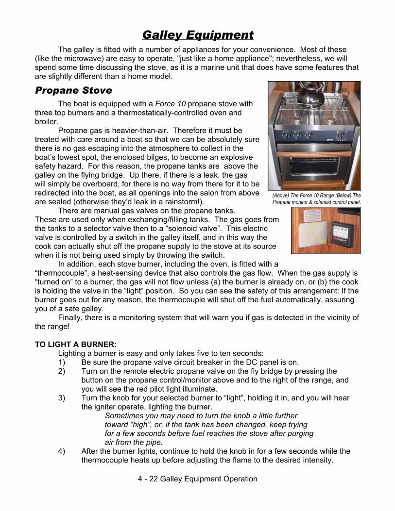
4 - 22 Galley Equipment Operation
Galley EquipmentThe galley is fitted with a number of appliances for your convenience. Most of these
(like the microwave) are easy to operate, "just like a home appliance"; nevertheless, we willspend some time discussing the stove, as it is a marine unit that does have some features thatare slightly different than a home model.
Propane StoveThe boat is equipped with a Force 10 propane stove with
three top burners and a thermostatically-controlled oven andbroiler.
Propane gas is heavier-than-air. Therefore it must betreated with care around a boat so that we can be absolutely surethere is no gas escaping into the atmosphere to collect in theboat’s lowest spot, the enclosed bilges, to become an explosivesafety hazard. For this reason, the propane tanks are above thegalley on the flying bridge. Up there, if there is a leak, the gaswill simply be overboard, for there is no way from there for it to beredirected into the boat, as all openings into the salon from aboveare sealed (otherwise they’d leak in a rainstorm!).
There are manual gas valves on the propane tanks. These are used only when exchanging/filling tanks. The gas goes fromthe tanks to a selector valve then to a “solenoid valve”. This electricvalve is controlled by a switch in the galley itself, and in this way thecook can actually shut off the propane supply to the stove at its sourcewhen it is not being used simply by throwing the switch.
In addition, each stove burner, including the oven, is fitted with a“thermocouple”, a heat-sensing device that also controls the gas flow. When the gas supply is“turned on” to a burner, the gas will not flow unless (a) the burner is already on, or (b) the cookis holding the valve in the “light” position. So you can see the safety of this arrangement: If theburner goes out for any reason, the thermocouple will shut off the fuel automatically, assuringyou of a safe galley.
Finally, there is a monitoring system that will warn you if gas is detected in the vicinity ofthe range!
TO LIGHT A BURNER:Lighting a burner is easy and only takes five to ten seconds:1) Be sure the propane valve circuit breaker in the DC panel is on.2) Turn on the remote electric propane valve on the fly bridge by pressing the
button on the propane control/monitor above and to the right of the range, andyou will see the red pilot light illuminate.
3) Turn the knob for your selected burner to “light”, holding it in, and you will hear the igniter operate, lighting the burner.
Sometimes you may need to turn the knob a little furthertoward “high”, or, if the tank has been changed, keep tryingfor a few seconds before fuel reaches the stove after purgingair from the pipe.
4) After the burner lights, continue to hold the knob in for a few seconds while thethermocouple heats up before adjusting the flame to the desired intensity.
(Above) The Force 10 Range (Below) ThePropane monitor & solenoid control panel.

4 - 23 Galley Equipment Operation
Propane TanksThere are two propane tanks on the flybridge that provide
cooking gas to the range, and there is a changeover valve thatautomatically keeps the gas flowing until both tanks are empty.
Both tank valves on the tanks themselves should be ON.The changeover valve handle selects the first tank to use.
The valve handle points left to select the left tank first, or right toselect the right tank first. (In the illustration, the right/starboardtank is in use first.) Once the first tank is selected, the valve willautomatically switch to the second tank when the first isexhausted, and the indicator band just below the black cap onthe top of the valve will change from green to red indicating thatthe second tank is now in use.
RefrigeratorThe boat is equipped with an efficient Norcold electric
refrigerator that runs on DC; if AC is available, it automaticallyswitches to AC power.
Refrigeration is controlled by the thermostat in the back ofthe refrigerator; set as required after allowing the refrigerator tostabilize for a few hours after loading.
Because of its insulation, the fridge will stay cold a longtime! If you wish, and you have kept the door closed for thepreceding hour or so, you can shut the fridge off at night when at anchor to save batteries; butbe sure to turn it on again in the morning!
IcemakerLocated in the cabinet next to the wet bar in the salon, this
is a conventional unit. To stop its ice production, lift the arm. Itis quite efficient and can produce ice within a half-hour or so. Ituses fresh water from the vessel’s tanks.
Trash CompactorThere is a trash compactor in the galley. Stow waste in it
within a proper trash compacter bag, then operate the control tocompact trash.
BarbecueThere is a Magma Barbecue on the boat deck. To use it,
remove the cover, open the lid, connect the fuel hose, turn on thevalve on the dedicated propane tank, then operate the valves onthe barbecue itself. Be sure to disconnect the hose and turn offthe tank valve when done!
(Above) The propane tanks, control above.(Below) The control. Arrow points to
indicator band.
The compactor is simple to operatewith only one control.

4 - 24 Navigation Electronics & Radios
Electronic Navigation & Radio EquipmentOverview
The boat is equipped with extensive electronic equipment, including VHF radios, a radar, a plotter with GPS receiver, a depth sounder, and an autopilot. The equipment hasrepeaters for all data on the flying bridge.
The DC power supply for this equipment is controlled by electronics circuit breakers inthe DC power panel. Each unit then also has its own power switch.
This manual does not attempt to provide operating instructions for any of the electronicequipment. Instead, you are referred to the equipments' own manuals and “quick start” cardskept in the pilothouse cabinet above the settee. Please be sure to return the manuals andcards to this location.
VHF RadiosThe VHF radios' controls are at both helm stations,
in the Pilothouse and on the flying bridge. The radios aredesigned for easy access to Channel 16, which is thehailing and emergency channel in the Northwest. Otherbuttons allow you to select different channels, weatherchannels, high and low power, and US/Internationaloperation. Your checkout skipper and/or the radio's owninstructions will quickly familiarize you with basicoperation.Be sure to re-check the squelch each time you turn it on.
RadarThe boat is equipped with a radar set. This can be
used, combined with the electronic chart unit, for operationin restricted visibility, with the radar primarily serving as adevice for collision avoidance while the chart unit providesposition.
Proper and safe use of a ship's radar requires lotsof practice and careful study. While you are using theboat, you can have the radar on as much as you like toget used to the way it displays images, but for detailedoperating instructions we refer you to the radar's owncomplete manual and details bottom of next page.
Note that charterer's insurance DOES NOT PERMIT OPERATION OF THEVESSEL IN RESTRICTED VISIBILITY. You should confine your use of theradar to familiarization and training only in weather with good visibility.

4 - 25 Navigation Electronics & Radios
GPS and Electronic Charting SystemThe boat is equipped with a Raytheon GPS and Electronic Charting System to make
your location easily identifiable. One unit is at the lower helm and a repeater is at the upperhelm. Operation is described fully in its manual on the boat and below.
It uses the same display as the radar pictured on the preceding page. It can be in theRadar Only, Radar & Plotter, or Plotter Only mode.
REMEMBER: THE ELECTRONIC CHARTING SYSTEM IS NOT A SUBSTITUTEFOR CAREFUL STUDY OF TRADITIONAL PAPER CHARTS. You are requiredby maritime law to use your paper charts for navigation information,especially since electronic chart technology does not always permit fullcartographic details to show, especially underwater hazards. The electroniccharts are for convenience only!
Raytheon AutopilotThe boat is equipped with a Raytheon "Raypilot"
Autopilot. The primary control is at the lower helm. A secondsmaller remote control is at the upper helm on the port side ofthe console. The autopilot also has a rudder display at eachlocation, but for it to work, the autopilot breaker must be on.
Here is the function of each button:Lights Press for 1 second to turn on
the dial lights; press briefly topage through display modes.
+1, -1, +10, -10 Press to correct course by specific number of degrees. Holding willincrement continuously.
Standby Disengage the autopilot back to "standby" mode.Auto Engage the autopilot and steer the present course.Track Links the autopilot to the navigation course plotters.
Please do not use this function!
Basic operation of the autopilot is simple:1) To turn on the unit, push the "Stby" button to be in the"standby" mode. The unit willdo a quick self-test, then display its present heading.2) To engage the autopilot, push the “Auto" button. It will hold the present heading.3) To disengage the pilot, push "Standby", the unit returns to "Standby".4) Pressing the standby button on either control takes control at that location. Once incontrol, that station stays there until the other station takes control by pressing standby.ALWAYS MAINTAIN A CAREFUL LOOKOUT WHEN USING THE AUTOPILOT! It is
an aid to comfortable cruising, not a replacement for an aware, diligent helmsperson! Remember, you can disengage it quickly at any time simply by pushing "Standby"!

4 - 26 Navigation Electronics & Radios
Weather InstrumentsHawthorne Bay is equipped with
traditional weather instruments above thepilothouse helm. These include aBarometer, Clock andThermometer/Hygrometer.
Graphic Fishfinder/SounderNote: Northwest waters are rocky anddepths change rapidly. You should beespecially careful to study your charts, andthen check them often whenever running inlesser depths, so that you don't hit a rock!Just as our islands "pop up" to heights of50, 100, or even thousands of feet in a verysmall distance, so do rocky obstaclesunderwater!This unit shows you a continuous plot of the sea
bottom as you progress. It’s helpful to see trends indepths, and is a backup to the digital sounder above.
“Backup” Depth SounderAn additional depth sounder is supplied as well. It has a readout
under the wind meter on the port side of the console in the pilothouse. Because the depth sounder transmit their“ping” on the same frequency to receiveechos from the bottom, only one soundershould be “on” at any one time. Turn offthe flybridge sounder when operatingfrom the pilothouse, and vice-versa toavoid this interference and erroneousreadings!

5 - 1 "What to Do If"
Section 5: "What to Do If"ANCHOR CHAIN WON'T COME OUT OF CHAIN LOCKER
The anchor chain is continuous, secured at both ends, and cannot tangle. Butsometimes a pile of chain will fall over, and one loop of chain will fall through another loop. Usually you can clear this by grasping the chain where it exits the hawse pipe from the chainlocker with your hands, and pulling it up or down to "jiggle" the loop out of the chain; you mayhave to retrieve some chain to do this, in order to have enough slack to jiggle it! It is rare whenthis will not clear the jam. The other solution: go below and clear the tangle in the chain locker. Caution: Turn off the windlass breaker to protect your hands when manhandling chain!ANCHOR FOULED, CAN'T RAISE IT
This can happen if you "pull the boat to the anchor" with the windlass. You should movethe boat under power until it is over the anchor, or, even better, slightly ahead of it beforehauling. Usually this will clear it. Otherwise, take a line and form a fixed, loose loop aroundthe chain. Weight the loop, and lower it down the line until it reaches the bottom, sliding downthe chain. Then, using the dinghy, take the line forward past the anchor so that you can pullthe anchor out, opposite the direction its flukes are pointing. This should help you to pull theanchor free.ANCHOR WINDLASS WON'T TURN
If the motor isn't running, is the circuit breaker by the lower helm on? If the motor isrunning, is the clutch tight? Use the anchor windlass handle in the salon first aid cabinet. Windlasses are equipped with a shear pin to protect them: if you sheared the pin, you will haveto haul the anchor by hand using the emergency handle.BATTERIES (HOUSE) KEEP RUNNING DOWN
Have you run the engines enough? Is something left on (like the engine room or mastlights, too many electronics, etc.) that is too great a load for the time you were not charging? Are you using the inverter for big jobs? Use the stove or shore power. Have you had theinverter on whenever plugged in to shore power? You must, for the house batteries to charge!ENGINE OVERHEATS
Is the drive belt for the water pump intact? Spare belts are in the engine room spareskit. Is the sea strainer clogged? See that section in this manual. Is the impeller shot? If seastrainer is clear and belt is good, this is likely. Change (spare in spares kit) or call a mechanic. Do not run engine if it overheats!ENGINE WON'T START
If starter does not turn, is transmission in neutral? Try jiggling shift lever while pushingstart button. Check battery, battery switches. Try starting with battery switch set to "both". Ifstarter turns, assume fuel problem: did you bump a fuel valve on the manifold at back ofengine room? Make sure all open, if one was closed, re-prime engine or call a mechanic if youcan't do this (see Volvo engine manual). Remember, the starboard engine has its own battery!FOG DELAYS RETURN
Call SJY by telephone or VHF marine operator and advise for instructions.

5 - 2 "What to Do If"
HEAD WON'T FLUSHIs breaker on? Turn it on. Have you over-filled the holding tank? Pump it to allow more
effluent to enter it. See the "Heads" section of this manual. If all else fails, just use only theother head.HIT A FISH NET
Engines in Neutral: don't try to back off, you may foul the net more. Try pulling the boatback with the dinghy & outboard. Get assistance from the fisherman. You are responsible fordamage you cause to a net!HIT A LOG OR ROCK
See EMERGENCY PROCEDURES, next chapter.PROPELLER FOULED OR DAMAGED
Best thing: Have the prop checked by a diver or dive it yourself if able. Check forvibration. Try turning shaft by hand in engine room, both should be turn-able with engine inneutral. Is shaft noisy, or does it load engine? Do not use that side or call Vessel Assist. Seeemergency procedures, next chapter.WATER (FRESH) WON'T FLOW
Is there water in the tank? Is F.W. Pump breaker on? If capable, check pressureswitch on pump, run manually if necessary.

6 - 1 EMERGENCY PROCEDURES
Section 6: Emergency ProceduresProtect your lives first!
Put on life jacketsContact the Coast Guard with an emergency "MAYDAY" call.If adrift, prepare to anchor to keep the boat from drifting into danger.If the boat is really sinking, consider "beaching it" if necessary.Launch the dinghy and prepare to board if necessary. If an engine is available and you
have time, mount the outboard engine and load its fuel tanks. Take a handheld VHF radio, ifavailable. Be sure to wear life jackets!
Then, worry about the boat!In a true emergency, you certainly are authorized to call for immediate commercial
assistance as minimally required to assure the safety of you and the boat.It is not an emergency, however, if neither you nor the boat are at risk. For all
non-emergency assistance or mechanical repairs done by others, San Juan Yachting MUSTgive prior approval for you to be reimbursed!If you think it may not be an emergency:
If you have any concern about your long-term safety, contact the Coast Guard, eithernormally or using an urgent "PAN" call. Tell them that you are calling to advise them aboutyour situation, so they can keep in touch.
Be sure that the status and safety of the boat and crew is someone's responsibility whileyou sort out the boat's problem. For example, delegate your mate to keep a watch forhazards, or to operate the boat on course slowly while you deal with the difficulty.
Here is a checklist for solving the problem:(A) Isolate it;(B) Get the manuals;(C) Get parts;(D) If necessary, call San Juan Yachting for help.
Over the years, most problems with charter boats are caused by misuse! Holding tanksoverflow because they aren't checked; heads clog because foreign matter (especially facialtissues and tampons) are put in them; engines fail because they run out of fuel, then must be"purged" to re-start. Use the boat carefully, and you'll avoid these problems.
Almost all problems that are not operator-caused, i.e., that are boat deficiencies, arecaused by pumps that fail, hoses and belts that break, and seawater strainers that get clogged.Generally, these problems are annoyances, and usually they are inconvenient, but they stillcan happen. Try to stay calm, collected, and be a professional by dealing with the problem ina businesslike, calm way. It will make everyone's day a better one!

6 - 2 EMERGENCY PROCEDURES
Hitting a Log, Rock, or Debris ----- Please Don't!Hitting a log is a real risk in our Northern waters because logging, and "log rafts," are
such a big part of our commerce.If you hit a log:Did you put a hole in the boat? Idle the engines, then think: usually, you can tell just
by where the noise of the hit came from. Check the bilges (don't forget the lazarette area,where the rudder posts are) after putting the engines into idle and/or neutral, if necessary.
If you did "hole" the boat, go immediately to the "If an Emergency" on the precedingpages.If no hole, and still idling, is the boat vibrating?
• If "yes," put each engine into neutral in turn, identify and shut down the offender. Then continue on one engine. Call San Juan Yachting after you reach theclosest safe harbor. If no vibration at idle, slowly accelerate one engine at atime. Is there vibration on either?
• If "yes," run at idle or on only the good engine, to reach a close, safe harbor. Then contact San Juan Yachting.
With a twin-screw boat, the damaged running gear can't be used after hitting an object. However, if while under way on one engine the other engine's propeller shaft rotates by itselfbecause of water passing over it's propellor, then you must let the unused engine idle inneutral so that its transmission has lubrication, and the cutless bearings on the damaged shaftare lubricated. This is still true whether the boat has dripless shaft seals or a standard shaft"log".
When running on one engine with the other idling as required, be sure that the idlingengine is pumping water through its exhaust pipe.
If there is no vibration on either engine, you probably did no running gear damage. Congratulations! Our diver will check your vessel's bottom upon your return, just as after everycharter.

7 - 1 Index
Section 7: IndexAC . . . 1-2, 1-7, 1-9, 3-1, 4-1, 4-7, 4-9, 4-11, 4-13-4-17, 4-21, 4-23AC Power Panel . . . . . . . . . . . . . . . . . . . . . . . . . . . . . . . . . . . . 4-17Accommodations . . . . . . . . . . . . . . . . . . . . . . . . . . . . . . . . . . . . 1-5Air Conditioning . . . . . . . . . . . . . . . . . . . . . . . . . . . . . . . . . . . . 4-15Ammeter . . . . . . . . . . . . . . . . . . . . . . . . . . . . . . . . . . . . . 4-13, 4-14Anchor . . . . 1-2, 1-4, 1-6, 1-9, 1-11, 3-1-3-4, 3-6, 4-11, 4-12, 4-16,
4-17, 4-23, 5-1, 6-1Anchor Windlass . . . . . . . . . . . . . . . . . . . . . . . . . . . . . 1-2, 3-6, 5-1Anchoring . . . . . . . . . . . . . . . . . . . . . . . . . . . . . . . . . . . . . . 3-3, 3-4Autopilot . . . . . . . . . . . . . . . . . . . . . . . . . . . . . 1-6, 4-11, 4-24, 4-25Battery . . . . . . . . . . . 1-3, 1-5, 1-10, 3-6, 4-9-4-13, 4-15, 4-17, 5-1Battery Charger . . . . . . . . . . . . . . . . . . . . . . . . . . . . . . . 4-13, 4-15Battery Combiner . . . . . . . . . . . . . . . . . . . . . . . . . . . . . . . . . . . 4-10Bell . . . . . . . . . . . . . . . . . . . . . . . . . . . . . . . . . . . . . . . . . . . . . . 1-11Berth . . . . . . . . . . . . . . . . . . . . . . . . . . . . . . . . . . . . . . . . . . 1-8, 1-9Bilge Pump . . . . . . . . . . . . . . . . . . . . . . . . . . . . . . . . . . . . . . . . . 1-3Boat Hooks . . . . . . . . . . . . . . . . . . . . . . . . . . . . . . . . . . . . . . . . 1-11Bunk . . . . . . . . . . . . . . . . . . . . . . . . . . . . . . . . . . . . . . . . . . . . . . 1-8Canvas . . . . . . . . . . . . . . . . . . . . . . . . . . . . . . . . . . . . 1-4, 4-3, 4-5CD . . . . . . . . . . . . . . . . . . . . . . . . . . . . . . . . . . . . . . . . . . . . . . . 1-5Chain locker . . . . . . . . . . . . . . . . . . . . . . . . . . . . . . . . . . . . . . . . 5-1Chart . . . . . . . . . . . . . . . . . . . . . . . . . . . . . . . . . . . . . . . . 4-24, 4-25Checklist . . . . . . . . . . . . . . . . . . . . . . . . . . . . . . . . . . . 1-1, 3-2, 6-1Circuit Breakers . . . . . . . . . . . . . . . . . . . . . . 4-11, 4-13, 4-17, 4-24Cleaning . . . . . . . . . . . . . . . . . . . . . . . . . . . . . . . . . . . . . . . . . . . 4-4Clock . . . . . . . . . . . . . . . . . . . . . . . . . . . . . . . . . . . . . . . . . 1-6, 4-26Coast Guard . . . . . . . . . . . . . . . . . . . . . . . . . . . . . . . . . . . 4-20, 6-1Coolant . . . . . . . . . . . . . . . . . . . . . . . 1-10, 2-1, 3-1, 4-2, 4-17, 4-18Crane . . . . . . . . . . . . . . . . . . . . . . . . . . . . . . . . . . . . . . . . . . . . . 1-3Davit . . . . . . . . . . . . . . . . . . . . . . . . . . . . . . . . . . . . . . . . . . 4-1, 4-5DC . . . . . . . . . . 1-7, 1-10, 3-2, 3-6, 4-1, 4-7-4-13, 4-15, 4-19-4-24DC Power Panel . . . . . . . . . . . . . . . 1-10, 3-6, 4-7, 4-19, 4-20, 4-24Defroster . . . . . . . . . . . . . . . . . . . . . . . . . . . . . . . . . . . . . . . . . . 4-11Depth Sounder . . . . . . . . . . . . . . . . . . . . 1-6, 3-4, 4-11, 4-24, 4-26Diesel Furnace . . . . . . . . . . . . . . . . . . . . . . . . . . . . . . . . 1-10, 4-21Dinghy . . . . . . . . . . . . . . 1-3, 1-4, 3-4, 4-1, 4-5, 4-21, 5-1, 5-2, 6-1Dryer . . . . . . . . . . . . . . . . . . . . . . . . . . . . . . . . . . . . . 1-8, 4-13-4-15DVD . . . . . . . . . . . . . . . . . . . . . . . . . . . . . . . . . . . . . . . . . . . . . . 1-5Electronics . . . . . . . . . . . . . . . . . . . . . . . . . . . . 1-6, 4-11, 4-24, 5-1Emergency . . . . . . . . . . 1-1, 1-1, 1-11, 4-3, 4-24, 5-1, 5-2, 6-1, 6-2Energy Monitor . . . . . . . . . . . . . . . . . . . . . . . . . . . . . . . . . . . . . 4-12Engine . . . . . 1-1, 1-6, 1-10, 1-11, 2-1, 3-1, 3-4, 4-1-4-7, 4-9-4-11,
4-17-4-21, 5-1, 5-2, 6-1, 6-2Exhaust . . . . . . . . . . . . . . . . . . . . . . . . . . . 1-5, 3-6, 4-17, 4-21, 6-2Fenders . . . . . . . . . . . . . . . . . . . . . . . 1-4, 1-11, 3-1, 3-3, 4-5, 4-21Filters . . . . . . . . . . . . . . . . . . . . . . . . . . . . . . . . . . . . . . . . 1-10, 4-8Fire Extinguishers . . . . . . . . . . . . . . . . . . . . . . . . . . . . . . . . . . . 1-11
Flares . . . . . . . . . . . . . . . . . . . . . . . . . . . . . . . . . . . . . . . . . . . . 1-11Flashlight . . . . . . . . . . . . . . . . . . . . . . . . . . . . . . . . . . . . . . . . . . 4-2Flybridge . . . . . . . . . . . . . . . 1-2-1-4, 1-7, 1-11, 4-3, 4-5, 4-23, 4-26FM . . . . . . . . . . . . . . . . . . . . . . . . . . . . . . . . . . . . . . . . . . . . . . . 1-5Freezer . . . . . . . . . . . . . . . . . . . . . . . . . . . . . . . . . . 1-6, 4-14, 4-15Fresh Water . . . . . . . . 1-2, 1-3, 1-11, 2-1, 4-1, 4-7, 4-8, 4-19, 4-23Fuel . . . . . . . . 1-2, 2-1, 3-1, 3-3, 4-3, 4-6, 4-11, 4-21-4-23, 5-1, 6-1Fuel tank . . . . . . . . . . . . . . . . . . . . . . . . . . . . . . . . . . . . . . . . . . . 3-1Furnace . . . . . . . . . . . . . . . . . . . . . . . . . . . . . . . . . . . . . 1-10, 4-21Galley . . . . . . . . . . . 1-3, 1-6, 1-8, 1-11, 4-1, 4-11, 4-13, 4-22, 4-23Generator . . . . . . . 1-10, 3-1, 3-2, 3-6, 4-4, 4-5, 4-7, 4-9-4-18, 4-21Genset . . . . . . . . . . . . . . . . . . . . . . . 1-3, 1-10, 4-2, 4-9, 4-10, 4-17GPS . . . . . . . . . . . . . . . . . . . . . . . . . . . . . . . . . . . . 1-6, 4-24, 4-25Handheld VHF . . . . . . . . . . . . . . . . . . . . . . . . . . . . . . . . . . . . . . 6-1Head . . . . . . . . . . . . . . . . 1-8, 1-9, 4-7, 4-11, 4-13, 4-19, 4-20, 5-2Heater . . . . . . . . . . . . . . . . . . . 1-7, 1-10, 3-2, 4-7, 4-13-4-15, 4-21Hitting a log . . . . . . . . . . . . . . . . . . . . . . . . . . . . . . . . . . . . . . . . . 6-2Holding tank . . . . . . . . . . . . . . . 1-2, 2-1, 3-1, 4-11, 4-19, 4-20, 5-2Hose . . . . . . . . . . . . . . . . . 1-3, 1-9, 1-11, 3-3, 4-2, 4-8, 4-20, 4-23Hydraulic . . . . . . . . . . . . . . . . . . . . . . . . . . . . . . . . . . . . . . . . . . . 4-3Insurance . . . . . . . . . . . . . . . . . . . . . . . . . . . . . . . . . . . . . . . . . 4-24Inverter . . . . . . . . . . . . 3-1, 3-2, 4-1, 4-7, 4-9, 4-10, 4-13-4-17, 5-1Key . . . . . . . . . . . . . . . . . . . . . . . . . . . . . . . . . . . . . . . . . . . . . . . 3-1Law . . . . . . . . . . . . . . . . . . . . . . . . . . . . . . . . . . . . . . . . . . 4-7, 4-25Lifesling . . . . . . . . . . . . . . . . . . . . . . . . . . . . . . . . . . . . . . 1-4, 1-11Lines . . . . . . . . . . . . . . . . . . . . . . . . . . . . . . 1-11, 3-1, 3-2, 3-4, 4-7Link 10 . . . . . . . . . . . . . . . . . . . . . . . . . . . . . . . . . . . . . . . 4-8, 4-12Log . . . . . . . . . . . . . . . . . . . . . . . . . . . . . . . . . . . . . . . . . . . 5-2, 6-2Maneuvering . . . . . . . . . . . . . . . . . . . . . . . . . . . . . 1-1, 3-1, 3-3, 3-4Manuals . . . . . . . . . . . . . . . . . . . . . . . . . . . . . . . . . . 1-7, 4-24, 6-1Marine Operator . . . . . . . . . . . . . . . . . . . . . . . . . . . . . . . . . . . . . 5-1MAYDAY . . . . . . . . . . . . . . . . . . . . . . . . . . . . . . . . . . . . . . . . . . 6-1Meters . . . . . . . . . . . . . . . . . . . . . . . . . . . . . . . . . . . . . . . . 3-2, 4-11Microwave . . . . . . . . . . . . . . . . . . . 1-6, 4-9, 4-13-4-15, 4-17, 4-22Oil . . . . . . . . . . . . . . . 1-10, 1-11, 2-1, 3-1, 4-1, 4-2, 4-6, 4-17, 4-18Oil Leak . . . . . . . . . . . . . . . . . . . . . . . . . . . . . . . . . . . . . . . . . . . 4-2Oil Pressure . . . . . . . . . . . . . . . . . . . . . . . . . . . . . . . . . . . . . . . 4-18Outboard . . . . . . . . . . . . . . . . 1-3, 1-10, 4-1, 4-2, 4-5, 4-6, 5-2, 6-1Owner . . . . . . . . . . . . . . . . . . . . . . . . . . . . . . . . . . . . . . . . 1-1, 4-10Plotter . . . . . . . . . . . . . . . . . . . . . . . . . . . . . . . . 1-4, 1-6, 4-24, 4-25Polarity . . . . . . . . . . . . . . . . . . . . . . . . . . . . . . . . . . . . . . . . . . . 4-13Power Monitor . . . . . . . . . . . . . . . . . . . . . . . . . . . . . . . . . . . . . 4-12Prime . . . . . . . . . . . . . . . . . . . . . . . . . . . . . . . . . . . . . . . . . . . . . 5-1Propane . . . . . . . . . . . . . . . . . . . . . . . . . 1-3, 1-4, 4-11, 4-22, 4-23Propeller . . . . . . . . . . . . . . . . . . . . . . . . . . . . . . . . . . . . . . . 5-2, 6-2Pump . . . . . . . . 1-3, 1-10, 4-5, 4-7, 4-8, 4-11, 4-19, 4-20, 5-1, 5-2Radar . . . . . . . . . . . . . . . . . . . . . . . . 1-4, 1-6, 4-1, 4-11, 4-24, 4-25

7 - 2 Index
Radio . . . . . . . . . . . . . . . . . . . . . . . . . . . . 1-4, 1-6, 4-10, 4-24, 6-1Refrigerator . . . . . . . . . . . . . . . . . . . . . . . 1-6, 4-11, 4-13-4-15, 4-23Repairs . . . . . . . . . . . . . . . . . . . . . . . . . . . . . . . . . . . . . . . . . . . . 6-1Restart . . . . . . . . . . . . . . . . . . . . . . . . . . . . . . . . . . . . . . . . . . . 4-18Restricted visibility . . . . . . . . . . . . . . . . . . . . . . . . . . . . . . . . . . 4-24Rudder . . . . . . . . . . . . . . . . . . . . . . . . . . . . . . . . . . . 3-3, 4-25, 6-2Sea strainer . . . . . . . . . . . . . . . . . . . . . . . . . . . . 4-2, 4-4, 4-17, 5-1Sea water . . . . . . . . . . . . . . . . . . . . . . . . . . . . . . . . . . . . 1-10, 4-17Seacocks . . . . . . . . . . . . . . . . . . . . . . . . . . . . . . . . . . . . . 1-10, 4-4Searchlight . . . . . . . . . . . . . . . . . . . . . . . . . . . . . . . . . . . . . . . . 4-11Shaft . . . . . . . . . . . . . . . . . . . . . . . . . . . . . . . . . . . . . 1-10, 5-2, 6-2Shore Line . . . . . . . . . . . . . . . . . . . . . . . . . . . . . 1-4, 1-11, 3-4, 3-5Shore power . . . . 1-2, 1-3, 3-1, 3-2, 3-6, 4-7, 4-9, 4-10, 4-13-4-16,
4-21, 5-1Shower . . . . . . . . . . . . . . . . . . . . . . . . 1-3, 1-8, 1-9, 1-11, 4-7, 4-11Spares . . . . . . . . . . . . . . . . . . . . . . . . . . . . . . . . . . . . . . . 1-11, 5-1Starting . . . . . . . . . . . . . . . . . . . . . . . . . . . 1-5, 3-1, 4-10, 4-17, 5-1Steering . . . . . . . . . . . . . . . . . . . . . . . . . . . . . . . . . . . . . . . 3-5, 4-6Stereo . . . . . . . . . . . . . . . . . . . . . . . . . . . . . . . 1-5, 4-10, 4-11, 4-21Stern line . . . . . . . . . . . . . . . . . . . . . . . . . . . . . . . . . . . . . . 3-3, 3-4
Stern Thruster . . . . . . . . . . . . . . . . . . . . . . . . . . . . . . . . . . . . . . 1-10Table . . . . . . . . . . . . . . . . . . . . . . . . . . . . . . . . . . . 1-5, 1-7, 1-8, 4-3Temperature . . . . . . . . . . . . . . . . . . . . . . . . . . . . . . 4-1, 4-18, 4-21Throttles . . . . . . . . . . . . . . . . . . . . . . . . . . . . . . . . . . . . . . . 3-1, 3-3Thruster . . . . . . . . . . . . . . . . . . . . . . . . . . . . . . . . . . . . . . 1-10, 3-6Tools . . . . . . . . . . . . . . . . . . . . . . . . . . . . . . . . . . . . . . . . . 1-7, 1-11Transmission Oil . . . . . . . . . . . . . . . . . . . . . . . . . . . . . . . . . 2-1, 4-2Trim Tabs . . . . . . . . . . . . . . . . . . . . . . . . . . 3-1, 3-2, 3-5, 4-3, 4-11TV . . . . . . . . . . . . . . . . . . . . . . . . . . . . . . . . . . 1-6, 4-11, 4-14, 4-15Vacuum . . . . . . . . . . . . . . . . . . . . . . . . . . . . . . . . . 1-9, 4-11, 4-19VCR . . . . . . . . . . . . . . . . . . . . . . . . . . . . . . . . . . . . . . . . . . . . . 4-11VHF . . . . . . . . . . . . . . . . . . . . . . . . . . 1-4, 1-6, 1-11, 4-24, 5-1, 6-1Voltage . . . . . . . . . . . . . . . . . . . . . . . . . . . . . . . . . 4-11, 4-12, 4-14Voltmeter . . . . . . . . . . . . . . . . . . . . . . . . . . . . . . . 4-11, 4-13, 4-14Wake . . . . . . . . . . . . . . . . . . . . . . . . . . . . . . . . . . . . . . . . 3-1, 4-12Washdown . . . . . . . . . . . . . . . . . . . . . . . . . . . . . . . 1-2, 1-11, 4-11Washer . . . . . . . . . . . . . . . . . . . . . . . . . . . . . . . . . . 1-8, 4-11, 4-13Water Fill . . . . . . . . . . . . . . . . . . . . . . . . . . . . . . . . . . . . . . . . . 4-18Water Heater . . . . . . . . . . . . . . . . . . . . . . 1-10, 3-2, 4-7, 4-13-4-15Watermaker . . . . . . . . . . . . . . . . . . . . . . . . . . . . . . . 1-10, 4-7, 4-8Windlass . . . . . . . . . . . . . . . . . . . . . . . . . 1-2, 1-6, 3-2, 3-4, 3-6, 5-1Winds . . . . . . . . . . . . . . . . . . . . . . . . . . . . . . . . . . . . . . . . . . . . . 3-3