Embed Size (px)
Citation preview
ORIGINAL ARTICLE
A 3D CAD knowledge-based assisted injection mould design system
Received: 5 June 2002 / Accepted: 23 August 2002 / Published online: 29 May 2003� Springer-Verlag London Limited 2003
Abstract This paper presents the basic structure of aninteractive knowledge-based injection mould designsystem (IKB-MOULD). The basis of this system arisesfrom an analysis of the injection mould design processfor mould design companies. This injection mould de-sign system covers both the mould design process andmould knowledge management. IKB-MOULD inte-grates the intelligent design process and knowledgemanagement with many developed interactive tools in acommercial solid modelling software environment.
Keywords Injection mould design Æ Knowledge base ÆInjection mould object representation
1 Introduction
In recent years the plastic product manufacturingindustry has been growing rapidly. A very popularmoulding process for making plastic parts is injectionmoulding. The injection mould design is criticallyimportant to product quality and efficient product pro-cessing. Mould-making companies, who wish to main-tain the competitive edge, desire to shorten both designand manufacturing leading times by automating thedesign process. Thus, the development of a computer-aided injection mould design system (CAIMDS) isbecoming a focus of research in both industry and aca-demia.
Recently published papers show that research inautomatic mould design focuses on individual compo-nents of the mould process. For example Ong et al. [1]and Ravi [2] focused their research on the feeding
system. Wang et al. [3] focused their research on theejection system. Others focus their research on thegeneral design. Most research done on the generalinjection mould system can be classified into two areas:(a) functional, conceptual and initial mould designs;and (b) algorithms to automate mould generation.
Functional, conceptual and initial designs of theinjection mould are applied mainly to the pre-moulddesign. Such design involves selecting a suitable mouldbase, arranging the cavity layout, designing the runnerand designing the gate. The objective is to come up witha large number of very different product ideas for acertain requirement. Britton et al. [4] addressed injectionmould design from a functional perspective by present-ing the Function-Environment-Behaviour-Structure(FEBS) model. The study fostered a wide range of de-sign alternatives. Costa and Young [5] proposed aproduct range model (PRM) to support the reuse ofdesign information in variant design cases. The generalstructure of a PRM is defined in terms of design func-tions linked with sets of design solutions, interactionsbetween potential solutions and knowledge links. Yeet al. [6] presented an approach to automatic initialdesign with algorithms that calculate the cavity numberand automatically lay out the cavity. The initial injectionmould design involves extensive empirical knowledge ofthe structure and functions of the mould components.Thus, a lot of researchers adopt a knowledge-basedapproach. Several knowledge-based systems (KBSs)were developed to advise plastic material selection,capture injection mould part design features, analysemouldability, automate the mould design process anddevelop mould design for manufacture. Examples ofsuch systems are GERES (Nielsen [7]), PLASSEX(Agrawal and Vasudevan [8]), EIMPPLAN-1 (Chin andWong [9]), CADFEED (Ong et al. [10]), ICAD (Cin-quegrana [11]), IKMOULD (Mok et al. [12]) and KBSof Drexel University (Tseng et al. [13]). However, theseKBSs consider only certain aspects of the total design.
As for the automatic generation of an injectionmould, a number of theoretical research works were
Int J Adv Manuf Technol (2003) 22: 387–395DOI 10.1007/s00170-002-1514-9
W. M. Chan Æ L. Yan Æ W. Xiang Æ B. T. Cheok
W. M. Chan (&) Æ L. Yan Æ W. Xiang Æ B. T. CheokInstitute of High Performance Computing, 1 Science Park Road,#01-01 The Capricorn, Singapore Science Park II,117528, SingaporeE-mail: [email protected].: +65-6-4191111Fax: +65-6-4191280
conducted to automatically determine the partingdirection, to determine the parting line, to generate theparting surface, to recognise undercut features and togenerate the core/cavity. Ravi and Srinivasan [14] pre-sented nine rules that can be used by the mould designengineer to develop a suitable parting line in the prod-uct. These rules are projected area, flatness, draw, draft,undercuts, dimensional stability, flash, machined sur-faces and directional solidification. Hui and Tan [15]proposed the sweep method to form the cavity and core.The cavity and core are generated in a number of steps.Sweeping the mould part in the draw direction generatesa solid. One end of the swept solid is subtracted from thefirst mould block. The other end of the mould block issubtracted from the mould part. The results of the abovesteps are subtracted with the part at the closed positionto obtain the cavity and core. Shin and Lee [16] pro-posed a method of core and cavity development so thatthe side cores and corresponding core and cavity platescan be generated. This method is composed of 3 steps.The designer determines the parting line that separatesthe product into 2 groups of faces. Each group face hasthe parting surface attached to it. Then external faces areadded to each group face. Shin added that a mouldcould be made up of many pieces in addition to thecavity, core and side cores. Hui [17] studied the moul-dability of an injection mould based on an external andinternal undercut analysis only for polyhedral solids. Ablockage concept is presented to determine the mainparting direction and a subdivision technique is devel-oped to evaluate the geometry of an undercut. Chen et al.[18] introduced the concept of visibility maps (V-maps)of the pockets to determine the parting direction. Themethod did not take into account internal undercuts. Fuet al. [19] and Nee et al. [20] gave a new classification ofundercuts according to the external loops and theinternal loops of a moulded part. The parting direction isthen determined based on the proposed parting directioncriteria considering the directions, location, number andvolumes of undercut features. Fu et al. [21] proposed anapproach to generate the parting surface by extruding theparting line edges and create the core/cavity block usingthe Boolean regularised difference operation (BRDO). Amethodology that generates non-planar parting lines andsurfaces is presented by Nee et al. [22]. Wong et al. [23]proposed a method to determine the cutting plane of acomplex shaped product. Their method uses an algorithmthat slices the product. The parting line and surfacesformed by this method are planar.
Current research on automatic mould design isongoing. However, some methods can be quite theo-retical and the mould design can have a complicatedproduct geometry. Most mould development activitiesinvolve a high level of skill, a wide variety of designexpertise and knowledge. Due to the fact that automaticmould development is still far beyond the current tech-nology, it is more reasonable to provide intelligentrules or guidelines that prevent the design from con-flicting with design constraints. These rules also provide
interactive tools in the detailed mould design environ-ment. This paper presents an interactive knowledge-based injection mould design system (IKB-MOULD).This system integrates the initial mould design and de-tailed mould design with both knowledge base andinteractive commercial CAD/CAM software.
The next section of this paper outlines an analysis ofthe injection mould design process based on the moulddesigner’s point of view. A later section introduces thebasic structure of our IKB-MOULD for injection moulddesign. A case study of the injection mould design for aplastic product in IKB-MOULD is then presented. Theconclusion and future work is located in the last section.
2 The injection mould design process requirementanalysis
An injection mould design is composed of two steps: theinitial design and the detailed design. The initial design iscomposed of decisions made at the early stage of themould design, such as the type of mould configuration,the number of cavities, the type of runner, the type ofgate and the type of mould base. The detailed design iscomposed of the insert (core/cavity) design, the ejectionsystem design, the cooling and venting component de-sign, the assembly analysis and the final drafting.
To develop a good CAIMDS, an analysis of ‘whatthey have’ and ‘what they want’ needs to be performed.
What they have:
– The customer’s requirements for the product. Thisincludes the detailed geometry and dimension re-quirements of the product.
– An existing mould design library. This library coversthe standard or previously designed components andassemblies of the mould design, for example, themould base (the fixed half and the moving half) andthe pocket (the fixed half and the moving half).
– An expert knowledge in injection mould design. Ex-pert knowledge of both initial and detailed designs forthe injection mould is obtained mainly from experi-enced mould designers. Such knowledge includesmaterial selection, shrinkage suggestion, cavity layoutsuggestion and others.
What they want:
– An intelligent and interactive mould design environ-ment. Mould design is often composed of a series ofdesign procedures. These procedures usually requirecertain mould parts to be created and existing mouldparts to be assembled. Such a mould design envi-ronment need not be fully automatic, especially forcomplicated products with many undercuts. Anintelligent and interactive environment will be a goodchoice to integrate some useful automation algo-rithms, heuristic knowledge and on-line interactionby the experienced mould designer.
388

– Standard/previous designed components/assemblies(product-independent parts) management. Apartfrom the core and cavity, an injection mould hasmany other parts that are similar in structure andgeometrical shape that can be used in other injectionmould designs. These parts are independent of theplastic mould products. They are mostly standardcomponents that can be reused in different moulddesigns and mould sets.
– Useful tools (including solid design and analysiscalculation) in the core and the cavity (product-dependent parts) design. Geometrical shapes and thesizes of the core and cavity system are determineddirectly by the mould product. All components insuch a system are product dependent. Also, theseparts are the critical components in the mould design.
Their geometrical requirements may be complicated.Thus, some tools developed to design the core and thecavity based on partial automation and partialinteraction can be quite useful.
– Design for assembly. In conventional CAD/CAMsystems, moulds are represented and stored as acomplete geometric and topological solid model. Thismodel is composed of faces, edges and vertices in athree dimensional (3D) Euclidean space. Such a rep-resentation is suitable for visual display and per-forming geometrically computation-intensive taskssuch as engineering analysis and simulation. How-ever, this form is not appropriate for tasks thatrequire decision-making based on high-level infor-mation about product geometric entities and theirrelationships. Mould designers prefer a design forassembly environment instead of a simple solid modelenvironment. This idea is also presented in Ye et al.’swork [24].
Fig. 1 The structure of the IKB-MOULD
389

– A design for manufacture. A complete injectionmould design development cycle can be composed ofthe mould design and mould manufacturing process.To integrate CAD/CAM into the mould design, themanufacturing features on the mould should be ab-stracted and analysed for the specific NC machine.Both the process plan and the NC code should beautomatically generated to enable the final designedmould to be manufactured.
– A design for engineering drawings. For manycompanies, the injection mould design has to berepresented in the form of engineering drawingswith detailed dimensions. CAD/CAM tools that areable to automatically generate these engineeringdrawings from the final injection mould design willbe useful.
Based on the above analysis, our research focus is todevelop techniques to represent ‘what they have’ and‘what they want’.
Representing ‘what they want’ is actually the repre-sentation of the knowledge and injection mould object.Developing ‘what they want’ means to integrate therepresentation with intelligent and interactive tools forthe injection mould design into a completed designenvironment. Therefore, an IKB-MOULD is proposedfor mould designers to realise the above two require-ments.
3 The IKB-MOULD
The IKB-MOULD combines the use of knowledge-based and object-oriented tools with commercial solidmodelling software to carry out its function. The IKB-MOULD presented in this paper begins with the plasticpart to be moulded and finishes with the generation ofa completed mould system with relatively detaileddrawings.
Fig. 2 The plastic product
Fig. 3 The mould specification
Fig. 4 The designed core and cavity inserts
390

Figure 1 shows the basic structure of the injectionmould design process in the IKB-MOULD. The IKB-MOULD is composed of the following modules: aproduct model interface, a mould design module, aknowledge base and some other libraries.
3.1 The product model interface
The product model is the input to the IKB-MOULDdesign process. This model can be a solid, standardengineering interchange, or a surface or wire-framemodel. The IKB-MOULD system provides a productmodel interface to accept a solid model built in differenttypes of solid modelling software. It can directly load theproduct model built in SolidDesigner. If the product isdeveloped from a CAD system that is other than Sol-idDesigner, then the product needs to be converted usingSTEP, IGES or DXF.
3.2 The mould design module
The injection mould design process of the mould designmodule in IKB-MOULD covers the pre-moulding pro-cess, the initial mould design and the detailed moulddesign.
3.2.1 The pre-mould process
Product mouldability is evaluated in this pre-mouldprocess. Some issues to be considered are materialthermal expansion, the plastic flow direction and theproduct draft angle. The system not only allows expe-rienced mould designers to define the shrinkage of theproduct model, but also to recommend productshrinkage using the material library. This material li-brary is a material database that stores informationabout the material’s viscosity, temperature sensitivity,and degree of differential shrinkage. Based on thegeneric type of material used, IKB-MOULD systemretrieves the material shrinkage rate from the materiallibrary. Once shrinkage is determined, the productmodel is reconstructed to account for material shrink-age that occurs during the mould operation.
3.2.2 The initial mould design
Mould specification is done in the initial stage of theinjection mould design. The requirements of the plasticcomponent are specified at this stage. Decisions made atthis stage include a functional analysis, the number ofcavities, the cavities layout and the type of mould con-figuration.The initial design plays an important role in themould design. Once the initial design stage is completed,
Fig. 5 The IKB-MOULD environment
391

themould structure is determined. Such an initial design isusually the guideline for the mould quotation, the mouldbase ordering and the detailed mould design.
– The determination of the cavity number. The numberof cavities can be determined using an empirical for-mula that considers different factors. These factors arethe period of delivery, the minimum cost, the productprecision quality requirement or the machine technicaldata such as the maximum shot capacity and theclamping force (Menges [25]). Ye et al. [26] determinedthe cavity number based on a mixed consideration ofthree factors: machine technical data, minimum costand delivery date.Often mould designers determine the cavity numberbased on their experience and suggested empiricalcalculations with consideration to different factors.
– The determination of the cavity layout. The cavitylayout of an injectionmould usually includes the layoutpatternandorientationof eachcavity in themould.Thelayout pattern depends on the cavity number. A bal-anced layout pattern is commonly adopted formultiplecavities, such as two-cavity, four-cavity and eight-cavity.Orientationof the cavity affects the position andorientation of the gate system. In other words, cavityorientation and gate location should be balanced.
– The determination of the mould base. The projectionarea of the cavity layout along the ejection directioncan be used to determine the minimum mould basesize. The IKB-MOULD has a mould base library thatstores many standard mould bases (the fixed half andthe moving half).
Design rules and expert knowledge in the initialmould design process are regarded as heuristic knowl-edge incorporated into the IKB-MOULD. After theinitial design, a mould specification can be generated.
3.2.3 The detailed mould design
In the detailed mould design, the IKB-MOULD isdeveloped for three different and useful applicationsfor use by the mould design companies: the design forassembly, the design for a 2D drawing and the design forBOM.(1) The design for assembly. An injection mould is a
mechanical assembly that is composed of the prod-uct-independent and product-dependent parts. De-sign of the product-dependent parts is based on thegeometry extracted from the plastic product. Thisextraction can be realised by integrating someautomation algorithms and expert knowledge. Thedesign of product-independent parts is based on thedesigner’s experience and catalogue information.
Fig. 6 The insert 2D drawing
392
Tasks in the detailed injection mould design maybe interrelated with many of the injection mouldobjects’ design elements. Therefore, the final de-tailed mould design can be regarded as a designcomposed of the injection mould objects. Repre-sentation of an injection mould object and theknowledge used for detailed mould design is ex-plained in a later section. Based on that repre-sentation, an assembly tree can be automaticallygenerated and modified during the detail moulddesign.
(2) The design for manufacture. This module isdeveloped mainly for the CAPP/CNC of the finaldesigned mould. In process planning, the sequenceof machining processes to manufacture the de-signed mould is a complicated task and requiresmanufacturing knowledge. Manufacturing featuresneeded to be abstracted from the final designedmould and a relative sequenced process has to begenerated based on knowledge stored in theknowledge base. In addition, a tool library for thespecific NC machine is used to automaticallygenerate the NC code for the manufacturing pro-cess. Detailed design of the manufacture module inthe IKB-MOULD is not presented in this paper.
(3) The design for the 2D drawing. With the help of anapplication-programming-interface (API) providedby the commercial solid modelling software, most2D drawings of parts can be obtained from the solidmodel. Some intelligent tools need to be developedfor generating detailed dimensions.
(4) The design for the bill of material (BOM). Similarto the design for the assembly in the detailed moulddesign, all properties of the designed injectionmould objects can be traced. A tool can be devel-oped to automatically generate the BOM.
3.3 Knowledge base and libraries
3.3.1 Knowledge representation
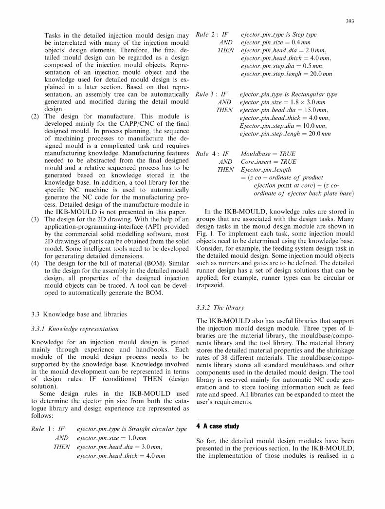
Knowledge for an injection mould design is gainedmainly through experience and handbooks. Eachmodule of the mould design process needs to besupported by the knowledge base. Knowledge involvedin the mould development can be represented in termsof design rules: IF (conditions) THEN (designsolution).
Some design rules in the IKB-MOULD usedto determine the ejector pin size from both the cata-logue library and design experience are represented asfollows:
Rule 1 : IF ejector pin type is Straight circular typeAND ejector pin size ¼ 1:0mm
THEN ejector pin head dia ¼ 3:0mm;ejector pin head thick ¼ 4:0mm
Rule 2 : IF ejector pin type is Step typeAND ejector pin size ¼ 0:4mm
THEN ejector pin head dia ¼ 2:0mm;ejector pin head thick ¼ 4:0mm;ejector pin step dia ¼ 0:5mm;ejector pin step lengh ¼ 20:0mm
Rule 3 : IF ejector pin type is Rectangular typeAND ejector pin size ¼ 1:8� 3:0mm
THEN ejector pin head dia ¼ 15:0mm;ejector pin head thick ¼ 4:0mm;Ejector pin step dia ¼ 10:0mm;ejector pin step lengh ¼ 20:0mm
Rule 4 : IF Mouldbase ¼ TRUEAND Core insert ¼ TRUE
THEN Ejector pin length¼ ðz co� ordinate of product
ejection point at coreÞ � ðz co-ordinate of ejector back plate baseÞ
In the IKB-MOULD, knowledge rules are stored ingroups that are associated with the design tasks. Manydesign tasks in the mould design module are shown inFig. 1. To implement each task, some injection mouldobjects need to be determined using the knowledge base.Consider, for example, the feeding system design task inthe detailed mould design. Some injection mould objectssuch as runners and gates are to be defined. The detailedrunner design has a set of design solutions that can beapplied; for example, runner types can be circular ortrapezoid.
3.3.2 The library
The IKB-MOULD also has useful libraries that supportthe injection mould design module. Three types of li-braries are the material library, the mouldbase/compo-nents library and the tool library. The material librarystores the detailed material properties and the shrinkagerates of 38 different materials. The mouldbase/compo-nents library stores all standard mouldbases and othercomponents used in the detailed mould design. The toollibrary is reserved mainly for automatic NC code gen-eration and to store tooling information such as feedrate and speed. All libraries can be expanded to meet theuser’s requirements.
4 A case study
So far, the detailed mould design modules have beenpresented in the previous section. In the IKB-MOULD,the implementation of those modules is realised in a
393

commercial 3D solid modelling environment—Solid-Designer. SolidDesigner provides a user-friendly API.Using this API, an intelligent and interactive designenvironment for injection mould design is developed.There are many useful menus, tool buttons, dialoguesand commands.
Figure 2 shows a plastic product. With the help of theintelligent and interactive tools provided by the IKB-MOULD, an injection mould is designed to mould thisplastic product.
Mould specification is done during the initial moulddesign. Figure 3 shows the mould specification of thisproduct. The material used is Zenite. Using the materiallibrary, the relative shrinkage rate in three directions isrecommended to reconstruct the product model to ac-count for material shrinkage during the mould opera-tion. Some other mould information, such as the mouldbase, the number of cavities, the mould size, etc., can befound in the mould specification.
The critical design in an injection mould lies in thecore/cavity insert. Due to the complicated structure ofthe product, there are many inserts in the core and thecavity. Figure 4 shows the designed core and cavity in-serts. The designed core inserts with the product are
displayed on the left side and the designed cavity insertsare displayed on the right side of Fig. 4.
Figure 5 shows the final designed mould in the entireIKB-MOULD environment. The left window shows theassembly tree of the injection mould design. Thisassembly tree lists the mould base, inserts (core andcavity inserts), tools (including feeding and coolingsystems) and standard elements (including ejector pins).The assembly tree is automatically generated from theinjection mould objects’ relationship based on the pro-posed object representation. The entire mould can beviewed in whole or in part by selecting the visibilitybutton of each injection mould object in the assemblytree. The final design injection mould base moving half isdisplayed in the current IKB-MOULD environment.The middle window in Fig. 5 shows the designed coreinserts fitted into the standard moving half of the mouldbase plate. The designed cavity inserts are fitted into themould base fixed half. Ongoing work is being performedfor the IKB-MOULD to develop many useful tools thatgenerate 2D engineering drawings from the designedinjection mould. Figure 6 shows the final 2D drawing ofone of the core inserts. Figure 7 shows the assembly 2Ddrawing of the designed mould with the BOM. All 2Ddrawings for the injection mould can be automaticallygenerated based on the designed 3D mould in the IKB-MOULD.
Fig. 7 The assembly 2D drawing
394

5 Conclusions and future work
This paper presents an intelligent and interactive injec-tion mould design system. Based on the analysis of theinjection mould design process, the representation of themould design and the integration of an intelligent andinteractive environment have to be solved to provide abetter injection mould design system. An IKB-MOULDis developed accordingly. The IKB-MOULD integratesthe knowledge representation with many developed toolsin a commercial solid modelling software environment.Such software can speed up the injection mould designprocess and facilitate a design standardisation.
The current version of the IKB-MOULD supportsdesign-for-assembly for the injection mould design. Thisversion only provides the 3D-injection mould design andhas some automation to generate 2D drawings. Tointegrate the CAD/CAM, future work will be focused ondesign-for-manufacture. In other words, the NC code ofthe final injection mould design should be automaticallygenerated.
References
1. Ong SK, Prombanpong S, Lee KS (1995). An object-orientedapproach to computer-aided design of a plastic injectionmould. J Intellig Manufact 6:1–10
2. Ravi B (1997) Intelligent design of gating channels for casting.Mater Sci Technol 13:785–790
3. Wang Z, Lee KS, Fuh JYH et al. (1996) Optimum ejectorsystem design for plastic injection moulds. Int J Comput ApplTechnol 9(4):211–218
4. Britton GA, Tor SB, La YC et al. (2001) Modelling functionaldesign information for injection mould design. Int J Prod Res39(12):2501–2515
5. Costa CA, Young RIM (2001) Product range models sup-porting design knowledge reuse. In: Proceedings of the IM-ECHE, Part B: J Engin Manufact 215(3):323–337
6. Ye XG, Lee KS, Fuh JYH et al. (2001) Automatic initial designof injection mould. Int J Mater Prod Technol 16(6–7):592–604
7. Nielsen EH, Dixon JR, Simmons MK (1986) GERES: Aknowledge based material selection program for injectionmolded resins. Comput Engin ASME 1:255–261
8. Agrawal D, Vasudevan PT (1993) PLASSEX: an expert systemfor plastic selection. Adv Polym Technol 12(4):419–428
9. Chin KS, Wong TN (1996) Knowledge-based evaluation forthe conceptual design development of injection moulding parts.Engin Appl Art Intellig 9(4):359–376
10. Ong SK, Prombanpong S, Lee KS (1995) An object-orientedapproach to computer-aided design of a plastic injectionmould. J Intellig Manufact 6:1–10
11. Cinquegrana DA (1990) Knowledge-based injection moulddesign automation. Disseration, University of Lowell
12. Mok CK, Chin KS, Ho JKL (2001) An interactive knowledge-based CAD system for mould design in injection mouldingprocesses. Int J Adv Manufact Technol 17(1):27–38
13. Tseng AA, Kaplan JD, Arinze OB et al. (1990) Knowledge-based mold design for injection molding processing. In: Pro-ceedings of the 5th International Symposium on IntelligentControl, Philadelphia, PA, September 1990
14. Ravi B, Srinivasan MN (1990) Decision criteria for computer-aided parting surface design. Comput Aid Des 22:11–18
15. Hui KC, Tan ST (1992) Mould design with sweep opera-tions—a heuristic search approach. Comput Aid Des 24(2):81–91
16. Shin KH, Lee K (1993) Design of side cores of the injectionmoulds from automatic detection of interference faces. J DesManufact 3:225–236
17. Hui KC (1997) Geometric aspects of the mouldability of parts.Comput Aid Des 29(3):197–208
18. Chen LL, Chou Sy, Woo TC (1993) Parting directions formould and die design. Comput Aid Des 25(12):762–768
19. Fu MW, Fuh JYH, Nee AYC (1999) Undercut feature recog-nition in an injection mould design system. Comput Aid Des31:777–790
20. Nee AYC, Fu MW, Fuh JYH et al. (1997) Determination ofoptimal parting direction in plastic injection mould design.Annal CIRP 46(1):429–432
21. Fu MW, Fuh JYH, Nee AYC (2001) Core and cavity genera-tion method in injection mould design. Int J Prod Res39(1):121–138
22. Nee AYC, Fu MW, Fuh JYH et al. (1998) Automatic deter-mination of 3-D parting lines and surfaces in plastic injectionmould design. Annal CIRP 47(1):95–98
23. Wong T, Tan ST, Sze WS (1998) Parting line formation byslicing a 3D model. Engin Comput 14:330–343
24. Ye XG, Fuh JY, Lee KS (2000) Automated assembly modellingfor plastic injection moulds. Int J Adv Manufact Technol16(10):739–747
25. Menges G (1986) How to make injection moulds. Hanser,Leipzig
26. Ye XG, Lee KS, Fuh JYH et al. (2001), Automatic initial de-sign of injection mould. Int J Mater Prod Technol 16(6–7):592–604
395