Embed Size (px)
Citation preview
Viscoelastic damping in high rise structures
Appendices
A feasibility study on the development of a prototype toolfor engineering firms which can be used to determine the required amount of viscoelastic damping in a high rise structure to reduce accelerations from wind-induced vibrations to a comfortable level
D.A.J. Hilster

i
COLOPHON
TITLE Viscoelastic damping in high rise structuresSUBTITLE A feasibility study on the development of a prototype tool
to determine the required amount of viscoelastic dampingin a high rise structure to reduce accelerations from wind-induced vibrations
DATE October 2013
AUTHOR D.A.J. (Denise) HilsterPre-education: TU Delft BSc Industrial Design
Bridging program Civil EngineeringCurrent education: TU Delft MSc Civil EngineeringTrack: Building EngineeringSpecialization: Structural Design
CONTACT AUTHOR Pletterijkade 19D2515 SG Den HaagMobile: 06 19 96 11 08E-mail: [email protected]
GRADUATION prof. ir. R. Nijsse (chair)COMMITTEE (Department Building Engineering)TU DELFT prof. dr. A.V. Metrikine
(Department Structural Mechanics)ir. S. Pasterkamp(Department Building Engineering)
CONTACT ir. A. RobbemontZONNEVELD Zonneveld Ingenieurs bvINGENIEURS Delftseplein 27 (floor 8)
3013 AA Rotterdam(010) 452 88 88
CONTACT dr. ir. R.D.J.M. SteenbergenTNO BOUW prof. ir. A.C.W.M Vrouwenvelder& ONDERGROND van Mourik Broekmanweg 6
2628 XE Delft(088) 866 30 00
ii
Viscoelastic damping in high rise structures
A feasibility study on the development of a prototype tool to determine the required amount ofviscoelastic damping in a high rise structure to reduce accelerations from wind-induced vibrations
APPENDICES
Contents
E Definition equivalent stiffness and damping 1E.1 Series and parallel systems . . . . . . . . . . . . . . . . . . . . . . . . . . . . . . . 1E.2 Model of the bracing . . . . . . . . . . . . . . . . . . . . . . . . . . . . . . . . . . 4
E Method to determine matrices 6E.1 Stiffness of the structure . . . . . . . . . . . . . . . . . . . . . . . . . . . . . . . . 6E.2 Rotational stiffness of the foundation . . . . . . . . . . . . . . . . . . . . . . . . . 7
iii

E Definition equivalent stiffness anddamping
E.1 Series and parallel systems
In correspondence with Figure E.1, the equivalent stiffness of parallel connected springs is foundby:
F = Fk1 + Fk2 = k1u+ k2u = (k1 + k2)u (E.1)
The equivalent spring stiffness of springs in series is determined by: [35]
u = u1 + u2 =F1
k1+F2
k2= F
{1
k1+
1
k2
}(E.2)
Figure E.1: Springs in series and parallel and equivalent models
An identical approach can be employed to find the equivalent damping of a system, see FigureE.2. Correspondingly, the equivalent damping of parallel connected dampers is found by:
F = Fc1 + Fc2 = c1u+ c2u = (c1 + c2)u (E.3)
1

2 CHAPTER E. DEFINITION EQUIVALENT STIFFNESS AND DAMPING
Additionally, the equivalent spring stiffness of dampers is expressed by:
du
dt=du1
dt+du2
dt=F1
c1+F2
c2= F
[1
c1+
1
c2
](E.4)
Figure E.2: Springs in series and parallel and equivalent models
In case the system is expressed by a combination of parallel and series elements, the followingprocedure may be followed in accordance with Figure E.3. It must hold that:
F (t) = k3u3(t) + c3u3(t) = k2u2(t) + c2u2(t) = k1u1(t) + c1u1(t)
=
(k3 + c3
d
dt
)u3(t) =
(k2 + c2
d
dt
)u2(t) =
(k1 + c1
d
dt
)u1(t)
(E.5)
In this case, an equivalent stiffness cannot be found due to the time dependency of the damping.Therefore, an operator is now introduced instead:
O =1
1k3+c3
ddt
+ 1k2+c2
ddt
+ 1k1+c1
ddt
(E.6)

E.1. SERIES AND PARALLEL SYSTEMS 3
Figure E.3: Springs and dampers in a combination of series and parallel and equivalent models
In the frequency domain the above equations are expressed by:
F (ω) = (k3 + iωc3)︸ ︷︷ ︸k∗3
u3(ω) = (k2 + iωc2)︸ ︷︷ ︸k∗2
u2(ω) = (k1 + iωc1)︸ ︷︷ ︸k∗1
u1(ω) (E.7)
And:
O =1
1k∗3
+ 1k∗2
+ 1k∗1
(E.8)
A similar procedure can be used in case one element is not present in comparison with FigureE.3. For example, in Figure E.4 the spring in element 2 is not present and thus:
F =
(k3 + c3
d
dt
)u3(t) = c2
d
dtu2(t) =
(k1 + c1
d
dt
)u1(t) (E.9)
And correspondingly:
O =1
1k3+c3
ddt
+ 1c2
ddt
+ 1k1+c1
ddt
(E.10)
In the frequency domain the above equations are expressed by:
F (ω) = (k3 + iωc3)︸ ︷︷ ︸k∗3
u3(ω) = iωc2︸︷︷︸k∗2
u2(ω) = (k1 + iωc1)︸ ︷︷ ︸k∗1
u1(ω) (E.11)
And:
keq =1
1k∗3
+ 1k∗2
+ 1k∗1
(E.12)

4 CHAPTER E. DEFINITION EQUIVALENT STIFFNESS AND DAMPING
Figure E.4: Springs and dampers in a combination of series and parallel and equivalent models
E.2 Model of the bracing
In correspondence with Figure E.5, the equivalent stiffness of the bracing in the frame is calcu-lated by:
F = ku
ε =N
EA=
∆l
l−→ N = ∆l
EA
l∆l = u cosα
= ub√
b2 + h2
F = N cosα
= Nb√
b2 + h2
=EA
l∆l
b√b2 + h2
=
[EA
l
b√b2 + h2
b√b2 + h2
]u
=
[EA√b2 + h2
b√b2 + h2
b√b2 + h2
]u
=
[b2
{b2 + h2}3/2EA
]︸ ︷︷ ︸
stiffness bracing
u
(E.13)
E.2. MODEL OF THE BRACING 5
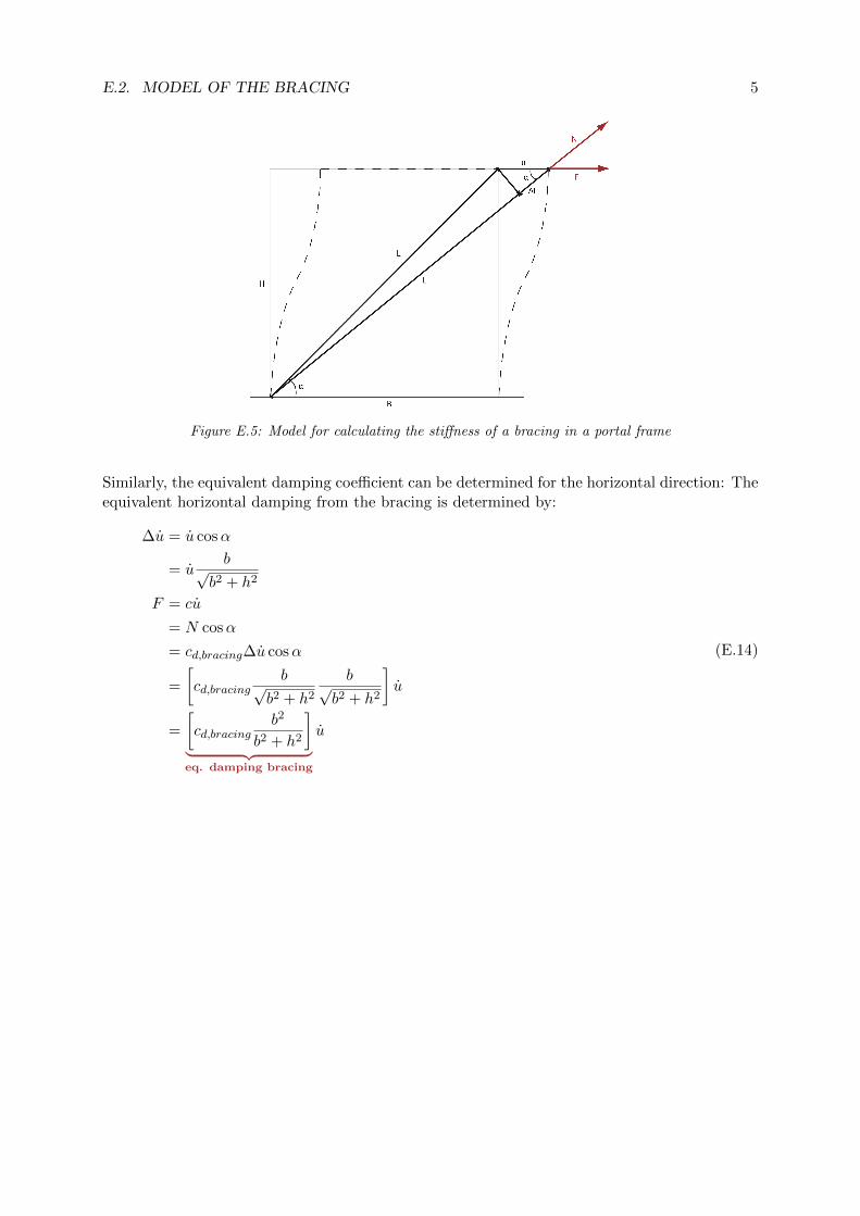
Figure E.5: Model for calculating the stiffness of a bracing in a portal frame
Similarly, the equivalent damping coefficient can be determined for the horizontal direction: Theequivalent horizontal damping from the bracing is determined by:
∆u = u cosα
= ub√
b2 + h2
F = cu
= N cosα
= cd,bracing∆u cosα
=
[cd,bracing
b√b2 + h2
b√b2 + h2
]u
=
[cd,bracing
b2
b2 + h2
]︸ ︷︷ ︸eq. damping bracing
u
(E.14)

E Method to determine matrices
E.1 Stiffness of the structure
The stiffness is determined in accordance with Figure E.1. The stiffness of the springs is ex-pressed by: [6;7]
M = Ke (E.1)
Figure E.1: Model to determine the stiffness of the core structure
The rotations are described by:
φij =1
h(wj − wi) (E.2a)
φjk =1
h(wk − wj) (E.2b)
Correspondingly:
e = φij − φjk =1
h(−wi + 2wj − wk) (E.3)
And thus:
M = Ke =K
h(−wi + 2wj − wk) (E.4)
6

E.2. ROTATIONAL STIFFNESS OF THE FOUNDATION 7
Then, the forces are:
Fi = −Mh
=K
h2(−wi + 2wj − wk) (E.5a)
Fj = 2M
h=K
h2(−2wi + 4wj − 2wk) (E.5b)
Fk = −Mh
=K
h2(−wi + 2wj − wk) (E.5c)
And in matrix notation:Fi
Fj
Fk
=K
h2
1 −2 1−2 4 −21 −2 1
wi
wj
wk
(E.6)
E.2 Rotational stiffness of the foundation
In correspondence to Figure E.9 the rotational stiffness of a foundation is to be determined by:
Kr =M
θ(E.7)
Correspondingly, the following applies:
Figure E.2: Model to determine the rotational stiffness of a foundation
θ =u
hstorey
M = Krθ = Kru
hstorey
F =M
hstorey=
(Kr
h2storey
)u
(E.8)
The corresponding n x n stiffness matrix becomes:
Kfoundation =
k11
. . .. . .
. . .. . .
. . . knn
=
Kr
h2storey
· · · 0
.... . .
...0 · · · 0
(E.9)

8 CHAPTER E. METHOD TO DETERMINE MATRICES
The normal force in the piles is to be calculated by:
M = Fhstorey = Npile2a (E.10a)
Npile =Fhstorey
2a(E.10b)
The rotation θ of the foundation is to be found by:
εpile =Npile
(EA)pile= Lpile∆Lpile
∆Lpile =Npile
Lpile(EA)pile
θ = tan−1
{∆Lpile
a
} (E.11)
Hence, the rotational stiffness Kr becomes:
Kr =Fhstorey
tan−1{
∆Lpile
a
} (E.12)

Bibliography
[1] Ali M.M., Moon K.S., 2007, Structural Developments in Tall Buildings: CurrentTrends and Future Prospects, university of Sydney
[2] Aquino R.E.R., Tamura Y., 2013, On stickslip phenomenon as primary mechanismbehind structural damping in wind-resistant design applications, Journal of WindEngineering and Industrial Aerodynamics vol.115 p.121-136
[3] Berg R.L.J. van den, 2012Investigation of damping in high-rise building, TU Delft
[4] Bilbao A., Avils R., Agirrebeita J., Ajuria G., 2005, Proportional damping approx-imation for structures with added viscoelastic dampers, Finite elements in analysisand design 42
[5] Blaauwendraad prof. dr. ir. J., 2005, Dynamica van systemen, TU Delft, page43-44
[6] Blaauwendraad prof. dr. ir. J., 2006,Plate analysis, theory and application, volume2 numerical methods, TU Delft
[7] Breen H., 2007, Tall storeys: active control of wind impact on high-rise buildings,TU Delft
[8] Callister W.D.Jr, 2003, Materials science and engineering - An introduction, JohnWiley and Sons
[9] Cook N.J., 1985 The designers guide to wind loading of building structures, TheUniversity Press Cambridge
[10] eFluids.com, http://www.princeton.edu/ asmits/Bicycle
web/Bernoulli.html(Accessedatfebruary21nd2013), P rincetonUnversity
[11] http://www.emporis.com/statistics/worlds-tallest-buildings (checked at novem-ber 29 2012)
[12] Hoenderkamp J.C.D., 2007, High-rise structures, preliminary design for lateralload, Eindhoven Univerisity of Technology, chapter 2 and 3
[13] Holmes J.D., 2001, Wind loading of structures, Taylor & Francis
[14] Hoorn H., year unknown, Vergrotingsfactoren Zalmhaven DO fase aangepast, Zon-neveld Ingenieurs
[15] Horr A.M., Schmidt L.C., 1996, Modelling of nonlinear damping characteristicsof a viscoelastic structural damper, Engineering Structures vol.18 no.2 pp.154-161
[16] Jeary A.P, 1981, The dynamic behaviour of tall buildings, University College Lon-don
9
10 BIBLIOGRAPHY
[17] Jones D.I.G., 2001, Handbook of viscoelastic vibration damping, John Wiley &Sons Ltd.
[18] Kareem A., Kijewski T., Tamura Y., 1999, Mitigations of motions of tall buildingswith specific examples of recent applications, Wind and structures vol. 2 no. 3, page201-239
[19] Kuroda H., Arima F., Baba K., Inoue Y., 2000, Principles and characteristicsof viscous damping devices (gyro-damper), the damping forces which are highlyamplified by converting the axial movement to rotary one, 12th world conferenceon earthquake engineering
[20] Lai M.L., Lu P., Lunsford., Kasai K., Chang K.C., 1996, Viscoelastic damper: adamper with linear or nonlinear material?, Elsevier Science Ltd.
[21] Li Q.S., Yang K., Zhang N., Wong C.K., Jeary A.P., 2002, Field measurementsof amplitude-dependent damping ga 79-storey tall building and its effect on thestructural dynamic responses, Structural design tall buildings no. 11, Whiley In-terScience
[22] Lohnert G., Dalkowski A., Sutter W., 2003, Integrated design process - A guidelinefor sustainable and solar-optimised building design, International Energy Agency
[23] Lu L., Chung L.,Wu L.,Li G., 2004, Dynamic analysis of structures with frictiondevices using discrete-time state-space formulation, Computers and structures,page 1049-1052
[24] Lythe G.R., Surry D., 1990 Wind-Induced Torsional Loads on Tall Buildings,Journal of Wind Engineering and Industrial Areodynamics, no. 36, page 225-234
[25] Marui E., Endo H., Hashimoto M., Kato S., 1996, Some considerations of slidewayfriction characteristics by observing stick-slip vibration, Tribology Internationalvol. 29 no. 3 pp. 251-262, Elsevier Science ltd
[26] Metrikine A.V., year unknown, Slender Structures and Introduction to Continuummechanics; Module: Dynamics of Mechanical Systems and Slender Structures:Lecture Notes CT 4145, TU Delft
[27] NASA, year unknown, URL: http://www.grc.nasa.gov/WWW/BGH (Accessed atfebruary 25th 2013), NASA
[28] Nemetschek Scia nv, 2011, Advanced Professional Training - Dynamics, Scia En-gineer
[29] NEN, 2011, National Annex to NEN-EN 1991-1-4+A1+C2: Eurocode 1: Ac-tions on structures - Part 1-4: General actions - Wind actions, NederlandsNormalisatie-instituut
[30] NEN, 2011, National Annex to NEN-EN 1990+A1+A1/C2-2011: Eurocode 1:Basis of structural design, Nederlands Normalisatie-instituut
[31] Nijsse prof. R., 2012, Lecture slides Buildings Structures II (guest lecture), DelftUniversity of technology
[32] Oosterhout G.P.C. van, 1996, Wind-induced dynamic behaviour of tall buildings,TU Delft

BIBLIOGRAPHY 11
[33] Pasquin C., Leboeuf N., Pall R.T., Pall A., 2004, Friction dampers for seismicrehabilitation of Faton’s building, Montreal, 13th world conference on earthquakeengineering, page 1-2
[34] Robbemont A.J., 1995, The dynamic behaviour of tall buildings as a design cri-terion, TU Delft
[35] Simone A., 2011, An Introduction to the Analysis of Slender Structures, TU Delft,ch. 2-3
[36] Skyscraper Group, 2011, URL: www.skyscraper.com (Accessed at december 152012), Skyscraper group
[37] Smith B.S, Coull A., 1991, Tall Building Structures — Analysis and Design, JohnWiley & Sons Inc., page 1
[38] Smith R.J., Willford M.R., 2007, The damped outrigger concept for tall buildings,John Wiley & Sons
[39] Spijkers J.M.J, Vrouwenvelder A.W.C.M., Klaver E.C., 2005, Dynamics of struc-tures part 1 vibration of structures, TU Delft
[40] Steenbergen R.D.J.M., 2007, Super Elements in High-Rise Buildings underStochastic Wind Load, TU Delft
[41] TA Instruments, 1998, Energy storage and dissipation in viscoelastic materials,TA Instruments
[42] Thorne K, year unknown, URL: http://www.pma.caltech.edu/Courses/ph136/yr2004/book03/chap05/0205.1.pdf (Accessed at december 2nd 2012), California In-stitute of Technology
[43] Vrouwenvelder A.W.C.N, 2004, Random vibrations, TU Delft
[44] Vuik C., Beek P. van, Vermolen F., Kan J. van, 2006, Numerieke methoden voordifferentiaalvergelijkingen, VSSD, chapter 6
[45] Wang J., Jin F., Zhang C., 2011, Estimation error of the half-power bandwidthmethod in identifying damping for multi-DOF systems, Tsinghua University, Bei-jing
[46] Yu C., Roesset J.M., 2001, Dynamic stiffness matrices for linear members withdistributed mass, Tamkang Journal of Science and Engineering, Vol. 4, No. 4, pp.253-264
[47] Zegers S.F.A.J.G., 2011, Lightweight floor system for vibration comfort, Eind-hoven University Press Facilities

Graduation committee:prof. ir. R. Nijsse (chair, TU Delft)prof. dr. A.V. Metrikine (TU Delft)ir. S. Pasterkamp (TU Delft)dr. ir. R.D.J.M. Steenbergen (TNO)prof. ir. A.C.W.M Vrouwenvelder (TNO)ir. A. Robbemont (Zonneveld Ingenieurs)ir. A. Robbemont (Zonneveld Ingenieurs)


![METRO Next Vision v11 07252018 FINAL · %xv 2shudwlrqv 2swlpl]hg 6\vwhp 7uhdwphqwv ¾,psuryhv vshhg dqg uholdelolw\ rq kljk iuhtxhqf\ kljk ulghuvkls exv urxwhv ¾7rroer[ lqfoxghv](https://img.dokumen.tips/doc/110x75/5be94cc909d3f2200d8c08be/metro-next-vision-v11-07252018-xv-2shudwlrqv-2swlplhg-6vwhp-7uhdwphqwv-psuryhv.jpg)