Embed Size (px)
Citation preview

9.801-509.0 - C11/02/17
OPERATOR’S MANUAL
To locate your local Kärcher Commercial Pressure Washer Dealer nearest you,visit www.karchercommercial.com
■ HDS3.5/20 ■ HDS4.0/22 ■ HDS3.9/30 ■ HDS5.0/23 ■ HDS4.8/30 ■ HDS6.3/32 ■ HDS8.0/32 ■ HDS9.5/30
LISTED ®
98015080-1
GROUND
8
10
12
1416
0
2
46
TACH/HOUR
TACH/HOUR
1. Place all switches in the “O
FF” positio
n.
2. Connect power s
upply to properly grounded outlet. T
est
the GFCI (if
equipped) using the re
set and test procedures
provided on the GFCI device. The GFCI must be re
set and
tested with every use.
3. Secure high pressure hose, shut-off g
un and wand to out-
let
4. Connect water supply hose and turn on water.
5. Grasp wand
Place pump switch in the “O
N” position.
6. Turn gas valve
control knob to
“ON” p
osition. P
ilot will l
ight
automatically when burner switch is turned “O
N”.
7. To heat water, p
lace burner switch in the “O
N” position and
adjust therm
ostat to desired temperature.
8. Turn on detergent and proceed with cleaning.
9. After cleaning:
A. Turn off d
etergent and rinse.
B. Place burner sw
itch in the “OFF” p
osition.
C. A
llow machine to discharge water for 2
-3 minutes to
cool coil.
D. Place pump sw
itch in the “OFF” p
osition.
E. S
queeze trigger g
un to relieve system pressure.
F.
Turn off water supply.
MODE D’EMPLOI
LIRE LE MANUEL DE L’OPERATEUR AVANT UTILISATION UNE
MAUVAISE UTILISATION PEUT CAUSER DES BLESSURES OU
DOMMAGES MATÉRIELS.
INSTRUCCIONES DE OPERACION
LEA EL MANUAL DE OPERACIÓN ANTES DE USARSE. LA OPERACIÓN
INADECUADA PUEDE OCASIONAR LESIONES PERSONALES O DAÑOS
A LAS PROPIEDADES.
OPERATING INSTRUCTIONS
READ OPERATING MANUAL BEFORE OPERATING MACHINE.
IMPROPER OPERATION MAY RESULT IN PERSONAL IN
JURY OR
PROPERTY DAMAGE.
1. Coloque todos los interruptores en la posición “O
FF” (APAGADO).
2. Conecte la fuente de energía a un tomacorriente conectado a tie
rra de modo ad-
ecuado. Pruebe el In
terruptor A
ccionado por Corrie
nte de Pérdida a Tierra (G
FCI
por sus siglas en In
glés) (si h
ubiera) mediante lo
s procedimientos de reinicio y
prueba incorporados en dicho dispositivo. E
l GFCI d
ebe reiniciarse y ponerse a
prueba cada vez que se use.
3. Asegure la manguera de alta presión, p
istola y varilla
al acoplador del to
macor-
riente.
4. Conecte la manguera de suministro de agua y abra la lla
ve.
5. Sujete
la va
rilla. C
oloque el interru
ptor de la
bomba en la posición
“ON” (ENCENDIDO).
6. Coloque la perilla de contro
l de la válvula de gas en la posición “ON” (E
NCENDI-
DO). El piloto se encenderá automáticamente cuando el quemador se encienda.
7. A de calentar e
l agua, coloque el interru
ptor del quemador e
n la posición “ON”
(ENCENDIDO) y ajuste el term
ostato a la temperatura deseada.
8. Encienda el detergente y proceda con la limpieza.
9. Después de limpiar:
A. Apague el detergente y enjuague.
B. Ponga el in
terruptor d
el quemador en la posición “O
FF” (APAGADO).
C. Deje que la máquina descargue agua por 2
ó 3 minutos para que se
enfríe el serpentín.
D. Ponga el in
terruptor d
e la bomba en la posición “OFF” (A
PAGADO).
E. Presione la pistola para aliviar la
presión del sistema.
F.
Cierre el suministro
de agua.
1. Mettez tous les interrupteurs en positio
n “OFF”.
2. Connectez le bloc d’alimentation électriq
ue à une prise correctement
mise à la terre. Testez le disjoncteur d
e fuite de terre (le
cas échéant)
à l’aide des procédures de ré
initialisation et d
’essai indiquées sur le
disjoncteur. Le disjoncteur d
oit être
réinitia
lisé et testé à chaque utili-
sation.
3. Fixez le tuyau à haute pression, le
pistolet et le tube rig
ide au raccord
de sortie.
4. Connectez le tuyau à eau et faites couler l’e
au.
5. Tenez le tube rig
ide fermement. M
ettez l’interru
pteur de la pompe en
position “O
N”.
6. Tournez le bouton du ro
binet de gaz en positio
n “ON”.
La veille
use
s’allume automatiquement lorsque l’in
terrupteur du brûleur est m
is sur
“ON”.
7. Pour chauffer l’eau, m
ettez l’interru
pteur du brûleur sur “O
N” et réglez
le thermostat à la température vo
ulue.
8. Activez le détergent et commencez le nettoyage.
9. Après le nettoyage :
A. Coupez le détergent et ri
ncez.
B. Mettez l’in
terrupteur d
u brûleur sur “OFF”.
C. Laissez la machine évacuer l’e
au pendant 2 à 3 minutes, le
temps que la bobine refro
idisse.
D. Mettez l’in
terrupteur d
e la pompe sur “OFF”.
E. Actionnez le pistolet pour ré
duire la pression du système.
F.
Coupez l’eau.
WARNING
PRECAUCION / AVERTISSEMENT
TO REDUCE THE RISK
OF INJURY READ
OPERATOR’S MANUAL
CAREFULLY BEFORE
USING. THIS MACHINE
TO BE USED ONLY BY
QUALIFIED OPERATORS.
LEA EL MANUAL OPERACION ANTES
DE USARSE. ESTE EQUIPO DEBE SER
USADO SOLAMENTE POR OPERA-
DORES CALIFICADOS.
LIRE LE MANUEL DE L’OPERATEUR
AVANT UTILISATION. CET APPAREIL
DOIT ETRE UTILISE PAR DES OPERA-
TEURS QUALIFIES.
RISK OF INJURY—
PROTECTIVE EYE-
WEAR AND CLOTHING
MUST BE WORN.
when operating this
machine.
PROTEJASE LOS OJOS CU-
ANDO se opere este equipo.
DES LUNETTES DE SECURITE
DOIVENT ETRE PORTEES
lorsque vous operez cet a
ppareil.
RISK OF
ASPHYXIATION. Use
only in well venti-
lated area.
RIESGO DE ASFIXIA. Use el
producto en un area de venti-
lación adecuada.
RISQUE D’ASPHYXIE. Utilis
er
dans un endroit bien aéré.
RISK OF
ELECTROCUTION. Connect o
nly to
properly grounded outlet. Keep all c
on-
nections dry and off the ground. K
eep
spray away from electric
al wirin
g and
components. Disconnect fr
om electrical
supply before servicing.
RIESGO DE ELECTROCUCIÓN — Co-
necte el enchufe en un contacto adecuado.
Mantenga todas las connecciones secas
y arriba del suelo. N
o rocie componentes
eléctricos. D
esconecte la
corriente eléctric
a antes de
dar servicio.
RISQUE
D’ELECTROCUTION
— Relier à
des prises avec
mise à la terre
seulement.
Tous les doive
nt être
maintenus secs et étre
sus-
pendus. No jamais projeter
de l’eau sur le
s com-
posantes et électriq
ues.
Couper l’alim
entatation
électrique avant d
e faire une
réparation.
RISK OF INJECTION OR SE-
VERE INJURY TO PERSONS.
Keep clear of n
ozzle.
HOT DISCHARGE FLUID —Do
not touch or d
irect d
ischarge
stream at p
ersons.
RIESGO DE PENETRACIÓN O
LESIONES SEVERAS A PERSO-
NAS. Manténgase fu
era del alcance
de boquilla.
DESCARGA DE AGUA CALIENTE
A ALTA PRESION — No to
que
ni dirija el
del agua a otras
personas.
RISQUE DE BLESSURES. Se te
nir
loin des buses.
EAU CHAUDE SOUS PRESSION A
LA SORTIE — Ne pas dirig
er le jet
d’eau vers des personnes.
SPRAY GUN KICKS BACK
— Hold with both hands.
LA PISTOLA SE MUEVE CON
LA PRESIÓN — Sostenga con las
dos manos.
LA POIGNEE PISTOLET RE-
POUSSE — Tenir à
deux mains.RISK OF IN
JURY—HOT
SURFACES CAN CAUSE
BURNS — Use only
designed gripping areas of
spray gun and wand.
SUPERFICIES CALIENTES
— Use solamente las áreas
aisladas del gatillo y la lanza.
SURFACES CHAUDES —
Toucher seulement le
s parties
isolées des poignée pistolets
et lances.
RIESGO DE EXPLOSION — Use
el producto en áreas donde el fuego
o llama sean perm
itidos. N
o rocie
liquidos
RISQUE D’EXPLOSION — Utilis
er
aux endroits où une
nue est
permise. N
e pas vaporiser d
e liquides
RISK OF
EXPLOSION. Operate only
where open
or torch is perm
itted.
Do not spray
liquids.
RISQUE DE FEU OU D’EXPLOSION
RIESGO DE INCENDIO O EXPLOSIÓN
RISK OF FIRE OR EXPLOSION
• Machine needs to
be installed on non-combustib
le
with minimum clearance of 18”.
Before lig
hting, smell a
ll around th
e appliance area for
gas. Be sure to smell next to
the because some gas
is heavier than air a
nd will settle
on the If y
ou smell
gas, immediately call y
our gas supplier for in
structions. If
gas supplier can not be reached, call the
department.
Do not use tools to push in or tu
rn the gas control knob.
If knob will n
ot push in or tu
rn by hand, call a
service technician. Using force or a
ttempting re
pair may
result in a
or explosion.
Should pilot o
utage occur, turn contro
l knob to
OFF
position. W
ait 5 m
inutes before relighting.
Do not u
se this equipment if
any part has been under
water. Immediately call a
service technician to
inspect
for repair.
El equipo debe ser in
stalado sobre un piso resistente
al incendio, con un espacio lib
re de 18” minimo.
Antes de encender, o
lfatee alrededor d
el aparato para
detectar gas. E
sté seguro de revisar c
erca del piso,
porque ciertos gases son m
ás pesados que el aire. S
i
olfatea gas, avise in
mediatamente a su proveedor de
gas. Al no localizar el proveedor, llame a los bomberos.
No use herra
mientas para mover e
l contro
l del g
as.
Si la m
anija no se puede operar con la m
ano, llame a
un técnico capacitado. F
orzar o in
tentar reparar e
ste
control puede re
sultar en un incendio o explosión.
En el caso de apagarse el p
iloto, apague y espere 5
minutos antes de encender.
No utilic
e este equipo en el caso que hubiera estado
sumergido en agua parcial o to
talmente un compo-
nente. Consulte con un té
cnico de servicio.
Ne pas in
staller ce m
achine aux endroits où il y a des
combustibles (même les plancher) d
edans un demi-mètre
.
Avant l’
allumage,
autour de l’a
ppareil pour d
es
senteurs de gaz.
les odeurs près du plancher car
certains gaz sont plus lourds que l’a
ir et s’accumulent sur
le plancher. Si vo
us détectez une odeur de gaz, a
ppelez
immédiatement votre
fournisseur d
e gaz. Si c
elui-ci ne
peut être
joint, appeler le
département d
es incendies.
Ne pas utilis
er d’outils pour pousser ou tourner la
soupape
de contrôle du gaz. Si la
soupape ne peut être enfoncée ou
tournée à la main, appeler un technicien
Forcer ou
essayer de ré
parer peut causer u
n feu ou une explosion.
Si le
pilote s’éteint, tourner la
soupape de contrôle en
position OFF. A
ttendre 5 m
inutes avant de ré
allumer.
Ne pas utilis
er cet équipement si une partie a été im
mergée
dans l’eau. A
ppeler un te
chnicien pour inspecter c
elui-ci.
8.900-990.0
CHAUD!
WARNING:This product and accessories may contain a chemical known to the State of California to cause cancer and birth defects or other reproductive harm.
For more information about this regulation: www.P65Warnings.ca.gov

9.801-509.0 - C • Karcher Operator's Manual
SYMBOLS
Pump Switch
Detergent
Steam Combination
Hour Meter
Motor OverloadWhen the light is on, it means the overload is tripped.Reset overload.
Pilot LightWhen the light is on, it means there is power to the pilot control. If there is no light, see troubleshooting guide.
VoltageWhen the light is on, it means power supply is on
Burner Switch
Not all machines have all symbols
Identifi cation of Operational Label Symbols

3
CONTENTS
9.801-509.0 - C • Karcher Operator's Manual
Identifi cation of Operational Label Symbols 2
Introduction & Safety Information 4-6
Component Identifi cation-All Models 7
Installation HDS 3.5/20, 4.0/22, 3.9/30, 5.0/23, 4.8/30 8
Installation HDS 6.3/32, 8.0/32, 9.5/30 19
Installation 10-16
Assembly Instructions 17
Operating Instructions 18
Applying Detergent & General Washing Techniques 19
Shutting Down & Cleanup 20
Storage 20
Troubleshooting 21-24
Maintenance & Service 25
Heating Coils 25
Propane Gas 16
Burner Features 26-27
Basic Facts and Equivalents 28
Equivalents and Oil Change 29
Preventive Maintenance 30

9.801-509.0 - C • Karcher Operator's Manual
MA
NU
AL
PR
ES
SU
RE
WA
SH
ER
4
INTRODUCTION & IMPORTANT SAFETY INFORMATION
Thank you for purchasing this Pressure Washer.We reserve the right to make changes at any time without incurring any obligation.
Owner/User Responsibility:The owner and/or user must have an understand-ing of the manufacturer’s operating instructions and warnings before using this pressure washer. Warning information should be emphasized and understood. If the operator is not fl uent in English, the manufac-turer’s instructions and warnings shall be read to and discussed with the operator in the operator’s native language by the purchaser/owner, making sure that the operator comprehends its contents.
Owner and/or user must study and maintain for future reference the manufacturers’ instructions.
The operator must know how to stop the machine quickly and understand the operation of all controls. Never permit anyone to operate the engine without proper instructions.
SAVE THESE INSTRUCTIONS
This manual should be considered a permanent part of the machine and should remain with it if machine is resold.
When ordering parts, please specify model andserial number. Use only identical replacement parts.
This machine is to be used only by trained operators.
IMPORTANT SAFETY INFORMATION
WARNING: If you do not follow these instructions exactly, a fi re or explosion may result, causing property damage, personal injury or loss of life.
WARNING: To reduce the risk of injury, read operating instruc-tions carefully before using.
1. Read the owner's manual thoroughly. Failure to follow instructions and warnings could cause malfunction of the machine and result in death, serious bodily injury and/or property damage.
2. Know how to stop the machine and bleed pressure quickly. Be thoroughly familiar with the controls.
3. Stay alert — watch what you are doing.
4. Use only your hand to push in or turn the gas control knob. Never use a tool. If the knob will not push in or turn by hand, don't try to repair it; call a qualifi ed service technician.
READ OPERATOR’S MANUAL THOROUGHLY
PRIOR TO USE.
5. All installations must comply with local codes. Contact your electrician, plumber, utility company or the selling distributor for specifi c details.
DANGER: Improper connection of the equipment-grounding conductor can result in a risk of electro-cution. Check with a qualifi ed electrician or service personnel if you are in doubt as to whether the outlet is properly grounded.
WARNING: Keep wand, hose, and water spray away from electric wiring or fatal electric shock may result.
6. To protect the operator from electrical shock, the machine must be electrically ground-ed. It is the responsibility of the owner to connect this
machine to a grounded receptacle of proper voltage and amperage ratings. Do not spray water on or near electr ical components. Do not touch machine with wet hands or while standing in water. Always disconnect power before servicing.
RISK OF EXPLOSION: IF GAS SMELL
PRESENT TURN OFF SUPPLY
WARNING WARNING: Flammable liquids can create fumes which can ignite, causing property dam-age or severe injury.
WARNING: Risk of explosion — Operate only where open fl ame or torch is permitted. Do not spray fl ammable liquids.
RISK OF FIRE. DO NOT ADD FUEL WHEN OPERATING
MACHINE.
WARNING WARNING: Risk of fi re — Do not change LP tanks when the product is operating or still hot.
WARNING: Use vapor fuel only.
7. Gas appliances shall be installed only in locations where combustible dusts and fl ammable gases or vapors are not present. Do not store or use gasoline near this machine.
WARNING: In the event of a pilot outage, wait at least fi ve minutes to clear out any gas before relighting.
8. Keep operating area clear of all persons.
WARNING
KEEP WATERSPRAY AWAY FROM
ELECTRICAL WIRING.

9.801-509.0 - C • Karcher Operator's Manual5
PR
ES
SU
RE
WA
SH
ER
MA
N U
AL
IMPORTANT SAFETY INFORMATION
WARNING
USE PROTECTIVE EYE WEAR
AND CLOTHING WHEN OPERATINGTHIS EQUIPMENT.
WARNING: High pressure spray can cause paint chips or other particles to become airborne and fl y at high speeds. To avoid personal injury, eye, hand and foot safety devices must be worn.
9. Eye, hand, and foot protec-tion must be worn when using this equipment.
WARNING
EAR PROTECTION MUST BE WORN
WARNING: This machine ex-ceeds 85 db appropriate ear protection must be worn.
WARNING
RISK OF INJURY. HOT SURFACES
CAN CAUSE BURNS
WARNING: Risk of injury. Hot surfaces can cause burns. Use only designated gripping areas of spray gun and wand. Do not place hands or feet on non-in-sulated areas of the pressure washer.
10. To reduce risk of injury, close supervision is neces-
sary when a machine is used near children. Do not allow children to operate pressure washer. This machine must be attended during operation.
TRIGGER GUN KICKS BACK - HOLD WITH
BOTH HANDS
WARNING WARNING: Grip cleaning wand securely with both hands be-fore starting. Failure to do this could result in injury from a whipping wand.
11. Never make adjustments on machine while in operation.
12. Be certain all quick coupler fi ttings are secured before using pressure washer.
RISK OF INJECTION OR SEVERE INJURY TO PERSONS. KEEP CLEAR OF NOZZLE.
WARNING WARNING: High pressure de-veloped by these machines will cause personal injury or equip-ment damage. Keep clear of nozzle. Use caution when op-erating. Do not direct discharge stream at people, or severe injury or death will result.
WARNING
PROTECT FROM FREEZING
WARNING: Protect machine from freezing.
13. To keep machine in best operating conditions, it is important you protect machine from freezing. Failure to protect machine f rom freezing could cause malfunction of the machine and result in death,
serious bodily injury, and/or property damage. Fol-low storage instructions specifi ed in this manual.
WARNING
RISK OFASPHYXIATION. USE THIS PRODUCT ONLY
IN A WELLVENTILATED AREA.
WARNING: Risk of asphyxiation. Use this product only in a well ventilated area.
14. Avoid installing machines in small areas or near exhaust fans. Adequate oxygen is needed for combustion or dangerous carbon monoxide will result.
15. Manufacturer will not be liable for any changes made to our standard machines or any compo-nents not purchased from us.
16. The best insurance against an accident is precau-tion and knowledge of the machine.
WARNING
RISK OF INJURY FROM FALLS WHEN
USING LADDER.
WARNING: Be extremely careful when using a ladder, scaffold-ing or any other relatively un-stable location. The cleaning area should have adequate slopes and drainage to reduce the possibility of a fall due to slippery surfaces.
17. Do not overreach or stand on unstable support. Keep good footing and balance at all times.
18. Do not operate this machine when fatigued or under the infl uence of alcohol, prescription medi-cations, or drugs.
19. Follow the maintenance instructions specifi ed in the manual.
WARNING: Use vapor fuel only.
20. The LP models are designed to run on vapor pro-pane fuel. Do not use liquid fuel. Have a qualifi ed serviceman install and service your equipment.
21. Never expose a spark or fl ame where there may be unburned gas present.

9.801-509.0 - C • Karcher Operator's Manual
MA
NU
AL
PR
ES
SU
RE
WA
SH
ER
6
IMPORTANT SAFETY INFORMATION
22. Install optional LP gas regulator assembly, item
9.802-633.0 or obtain a proper size regulator.
23. Install this machine about 2 feet from wall to provide adequate ventilation and servicing space. This equipment incorporates parts such as snap switches or similar parts that tend to produce arcs or sparks. Therefore, when located in a garage, it should be in a room or enclosure provided for the purpose or should be installed 18" (457mm) or more above the fl oor.
WARNING: To reduce the risk of electric shock, disconnect all electrical connections and shut-off gas valve before servicing.
24. Install this machine on non combustible fl ooring.
25. Do not allow acids, caustic or abrasive fl uids to pass through the pump.
26. Never run pump dry or leave spray gun closed longer than 3 minutes.
WARNING: If connection is made to potable water supply, a back fl ow device must be provided.
27. Exhaust gases should not be vented into a wall, a ceiling or a concealed space of a building. A draft diverter must be installed to prevent down draft and to allow cooling of exhaust temperatures. Down draft diverters shall be installed in the
vents and located at a dis-tance from the pressure wash-er stack to achieve maximum draft of 36" minimum. Exhaust gases that exceed 470°F (243°C) are not suitable for connection to Type B gas vents.
Example of Down Draft Diverter for Gas Fired Machines
Follow the maintenance instructions specifi ed in the manual.
ITEM PART NO. DESCRIPTION QTY 9.802-633.0 Regulator, LP Assembly 1
1 9.802-019.0 Nipple, 3/4" x 2", Black 1
2 8.717-747.0 Regulator, R622CFF for R932/28 & R932462 1
3 8.717-746.0 Regulator, Hi Pressure, R321H22 1
4 8.711-855.0 Hose, 1/2" x 19", Propane 1
5 8.717-782.0 Fitting, Pigtail, Fisher, M318 (Included when ordering part 8.717-746.0) 1
98015100-48
To Propane
Bottle
To Pressure Washer
Gas Inlet
1
3
5
2
4
Optional Regulator Kit9.802-633.0

9.801-509.0 - C • Karcher Operator's Manual7
PR
ES
SU
RE
WA
SH
ER
MA
N U
AL
COMPONENT IDENTIFICATION - ALL MODELS
Pump — Delivers a specifi c gpm to the high pressure nozzle which develops pressure. (Not Shown)
Spray Gun — Controls the application of water and de ter gent onto cleaning surface with trigger device. In cludes safe ty latch.
Detergent Valve— Allows you to siphon and mix de ter gents.
Wand — Must be connected to the spray gun.
High Pressure Hose — Connect one end to water pump high pressure discharge nipple and the other end to spray gun.
Rupture Disk — Secondary pressure release in the unlikely event the unloader valve fails. (Not Shown)
Unloader Valve — Safety device which, when the spray gun closes, prevents over pressurization. (Not Shown)
NOTE: If trigger on spray gun is released for more than 3 minutes, water will leak from the pump pro tec tor. Warm wa ter will dis charge from pump pro tec tor onto fl oor. This sys tem pre vents internal pump dam age.
98015080-2
GROUND
8
10
12
14
16
0
2
46
TACH/HOUR
TACH/HOUR
1. Place all switches in the “O
FF” positio
n.
2. Connect power s
upply to properly grounded outlet. T
est
the GFCI (if
equipped) using the re
set and test procedures
provided on the GFCI device. The GFCI must be re
set and
tested with every use.
3. Secure high pressure hose, shut-off g
un and wand to out-
let
4. Connect water supply hose and turn on water.
5. Grasp wand
Place pump switch in the “O
N” position.
6. Turn gas valve
control knob to
“ON” p
osition. P
ilot will l
ight
automatically when burner switch is turned “O
N”.
7. To heat water, p
lace burner switch in the “O
N” position and
adjust therm
ostat to desired temperature.
8. Turn on detergent and proceed with cleaning.
9. After cleaning:
A. Turn off d
etergent and rinse.
B. Place burner sw
itch in the “OFF” p
osition.
C. A
llow machine to discharge water for 2
-3 minutes to
cool coil.
D. Place pump sw
itch in the “OFF” p
osition.
E. S
queeze trigger g
un to relieve system pressure.
F.
Turn off water supply.
MODE D’EMPLOI
LIRE LE MANUEL DE L’OPERATEUR AVANT UTILISATION UNE
MAUVAISE UTILISATION PEUT CAUSER DES BLESSURES OU
DOMMAGES MATÉRIELS.
INSTRUCCIONES DE OPERACION
LEA EL MANUAL DE OPERACIÓN ANTES DE USARSE. LA OPERACIÓN
INADECUADA PUEDE OCASIONAR LESIONES PERSONALES O DAÑOS
A LAS PROPIEDADES.
OPERATING INSTRUCTIONS
READ OPERATING MANUAL BEFORE OPERATING MACHINE.
IMPROPER OPERATION MAY RESULT IN PERSONAL IN
JURY OR
PROPERTY DAMAGE.
1. Coloque todos los interruptores en la posición “O
FF” (APAGADO).
2. Conecte la fuente de energía a un tomacorriente conectado a tie
rra de modo ad-
ecuado. Pruebe el In
terruptor A
ccionado por Corrie
nte de Pérdida a Tierra (G
FCI
por sus siglas en In
glés) (si h
ubiera) mediante lo
s procedimientos de reinicio y
prueba incorporados en dicho dispositivo. E
l GFCI d
ebe reiniciarse y ponerse a
prueba cada vez que se use.
3. Asegure la manguera de alta presión, p
istola y varilla
al acoplador del to
macor-
riente.
4. Conecte la manguera de suministro de agua y abra la lla
ve.
5. Sujete
la va
rilla. C
oloque el interru
ptor de la
bomba en la posición
“ON” (ENCENDIDO).
6. Coloque la perilla de contro
l de la válvula de gas en la posición “ON” (E
NCENDI-
DO). El piloto se encenderá automáticamente cuando el quemador se encienda.
7. A de calentar e
l agua, coloque el interru
ptor del quemador e
n la posición “ON”
(ENCENDIDO) y ajuste el term
ostato a la temperatura deseada.
8. Encienda el detergente y proceda con la limpieza.
9. Después de limpiar:
A. Apague el detergente y enjuague.
B. Ponga el in
terruptor d
el quemador en la posición “O
FF” (APAGADO).
C. Deje que la máquina descargue agua por 2
ó 3 minutos para que se
enfríe el serpentín.
D. Ponga el in
terruptor d
e la bomba en la posición “OFF” (A
PAGADO).
E. Presione la pistola para aliviar la
presión del sistema.
F.
Cierre el suministro
de agua.
1. Mettez tous les interrupteurs en positio
n “OFF”.
2. Connectez le bloc d’alimentation électriq
ue à une prise correctement
mise à la terre. Testez le disjoncteur d
e fuite de terre (le
cas échéant)
à l’aide des procédures de ré
initialisation et d
’essai indiquées sur le
disjoncteur. Le disjoncteur d
oit être
réinitia
lisé et testé à chaque utili-
sation.
3. Fixez le tuyau à haute pression, le
pistolet et le tube rig
ide au raccord
de sortie.
4. Connectez le tuyau à eau et faites couler l’e
au.
5. Tenez le tube rig
ide fermement. M
ettez l’interru
pteur de la pompe en
position “O
N”.
6. Tournez le bouton du ro
binet de gaz en positio
n “ON”.
La veille
use
s’allume automatiquement lorsque l’in
terrupteur du brûleur est m
is sur
“ON”.
7. Pour chauffer l’eau, m
ettez l’interru
pteur du brûleur sur “O
N” et réglez
le thermostat à la température vo
ulue.
8. Activez le détergent et commencez le nettoyage.
9. Après le nettoyage :
A. Coupez le détergent et ri
ncez.
B. Mettez l’in
terrupteur d
u brûleur sur “OFF”.
C. Laissez la machine évacuer l’e
au pendant 2 à 3 minutes, le
temps que la bobine refro
idisse.
D. Mettez l’in
terrupteur d
e la pompe sur “OFF”.
E. Actionnez le pistolet pour ré
duire la pression du système.
F.
Coupez l’eau.
WARNING
PRECAUCION / AVERTISSEMENT
TO REDUCE THE RISK
OF INJURY READ
OPERATOR’S MANUAL
CAREFULLY BEFORE
USING. THIS MACHINE
TO BE USED ONLY BY
QUALIFIED OPERATORS.
LEA EL MANUAL OPERACION ANTES
DE USARSE. ESTE EQUIPO DEBE SER
USADO SOLAMENTE POR OPERA-
DORES CALIFICADOS.
LIRE LE MANUEL DE L’OPERATEUR
AVANT UTILISATION. CET APPAREIL
DOIT ETRE UTILISE PAR DES OPERA-
TEURS QUALIFIES.
RISK OF INJURY—
PROTECTIVE EYE-
WEAR AND CLOTHING
MUST BE WORN.
when operating this
machine.
PROTEJASE LOS OJOS CU-
ANDO se opere este equipo.
DES LUNETTES DE SECURITE
DOIVENT ETRE PORTEES
lorsque vous operez cet a
ppareil.
RISK OF
ASPHYXIATION. Use
only in well venti-
lated area.
RIESGO DE ASFIXIA. Use el
producto en un area de venti-
lación adecuada.
RISQUE D’ASPHYXIE. Utilis
er
dans un endroit bien aéré.
RISK OF
ELECTROCUTION. Connect o
nly to
properly grounded outlet. Keep all c
on-
nections dry and off the ground. K
eep
spray away from electric
al wirin
g and
components. Disconnect fr
om electrical
supply before servicing.
RIESGO DE ELECTROCUCIÓN — Co-
necte el enchufe en un contacto adecuado.
Mantenga todas las connecciones secas
y arriba del suelo. N
o rocie componentes
eléctricos. D
esconecte la
corriente eléctric
a antes de
dar servicio.
RISQUE
D’ELECTROCUTION
— Relier à
des prises avec
mise à la terre
seulement.
Tous les doive
nt être
maintenus secs et étre
sus-
pendus. No jamais projeter
de l’eau sur le
s com-
posantes et électriq
ues.
Couper l’alim
entatation
électrique avant d
e faire une
réparation.
RISK OF INJECTION OR SE-
VERE INJURY TO PERSONS.
Keep clear of n
ozzle.
HOT DISCHARGE FLUID —Do
not touch or d
irect d
ischarge
stream at p
ersons.
RIESGO DE PENETRACIÓN O
LESIONES SEVERAS A PERSO-
NAS. Manténgase fu
era del alcance
de boquilla.
DESCARGA DE AGUA CALIENTE
A ALTA PRESION — No to
que
ni dirija el
del agua a otras
personas.
RISQUE DE BLESSURES. Se te
nir
loin des buses.
EAU CHAUDE SOUS PRESSION A
LA SORTIE — Ne pas dirig
er le jet
d’eau vers des personnes.
SPRAY GUN KICKS BACK
— Hold with both hands.
LA PISTOLA SE MUEVE CON
LA PRESIÓN — Sostenga con las
dos manos.
LA POIGNEE PISTOLET RE-
POUSSE — Tenir à
deux mains.RISK OF IN
JURY—HOT
SURFACES CAN CAUSE
BURNS — Use only
designed gripping areas of
spray gun and wand.
SUPERFICIES CALIENTES
— Use solamente las áreas
aisladas del gatillo y la lanza.
SURFACES CHAUDES —
Toucher seulement le
s parties
isolées des poignée pistolets
et lances.
RIESGO DE EXPLOSION — Use
el producto en áreas donde el fuego
o llama sean perm
itidos. N
o rocie
liquidos
RISQUE D’EXPLOSION — Utilis
er
aux endroits où une
nue est
permise. N
e pas vaporiser d
e liquides
RISK OF
EXPLOSION. Operate only
where open
or torch is perm
itted.
Do not spray
liquids.
RISQUE DE FEU OU D’EXPLOSION
RIESGO DE INCENDIO O EXPLOSIÓN
RISK OF FIRE OR EXPLOSION
• Machine needs to
be installed on non-combustib
le
with minimum clearance of 18”.
Before lig
hting, smell a
ll around th
e appliance area for
gas. Be sure to smell next to
the because some gas
is heavier than air a
nd will settle
on the If y
ou smell
gas, immediately call y
our gas supplier for in
structions. I
f
gas supplier can not be reached, call the
department.
Do not use tools to push in or tu
rn the gas control knob.
If knob will n
ot push in or tu
rn by hand, call a
service technician. Using force or a
ttempting re
pair may
result in a
or explosion.
Should pilot o
utage occur, turn contro
l knob to
OFF
position. W
ait 5 m
inutes before relighting.
Do not u
se this equipment if
any part has been under
water. Immediately call a
service technician to
inspect
for repair.
El equipo debe ser in
stalado sobre un piso resistente
al incendio, con un espacio lib
re de 18” minimo.
Antes de encender, o
lfatee alrededor d
el aparato para
detectar gas. E
sté seguro de revisar c
erca del piso,
porque ciertos gases son m
ás pesados que el aire. S
i
olfatea gas, avise inmediatamente a su proveedor d
e
gas. Al no localizar el proveedor, ll
ame a los bomberos.
No use herra
mientas para mover e
l contro
l del g
as.
Si la m
anija no se puede operar con la m
ano, llame a
un técnico capacitado. F
orzar o in
tentar reparar e
ste
control puede re
sultar en un incendio o explosión.
En el caso de apagarse el p
iloto, apague y espere 5
minutos antes de encender.
No utilic
e este equipo en el caso que hubiera estado
sumergido en agua parcial o to
talmente un compo-
nente. Consulte con un té
cnico de servicio.
Ne pas in
staller ce m
achine aux endroits où il y a des
combustibles (même les plancher) d
edans un demi-mètre
.
Avant l’
allumage,
autour de l’a
ppareil pour d
es
senteurs de gaz.
les odeurs près du plancher car
certains gaz sont plus lourds que l’a
ir et s’accumulent sur
le plancher. Si vo
us détectez une odeur de gaz, a
ppelez
immédiatement votre
fournisseur d
e gaz. Si c
elui-ci ne
peut être
joint, appeler le
département d
es incendies.
Ne pas utilis
er d’outils pour pousser ou tourner la
soupape
de contrôle du gaz. Si la
soupape ne peut être enfoncée ou
tournée à la main, appeler un technicien
Forcer ou
essayer de ré
parer peut causer u
n feu ou une explosion.
Si le
pilote s’éteint, tourner la
soupape de contrôle en
position OFF. A
ttendre 5 m
inutes avant de ré
allumer.
Ne pas utilis
er cet équipement si une partie a été im
mergée
dans l’eau. A
ppeler un te
chnicien pour inspecter c
elui-ci.
8.900-990.0
CHAUD!
Detergent Valve
Spray Gun
Spray Wand
Trigger
High Pressure
Power Nozzle
Exhaust Collar
High Pressure Hose
Water Supply Hose
(not included)
Pump/Burner Switches
Access Panel
Detergent Line
Hot Water Discharge
Nipple
Water Inlet
Detergent Bucket
(not included)
Gas Inlet located at Rear of Machine

9.801-509.0 - C • Karcher Operator's Manual
MA
NU
AL
PR
ES
SU
RE
WA
SH
ER
8
INSTALLATION HDS 3.5/20, 4.0/22, 3.9/30, 5.0/23, 4.8/30
98015080-3
36.00"Minimum
Control Panel
19.50" Dia.
Customer Supplied Draft
Diverter
24.00"
24.87"
4.00"
High Pressure Out 22mm
Screw Connection
48.54"
36.68"
24.50"
24.00"
12.00"
49.00"
Water In3/4" GHF
21.30"
20.61"20.61"
Exhaust Out10" Dia.
NOTE: Draft diverter should be installed 3 ft. above exhaust outlet.
Piping to Outside
3.70"
Floor Mounting Dimensions
3/4" GasInlet
Connection
Inlet Electrical
Connection

9.801-509.0 - C • Karcher Operator's Manual9
PR
ES
SU
RE
WA
SH
ER
MA
N U
AL
98015080-4
INSTALLATION HDS 6.3/32, 8.0/32, 9.5/30
36"Minimum
Piping to Outside
Floor Mounting Dimensions
19.50"Dia
Customer Supplied Draft
Diverter
Control Panel
61.00"
17.33" 34.79"
17.36"
26.18"
3.64"
High Pressure Out 22mm
Screw Connection
31.77"
64.00"
26.91" 26.91"
Water In3/4" GHF
Exhaust Out12" Dia.
NOTE: Draft diverter should be installed 3 ft. above exhaust outlet.
1" GasInlet
Connection
Inlet Electrical
Connection

9.801-509.0 - C • Karcher Operator's Manual
MA
NU
AL
PR
ES
SU
RE
WA
SH
ER
10
INSTALLATION
Install a gas union in the gas line adjacent to and up- stream from the con trol manifold and downstream from the man u al main shut-off valve. A 1/8" NPT plugged tap ping ac ces si ble for test gauge connection shall be in stalled im me di ate ly up stream of the gas supply con nec tion for the pur pose of de ter min ing the gas supply pres sure to the burn er, and to pre vent damage to gas valve.
If a manual gas shut off valve is not in the gas supply line within six feet of the machine and in an ac ces si ble lo ca tion, one shall be installed.
Figure 1: Union Location
Union ConnectionThe following pipe sizes are just rec om men da tions. Always consult a local plumber and vent ing con trac- tor for local codes and regulations during in stal la tion.
Pipe Sizing Chart for Natural GasThe following chart is based on gas pressure in the range 0-0.5 psi, specifi c gravity of 0.6 and pressure loss of 0.5" W.C. Numbers are for straight schedule 40 pipe; fi ttings further reduce capacity. For example, in 1" size, an elbow is equivalent to about 2.6 feet of pipe and a tee is equivalent to about 5.2 feet of pipe.
Maximum capacity of pipe in cubic feet/hr of natural gas (Multiply values by 1000 to get nominal BTU/hr capacity.
Place machine in a convenient location providing am ple support, drainage and room for maintenance (pgs 8-9).
Location:The location should protect machine from damaging en- vi ron men tal con di tions, such as wind, rain and freez ing.
1. The machine should be run on a level surface where it is not readily infl uenced by outside sourc- es such as strong winds, freezing tem per a tures, rain, etc. The machine should be located consider-ing ac ces si bil i ty for the re plac ing of com po nents and the re fi ll ing of detergents, ad just ments and main te nance. Nor mal precautions should be tak en by the op er a tor of the machine to prevent excess moisture from reach ing the machine.
2. It is recommended that a partition be made be- tween the wash area and machine to prevent direct spray from the spray gun from coming in contact with the ma chine. Ex cess moisture reach ing the power unit or electrical con trols will re duce the machine’s life and may cause elec tri cal shorts.
3. During installation of the machine, be ware of poor ly ven ti lat ed lo ca tions or areas where ex haust fans may cause an insuffi cient supply of ox y gen. Suf fi cient com bus tion can only be ob tained when there is a suf fi cient sup ply of oxygen available for the amount of fuel be ing burned. If it is necessary to install a machine in a poor ly ven ti lat ed area, out- side fresh air may have to be piped to the burn er and a fan in stalled to bring the air into the area.
4. Do not locate near any combustible material. Keep all fl ammable material at least 20 feet away.
Allow enough space for servicing the machine.
Local code will require certain distances from fl oor and walls. (Two feet away should be adequate).
WARNING: Avoid small areas or near exhaust fans.
Gas Codes:Confer with local gas company and with proper mu- nic i pal offi cials regarding any specifi c code or reg u la- tions gov ern ing the installation. The in stal la tion must con form to lo cal codes (NFPA 54).
Electrical:The machine, when installed, must be elec tri cal ly ground ed in accordance to local codes. Check for prop er power sup ply using a volt meter; check the se ri al plate for the cor rect requirements.
Gas Piping:This machine shall be rigidly connected to the gas pip-ing outlet and equipped with external manual shut-off valves adjacent to such machine. All gas piping shall be approved and installed in accordance with the Uniform Mechanical Code.
98015100-25
Manual Shut-Off
Valve
1/8" NPT Plugged Pressure Gauge Port Location
Union
Drop
Floor Level
Length of Pipe (ft.)
Iron Pipe Size
3/4" 1" 1 -1/4" 1- 1/2" 2"
10 360 680 1400 2100 3950
20 250 465 950 1460 2750
30 200 375 770 1180 2200
40 170 320 660 990 1900
50 151 285 580 900 1680
60 138 260 530 810 1520
70 125 240 490 750 1400
80 118 220 460 690 1300
90 110 205 430 650 1220
100 103 195 400 620 1150
150 84 160 325 500 950
200 72 135 280 430 800

9.801-509.0 - C • Karcher Operator's Manual11
PR
ES
SU
RE
WA
SH
ER
MA
N U
AL
containers are equipped with a fi xed liquid level gauge which contacts the liquid level at 80% of container ca-pacity, allowing 20% for expansion. LP-gas containers not equipped with a fi xed liquid level gauge can only be fi lled by weight.
In cold climates, in order to keep vaporization of LP-gas at the highest level, keep the fuel levels above 50%.
Room Vents for Combustion and Ventilation AirProperly sized vents are vital for the safe and effi cient operation of a pressure washer installed in a confi ned space. When combustion and ventilation air are sup-plied from inside the building, each opening must have an area of one square inch for every 1,000 BTUH input. When combustion air is supplied from the outside, each opening must have an area of one square inch for every 2,000 BTUH for horizontal ducts and one square inch for every 4,000 BTUH for vertical ducts (refer to NFPA 54). See Figure 3.
NOTE: Air vents for combustion and ventilation and exhaust fl ue sizing must conform to methods outlined in current American Standard (ANSI-Z223.1), National Fuel Gas Code of National Standard of Canada CSA-149.1 and CSA-149.2 “Installation Code for Gas Burner Appliances”.Exhaust Stack
The purpose of venting a gas-fi red pressure washer is to completely remove all products of combustion and to vent gasses to the outside air without condensa-tion in the vent or spillage at the draft hood (except in cases of downdraft or poor stack conditions). Always use strong, gas-tight, insulated pipe.
The design of this pressure washer depends on natural draft (heat induced) to pull combustion gasses out of the combustion chamber. The design of the exhaust stack can have a signifi cant impact on the proper operation of the burner and coil.
During vent installation, avoid sharp turns, long hori-zontal runs and improper pitches. Maintain proper sup-port of vent connectors and joints, observe clearances from all combustibles and top the vent outlet with an approved cap.
Type "B", due to its temperature rating, can only be used with natural draft pressure washers. A "B" vent is designed for exhaust temperatures not to exceed 470°F (245°C).
All venting installations must conform to local codes. In the absence of local codes, refer to "National Fuel Gas Code" NFPA 54 and be constructed of materials approved by the Uniform Building Code.
Vents penetrating ceilings or walls should be double-wall approved appliance vents and should be one to
INSTALLATION
LP-Gas (Liquid petroleum gas or propane)LP-gas is gas compressed into liquid form for easy transportation and storage. It is also known as propane or bottle gas. (Propane tanks are not supplied with this equipment.)
LP-gas is fl ammable, is always contained under pres-sure and the liquid can freeze skin. Therefore, in the interest of safety, it is important to understand the basic facts about LP-gas and LP-gas containers.
Federal DOT (Department of Transportation) regulations require periodic inspections and re-qualifi cations of cylinders. DO NOT USE damaged or rusted containers.
DO NOT store LP-gas containers indoors or in en-closed areas. Do not expose LP-gas container to heat. Always store with service valve closed and plugged as required.
CAUTION: Use LP-gas containers in proper position.
Most LP-gas pressure washer heaters are designed to operate on LP-gas vapor only. Therefore, all LP-gas containers designed for vapor service must be transported, installed and used in the proper position. Do not transport, install or use a vertical cylinder in a horizontal or upside down position. Proper care must be taken to position a horizontal container in the cor-rect position for vapor withdrawal. Liquid LP-gas could enter the system designed for vapor only, possibly creating a hazardous condition.
Always use a POL plug installed on a POL valve or a dust cap on an ACME/Type 1 valve when transport-ing or storing disconnected containers (full or empty). Check for leaks after connecting. Apply approved leak detector solution to connection, turn off all burners and pilots and open service valve. Leaks will be detected by the growth of bubbles. If bubbles grow, tighten or repair the connection as needed. Repeat leak test until problem is corrected.
Check all tank and the line connections periodically to be sure they are tight. When testing for leaks, use approved leak detector solution — not matches.
Improved Regulation: The second stage regulator receives a relatively uniform pressure from the fi rst stage regulator. This helps the second stage regulator to maintain appliance pressure at a nearly constant 11" W.C.
Filling the LP-Gas ContainerOnly qualifi ed persons should fi ll your LP-gas containers.
CAUTION: Overfi lling is hazardous!
DO NOT allow your LP-gas container to be overfi lled. Stop fi lling when liquid appears at the fi xed level gauge. Bleed off excess propane in a safe area. Most LP-gas

9.801-509.0 - C • Karcher Operator's Manual
MA
NU
AL
PR
ES
SU
RE
WA
SH
ER
12
two inches from combustibles. Vents passing through enclosed spaces and vents exposed to the weather should also be the double-wall type. Sometimes vents have to be built of such great length that they come apart at their joints under their own weight. These should be screwed together at the joints with sheet metal screws, usually three per joint. If the inspector indicates that the vent is too close to combustibles, it may be necessary to chisel away some of the com-bustible or route the vent pipe around the combustible. The cross-sectional area of any fl ue shall not be less that the cross-sectional area of the fl ue vent connec-tion outlet of machine.
The pressure washer includes a collar that will mate with standard HVAC ducting. The user will be respon-sible for installation of an exhaust stack. The exhaust stack should include a Draft Diverter/Inducer, Damper, Sampling Port and Rain Cap. An adapter can be installed between the collar and stack to adjust the diameter from 10” to 8” or 12” to 10”.
Size the stack according to the following (see also applicable local and national standards regarding installation of gas-fi red appliances):
• 3.5 to 4.4 gpm 10” Collar 8” Stack
• 4.5 to 5.5 gpm 10” Collar 10” Stack
• 6.3 gpm 12” Collar 10” Stack
• 8 – 10 gpm 12” Collar 12” Stack
(Figure 4)
Draft Diverter/Hood: The draft required to vent combustion gases is created by the heat inside the pressure washer coil. A draft diverter helps improve draft into the stack without pulling more air through the
combustion box and decreasing combustion effi ciency. The draft diverter can also help prevent back drafting that can inhibit combustion. The draft diverter should be installed a minimum of 36” above the fl ue collar. See Figure 4.
Power Vent (Draft Inducer): If this machine is going to be installed on a 90° or extended exhaust vent run length which may restrict air fl ow it is recommended that a contractor install a power vent. When a contrac-tor has found it impossible to vent straight through the roof power venting is recommended to help eliminate exhaust restriction of this natural draft machine. This draft inducer (power vent) must be installed by a li-censed contractor who can calculate size, operation connections and associated dampeners. Since we are a manufacturer and not a licensed contractor and as such we are unable to make recommendations for suitable make and model of power vents and compli-ance with local building codes.
Damper: An exhaust stack can reduce thermal ef-fi ciency by drawing in too much combustion air. This can be controlled by adding a damper just below the draft diverter. 8.753-473.0 - 8" Damper, 8.753-474.0 -10" Damper, 8.753-418.0 - 12" Damper.
NOTE: Closing the damper can create high levels of CO in the exhaust. Adjustments to the damper should only be performed by a trained technician using a fl ue gas analyzer. If an analyzer is not used the damper should be set in the fully open position.
Sampling Port: A port for sampling fl ue gases and measuring the fl ue gas temperature should be placed 18” above the fl ue collar. The port should be covered when sampling is not being performed. The size of the port should be only slightly larger than the probe for the fl ue gas analyzer.
Rain Cap: A rain cap should be installed on top of the stack to prevent rain water, leaves and debris from entering the stack. Your installer may also recommend specialty caps for high wind areas or cold weather zones to help prevent back drafting. 8.717-731.0 - 10" Raincap, 8.717-732.0 - 12" Raincap.
Water Source:The water source for the machine should be sup plied by a 5/8" I.D. gar den hose with a city water pressure of not less than 30 PSI. If the water supply is in ad e quate, or if the garden hose is kinked, the machine will run very rough and the burner will not fi re.
Water Connection:Connect the high pressure hose by pulling the cou pler col lar back and then inserting it onto the dis charge nip ple. Se cure it by pushing the collar forward.
Attach the wand into the spray gun using tefl on tape on the pipe threads to avoid leaks.
INSTALLATION
Illustration showing air openings necessaryto supply air for combustion when installed
in an enclosed room.
Figure 3: Ventilation
Draft DiverterRequired
8.717-728.0 8" 9.801-040.0 10" 8.717-730.0 12"

9.801-509.0 - C • Karcher Operator's Manual13
PR
ES
SU
RE
WA
SH
ER
MA
N U
AL
Inspection and Testing Gas Piping:The building structure should not be weakened by in stall ing the gas pip ing. The piping should not be sup port ed by other piping, but should be fi rmly sup- port ed with gas hooks, straps, bands or hangers. Butt or lap welded pipe should not be run through or in an air duct or clothes chute.
Before turn ing gas un der pres sure into pip ing, all open- ings from which gas can es cape should be closed. Im me di ate ly after turn ing on gas, the system should be checked for leaks. This can be done by watching the 1/2 cubic foot test dial for 5 min utes for any movement or by soap ing each pipe con nec tion and watch ing for bub bles. If a leak is found, make the nec es sary re pairs and re peat the above test.
De fec tive pipes or fi ttings should be replaced and not re paired. Never use a fl ame or fi re in any form to lo cate gas leaks — use a soap solution.
After the piping and meter have been checked com- plete ly, purge the system of air. DO NOT bleed the air inside an enclosed room.
During pressure testing of the sys tem at test pres sures in excess of 1/2 PSIG, the pressure washer and its individual shut-off valve must be dis con nect ed from gas sup ply pip ing system or damage to the gas valve will oc cur.
Gas Pressure:The incoming gas pressure must be a minimum of 9.0 wc-in and must not exceed 13.8 wc-in or ½ psig to the control valve. Line pressure above ½ psig must be regulated prior to the machine. The ideal supply pressure is 13.0-13.5 wc-in. If the required BTU input can not be achieved consult the factory for instructions regarding changes to the nozzle orifi ce size and an appropriate manifold setting.
NOTE: Any changes to the burner and manifold pres-sure setting should only be performed by a trained technician and adjusted using a fl ue gas analyzer.
The manifold pressure has been preset at the factory according to the table below for optimum operation at sea-level. The manifold pressure and BTU input will be listed on the specifi cation plate for the machine.
For Tech Tip Instructions
Combustion efficiency in a natural draft pressure washer is signifi cantly infl uenced by the heat created inside the coil, the design of the coil and fl ue and the length and diameter of the exhaust stack. The table below shows data included in the operator’s manual for fl ue and stack sizes and gas manifold pressure settings. These sizes are critical for achieving proper combustion and acceptable emissions.
NG LP
Model Collar Stack wc-in kBTU-in wc-in kBTU-in
3.5@2000 10" 8" 3.6 310 7.8 310
3.9@3000 10" 8" 3.4 354 7.4 354
4@2200 10" 8" 5.1 364 11.2 364
4.8@3000 10" 10" 4.2 415 9.1 415
5.0@2300 10" 10" 4.7 439 9.5 439
6.3@3200 12" 10" 4.3 507 7.4 507
8@3200 12" 12" 3.1 658 7.0 658
9.5@3000 12" 12" 5.4 816 10.0 775
Testing has shown that simply adding a 36” stack extension to the fl ue adapter on top of the pressure washer can reduce the outlet temperature by 5-10°F.
This occurs by inducing a higher pressure differential at the exit of the coil and increasing the fl ow of air into the combustion process and through the stack. Most or all of the lost outlet temperature can be recovered by installing and adjusting a damper in the stack. However this adjustment must only be performed by a trained technician using a combustion analyzer. An adequate combustion analyzer can be purchased for a little at $500 (Bacharach Fyrite Tech, Testo 310). The analyzer must determine percent oxygen and/or percent excess air as a minimum.
The damper should be installed 24-36” above the fl ue adapter. The pressure washer can be operated safely with the damper fully open but with the lower outlet temperature. If the damper is closed too far there will not be enough oxygen to burn all of the fuel. This will cause higher and potentially dangerous levels of CO in the fl ue gas emissions.
To adjust the damper for proper combustion and ef-fi ciency perform the following:
1. If there is no sample port for the analyzer probe, drill a hole slightly larger than the combustion analyzer probe through the exhaust stack at a point about 18” above the fl ue adapter.
2. Insert the probe of the combustion analyzer so that the tip is at the center of the stack.
3. Open the damper to the fully open position.
4. Start the pressure washer and allow it to heat up for at least 20 minutes before making any adjustments.
5. Note the values for % Excess Air and/or % Oxygen.
6. Close the damper in small increments until % Excess Air is between 20-30% and/or % Oxygen is 4-5%.
INSTALLATION

9.801-509.0 - C • Karcher Operator's Manual
MA
NU
AL
PR
ES
SU
RE
WA
SH
ER
14
INSTALLATIONThis process can also be used when turning down the fi ring rate for high altitude installations above 2000 ft.
1. Adjust the gas pressure down 4% for every 1000 ft of elevation.
Example: Recommended fi ring rate for a 4.8@3000 is 4.2 wc-in. For an installation at 3500 feet reduce this pressure by 16% by setting the manifold pressure to 4.2*.84 = 3.5 wc-in.
A manometer capable of reading to at least the nearest 0.1 wc-in will be required for this adjustment. These can be found for less than $200 (Extech HD700).
2. Follow steps 1-6 above to optimize the outlet temperature of the pressure washer.
Installations Above 2000 ft:Installation at altitudes greater than 2000 ft will require adjustments to the gas manifold pressure.
For installations above 2000 feet the fi ring rate should be reduced by 4% per 1000 feet. Example: Recom-mended fi ring rate for a 4.8@3000 is 4.2 wc-in. For an installation at 3500 feet reduce this pressure by 16% by setting the manifold pressure to 4.2*.84 = 3.5 wc-in. This adjustment should only be made by a properly trained service technician. A manometer capable of reading to the nearest 0.1 wc-in will be required for this adjustment.
In Canada, certifi cation for installation at altitudes over 4500 feet is the jurisdiction of local authorities.
Gas Valve Replacement:If you replace your gas valve the manifold pressure for the new valve will need to be adjusted to match the specifi cation plate for the machine. Follow the instal-lation and adjustment instructions provided with your replacement valve. A manometer capable of reading to the nearest 0.1 wc-in will be required for this adjustmen
CAUTION: All gas conversion must be done by a qualifi ed service person in accordance with these instructions and in compliance with all codes and requirements. In Canada, gas conversion shall be carried out in accordance with requirements of the Provincial Authorities having jurisdiction and in accordance with the requirements of the CAN/GGA-B149.1 and .2 installation code.

9.801-509.0 - C • Karcher Operator's Manual15
PR
ES
SU
RE
WA
SH
ER
MA
N U
AL
WARNING
READ SAFETY INSTRUCTIONS PRIOR
TO IN STALL ING OR SER VIC ING MACHINE.
INSTALLATION
FOR YOUR SAFETY READ BEFORE LIGHTING
WARNINGIf you do not follow these instructions exactly, a fi re or explosion may result, causing property damage, per-sonal injury or loss of life.
A. This appliance has a pilot which must be lighted by hand. When lighting the pilot, follow these instructions exactly.
B. BEFORE LIGHTING smell all around the appliance area for gas. Be sure to smell next to the fl oor because some gas is heavier than air and will settle on the fl oor.
"FOR YOUR SAFETY"WHAT TO DO IF YOU SMELL GAS"
• Do not try to light any appliance.
• Do not touch any electrical switch, do not use any phone in your building.
• Immediately call your gas supplier from a neighbor's phone. Follow the gas supplier's instructions.
• If you cannot reach your supplier, call the fi re dept.
C. Use only your hand to push in or turn the gas control knob. Never use tools. If the knob will not push in or turn by hand, don't try to repair it; call a qualifi ed service technician. Forced or attempted repair may result in a fi re or explosion.
D. Do not use this appliance if any part has been under water. Immediately call a qualifi ed service technician to inspect the appliance and to replace any part of the control system and any gas control which has been under water.
START-UPWARN ING: Read and follow in struc tions carefully when in stall ing or ser vic ing ma chine. Fail ure to do so may re sult in dam age to prop er ty or per son al in ju ry.
1. Installation or ser vic ing of gas appliances and controls must only be per formed by qual i- fi ed per son nel. Af ter install -
ation or servicing, test the manual valve, op er at ing valves, pres sure reg u la tion, and au to mat ic shut-off valve for prop er op er a tion.
2. Install in a suitable dry lo ca tion. Machine must be located in an area prop er ly pro tect ed from weath er.
3. Shut off gas and electricity be fore start ing in stal- la tion or ser vice. Turn back on to test or op er ate.
4. DO NOT connect machine be fore pressure test ing the gas pip ing. Damage to gas valve may re sult. (9" - 14" W.C.P. or 1/2 PSIG)
5. DO NOT insert any object oth er than suitable pipe or tubing in the inlet or outlet of the gas valve. In ter- nal dam age may oc cur and result in a haz ard ous condition.
6. DO NOT short the gas valve terminals.
7. DO NOT grip gas valve body with a pipe wrench or vise. Damage may result causing gas leak age. Use inlet or outlet bosses or a special body wrench.
8. DO NOT allow any fl ame to impinge on the reg u la- tor vent tubing if supplied. It may clog and cause gas valve malfunction.
9. DO NOT use the gas cock to adjust gas fl ow.
10. If main burner fails to shut off, turn off gas supply.
11. Keep all combustible materials away from gas ap pli anc es. DO NOT allow lint or dust to collect in burner area.
12. Dials must only be operated by hand. Never use pli ers, wrench es or other tools to turn di als.
13. Leak test with a soap solution after installation or ser vice with the main burner on. Coat pipe and tub ing joints, gaskets, etc.
9.801-509.0 - C • Karcher Operator's Manual
MA
NU
AL
PR
ES
SU
RE
WA
SH
ER
16
INSTALLATION
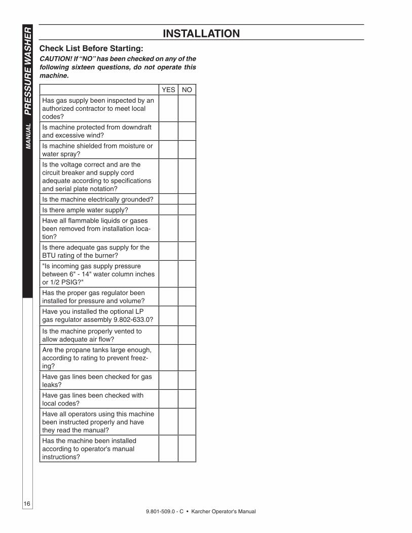
YES NO
Has gas supply been inspected by an authorized contractor to meet local codes?
Is machine protected from downdraft and excessive wind?
Is machine shielded from moisture or water spray?
Is the voltage correct and are the circuit breaker and supply cord adequate according to specifi cations and serial plate notation?
Is the machine electrically grounded?
Is there ample water supply?
Have all fl ammable liquids or gases been removed from installation loca-tion?
Is there adequate gas supply for the BTU rating of the burner?
"Is incoming gas supply pressure between 6" - 14" water column inches or 1/2 PSIG?"
Has the proper gas regulator been installed for pressure and volume?
Have you installed the optional LPgas regulator assembly 9.802-633.0?
Is the machine properly vented to allow adequate air fl ow?
Are the propane tanks large enough, according to rating to prevent freez-ing?
Have gas lines been checked for gas leaks?
Have gas lines been checked with local codes?
Have all operators using this machine been instructed properly and have they read the manual?
Has the machine been installed according to operator's manual instructions?
Check List Before Starting:CAUTION! If “NO” has been checked on any of the following sixteen questions, do not op er ate this machine.

9.801-509.0 - C • Karcher Operator's Manual17
PR
ES
SU
RE
WA
SH
ER
MA
N U
AL
98015080-698015080-5
ASSEMBLY INSTRUCTIONS
STEP 1: Attach the high pres sure hose to the spray gun. Move safety latch into locked position to prevent spray gun trigger from activating.
STEP 4: Connect the garden hose to pump wa ter inlet. In spect inlets. CAUTION: Do not run the pump without wa ter or pump damage will result.
Safety Latch
Spray Gun
High Pressure Hose
98015080-7
STEP 3: Connect garden hose to the cold water source.
Cold Water
Source
Garden Hose
98015080-10
STEP 6: Attach the Power Nozzle to end of the wand as shown in picture.
Pressure Nozzle
Wand
Guard
STEP 2: Connect the high pres sure hose to the discharge fi tting.
Pump Discharge
Fitting
STEP 5: Before installing nozzle, turn on the water supply and run machine allowing water to run from the end of the wand until clear. Turn off machine.
98015080-9
High Pressure
Hose
98015100-898015080-8
Pump Water InletGarden
Hose

9.801-509.0 - C • Karcher Operator's Manual
MA
NU
AL
PR
ES
SU
RE
WA
SH
ER
18
8
10
12
14
16
0
2
4
6
TACH/HOUR
TACH/HOUR
INSTRUCCIONES DE OPERACION
LEA EL MANUAL DE OPERACIÓN ANTES DE USARSE. LA OPERACIÓN
NADECUADA PUEDE OCASIONAR LESIONES PERSONALES O DAÑOS
A LAS PROPIEDADES.
ruptores en la posición “OFF” (A
PAGADO).
a un tomacorriente conectado a tie
rra de mo
onado por Corrie
nte de Pérdida a Tierra
ediante los procedimientos de re
GFCI debe re
iniciarse y pon
l acoplador del to
p
98015080-14
OPERATING INSTRUCTIONS
STEP 1: Have an electrician con- nect power supply into electrical box ac cord ing to information shown on the serial plate.
98015080-12
STEP 2: Turn on main gas supply and depress and turn control knob to the ‘ON’ position.
OFFON
98015080-13
STEP 3: Push pump ‘ON’ switch, or turn to pump position and pull the trig ger on the spray gun al low- ing cold water to fl ow. To activate the gas control valve for hot water, push the burner switch to the ‘ON’ po si tion and pull the trig ger on the spray gun.
Burner Switch
PumpSwitch
98015080-15
Detergent Valve
STEP 4: To apply detergent open the detergent valve coun ter clock- wise making sure that the de ter- gent pick-up tube is in the de ter gent so lu tion and not sucking air.
98016360-17
NOTE: High pressure nozzle must be attached at end of wand to obtain high pressure. To apply soap, see page 19.
Trigger
Wand
High Pressure
Nozzle
STEP 5: To Stop: Turn the burner switch off and place the detergent pick-up tube into fresh water. Open the detergent valve and trigger spray gun allowing detergent lines to be fl ushed and the burner to cool. Otherwise, coil damage will result.
After water has cooled, turn pump switch to OFF position. If the machine is going to be off for an extended period of time, put the manual valve on the gas valve into the OFF position.
Turn the water o f f. Protect from freezing.
8
10
12
14
16
0
2
4
6
TACH/HOUR
TACH/HOUR
INSTRUCCIONES DE OPERACION
LEA EL MANUAL DE OPERACIÓN ANTES DE USARSE. LA OPERACIÓN
NADECUADA PUEDE OCASIONAR LESIONES PERSONALES O DAÑOS
A LAS PROPIEDADES.
ruptores en la posición “OFF” (A
PAGADO).
a un tomacorriente conectado a tie
rra de mo
onado por Corrie
nte de Pérdida a Tierra
ediante los procedimientos de re
GFCI debe re
iniciarse y pon
l acoplador del to
p
98015080-16
Burner Switch
PumpSwitch

9.801-509.0 - C • Karcher Operator's Manual19
PR
ES
SU
RE
WA
SH
ER
MA
N U
AL
98015080-19
Detergent Valve
WARNING: Some de ter gents may be harm ful if in haled or in gest ed, caus ing severe nau- sea, fainting or poi son ing. The harm ful el e ments may cause prop er ty dam age or severe in ju ry.
STEP 1: Use detergent de signed spe cifi cal ly for pres sure wash-ers. House hold de ter gents could dam age the pump. Pre pare de-tergent so lu tion as required by the man u fac tur er. Fill a container with pres sure wash er de ter gent. Place the fi lter end of detergent suction tube into the de ter gent container.
STEP 2: Open de ter gent valve coun ter clock wise un til you ob tain de sired mix ture. De ter gent will mix with the high pres sure wa ter stream.
STEP 3: With the motor run ning, pull trig ger to op er ate ma chine. Liq uid de ter gent is drawn into the ma chine and mixed with water. Apply de ter gent to work area. Do not al low de ter gent to dry on sur face.
IMPORTANT: You must fl ush the detergent from your pressure washer after each use by plac ing the suc tion tube into a buck et of clean wa ter, then run the pres sure wash er for 1-2 minutes.
NOTE: If you remove detergent si phon tube from con tain er or allow container to empty, it will cause low pres sure by suck ing air, which will damage the pump.
THERMAL PUMP PROTECTION
If you run the engine for 3-5 min utes with out pressing the trig ger on the spray gun, cir cu lat ing water in the pump can reach high tem per a tures. When the water reach es this tem per a ture, the pump pro tec tor en gag es and cools the pump by dis charg ing the warm wa ter onto the ground. This ther mal de vice pre vents in ter nal dam age to the pump.
CLEANING TIPSPre-rinse clean ing surface with fresh water. Place de ter gent suc tion tube di rect ly into clean ing solu-tion and ap ply to surface. For best re sults, limit your work area to sec tions ap prox i mate ly 6 feet square and always ap ply de ter gent from bottom to top. Allow de ter gent to re main on sur face 1-3 min utes. Do not al low de ter gent to dry on sur face. If sur face ap pears to be dry ing, sim ply wet down sur face with fresh wa ter. If need ed, use brush to re move stub born dirt. Rinse at high pres sure from top to bottom in an even sweep ing mo tion keep ing the spray nozzle ap prox i mate ly 1 foot from clean ing sur face. Use over lap ping strokes as you clean and rinse any sur face. For best surface clean ing ac tion spray at a slight an gle.
Recommendations: • Before cleaning any surface, an inconspicuous
area should be cleaned to test spray pattern and dis tance for maximum cleaning results.
• If painted surfaces are peeling or chipping, use ex treme caution as pressure washer may re move the loose paint from the surface.
• Keep the spray nozzle a safe distance from the sur face you plan to clean. High pressure wash a small area, then check the surface for damage. If no dam age is found, continue to pressure wash ing.
CAUTION - Never use: • Bleach, chlorine products and other corrosive
chem i cals • Liquids containing solvents (i.e., paint thinner,
gas o line, oils) • Tri-sodium phosphate products • Ammonia products • Acid-based productsThese chemicals will harm the machine and will dam age the surface being cleaned.
RINSINGTurn detergent valve clockwise to close. Operate pres sure washer and allow a few sec onds for the de ter gent to clear.
WARNING
98015080-20
98015080-18
APPLYING DETERGENT & GENERAL OPERATING TECHNIQUES

9.801-509.0 - C • Karcher Operator's Manual
MA
NU
AL
PR
ES
SU
RE
WA
SH
ER
20
RUCCIONES D
ERACIÓN ANTE
ONAR LES
OPIE98015100-21
CAUTION: Fail ure to follow the above di rec tions will result in dam age to your pres sure washer.
After Extended StorageCAUTION: Prior to restarting, thaw out any pos si ble ice from pressure washer hos es, spray gun or wand.
SHUTTING DOWN AND CLEANUP
STORAGE
CAUTION: Al ways store your pres sure washer in a lo ca tion where the temper-ature will not fall be low 32°F (0°C). The pump in this machine is sus cep ti ble to
permanent dam age if fro zen. FREEZE DAM AGE IS NOT COV ERED BY WAR RAN TY.
1. Stop the pressure washer, squeeze spray gun trig ger to release pressure.
2. Detach water supply hose and high pressure hose.
3. Turn on the machine for a few seconds, until re main ing water exits. Turn pump off immediately.
4. Do not allow high pres sure hose to become kinked.
5. Store the machine and accessories in a room which does not reach freezing tem per a tures.
STEP 1: Turn the burner switch to the ‘OFF’ position.
Burn er Switch
STEP 2: Place the detergent tube in fresh water and open the de ter gent valve and spray gun, allowing the detergent lines to be fl ushed and the burner to cool. Otherwise coil dam age may occur.
RUCCIONES D
ERACIÓN ANTE
ONAR LES
OPIE98015100-23
Pump Switch
STEP 3: After water has cooled, push or turn pump switch to ‘OFF’ position. If the machine will be turned off for an extended period of time, put the gas cock on the gas valve in the ‘OFF’ position.
STEP 4: Turn off water.
98015100-24
98015080-22
Test
res
and
out-
on.
ght
and
INSTRUCCIONES DE OPERACIO
LEA EL MANUAL DE OPERACIÓN ANTES DE USARSE. LA OPERACI
INADECUADA PUEDE OCASIONAR LESIONES PERSONALES O DAÑOS
A LAS PROPIEDADES.
NE.
Y OR
1. Coloque todos los interruptores en la posición “O
FF” (APAGADO).
2. Conecte la fuente de energía a un tomacorriente conectado a tie
rra de modo ad-
ecuado. Pruebe el In
terruptor A
ccionado por Corrie
nte de Pérdida a Tierra (G
FCI
por sus siglas en In
glés) (si h
ubiera) mediante lo
s procedimientos de reinicio y
prueba incorporados en dicho dispositivo. E
l GFCI d
ebe reiniciarse y ponerse a
prueba cada vez que se use.
3. Asegure la manguera de alta presión, p
istola y varilla
al acoplador del to
macor-
riente.
4. Conecte la manguera de suministro de agua y abra la lla
ve.
5. Sujete
la va
rilla. C
oloque el interru
ptor de la
bomba en la posición
“ON” (ENCENDIDO).
6. Coloque la perilla de contro
l de la válvula de gas en la posición “ON” (E
NCENDI-
DO). El piloto se encenderá automáticamente cuando el quemador se encienda.
7. A de calentar e
l agua, coloque el interru
ptor del quemador e
n la posición “ON”
(ENCENDIDO) y ajuste el term
ostato a la temperatura deseada.
8. Encienda el detergente y proceda con la limpieza.
9. Después de limpiar:
A. Apague el detergente y enjuague.
B. Ponga el in
terruptor d
el quemador en la posición “O
FF” (APAGADO).
C. Deje que la máquina descargue agua por 2
ó 3 minutos para que se
enfríe el serpentín.
D. Ponga el in
terruptor d
e la bomba en la posición “OFF” (A
PAGADO).
E. Presione la pistola para aliviar la
presión del sistema.
F.
Cierre el suministro
de agua.
1. Met
2. Connecte
mise à la terre
à l’aide des procédu
disjoncteur. Le disjoncteu
sation.
3. Fixez le tuyau à haute pression, le
pi
de sortie.
4. Connectez le tuyau à eau et faites couler l’e
au.
5. Tenez le tube rig
ide fermement. M
ettez l’interru
pteur
position “O
N”.
6. Tournez le bouton du ro
binet de gaz en positio
n “ON”.
La veil
s’allume automatiquement lorsque l’in
terrupteur d
u brûleur est mis sur
“ON”.
7. Pour chauffer l’eau, m
ettez l’interru
pteur du brûleur sur “O
N” et ré
glez
le thermostat à
la température voulue.
8. Activez le détergent et commencez le nettoyage.
9. Après le nettoyage :
A. Coupez le détergent e
t rincez.
B. Mettez l’in
terrupteur d
u brûleur sur “OFF”.
C. Laissez la machine évacuer l’e
au pendant 2 à 3 minutes, le
temps que la bobine refro
idisse.
D. Mettez l’in
terrupteur d
e la pompe sur “OFF”.
E. Actionnez le pistolet pour ré
duire la pression du système.
F.
Coupez l’eau.
WARNING
PRECAUCION / AVERTISSEMENT
SK
AL
E
NE
BY
ORS.
LEA EL MANUAL OPERACION ANTES
DE USARSE. ESTE EQUIPO DEBE SER
USADO SOLAMENTE POR OPERA-
DORES CALIFICADOS.
LIRE LE MANUEL DE L’OPERATEUR
AVANT UTILISATION. CET APPAREIL
DOIT ETRE UTILISE PAR DES OPERA-
TEURS QUALIFIES.
NG
PROTEJASE LOS OJOS CU-
ANDO se opere este equipo.
DES LUNETTES DE SECURITE
DOIVENT ETRE PORTEES
lorsque vous operez cet a
ppareil.
e
RIESGO DE ASFIXIA. Use el
producto en un area de venti-
lación adecuada.
RISQUE D’ASPHYXIE. Utilis
er
dans un endroit bien aéré.
RISK OF
ELECTROCUTION. Connect o
nly to
properly grounded outlet. Keep all c
on-
nections dry and off the ground. K
eep
spray away from electric
al wirin
g and
components. Disconnect fr
om electrical
supply before servicing.
RIESGO DE ELECTROCUCIÓN — Co-
necte el enchufe en un contacto adecuado.
Mantenga todas las connecciones secas
y arriba del suelo. N
o rocie componentes
de
vec
t.
us-
er
es.
une
RISK OF INJECTION OR SE-
VERE INJURY TO PERSONS.
Keep clear of n
ozzle.
HOT DISCHARGE FLUID —Do
not touch or d
irect d
ischarge
stream at p
ersons.
RIESGO DE PENETRACIÓN O
LESIONES SEVERAS A PERSO-
NAS. Manténgase fu
era del alcance
de boquilla.
DESCARGA DE AGUA CALIENTE
A ALTA PRESION — No to
que
ni dirija el
del agua a otras
personas.
RISQUE DE BLESSURES. Se te
nir
loin des buses.
EAU CHAUDE SOUS PRESSION A
LA SORTIE — Ne pas dirig
er le jet
d’eau vers des personnes.
SPRAY GUN KICKS BACK
— Hold with both hands.
LA PISTOLA SE MUEVE CON
LA PRESIÓN — Sostenga con las
dos manos.
LA POIGNEE PISTOLET RE-
POUSSE — Tenir à
deux mains.RISK OF IN
JURY—HOT
SURFACES CAN CAUSE
BURNS — Use only
designed gripping areas of
spray gun and wand.
SUPERFICIES CALIENTES
— Use solamente las áreas
aisladas del gatillo y la lanza.
SURFACES CHAUDES —
Toucher seulement le
s parties
isolées des poignée pistolets
et lances.
RIESGO DE EXPLOSION — Use
el producto en áreas donde el fuego
o llama sean perm
itidos. N
o rocie
liquidos
RISQUE D’EXPLOSION — Utilis
er
aux endroits où une
nue est
permise. N
e pas vaporiser d
e liquides
RISK OF
EXPLOSION. Operate only
where open
or torch is perm
itted.
Do not spray
liquids.
RISQUE DE FEU OU D’EXPLOSION
RIESGO DE INCENDIO O EXPLOSIÓN
OSION
combustible
nce area for
se some gas
If you smell
structions. I
f
department.
control knob.
l a
g repair m
ay
nob to O
FF
been under
n to in
spect
El equipo debe ser in
stalado sobre un piso resistente
al incendio, con un espacio lib
re de 18” minimo.
Antes de encender, o
lfatee alrededor d
el aparato para
detectar gas. E
sté seguro de revisar c
erca del piso,
porque ciertos gases son m
ás pesados que el aire. S
i
olfatea gas, avise in
mediatamente a su proveedor de
gas. Al no localizar el proveedor, ll
ame a los bomberos.
No use herra
mientas para mover e
l contro
l del g
as.
Si la m
anija no se puede operar con la m
ano, llame a
un técnico capacitado. F
orzar o in
tentar reparar e
ste
control puede re
sultar en un incendio o explosión.
En el caso de apagarse el p
iloto, apague y espere 5
minutos antes de encender.
No utilic
e este equipo en el caso que hubiera estado
sumergido en agua parcial o to
talmente un compo-
nente. Consulte con un té
cnico de servicio.
Ne pas in
staller ce m
achine aux endroits où il y a des
combustibles (même les plancher) d
edans un demi-mètre
.
Avant l’
allumage,
autour de l’a
ppareil pour d
es
senteurs de gaz.
les odeurs près du plancher car
certains gaz sont plus lourds que l’a
ir et s’accumulent sur
le plancher. Si vo
us détectez une odeur de gaz, a
ppelez
immédiatement votre
fournisseur d
e gaz. Si c
elui-ci ne
peut être
joint, appeler le
département d
es incendies.
Ne pas utilis
er d’outils pour pousser ou tourner la
soupape
de contrôle du gaz. S
i la soupape ne peut être
enfoncée ou
tournée à la main, appeler un technicien
Forcer ou
essayer de ré
parer peut causer u
n feu ou une explosion.
Si le
pilote s’éteint, tourner la
soupape de contrôle en
position OFF. A
ttendre 5 m
inutes avant de ré
allumer.
Ne pas utilis
er cet équipement si une partie a été im
mergée
dans l’eau. A
ppeler un te
chnicien pour inspecter c
elui-ci.
8.900-990.0
Detergent Tube
Fresh Water

9.801-509.0 - C • Karcher Operator's Manual21
PR
ES
SU
RE
WA
SH
ER
Trou
blesh
oo
ting
Gu
ide
TROUBLESHOOTING
PROBLEM POSSIBLE CAUSE SOLUTION
WATER TEMPERATURE TOO HOT
Incoming water to machine warm or hot Lower incoming water temperature.
Gas pressure too high See specifi cations for proper gas pressure.
Detergent line sucking air Tighten all clamps. Check detergent lines for holes.
Defective high limit switch Replace.
Incorrect burner nozzle size See serial plate.
Insuffi cient water supplied Check water GPM to machine.
Restricted water fl ow Check nozzle for obstruction, proper size.
PRESENCE OF WATER IN OIL
Oil seal worn Check and replace if necessary.
High humidity in air Check and change oil twice as often.
WATER DRIPPING FROM UNDER PUMP
Piston packing worn Check and replace if necessary.
O-Ring plunger retainer worn Check and replace if necessary.
DETERGENT NOT DRAWING
Air leak Tighten all clamps. Check detergent lines for holes.
Detergent metering valve packing not tight or packing worn
Tighten nut. Replace valve or packing.
Filter screen on detergent suction hose plugged
Clean or replace.
Dried up detergent plugging metering valve Disassemble and clean thoroughly.
High viscosity of detergent Dilute detergent to specifi cations.
Restriction behind fl oat tank screen removed
Install restriction.
Hole in detergent line(s) Repair hole.
Strainer basket plugged Remove and clean.
Connections on selector valve loose Put tefl on tape on all pipe connections.
Detergent solenoid not opening (where applicable)
Check fl ow switch, replace detergent solenoid.
PUMP RUNNING NORMALLY BUT PRESSURE LOW ON INSTALLATION
Pump sucking air Check water supply and possibility of air.
Valves sticking Check and clean or replace if necessary.
Unloader valve seat faulty Check and replace if necessary.
Nozzle incorrectly sized Check and replace if necessary (See serial plate for proper size).
Worn piston packing Check and replace if necessary.
FLUCTUATING PRESSURE
Valves worn Check and replace if necessary.
Blockage in valve Check and replace if necessary.
Pump sucking air Check water supply and air seepage at joints in suction line.
Worn piston packing Check and replace if necessary.
PUMP NOISY
Air in suction line Check water supply and connections on suction line.
Broken or weak inlet or discharge valve springs
Check and replace if necessary.
Excessive matter in valves Check and clean if necessary.
Worn bearings Check and replace if necessary.

9.801-509.0 - C • Karcher Operator's Manual
PR
ES
SU
RE
WA
SH
ER
T
rou
ble
sho
oti
ng
Gu
ide
22
TROUBLESHOOTING
PROBLEM POSSIBLE CAUSE SOLUTION
OIL
DRIPPING
Oil seal worn Check and replace if necessary.
LOW OPERATING PRESSURE
Faulty pressure gauge Install new gauge.
Insuffi ent water supply Use larger garden hose. Clean fi lter washer at water inlet.
Old, worn or incorrect spray nozzle Match nozzle number to machine and /or replace new nozzle.
Belt Slippage Tighten or replace. Use correct belt.
Plumbing or hose leak Check plumbing system for leaks. Retape leaks with tefl on tape.
Faulty or misadjusted unloader valve (where applicable)
Adjust unloader for proper pressure. Install repair kit when needed.
Worn packing in pump Install new packing kit.
Fouled or dirty inlet or discharge valves in pump
Clean inlet and discharge valve.
Worn inlet or discharge valves Replace with valve kit.
Obstruction in spray nozzle Remove obstruction.
Leaking pressure control valve (where applicable)
Rebuild or replace as needed.
Detergent metering valve left open sucking air or faulty metering valve
Close and /or replace metering valve.
Slow motor RPM Check incoming voltage.
LOW WATER TEMPERATURE
Improper size of gas lines See sizing gas lines.
Low gas pressure Increase gas pressure to machine.
Improper pressure regulator Specify BTU, building gas pressure 11 w.c.i. to machine for correct sizing of regulator.
Low gas pressure Increase gas pressure
Soot buildup on coils not allowing heat transfer
Clean coils.
Improper burner nozzle See serial plate.

9.801-509.0 - C • Karcher Operator's Manual23
PR
ES
SU
RE
WA
SH
ER
Trou
blesh
oo
ting
Gu
ide
TROUBLESHOOTING
PROBLEM POSSIBLE CAUSE SOLUTION
FLOW & BURNER SWITCH ON; NO SPARK, NO PILOT GAS
A. No main power
B. Faulty transformer
C. Faulty burner & fl ow switch
D. Faulty ignition control unit
With power switch on, open trigger on spray gun and set your test meter to the 24 volt scale. Probe terminals 24V and 24V(GND). If you do not read 24 volts, the problem is not the ignition system. Perform normal system checks of main power, transformer, thermostat and the limit control. If you do read 24 volts at TH and GND, the problem is in the ignition system. Check for loose or defective wiring. If wiring is good, replace the ignition control unit.
HAVE SPARK, NO PILOT GAS FLOW
Main gas supply turned off Set test meter to 24 volt scale.
1. Be sure main gas valve (gas cock or selector arm) is turned on.
2. With gas on and system sparking, probe terminals PV and 24V(GND). If pilot gas does not fl ow with 24 volts at these terminals, replace gas valve.
3. Probe terminals PV and MV/PV. If 24 volts not present, replace ignition control box.
HAVE PILOT GAS, NO SPARK
A. Defective ignitor/sensor and or its wiring
Set test meter to ohm scale.
1. Disconnect the wire from the IGN terminal on the ignition control unit.
B. Faulty ignition control unit 2. Touch one meter probe to the tip of the ignitor/sensor rod in the pilot. Touch the other probe to the quick connect at the other end of ignitor/sensor wire.
3. If you have continuity from the tip of the ignitor/sensor rod to the connector and no spark, replace the ignition control unit.
4. If you do not have continuity through wire and the ignitor/sensor, check for a loose wire connection in the wire. Repair as needed.
5. Check to see if spark shorts to burner ring through a cut in the ignitor wire.

9.801-509.0 - C • Karcher Operator's Manual
PR
ES
SU
RE
WA
SH
ER
T
rou
ble
sho
oti
ng
Gu
ide
24
TROUBLESHOOTING
PROBLEM POSSIBLE CAUSE SOLUTION
HAVE PILOT FLAME, MAIN BURNER WILL NOT TURN ON
Faulty main valve coil in thegas valve
Set test meter to 24 volt scale.
Faulty ignitor/sensor and/or its wiring
With pilot fl ame on ignitor/sensor, probe terminals MV and MV/PV on the ignition control unit. If you read 24 volts here, but not at the gas valve, there is a loose wiring connection. Repair or replace as needed.
Ground wire not attached to machine chassis
If you do read 24 volts at MV and MV/PV and the pilot fl ame is impinging on the ignitor/sensor rod, the problems may be:
Faulty ignition control unit a. Faulty ignitor/sensor and/or its wiring.
b. Faulty ignition control unit.
Set test meter to the ohm scale. Turn burner switch off.
Check continuity through the green ground wire and its connections.
Reconnect the ignitor/sensor wire and the ground wire.
Turn burner switch on. With the pilot burning and the fl ame on the ignitor/sensor rod, the main burner should turn on. If it does not, replace the ignition control unit.
SHORT-CYCLING OF MAIN BURNER. MAIN BURNER TURNS OFF BEFORE THE BURNER SWITCH OR FLOW SWITCH IS TURNED OFF
Draft condition pulls fl ame from ignitor/sensor rod.
Check the thermostat by bypassing at terminals P1 & 1.
Set thermostat high. With main burner on, observe the pilot fl ame impingement on the ignitor/sensor.
Faulty thermostat or water temperature is too high
If pilot fl ame is small and draft condition pulls fl ame from ignitor sensor rod, the burner will turn off and then on again. a. Adjust pilot fl ame higher or clean pilot oriface. b. Bend ignitor/sensor rod closer to pilot fl ame.
If fl ame impingement on the ignitor/sensor is stable and the system short-cycles, check the limit switch.
Set test meter to 110 volt scale; a. When the system cycles off, probe the switch terminals of the limit switch. b. If you read 24V accross the switch terminals the limit switch is open. Replace the limit switch.
A pilot fl ame set too high will also cause burner to short cycle. Pilot fl ame lifts over ignitor/sensor.

9.801-509.0 - C • Karcher Operator's Manual25
PR
ES
SU
RE
WA
SH
ER
MA
N U
AL
MAINTENANCE AND SERVICE
Spray Nozzles:Each machine is equipped with one or more spray noz zles, de pend ing on the model. Different spray noz zles are cal i brat ed for each machine, depending on the fl ow and pres sure of that particular model. Spray nozzles vary in bore size and angle of spray. Popular spray angles are 0°, 15°, 25°, 40°. When ordering, please specify size and angle of nozzle. Nozzle size for each machine is located on the serial plate.
Unloader Valves:Unloader valves relieve pressure in the line when a spray gun is closed. Unloader valves are pre set and test ed at the factory before shipping. Oc ca sion al ad- just ment of the unloader may be necessary to main tain cor rect pres sure. For valve adjustment contact your nearest dealer or call technical support. Tampering with the factory setting may cause personal injury and/or property damage, and will void the manufacturer's warranty.
Winterizing Procedure:Damage due to freezing is not covered by warranty. Adhere to the following cold weather procedures when- ev er the wash er must be stored or operated out doors under freez ing conditions.
It is necessary to protect your machine against freez- ing when temperatures drop below 32° F. Si phon ing a small amount of antifreeze into the sys tem is rec om- mend ed. This is done by pouring a 50-50 mix of an ti- freeze and wa ter into the fl oat tank and then si phon ing 100% an ti freeze through the detergent line with the pump on. If com pressed air is avail able, an air fi t ting can be screwed into the fl oat tank strain er fi t ting, and by in ject ing com pressed air, all water will be blown out of the system. The use of a draft diverter will prevent the wind chill fac tor from freez ing the coil.
Low Pressure Diagnosis:(Machines with spray gun)
Refer to Troubleshooting Chart for low pressure. If the trou ble is found to be either the unloader or the pump, your next step is to determine which is the problem. This can be done by eliminating the unloader from the sys tem and at tach ing the 50' discharge hose di rect ly to the pump. If high pres sure is developed in this man- ner, the pump is good and the unloader needs to be repaired or replaced. If low pressure is still present, then the pump needs re pair ing.
CAUTION: When using this procedure to test com po nents keep the spray gun open at all times.
High Limit Hot Wa ter Thermostat:For safety, each machine is equipped with a high limit con trol switch. In the event the temperature of the wa ter
should exceed its operating temperature, the high limit control will turn the burner off until the water cools.
Pumps:Use only SAE 20/40 weight non-detergent oil. Change oil af ter fi rst 50 hours of use. Thereafter, change oil ev ery three months or at 500 hour intervals. Oil level should be checked through use of the dipstick found on the top of the pump or by the red dot visible through the oil gauge window. Oil should be maintained at that level.
HEATING COILSTo Check Water Heater Coil for Leaks:With the main burners “OFF” start the pumping unit and allow it to run for a few minutes. Check into the burner com part ment with a drop light or fl ashlight. If no leaks are vis i ble, then water dripping from coils is con den sa tion from the fl ue gases when the burners are on.
Condensation from Heating Coil:When cold water is being pumped into the water heat er coils, and the burners are on, condensation will form on the coils and drip down into the burner com part ment, giv ing the ap pear ance of a leaking coil, par tic u lar ly on cold humid days.
Deliming Coils:In alkaline water areas, lime deposits can ac cu mu late rap id ly inside the coil pipes. This growth is in creased by the extreme heat build up in the coil. The best pre ven tion for liming conditions is to use high quality clean ing de ter gents. In areas where alkaline water is an extreme prob lem, pe ri od ic use of Mongoose Coil Con di tion er (part # 8.914-296.0) will re move lime and other de pos its be fore coil be comes plugged. (See the fol low ing in struc tions for use of Coil Con di tion er.)
Periodic fl ushing of coils is recommended.
1. Fill a container with 2 gallons of water, then add 1 lb. of deliming powder. Mix thoroughly.
2. Remove nozzle from spray gun assembly and put spray gun into con tain er. Secure the trigger on the spray gun into the open po si tion.
3. Attach a short section (3-5 ft.) of garden hose to ma chine to siphon solution from an elevated con- tain er, or add mixture to the fl oat tank. Turn pump switch on al low ing so lu tion to be pumped through coils and back into the con tain er. So lu tion should be allowed to cir cu late 2-4 hours.
4. After circulating solution, fl ush entire system with fresh water. Reinstall wand assembly to spray gun.
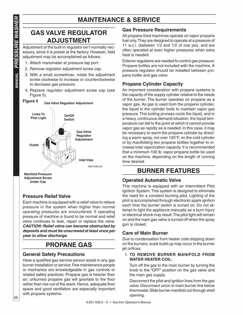
9.801-509.0 - C • Karcher Operator's Manual
MA
NU
AL
PR
ES
SU
RE
WA
SH
ER
26
MAINTENANCE & SERVICE
Gas Valve Regulator Adjustment
GAS VALVE REGULATOR ADJUSTMENT
Adjustment of the built-in regulator isn’t normally nec-essary, since it is preset at the factory. However, fi eld adjustment may be accomplished as follows:
1. Attach manometer at pressure tap port.
2. Remove regulator adjustment screw cap.
3. With a small screwdriver, rotate the adjustment screw clockwise to increase or counterclockwise to decrease gas pressure.
4. Replace regulator adjustment screw cap (see Figure 5).
Figure 5
Pressure Relief ValveEach machine is equipped with a relief valve to relieve pressure in the system when higher than normal operating pressures are encountered. If operating pressure of machine is found to be normal and relief valve continues to leak, repair or replace the valve. CAUTION: Relief valve can become obstructed by deposits and must be unscrewed at least once per year to allow discharge.
PROPANE GASGeneral Safety PrecautionsHave a qualifi ed gas service person assist in any gas burner installation or service. Few maintenance people or mechanics are knowledgeable in gas controls or related safety practices. Propane gas is heavier than air; unburned propane gas will gravitate to the fl oor rather than rise out of the stack. Hence, adequate fl oor space and good ventilation are especially important with propane systems.
Gas Pressure RequirementsAll propane fi red machines operate on vapor propane fuel only. They are designed to operate at a pressure of 11 w.c.i. (between 1/3 and 1/2 of one psi), and are often operated at even higher pressures when extra heat is needed.
Exterior regulators are needed to control gas pressure. Propane bottles are not included with the machine. A pressure regulator should be installed between pro-pane bottle and gas valve.
Propane Cylinder CapacityAn important consideration with propane systems is the capacity of the supply cylinder relative to the needs of the burner. The burner operates on propane as a vapor gas. As gas is used from the propane cylinder, the liquid in the cylinder boils to maintain vapor gas pressure. This boiling process cools the liquid, and in a heavy, continuous-demand situation, the liquid tem-perature can fall to the point at which it cannot provide vapor gas as rapidly as is needed. In this case, it may be necessary to warm the propane cylinder by direct-ing a warm spray, not over 120°F, on the cold cylinder or by manifolding two propane bottles together to in-crease total vaporization capacity. It is recommended that a minimum 100 lb. vapor propane bottle be used on the machine, depending on the length of running time desired.
BURNER FEATURESOperated Automatic ValveThis machine is equipped with an Intermittent Pilot Ignition System. This system is designed to eliminate the need for a constant burning pilot. Lighting of the pilot is accomplished through electronic spark ignition each time the burner switch is turned on. Do not at-tempt to light the appliance manually as a burn injury or electrical shock may result. The pilot light will remain on and the main gas valve is turned off when the spray gun is closed.
Care of Main BurnerDue to condensation from heater coils dripping down on the burners, scale build-up may occur in the burner jet orifi ces.
1. TO REMOVE BURNER MANIFOLD FROM WATER HEATER COIL:
Turn off the gas to the main burner by turning the knob to the “OFF” position on the gas valve and the main gas supply.
Disconnect the pilot and ignition lines from the gas valve. Disconnect union in main burner line below thermostat. Slide burner manifold out through shell opening.
On/Off Switch
Inlet View
Outlet
Manifold Pressure Adjustment Screw
Under Cap
Gas Valve Regulator
Adjustment
Lines To Pilot Light
98015080-26

9.801-509.0 - C • Karcher Operator's Manual27
PR
ES
SU
RE
WA
SH
ER
MA
N U
AL
MAINTENANCE & SERVICE
2. TO CLEAN BURNER JETS:
Select proper size drill for type gas involved. Use pin vise to hold drill and ream out each jet orifi ce. CAUTION: Do not ream out orifices to a larger size.
If the water heater will be exposed to freezing weather, an anti-freeze solution should be circulated through the coil by whatever means are available for the particular system the water heater is used on.
To Adjust Pressure RegulatorAdjustment of the pressure regulator is not normally necessary since it is preset at the factory. However, fi eld adjustment may be accomplished as follows:
1. Manometer attachment may be accomplished at the pressure tap plug.
2. Remove regulator adjustment screw cap (see Figure 5, page 23).
3. With small screwdriver, rotate adjustment screw clockwise to increase, or counterclockwise to decrease pressure.
4. Replace regulator adjustment screw cap.

9.801-509.0 - C • Karcher Operator's Manual
MA
NU
AL
PR
ES
SU
RE
WA
SH
ER
28
MAINTENANCE AND SERVICE
BASIC FACTS
Based on 60° Propane Butane
1 Cu. Ft. NG Approx 1000 BTU
Formula C3H8 C4H10
Vaporization Point (°F) -43.7 31.1
Specifi c Gravity (Vapor) 1.522 2.006
Specifi c Gravity (Liquid) 0.508 0.584
Lbs. per Gal. (Liquid) 4.23 4.87
BTU per Cu. Ft. (Vapor) 2.563 3.39
BTU per Gal. (Liquid) 91.547 102.032
BTU per Lb. (Liquid) 21.591 21.221
Cu. Ft. per Lb. (Liquid) 8.607 6.53
Cu. Ft. per Gal. (Liquid) 36.45 31.8
Octane Number 125 91
Molecular Weight 44.09 58.12
To Calculate Running Cost: 1,000 BTU = 1 Cu. Ft.
100 Cu. Ft. = 1 Therm
1 Therm = 1 Hour
Cost of Gas per Therm = Cost to Run
Example Using Natural Gas at 50¢ Therm:
400,000 BTU Machine
400 Cu. Ft. (400,000 / 1,000)
4 x 50¢ = $2.00 / Hour to Run ((400 / 100) x cost of gas)

9.801-509.0 - C • Karcher Operator's Manual29
PR
ES
SU
RE
WA
SH
ER
MA
N U
AL
OIL CHANGE RECORD
PRESSURE EQUIVALENTSSimply stated, pressure is the force exerted by a gas or liquid attempting to escape from a container. It is useful to know how strong this “attempt to escape” is. Pressure can be mea sured with a manometer or with a pressure gauge. At the low er levels, it is expressed in water column inches i.e. 11 w.c.i. Higher pressures are ex pressed in terms of the force exerted against a square inch of area, for example, 125 lbs. per square inch (125 psi).
MAINTENANCE AND SERVICE
1" Water Column = 50 oz./sq. in. 11" Water Column = 6.35 oz./sq. in.
11" Water Column = 4 lb./sq. in. 1 lb./sq. in. = 27.71" Water Column
1 lb./sq. in. = 14.73 lbs./sq.in 1" Mercury = .39 lb./sq. in
1 Std. Atmosphere = 14.73 lbs./sq. in.
Date Oil Changed Month/Day/Year
Estimated Operating Hours Since Last Oil Change

9.801-509.0 - C • Karcher Operator's Manual
MA
NU
AL
PR
ES
SU
RE
WA
SH
ER
30
PREVENTATIVE MAINTENANCE
This pressure washer was produced with the best avail able ma te ri als and quality craftsmanship. However, you as the own er have certain re spon si bil i ties for the correct care of the equip ment. At ten tion to reg u lar pre ven ta tive main te nance pro ce dures will as sist in preserving the performance of your equipment. Contact your dealer for main te nance. Regular preventative maintenance will add many hours to the life of your pres sure washer. Perform maintenance more often under severe conditions.
MAINTENANCE SCHEDULE
Replace Fuel Lines Annually
Pump OilInspect Daily inspect the oil level
Change After fi rst 50 hours, then every 500 hours or annually
Clean Burner Filter Annually
Remove Burner Soot From Heating Coil Annually
Check Belt Tension Monthly
Descale Coil Annually - (more often if required)
Replace High Pressure Nozzle Every 6 months
Replace Quick Connects Annually
Clean Water and Chemical Screen/Filter Weekly
Clean Float/Supply Tank Every 6 months
Replace HP Hose If there is any sign of wear
Grease Motor Every 10,000 hours
Check Burner Pilot Jets Annually
Pressure Relief Valve Annually


HDS • 9.801-509.0 • Printed in U.S.A.