Embed Size (px)
Citation preview

TECHNICAL MANUAL
Henny PennyHumidified Holding Cabinets
Model HHC-980Model HHC-983


Model HHC-980/983
FM06-002Revised 07-30-07
LIMITED WARRANTY FOR HENNY PENNY EQUIPMENT
Subject to the following conditions, Henny Penny Corporation makes the following limited warranties to the originalpurchaser only for Henny Penny appliances and replacement parts:
NEW EQUIPMENT: Any part of a new appliance, except baskets, lamps, and fuses, which proves to be defective inmaterial or workmanship within two (2) years from date of original installation, will be repaired or replaced withoutcharge F.O.B. factory, Eaton, Ohio, or F.O.B. authorized distributor. Baskets will be repaired or replaced for ninety (90)days from date of original installation. Lamps and fuses are not covered under this Limited Warranty. To validate thiswarranty, the registration card for the appliance must be mailed to Henny Penny within ten (10) days after installation.
FILTER SYSTEM: Failure of any parts within a fryer filter system caused by the use of the non-OEM filters orother unapproved filters is not covered under this Limited Warranty.
REPLACEMENT PARTS: Any appliance replacement part, except lamps and fuses, which proves to be defective inmaterial or workmanship within ninety (90) days from date of original installation will be repaired or replaced withoutcharge F.O.B. factory, Eaton, Ohio, or F.O.B. authorized distributor.
The warranty for new equipment covers the repair or replacement of the defective part and includes labor charges andmaximum mileage charges of 200 miles round trip for a period of one (1) year from the date of original installation.
The warranty for replacement parts covers only the repair or replacement of the defective part and does not include anylabor charges for the removal and installation of any parts, travel, or other expenses incidental to the repair or replacement ofa part.
EXTENDED FRYPOT WARRANTY: Henny Penny will replace any frypot that fails due to manufacturing or workmanshipissues for a period of up to seven (7) years from date of manufacture. This warranty shall not cover any frypot that fails due toany misuse or abuse, such as heating of the frypot without shortening.
0 TO 3 YEARS: During this time, any frypot that fails due to manufacturing or workmanship issues willbe replaced at no charge for parts, labor, or freight. Henny Penny will either install a new frypot at no cost orprovide a new or reconditioned replacement fryer at no cost.
3 TO 7 YEARS: During this time, any frypot that fails due to manufacturing or workmanship issues willbe replaced at no charge for the frypot only. Any freight charges and labor costs to install the new frypot aswell as the cost of any other parts replaced, such as insulation, thermal sensors, high limits, fittings, andhardware, will be the responsibility of the owner.
Any claim must be presented to either Henny Penny or the distributor from whom the appliance was purchased. Noallowance will be granted for repairs made by anyone else without Henny Penny’s written consent. If damage occurs duringshipping, notify the sender at once so that a claim may be filed.
THE ABOVE LIMITED WARRANTY SETS FORTH THE SOLE REMEDY AGAINST HENNY PENNY FOR ANY BREACHOF WARRANTY OR OTHER TERM. BUYER AGREES THAT NO OTHER REMEDY (INCLUDING CLAIMS FOR ANY INCI-DENTAL OR CONSEQUENTIAL DAMAGES) SHALL BE AVAILABLE.
The above limited warranty does not apply (a) to damage resulting from accident, alteration, misuse, or abuse; (b) if theequipment’s serial number is removed or defaced; or (c) for lamps and fuses. THE ABOVE LIMITED WARRANTY IS EXPRESSLYIN LIEU OF ALL OTHER WARRANTIES, EXPRESS OR IMPLIED, INCLUDING MERCHANTABILITY AND FITNESS, ANDALL OTHER WARRANTIES ARE EXCLUDED. HENNY PENNY NEITHER ASSUMES NOR AUTHORIZES ANY PERSON TOASSUME FOR IT ANY OTHER OBLIGATION OR LIABILITY.
Revised 01/01/07

Model HHC-980/983
TABLE OF CONTENTS
Section Page
Section 1. TROUBLESHOOTING1-1. Introduction ................................................................................................................. 1-11-1. Safety .......................................................................................................................... 1-11-3. Troubleshooting .......................................................................................................... 1-11-4. Error Codes and Warnings .......................................................................................... 1-51-5. Info Mode .................................................................................................................... 1-8
Section 2. LEVEL 2 PROGRAMMING2-1. Introduction ................................................................................................................. 2-12-2. Tech Mode................................................................................................................... 2-12-3. Stats Mode................................................................................................................... 2-52-4. Data Logging and Manufacturing Mode ..................................................................... 2-8
Section 3. MAINTENANCE3-1. Introduction ................................................................................................................. 3-13-2. Maintenance Hints ...................................................................................................... 3-13-3. Humidity Sensor Calibration and Replacement .......................................................... 3-13-4. Fuse and Fuse Holder Assembly ................................................................................. 3-43-5. Power Switch Replacement ........................................................................................ 3-53-6. Air Temperature Probe Replacement .......................................................................... 3-63-7. Transformer Replacement ........................................................................................... 3-83-8. Relay Replacement ..................................................................................................... 3-93-9. Module Top Removal .................................................................................................. 3-10
3-10. Cooling Fan Replacement ........................................................................................... 3-113-11. High Limit - Air Heater Replacement ......................................................................... 3-113-12. Blower Motor Replacement ........................................................................................ 3-123-13. Air Heater Replacement .............................................................................................. 3-133-14. Speaker Replacement .................................................................................................. 3-133-15. Complete Panel or PC Board Replacement ................................................................ 3-143-16. Float Switch Replacement .......................................................................................... 3-153-17. High Limit - Water Heater Replacement ..................................................................... 3-163-18. Water Heater Replacement .......................................................................................... 3-173-19. Drain Valve Replacement ............................................................................................ 3-183-20. Cleaning Water Strainer .............................................................................................. 3-193-21. Water Valve (Solenoid) Replacement ......................................................................... 3-193-22. Door Gasket Replacement .......................................................................................... 3-21
Wiring Diagrams ......................................................................................................... 3-22
Section 4. PARTS INFORMATION4-1. Introduction ................................................................................................................. 4-14-2. Genuine Parts .............................................................................................................. 4-14-3. When Ordering Parts ................................................................................................... 4-14-4. Prices ........................................................................................................................... 4-14-5. Delivery ....................................................................................................................... 4-14-6. Warranty ...................................................................................................................... 4-14-7. Recommended Spare Parts for Distributors ............................................................... 4-1
Parts List ..................................................................................................................... 4-2
i 206

Model HHC-980/983
This section provides troubleshooting information in the formof an easy to read table.
If a problem occurs during the first operation of a cabinet,recheck the installation per the Installation Section of theOperator’s Manual
Before troubleshooting, always recheck the operation proce-dures in the Operator’s manual.
203 1-1
SECTION 1. TROUBLESHOOTING
1-1. INTRODUCTION
1-3. TROUBLESHOOTING To isolate a malfunction, proceed as follows:1. Clearly define the problem or symptom and when it occurs.2. Locate the problem in the troubleshooting table.3. Review all possible causes. Then, one at a time work through
the list of corrections until problem is solved.
If maintenance procedures are not followed correctly,injuries and/or property damage could result.
1-2. SAFETY Where information is of particular importance or is safetyrelated, the words NOTICE, CAUTION, or WARNING areused. Their usage is described below.
SAFETY ALERT SYMBOL is used with DANGER,WARNING, or CAUTION which indicates a personalinjury type hazard.
NOTICE is used to highlight especially importantinformation.
CAUTION used without the safety alert symbol indicatesa potentially hazardous situation which, if not avoided,may result in property damage.
CAUTION used with the safety alert symbol indicates apotentially hazardous situation which, if not avoided,may result in minor or moderate injury.
WARNING indicates a potentially hazardous situationwhich, if not avoided, could result in death or seriousinjury.

Model HHC-980/983
1-3. TROUBLESHOOTING (continued)Problem Cause Correction
OPERATION
A. Product not • Doors left open • Keep doors closed except holding temperature to load and serve product
• Product held too long • Hold product only for recom- mended times
• Control temperature set too low • Increase air temperature setpoint to 185o F (85o C); (SP-3) in Special Program Mode
• Bad air heater • Check heaters and replace if bad; see Tech Mode items 10 and 18
• Blower not working • Check blower and replace if bad; see Tech Mode item 18
• Bad air heater or blower relays • Replace relay; see Tech Mode items 10 and 18
• Bad high limit • Check high limit and replace if bad
• Low or improper voltage • Compare receptacle voltage to data plate voltage
• Door Gasket torn or worn • Replace bad door gaskets
• Air probe faulty, open (“E-6A”) • Ohm out the probe and replace or shorted (“E-6B”) if necessary
B. Cabinet steaming • Humidity setpoint too high • Set humidity to 28% product soggy (SP-4) in Special Program Mode
• Water heater probe faulty, open • Ohm out the probe and replace (“E-12A”), or closed (“E-12B”) if necessary
• Bad humidity sensor (“E17”) • Replace humidity sensor
• Relay stuck closed • Replace relay
1-2 203

Model HHC-980/983
OPERATION (Continued)
C. Product dry • Bad float switch (E-18) • Replace float switch
• Bad water heater high limit • Replace high limit
• Bad water heater • Check heater and replace if bad; see Tech Mode item 18
• Humidity setpoint too low • Increase Humidity Setpoint(SP-4) in Special Program Mode
• No water in pan • Check water shut-off valve
• Clean water valve and replace if necessary
• Replace auto water relayHEATING SYSTEM
A. Unit not heating • Bad control board • Replace control board
• Bad high limit • Check high limit; replace if bad
• Bad air heater or blower relays • Replace relay
• Bad air heater • Check heaters and replace if bad; see Tech Mode item 18
• Faulty wiring • Check for loose connections or broken wires
• Blown fuse • Change 15 amp fuse
B. Unit not reaching set • Blower not working • Check blower and replace if bad temperature See Tech Mode item 18
• Bad air heater • Check heaters and replace if bad See Tech Mode item 18
• Bad air heater, or blower relays • Replace relay
• Doors left open • Keep doors closed except to load and serve product
• Door gasket torn or worn • Replace bad door gaskets
1-3. TROUBLESHOOTING (continued)Problem Cause Correction
203 1-3

Model HHC-980/983
C. Unit Overheating • Blower not working • Check blower and replace if bad; (“E-5”) see Tech Mode item 18.
• Bad control board • Replace control board
• Relay stuck closed • Replace relay
1-3. TROUBLESHOOTING (continued)Problem Cause Correction
HEATING SYSTEM (Continued)
1-4 203
Model HHC-980/983
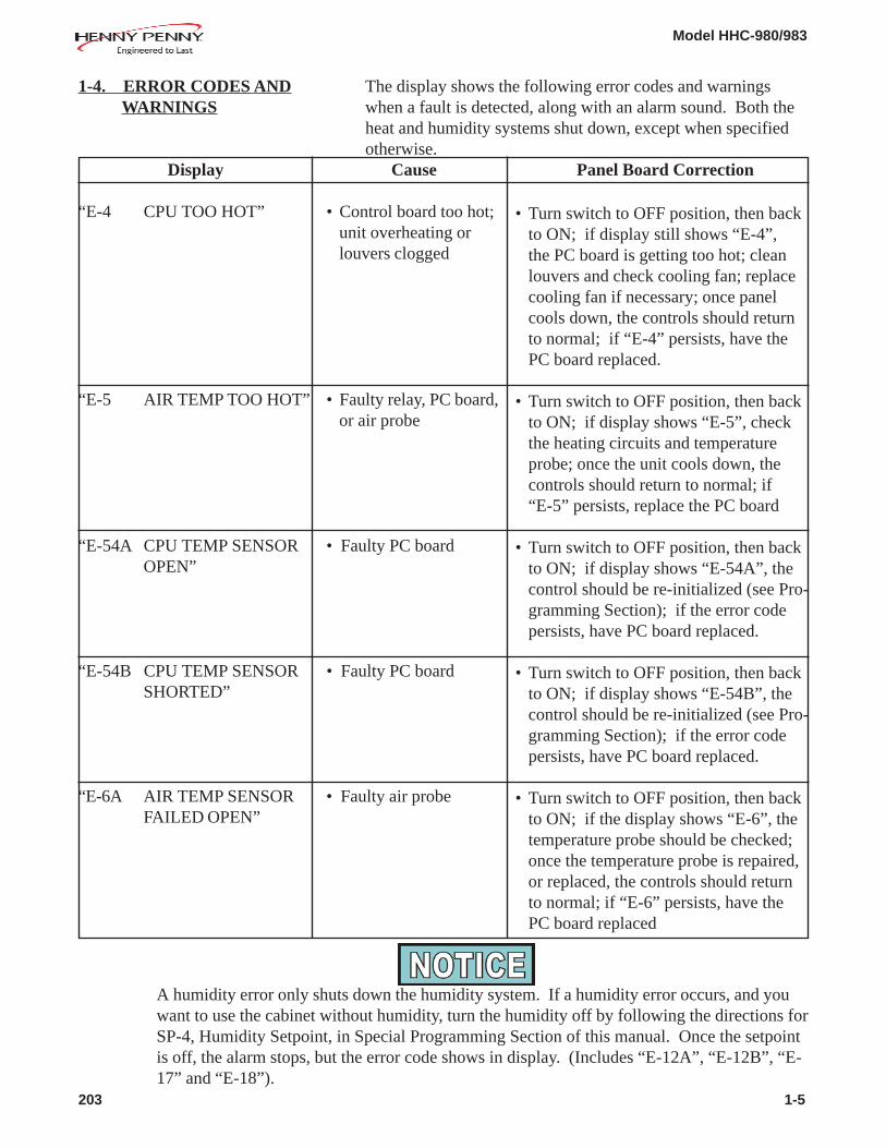
1-4. ERROR CODES AND The display shows the following error codes and warnings WARNINGS when a fault is detected, along with an alarm sound. Both the
heat and humidity systems shut down, except when specifiedotherwise.
Display Cause Panel Board Correction
“E-4 CPU TOO HOT” • Control board too hot;unit overheating orlouvers clogged
“E-5 AIR TEMP TOO HOT” • Faulty relay, PC board,or air probe
“E-54A CPU TEMP SENSOR • Faulty PC boardOPEN”
“E-54B CPU TEMP SENSOR • Faulty PC boardSHORTED”
“E-6A AIR TEMP SENSOR • Faulty air probeFAILED OPEN”
A humidity error only shuts down the humidity system. If a humidity error occurs, and youwant to use the cabinet without humidity, turn the humidity off by following the directions forSP-4, Humidity Setpoint, in Special Programming Section of this manual. Once the setpointis off, the alarm stops, but the error code shows in display. (Includes “E-12A”, “E-12B”, “E-17” and “E-18”).
203 1-5
• Turn switch to OFF position, then backto ON; if display still shows “E-4”,the PC board is getting too hot; cleanlouvers and check cooling fan; replacecooling fan if necessary; once panelcools down, the controls should returnto normal; if “E-4” persists, have thePC board replaced.
• Turn switch to OFF position, then backto ON; if display shows “E-5”, checkthe heating circuits and temperatureprobe; once the unit cools down, thecontrols should return to normal; if“E-5” persists, replace the PC board
• Turn switch to OFF position, then backto ON; if display shows “E-54A”, thecontrol should be re-initialized (see Pro-gramming Section); if the error codepersists, have PC board replaced.
• Turn switch to OFF position, then backto ON; if display shows “E-54B”, thecontrol should be re-initialized (see Pro-gramming Section); if the error codepersists, have PC board replaced.
• Turn switch to OFF position, then backto ON; if the display shows “E-6”, thetemperature probe should be checked;once the temperature probe is repaired,or replaced, the controls should returnto normal; if “E-6” persists, have thePC board replaced

Model HHC-980/983
“E-6B AIR TEMP SENSOR • Faulty air temperatureFAILED SHORTED” probe
“E-12A WATER HEATER • Faulty waterSENSOR FAILED heater probeOPEN”
“E-12B WATER HEATER • Faulty waterSENSOR FAILED heater probeCLOSED”
“E-17 HUMIDITY SENSOR • Faulty humidity sensorFAILED”
“E-18 NO WATER, FLOAT • Float switch stuck orSWITCH FAILED” faulty; faulty relay
(stuck on);water panneeds cleaned;loose or faulty waterheater sensor; acorn nutson water heater coverloose, or water heaterinsulation missing ordamaged
A humidity error only shuts down the humidity system. If a humidity error occurs, and you want touse the cabinet without humidity, turn the humidity off by following the directions for SP-4, HumiditySetpoint, in Special Programming Section of this manual. Once the setpoint is off, the alarm stops,but the error code shows in display. (Includes “E-12A”, “E-12B”, “E-17” and “E-18”).
1-4. ERROR CODES AND WARNINGS (Continued)
Display Cause Panel Board Correction• Turn switch to OFF position, then back to
ON; if the display shows “E-6”, thetemperature probe should be checked;once the temperature probe is repaired, orreplaced, the controls should return tonormal; if “E-6”persists, have PC boardreplaced
• Turn switch to OFF position, then back toON; if the display shows “E-12A”, thewater heater should be checked andrepaired or replaced (the water heaterprobe is built into the water heater); thecontrols should return to normal; if“E-12A” persists, have PC board replaced
• Turn switch to OFF position, then back toON; if the display shows “E-12B”, thewater heater should be checked andrepaired or replaced (the water heaterprobe is built into the water heater); thecontrols should return to normal; if“E-12B” persists, have PC board replaced
• Turn switch to OFF position, then back toON; if the display shows “E-17”, thehumidity sensor should be checked;once the humidity sensor is repaired, orreplaced, the controls should return tonormal; if “E-17” persists, have PC board
replaced
• Turn switch to OFF position, then back toON; if the display shows “E-18”, checkand clean float switch; clean water pan;have relay and water heater sensorchecked and replace if necessary; tightenacorn nuts on water heater cover; makesure 2 complete pieces of insulation areunder the water heater cover; if “E-18”persists, have PC board replaced
1-6 804

Model HHC-980/983
1-3. ERROR CODES AND WARNINGS (Continued)
Display Cause Panel Board Correction
“E-46 DATA SAVE FAILED” • Memory scrambled • Follow directions for SP-9, System Initialization, in Special Programming
Section of this manual; if “E-46” stillpersists, replace PC board.
“PLEASE DE-LIME • Water pan needs • Follow the weekly cleaning proceduresWATER PAN” cleaned in the Cleaning Procedures Section of
the Operator’s Manual; this warningwill not shut down the heat or humidity
“WATER LEVEL LOW, • Float switch stuck • Check float switch and replace ifPLEASE ADD WATER” or faulty; relay faulty necessary; check relay and replace if
(stuck on); water pan necessary; follow weekly cleaningneeds cleaned; loose procedures in Cleaning Proceduresor faulty water heater Section of Operator’s Manual; checksensor wires at water heater and replace water
heater if necessary (sensor is part of thewater heater)
303 1-7

Model HHC-980/983
1-4. INFO MODE This mode records historic information on the holding cabinetand operator performance, which could help in troubleshootinga problem.
Press and at the same time and “*INFO MODE*”
shows on display. Press or to access the steps andpress to view the statistics within each step.
Information Mode is intended for technical use, but the Opera-tor can view the following information:
1. Error log - last 10 errors and time they occurred2. Power up log - time of last 10 power-ups3. Outputs/Inputs - shows the state of unit’s inputs and
outputsa. OUT S_F_W_A (solenoid, fan, water heater, air
heater, relay order from left to right)b. AMPS S_F_W_A_c. NC/GD S_F_W_A_ (no connect/ground detection on
outputs to relays)d. All outputs and inputs S_F_W_A_ P_ (power switch
input) F_ (float switch input)4. CPU temperature5. Cabinet air temperature6. Water heater temperature7. Humidity counts value10. Humidity value11. Analog inputs
1-8 902
Model HHC-980/983
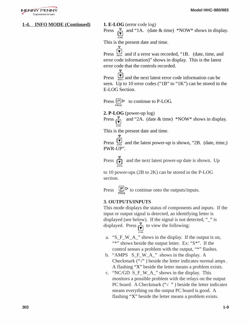
1. E-LOG (error code log)Press and “1A. (date & time) *NOW* shows in display.
This is the present date and time.
Press and if a error was recorded, “1B. (date, time, anderror code information)” shows in display. This is the latesterror code that the controls recorded.
Press and the next latest error code information can beseen. Up to 10 error codes (“1B” to “1K”) can be stored in theE-LOG Section.
Press to continue to P-LOG.
2. P-LOG (power-up log)Press and “2A. (date & time) *NOW* shows in display.
This is the present date and time.
Press and the latest power-up is shown, “2B. (date, time,)PWR-UP”.
Press and the next latest power-up date is shown. Up
to 10 power-ups (2B to 2K) can be stored in the P-LOGsection.
Press to continue onto the outputs/inputs.
3. OUTPUTS/INPUTSThis mode displays the status of components and inputs. If theinput or output signal is detected, an identifying letter isdisplayed (see below). If the signal is not detected, “_” isdisplayed. Press to view the following:
a. “S_F_W_A_” shows in the display. If the output is on,“*” shows beside the output letter. Ex: “S*”. If thecontrol senses a problem with the output, “*” flashes.
b. “AMPS S_F_W_A_” shows in the display. ACheckmark (“√” ) beside the letter indicates normal amps .A flashing “X” beside the letter means a problem exists.
c. “NC/GD S_F_W_A_” shows in the display. Thismonitors a possible problem with the relays on the outputPC board. A Checkmark (“√ ” ) beside the letter indicatesmeans everything on the output PC board is good. Aflashing “X” beside the letter means a problem exists.
1-4. INFO MODE (Continued)
303 1-9

Model HHC-980/983
1-4. INFO MODE (Continued) 3. OUTPUTS/INPUTS (Continued)d. “S_F_W_A_ P_ F_” shows in the display. If the output
or input signal is detected, “*” shows beside the letter. Ex:“S*”. If the control senses a problem with the output, “*”flashes.
Press to continue onto CPU TMP.
4. CPU TMPThis step shows the present PC board temperature.
Press to continue onto cabinet air temperature.
5. CABINET AIR TMPThis step shows the present air temperature inside the cabinet.
Press to continue onto water heater temperature.
6. WATER HEATER TMPThis step shows the present water heater temperature.
Press to continue to humidity counts value.
7. HUMIDITY COUNTS VALUEFactory use only!
Press to continue onto the humidity value.
8. HUMIDITY VALUEThis step shows the present humidity level inside the cabinet.
Press to continue onto the analog inputs.
9. ANALOG INPUTSThis step displays the present status of any channel of thecontroller’s a to d converter. This feature may be useful to atechnician troubleshooting a problem with the controller.
The displayed value can be toggled between Volts and Bits bypressing . If the displayed value has a decimal point, it is
voltage (0 to 5 VDC). If no decimal point is shown, the valueis a-to-d bits (0 - 4095).
1-10 303

Model HHC-980/983
The Tech Mode and Stats Mode in the Level 2 ProgrammingSection, have information that could help in troubleshooting aproblem with the unit.
Press and hold until “L-2 LEVEL 2”, followed by,“SP PROG”, shows in display.
Press 3 times and “TECH”, followed by, “ENTER CODE”shows in display.
Enter code, to accessthe following items:
T-1 SoftwareT-2 Cabinet versionT-3 Push button testT-4 All on display testT-5 Segments testT-6 Digits testT-7 Decimal points testT-8 LED’s testT-9 Air temperature - circuit calibration
T-10 Air temperature - user calibration/offset/highest valueT-11 Water heater temperature - circuit calibrationT-12 Water heater temperature - user calibration/offset/highest
valueT-13 Humidity - circuit calibrationT-14 Humidity sensor - calibration/offset; specific value sent
with each humidity sensorT-15 Humidity- user calibration/offset/highest valueT-16 CPU° - Control temperature - highest valueT-17 View ADC channelT-18 Outputs/inputs; on outputs steps use the following
hidden buttons [1-5] to toggle on the outputs;[2] - solenoid valve, [3] - circulation fan, [4] - waterheater, [5] - air heater.
T-19 Total init – initialization of programming areas andstatistics.
moves you forward through the above selections andmoves you backwards through the selections.
303 2-1
2-2. TECH MODE
SECTION 2. LEVEL 2 PROGRAMMING
2-1. INTRODUCTION

Model HHC-980/983
T-1: SoftwareThis section shows “PN/ID/SRL”Press . Henny Penny eprom part number is displayed.
Press . Customer ID (i.e. Pizza Hut) is displayed
Press . Software revision is displayed.
T-2: Cabinet VersionShows the model number, e.i. HHC-983
T3: Push Button TestPress any button on the control and a digital display feedbackconfirms the button is working
T4: All On Display TestPress any of the product buttons and every LED on the 16 digitdisplay lights
T5: Segments TestRepeatedly pressing any product button lights one segments inevery one of the 16 digit displays
T6: Digits TestRepeatedly pressing any product button lights all segments inone of the 16 digital displays (scrolls though all 16)
T7: Decimal Point TestRepeatedly pressing any product button lights a decimal point(DP) in one of the 16 digital displays (scrolls though all 16)
T8: LED TestRepeatedly pressing any product button lights individualLEDs (scrolls though all LEDs)
T9: Air Temperature - Circuit CalibrationFactory use only
2-2. TECH MODE (Continued)
2-2 303
Model HHC-980/983
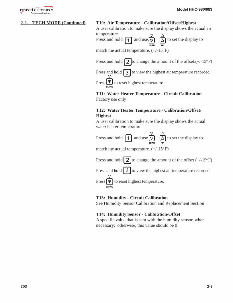
T10: Air Temperature - Calibration/Offset/HighestA user calibration to make sure the display shows the actual airtemperaturePress and hold and use to set the display to
match the actual temperature. (+/-15o F)
Press and hold to change the amount of the offset.(+/-15o F)
Press and hold to view the highest air temperature recorded.
Press to reset highest temperature.
T11: Water Heater Temperature - Circuit CalibrationFactory use only
T12: Water Heater Temperature - Calibration/Offset/HighestA user calibration to make sure the display shows the actualwater heater temperature
Press and hold and use to set the display to
match the actual temperature. (+/-15o F)
Press and hold to change the amount of the offset.(+/-15o F)
Press and hold to view the highest air temperature recorded.
Press to reset highest temperature.
T13: Humidity - Circuit CalibrationSee Humidity Sensor Calibration and Replacement Section
T14: Humidity Sensor - Calibration/OffsetA specific value that is sent with the humidity sensor, whennecessary; otherwise, this value should be 0
2-2. TECH MODE (Continued)
303 2-3

Model HHC-980/983
2-2. TECH MODE (Continued) T15: Humidity - Calibration/Offset/HighestA user calibration to make sure the display shows the actualhumidity inside the cabinet
Press and hold and use to set the display to
match the actual temperature. (+/-15o F)
Press and hold to change the amount of the offset.(+/-15o F)
Press and hold to view the highest air temperature recorded.
Press to reset highest temperature.
T16: CPUo - Control Temperature - Highest ValueShows the highest temperature the control board was exposedto
T17: View ADC ChannelFactory use only
T18: Outputs/InputsThe following components can be tested:
toggles the solenoid off and on.
toggles the cooling fan off and on.
toggles the water heater off and on.
toggles the air heaters off and on.
T19: Total InitializationCompletely resets any accumulated information and changedsettings in the controls; contact Henny Penny Corp. beforecompleting this step!
2-4 303

Model HHC-980/983
2-3. STATS MODE Press and hold until “L-2 LEVEL 2”, followed by,
“SP PROG”, shows in display.
Press 4 times and “STATS”, followed by, “ENTERCODE” shows in display.
Enter code, to accessthe following items:
ST-1 Power live hoursST-2 Power on hoursST-3 Power-ups countST-4 Errors countST-5 Air heat on hoursST-6 Water heater on hoursST-7 Circulation fan on hoursST-8 Water solenoid on hoursST-9 Solenoid cycle count
ST-10 Longest solenoid on time; maximum=5 minutesST-11 Highest air temperatureST-12 Highest water heater temperatureST-13 Highest humidity valueST-14 Highest CPU temperatureST-15 Water heater (too hot) cycle countST-16 Sys ram – Fade countST-17 Hold RAM – Fade countST-18 Stat RAM – Fade countST-19 Ram data error countST-20 Data total loss countST-21 User init’s countST-22 Auto init’s countST-23 Error logST-24 Power up logST-25 Heat up logST-26 Reset all stats
moves you forward through the above selections andmoves you backwards through the selections.
303 2-5
Model HHC-980/983
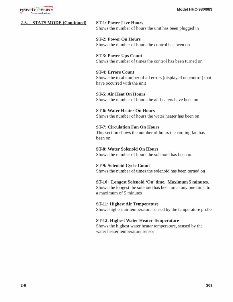
2-3. STATS MODE (Continued) ST-1: Power Live HoursShows the number of hours the unit has been plugged in
ST-2: Power On HoursShows the number of hours the control has been on
ST-3: Power Ups CountShows the number of times the control has been turned on
ST-4: Errors CountShows the total number of all errors (displayed on control) thathave occurred with the unit
ST-5: Air Heat On HoursShows the number of hours the air heaters have been on
ST-6: Water Heater On HoursShows the number of hours the water heater has been on
ST-7: Circulation Fan On HoursThis section shows the number of hours the cooling fan hasbeen on.
ST-8: Water Solenoid On HoursShows the number of hours the solenoid has been on
ST-9: Solenoid Cycle CountShows the number of times the solenoid has been turned on
ST-10: Longest Solenoid ‘On’ time. Maximum 5 minutes.Shows the longest the solenoid has been on at any one time, toa maximum of 5 minutes
ST-11: Highest Air TemperatureShows highest air temperature sensed by the temperature probe
ST-12: Highest Water Heater TemperatureShows the highest water heater temperature, sensed by thewater heater temperature sensor
2-6 303

Model HHC-980/983
2-3. STATS MODE (Continued) ST-13: Highest Humidity ValueShows the highest humidity value sensed by the humiditysensor
ST-14: Highest CPU TemperatureShows the highest control board temperature sensed by thecontrol
ST-15: Water heater (too hot) cycle countShows the number of times the water heater has gotten too hot
ST-16: System Ram - Fade CountShows the number of times the system memory has been lostduring power up; ex: oF or oC, or speaker volume
ST-17: Hold Ram - Fade CountShows the number of times the hold memory has been lostduring a power up; may be lost at a power up, after a powerloss, during a holding cycle
ST-18: Stat Ram - Fade CountThis section shows the number of times the Stats memory hasbeen lost during power up; the information in the Stats Modeis updated every two hours, and this count lets you know thatthe updates were lost
ST-19: Ram Data Error CountShows the number of times the data was lost while operating,not during power up (should be a low number)
ST-20: Data Total Loss CountShows the number of times the data stored in the Eprom hasbeen lost; should see an “E-41” error code when this occurs
ST-21: User Init’s CountShows the number of times the operator has initialized thecontrols
ST-22: Auto Init’s CountShows the number of times the controls have automaticallyreset
ST-23: Error LogRecords the last 10 errors and the time they occurred; press to view the log
303 2-7

Model HHC-980/983
ST-24: Power Up LogRecords the last 10 power ups and when they occurred; press to view the log
ST-25: Heat Up LogRecords the last 10 heat ups between 250o F (121o C) to 300o F(149o C), when they occurred, and how long (seconds) it took;press to view the log
ST-26: Resets All StatsAllows the user to reset all data stored in the Stats Mode; pressand hold for 3 seconds
The Data Logging and Manufacturing Modes are mainly forHenny Penny use only. For more information on these modes,contact the Service Department at 1-800-417- 8405, or1-937-456-8405.
2-3. STATS MODE (Continued)
2-4. DATA LOGGING AND MANUFACTURING MODE
2-8 303

Model HHC-980/983
This section provides procedures for the checkout and re-placement of the various parts used within the merchandiser.Before replacing any parts, refer to the Troubleshooting sec-tion. It will aid you in determining the cause of the malfunc-tion.
1. You may want to use a multimeter to check the electriccomponents.
2. When the manual refers to the circuit being closed, themultimeter should read zero unless otherwise noted.
3. When the manual refers to the circuit being open, the multi-meter reads infinity.
The Humidity Sensor relays the cabinet humidity to the controls.If it becomes faulty, “E-17”, then “HUMIDITY SENSORFAILED” shows on the display. Replace sensor as follows:
To avoid electrical shock or property damage, move thepower switch to OFF and disconnect main circuitbreaker, or unplug cord at wall receptacle.
1. Open top, operator side door of full-size units, or operatordoor of 1/2 size units.
2. Using a Phillip’s head screwdriver, remove the front screwand loosen the 2 side screws securing the sensor cover.Slide cover towards you and off loosened screws.Figure 3-1
3. Using a Phillip’s head screwdriver, remove the 4 screwssecuring the sensor to the box. Figure 3-2.
SECTION 3. MAINTENANCE
3-1. INTRODUCTION
3-2. MAINTENANCE HINTS
3-3. HUMIDITY SENSOR CALIBRATION AND REPLACEMENT
Figure 3-1
Figure 3-2
303 3-1
Replacement:

Model HHC-980/983
3-3. HUMIDITY SENSOR CALIBRATION AND REPLACEMENT (Continued)
4. Pull the sensor assembly from the box and disconnect thewires. Figure 3-3.
5. Connect wires of new sensor and attach the sensor to thebox. Follow the calibration instructions below before re-attaching the sensor cover.
6. Once the calibration is complete, slide the cover over thePhillip’s head screws and tighten. Unit is now ready foruse.
Calibration:Calibrate the humidity sensor after a sensor or control replace-ment. A calibration board is supplied with each control kit andhumidity sensor kit, but can also be ordered separately withpart number, 14391.
1. If not already done, open the cabinet door, and remove thehumidity sensor cover at top of unit. (See step 2, page 3-1.)
2. While holding the white tube, unscrew the silver cap fromthe humidity sensor.
3. Remove the two pronged sensor by grasping the edges.Figure 3-4.
Use caution not to touch the flat edge, as it will throw thereading off.
4. Push and hold until “Level 2” appears in display.
5. Press to step through the menu until “TECH’ isdisplayed.
Figure 3-3
Figure 3-4
3-2 303

Model HHC-980/983
3-3. HUMIDITY SENSOR CALIBRATION AND REPLACEMENT (Continued)
6. Using the hidden buttons, (Figure 3-5), enter code of11221122. (Hidden buttons 1 through 5 left to right)
7. Press to step through menu to step 13.
8. Insert the two prongs of the calibration board marked 20%into the humidity sensor. Figure 3-6.
9. Press and hold the hidden button , then press .Release both buttons. 20% should then show in display.
10. Reverse calibration board and insert the two prongs marked80% into humidity sensor.
11. Push and hold the hidden button then press .Release both buttons. 80% should then show in display.
12. Push the (P) button to step 14 on models 983 & 980, or tostep 16 on models 993, 990, 996, & 998.
13. Find the offset number on the mounting plate of the humiditysensor.
When changing the control board on units with serial numberIV178JB and below, no offset will be found. Leave offset at 0.
14. Push and hold the hidden button “2”, then push the UP orDOWN arrows to enter the offset number.
12. Press and hold to exit TECH mode.
13. Reinstall two pronged sensor into humidity sensor.
14. Reinstall silver cap and sensor cover, and unit is now readyfor use.
Figure 3-5
Figure 3-6
303 3-3

Model HHC-980/983
3-4. FUSE AND FUSE HOLDER ASSEMBLY
If the unit (non-CE) is completely inoperative, but power existsat the wall receptacle, check the 15 amp fuse(s) and fuseholder(s) as follows:
To avoid electrical shock or property damage, move thepower switch to OFF and disconnect main circuitbreaker, or unplug cord at wall receptacle.
1. Unscrew the fuse holder cap by turning it counterclock-wise. (Located under the power cord.) Figure 3-7.
2. Pull the fuse from the cap and check for continuity byplacing the leads of a multimeter or continuity light onopposite ends of the fuse. The fuse should show closed orread no resistance. If fuse is defective, replace it with anew one. Be sure replacement fuse is identical to the onebeing replaced. (208 or 240 volt units have 2 fuses andboth should be checked.)
If fuses show good, the fuse holders may be bad. Check thefuse holders as follows:
To avoid electrical shock or property damage, move thepower switch to OFF and disconnect main circuitbreaker, or unplug cord at wall receptacle.
1. Remove the screws securing the rear access panel and pullpanel down.
2. Remove the wires from the fuse holder, and check forcontinuity by placing the leads of a multimeter or continu-ity light on terminals of the fuse holder. The fuse holdershould show closed or read no resistance. Figure 3-8.
3. If fuse holder shows it’s defective, remove the screwssecuring it to the panel and replace it with a new one.Figure 3-9.
4. Reinstall the rear panel and make sure the fuse holder has a15 amp fuse in it.
5. Restore power to the cabinet and it’s now ready for use.
Figure 3-7
Checking Fuse Holder(s)
Figure 3-8
Figure 3-9
3-4 303
Checking Fuse(s)

Model HHC-980/983
3-5. POWER SWITCH REPLACEMENT
To avoid electrical shock or property damage, move thepower switch to OFF and disconnect main circuitbreaker, or unplug cord at wall receptacle.
1. Using a Phillip’s head screwdriver, remove the four screwssecuring the front panel.
2. Pull panel down, pull connectors from the back of it, andremove panel from unit.
3. Using 5/16” socket, remove the 4 nuts securing the controlcover and remove cover. Figure 3-10.
4. Pull wires from switch and check across the 2 terminals forcontinuity. Figure 3-11. With switch in ON position, thecircuit should be closed. In the OFF position the circuitshould be open. If the switch is defective, continue withstep 5.
5. Pinch the tabs on the rear of the switch and pull the switchthrough the front of the panel. Figure 3-12.
6. Replace with new switch in reverse order and unit is nowready for use.
Figure 3-10
Figure 3-11
Figure 3-12
303 3-5

Model HHC-980/983
3-6. AIR TEMPERATURE PROBE REPLACEMENT
To avoid electrical shock or property damage, move thepower switch to OFF and disconnect main circuitbreaker, or unplug cord at wall receptacle.
1. Using a Phillip’s head screwdriver, remove the four screwssecuring the front panel.
2. Pull panel down, pull connectors from the back of it, andremove panel from unit.
3. Unplug the wires to the probe. Figure 3-13.
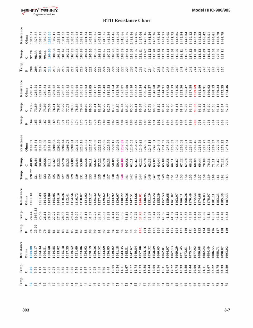
4. Using a multimeter, or ohmmeter, check across the probeterminals for the correct ohms using the RTD ResistanceChart on the following page. If the probe proves faulty,continue onto step 5.
5. Using a 3/4” wrench, loosen probe strain relief and pullthe probe from the unit. Figure 3-14.
6. Slide new probe through the strain relief, extending theprobe about 1” (25.4 mm) into the cabinet area.Figure 3-15.
7. Plug probe wires to the unit, tighten the strain relief, andreplace front panel. Unit is now ready for use.
Figure 3-13
Figure 3-14
Figure 3-15
3-6 303
Model HHC-980/983
RTD Resistance ChartT
emp
.T
emp
.R
esis
tan
ce
FC
Oh
ms
32
0.00
1000
.00
33
0.56
1002
.17
34
1.11
1004
.34
35
1.67
1006
.51
36
2.22
1008
.68
37
2.78
1010
.85
38
3.33
1013
.02
39
3.89
1015
.18
40
4.44
1017
.35
41
5.00
1019
.52
42
5.56
1021
.69
43
6.11
1023
.86
44
6.67
1026
.02
45
7.22
1028
.19
46
7.78
1030
.36
47
8.33
1032
.52
48
8.89
1034
.69
49
9.44
1036
.85
50
10.0
010
39.0
25
110
.56
1041
.18
52
11.1
110
43.3
55
311
.67
1045
.51
54
12.2
210
47.6
75
512
.78
1049
.84
56
13.3
310
52.0
05
713
.89
1054
.16
58
14.4
410
56.3
25
915
.00
1058
.49
60
15.5
610
60.6
56
116
.11
1062
.81
62
16.6
710
64.9
76
317
.22
1067
.13
64
17.7
810
69.2
96
518
.33
1071
.45
66
18.8
910
73.6
16
719
.44
1075
.77
68
20.0
010
77.9
26
920
.56
1080
.08
70
21.1
110
82.2
47
121
.67
1084
.40
72
22.2
210
86.5
57
322
.78
1088
.71
74
23.3
310
90.8
77
523
.89
1093
.02
Tem
p.
Tem
p.
Res
ista
nce
FC
Oh
ms
76
24.4
410
95.1
87
725
.00
1097
.33
78
25.5
610
99.4
97
926
.11
1101
.64
80
26.6
711
03.8
08
127
.22
1105
.95
82
27.7
811
08.1
08
328
.33
1110
.26
84
28.8
911
12.4
18
529
.44
1114
.56
86
30.0
011
16.7
28
730
.56
1118
.87
88
31.1
111
21.0
28
931
.67
1123
.17
90
32.2
211
25.3
29
132
.78
1127
.47
92
33.3
311
29.6
29
333
.89
1131
.77
94
34.4
411
33.9
29
535
.00
1136
.07
96
35.5
611
38.2
29
736
.11
1140
.36
98
36.6
711
42.5
19
937
.22
1144
.66
100
37.7
811
46.8
110
138
.33
1148
.95
102
38.8
911
51.1
010
339
.44
1153
.24
104
40.0
011
55.3
910
540
.56
1157
.53
106
41.1
111
59.6
810
741
.67
1161
.82
108
42.2
211
63.9
710
942
.78
1166
.11
110
43.3
311
68.2
611
143
.89
1170
.40
112
44.4
411
72.5
411
345
.00
1174
.68
114
45.5
611
76.8
311
546
.11
1178
.97
116
46.6
711
81.1
111
747
.22
1183
.25
118
47.7
811
85.3
911
948
.33
1187
.53
Tem
p.
Tem
p.
Res
ista
nce
FC
Oh
ms
120
48.8
911
89.6
712
149
.44
1191
.81
122
50.0
011
93.9
512
350
.56
1196
.09
124
51.1
111
98.2
312
551
.67
1200
.36
126
52.2
212
02.5
012
752
.78
1204
.64
128
53.3
312
06.7
812
953
.89
1208
.91
130
54.4
412
11.0
513
155
.00
1213
.18
132
55.5
612
15.3
213
356
.11
1217
.45
134
56.6
712
19.5
913
557
.22
1221
.72
136
57.7
812
23.8
613
758
.33
1225
.99
138
58.8
912
28.1
213
959
.44
1230
.26
140
60.0
012
32.3
914
160
.56
1234
.52
142
61.1
112
36.6
514
361
.67
1238
.79
144
62.2
212
40.9
214
562
.78
1243
.05
146
63.3
312
45.1
814
763
.89
1247
.31
148
64.4
412
49.4
414
965
.00
1251
.57
150
65.5
612
53.7
015
166
.11
1255
.83
152
66.6
712
57.9
515
367
.22
1260
.08
154
67.7
812
62.2
115
568
.33
1264
.34
156
68.8
912
66.4
615
769
.44
1268
.59
158
70.0
012
70.7
215
970
.56
1272
.84
160
71.1
112
74.9
716
171
.67
1277
.09
162
72.2
212
79.2
216
372
.78
1281
.34
Tem
p.
Tem
p.
Res
ista
nce
FC
Oh
ms
164
73.3
312
83.4
716
573
.89
1285
.59
166
74.4
412
87.7
116
775
.00
1289
.84
168
75.5
612
91.9
616
976
.11
1294
.08
170
76.6
712
96.2
017
177
.22
1298
.32
172
77.7
813
00.4
517
378
.33
1302
.57
174
78.8
913
04.6
917
579
.44
1306
.81
176
80.0
013
08.9
317
780
.56
1311
.05
178
81.1
113
13.1
717
981
.67
1315
.28
180
82.2
213
17.4
018
182
.78
1319
.52
182
83.3
313
21.6
418
383
.89
1323
.76
184
84.4
413
25.8
718
585
.00
1327
.99
186
85.5
613
30.1
018
786
.11
1332
.22
188
86.6
713
34.3
418
987
.22
1336
.45
190
87.7
813
38.5
719
188
.33
1340
.68
192
88.8
913
42.7
919
389
.44
1344
.91
194
90.0
013
47.0
219
590
.56
1349
.13
196
91.1
113
51.2
519
791
.67
1353
.36
198
92.2
213
55.4
719
992
.78
1357
.58
200
93.3
313
59.6
920
193
.89
1361
.80
202
94.4
413
63.9
120
395
.00
1366
.02
204
95.5
613
68.1
320
596
.11
1370
.24
206
96.6
713
72.3
520
797
.22
1374
.46
Tem
p.
Tem
p.
Res
ista
nce
FC
Oh
ms
208
97.7
813
76.5
720
998
.33
1378
.68
210
98.8
913
80.7
921
199
.44
1382
.89
212
100.
0013
85.0
021
310
0.56
1387
.11
214
101.
1113
89.2
121
510
1.67
1391
.32
216
102.
2213
93.4
221
710
2.78
1395
.53
218
103.
3313
97.6
321
910
3.89
1399
.74
220
104.
4414
01.8
422
110
5.00
1403
.95
222
105.
5614
06.0
522
310
6.11
1408
.15
224
106.
6714
10.2
522
510
7.22
1412
.36
226
107.
7814
14.4
622
710
8.33
1416
.56
228
108.
8914
18.6
622
910
9.44
1420
.76
230
110.
0014
22.8
623
111
0.56
1424
.96
232
111.
1114
27.0
623
311
1.67
1429
.16
234
112.
2214
31.2
623
511
2.78
1433
.36
236
113.
3314
35.4
623
711
3.89
1437
.55
238
114.
4414
39.6
523
911
5.00
1441
.75
240
115.
5614
43.8
524
111
6.11
1445
.94
242
116.
6714
48.0
424
311
7.22
1450
.13
244
117.
7814
52.2
324
511
8.33
1454
.32
246
118.
8914
56.4
224
711
9.44
1458
.51
248
120.
0014
60.6
124
912
0.56
1462
.70
250
121.
1114
64.7
9
303 3-7

Model HHC-980/983
3-7. TRANSFORMER REPLACEMENT
To avoid electrical shock or property damage, move thepower switch to OFF and disconnect main circuitbreaker, or unplug cord at wall receptacle.
1. Using a Phillip’s head screwdriver, remove the four screwssecuring the front panel.
2. Pull panel down, pull connectors from the back of it, andremove panel from unit.
3. Label wires to transformer and unplug wires to trans-former. Figure 3-16.
4. Using a Phillip’s head screwdriver, remove the 2 screwssecuring the transformer and pull transformer from unit.Figure 3-17.
5. Install new transformer in reverse order and unit is nowready for use.
Figure 3-16
Figure 3-17
3-8 303

Model HHC-980/983
3-8. RELAY REPLACEMENT
To avoid electrical shock or property damage, move thepower switch to OFF and disconnect main circuitbreaker, or unplug cord at wall receptacle.
1. Using a Phillip’s head screwdriver, remove the four screwssecuring the front panel.
2. Pull panel down, pull connectors from the back of it, andremove panel from unit.
The following checks are performed with the wallcircuit breaker closed and the main power switch in theON position. Extreme caution should be taken. Makeconnections before applying power, take reading, andremove power before removing meter leads, or electri-cal shock could result.
3. With power reapplied, let unit start heating up, or enterthe Tech Mode in Special Program Mode and check therelays in the output test. (See T-18 in the Tech ModeSection)
4. With the component energized (example: air heaters), 0 voltsshould show on the output side of the relay, and 12 volts onthe input side.
5. With the component not energized, 208 or 240 voltsshould show on the output side of relay, and 0 volts oninput.
6. If voltage varies from steps 4 and 5, remove power tounit, pull input wires from relay and place leads ofmeter onto input wires. Reapply power to unit. Whenunit is running, the input wires to relay should show 12 vdcvolts. If this proves true, the relay is faulty and continueonto step 7.
Checkout:
303 3-9

Model HHC-980/983
3-8. RELAY REPLACEMENT (Continued)
7. Label wires and then remove wires from relay using aPhillip’s head screwdriver. Figure 3-18.
8. Using a Phillip’s head screwdriver, remove the 2 screwssecuring the relay and remove relay from unit. Figure 3-19.
9. Coat the back of the relay with the thermal jointcompound.
Failure to use the thermal joint compound will shorten thelife of the relay.
10. Install new relay in reverse order and unit is now ready foruse.
To avoid electrical shock or property damage, move thepower switch to OFF and disconnect main circuitbreaker, or unplug cord at wall receptacle.
1. Using a Phillip’s head screwdriver, remove the modulescrews from the side. Figure 3-20.
2. Remove screws from front and rear panels.
3. Pull module top from module. Figure 3-21.
Figure 3-18
Figure 3-19
3-9. MODULE TOP REMOVAL
Figure 3-20
3-10 303
Figure 3-21

Model HHC-980/983
3-10. COOLING FAN REPLACEMENT
To avoid electrical shock or property damage, move thepower switch to OFF and disconnect main circuit breaker,or unplug cord at wall receptacle.
1. Refer to section 3-10 for module top removal.
2. Unplug connectors to the cooling fan. Figure 3-22.
3. Remove screws and nuts securing the fan and remove fanfrom module. Figure 3-23.
4. Install new fan in reverse order and unit is now ready for use.
To avoid electrical shock or property damage, move thepower switch to OFF and disconnect main circuit breaker,or unplug cord at wall receptacle.
1. Follow the instructions in section 3-10 on removing themodule top.
2. Remove wires from high limit. Figure 3-24.
3. Check across the terminals for continuity. If the unit is notheating, the circuit should be closed, or read no resistance. Ifhigh limit is defective, continue onto step 4.
4. Remove the 2 screws securing the high limit and remove highlimit. Figure 3-25.
5. Install new high limit in reverse order and unit is now readyfor use.
Figure 3-22
Figure 3-23
Figure 3-24
3-11. HIGH LIMIT-AIR HEATER REPLACEMENT
Figure 3-25
303 3-11

Model HHC-980/983
3-12. BLOWER MOTOR REPLACEMENT
To avoid electrical shock or property damage, movethe power switch to OFF and disconnect maincircuit breaker, or unplug cord at wall receptacle.
1. Follow the instructions in section 3-10 on removing themodule top.
2. Unplug wires to blower motor. Figure 3-26.
3. Using a Phillip’s head screwdriver, remove the screwssecuring the blower bracket to the module. Figure 3-27.
4. Pull bracket from module. Loosen set screw on fanblade and pull blade from blower. Figure 3-28.
5. Remove the 3 nuts securing the blower to the bracketand remove blower motor. Figure 3-29.
6. Install new blower in reverse order, and unit is nowready for use.
Figure 3-26
Figure 3-27
Figure 3-28
Figure 3-29
3-12 303

Model HHC-980/983
3-13. AIR HEATER REPLACEMENT
To avoid electrical shock or property damage, move thepower switch to OFF and disconnect main circuitbreaker, or unplug cord at wall receptacle.
1. Follow the instructions in section 3-10 on removing themodule top.
2. Unplug the wires to the heater and high limit. Figure 3-30.
3. Using a Phillip’s head screwdriver, remove the 4 screwssecuring the heater and remove heater. Figure 3-31.
4. Install new heater in reverse order and unit is now readyfor use.
To avoid electrical shock or property damage, move thepower switch to OFF and disconnect main circuitbreaker, or unplug cord at wall receptacle.
1. Remove the 4 screws securing the front panel.
2. Pull connectors from back of panel and remove panel.
3. Unplug wires to speaker. Figure 3-32.
4. Using a Phillip’s head screwdriver, remove the screwssecuring the speaker and remove speaker. Figure 3-33.
5. Install new speaker in reverse order and unit is now readyfor use.
Figure 3-30
Figure 3-31
3-14. SPEAKER REPLACEMENT
Figure 3-32
Figure 3-33
303 3-13

Model HHC-980/983
3-15. COMPLETE PANEL OR PC BOARD REPLACEMENT
To avoid electrical shock or property damage, move thepower switch to OFF and disconnect main circuitbreaker, or unplug cord at wall receptacle.
The complete control panel assembly can be replaced, or justthe PC board. Follow steps 1 & 2 for the complete panel andcontinue with the remaining steps for the PC Board replace-ment.
1. Remove the 4 screws securing the front panel.
2. Pull connectors from back of panel and remove panel.Figure 3-34 Install complete panel in reverse order. Wheninstalling the PC board, continue to step 3.
3. Using 5/16” socket, remove the 4 nuts securing the controlcover and remove cover. Figure 3-35.
4. Pull the connectors from PC Board. Figure 3-36.
5. Using 5/16” socket, remove the 8 nuts securing the PCboard and remove board. Figure 3-37.
6. Install new PC board in reverse order and unit is now readyfor use.
Figure 3-34
Figure 3-35
Figure 3-36
3-14 903
Figure 3-37

Model HHC-980/983
3-16. FLOAT SWITCH REPLACEMENT
To avoid electrical shock or property damage, move thepower switch to OFF and disconnect main circuitbreaker, or unplug cord at wall receptacle.
1. Disconnect water supply at side of cabinet. Open drainvalve and empty water pan into a shallow pan or floordrain. Figure 3-38.
Hot water! Do not place your hand under thedrain while draining the unit. Failure to follow thiswarning could result in severe burns and injury.
2. Unplug wires to float switch. Figure 3-39.
3. Remove nut securing the float switch and pull float switchfrom unit. Figure 3-40.
4. Install new float switch in reverse order, making sure floatswitch is in upright position. Figure 3-41.
5. Reconnect water supply and unit is now ready for use..
Figure 3-38
Figure 3-39
Figure 3-40
Figure 3-41
303 3-15

Model HHC-980/983
3-17. HIGH LIMIT - WATER HEATER REPLACEMENT
To avoid electrical shock or property damage, move thepower switch to OFF and disconnect main circuit breaker,or unplug cord at wall receptacle.
1. Disconnect water supply at side of cabinet. Open drain valveand empty water pan into a shallow pan or floor drain.Figure 3-42.
Hot water! Do not place your hand under thedrain while draining the unit. Failure to follow thiswarning could result in severe burns and injury.
2. Remove all doors and racks from unit and carefully lay theunit on its back. (This step may not be necessary for units onstands.)
3. Using an 11/32” socket or wrench, remove the nuts securingthe water heater cover and remove cover. Figure 3-43.
4. Remove wire from high limit. Figure 3-44.
5. Check across the terminals for continuity. If the unit is notheating, the circuit should be closed, or read no resistance. Ifhigh limit is defective, continue onto step 6.
6. Remove the 2 nuts securing the high limit and remove highlimit.
7. Install new high limit in reverse order.
8. Reconnect water supply and unit is now ready for use.
3-16 303
Figure 3-42
Figure 3-43
Figure 3-44

Model HHC-980/983
3-18. WATER HEATER REPLACEMENT
Figure 3-45
Figure 3-46
Figure 3-47
Figure 3-48
1006 3-17
To avoid electrical shock or property damage, move thePOWER switch to OFF and disconnect main circuit breaker,or unplug cord at wall receptacle.
1. Open drain valve and empty water pan into a shallow pan or floordrain. (See Figure 3-42 on page 3-16.)
Hot water! Do not place your hand under thedrain while draining the unit. Failure to follow thiswarning could result in severe burns and injury.
2. Remove all doors and racks from unit and carefully lay the unit onits back. (This step may not be necessary for units on stands.)
3. Using an 11/32” socket or wrench, remove the nuts securing thewater heater cover and remove cover. (See Figure 3-43on page 3-16.)
4. Unplug water heater and high limit wires. Figure 3-45.
5. Remove the nuts securing the water heater plate and high limit,and pull high limit, plate, insulation and water pan heater from theunit. Figure 3-46.
6. Pull plate and insulation from unit and discard plate and insulation.Figure 3-47.
7. Pull water heater from unit. Figure 3-48.

Model HHC-980/983
8. Locate the aluminum, octagon plate in the kit. Make sure thesurface is free of debris and place the plate over the 4 long studs.Figure 3-49.
9. Install new heater, making sure the flat side is towards the plateand the soldered wires are exposed, as shown in Figure 3-50.
10. Install the new insulation from the kit, over the water pan heater.Figure 3-51.
11. Place new cover plate from the kit, over the insulation.Figure 3-52.
12. Locate the 12 keps nuts from the kit and place them over thestuds and finger-tighten. Using an 11/32” socket or wrench, snugthe nuts down in a cross-fashion, but DO NOT overtighten.
Overtightening the nuts could damage the coating on the heater,causing the heater to fail prematurely.
13. Reinstall high limit.
14. Reconnect high limit wires and water pan heater wires to unit.
15. Reinstall water heater cover and water supply, and unit is nowready for use.
Figure 3-49
Figure 3-50
Figure 3-51
Figure 3-52
3-18. WATER HEATER REPLACEMENT (Continued)
3-18 1006

Model HHC-980/983
3-19. DRAIN VALVE REPLACEMENT
To avoid electrical shock or property damage, move thepower switch to OFF and disconnect main circuit breaker,or unplug cord at wall receptacle.
1. Disconnect water supply at side of cabinet. Open drain valveand empty water pan into a shallow pan or floor drain.(See Figure 3-42 on page 3-16.)
Hot water! Do not place your hand under thedrain while draining the unit. Failure to follow thiswarning could result in severe burns and injury.
2. Remove all doors and racks from unit and carefully lay theunit on its back. (This step may not be necessary for units onstands.)
3. Loosen hose clamp on water hose and pull hose from waterstrainer.
4. Turn drain valve handle to open position (pointed outwards).
5. Using 2 wrenches, turn drain valve counterclockwise, whileholding fitting behind it. Figure 3-53. Remove drain valveassembly from unit.
6. Remove elbow from valve.
7. Put pipe sealant on threads of elbow and install elbow in newdrain valve.
8. Put pipe sealant on threads of fitting, and install new drainvalve assembly onto fitting.
9. Reconnect water supply and unit is now ready for use.
Figure 3-53
303 3-19

Model HHC-980/983
1. Disconnect water supply at side of cabinet.
2. Remove the hex cap at the bottom of the water strainer.Figure 3-54.
3. Remove the screen from inside the strainer and clean.Figure 3-55. If lime has built up on the strainer, clean with limeremover.
4. Reassemble in reverse order.
5. Reconnect water supply and check for leaks. If no leaks arefound, unit is now ready for use.
3-20. CLEANING WATER STRAINER
Figure 3-54
Figure 3-55
3-21. WATER VALVE (SOLENOID) REPLACEMENT
To avoid electrical shock or property damage, move thepower switch to OFF and disconnect main circuit breaker,or unplug cord at wall receptacle.
1. Disconnect water supply at side of cabinet. Open drain valveand empty water pan into a shallow pan or floor drain.(See Figure 3-42 on page 3-16.)
3-20 303

Model HHC-980/983
Hot water! Do not place your hand under thedrain while draining the unit. Failure to follow thiswarning could result in severe burns and injury.
2. Remove all doors and racks from unit and carefully lay theunit on its back. (This step may not be necessary for unitson stands.)
3. Using a Phillip’s head screwdriver, remove the screwssecuring the solenoid to the cover. Figure 3-56.
4. Using a Phillip’s head screwdriver, remove the screwssecuring the cover and remove cover. Figure 3-57.
5. Unplug the wires to the solenoid. Figure 3-58.
6. Loosen hose clamps and pull hoses from solenoid and thestrainer. Figure 3-59.
3-21. WATER VALVE (SOLENOID) REPLACEMENT (Continued)
Figure 3-56
Figure 3-57
Figure 3-58
Figure 3-59
303 3-21
Model HHC-980/983
3-21. WATER VALVE (SOLENOID) REPLACEMENT (Continued)
3-22. DOOR GASKET REPLACEMENT
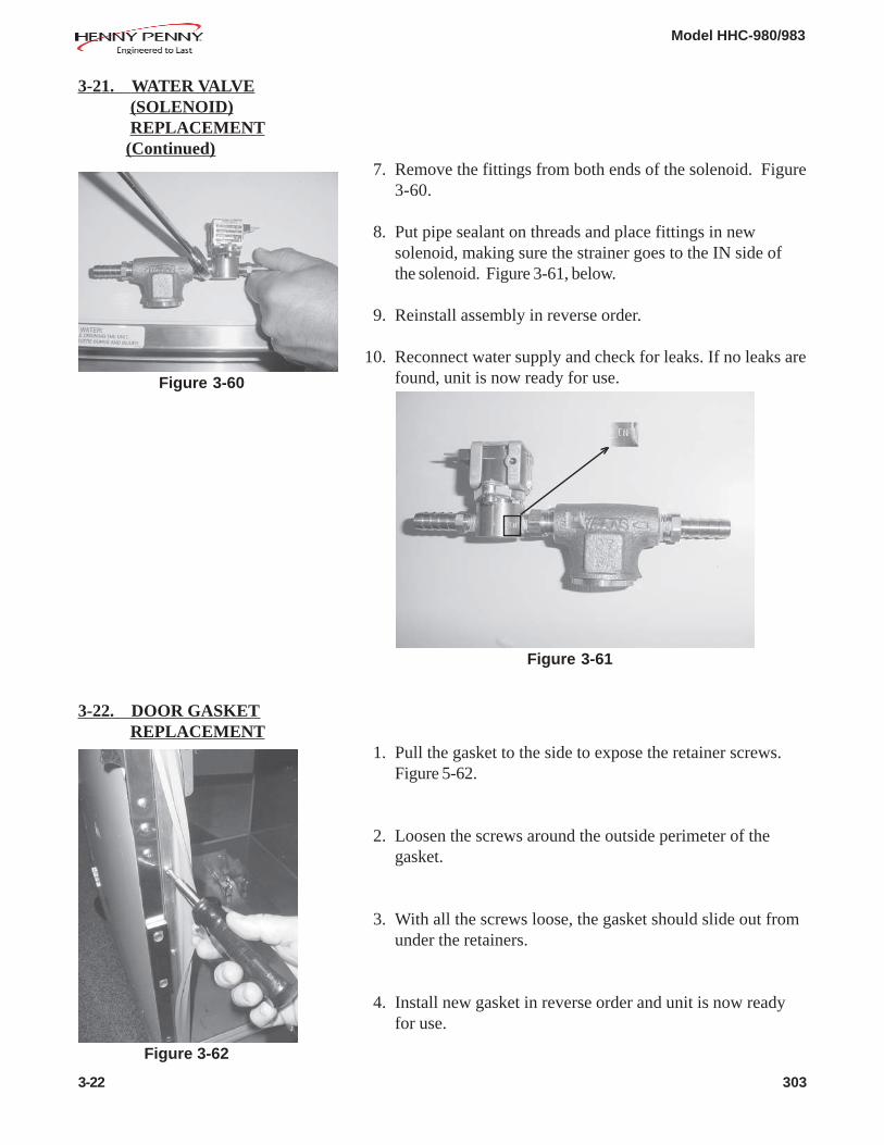
7. Remove the fittings from both ends of the solenoid. Figure3-60.
8. Put pipe sealant on threads and place fittings in newsolenoid, making sure the strainer goes to the IN side ofthe solenoid. Figure 3-61, below.
9. Reinstall assembly in reverse order.
10. Reconnect water supply and check for leaks. If no leaks arefound, unit is now ready for use.
1. Pull the gasket to the side to expose the retainer screws.Figure 5-62.
2. Loosen the screws around the outside perimeter of thegasket.
3. With all the screws loose, the gasket should slide out fromunder the retainers.
4. Install new gasket in reverse order and unit is now readyfor use.
3-22 303
Figure 3-60
Figure 3-61
Figure 3-62
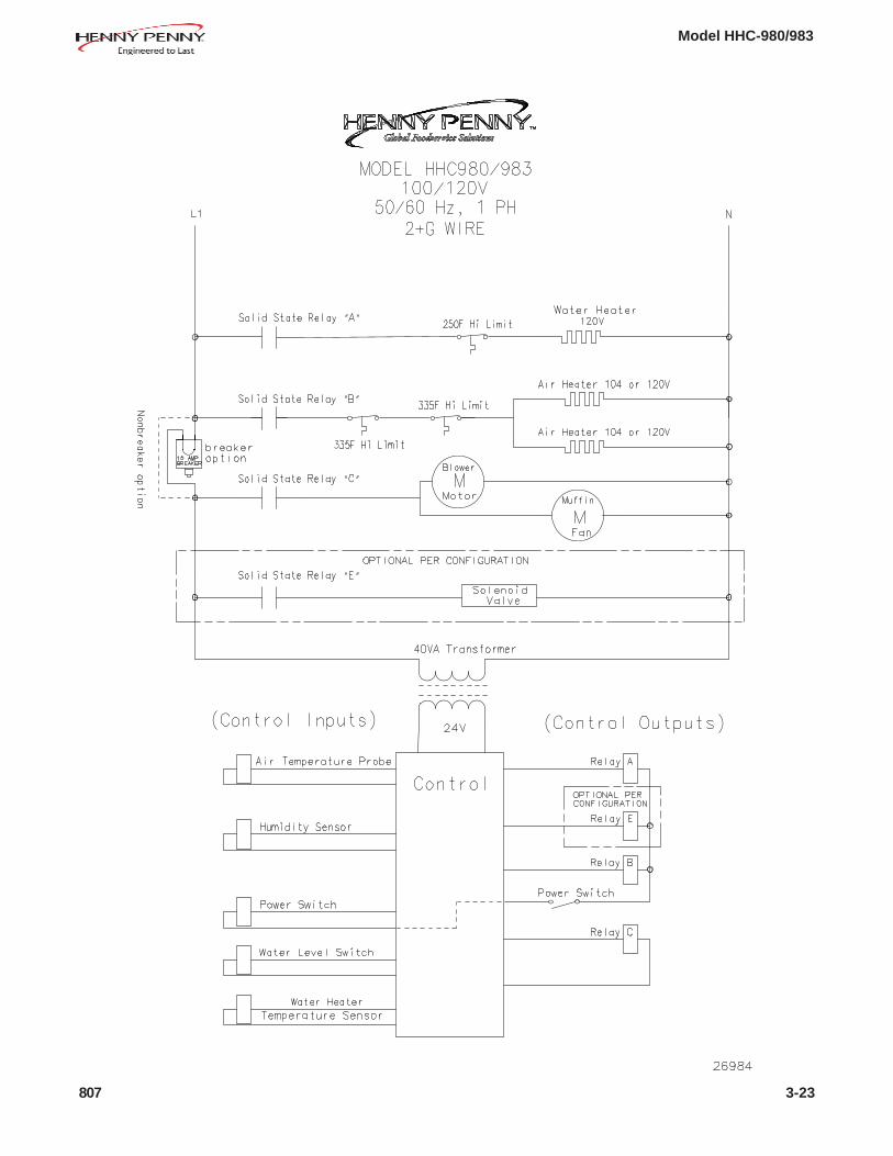
Model HHC-980/983
807 3-23

Model HHC-980/983
3-24 807
Model HHC-980/983
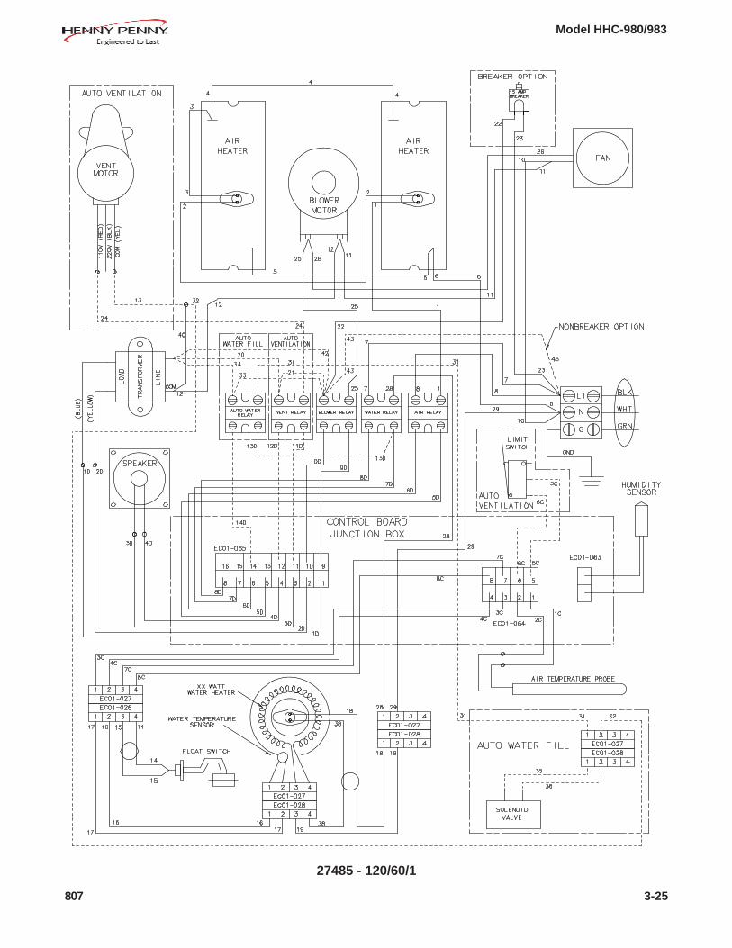
27485 - 120/60/1
807 3-25
Model HHC-980/983
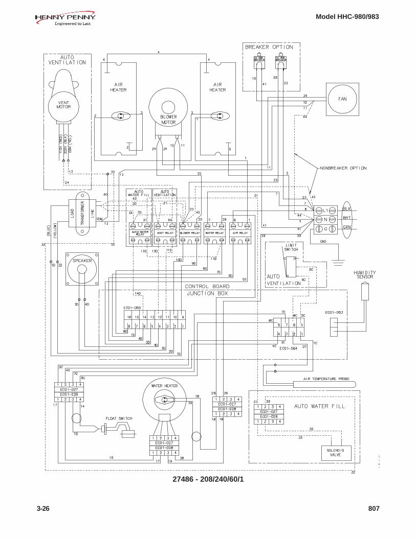
3-26 807
27486 - 208/240/60/1

Model HHC-980/983
27487 - 230/50/1
805 3-27

Model HHC-980/983
68491
3-28 805

Model HHC-980/983
This section lists the replaceable parts of the Henny PennyHHC-980/983 units.
Use only genuine Henny Penny parts in your cabinet. Usinga part of lesser quality or substitute design may result indamage to the unit, or personal injury.
Once the parts that you want to order have been found in theparts list, write down the following information:
Example: Item Number 4Part Number 16684Description Cooling Fan
From data plate, list the following information:
Example: Product Number HHC980.0Serial Number AW001IEVoltage 208 Volt
Your distributor has a price list and will be glad to informyou of the cost of your parts order.
Commonly replaced items are stocked by your localdistributor and will be sent out when your order is received.Other parts will be ordered, by your distributor, from HennyPenny Corporation.
All replacement parts (except lamps and fuses) are warrantedfor 90 days against manufacturing defects and workmanship.If damage occurs during shipping, notify the carrier at onceso that a claim may be properly filed. Refer to warranty inthe front of the manual for other rights and limitations.
Recommended replacement parts, stocked by your distributor, areindicated with √ √ √ √ √ in the parts lists. Please use care when orderingrecommended parts, because all voltages and variations aremarked. Distributors should order parts based upon commonvoltages and equipment sold in their territory.
206 4-1
SECTION 4. PARTS INFORMATION
4-1. INTRODUCTION
4-2. GENUINE PARTS
4-3. WHEN ORDERING PARTS
4-4. PRICES
4-5. DELIVERY
4-6. WARRANTY
4-7. RECOMMENDEDSPARE PARTS FORDISTRIBUTORS

Model HHC-980/983
QuantityItem No. Part No. Description 980 983
√√√√√ 1 63419 Speaker Assembly 1 1√√√√√ 2 63460 Transformer Assembly - 120V Pri. - 1√√√√√ 2 63459 Transformer Assembly - 208/240V Pri.-24V Sec. 1 1√√√√√ 3 40645 Relay - 25A - Solid State 4 4
4 63832 Terminal Block Assembly 1 1√√√√√ 5 16684 Cooling Fan Assy - 120V - 1√√√√√ 5 16688 Cooling Fan Assy - 220V 1 1√√√√√ 6 66879 Assy - Resistor Capacitor 1 1
1 2 3 4 5
4-2 707
6
√√√√√ recommended parts

Model HHC-980/983
7
3
4
5
6
QuantityItem No. Part No. Description 980 983
√√√√√ 1 14385 Kit - Control Board - 980 1 -√√√√√ 1 14386 Kit - Control Board - 983 - 1√√√√√ 2 63464 Power Switch 1 1
3 26858 Decal - Pizza Hut HHC-980 1 -3 26859 Decal - Pizza Hut HHC-983 - 14 32768 Assy - 980 Glass Door - RH Top 1 or 2 -4 32769 Assy - 980 Glass Door - RH Bottom 1 or 2 -4 32770 Assy - 980 Glass Door - LH Top 1 or 2 -4 32771 Assy - 980 Glass Door - LH Bottom 1 or 2 -4 32774 Assy - 983 Glass Door - RH - 1 or 24 32775 Assy - 983 Glass Door - LH - 1 or 25 14272 Kit - Door Handle 2 or 4 26 24844 Pizza Trays 10 57 14271 Kit - Door Hinge 4 or 8 48* 27149 Door Stops (RH-RH & LH-LH pass thru units) 4 -
√√√√√ recommended parts*not shown
1006 4-3
2
1

Model HHC-980/983
1 2 3 8 4 5
6
QuantityItem No. Part No. Description 980 983
√√√√√ 1 18364 Fuse Holder Assembly 2 1√√√√√ 1 EF02-007 Fuse - 15 Amp 2 1√√√√√ 1 EF02-006 Fuse Holder 2 1
2 26906 Power Cord Assembly - 120V-20A - 12 27312 Power Cord Assembly - 250V-20A 1 -2 63870 Power Cord Assembly - 120V-30A 1 12 63927 Power Cord Assembly - 120V-50A 1 -2 63930 Power Cord Assembly - 208/240V-20A 1 12 72532 Power Cord Assembly - 120-30A-Twist-Lock (Canada) - 1
√√√√√ 3 64285 Air Heater Assy-1000W-104V(208V units) (includes 63815 gasket) 2 -√√√√√ 3 64128 Air Heater Assy-1000W-120V (includes 63815 gasket) 2 -√√√√√ 3 64126 Air Heater Assy-600W-120V (includes 63815 gasket) - 2√√√√√ 4 63363 Blower - Motor 120V - 1√√√√√ 4 63362 Blower - Motor 208V 1 1√√√√√ 4 63361 Blower - Motor 240V 1 1
5 63814 Gasket - Plate - Motor Mounting 1 1√√√√√ 6 18201 Sensor - High Limit - 335 Deg. 2 2√√√√√ 6 59275 Sensor - High Limit - 375 Deg. - CE (manual reset) 2 2√√√√√ 7* 51068 Assy - EMC Filter Board 1 1
8 59496 Stud Assy- Motor Mounting Plate 1 19* 63360 Fan Blade 5 3/8" 1 1
√√√√√ recommended parts*not shown
4-4 1114

Model HHC-980/983
1 2
QuantityItem No. Part No. Description 980 983
√√√√√ 1 14390 Kit - Humidity Sensor (before 4/1/2005) 1 1√√√√√ 1 140135 Kit - Humidity Sensor (4/1/2005 & after) 1 1√√√√√ 2 64283 Probe-Air Temp 1 1√√√√√ 3* 14391 Kit - Calibration Board 1 1
512 4-5
√√√√√ recommended parts*not shown

Model HHC-980/983
QuantityItem No. Part No. Description 980 983
1 27155 Caster 2 21 27321 Caster - Dual 2 in. - Swivel (under counter models) - 42 FP01-127 1/2 x 1/2 90 Degree Street 1 12 FP01-167 Elbow - 90 Deg. 1/2 x 3/3 BR Street (countertop models) - 13 63389 Valve - Drain w/Handle 1 1
39169 Handle - Drain (983s w/casters) - 13 27359 Valve - Drain (countertop & under counter models) - 14 FP01-131 Male Connector - 5/8 Tube 1 14 FP01-159 Male Connector - 5/8 x 3/8 Tube (countertop models) - 1
√√√√√ 5 140170 Kit - Water Pan Heater - 120V - 1√√√√√ 5 140171 Kit - Water Pan Heater - 208V 1 1√√√√√ 5 140172 Kit - Water Pan Heater - 240V 1 1
6 71130 Spacer - Water Heater 1 17 68130 Insulator - Water Heater 1 18 67524 Plate - Water Heater Backing 1 19 NS02-007 Nut Hex Keps - #8-32 C 12 12
√√√√√ 10 63831 Hi Limit - Water Pan 1 1√√√√√ 10 64297 Hi Limit - Water Pan - CE (manual reset) 1 1
11 27154 Caster - Locking 2 212 64154 Check Valve 1 113 63463 Water Pan Hose 2 214 26968-001 Hose - Water - 980/983 - 13 in. 1 114 67186 Tube - Water Inlet (copper) - WRAS 1 115 26968-003 Hose - Water - 980 - 69 in. 1 -15 67229 Tube - Water Supply - 980 (copper-UK & Ireland) 1 -15 26968-002 Hose - Water - 983 - 39 in. - 115 67187 Tube - Water Supply - 983 (copper-UK & Ireland) - 116* 64351 Cover - Water Pan Heater 1 116* 21031 Cover - Water Pan Heater - CE 1 116* 27344 Cover - Water Pan Heater (under counter models) - 1
4-6 √√√√√ recommended parts/*not shown 414
13
1
2 3 4 6 7 8 9 5 10
11
12
14
15

Model HHC-980/983
1 2 3 4 5 6 7 8 9
QuantityItem No. Part No. Description 980 983
1 FP01-152 Fitting -3/8 Hose Barb -1/8 NPT 1 1√√√√√ 2 25147 Solenoid - 120V - 1√√√√√ 2 27343 Solenoid - 208V 1 1√√√√√ 2 25409 Solenoid - 240V 1 1√√√√√ 2 32646 Solenoid - WRAS - 220/240V 1 1
3 FP01-012 Nipple Reducing 1/4 to 1/8 Z 1 1√√√√√ 4 25208 Water Strainer 1 1
5 FP01-053 Fitting 3/8 ID Tubing -1/4 NPT 1 16 FP01-156 Fitting-1/4 Hose Barb-1/8 NPT 1 17 FP01-154 Socket-Quick Connect 1/8 IN 1 18 FP01-155 Plug-Quick Connect 1/8 IN 1 19 FP01-157 Elbow-Male 1/4 NPT X 1/8 NPT - 90 1 1
√√√√√ recommended parts
206 4-7

Model HHC-980/983
QuantityItem No. Part No. Description 980 983
√√√√√ 1 25643 Gasket - Door - 980 2 or 4 -√√√√√ 1 25793 Gasket - Door - 983 - 2
2 24909 Assy. - 983 Air Duct - 22 27384 Assy. - 980 Air Duct - Upper 2 -2 32511 Assy. - 980 Air Duct - Lower 2 -
√√√√√ 3 140245 Kit-Switch - Float Assembly 1 14 63525 Assy-Water Pan Cover & Ring (concentration ring) 1 14 27305 Assy-Water Pan Cover & Ring-under counter model - 1
(concentration ring)4 SC01-076 Screw - #8-32 x 1/4 PH THD S 8 84 ME50-048 Standoff - .25 dia. x .63 lg. #8-32 SS 4 4
√√√√√ recommended parts
1 2 3 4 2
4-8 1012
Model HHC-980/983
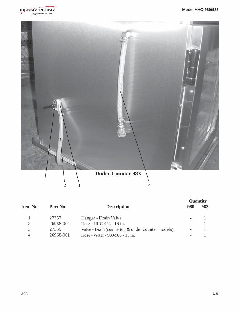
QuantityItem No. Part No. Description 980 983
1 27357 Hanger - Drain Valve - 12 26968-004 Hose - HHC-983 - 16 in. - 13 27359 Valve - Drain (countertop & under counter models) - 14 26968-001 Hose - Water - 980/983 - 13 in. - 1
1 2 3 4
Under Counter 983
303 4-9