Embed Size (px)
Citation preview
95 BIF / BAF
Filter Manual
Inst
alla
tion a
nd
Opera
tion M
anual
REVISION # 1
REVISION DATE 8/15/2014
80150348
1. Read all instructions carefully before operation. 2. Avoid pinched o-rings during installation by applying (provided with install kit) NSF certified lubri-
cant to all seals. 3. This system is not intended for treating water that is microbiologically unsafe or of unknown
quality without adequate disinfection before or after the system.
NOTE:
1.5” RISER / DISTRIBUTOR PIPE SHOULD BE CUT 1/2” BELOW
THE TOP SURFACE OF THE TANK INSERT.

2
Safety Guide
For your safety, the information in this manual must be followed to minimize the risk of electric shock, property damage or personal injury.
Unpacking / Inspection
PAGE
Safety Guide 2
Proper Installation 3
Unpacking / Inspection 3
Specification 4
Before Starting Installation 5
Sizing Requirements 6
Filter Media Loading Instructions 7
Installation Instructions 8
Start Up Instructions 9
Programming 9
About The System 18
Maintenance 19
Powerhead Assembly 22
Control Valve Body Assembly 23
Trouble Shooting 26
Warranty 27
Table of Contents
Check and comply with your provincial / state and local codes. You must follow these guidelines.
Use care when handling the filter tank. Do not turn upside down, drop, drag or set on sharp protrusions.
The filter system works on 12 volt-60 Hz electrical power only. Be sure to use only
the included transformer. Transformer must be plugged into an in-
door 120 volt, grounded outlet only.
WARNING: This system is not intend-
ed for treating water that is microbiologi-cally unsafe or of unknown quality without adequate disinfection before or after the system.
Be sure to check the entire unit for any shipping damage or parts loss. Also note damage to the shipping cartons. Contact the transportation company for all damage and loss claims. The manufacturer is not responsible for damages in transit. Small parts, needed to install the filter, are in a parts bag. To avoid loss of the small parts, keep them in the parts bag until you are ready to use them.

3
Proper Installation
Install or store where it will not be ex-posed to temperatures below freezing or exposed to any type of weather. Water freezing in the system will break it. Do not attempt to treat water over 100°F.
Do not install in direct sunlight. Excessive sun or heat may cause distortion or other damage to non-metallic parts.
Properly ground to conform with all gov-erning codes and ordinances.
Use only lead-free solder and flux for all sweat-solder connections, as required by state and federal codes.
Maximum allowable inlet water pressure is 125 psi. If daytime pressure is over 80 psi, night time pressure may exceed the maximum. Use a pressure reducing valve to reduce the flow if necessary.
WARNING: Discard all unused parts and packaging material after installation. Small parts remaining after the installation could be a choke hazard.
This water filter system must be properly installed and located in accordance with the Installation Instructions before it is used.
AIR TANK MEDIA TANK
3/4” OR 1” CHECK
VALVE (INLET)
3/8” CHECK VALVE
(BRINE LINE)

4
Specifications
Continuous operation at flow rates greater than the service flow rate may affect capacity and efficiency performance.
The manufacturer reserves the right to make product improvements which may deviate from the specifications and
descriptions stated herein, without obligation to change previously manufactured products or to note the change.
95BAF-100 95BAF-150 95BAF-200 95BAF-300 95BAF-400 95BAF-500
15054054 15054055 15054042 15054043 15054044 15054045
Typical Service Flow Rate 3.0 gpm 4.0 gpm 5.0 gpm 6.0 gpm 7.0 gpm 9.0 gpm
Peak Flow Rate 6.0 gpm 10.0 gpm 12.0 gpm 14.0 gpm 16.0 gpm 18.0 gpm
Backwash Flow Rate 5.0 gpm 5.0 gpm 7.0 gpm 10.0 gpm 14.0 gpm 21.0 gpm
Filter Media Volume - Cubic Feet 1.0 ft3 1.5 ft3 2.0ft3 3.0 ft3 4.0 ft3 5.0 ft3
Filter Tank Size 10x44 10x54 12x52 14x65 16x65 18x65
Air Contact Tank Size 8x44 10x54 12x52 14x65 14x65 14x65
Shipping Weight 150 lbs 188 lbs 248 lbs 368 lbs 443 lbs 518 lbs
Media Loaded Yes Yes No No No No
Maximum Iron
Hydrogen Sulfide
Mangansese
Iron Bacteria Removal
pH
Plumbing Connections
Electrical Requirements
Water Temperature
Water Pressure
95BIF-100 95BIF-150 95BIF-200 95BIF-300 95BIF-400 95BIF-500
15054056 15054057 15054046 15054047 15054048 15054049
Typical Service Flow Rate 3.0 gpm 4.0 gpm 5.0 gpm 6.0 gpm 7.0 gpm 9.0 gpm
Peak Flow Rate 6.0 gpm 10.0 gpm 12.0 gpm 14.0 gpm 16.0 gpm 18.0 gpm
Backwash Flow Rate 5.0 gpm 5.0 gpm 7.0 gpm 10.0 gpm 14.0 gpm 21.0 gpm
Filter Media Volume - Cubic Feet 1.0 ft3 1.5 ft3 2.0ft3 3.0 ft3 4.0 ft3 5.0 ft3
Filter Tank Size 10x44 10x54 12x52 14x65 16x65 18x65
Air Contact Tank Size 8x44 10x54 12x52 14x65 14x65 14x65
Shipping Weight 150 lbs 188 lbs 248 lbs 368 lbs 443 lbs 518 lbs
Media Loaded Yes Yes No No No No
Maximum Iron
Hydrogen Sulfide
Mangansese
Iron Bacteria Removal
pH
Plumbing Connections
Electrical Requirements
Water Temperature
Water Pressure
95BIFMN-100 95BIFMN-150 95BIFMN-200 95BIFMN-300 95BIFMN-400 95BIFMN-500
15054058 15054059 15054050 15054051 15054052 15054053
Typical Service Flow Rate 3.0 gpm 4.0 gpm 5.0 gpm 6.0 gpm 7.0 gpm 9.0 gpm
Peak Flow Rate 6.0 gpm 10.0 gpm 12.0 gpm 14.0 gpm 16.0 gpm 18.0 gpm
Backwash Flow Rate 5.0 gpm 5.0 gpm 7.0 gpm 10.0 gpm 14.0 gpm 21.0 gpm
Filter Media Volume - Cubic Feet 1.0 ft3 1.5 ft3 2.0ft3 3.0 ft3 4.0 ft3 5.0 ft3
Filter Tank Size 10x44 10x54 12x52 14x65 16x65 18x65
Air Contact Tank Size 8x44 10x54 12x52 14x65 14x65 14x65
Shipping Weight 150 lbs 188 lbs 248 lbs 368 lbs 368 lbs 368 lbs
Media Loaded Yes Yes No No No No
Maximum Iron
Hydrogen Sulfide
Mangansese
Iron Bacteria Removal
pH
Plumbing Connections
Electrical Requirements
Water Temperature
Water Pressure
Min. 20 - Max. 125 psi
30.0 ppm
5.0 ppm
Min 39 - Max. 100 degrees Fahrenheit
Min. 20 - Max. 125 psi
Input 120V 60 Hz - Output 12V 650mA
5.0 ppm
1.0 ppm
3/4", 1", 1-1/4", 1-1/2"
Min 39 - Max. 100 degrees Fahrenheit
Min. 20 - Max. 125 psi
0.0 ppm
No
"
3/4", 1", 1-1/4", 1-1/2"
Input 120V 60 Hz - Output 12V 650mA
Specifications
Specifications
Specifications
Yes
6.0 - 6.9
30.0 ppm
30.0 ppm
5.0 ppm
0.0 ppm
Yes
7.0 - 8.5
3/4", 1", 1-1/4", 1-1/2"
Input 120V 60 Hz - Output 12V 650mA
Min 39 - Max. 100 degrees Fahrenheit

5
Before Starting Installation
Place the filter tank as close as possible to the pressure tank (well system) or water meter (city water).
Place the filter tank as close as possible to a floor drain, or other acceptable drain point (laundry tub, sump, standpipe, etc.).
Connect the filter to the main water supply pipe BEFORE the water heater. DO NOT RUN HOT WATER THROUGH THE FIL-TER. Temperature of water passing through the filter must be less than 100 deg. F.
Do not install the filter in a place where it could freeze. Damage caused by freez-ing is not covered by the warranty.
Put the filter in a place water damage is least likely to occur if a leak develops. The manufacturer will not repair or pay for wa-ter damage.
A 120 volt electric outlet, to plug the in-cluded transformer into, is needed within 6 feet of the filter. The transformer has an attached 6 foot power cable. Be sure the electric outlet and transformer are in an inside location, to protect from wet weather.
If installing in an outside location, you must take the steps necessary to assure the filter, installation plumbing, wiring, etc., are as well protected from the ele-ments, contamination, vandalism, etc., as when installed indoors.
Keep the filter out of direct sunlight. The sun’s heat may soften and distort plastic parts.
Where To Install The Filter
Tools, Pipe, and Fittings, Other Materials
Pliers Screwdriver Teflon tape Razor knife Two adjustable wrenches Additional tools may be required if modifi-
cation to home plumbing is required. Plastic inlet and outlet fittings are included
with the filter. To maintain full valve flow, 3/4” or 1” pipes to and from the filter fit-tings are recommended. You should main-tain the same, or larger, pipe size as the water supply pipe, up to the filter inlet and
outlet. Use copper, brass, or PEX pipe and fittings. Some codes may also allow PVC plastic
pipe. ALWAYS install a 3 way shut-off valves by-
pass. These valves let you turn off water to the filter for repairs if needed, but still have water in the house pipes.
3/4” Pipe (1.05” OD) drain line is needed for the valve drain.

6
Sizing Requirements
Water Pressure
The water system must have a pump big enough to deliver the recommended backwash rate with a minimum pressure at the inlet of the filter of 30 psi. If the existing system can-not do this, it must be upgraded to do so. Whenever possible, the water system should be adjusted to deliver at least 30 psi for even more satisfactory results.
Backwash Flow Rates
Check Your Pumping Rate
Two water system conditions must be checked carefully to avoid unsatisfactory operation or equipment damage: 1. Minimum water pressure required at the filter tank inlet is 30 psi. 2. Measuring the pumping rate of your pump: With the pressure tank full, draw water into a container of known volume, and measure the number of gallons drawn until the pump starts again. This is draw-down. Divide this figure by cycle time and multiply the result by 60 to arrive at the pumping rate in gallons per mi-nute (gpm). To aid in your calculation, insert the date in the following formula: DRAW-DOWN ______ ÷ CYCLE TIME _______ x 60 = PUMPING RATE ________ (gals) (secs.) (Gpm) EXAMPLE: CYCLE TIME is 53 seconds. DRAW-DOWN is 6 gallons; then, PUMPING RATE equals: 6 gallons ÷ 53 seconds x 60 = 6.8 gpm See chart on page 4 for minimum flow rates. NOTE: If your pumping rate is inadequate for the model, do not install your filter until the problem has been corrected.
The most important criteria in sizing a filter is the capacity of the pump. The water must pass through the filter media at the proper service flow rate. The filter must also be back-washed at a flow rate sufficient to dislodge and remove the captured particles. Failure to provide sufficient water will cause a build-up of particles in the filter media, impairing its ability. In order for your filter to backwash and rinse properly, your pump must be capable of providing the backwash flow rates indicated on page 4.

7
MODEL 200 TOP OF TANK
BOTTOM OF TANK
1
2
# MEDIA BIF 200 BIF 300
3 MIXED MEDIA 2 BAGS 3 BAGS
2 FINE GRAVEL 1/8"X1/16" 8 LBS 20 LBS
1 COARSE GRAVEL 1/2" X 1/4" 8 LBS 15 LBS
Filter Media Loading Instructions
4
2 3
Model Media 95xxx-200 95xxx-300 95xxx-400 95xxx-500
4 Filter Media 2 Bags 3 bags 4 bags 5 bags
3 Fine Gravel 1/8"x1/16" 12 lbs 25 lbs 30 lbs 40 lbs
2 Medium 1/8"x1/4" 25 lbs 30 lbs 40 lbs
1 Coarse Gravel 1/2"x1/4" 12 lbs 25 lbs 30 lbs 40 lbs
8
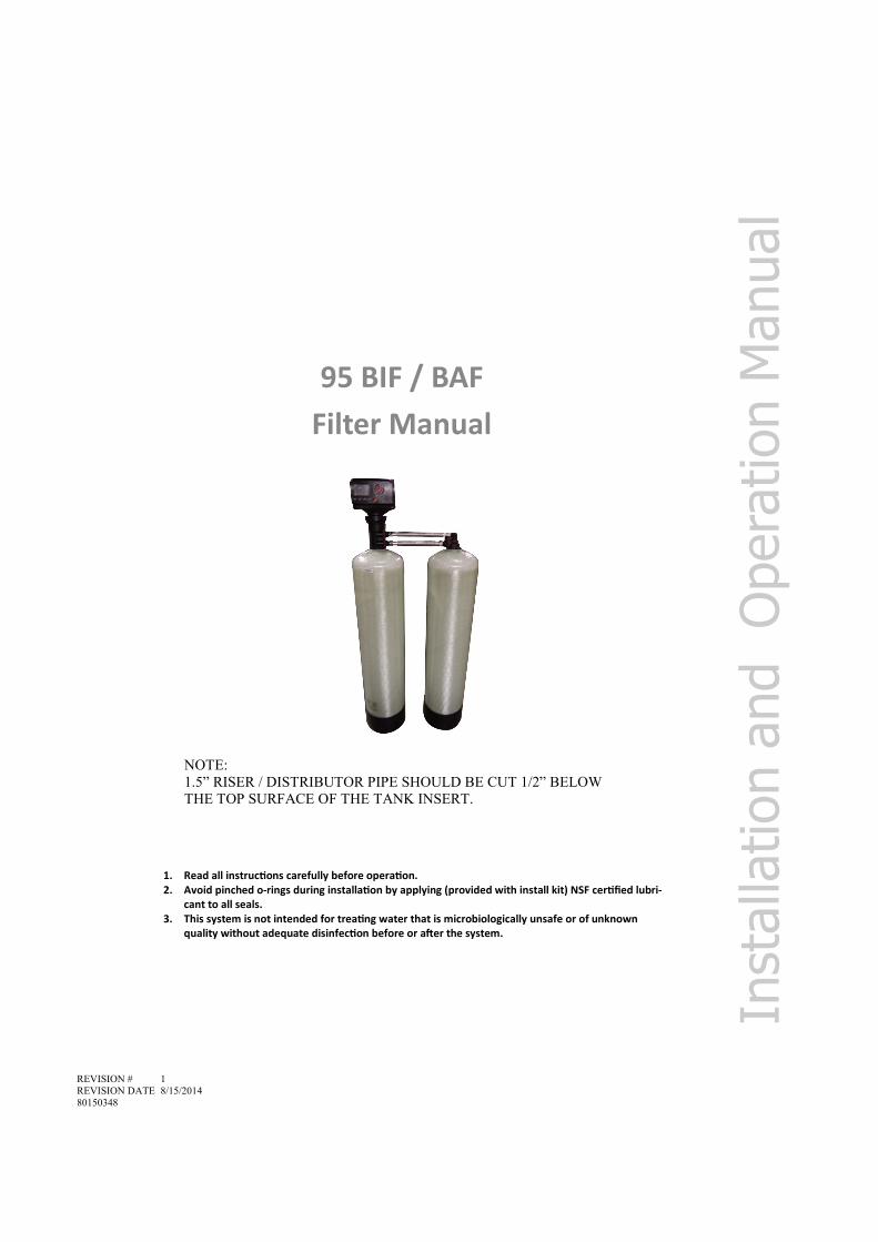
Installation Instructions
1. Locate the Air and Media Tank close to a drain where the system will be installed. The surface should be clean and level.
2. Shut off all water at main supply. On a private well system, turn off power to pump and drain pressure tank. Make certain pressure is relieved from complete system by opening nearest faucet to drain the system. Shut off fuel supply to water heater.
3. Cut the main supply line as required to fit plumbing to the control valve being sure to add a three valve bypass.
4. Solder or solvent weld plumbing. Do not apply heat to any fitting connected to the control valve as damage may result to the internal parts. Check to be certain water supply pipe is connected to the con-trol valve inlet fitting and pipe connected to control valve outlet fitting is in direction of house service.
5. Perform all plumbing according to local plumbing codes. 6. Use a ½” minimum pipe or tubing size for the drain line. 7. Use a ¾” pipe or tubing for backwash flow rates that exceed 7 gpm or length that exceeds 20ft (6 m).
NOTE: ON COPPER PLUMBING SYSTEMS BE SURE TO INSTALL A GROUNDING WIRE BETWEEN THE INLET AND OUTLET PIPING TO MAINTAIN GROUNDING.
8. Any solder joints near the valve must be done before connecting any piping to the valve. Always leave at least 6" (152 mm) between the valve and joints when soldering pipes that are connected to the valve. Failure to do this could cause damage to the valve.
9. Install ¾” or 1” check valve on inlet of control valve. 10. Connect the drain line to the valve. Only use Teflon tape on the drain fitting. 11. Place unit in the bypass position. 12. Slowly turn on the main water supply. 13. At the nearest cold treated water tap nearby remove the faucet screen, open the faucet and let water
run a few minutes or until the system is free of any air or foreign material resulting from the plumbing work. Close the water tap when water runs clean.
AIR TANK MEDIA TANK
3/4” OR 1” CHECK VALVE (INLET)
3/8” CHECK VALVE (BRINE LINE)

9
System Start-Up
Programming Instructions
Key Pad Configuration
MENU Enter or exit the system menu. Press and hold the button for 3 seconds to un-lock the screen.
SET/REGEN Press this button to select a program or to save the settings. Press and hold the button for 3 seconds to initiate a manual regeneration.
DOWN / UP Press these buttons to increase or decrease the value of the settings. Press the buttons to enter the previous or the next menu.
Start-up Instructions
1. Plug the valve into an approved power source. 2. When power is supplied to the control, the screen will display “Advancing to Service Wait
Please” while it finds the service position. 3. If screen is locked, press MENU for 3 seconds to unlock. Press and hold the SET / REGEN
button for 3 seconds to enter the manual regeneration screen. An option for delayed or immediate regeneration will appear. Press SET REGEN, then press the DOWN button to select IMMEDIATE. Press the MENU button to save setting and immediately start moving to the BACKWASH position. Once in BACKWASH, unplug the power cord.
4. Open the inlet on the bypass valve slowly and allow water to enter the unit. Allow all air to escape from the unit before turning the water on fully then allow water to run to drain for 30 minutes (this is extremely important on BIF/BIFMN models to prevent cementing of the bed). Plug in the power cord.
5. Press any button to advance to the BRINE (AIR DRAW) position. Check the drain line flow.
6. The valve will automatically advance to the SERVICE position after the BRINE (AIR DRAW) cycle is complete. Open the outlet valve on the bypass, then open the nearest treated water faucet and allow the water to run until clear, close the tap and replace the faucet screen.
7. Program time, date, and number of days between regenerations into controller using Pro-gramming Instructions
10
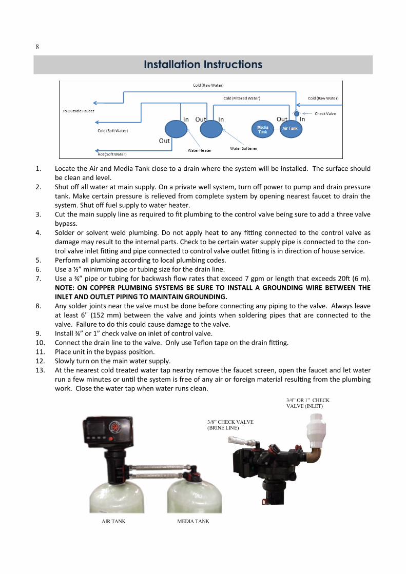
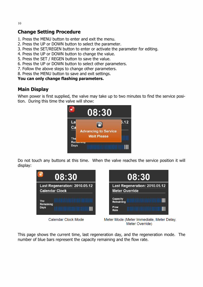
Main Display
When power is first supplied, the valve may take up to two minutes to find the service posi-tion. During this time the valve will show: Do not touch any buttons at this time. When the valve reaches the service position it will display: This page shows the current time, last regeneration day, and the regeneration mode. The number of blue bars represent the capacity remaining and the flow rate.
Change Setting Procedure
1. Press the MENU button to enter and exit the menu. 2. Press the UP or DOWN button to select the parameter. 3. Press the SET/REGEN button to enter or activate the parameter for editing. 4. Press the UP or DOWN button to change the value. 5. Press the SET / REGEN button to save the value. 6. Press the UP or DOWN button to select other parameters. 7. Follow the above steps to change other parameters. 8. Press the MENU button to save and exit settings. You can only change flashing parameters.

11
The screen will be locked after 3 minutes. To unlock the screen press and hold the MENU key for 3 seconds.
MANUAL REGENERATION
Press and hold the SET REGEN button for 3 seconds to enter the manual regeneration page. The screen will display: 1. Press the UP or DOWN button to choose option. 2. If you choose DELAY, the valve will start a regeneration at the next regeneration time (default is 2:00 AM). 3. If you choose IMMEDIATE, the valve will start a regeneration immediately. When a regeneration is started, the screen will display:
12
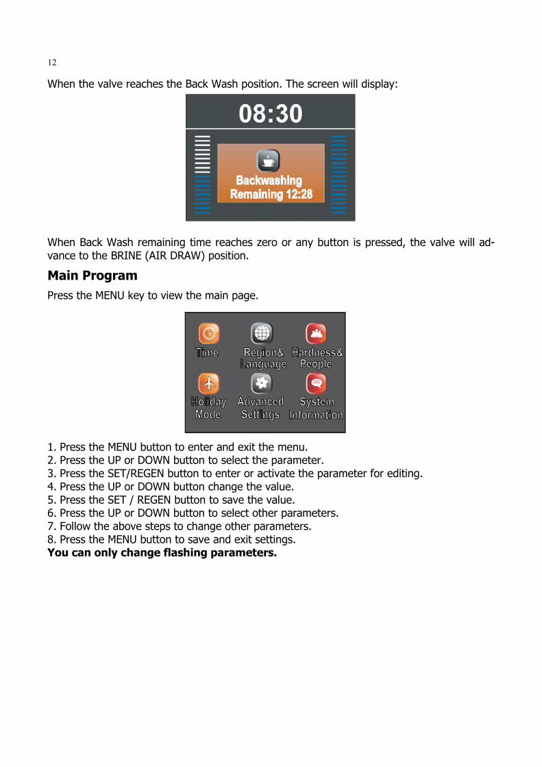
When the valve reaches the Back Wash position. The screen will display: When Back Wash remaining time reaches zero or any button is pressed, the valve will ad-vance to the BRINE (AIR DRAW) position.
Main Program
Press the MENU key to view the main page.
1. Press the MENU button to enter and exit the menu. 2. Press the UP or DOWN button to select the parameter. 3. Press the SET/REGEN button to enter or activate the parameter for editing. 4. Press the UP or DOWN button change the value. 5. Press the SET / REGEN button to save the value. 6. Press the UP or DOWN button to select other parameters. 7. Follow the above steps to change other parameters. 8. Press the MENU button to save and exit settings. You can only change flashing parameters.

13
Choose Time icon to adjust the current date and time.
Choose Region icon to change the display unit of measures. Choose Language icon to change the display language. Note English may be only option depending on version of software.
Choose Holiday Mode icon to activate it. The system will perform a brief back wash and rinse every 7 days. When turning Holiday Mode ON, remember to add the end date. This will insure the valve will return to normal operation on that date.

14
Advance settings has two options. Press SET REGEN button for 3-5 seconds to enter menu. Choose Manual Settings to manually adjust settings.
In Regen Mode you can select four different regeneration modes.
Calendar Clock: the unit will initiate regeneration at the next pre-set regeneration time based on the interval of days between regeneration days. Meter Immediate: the unit will initiate regeneration immediately after the volume remain-ing reaches zero. Meter Delayed: this is the most common setting. When the volume remaining reaches ze-ro, the system will initiate regeneration at the next preset regeneration time. Meter Override: when the volume remaining reaches zero, the system will initiate regen-eration at the next pre-set regeneration time. If the days between regeneration are reached before the volume remaining reaches zero, the system will override the meter setting and initiate regeneration.
15
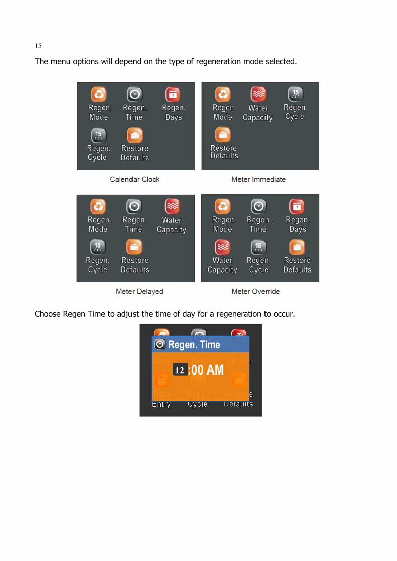
The menu options will depend on the type of regeneration mode selected.
Choose Regen Time to adjust the time of day for a regeneration to occur.
12

16
Restore Defaults will erase all the current settings. Be careful when choosing this since you will lose all the current settings and the default settings loaded back in may not be the cor-rect settings for your system.
Choose Regen. Cycle to adjust the length of time for each cycle. Note that filter valve mode only has two cycles: Backwash and Rinse.
Choose Regen. Days to adjust the interval (days) between regenerations.
17
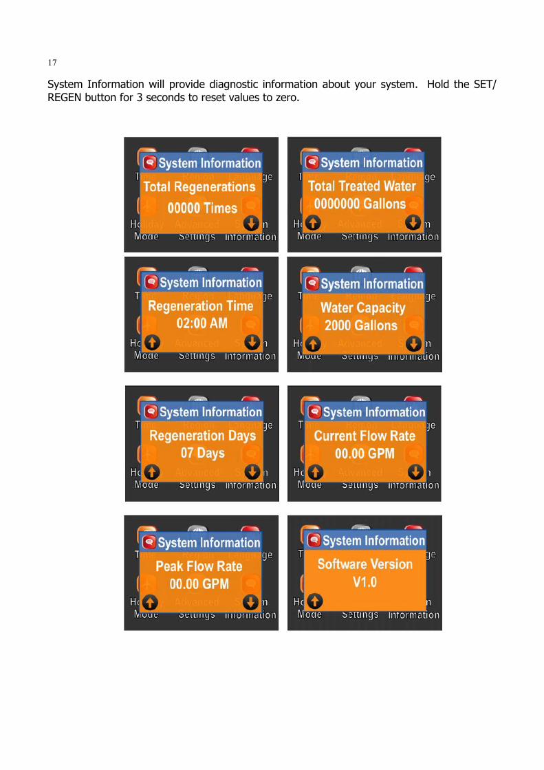
System Information will provide diagnostic information about your system. Hold the SET/REGEN button for 3 seconds to reset values to zero.

18
Automatic Raw Water Bypass During Regeneration
New Sounds
You may notice new sounds as your filter operates. The regeneration cycle lasts up to 90 minutes. During this time, you may hear water running intermittently to the drain.
Control Operation During A Power Failure
In the event of a power failure, the valve will keep track of the time and day for 48 hours. The programmed settings are stored in a non-volatile memory and will not be lost during a power failure. If power fails while the unit is in regeneration, the valve will finish regenera-tion from the point it is at once power is restored. If the valve misses a scheduled regener-ation due to a power failure, it will queue a regeneration at the next regeneration time once power is restored.
About The System
Regeneration Process
The regeneration cycle can last 90 minutes after which filtered water service will be re-stored. During regeneration, un-filtered water is automatically bypassed for use in the household. Hot water should be used as little as possible during this time to prevent un-filtered water from filling the water heater. This is why automatic regeneration is set for sometime during the night and manual regenerations should be performed when little or no water will be used in the household. Normal regeneration time is 12:00 AM.
Periodically the filter will require a back wash to clean the trapped particles and unpack the filter bed to restore the system flow rates. The table below explains the regeneration steps.
Step Name Description
#1 Back Wash
Fresh water is introduced to the bottom of the tank flowing upwards expanding
the filter media to rinse out any dirt or small particles to the drain and to un-
compact the bed to restore full service flow rates.
#2 Air-Draw Air is drawn into the system and fills the first and second tank.

19
Maintenance
To retain the attractive appearance of your new water filter, clean occasionally with mild soap solution. Do not use abrasive cleaners, ammonia or solvents. Never subject your filter to freezing or to temperatures above 100°F.
Care of Your System
Maintenance of your new water filter requires very little time or effort but it is essential. Regular maintenance will ensure many years of efficient and trouble-free operation. 1. Periodically make sure your pump is performing satisfactorily to ensure sufficient water is
available for backwashing the filter. 2. Periodically test your raw and filtered water to ensure conditions are still the same for
your original settings and that the unit is working they way it is intended to. Water test-ing is often the best way to determine when the filter media will require replacement.
3. Periodically check that the drain line is clear and free from any obstructions.
Model
CYCLE TIME (MINUTES)
BACKWASH BRINE (AIR
DRAW) RINSE REFILL
95xxx-100 15 45 0 0
95xxx-150 15 45 0 0
95xxx-200 15 45 0 0
95xxx-300 15 60 0 0
95xxx-400 15 60 0 0
95xxx-500 15 60 0 0

20
Removing Power Head Assembly
Manually remove the Power Head Assembly: Press and hold Manual Button With 8 hex key, insert Cam Hole, turn the Cam anti-clockwise to the marked position Remove the Connector Remove the Locking Bar Pull the Power Head Assembly outwards. Automatic remove the Power Head Assembly: Unlock the screen Press and hold Down button, the valve will advance the Cam to the marked position Remove the Connector Remove the Locking Bar Pull the Power Head Assembly outwards.
21
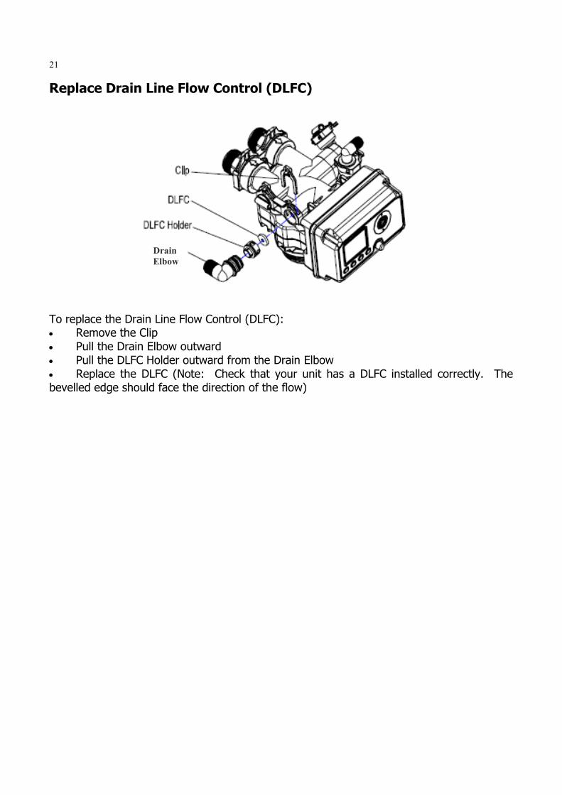
Replace Drain Line Flow Control (DLFC)
To replace the Drain Line Flow Control (DLFC): Remove the Clip Pull the Drain Elbow outward Pull the DLFC Holder outward from the Drain Elbow Replace the DLFC (Note: Check that your unit has a DLFC installed correctly. The bevelled edge should face the direction of the flow)
Drain
Elbow

22
Power Head Exploded View
Item No. Part No. Part Description Quantity
A01 05040038 Bnt95 Cable Jaket(without hole) 2
A02 26010028 O-Ring-Ø28×2.65 1
A03 05040086 O-Ring-Ø8×2 2
A04 05040005 Bnt95 Housing 1
A05 05040008 Bnt95 Driving Cam 1
A06 05040032 O-Ring-Ø4×1.5 1
A07 05040009 Bnt95 Driven Cam 1
A08 05010078 Magnet-Ø4x3 1
A09 05040095 Bnt95 Brine Valve Connector 1
A10 05056085 Screw-ST2.9×9.5(Large Wafer) 7
A11 05040052 Bnt95 Sensor Pcb 1
A12 05010047 Friction Point 6
A13 05040007 Bnt95 Mounting Plate 1
A14 05056084 Screw-ST3.5×13 10
A15 05056129 O-Ring-Ø23×3 1
A16 05040054 Bnt95 Meter Cable 1
05040039 Bnt95 Meter Cover 1
05040037 Bnt95 Cable Jaket(with hole) 1
05040086 O-Ring-Ø8×2 1
A17 05040053 Bnt95 Power Cable 1
05040037 Bnt95 Cable Jaket(with hole) 1
05040086 O-Ring-Ø8×2 1
A18 05040087 O-Ring-Ø5.5×1.5 4
A19 05040044 Bnt95 Motor Pin 1

23
Control Valve Exploded View
Item No. Part No. Part Description Quantity
A20 05040047 Bnt95 Motor (AC12V,2RPM) 1
A21 05040046 Bnt95 Gear Spring 1
A22 05040040 Bnt95 Gear 1
A23 05040033 Bnt95 Piston Rod Bush 1
A24 05040041 Bnt95 Manual Button 1
A25 05040085 O-Ring-Ø10×2.5 1
A26 05040051 Bnt95 Main PCB 1
A27 05056529 Bnt465 Button 4
A28 05040043 Bnt95 Housing Seal 1
A29 05040036 Bnt95 Clear Cover 1
A30 05040006 Bnt95 Cover 1
A31 05040092 Bnt95 Label (Filter) 1
05040093 Bnt95 Label (Softener) 1
A32 05040026 Bnt95 Brine Valve Piston Rod 1
24
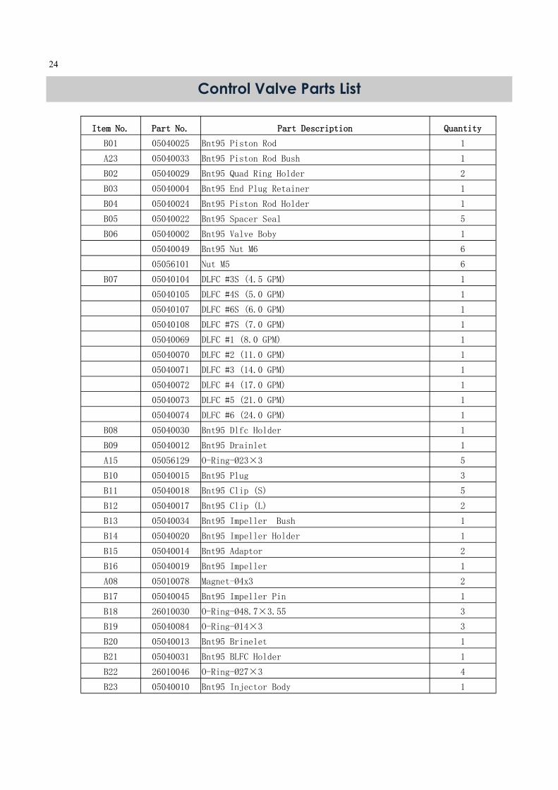
Control Valve Parts List
Item No. Part No. Part Description Quantity
B01 05040025 Bnt95 Piston Rod 1
A23 05040033 Bnt95 Piston Rod Bush 1
B02 05040029 Bnt95 Quad Ring Holder 2
B03 05040004 Bnt95 End Plug Retainer 1
B04 05040024 Bnt95 Piston Rod Holder 1
B05 05040022 Bnt95 Spacer Seal 5
B06 05040002 Bnt95 Valve Boby 1
05040049 Bnt95 Nut M6 6
05056101 Nut M5 6
B07 05040104 DLFC #3S (4.5 GPM) 1
05040105 DLFC #4S (5.0 GPM) 1
05040107 DLFC #6S (6.0 GPM) 1
05040108 DLFC #7S (7.0 GPM) 1
05040069 DLFC #1 (8.0 GPM) 1
05040070 DLFC #2 (11.0 GPM) 1
05040071 DLFC #3 (14.0 GPM) 1
05040072 DLFC #4 (17.0 GPM) 1
05040073 DLFC #5 (21.0 GPM) 1
05040074 DLFC #6 (24.0 GPM) 1
B08 05040030 Bnt95 Dlfc Holder 1
B09 05040012 Bnt95 Drainlet 1
A15 05056129 O-Ring-Ø23×3 5
B10 05040015 Bnt95 Plug 3
B11 05040018 Bnt95 Clip (S) 5
B12 05040017 Bnt95 Clip (L) 2
B13 05040034 Bnt95 Impeller Bush 1
B14 05040020 Bnt95 Impeller Holder 1
B15 05040014 Bnt95 Adaptor 2
B16 05040019 Bnt95 Impeller 1
A08 05010078 Magnet-Ø4x3 2
B17 05040045 Bnt95 Impeller Pin 1
B18 26010030 O-Ring-Ø48.7×3.55 3
B19 05040084 O-Ring-Ø14×3 3
B20 05040013 Bnt95 Brinelet 1
B21 05040031 Bnt95 BLFC Holder 1
B22 26010046 O-Ring-Ø27×3 4
B23 05040010 Bnt95 Injector Body 1

25
Item No. Part No. Part Description Quantity
B24 05040112 Bnt95 Nozzle-4S 1
05040113 Bnt95 Nozzle-5S 1
05040059 Bnt95 Nozzle-3 1
05040061 Bnt95 Nozzle-4 1
05040063 Bnt95 Nozzle-5 1
05040065 Bnt95 Nozzle-6 1
B35 05040117 Bnt95 Throat-4S 1
05040118 Bnt95 Throat-5S 1
05040060 Bnt95 Throat-3 1
05040062 Bnt95 Throat-4 1
05040064 Bnt95 Throat-5 1
05040066 Bnt95 Throat-6 1
B25 05040099 Screw-M5×55 (Hexagon with Washer) 2
B26 05040011 Bnt95 Injector Cover 1
B27 05040048 Bnt95 Brine Valve Screen 1
B28 05040027 Bnt95 Brine Valve Spacer 1
B29 05040028 Bnt95 Brine Valve Seal Cover 1
B30 05040050 Bnt95 Brine Valve Rod Pin 1
B31 05056070 Quad Ring 2
B32 05040023 Bnt95 Brine Valve Piston 1
B33 05040042 Bnt95 Brine Valve Seal 2
B34 05040081 Bnt95 BLFC-6 (0.9 GPM) 1
05040083 Bnt95 BLFC-7 (1.35 GPM) 1
B36 05040035 Bnt95 Air Disperser 1
B37 07060007 Valve Bottom Connector 1
B38 05056063 O-Ring-Ø78.74×5.33 1
B39 26010103 O-Ring-Ø25×3.55 1
B40 05040001 Bnt95 Valveset (2.5inch) 1
B41 05040094 O-Ring-Ø108×5.3 1
B42 05040091 Bnt95 Seal Holder 1
B43 05040088 Screw-M6×30 (Hexagon with Washer) 6
B44 05040090 Bnt95 Valveset (4inch) 1
B45 05040082 O-Ring-Ø47×3 2
B46 05040003 Bnt95 Spacer 10
B47 05040021 Bnt95 Piston 1
B48 05040016 Bnt95 Housing Locking Bar 2
B49 05056088 Screw-M5×16 (Hexagon with Washer) 4

26
Trouble Shooting Issue Possible Cause Possible Solution
A. Water clear when
drawn; turns red upon
standing (stain produc-
ing)
1. Insufficient air in air tank. a) Increase Brine Time (air draw)
b) Check valve not working.
2. Bypass open or leaking Close bypass and/or repair as necessary.
3. Filter bed overloaded with precipitated
iron due to insufficient backwash
Increase backwash frequency. Upon correction of
problem, manually backwash until backwash water
starts to clear. In more severe iron-fouling cases, bed
may need chemical cleaning - contact dealer.
4. Presence of manganese or tannins Recheck water analysis
5. Flow rate excessive for model Reread "Sizing Requirements" Page 5-6.
B. Water red when
drawn from tap
1. Filter bed overloaded with
precipitated iron due to insufficient
backwash flow rate
a. Recheck well pumping rate for backwash and
repair or replace as required.
b. Check for obstructions or kink in drain line
c. For proper drain line flow controller, see specs.
Upon correction of this problem, if
manually backwashing does not clear bed of iron,
filter bed may need chemical cleaning - contact deal-
er.
2. Filter bed overloaded with
precipitated iron due to insufficient
backwash
Increase backwash frequency. Upon correction of
problem, manually backwash until backwash water
starts to clear. In more severe iron-fouling cases, bed
may need chemical cleaning - contact dealer.
3. Insufficient air in air tank. a) Increase Brine Time (air draw)
b) Check valve not working.
C. Excessive pressure
loss through filter
1. Filter bed overloaded with precipitated
iron.
See problem above
2. Control inlet/outlet valve(s) not fully open Open valves
3. Sand, silt or mud collecting in filter bed Check well for these conditions
4. Filter bed not properly classified Manually backwash to reclassify
D. Milky or bubbly wa-
ter (appears to contain
small
bubbles)
1. Excess air draw. Reduce air draw time.
2. Excess gases in water (carbon
dioxide, hydrogen sulphide, methane)
May require draining of water system or
installation of air relief control - contact
dealer.
E. Unit fails to initiate a
regeneration cycle.
1. No power supply. Check electrical service, fuse, etc.
2. Defective circuit board. Replace faulty parts.
3. Power failure. Reset time of day.
F. Low water pressure. 1. Iron or scale build up in line feeding unit. Clean pipes.
2. Iron build up inside valve or tank. Clean control and add resin cleaner to clean bed.
Increase regeneration frequency.
3. Inlet of control plugged due to foreign
material.
Remove piston and clean control valve.
G. Filter media in drain
line.
1. Air in water system. Check well system for proper air eliminator control.
2. Incorrect drain line flow control (DLFC)
button.
Check for proper flow rate.
H. Valve continuously
cycles.
1. Defective position sensor PCB. Replace faulty parts.
I. Flow to drain continu-
ously.
1. Valve settings incorrect. Check valve settings.
2. Foreign material in control valve. Clean control.
3. Internal leak. Replace seals, spacers, and piston assembly.

27
This page left intentionally blank.
28
Warranty
Limited Warranty
Fiberglass tanks - 5 years; Control valves and electronics - 5 years under normal use (excludes normal maintenance items such as seals/spacers, pistons & brine valves);-Brine tanks and assemblies - 1 year; All other components - 1 year;-Any other components not manufactured by Canature is limited to the warranty given by the manufacturer of the com-ponent. The warranty is limited to the replacement of the defective parts, FOB our factory and does not cover any payment for damages or labor charges. If a part proves to be defec-tive within the warranty period, it should be returned to the factory, freight prepaid together with information on the unit and date purchased. A replacement part will be supplied free of charge. All products supplied by Canature are subject to the warranties of their respective manufac-turers. RETURN OF GOODS: Authorization number must be obtained before returning any mer-chandise. NOTE: All material returned to Canature must be returned freight prepaid. Goods returned under warranty, found defective – Will be repaired, replaced, or credited un-der warranty, no charge to the customer, return freight prepaid. Warranty does not obligate Canature to bear the cost of field labor or mileage. Goods returned out of warranty for repair and returned to the customer – These will be re-paired and returned at normal charges for this work.
General Conditions Damage to any part of this water system as a result of misuse, misapplication, neglect, al-teration, accident, installation or operation contrary to our printed instructions, damage to ion exchange resin and seals caused by chlorine / chloramines in the water supply, or dam-age caused by any force of nature is not covered in this warranty. We will repair or replace defective parts if our warranty department determines it to be defective under the terms of this warranty. Canature assumes no responsibility for consequential damage, labour or ex-pense incurred as a result of a defect or failure.