Embed Size (px)
DESCRIPTION
transformers, hv lv motors, relay panels transmission and distribution
Citation preview

24 May 2012 PMI Revision 00 1
Transformers

24 May 2012 PMI Revision 00 2
TRANSFORMERS

24 May 2012 PMI Revision 00 3
Presentation outline
Need
Working Principle
Types of Transformers
Construction Features
Transformers Accessories
Major Transformers in Power Plants
Transformer Losses
Condition Monitoring of Transformers

24 May 2012 PMI Revision 00 4
WHY TRANSFORMER
• TO REDUCE OR INCREASE VOLTAGE/CURRENT IN AC
SYSTEM
• TO OPTIMISE COST OF BULK TRANSMISSION OF
POWER FROM GENERATORS TO CONSUMERS
• ENABLES SAFE SUPPLY VOLTAGE TO CONSUMERS
• ISOLATION OF TWO SYSTEMS FOR VOLTAGE
REGULATION
• MATCHING SOURCE AND LOAD IMPEDANCES FOR
MAXIMUM POWER TRANSFER IN ELECTRONIC AND
CONTROL CIRCUITARY

24 May 2012 PMI Revision 00 5
IEC 60076-1
A static piece of apparatus with two or more windings
which, by electromagnetic induction, transforms a
system of alternating voltage and current into another
system of voltage and current usually of different
values and at the same frequency for the purpose of
transmitting electrical power.
IEEE C57.12.80-2002
A static device consisting of a winding, or two or more
coupled windings with or without a magnetic core for
introducing mutual coupling between electrical
circuits.
Definition of Transformer as per Stds

24 May 2012 PMI Revision 00 6
Working Principle • If a time-varying voltage is applied to the primary winding
of turns, a current will flow in it producing a magnetomotive force (MMF). Just as an electromotive force (EMF) drives current around an electric circuit, so MMF tries to drive magnetic flux through a magnetic circuit. The primary MMF produces a varying magnetic flux in the core, and, with an open circuit secondary winding, induces a back electromotive force (EMF). In accordance with Faraday's law of induction, the voltage induced across the primary winding is proportional to the rate of change of flux:

24 May 2012 PMI Revision 00 7
Working Principle
Vp/Vs = Np/Ns where
• Vp and Vs are the voltages across the primary winding and secondary winding,
• Np and Ns are the numbers of turns in the primary winding and secondary winding,
• dΦP / dt and dΦS / dt are the derivatives of the flux with respect to time of the primary and secondary windings.

24 May 2012 PMI Revision 00 8

24 May 2012 PMI Revision 00 9

24 May 2012 PMI Revision 00 10
What are the Types of
Transformers
Power transformers : Used in transmission
network of higher voltages, deployed for step-up
and step down transformer application (400 kV,
200 kV, 132 kV, 66 kV, 33kV,22kV)
Distribution transformers: Used for lower
voltage distribution networks as a means to end
user connectivity. (11kV, 6.6 kV, 3.3 kV, 440V,
230V)

24 May 2012 PMI Revision 00 11
Classifications
Transformers are adapted to numerous engineering applications and may be classified in many ways:
• By power level:
(from fraction of a volt-ampere(VA) to over a thousand MVA),
• By application:
(power supply, impedance matching, circuit isolation),
• By frequency range:
(power, audio, radio frequency(RF))
• By voltage class:
(a few volts to about 765 kilovolts)

24 May 2012 PMI Revision 00 12
Classifications
• By cooling type:
(air cooled, oil filled, fan cooled, water cooled (Natural/ Forced) etc.)
• Connection :
Single phase, Star / star, Star delta etc
• Construction :
Core Type Shell Type
• By RATIO of the number of turns in the coils
Step-up The secondary has more turns than the primary.
Step-down The secondary has fewer turns than the primary.

24 May 2012 PMI Revision 00 13
Classifications
• Isolating
• Intended to transform from one voltage to the same voltage. The two coils have approximately equal numbers of turns, although often there is a slight difference in the number of turns, in order to compensate for losses (otherwise the output voltage would be a little less than, rather than the same as, the input voltage).
• Variable
• The primary and secondary have an adjustable number of turns which can be selected without reconnecting the transformer.

24 May 2012 PMI Revision 00 14
COMPONENTS
• Current conductors – Primary & secondary Windings
• Magnetic flux conductor - Laminated Steel Core
• Insulation
• Cooling
• Protection
• Supporting accessories

24 May 2012 PMI Revision 00 15
CORE EARTHING
• Core earthing:
• With the exception of individual laminations and
core bolts, all internal parts of the transformer
require earthing
• Due care is taken for earthing system to avoid
multiple paths which may initiate partial discharges
because of circulating currents inducing relatively
high voltages across high impedences of an arc
path.

24 May 2012 PMI Revision 00 16
BUSHING
• BUSHING:
• The high voltage connection pass from the winding to terminal bushings. Bushings up to 36KV class, 3150 amps are normally of plain porcelain and oil communicating type. Higher current rated bushings and bushings of 52 KV and above are of oil impregnated paper condenser type. Th oil inside the condenser bushing will not be communicating with the oil inside the transformer. Oil level gauge is provided on the expansion chamber of the condenser bushing.

24 May 2012 PMI Revision 00 17
Core
-The “conductor” for the flux
-The skeleton for mechanical rigidity of the active
part
-The core, an unbroken path for magnetic flux
CRGO or Cold Rolled Grain Oriented Steel is available
in various grades (generally called M3, M4, M5 & M6).
COMPONENTS - CORE

24 May 2012 PMI Revision 00 18
Core
• In all types of transformers, the core is constructed of sheet steel lamination to provide continuous magnetic path with a minimum of air gap. The steel used should have high permeability and a low hysterisis loss at the usual operating flux densities. The eddy currents loss is minimised by laminating the core with the laminations being insulating from each other by a high coat of core plate varnish or by an oxide layer on the surface. The thickness of laminations vary from 0.30 mm to 0.5mm

24 May 2012 PMI Revision 00 19
Types
The transformers are of two general types
distinguished from each other by the manner in
which the primary and secondary coils are placed
around the laminated steel core. They are
(a) shell type and
(b) core type.

24 May 2012 PMI Revision 00 20

24 May 2012 PMI Revision 00 21
Transformer Construction

24 May 2012 PMI Revision 00 22
CORE Type Transformer

24 May 2012 PMI Revision 00 23
SHELL Type Transformer

24 May 2012 PMI Revision 00 24
Wound core

24 May 2012 PMI Revision 00 25
Stacked core

24 May 2012 PMI Revision 00 26
Transformer Insulation
• Minor insulation Like inter turn insulation, is achieved using cellulogic paper.
• Major insulation Between primary and secondary, phase to phase and inner coil to core. This is achieved by Bakelite, wooden blocks, cellulogic paper cylinders.
• Transformer Oil: derivative or petroleum crude. This has good dielectric strength.
also a good cooling medium and absorbs heat from the windings in transformer.

24 May 2012 PMI Revision 00 27
Transformer Insulation
• mineral oil has a flash point of 140°C and 160°C fire
point. This also 'can Sustain the combustion with its
own energy, once it catches fire. Thus this is unsuitable
for the transformer located indoors.
• The indoor transformers are filled with a synthetic liquid
known as silicate liquid. This is fire assistant and has
flash point well above 300°C.

24 May 2012 28
Transformer Oil

24 May 2012 PMI Revision 00 29
• NAPTHANIC BASE OILS GENERALLY HAVE HIGHER
RESISTIVITY VALUES WHEN COMPARED TO
PARAFFINIC BASE OILS AND HAVE BETTER OXIDATION
STABILITY.
• EQUALLY GOOD PARAMETERS CAN BE ACHIEVED
WITH PARAFFINIC BASE OILS ALSO, WHEN PROPERLY
REFINED.
• OIL PARAMETERS ARE IMPORTANT. BASE OF OIL IS
NOT IMPORTANT(NONE OF THE STANDARDS SPECIFY
THE BASE OF OIL)
USE OF TRANSFORMER OIL WITH CRUDE BASE AS NAPTHANIC/ PARAFFINIC

24 May 2012 PMI Revision 00 30
• PRESENT NTPC SPEC. IS IN LINE WITH IS:335 (1993).
• SUGGESTED IS TO HAVE OIL WITH LOW VISCOSITY
AS COMPARED TO PRESENTLY BEING USED FOR
BETTER COOLING AND FOR BETTER OIL FLOW.
• BHEL IS IN THE PROCESS OF FURTHER UPGRADING
THE TRANSFORMER OIL PARAMETERS FOR HIGHER
VOLTAGE CLASS TRANSFORMERS TO HAVE BETTER
STABILITY OF OIL CHARACTERISTICS.
USE OF TRANSFORMER OIL WITH CRUDE BASE AS NAPTHANIC/ PARAFFINIC

24 May 2012 PMI Revision 00 31
Tap Changer(s)-(On load/Off load)
• Tank
• Radiators
• cooling fans, oil pumps, oil to water heat exchangers
(Cooling ONAN / ONAF/ OFAF/ OFWF external
coolers)
• Bushings
• Buchholz Relay/Oil Surge Relay
• Temperature Indicators- WTI , OTI
• Oil Level Indicators
• Pressure Relief Device
• Marshalling Box/Control cubicle
• Oil Preservation Systems: Conservators (gas sealed,
Bellows/membrane sealed) Breathers
Thermo siphon Filters
Accessories & Auxiliaries

24 May 2012 PMI Revision 00 32

24 May 2012 PMI Revision 00 33
RADIATORS
24 May 2012 34
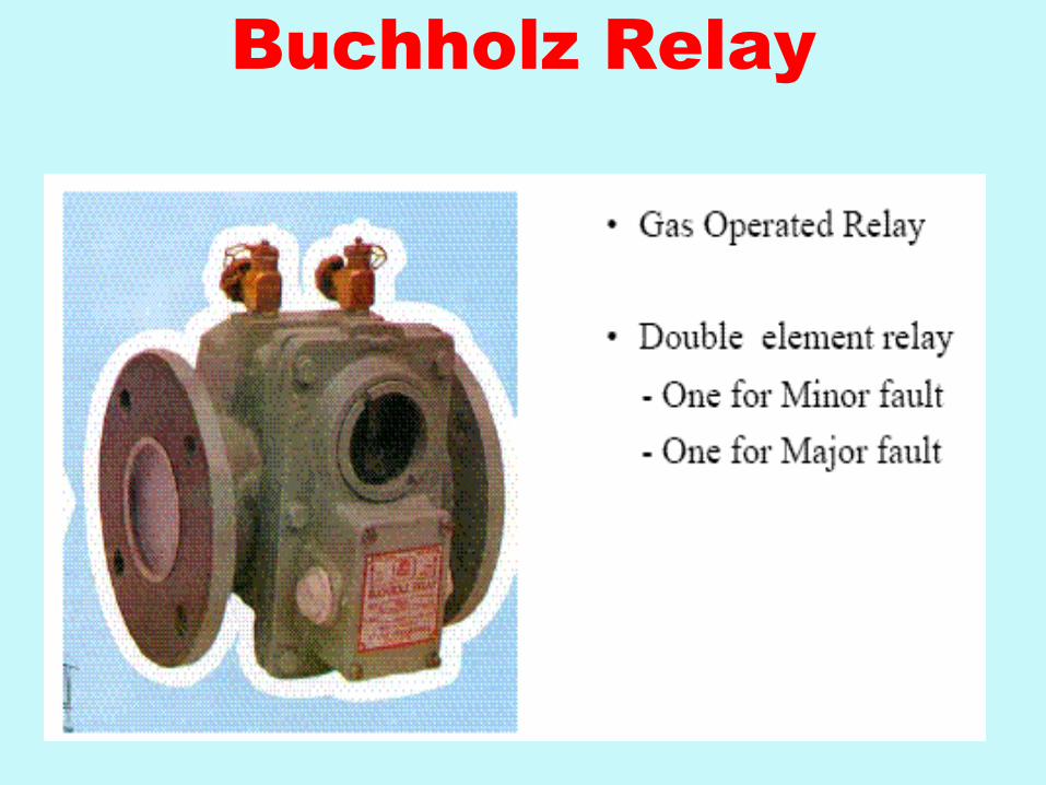
Buchholz Relay

24 May 2012 PMI Revision 00 35
Buchholz's Relay
• This has two Floats, one of them with surge catching baffle and
gas collecting space at top. This is mounted in the connecting pipe line between conservator and main tank.This is the most dependable protection for a given transformer.
• Gas evolution at a slow rate, that is associated with minor faults inside the transformers gives rise to the operation of top float whose contacts are wired for alarm. There is a glass window with marking to read the volume of gas collected in the relay. Any major fault in transformer creates a surge and the surge element in the relay trips the transformer. Size of the relay varies with oil volume in the transformer and the mounting angle also is specified for proper operation of the relay.

24 May 2012 PMI Revision 00 36

24 May 2012 PMI Revision 00 37
• Alarm element Operates When a specified volume of
gas gets collected in Chamber during
Broken down core bolt insulation
Shorted Laminations
Bad Contacts
Overheating of winding parts
• Trip element Operates by Oil surge in the event of
serious fault
Short Circuit between Winding Phases or
within Windings
Puncture of Bushing
BUCHHOLZ PROTECTION

24 May 2012 PMI Revision 00 38

24 May 2012 PMI Revision 00 39
Off Load Tap Changer

24 May 2012 PMI Revision 00 40

24 May 2012 PMI Revision 00 41
Conservator
• Conservator With the variation of temperature there is corresponding variation in the oil volume. To account for this, an expansion vessel called conservator is added to the transformer with a connecting pipe to the main tank. In smaller transformers this vessel is open to atmosphere through dehydrating breathers (to keep the air dry). In larger transformers, an air bag is mounted inside the conservator with the inside of bag open to atmosphere through the breathers and the outside surface of the bag in contact with the oil surface.

24 May 2012 PMI Revision 00 42
Buchholtz relay

24 May 2012 PMI Revision 00 43
SILICA GEL BREATHER
conservator

24 May 2012 PMI Revision 00 44
Breather
• Both transformer oil and cellulosic paper are highly hygroscopic. Paper being more hygroscopic than the mineral oil The moisture, if not excluded from the oil surface in conservator, thus will find its way finally into the paper insulation and causes reduction insulation strength of transformer. To minimise this the conservator is allowed to breathe only through the silicagel column, which absorbs the moisture in air before it enters the-conservator air surface.

24 May 2012 PMI Revision 00 45
•The Drycol Breather (A) operates by drawing moist, warm air (B) from an air space or from outside via the air inlet tube (C), and returning it to the conservator (D) as cold dry air. A series of thermoelectric modules are used to alternately cool and heat the units vertical central duct (E) in an automatic continuously repeated cycle, extracting moisture as frost and ice, and melting it to escape via a drain tube (F).

24 May 2012 PMI Revision 00 46
Winding / Oil Temperature Indicator

24 May 2012 PMI Revision 00 47
Pressure Relief Device/Expansion vent
• Transformers tank is a pressure vessel as the
inside pressure can group steeply whenever
there is a fault in the windings and the
surrounding oil is suddenly vaporized. Tanks as
such are tested for a pressure with stand
capacity of 0.35 Kg/ cm". To prevent bursting of
the tank, these tanks are in addition provided with
expansion vents with a thin diaphragm made of
bakelite/copper/glass at the end. In present day
transformers, pressure relief devices are
replacing the expansion vents. These are similar
to safety valves on boilers (spring loaded).

24 May 2012 48
Pressure Relief Device( PRD)

24 May 2012 PMI Revision 00 49
Temperature Indicators
• Most of the transformer (small transformers have
only OTI) are provided with indicators that displace oil temperature and winding temperature. There are thermometers pockets provided in the tank top cover which hold the sensing bulls in them. Oil temperature measured is that of the top oil, where as the winding temperature measurement is indirect. This is done by adding the temperature rise
• due to the heat produced in a heater coil (known as image coil) when a current proportional to that flowing in windings is passed in it to that or top oil. For proper functioning or OTI & WTI it is essential to keep the thermometers pocket clean and filled with oil.

24 May 2012 PMI Revision 00 50
Cooling of Transformers
• Heat is produced in the windings due to current flowing in
the conductors (I- R) and in the core on account of eddy
currents and hysteresis losses.
Types: ONAN, ONAF, OFAF, OFWF
• Air Cooled: In small dry type transformer heat is dissipated
directly to the atmosphere.
• Oil Cooled: In oil immersed transformers heat is dissipated
by thermo-syphon system action. The oil serves as the
medium for transferring the heat produced inside the
transformer to the outside atmosphere. Based on Thermo-
syphon principle.

24 May 2012 PMI Revision 00 51
Cooling of Transformers
• Forced Oil forced Air: As the size of the transformer becomes large, the rate of oil circulating by thermo syphon action becomes insufficient to dissipate all the heat produced and an artificial means of increasing the circulation have to be adopted; namely forced oil circulation by electric pumps, providing large radiators with forced air draft, cooling by electric fans which are automatically switched on and off depending upon the loading of transformer. In very large transformers special coolers with water circulation may have to be employed.

24 May 2012 PMI Revision 00 52
Different transformers in a power
Plant
• Generator Transformer (GT)
Station Transformer (ST)
Unit Auxiliary Transformer (UAT)
Excitation Transformer
Neutral Grounding Transformer
Auxiliary transformers
Tie / Auto transformer

24 May 2012 PMI Revision 00 53
Generator Transformer
• Generator Transformer The generator is connected to this transformer by means of isolated bus ducts. This transformer is used to step up the generating voltage of around 15KV to grid voltage. This transformer is generally provided with OFAF cooling. It is also provided with off circuit/on load taps on the high voltage side. This transformer has elaborate cooling system consisting of number of oil pumps and cooling fans apart from various accessories.

24 May 2012 PMI Revision 00 54
SPECIFICATION
STAGE -1 GT-Vindhyachal
RATED O/P 250MVA
RATED VOLT. (HV) 420KV
RATED VOLT. (LV) 15.75KV
RATED CURRENT(HV) 344A
RATED CURRENT(LV) 9175A
VECTOR GROUP Ynd11

24 May 2012 PMI Revision 00 55
Unit Auxiliary Transformer
• The UAT draws its input from the main bus-duct
connecting generator to the generator Transformer. The total
KVA capacity of unit auxiliary transformer required can be
determined by assuming 0.85 power factor and 0.9 efficiency
for total auxiliary motor load. It is safe and desirable to
provide about 20% excess capacity than circulate so as to
provide for miscellaneous auxiliaries and possible increase
in auxiliary load. With higher unit ratings and higher steam
conditions, the auxiliary power required also increases and
limitations imposed by the switchgear voltages available,
indicate the maximum size of unit auxiliary transformer which
can be used.

24 May 2012 PMI Revision 00 56
UAT
• For large units, it has become necessary to use more than one auxiliary transformer. In selecting a unit auxiliary transformer, care has to be taken that the percentage impedences of the transformers for the proposed unit should satisfy the following conflicting requirements.
• The maximum short circuit currents on auxiliary bus should be limited within the maximum switchgear rating available,
• The maximum permissible voltage dip while starting the largest single auxiliary motor, usually boiler feed pump, shall remain within acceptable limits.

24 May 2012 PMI Revision 00 57
GENERATOR
7UA 7UB
SA SB
GT (3X200 MVA)
Unit Tx 21/11 K.V. (50 MVA)
IN THE EVENT OF UNIT TRIPPING AUTO CHANGEOVER FROM UT TO STATION WILL TAKE PLACE

24 May 2012 PMI Revision 00 58
Station Transformers
• The station transformer is required to feed power to the auxiliaries during start ups. This transformer is normally rated for the initial auxiliary load requirements of unit. In typical cases, this load is of the order of 60% of the load at full generating capacity. But in large stations where more than one units are operating, the station transformers should have sufficient capacity to start two units at a time in addition to feeding the common auxiliaries. It is also provided with on load tap changer to cater to the fluctuating voltage of the grid.

24 May 2012 PMI Revision 00 59

24 May 2012 PMI Revision 00 60
Instrument Transformers
• . Step down values to safe levels for measurement
• . Potential Transformers
• . Also called voltage transformers
• . Standard output 110V
• . Current Transformers
• . Standard output of 1 or 5 amps
• . Metering and relaying standards
• . Can produce high voltages if open circuited

24 May 2012 PMI Revision 00 61
Rectifier transformers
• Output of the main transformer is connected to the
rectifier unit.

24 May 2012 PMI Revision 00 62
Transformer connections :
- Delta/Star…used in Generating stations for Step-up.
- Star/Delta…used in Receiving stations for Step-
down
* All GTs are Delta/Star connected.
All Tie T/Fs are Star/Star connected.

24 May 2012 PMI Revision 00 63
STAR / DELTA connection
STAR / STAR connection

24 May 2012 PMI Revision 00 64
STAR DELTA

24 May 2012 PMI Revision 00 65
Transformer losses
1. Load loss (or copper loss)
2. No load loss (or iron loss)
• The total transformer loss, PTOTAL, at any load
level can then be calculated from:
PTOTAL = PNO-LOAD+ (% Load)2 x PFULL LOAD

24 May 2012 PMI Revision 00 66

24 May 2012 PMI Revision 00 67
Transformer Loss vs. Load

24 May 2012 PMI Revision 00 68
TRANSFORMER LOSSES
Winding resistance
Current flowing through the windings causes resistive heating of the conductors (I2 R loss). At higher frequencies, skin effect and proximity effect create additional winding resistance and losses.
• Magnetostriction
Magnetic flux in the core causes it to physically expand and contract slightly with the alternating magnetic field, an effect known as magnetostriction. This in turn causes losses due to frictional heating in susceptible ferromagnetic cores.

24 May 2012 PMI Revision 00 69
TRANSFORMER LOSSES
• Stray losses
Not all the magnetic field produced by the primary is intercepted by the secondary. A portion of the leakage flux may induce eddy currents within nearby conductive objects, such as the transformer's support structure, and be converted to heat.

24 May 2012 PMI Revision 00 70
Copper Losses

24 May 2012 71
On-Line
Monitoring

24 May 2012 PMI Revision 00 72
ON LINE MONITORING EQUIPMENT ON TRANSFORMER
1. DGA to be monitored on all transformers periodically. Periodicity
depends on the nature of evaluation of gases.
2. HYDRANE directly mounted on the transformer and in contact with
transformer oil.
The use of this device is to detect the change in fault gases, to
monitor their evolution. As an alarm is triggered oil is sampled
from the transformer to evaluate the nature and severity of the
fault.

24 May 2012 PMI Revision 00 73
7. ON LINE MONITORING EQUIPMENT ON TRANSFORMER Contd.
3. Acoustic PD measurement.
In case DGA results indicate the presence of high discharges
Acoustic PD measurement is done.
Acoustic PD detector consists of sensor which can sense sound
vibrations produced due to occurrence of discharges in oil.
The sensor has pre-amplifier and filter circuit to eliminate
environmental noise
4 Infrared thermography
With the help of infrared thermo-vision camera, the thermo-image
of transformer is prepared
This scanning helps in detecting overheated zones, loose &
corroded connection.

24 May 2012 PMI Revision 00 74
• CONDITION MONITORING OF TRANSFORMER
• Since Regular Internal Inspection of the transformers is not possible
• Only "Diagnostic tests" mentioned below are possible:
• Dissolved Gas Analysis (DGA) of insulating oil
• - the most significant hydrocarbons (gases) generated due to decomposition of oil are:
• Hydrogen (h2)
• Methane (ch4)
• Ethane (c2h6)
• Ethylane (c2h4)
• Acctelene (c2h2)
• Due to decomposition of cellulose: co and co2 are formed
• Partial Discharge (PD) Tests.
• Sonic and Ultrasonic detection
• Infrared Thermographic inspection

24 May 2012 PMI Revision 00 75
OFF LINE MONITORING
1. Frequency Response Analysis
• Short circuit forces could move the winding.
• Can also change winding inductance and capacitance.
• Conventional tests are not sensitive to winding movement.
• Such changes can be effectively detected by FRA
Method
• Sweep frequency input is given in the winding.
• Input & response recorded.
• FFT analysis of response to obtain the finger print of the winding.
• These finger prints are compared periodically to assess the condition of winding.

24 May 2012 PMI Revision 00 76
2. Recovery voltages measurement
It indicates the content of water in the insulation.
PRINCIPLE
•Sample of discharged insulation
•Charge with DC voltage and note time
•Sample to be short circuited for predetermined period of time
( approximately half of the charged time)
•Open the terminal and measure voltage.
3. Tan- & Capacitance by standard bridge.

24 May 2012 PMI Revision 00 77
4. Resistance & magnetizing current.
5. Maintenance schedule call for daily , quarterly, yearly, two
yearly maintenance requirement. Over and above after 7 to
10 years, thorough overhauling and inspection of core-coil
assembly by lifting tank top cover / core-coil assembly
needed
In overhauling sludge deposited on coil is removed and coil
assembly which may become loose is tightened. All other
clampings & cleats etc. are also tightened

24 May 2012 PMI Revision 00 78
THANK YOU

24 May 2012 PMI Revision 00 79
• IEC-International Electrotechnical Commission
• IEEE-Institute of Electrical and Electronics
Engineers