Embed Size (px)
Citation preview
GE Digital Energy
GE Information
D20MX Processor
Hardware User’s Manual
994-0140Version 1.10 Revision 0
GE Digital Energy
Copyright Notice© 2012 - 2013, General Electric Company. All rights reserved.
The information contained in this online publication is the exclusive property of General Electric Company, except as otherwise indicated. You may view, copy and print documents and graphics incorporated in this online publication (the “Documents”) subject to the following: (1) the Documents may be used solely for personal, infor-mational, non-commercial purposes; (2) the Documents may not be modified or altered in any way; and (3) Gen-eral Electric Company withholds permission for making the Documents or any portion thereof accessible via the internet. Except as expressly provided herein, you may not use, copy, print, display, reproduce, publish, license, post, transmit or distribute the Documents in whole or in part without the prior written permission of General Electric Company.
The information contained in this online publication is proprietary and subject to change without notice. The software described in this online publication is supplied under license and may be used or copied only in accor-dance with the terms of such license.
Trademark Notices
GE and are trademarks and service marks of General Electric Company.
* Trademarks of General Electric Company.
ERNI is a registered trademark of ERNI Elektroapparate GMBH. Hyperterminal is a registered trademark of Hil-graeve, Tera Term is a registered trademark of T. Teranishi, Incorporated. IEC is a registered trademark of Com-mission Electrotechnique Internationale. IEEE is a registered trademark of the Institute of Electrical and Electronics Engineers, Inc. Internet Explorer, Microsoft, and Windows are registered trademarks of Microsoft Cor-poration. JAVA and J2SE are registered trademarks of Sun Microsystems, Inc. Maxell is a registered trademark of Hitachi Maxell, Ltd. MiniSQL is a trademark of Hughes Technologies. Modbus is a registered trademark of Schnei-der Automation Inc. Panduit is a registered trademark of Panduit Corp. Saft is a registered trademark of SAFT société anonyme. SEL is a registered trademark of Schweitzer Engineering Laboratories, Inc. Silicon Systems is a registered trademark of Silicon Systems, Inc. Sonnenschein is a registered trademark of Deutsche Exide GMBH. Tadiran is a registered trademark of Tadiran Israel Electronics Industries Ltd. Toshiba is a registered trademark of Kabushiki Kaisha Toshiba, doing business as Toshiba Corporation. VESA is registered trademark of Video Elec-tronics Standards Association Corporation.
Other company or product names mentioned in this document may be trademarks or registered trademarks of their respective companies.
This printed manual is recyclable.Please return for recycling where facilities exist.
D20MX HARDWARE USER’S MANUAL GE INFORMATION 3
D20MX Processor
Table of contents
ABOUT THIS DOCUMENT
Purpose ............................................................................................................................7Intended audience ........................................................................................................7Additional documentation ...........................................................................................7How to use this manual ................................................................................................8Document conventions .................................................................................................8Safety words and definitions........................................................................................9
PRODUCT SUPPORT Search technical support ...........................................................................................11Contact customer support ........................................................................................11Product returns.............................................................................................................12Upgrade your D20MX processor firmware ..............................................................12
BEFORE YOU START Safety precautions ......................................................................................................13Warning symbols ......................................................................................................................................... 14
Regulatory compliance information ........................................................................14CE Mark compliance .................................................................................................................................... 14Export control classification number ...................................................................................................15
Product overview..........................................................................................................15Product design................................................................................................................................................ 15D20MX Processor ......................................................................................................................................... 15Security .............................................................................................................................................................. 16D20MX applications .................................................................................................................................... 16Firmware/FPGA versions ........................................................................................................................... 18D20 chassis ...................................................................................................................................................... 18Power supply ................................................................................................................................................... 21Modems ............................................................................................................................................................. 22Peripherals........................................................................................................................................................ 22
Ordering guide..............................................................................................................23D20MX upgrade kits.....................................................................................................24Product specifications ................................................................................................25Storage recommendations.........................................................................................27
Storage conditions ...................................................................................................................................... 27
4 GENERAL D20MX HARDWARE USER’S MANUAL
TABLE OF CONTENTS
INSTALLING THE D20MX
D20 chassis layouts .....................................................................................................29Installation steps..........................................................................................................31Retrofitting the D20MX in an existing D20 ..............................................................33Required tools and materials.....................................................................................35Grounding the D20MX .................................................................................................36Unpacking the D20MX .................................................................................................36
Package contents ..........................................................................................................................................36Connecting the power supply ....................................................................................36
CONNECTING TO DEVICES AND NETWORKS
Cabling overview ..........................................................................................................39D20MX front panel connectors ...............................................................................................................39General cabling requirements .................................................................................................................40
Serial ...............................................................................................................................41D.20 Link.........................................................................................................................41Twisted-pair Ethernet (for 526-3001 only) ...............................................................42Fiber optic Ethernet (for 526-3003 and 526-3005LF only).....................................43LAN redundancy ...........................................................................................................44IP addresses ..................................................................................................................44RS-232.............................................................................................................................47D20 system redundancy .............................................................................................47
Failover sequence..........................................................................................................................................49Required components .................................................................................................................................49RS-232 switch panel operation ...............................................................................................................50Redundancy wiring diagrams..................................................................................................................50
POWERING-UP AND TESTING
Required for testing .....................................................................................................53Accessing WESMAINT II+ using a terminal.........................................................................................54Terminal Emulation.......................................................................................................................................54SHELL...................................................................................................................................................................54
Power up and test steps..............................................................................................54Set up a PC to act as a WESMAINTII+ terminal .......................................................55Power up the D20MX....................................................................................................55Automatic on-line start-up test.................................................................................55
Code and configuration files ....................................................................................................................56Further testing.................................................................................................................................................56
Test for redundancy.....................................................................................................56Check that fail-over is functioning correctly...........................................................57Check that switch-over is functioning correctly ....................................................57Verify either hardware or software switch-over ....................................................58
CONFIGURING THE SOFTWARE
Introduction to the D20MX software ........................................................................59D20MX user accounts ..................................................................................................59
Remote and local user accounts............................................................................................................60Factory default user account ..................................................................................................................60System default user account ...................................................................................................................60
Download image files to the D20MX.........................................................................61When to download........................................................................................................................................61Prerequisites for image download.........................................................................................................61Download software over a serial connection...................................................................................61
TABLE OF CONTENTS
D20MX HARDWARE USER’S MANUAL GENERAL 5
Download software over a network connection............................................................................ 64SGConfig firmware options ........................................................................................65Update to the SAN0001 firmware option.................................................................66Migrate D20MX application definitions to SGConfig..............................................69Transfer D20/D200 configurations to the D20MX .................................................69
Transferring a D20 configuration to the D20MX ............................................................................ 70Transferring a D200 configuration to the D20MX.......................................................................... 76
Updating D20/D200 configurations to use the D20MX firmware definition with ConfigPro.............................................................................................................77
Updating a D20 configuration to use the D20MX firmware definition with ConfigPro 77Updating a D200 configuration to use the D20MX firmware definition with ConfigPro ..
79
USING THE D20MX Front panel LEDs ..........................................................................................................81Operational status LEDs............................................................................................................................. 81LAN port status LEDs ................................................................................................................................... 82Fiber optic port status LEDs ..................................................................................................................... 82
DEFAULT ROLE-BASED ACCESS CONTROL MODEL
Configured roles in the D20MX ..................................................................................83
SERVICING THE D20MX
Performing periodic inspection ................................................................................89Removing the D20MX processor module ................................................................89
STANDARDS & PROTECTION
Compliance standards ................................................................................................91
LIST OF ACRONYMS Acronym Definitions ....................................................................................................95
Modification Record .................................................................................................................................. 103

6 GENERAL D20MX HARDWARE USER’S MANUAL
TABLE OF CONTENTS
D20MX HARDWARE USER’S MANUAL GE INFORMATION 7
D20MX Processor
About this Document
About this Document
Purpose
This manual provides information about installing, setting up, using and maintaining your D20MXTM Processor. This manual does not provide any procedures for configuring the software of the D20MX.
Intended audience
This manual is intended for use by field technicians and maintenance personnel who are responsible for the installation, wiring and maintenance of SCADA equipment. This manual assumes that the user is experienced in:
• Electrical utility applications
• Electrical wiring and safety procedures
• Related other manufacturers’ products, such as protective relays and communications equipment
Additional documentation
For the most current version of the D20MX Hardware User's Manual, please download a copy from: http://www.gedigitalenergy.com/app/ViewFiles.aspx?prod=d20mx&type=3For further information about the D20MX, refer to the following documents.
• SGConfigTM Online Help
• D20/D200 Installation and Operation Guide, 994-0078
• Application Configuration Guides and User Guides (available on the D20MX Documentation CD)
8 GE INFORMATION D20MX HARDWARE USER’S MANUAL
ABOUT THIS DOCUMENT
How to use this manual
This manual describes how to install the D20MX and get it up and running for the first time.Procedures are provided for all component options available for the D20MX. The components included in your D20MX depend on what was ordered for your substation application. The software-related procedures in this manual are based on using a computer running Windows® XP. Some steps and dialog boxes may vary slightly if you are using another version of Windows.
Document conventions
The following typographic conventions are used throughout this manual:Bold face is used for:
• Names of software program menus, editors, and dialog boxes; also for the names of menu commands, keyboard keys, icons and desktop shortcuts, and buttons and fields in editors and dialog boxes
• Names of hardware components
• User input that must be typed exactly
Italic face is used for:
• Emphasis
• Cross-references to sections, figures and tables within this manual and for titles of other documents
• File and directory names; examples of directory paths are generally given in the Windows format
• Placeholders for user input that is specific to the user. May also include angle brackets around the placeholder if the placeholder is already in italic text. For example, c:\<product>\product.def
• References to a parameter or field value shown

ABOUT THIS DOCUMENT
D20MX HARDWARE USER’S MANUAL GE INFORMATION 9
Safety words and definitions
Before attempting to install or use the device, review all safety indicators in this document to help prevent injury, equipment damage or downtime.The following safety and equipment symbols are used in this document:
Indicates a hazardous situation which, if not avoided, will result in death or serious injury.
Indicates a hazardous situation which, if not avoided, could result in death or serious injury.
Indicates a hazardous situation which, if not avoided, could result in minor or moderate injury.
Indicates practices that are not related to personal injury.

10 GE INFORMATION D20MX HARDWARE USER’S MANUAL
ABOUT THIS DOCUMENT
D20MX HARDWARE USER’S MANUAL GE INFORMATION 11
D20MX Processor
Product Support
Product Support
If you need help with any aspect of your GE Digital Energy product, you have a few options.
Search technical support
The GE Digital Energy Web site provides fast access to technical information, such as manuals, release notes and knowledge base topics at:
http://www.gedigitalenergy.com
Contact customer support
The GE Digital Energy Customer Service Center is open 24 hours a day, seven days a week for you to talk directly to a GE representative.In the U.S. and Canada, call toll-free: 1 800-547-8629International customers, please call: + 1 905-927-7070Or e-mail to [email protected] Have the following information ready to give to Customer Service:
• Ship to address (the address that the product is to be returned to)
• Bill to address (the address that the invoice is to be sent to)
• Contact name
• Contact phone number
• Contact fax number
• Contact e-mail address
• Product number / serial number
• Description of problem
The Customer Service centre will provide you with a case number for your reference.

12 GE INFORMATION D20MX HARDWARE USER’S MANUAL
PRODUCT SUPPORT
Product returns
A Return Merchandise Authorization (RMA) number must accompany all equipment being returned for repair, servicing, or for any other reason. Before you return a product, please contact GE Digital Energy to obtain an RMA number and instructions for return shipments. You will be sent the RMA number and RMA documents via fax or e-mail. Once you receive the RMA documents, attach them to the outside of the shipping package and ship to GE.
NOTE
Product returns will not be accepted unless accompanied by the Return Merchandise Authorization number.
Upgrade your D20MX processor firmware
The firmware of your D20MX Processor can be upgraded to provide the latest functionality and improvements. Visit the customer support web site at http://www.gedigitalenergy.com to download the upgrade software and instruction guide.
D20MX HARDWARE USER’S MANUAL GE INFORMATION 13
D20MX Processor
Chapter 1: Before You Start
Before You Start
The new D20MX processor card is a pin-for-pin compatible replacement for all generations of the D20 SBC, providing the latest revisions of common D20 applications and performance enhancements to support NERC-compliant Cyber security. Before you begin installing and using the D20MX, review the information in this chapter, including the following topics:
• Safety precautions
• Regulatory compliance information
• Product overview
• Product specifications
• Storage recommendations
Read and thoroughly understand this manual before installing and operating the unit. Save these instructions for later use and reference.
WARNING! Failure to observe the instructions in this manual may result in serious injury or death.
Safety precautions
Follow all safety precautions and instructions in this manual.Only qualified personnel should work on the D20MX. Maintenance personnel should be familiar with the technology and the hazards associated with electrical equipment.
• Never work alone.
• Before performing visual inspections, tests, or maintenance on this equipment, isolate or disconnect all hazardous live circuits and sources of electric power. Assume that all circuits are live until they have been completely de-energized, tested, and tagged. Pay particular attention to the design of the power system. Consider all sources of power, including the possibility of back feed.
• Turn off all power supplying the equipment in which the D20MX is to be installed before installing and wiring the D20MX.
• Operate only from the power source specified on the installed power supply module.
• Beware of potential hazards and wear personal protective equipment.
14 GE INFORMATION D20MX HARDWARE USER’S MANUAL
CHAPTER 1: BEFORE YOU START
• The successful operation of this equipment depends upon proper handling, installation, and operation. Neglecting fundamental installation requirements may lead to personal injury as well as damage to electrical equipment or other property.
• All AC voltage terminals are protected from accidental contact by a mechanical safety shield.
• All electronic components within the D20MX are susceptible to damage from electrostatic discharge. To prevent damage when handling this product use approved static control procedures.
• Hazardous voltages can cause shock, burns or death. To prevent exposure to hazardous voltages, disconnect and lock out all power sources before servicing and removing components.
• If the D20MX is used in a manner not specified in this manual, the protection provided by the equipment may be impaired.
• Changes or modifications made to the unit not authorized by GE Digital Energy could void the warranty.
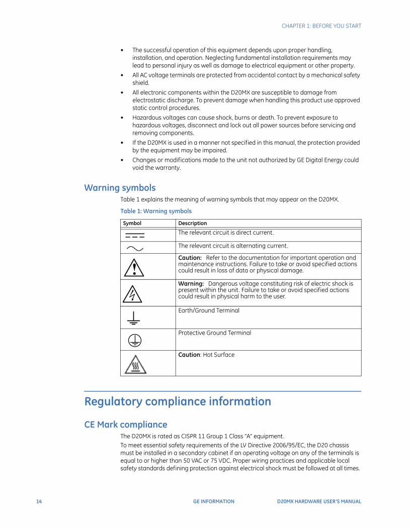
Warning symbols Table 1 explains the meaning of warning symbols that may appear on the D20MX.
Table 1: Warning symbols
Regulatory compliance information
CE Mark complianceThe D20MX is rated as CISPR 11 Group 1 Class “A” equipment.To meet essential safety requirements of the LV Directive 2006/95/EC, the D20 chassis must be installed in a secondary cabinet if an operating voltage on any of the terminals is equal to or higher than 50 VAC or 75 VDC. Proper wiring practices and applicable local safety standards defining protection against electrical shock must be followed at all times.
Symbol Description
The relevant circuit is direct current.
The relevant circuit is alternating current.
Caution: Refer to the documentation for important operation and maintenance instructions. Failure to take or avoid specified actions could result in loss of data or physical damage.
Warning: Dangerous voltage constituting risk of electric shock is present within the unit. Failure to take or avoid specified actions could result in physical harm to the user.
Earth/Ground Terminal
Protective Ground Terminal
Caution: Hot Surface
!
CHAPTER 1: BEFORE YOU START
D20MX HARDWARE USER’S MANUAL GE INFORMATION 15
NOTE
To provide higher EMC immunity and maintain CE Mark compliance, the serial cables used for permanent RS-232 and RS-485 connections must comply with the following requirements:
• Cables must be shielded
• D type connector covers must provide EMC shielding (e.g., metallized plastic or die cast metal covers) for permanently connected RS-232 cables
Class “A” equipment is intended for use in an industrial environment. The equipment generates, uses and can radiate radio frequency energy and, if not installed and used in accordance with these instructions, may cause interference to other devices in the vicinity. If this equipment does cause interference with other devices, which can be determined by turning the equipment off and on, the user is encouraged to try to correct the interference by one or more of the following measures:• Reorient or relocate the receiving device• Increase the separation between the equipment• Connect the equipment into an outlet on a circuit different from that to which the
other device(s) is connected• Consult the manufacturer or field service technician for help
Export control classification numberThe Export Control Classification Number (ECCN) of the D20MX hardware is 4A994.
Product overview
The D20 is a standalone remote terminal unit (RTU). It consists of a D20MX processor board, power supply, optional termination panels, and optional communications equipment in a 3U tall, 19-inch wide chassis. These components, combined with software applications running on the D20MX, form the D20 RTU System.The D20 acts as a data concentrator and central processor. Field data gathered through the peripheral modules and external Intelligent Electronic Devices (IEDs) are stored in the system database and can be accessed by the application programs loaded on the D20.
Product designThe D20 design has horizontally mounted processor boards, with multiple boards in some versions.Peripheral I/O boards operate independently of the main chassis and D20MX processor board. This means that you can use a D20 without direct connection to peripheral boards so that it acts as a master data concentrator to other RTUs. You can also hot-swap the peripherals without powering down the main processor. For information on peripheral modules, see the D20/D200 Installation and Operations Guide (part number 994-0078); see section: Connections and Configuration.
D20MX Processor The D20MX is a single board computer built around a 667 MHz embedded PowerQUICC II Pro processor. The D20MX permits the D20 to be NERC CIPS compliant and introduces compliance to IEC standards; refer to Appendix A, Standards & Protection for the complete listing.
16 GE INFORMATION D20MX HARDWARE USER’S MANUAL
CHAPTER 1: BEFORE YOU START
The D20MX can be retrofitted into either a D20 3U single-node VME chassis or D20 3U non-VME chassis. In a single-node VME chassis, this one processor module replaces the previous D20 M, M++, ME, and MEII CPU cards.Due to aging printed circuit board assembly and mechanical constraints, only certain chassis from 2002 and onward can be used with a D20MX. This comprises the following chassis:
• D20 VME chassis 500-0280 Release 08 or higher,
• D20 Non-VME chassis 500-0305 Release 18 or higher
A solid partition between the Main processor bay and accessory bay prevents access to the harness from the fiber card to D20MX card (only applicable to the 526-3005LF fiber card version).
SecurityThe D20MX provides the following new security improvements over its predecessors:
• Centralized user authentication and authorization (RADIUS), including integration with Microsoft Servers using NPS
• Role Based Access Control (RBAC) keeping operator and engineering activities separated, logged and simple
• NERC compliant passwords, with strong complexity rules and one-way encrypted
• Full auditing including Syslog integration to enterprise systems
• SFTP for secure network-based firmware upgrades and configuration file transfers
• SSH for secure network access to WESMAINT II+.
To take advantage of these improvements, refer to the WESMAINT II+ for the D20MX Configuration Guide (B014-1NCG) for details of these security features of the D20MX
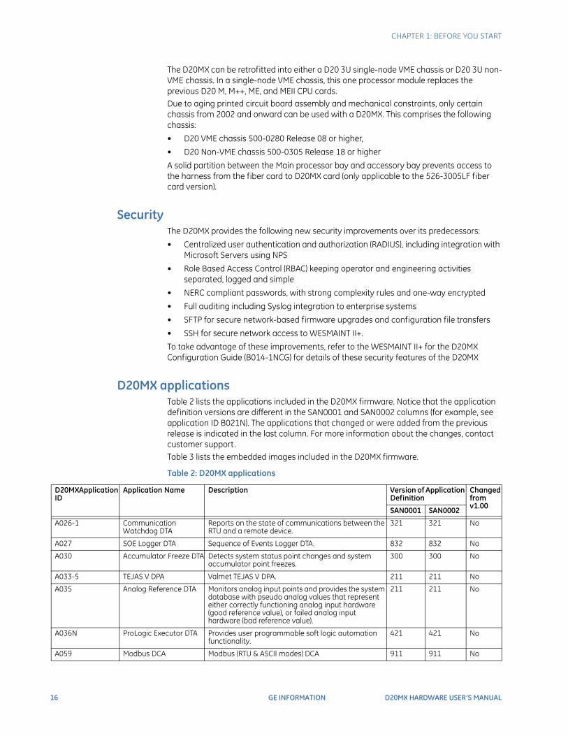
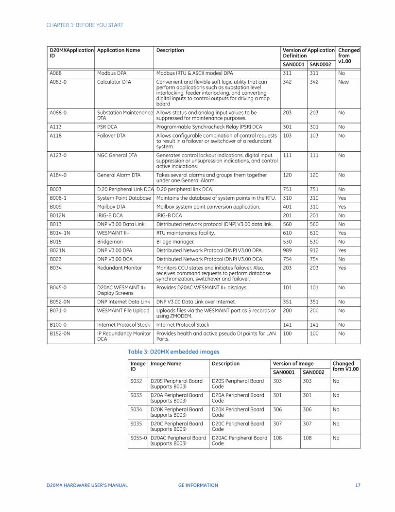
D20MX applications Table 2 lists the applications included in the D20MX firmware. Notice that the application definition versions are different in the SAN0001 and SAN0002 columns (for example, see application ID B021N). The applications that changed or were added from the previous release is indicated in the last column. For more information about the changes, contact customer support.Table 3 lists the embedded images included in the D20MX firmware.
Table 2: D20MX applications
D20MXApplication ID
Application Name Description Version of Application Definition
Changed from v1.00
SAN0001 SAN0002
A026-1 Communication Watchdog DTA
Reports on the state of communications between the RTU and a remote device.
321 321 No
A027 SOE Logger DTA Sequence of Events Logger DTA. 832 832 No
A030 Accumulator Freeze DTA Detects system status point changes and system accumulator point freezes.
300 300 No
A033-5 TEJAS V DPA Valmet TEJAS V DPA. 211 211 No
A035 Analog Reference DTA Monitors analog input points and provides the system database with pseudo analog values that represent either correctly functioning analog input hardware (good reference value), or failed analog input hardware (bad reference value).
211 211 No
A036N ProLogic Executor DTA Provides user programmable soft logic automation functionality.
421 421 No
A059 Modbus DCA Modbus (RTU & ASCII modes) DCA 911 911 No
CHAPTER 1: BEFORE YOU START
D20MX HARDWARE USER’S MANUAL GE INFORMATION 17
Table 3: D20MX embedded images
A068 Modbus DPA Modbus (RTU & ASCII modes) DPA 311 311 No
A083-0 Calculator DTA Convenient and flexible soft logic utility that can perform applications such as substation level interlocking, feeder interlocking, and converting digital inputs to control outputs for driving a map board
342 342 New
A088-0 Substation Maintenance DTA
Allows status and analog input values to be suppressed for maintenance purposes.
203 203 No
A113 PSR DCA Programmable Synchrocheck Relay (PSR) DCA 301 301 No
A118 Failover DTA Allows configurable combination of control requests to result in a failover or switchover of a redundant system.
103 103 No
A123-0 NGC General DTA Generates control lockout indications, digital input suppression or unsupression indications, and control active indications.
111 111 No
A184-0 General Alarm DTA Takes several alarms and groups them together under one General Alarm.
120 120 No
B003 D.20 Peripheral Link DCA D.20 peripheral link DCA. 751 751 No
B008-1 System Point Database Maintains the database of system points in the RTU. 310 310 Yes
B009 Mailbox DTA Mailbox system point conversion application. 401 310 Yes
B012N IRIG-B DCA IRIG-B DCA 201 201 No
B013 DNP V3.00 Data Link Distributed network protocol (DNP) V3.00 data link. 560 560 No
B014-1N WESMAINT II+ RTU maintenance facility. 610 610 Yes
B015 Bridgeman Bridge manager. 530 530 No
B021N DNP V3.00 DPA Distributed Network Protocol (DNP) V3.00 DPA. 989 912 Yes
B023 DNP V3.00 DCA Distributed Network Protocol (DNP) V3.00 DCA. 754 754 No
B034 Redundant Monitor Monitors CCU states and initiates failover. Also, receives command requests to perform database synchronization, switchover and failover.
203 203 Yes
B045-0 D20AC WESMAINT II+ Display Screens
Provides D20AC WESMAINT II+ displays. 101 101 No
B052-0N DNP Internet Data Link DNP V3.00 Data Link over Internet. 351 351 No
B071-0 WESMAINT File Upload Uploads files via the WESMAINT port as S records or using ZMODEM.
200 200 No
B100-0 Internet Protocol Stack Internet Protocol Stack 141 141 No
B152-0N IP Redundancy Monitor DCA
Provides health and active pseudo DI points for LAN Ports.
100 100 No
D20MXApplication ID
Application Name Description Version of Application Definition
Changed from v1.00
SAN0001 SAN0002
Image ID
Image Name Description Version of Image Changed form V1.00
SAN0001 SAN0002
S032 D20S Peripheral Board (supports B003)
D20S Peripheral Board Code
303 303 No
S033 D20A Peripheral Board (supports B003)
D20A Peripheral Board Code
301 301 No
S034 D20K Peripheral Board (supports B003)
D20K Peripheral Board Code
306 306 No
S035 D20C Peripheral Board (supports B003)
D20C Peripheral Board Code
307 307 No
S055-0 D20AC Peripheral Board (supports B003)
D20AC Peripheral Board Code
108 108 No
18 GE INFORMATION D20MX HARDWARE USER’S MANUAL
CHAPTER 1: BEFORE YOU START
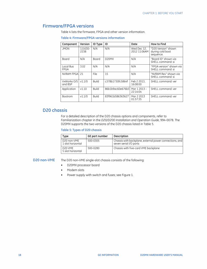
Firmware/FPGA versionsTable 4 lists the firmware, FPGA and other version information.
Table 4: Firmware/FPGA versions information
D20 chassisFor a detailed description of the D20 chassis options and components, refer to Familiarization chapter in the D20/D200 Installation and Operation Guide, 994-0078. The D20MX supports the two versions of the D20 chassis listed in Table 5.
Table 5: Types of D20 chassis
D20 non-VME The D20 non-VME single-slot chassis consists of the following:
• D20MX processor board
• Modem slots
• Power supply with switch and fuses; see Figure 1.
Component Version ID Type ID Date How to Find
JMON 1.0.630-2238
N/A N/A Wed Dec 12, 2012 11:06AM
“D20 Version” shown during cold boot sequence.
Board N/A Board D20MX N/A “Board ID” shown via SHELL command: si
Local Bus FPGA
3.02 N/A N/A N/A “FPGA version” shown via SHELL command: si
NVRAM FPGA 21 File 15 N/A “NVRAM Rev” shown via SHELL command: si
VxWorks O/S and BSP
v1.1/0 Build c378b1730fc5864f Feb 2 2013, 16:08:00
SHELL command: ver
Application v1.10 Build 86b1b9ac60e676b3 Mar 1 2013 - 22:14:04
SHELL command: ver
Bootrom v1.1/0 Build 83f961b586363627 Mar 2 2013 01:57:35
SHELL command: ver
Type GE part number Description
D20 non-VME1 slot horizontal
500-0305 Chassis with backplane, external power connections, and seven serial I/O ports
D20 VME5 slot horizontal
500-0280 Chassis with five-card VME backplane
CHAPTER 1: BEFORE YOU START
D20MX HARDWARE USER’S MANUAL GE INFORMATION 19
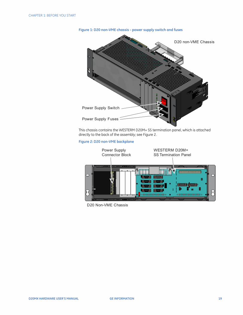
Figure 1: D20 non-VME chassis - power supply switch and fuses
This chassis contains the WESTERM D20M+ SS termination panel, which is attached directly to the back of the assembly; see Figure 2.
Figure 2: D20 non-VME backplane
D20 non-VME Chassis
Power Supply Switch
Power Supply Fuses
D20 Non-VME Chassis
Power Supply Connector Block
WESTERM D20M+ SS Termination Panel
20 GE INFORMATION D20MX HARDWARE USER’S MANUAL
CHAPTER 1: BEFORE YOU START
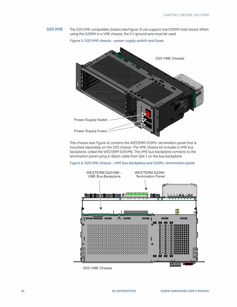
D20 VME The D20 VME-compatible chassis (see Figure 3) can support one D20MX main board. When using the D20MX in a VME chassis, the 0 V ground wire must be used.
Figure 3: D20 VME chassis - power supply switch and fuses
This chassis (see Figure 4) contains the WESTERM D20M+ termination panel that is mounted separately on the D20 chassis. The VME chassis kit includes a VME bus backplane, called the WESTERM D20VME. The VME bus backplane connects to the termination panel using a ribbon cable from Slot 1 on the bus backplane.
Figure 4: D20 VME chassis - VME bus backplane and D20M+ termination panel
D20 VME Chassis
Power Supply Switch
Power Supply Fuses
D20 VME Chassis
WESTERM D20VME - VME Bus Backplane
WESTERM D20M+ Termination Panel
CHAPTER 1: BEFORE YOU START
D20MX HARDWARE USER’S MANUAL GE INFORMATION 21
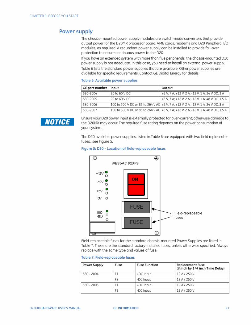
Power supplyThe chassis-mounted power supply modules are switch-mode converters that provide output power for the D20MX processor board, VME cards, modems and D20 Peripheral I/O modules, as required. A redundant power supply can be installed to provide fail-over protection to ensure continuous power to the D20.If you have an extended system with more than five peripherals, the chassis-mounted D20 power supply is not adequate. In this case, you need to install an external power supply.Table 6 lists the standard power supplies that are available. Other power supplies are available for specific requirements. Contact GE Digital Energy for details.
Table 6: Available power supplies
Ensure your D20 power input is externally protected for over-current; otherwise damage to the D20MX may occur. The required fuse rating depends on the power consumption of your system.
The D20 available power supplies, listed in Table 6 are equipped with two field replaceable fuses.; see Figure 5.
Figure 5: D20 - Location of field-replaceable fuses
Field-replaceable fuses for the standard chassis-mounted Power Supplies are listed in Table 7. These are the standard factory-installed fuses, unless otherwise specified. Always replace with the same type and values of fuse.
Table 7: Field-replaceable fuses
GE part number Input Output
580-2004 20 to 60 V DC +5 V, 7 A; +12 V, 2 A; -12 V, 1 A; 24 V DC, 3 A
580-2005 20 to 60 V DC +5 V, 7 A; +12 V, 2 A; -12 V, 1 A; 48 V DC, 1.5 A
580-2006 100 to 300 V DC or 85 to 264 V AC +5 V, 7 A; +12 V, 2 A; -12 V, 1 A; 24 V DC, 3 A
580-2007 100 to 300 V DC or 85 to 264 V AC +5 V, 7 A; +12 V, 2 A; -12 V, 1 A; 48 V DC, 1.5 A
Power Supply Fuse Fuse Function Replacement Fuse(¼inch by 1 ¼ inch Time Delay)
580 - 2004 F1 +DC Input 12 A / 250 V
F2 -DC Input 12 A / 250 V
580 - 2005 F1 +DC Input 12 A / 250 V
F2 -DC Input 12 A / 250 V
Field-replaceablefuses

22 GE INFORMATION D20MX HARDWARE USER’S MANUAL
CHAPTER 1: BEFORE YOU START
ModemsTwo D20 modems (can be purchased separately) for communications to a host computer or to other IEDs:
• WESDAC 202/V.23 is a 1200-baud Bell 202 or CCITT V.23 standard modem designed for 300 to 1200 baud asynchronous operation on unconditioned lines and supports the majority of SCADA/EMS applications. It is available in a 19 inch rack mount or 3U vertical mount configuration in the D20 chassis.
• WESDAC 212/V.23 is a 1200-baud Bell 212 standard modem, (auto answer only), used for dial-up access to the D20. This modem is available for mounting only as a 3U vertical mount.
Third-party modems can be used to meet specific requirements. These modems are connected to the D20 via standard RS-232 connections. Contact GE Digital Energy for more information on options.
PeripheralsPeripheral I/O modules are intelligent modules containing an on-board microprocessor. They are configured as slaves to the D20MX processor board. In this way, specific I/O processing is distributed throughout the RTU to the appropriate I/O module.There are five types of I/O peripherals:
• D20A analog input
• D20S digital inputs
• D20K digital output
• D20C combination input/output
• D20AC alternating current analog input
Optional high-voltage peripherals are also available.
580 - 2006 F1 Line/+DC Input 4 A / 250 V
F2 Neutral/-DC Input 4 A / 250 V
580 - 2007 F1 Line/+DC Input 4 A / 250 V
F2 Neutral/-DC Input 4 A / 250 V
Power Supply Fuse Fuse Function Replacement Fuse(¼inch by 1 ¼ inch Time Delay)
CHAPTER 1: BEFORE YOU START
D20MX HARDWARE USER’S MANUAL GE INFORMATION 23
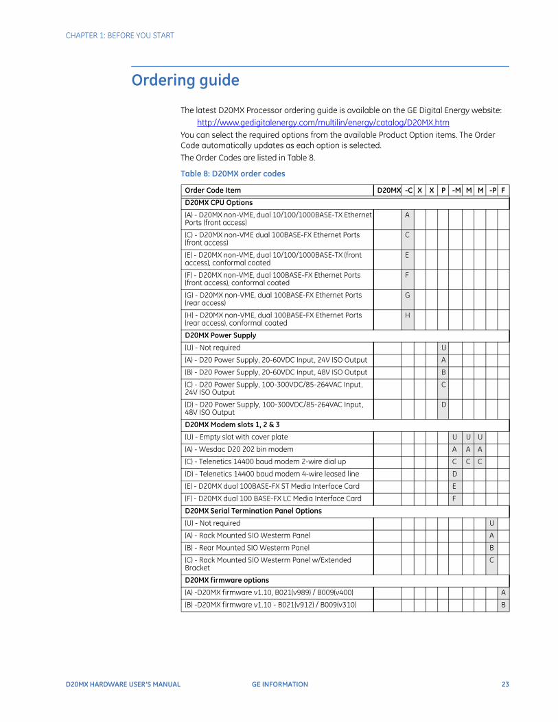
Ordering guide
The latest D20MX Processor ordering guide is available on the GE Digital Energy website:http://www.gedigitalenergy.com/multilin/energy/catalog/D20MX.htm
You can select the required options from the available Product Option items. The Order Code automatically updates as each option is selected.The Order Codes are listed in Table 8.
Table 8: D20MX order codes
Order Code Item D20MX -C X X P -M M M -P F
D20MX CPU Options
(A) - D20MX non-VME, dual 10/100/1000BASE-TX Ethernet Ports (front access)
A
(C) - D20MX non-VME dual 100BASE-FX Ethernet Ports (front access)
C
(E) - D20MX non-VME, dual 10/100/1000BASE-TX (front access), conformal coated
E
(F) - D20MX non-VME, dual 100BASE-FX Ethernet Ports (front access), conformal coated
F
(G) - D20MX non-VME, dual 100BASE-FX Ethernet Ports (rear access)
G
(H) - D20MX non-VME, dual 100BASE-FX Ethernet Ports (rear access), conformal coated
H
D20MX Power Supply
(U) - Not required U
(A) - D20 Power Supply, 20-60VDC Input, 24V ISO Output A
(B) - D20 Power Supply, 20-60VDC Input, 48V ISO Output B
(C) - D20 Power Supply, 100-300VDC/85-264VAC Input, 24V ISO Output
C
(D) - D20 Power Supply, 100-300VDC/85-264VAC Input, 48V ISO Output
D
D20MX Modem slots 1, 2 & 3
(U) - Empty slot with cover plate U U U
(A) - Wesdac D20 202 bin modem A A A
(C) - Telenetics 14400 baud modem 2-wire dial up C C C
(D) - Telenetics 14400 baud modem 4-wire leased line D
(E) - D20MX dual 100BASE-FX ST Media Interface Card E
(F) - D20MX dual 100 BASE-FX LC Media Interface Card F
D20MX Serial Termination Panel Options
(U) - Not required U
(A) - Rack Mounted SIO Westerm Panel A
(B) - Rear Mounted SIO Westerm Panel B
(C) - Rack Mounted SIO Westerm Panel w/Extended Bracket
C
D20MX firmware options
(A) -D20MX firmware v1.10, B021(v989) / B009(v400) A
(B) -D20MX firmware v1.10 - B021(v912) / B009(v310) B
24 GE INFORMATION D20MX HARDWARE USER’S MANUAL
CHAPTER 1: BEFORE YOU START
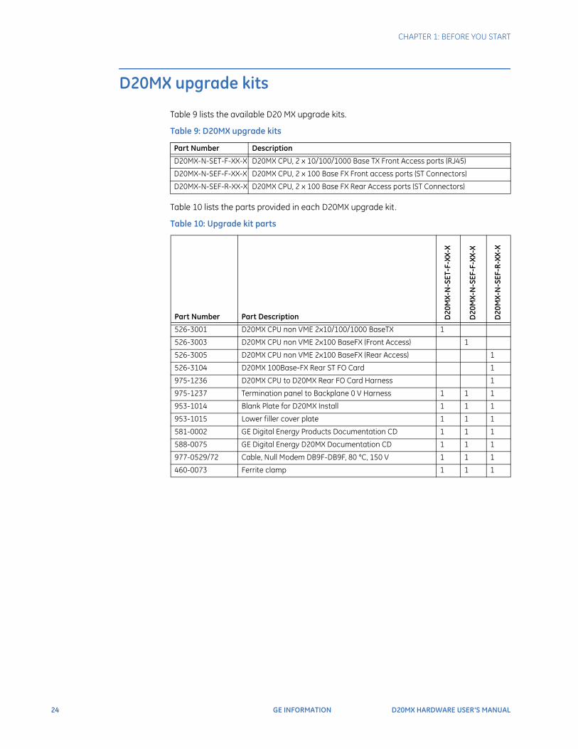
D20MX upgrade kits
Table 9 lists the available D20 MX upgrade kits.
Table 9: D20MX upgrade kits
Table 10 lists the parts provided in each D20MX upgrade kit.
Table 10: Upgrade kit parts
Part Number Description
D20MX-N-SET-F-XX-X D20MX CPU, 2 x 10/100/1000 Base TX Front Access ports (RJ45)
D20MX-N-SEF-F-XX-X D20MX CPU, 2 x 100 Base FX Front access ports (ST Connectors)
D20MX-N-SEF-R-XX-X D20MX CPU, 2 x 100 Base FX Rear Access ports (ST Connectors)
Part Number Part Description D20
MX-
N-S
ET-F
-XX-
X
D20
MX-
N-S
EF-F
-XX-
X
D20
MX-
N-S
EF-R
-XX-
X
526-3001 D20MX CPU non VME 2x10/100/1000 BaseTX 1
526-3003 D20MX CPU non VME 2x100 BaseFX (Front Access) 1
526-3005 D20MX CPU non VME 2x100 BaseFX (Rear Access) 1
526-3104 D20MX 100Base-FX Rear ST FO Card 1
975-1236 D20MX CPU to D20MX Rear FO Card Harness 1
975-1237 Termination panel to Backplane 0 V Harness 1 1 1
953-1014 Blank Plate for D20MX Install 1 1 1
953-1015 Lower filler cover plate 1 1 1
581-0002 GE Digital Energy Products Documentation CD 1 1 1
588-0075 GE Digital Energy D20MX Documentation CD 1 1 1
977-0529/72 Cable, Null Modem DB9F-DB9F, 80 °C, 150 V 1 1 1
460-0073 Ferrite clamp 1 1 1

CHAPTER 1: BEFORE YOU START
D20MX HARDWARE USER’S MANUAL GE INFORMATION 25
Product specifications
The D20MX adheres to the following system, communications, electrical, physical and environmental specifications. Additional Standards and Protection are listed in Appendix A, Standards & Protection.
System
Communications
Electrical
Processor 667 MHz embedded PowerQUICC II Pro
Memory 1024 MB of 266 MHz DDR2 RAM with ECC16 MB NVRAM for persistent event storage
Storage 8 MB boot flash256 MB firmware flash
Operating system VxWorks
LED indicators System status: Power, ReadyEthernet port status: Link and Activity status per portPower supply: PowerIRIG: Flashes when active.
Network connections Dual redundant Ethernet interfaceTwisted Pair10/100/1000BaseT (Isolated RJ-45 connector)100BaseFX (Fiber Optic: 1300 nm, 50/125 µm, 62.5/125 µm multi-mode duplex fiber cable, ST connectors)
Serial communications D.20 Link, 2 channelsData rate: 250 kbpsSurge protected to ±2000 V peak
RS-232, 7 channels5-signal (TXD, RXD, RTS#, CTS#, DCD#) DTE portsData rate: independently-selectable; refer to the application configuration guides.
Maintenance Port RS-232, 1 channel/ 2 ports2-signal (TXD, RXD)Data rate: 19200 (default)
Rated power supplies AC-DC 100 to 240 V AC (±10%) 143 W output maximumMinimum/Maximum AC voltage: 90 V AC / 265 V AC100 to 300 V DC (±10%) 143 W output maximumMinimum/Maximum DC voltage: 88 V DC / 330 V DC
DC-DC 20 to 55 V DC (±10%) 135 W maximumMinimum/Maximum DC voltage: 18 V DC / 60 V DC
Peak inrush current at 25 °C on cold start
AC-DC 50 A, max at 230 V AC
DC-DC 50 A, max at 230 V AC
Rated frequency(AC-DC)
50/60 Hz nominal (47 to 63 Hz)
26 GE INFORMATION D20MX HARDWARE USER’S MANUAL
CHAPTER 1: BEFORE YOU START
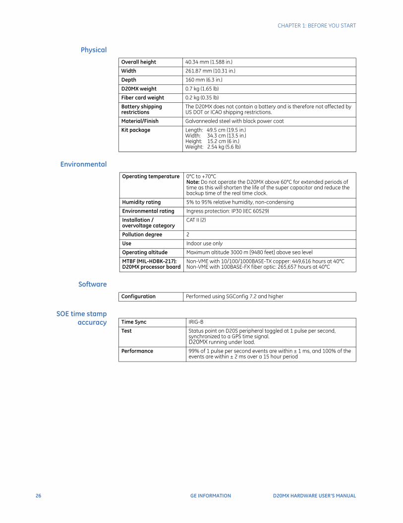
Physical
Environmental
Software
SOE time stamp accuracy
Overall height 40.34 mm (1.588 in.)
Width 261.87 mm (10.31 in.)
Depth 160 mm (6.3 in.)
D20MX weight 0.7 kg (1.65 lb)
Fiber card weight 0.2 kg (0.35 lb)
Battery shipping restrictions
The D20MX does not contain a battery and is therefore not affected by US DOT or ICAO shipping restrictions.
Material/Finish Galvannealed steel with black power coat
Kit package Length: 49.5 cm (19.5 in.)Width: 34.3 cm (13.5 in.)Height: 15.2 cm (6 in.)Weight: 2.54 kg (5.6 lb)
Operating temperature 0°C to +70°CNote: Do not operate the D20MX above 60°C for extended periods of time as this will shorten the life of the super capacitor and reduce the backup time of the real time clock.
Humidity rating 5% to 95% relative humidity, non-condensing
Environmental rating Ingress protection: IP30 (IEC 60529)
Installation /overvoltage category
CAT II (2)
Pollution degree 2
Use Indoor use only
Operating altitude Maximum altitude 3000 m [9480 feet] above sea level
MTBF (MIL-HDBK-217): D20MX processor board
Non-VME with 10/100/1000BASE-TX copper: 449,616 hours at 40°CNon-VME with 100BASE-FX fiber optic: 265,657 hours at 40°C
Configuration Performed using SGConfig 7.2 and higher
Time Sync IRIG-B
Test Status point on D20S peripheral toggled at 1 pulse per second, synchronized to a GPS time signal.D20MX running under load.
Performance 99% of 1 pulse per second events are within ± 1 ms, and 100% of the events are within ± 2 ms over a 15 hour period
CHAPTER 1: BEFORE YOU START
D20MX HARDWARE USER’S MANUAL GE INFORMATION 27
Storage recommendations
Storage conditions Always store the D20MX in an environment compatible with operating conditions. Recommended environmental conditions for storage are:
• Temperature: -40 °C to +85 °C
• Relative humidity: 5% to 95%, non-condensing
• Maximum altitude: 12192 m [40,000 feet] above sea level
NOTE
Do not store the D20MX above 60°C for extended periods of time as this will shorten the life of the super capacitor and reduce the backup time of the real time clock.
When powered off, the D20MX real time clock will remain active for 14 days at -40°C to 60°C, and greater than one month at 25°C. Information in the NVRAM will remain stored indefinitely as flash memory is used.

28 GE INFORMATION D20MX HARDWARE USER’S MANUAL
CHAPTER 1: BEFORE YOU START
D20MX HARDWARE USER’S MANUAL GE INFORMATION 29
D20MX Processor
Chapter 2: Installing the D20MX
Installing the D20MX
This chapter covers the following topics:
• D20 chassis layouts
• Overview of the steps and tools required to install the D20MX
• Retrofitting the D20MX in an existing D20
• Grounding the D20MX and connecting the power supply
D20 chassis layouts
Installation of the D20MX can be performed with one of three D20 chassis layouts; see “Installation steps” on page 31.The D20 non-VME chassis front panel layouts for the D20MX upgrade kits comprise:
• A D20 containing a D20MX with front Ethernet connectors; see Figure 6.
• A D20 containing a D20MX with front Fiber Optic connectors; see Figure 7.
• A D20 containing a D20MX with rear Fiber Optic connectors; see Figure 8.

30 GE INFORMATION D20MX HARDWARE USER’S MANUAL
CHAPTER 2: INSTALLING THE D20MX
Figure 6: D20 chassis front panel - D20MX with Ethernet connectors
Figure 7: D20 chassis front panel - D20MX with front fiber optic connectors
D20 chassis
D20 power supply
D20MX processor
D20MX cover plate
D20MX cover plate filler
Protective earth terminal
D20 chassis
D20 power supply
D20MX processor
D20MX cover plate
D20MX cover plate filler
Protective earth terminal
CHAPTER 2: INSTALLING THE D20MX
D20MX HARDWARE USER’S MANUAL GE INFORMATION 31
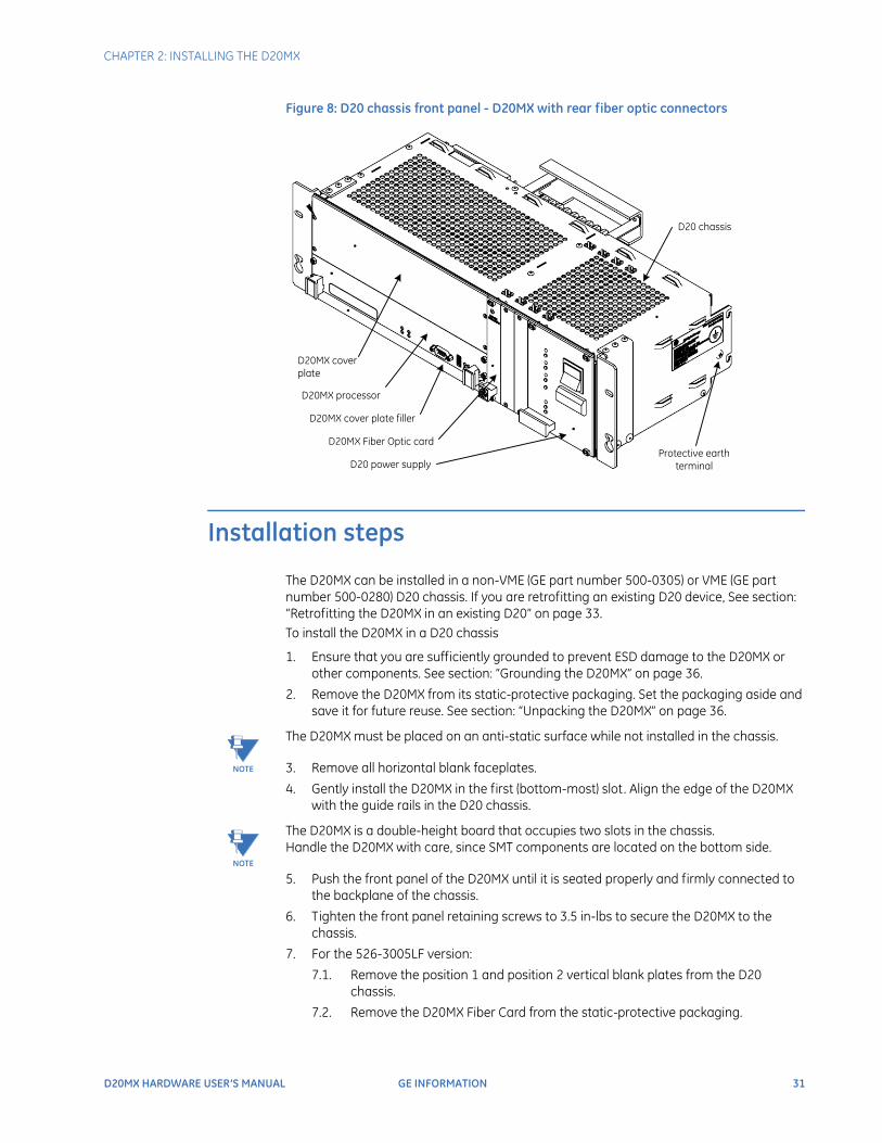
Figure 8: D20 chassis front panel - D20MX with rear fiber optic connectors
Installation steps
The D20MX can be installed in a non-VME (GE part number 500-0305) or VME (GE part number 500-0280) D20 chassis. If you are retrofitting an existing D20 device, See section: “Retrofitting the D20MX in an existing D20” on page 33. To install the D20MX in a D20 chassis
1. Ensure that you are sufficiently grounded to prevent ESD damage to the D20MX or other components. See section: “Grounding the D20MX” on page 36.
2. Remove the D20MX from its static-protective packaging. Set the packaging aside and save it for future reuse. See section: “Unpacking the D20MX” on page 36.
NOTE
The D20MX must be placed on an anti-static surface while not installed in the chassis.
3. Remove all horizontal blank faceplates.
4. Gently install the D20MX in the first (bottom-most) slot. Align the edge of the D20MX with the guide rails in the D20 chassis.
NOTE
The D20MX is a double-height board that occupies two slots in the chassis.Handle the D20MX with care, since SMT components are located on the bottom side.
5. Push the front panel of the D20MX until it is seated properly and firmly connected to the backplane of the chassis.
6. Tighten the front panel retaining screws to 3.5 in-lbs to secure the D20MX to the chassis.
7. For the 526-3005LF version:
7.1. Remove the position 1 and position 2 vertical blank plates from the D20 chassis.
7.2. Remove the D20MX Fiber Card from the static-protective packaging.
D20 chassis
D20 power supply
D20MX processor
D20MX cover plate
D20MX cover plate filler
D20MX Fiber Optic cardProtective earth
terminal

32 GE INFORMATION D20MX HARDWARE USER’S MANUAL
CHAPTER 2: INSTALLING THE D20MX
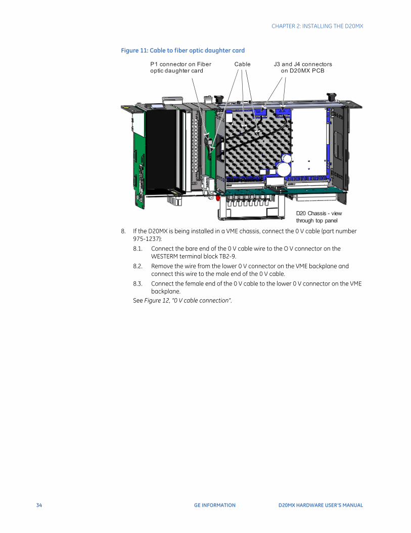
7.3. Connect the 20-pin header end of the cable (part number 975-1236) to connector P1 on the fiber optic daughter card.
7.4. Secure the cable to the fiber optic daughter card with a cable tie.
7.5. Insert the fiber optic daughter card partially into the chassis, and feed the other ends of the cable through the middle slot in the chassis wall between the VME slots and the peripheral slots.
7.6. Connect the other end of the cable (with two connectors) to the D20MX connectors J3 (shorter length of cable) and J4 (longer length of cable).See Figure 11, “Cable to fiber optic daughter card,” on page 34. Ensure that the cable is not pinched.
7.7. Push the front panel of the fiber optic daughter card until it is fully inserted.
7.8. Tighten the front panel retaining screws to 3.5 in-lbs to secure the fiber optic daughter card to the chassis.
8. Install the new lower filler plate (part number 953-1015).
9. Install the new filler plate (part number 953-1014) in the space above the D20MX.
10. Attach any required communication cables to the connectors on the front panel of the D20MX or the backplane of the D20 chassis.
11. If the D20MX is being installed in a VME chassis, connect the 0 V cable (part number 975-1237):
11.1. Connect the bare end of the cable wire to the O V connector on the WESTERM terminal block TB2-9.
11.2. Remove the wire from the lower 0 V connector on the VME backplane and connect this wire to the male end of the 0 V cable.
11.3. Connect the female end of the 0 V cable to the lower 0 V connector on the VME backplane.
See Figure 12, “0 V cable connection”.
12. Install the ferrite clamp if necessary.If you ordered a complete D20 system including the D20MX, notice that a ferrite clamp has already been attached to the power cable. Go to step 13.If you ordered a D20MX upgrade kit, a ferrite clamp included in the package is to be attached to the power inlet cable:
12.1. Ensure that you are sufficiently grounded to prevent ESD damage to the D20MX or other components. See “Grounding the D20MX” on page 36..
12.2. Remove ferrite clamp (GE part number 460-0073) from the package; handle with care as the magnetic material is fragile.
12.3. Pass the power cable through the channel, approximately 15 cm (6 inches) from the connector on the chassis.
12.4. Loop the power cable one more time around and through the core. See Figure 9.
Figure 9: Open ferrite clamp
CHAPTER 2: INSTALLING THE D20MX
D20MX HARDWARE USER’S MANUAL GE INFORMATION 33
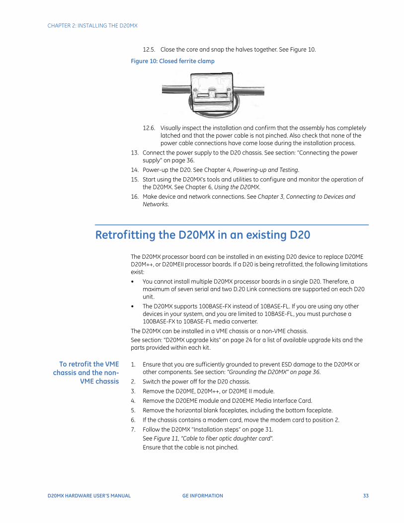
12.5. Close the core and snap the halves together. See Figure 10.
Figure 10: Closed ferrite clamp
12.6. Visually inspect the installation and confirm that the assembly has completely latched and that the power cable is not pinched. Also check that none of the power cable connections have come loose during the installation process.
13. Connect the power supply to the D20 chassis. See section: “Connecting the power supply” on page 36.
14. Power-up the D20. See Chapter 4, Powering-up and Testing.
15. Start using the D20MX’s tools and utilities to configure and monitor the operation of the D20MX. See Chapter 6, Using the D20MX.
16. Make device and network connections. See Chapter 3, Connecting to Devices and Networks.
Retrofitting the D20MX in an existing D20
The D20MX processor board can be installed in an existing D20 device to replace D20ME D20M++, or D20MEII processor boards. If a D20 is being retrofitted, the following limitations exist:
• You cannot install multiple D20MX processor boards in a single D20. Therefore, a maximum of seven serial and two D.20 Link connections are supported on each D20 unit.
• The D20MX supports 100BASE-FX instead of 10BASE-FL. If you are using any other devices in your system, and you are limited to 10BASE-FL, you must purchase a 100BASE-FX to 10BASE-FL media converter.
The D20MX can be installed in a VME chassis or a non-VME chassis.See section: “D20MX upgrade kits” on page 24 for a list of available upgrade kits and the parts provided within each kit.
To retrofit the VME chassis and the non-
VME chassis
1. Ensure that you are sufficiently grounded to prevent ESD damage to the D20MX or other components. See section: “Grounding the D20MX” on page 36.
2. Switch the power off for the D20 chassis.
3. Remove the D20ME, D20M++, or D20ME II module.
4. Remove the D20EME module and D20EME Media Interface Card.
5. Remove the horizontal blank faceplates, including the bottom faceplate.
6. If the chassis contains a modem card, move the modem card to position 2.
7. Follow the D20MX “Installation steps” on page 31.See Figure 11, “Cable to fiber optic daughter card”.Ensure that the cable is not pinched.
34 GE INFORMATION D20MX HARDWARE USER’S MANUAL
CHAPTER 2: INSTALLING THE D20MX
Figure 11: Cable to fiber optic daughter card
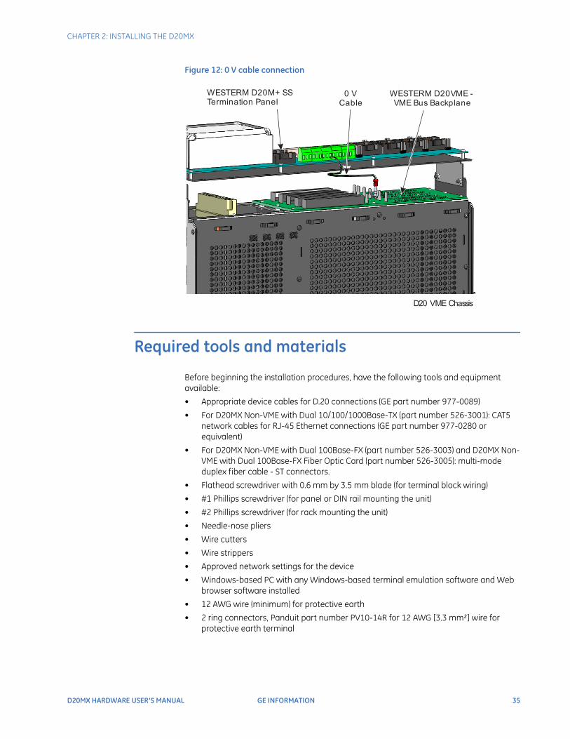
8. If the D20MX is being installed in a VME chassis, connect the 0 V cable (part number 975-1237):
8.1. Connect the bare end of the 0 V cable wire to the O V connector on the WESTERM terminal block TB2-9.
8.2. Remove the wire from the lower 0 V connector on the VME backplane and connect this wire to the male end of the 0 V cable.
8.3. Connect the female end of the 0 V cable to the lower 0 V connector on the VME backplane.
See Figure 12, “0 V cable connection”.
P1 connector on Fiber optic daughter card
J3 and J4 connectors on D20MX PCB
Cable
D20 Chassis - view through top panel
CHAPTER 2: INSTALLING THE D20MX
D20MX HARDWARE USER’S MANUAL GE INFORMATION 35
Figure 12: 0 V cable connection
Required tools and materials
Before beginning the installation procedures, have the following tools and equipment available:
• Appropriate device cables for D.20 connections (GE part number 977-0089)
• For D20MX Non-VME with Dual 10/100/1000Base-TX (part number 526-3001): CAT5 network cables for RJ-45 Ethernet connections (GE part number 977-0280 or equivalent)
• For D20MX Non-VME with Dual 100Base-FX (part number 526-3003) and D20MX Non-VME with Dual 100Base-FX Fiber Optic Card (part number 526-3005): multi-mode duplex fiber cable - ST connectors.
• Flathead screwdriver with 0.6 mm by 3.5 mm blade (for terminal block wiring)
• #1 Phillips screwdriver (for panel or DIN rail mounting the unit)
• #2 Phillips screwdriver (for rack mounting the unit)
• Needle-nose pliers
• Wire cutters
• Wire strippers
• Approved network settings for the device
• Windows-based PC with any Windows-based terminal emulation software and Web browser software installed
• 12 AWG wire (minimum) for protective earth
• 2 ring connectors, Panduit part number PV10-14R for 12 AWG [3.3 mm²] wire for protective earth terminal
WESTERM D20M+ SS Termination Panel
D20 VME Chassis
WESTERM D20VME - VME Bus Backplane
0 V Cable
36 GE INFORMATION D20MX HARDWARE USER’S MANUAL
CHAPTER 2: INSTALLING THE D20MX
Grounding the D20MX
Surge and noise suppression components used on the D20MX are designed to prevent nuisance operation and damage to internal components. To ensure correct protective operation, the earth ground wire (14AWG green wire) on the D20 chassis must be connected to a low impedance ground rail of a secondary cabinet or rack.When making ground connections, ensure that all surfaces that are used for grounding are free of dirt, residue and corrosion.
Do not power up the D20 before establishing a proper protective earth connection.
Unpacking the D20MX
Carefully remove the D20MX from its packaging. Visually inspect the unit to ensure it has not sustained any visible damage during transit. If there are visible signs of damage, report it immediately to the carrier.
Package contentsThe following items are provided as part of your D20MX shipment:
• D20MX unit (GE part number 526-3001, or 526-3003, or 526-3005)
• For 526-3005LF only:
– D20MX to Fiber Card Harness (975-1236)
– D20MX 100BASE-FX Rear LC FO Card (part number 526-3103LF) or D20MX 100BASE-FX Rear ST FO Card (part number 526-3104LF)
• Lower filler plate (part number 953-1015)
• Blank plate for D20MX install (part number 953-1014)
• 0 V wire cable (part number 975-1237)
• For 526-3005LF installed in 500-0280 only:
– Termination Panel, D20MX extended mounting (952-2087)
• GE Digital Energy Product Documentation CD (GE part number 581-0002)
• GE Digital Energy D20MX Documentation CD (GE part number 588-0075)
• SGConfig Tool CD providing device configuration software (GE part number 588-0082)
Verify that you have received all items. GE parts include a unique number, typically in the format XXX-XXXX, that can be used as a reference.
Connecting the power supply
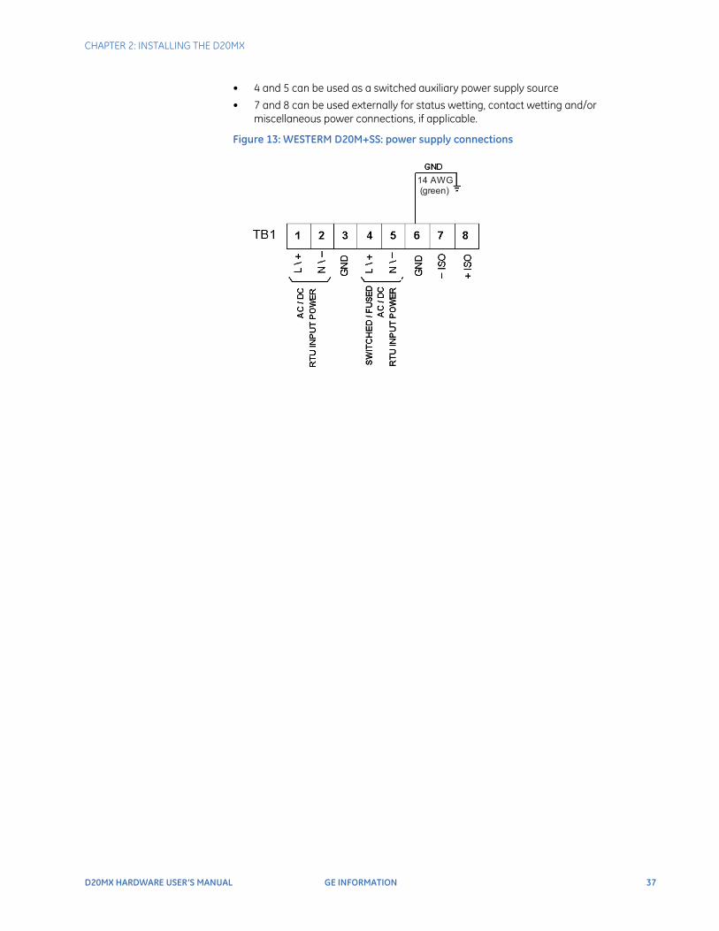
The D20MX processor board is supplied power through the WESTERM D20M+ SS backplane. Power connections to the backplane are made on connector block TB1.For the WESTERM D20M+ SS and WESTERM D20M+ (see Figure 13, “WESTERM D20M+SS: power supply connections”) the power supply connections:
• 1 and 2 are used for input power connections based on the D20 power supply
CHAPTER 2: INSTALLING THE D20MX
D20MX HARDWARE USER’S MANUAL GE INFORMATION 37
• 4 and 5 can be used as a switched auxiliary power supply source
• 7 and 8 can be used externally for status wetting, contact wetting and/or miscellaneous power connections, if applicable.
Figure 13: WESTERM D20M+SS: power supply connections
14 AWG (green)

38 GE INFORMATION D20MX HARDWARE USER’S MANUAL
CHAPTER 2: INSTALLING THE D20MX
D20MX HARDWARE USER’S MANUAL GE INFORMATION 39
D20MX Processor
Chapter 3: Connecting to Devices and Networks
Connecting to Devices and Networks
This chapter provides guidelines for making physical connections between the D20 and substation and network devices.
Cabling overview
All physical connections are made to the connectors on the rear backplane of the D20 chassis or to the front on the D20MX processor module.
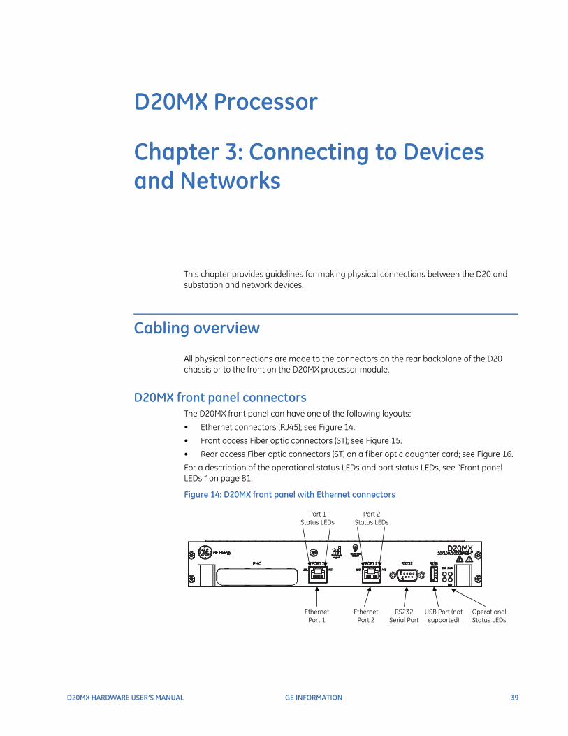
D20MX front panel connectorsThe D20MX front panel can have one of the following layouts:
• Ethernet connectors (RJ45); see Figure 14.
• Front access Fiber optic connectors (ST); see Figure 15.
• Rear access Fiber optic connectors (ST) on a fiber optic daughter card; see Figure 16.
For a description of the operational status LEDs and port status LEDs, see “Front panel LEDs ” on page 81.
Figure 14: D20MX front panel with Ethernet connectors
Ethernet Port 1
Ethernet Port 2
RS232 Serial Port
Operational Status LEDs
USB Port (not supported)
Port 1 Status LEDs
Port 2 Status LEDs
40 GE INFORMATION D20MX HARDWARE USER’S MANUAL
CHAPTER 3: CONNECTING TO DEVICES AND NETWORKS
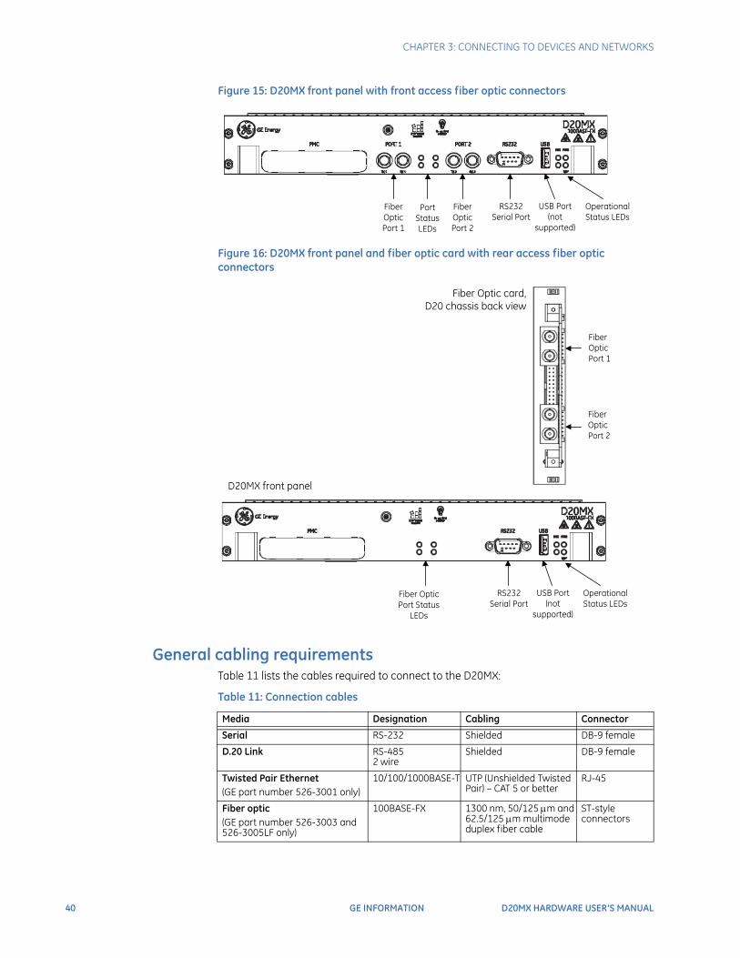
Figure 15: D20MX front panel with front access fiber optic connectors
Figure 16: D20MX front panel and fiber optic card with rear access fiber optic connectors
General cabling requirementsTable 11 lists the cables required to connect to the D20MX:
Table 11: Connection cables
Fiber Optic Port 1
Fiber Optic Port 2
RS232 Serial Port
Operational Status LEDs
USB Port(not
supported)
Port Status LEDs
Fiber Optic Port 2
Fiber Optic Port 1
RS232 Serial Port
Operational Status LEDs
USB Port(not
supported)
Fiber Optic Port Status
LEDs
Fiber Optic card, D20 chassis back view
D20MX front panel
Media Designation Cabling Connector
Serial RS-232 Shielded DB-9 female
D.20 Link RS-4852 wire
Shielded DB-9 female
Twisted Pair Ethernet(GE part number 526-3001 only)
10/100/1000BASE-T UTP (Unshielded Twisted Pair) – CAT 5 or better
RJ-45
Fiber optic(GE part number 526-3003 and 526-3005LF only)
100BASE-FX 1300 nm, 50/125 m and 62.5/125 m multimode duplex fiber cable
ST-style connectors
CHAPTER 3: CONNECTING TO DEVICES AND NETWORKS
D20MX HARDWARE USER’S MANUAL GE INFORMATION 41
To provide higher EMC immunity and maintain CE Mark radiated emission compliance, the serial cables used for permanent serial and D.20 Link connections must comply with the following requirements:
• Cables must be shielded
• D-type connector covers must provide EMC shielding (e.g. metallized plastic or die cast metal covers).
Serial
Seven serial communications ports are brought out to the backplane connector P2. These serial ports are five-signal (TXD, RXD, RTS#, CTS#, DCD#) DTE serial ports, compliant to ANSI/TIA-232 and TIA/EIA-694 specifications and are hosted by UARTs.The D20MX is tested with all 7 serial ports running at 19200 baud with 20% CPU utilization. Refer to application configuration guides for supported baud rates and for data bits.
To avoid burning out the WESTERM or D20MX mainboard when directly connecting a rear-panel serial port on one D20MX chassis to another rear-panel serial port on any type of D20 chassis, jumper the WESTERM of both chassis' to not provide a power connection to pin 4. Refer to the appropriate WESTERM module layout for jumper settings.
D.20 Link
Communications between the D20 and the D20 peripheral I/O modules are carried over a high-speed, high-level data link control (HDLC) protocol called the D.20 Link. The D.20 Link has the following features:
• RS-485 serial link, half duplex, 250 kbps
• D.20 frame using HDLC protocol format with Manchester encoding
• Supports up to 31 D20 I/O peripheral modules in a standard configuration
• Repeater/extension modules (GE part number 520-0148) may be used to extend this limit to a maximum of 120 peripheral modules. The D20MX is compatible only with certain peripheral common code (i.e., pcommon) versions as defined in Table 12.
Table 12: PCOMMON versions compatible with the D20MX
PCOMMON Description Versions compatible with the D20MX
P022 - PCOMMON for D20C 3.0x
P010 - PCOMMON for D20A, D20S and D20K 3.0x
P087 - pBOOT for D20AC 104
42 GE INFORMATION D20MX HARDWARE USER’S MANUAL
CHAPTER 3: CONNECTING TO DEVICES AND NETWORKS
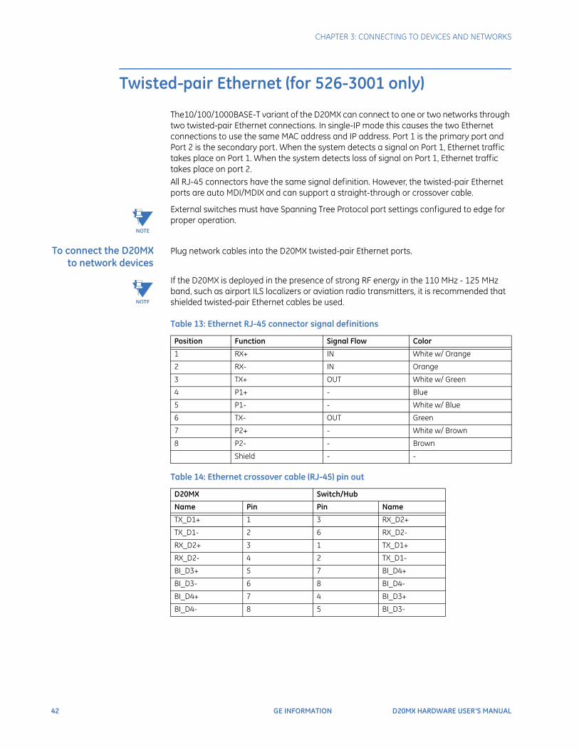
Twisted-pair Ethernet (for 526-3001 only)
The10/100/1000BASE-T variant of the D20MX can connect to one or two networks through two twisted-pair Ethernet connections. In single-IP mode this causes the two Ethernet connections to use the same MAC address and IP address. Port 1 is the primary port and Port 2 is the secondary port. When the system detects a signal on Port 1, Ethernet traffic takes place on Port 1. When the system detects loss of signal on Port 1, Ethernet traffic takes place on port 2.All RJ-45 connectors have the same signal definition. However, the twisted-pair Ethernet ports are auto MDI/MDIX and can support a straight-through or crossover cable.
NOTE
External switches must have Spanning Tree Protocol port settings configured to edge for proper operation.
To connect the D20MX to network devices
Plug network cables into the D20MX twisted-pair Ethernet ports.
NOTE
If the D20MX is deployed in the presence of strong RF energy in the 110 MHz - 125 MHz band, such as airport ILS localizers or aviation radio transmitters, it is recommended that shielded twisted-pair Ethernet cables be used.
Table 13: Ethernet RJ-45 connector signal definitions
Table 14: Ethernet crossover cable (RJ-45) pin out
Position Function Signal Flow Color
1 RX+ IN White w/ Orange
2 RX- IN Orange
3 TX+ OUT White w/ Green
4 P1+ - Blue
5 P1- - White w/ Blue
6 TX- OUT Green
7 P2+ - White w/ Brown
8 P2- - Brown
Shield - -
D20MX Switch/Hub
Name Pin Pin Name
TX_D1+ 1 3 RX_D2+
TX_D1- 2 6 RX_D2-
RX_D2+ 3 1 TX_D1+
RX_D2- 4 2 TX_D1-
BI_D3+ 5 7 BI_D4+
BI_D3- 6 8 BI_D4-
BI_D4+ 7 4 BI_D3+
BI_D4- 8 5 BI_D3-
CHAPTER 3: CONNECTING TO DEVICES AND NETWORKS
D20MX HARDWARE USER’S MANUAL GE INFORMATION 43
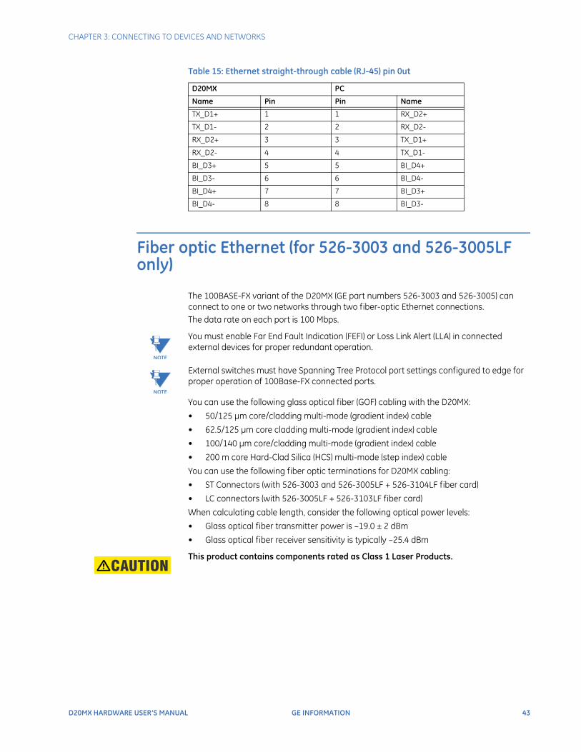
Table 15: Ethernet straight-through cable (RJ-45) pin 0ut
Fiber optic Ethernet (for 526-3003 and 526-3005LF only)
The 100BASE-FX variant of the D20MX (GE part numbers 526-3003 and 526-3005) can connect to one or two networks through two fiber-optic Ethernet connections. The data rate on each port is 100 Mbps.
NOTE
You must enable Far End Fault Indication (FEFI) or Loss Link Alert (LLA) in connected external devices for proper redundant operation.
NOTE
External switches must have Spanning Tree Protocol port settings configured to edge for proper operation of 100Base-FX connected ports.
You can use the following glass optical fiber (GOF) cabling with the D20MX:
• 50/125 μm core/cladding multi-mode (gradient index) cable
• 62.5/125 μm core cladding multi-mode (gradient index) cable
• 100/140 μm core/cladding multi-mode (gradient index) cable
• 200 m core Hard-Clad Silica (HCS) multi-mode (step index) cable
You can use the following fiber optic terminations for D20MX cabling:
• ST Connectors (with 526-3003 and 526-3005LF + 526-3104LF fiber card)
• LC connectors (with 526-3005LF + 526-3103LF fiber card)
When calculating cable length, consider the following optical power levels:
• Glass optical fiber transmitter power is –19.0 ± 2 dBm
• Glass optical fiber receiver sensitivity is typically –25.4 dBm
This product contains components rated as Class 1 Laser Products.
D20MX PC
Name Pin Pin Name
TX_D1+ 1 1 RX_D2+
TX_D1- 2 2 RX_D2-
RX_D2+ 3 3 TX_D1+
RX_D2- 4 4 TX_D1-
BI_D3+ 5 5 BI_D4+
BI_D3- 6 6 BI_D4-
BI_D4+ 7 7 BI_D3+
BI_D4- 8 8 BI_D3-
44 GE INFORMATION D20MX HARDWARE USER’S MANUAL
CHAPTER 3: CONNECTING TO DEVICES AND NETWORKS
LAN redundancy
Both twisted-pair and fiber optic Ethernet options provide two LAN redundancy schemes called single-IP redundancy and dual-IP redundancy.Single-IP redundancy provides automated fail over between two Ethernet network connections (TX1/RX1 and TX2/RX2) that share a single MAC and IP address.When the primary port (that is, port 1) receives no signal, or detects a fault signal from the remote link partner, the D20MX switches to the secondary port (that is, port 2) if it has a valid link. The D20MX reverts to the primary port if the primary link is restored or no signal is present on the secondary port. With dual-IP redundancy, each port has a unique MAC, IP address and subnet. Each remote device participating in dual-IP redundancy must have a primary IP address reachable through the subnet of port 1 of the D20MX and a secondary IP address reachable through the subnet of port 2 of the D20MX. D20MX client applications will fail over to the remote device's secondary IP address when they detect a failure to communicate with the remote device's primary IP address. D20MX server applications accept communications from the remote device's primary or secondary IP address. To configure a system for single-IP redundancy, enable only LAN A in the device properties of the D20MX. To configure a system for dual-IP redundancy, enable both LAN A and LAN B in the device properties of the D20MX. The D20MX device properties may be configured through SGConfig 7.2 and higher.
IP addresses
The D20MX assigns IP configuration to its LAN A and optionally LAN B interface according to the rules defined in Table 16. In a standalone system, the D20MX assigns the LAN A and LAN B IP addresses exactly as you configured them in SGConfig. In a redundant system, the D20MX assigns the LAN A and LAN B IP addresses of the Active CCU exactly as you configured them in SGConfig. However, in other modes, the CCU assigns derived IP addresses as indicated in Table 16. For a description of the modes, refer to Table 18. The D20MX assigns the subnet mask of the derived IP addresses as the subnet mask configured in the LAN A or LAN B configuration.
Table 16: D20MX IP address assignment
CCU Redundant System
Mode LAN A IP Configuration LAN B IP Configuration (If Configured)
CCU A Standalone Active, Debug or Disabled
IP Address: LAN A IP AddressMask: LAN B Subnet Mask (e.g 192.168.1.1 / 255.255.255.0)
IP Address: LAN B IP Address Mask: Configured LAN B Subnet Mask (e.g. 192.168.2.1 / 255.255.255.0)
CCU A Redundant Active
CCU B Redundant Active
CCU A Redundant Standby, Debug or Disabled.
Derived IP Address: LAN A IP Address + 1 Mask: LAN A subnet mask (e.g. 192.168.1.2 / 255.255.255.0)
Derived IP Address: LAN B IP Address + 1 Mask: LAN B subnet mask (e.g. 192.168.2.2 / 255.255.255.0)
CHAPTER 3: CONNECTING TO DEVICES AND NETWORKS
D20MX HARDWARE USER’S MANUAL GE INFORMATION 45
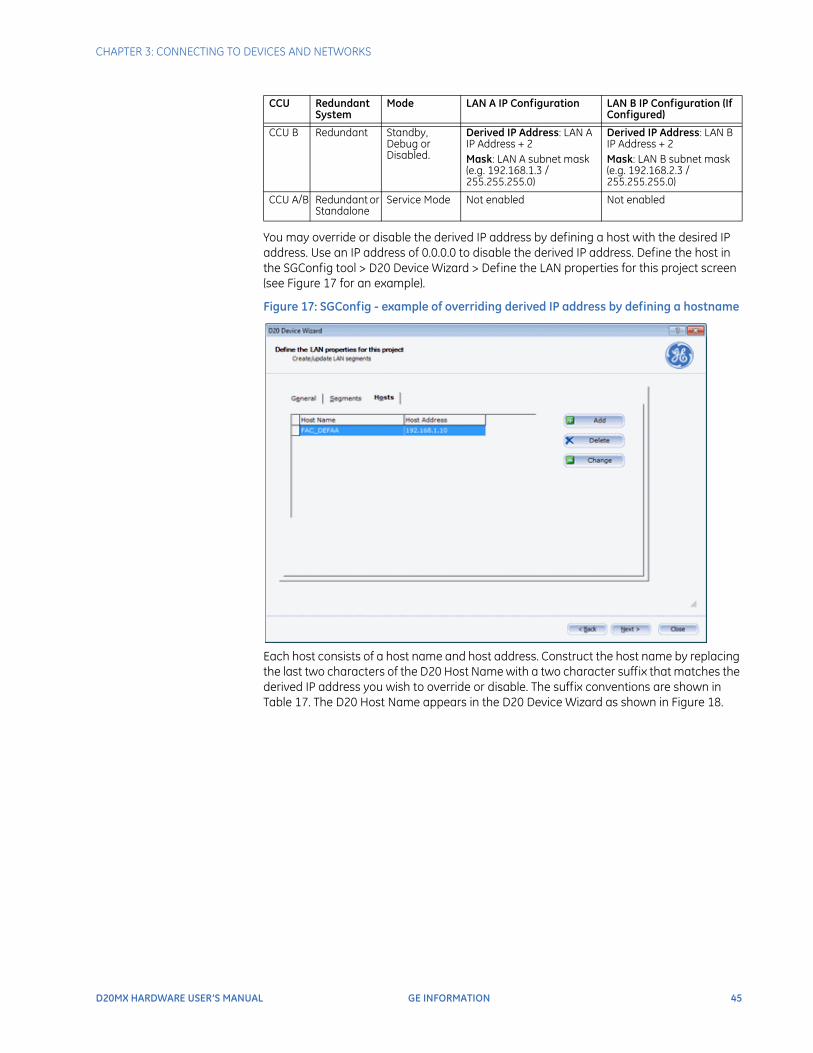
You may override or disable the derived IP address by defining a host with the desired IP address. Use an IP address of 0.0.0.0 to disable the derived IP address. Define the host in the SGConfig tool > D20 Device Wizard > Define the LAN properties for this project screen (see Figure 17 for an example).
Figure 17: SGConfig - example of overriding derived IP address by defining a hostname
Each host consists of a host name and host address. Construct the host name by replacing the last two characters of the D20 Host Name with a two character suffix that matches the derived IP address you wish to override or disable. The suffix conventions are shown in Table 17. The D20 Host Name appears in the D20 Device Wizard as shown in Figure 18.
CCU B Redundant Standby, Debug or Disabled.
Derived IP Address: LAN A IP Address + 2 Mask: LAN A subnet mask (e.g. 192.168.1.3 / 255.255.255.0)
Derived IP Address: LAN B IP Address + 2 Mask: LAN B subnet mask (e.g. 192.168.2.3 / 255.255.255.0)
CCU A/B Redundant or Standalone
Service Mode Not enabled Not enabled
CCU Redundant System
Mode LAN A IP Configuration LAN B IP Configuration (If Configured)
46 GE INFORMATION D20MX HARDWARE USER’S MANUAL
CHAPTER 3: CONNECTING TO DEVICES AND NETWORKS
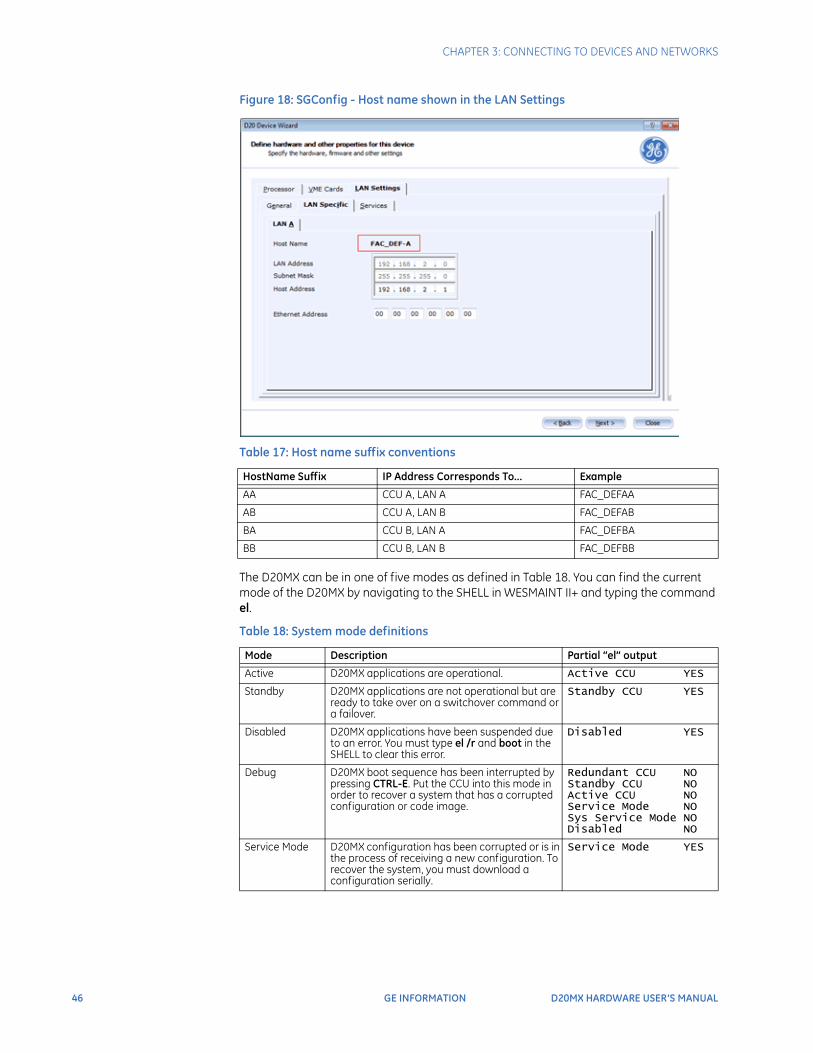
Figure 18: SGConfig - Host name shown in the LAN Settings
Table 17: Host name suffix conventions
The D20MX can be in one of five modes as defined in Table 18. You can find the current mode of the D20MX by navigating to the SHELL in WESMAINT II+ and typing the command el.
Table 18: System mode definitions
HostName Suffix IP Address Corresponds To... Example
AA CCU A, LAN A FAC_DEFAA
AB CCU A, LAN B FAC_DEFAB
BA CCU B, LAN A FAC_DEFBA
BB CCU B, LAN B FAC_DEFBB
Mode Description Partial “el” output
Active D20MX applications are operational. Active CCU YES
Standby D20MX applications are not operational but are ready to take over on a switchover command or a failover.
Standby CCU YES
Disabled D20MX applications have been suspended due to an error. You must type el /r and boot in the SHELL to clear this error.
Disabled YES
Debug D20MX boot sequence has been interrupted by pressing CTRL-E. Put the CCU into this mode in order to recover a system that has a corrupted configuration or code image.
Redundant CCU NO Standby CCU NO Active CCU NO Service Mode NO Sys Service Mode NO Disabled NO
Service Mode D20MX configuration has been corrupted or is in the process of receiving a new configuration. To recover the system, you must download a configuration serially.
Service Mode YES
CHAPTER 3: CONNECTING TO DEVICES AND NETWORKS
D20MX HARDWARE USER’S MANUAL GE INFORMATION 47
RS-232
The RS-232 port on the D20MX is used to access the WESMAINT II+ facility and to transfer code and configuration data to the D20MX. You can use a VT100-compatible terminal or terminal emulation program to directly access the WESMAINT II+ facility. SGConfig's Terminal Emulator is an example of a suitable terminal emulation program.The RS-232 port is connected to the D20MX front panel and is also routed to the rear panel as (COM0). The default baud rate is 19,200.
Non-responsive RS-232 port
In the event that the D20MX RS-232 port appears non-responsive, type Ctrl-Q. This non-responsive condition might occur if your computer goes into sleep mode and then wakes up while still connected to the D20MX RS-232 port.
Use only a NULL modem cable (GE Energy part number 977-0529) when you are connecting to the D20MX front-panel RS-232 connector. Use of a WESMAINT cable will not allow communication to the D20MX.
Use only a standard WESMAINT cable (GE Energy part number 977-0300) when connecting to the rear panel COM0 connector. Use of a NULL modem cable will cause permanent damage to the D20MX and PC.
D20 system redundancy
A redundant D20 setup allows a secondary D20 to automatically take over operations from a paired D20 unit that has failed.D20 equipment redundancy requires:
• Two D20 units and
• One or two RS-232 switch panels.
NOTE
The quiescent current of the +12 V power supply input on the RS-232 Switch Panel is 15 mA. The maximum power requirement on the +12 V input during operation is 230 mA.
Through a toggle switch on the RS-232 Switch Panel, you designate one of the CCUs as the Active unit. If the Active unit hardware or software fails, the Active CCU is automatically switched offline, and the Standby unit is switched through to the field equipment (i.e., it is made Active).The RS-232 Switch Panel is not equipped with EMI protection circuitry. If the connection length exceeds 3m, a Serial Surge Protection Panel (GE item number 540-0249) or equivalent protection device should be installed.Figure 19 shows a redundant D20 system, with CCU A active.

48 GE INFORMATION D20MX HARDWARE USER’S MANUAL
CHAPTER 3: CONNECTING TO DEVICES AND NETWORKS
Figure 19: Redundant D20 system with CCU A active
If the Active CCU fails:
• The Standby CCU detects the failure through the inter-CCU communications link.
• The Standby CCU commands the RS-232 Switch Panel to switch over all serial connections.
• The RS-232 Switch Panel switches all serial field connections to the Standby CCU, which now becomes the Active CCU.
If CCU A fails, CCU B becomes active. See Figure 20, “Redundant D20 system - If CCU A fails”.
Figure 20: Redundant D20 system - If CCU A fails
RS-232 Switch Panel
CCU A(Active)
CCU B(Standby)
CCU B SerialCommunications
CCU A SerialCommunications
To Field Equipment
Inter-CCU Communications
RS-232 Switch Monitor and Control
RS-232 Switch Panel
CCU A(Failed)
CCU B(Active)
CCU B SerialCommunications
CCU A SerialCommunications
To Field Equipment
Inter-CCU Communications
RS-232 Switch Monitor and Control
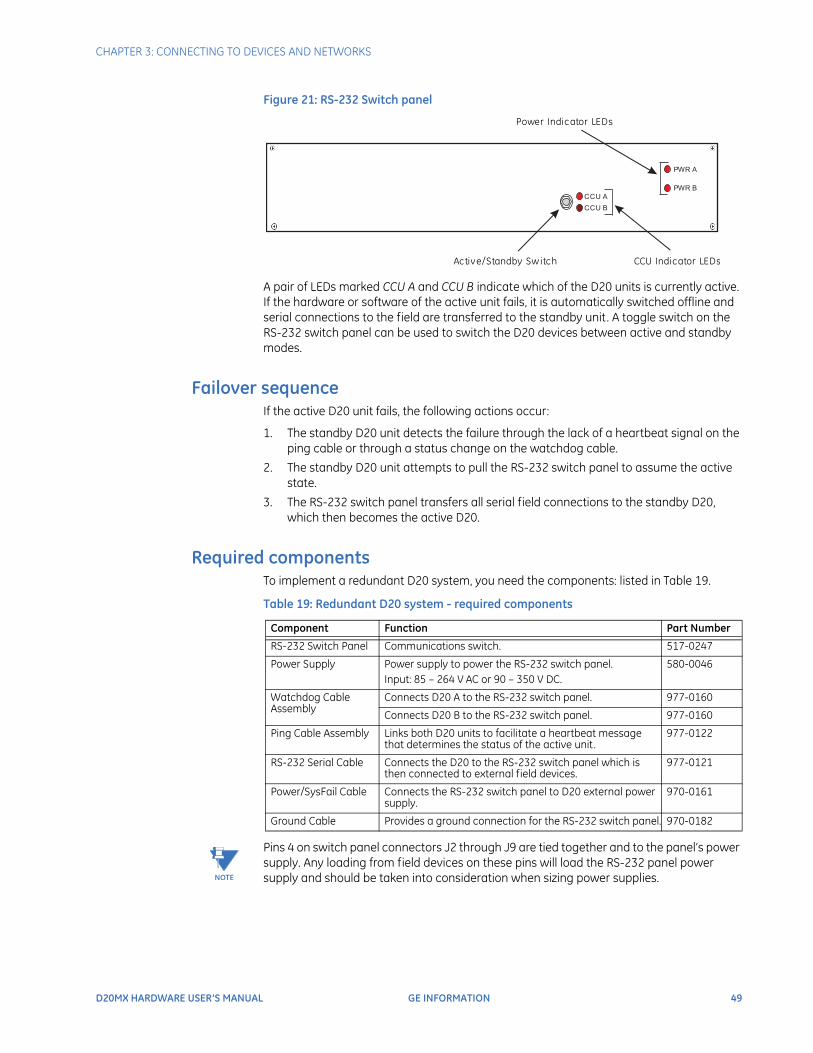
CHAPTER 3: CONNECTING TO DEVICES AND NETWORKS
D20MX HARDWARE USER’S MANUAL GE INFORMATION 49
Figure 21: RS-232 Switch panel
A pair of LEDs marked CCU A and CCU B indicate which of the D20 units is currently active. If the hardware or software of the active unit fails, it is automatically switched offline and serial connections to the field are transferred to the standby unit. A toggle switch on the RS-232 switch panel can be used to switch the D20 devices between active and standby modes.
Failover sequenceIf the active D20 unit fails, the following actions occur:
1. The standby D20 unit detects the failure through the lack of a heartbeat signal on the ping cable or through a status change on the watchdog cable.
2. The standby D20 unit attempts to pull the RS-232 switch panel to assume the active state.
3. The RS-232 switch panel transfers all serial field connections to the standby D20, which then becomes the active D20.
Required componentsTo implement a redundant D20 system, you need the components: listed in Table 19.
Table 19: Redundant D20 system - required components
NOTE
Pins 4 on switch panel connectors J2 through J9 are tied together and to the panel’s power supply. Any loading from field devices on these pins will load the RS-232 panel power supply and should be taken into consideration when sizing power supplies.
Active/Standby Sw itch
Power Indicator LEDs
CCU Indicator LEDs
CCU A
CCU B
PWR A
PWR B
Component Function Part Number
RS-232 Switch Panel Communications switch. 517-0247
Power Supply Power supply to power the RS-232 switch panel.Input: 85 – 264 V AC or 90 – 350 V DC.
580-0046
Watchdog Cable Assembly
Connects D20 A to the RS-232 switch panel. 977-0160
Connects D20 B to the RS-232 switch panel. 977-0160
Ping Cable Assembly Links both D20 units to facilitate a heartbeat message that determines the status of the active unit.
977-0122
RS-232 Serial Cable Connects the D20 to the RS-232 switch panel which is then connected to external field devices.
977-0121
Power/SysFail Cable Connects the RS-232 switch panel to D20 external power supply.
970-0161
Ground Cable Provides a ground connection for the RS-232 switch panel. 970-0182
50 GE INFORMATION D20MX HARDWARE USER’S MANUAL
CHAPTER 3: CONNECTING TO DEVICES AND NETWORKS
To set up a redundant system
It is recommended that you install and configure one standalone D20 unit to ensure that your configuration is valid and that device communications are operating properly. Once this is done, proceed with the installation of the redundant system.
1. Mount the D20 units in a rack and connect power and ground.
2. Mount the RS-232 switch panel.
3. Plug the connector of watchdog cable A (GE part number 977-0160) to serial connector COM 6 on the first D20 (CCU A).
4. Connect the bare leads of watchdog cable A to TB1 (position 6-8) on the RS-232 switch panel.
5. Plug the connector of watchdog cable B (GE part number 977-0160) to serial connector COM 6 on the second D20 (CCU B).
6. Connect the bare leads of watchdog cable B to TB1 (position 14-16) on the RS-232 switch panel.
7. Connect the bare leads of both watchdog cables to TB1 on the RS-232 switch panel and the DB9 serial connector to either P1 or P9.
8. Connect one end of the ping cable to the first D20 and the other end to the second D20. This ping cable must be connected to the same serial port number on both units.
9. Use standard RS-232 cables (GE part number 977-0121) to connect the D20 serial communication ports to the serial ports on the RS-232 switch panel. P1 through P8 are connected to the first D20, P9 through P16 are connected to the second D20. Connections from the switch panel to both D20 units should be made in the same order. For example, if P1 is connected to port 3 on the first D20, P9 should also be connected to port 3 on the second D20.
10. Connect field devices to J1 through J8 on the RS-232 switch panel.
RS-232 switch panel operationThe RS2-32 switch panel has two sets of indicator LEDS:
• PWR A/PWR B: When lit , power and communications are received from the connected units. Normally, both LEDs are lit .
• CCU A/CCU B: Normally, one LED is lit , indicating which unit is active.
The active/standby switch on the front of the RS-232 switch panel is used to:
• Restore a previously failed unit to active status once it has been repaired.
• Manually force a unit to active status so that routine maintenance can be performed on the other unit.
To manually operate the RS-232 switch
panel
1. Pull the active/standby switch straight out to release it from the locked position.
2. Switch it up to make unit A active or down to make unit B active.The CCU A/CCU B LED indicator indicates which unit has been activated.
Redundancy wiring diagramsFigure 22 illustrates how to wire the D20MX units and RS-232 switch panels to enable system redundancy:
NOTE
The D20MX watchdog (control) port, heartbeat (ping) port, and serial port assignments are software configurable. Refer to the D2x Configuration Guides.
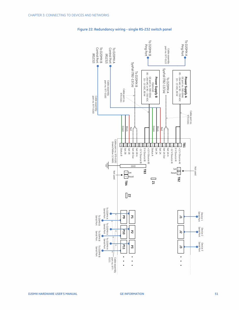
CHAPTER 3: CONNECTING TO DEVICES AND NETWORKS
D20MX HARDWARE USER’S MANUAL GE INFORMATION 51
Figure 22: Redundancy wiring - single RS-232 switch panel

52 GE INFORMATION D20MX HARDWARE USER’S MANUAL
CHAPTER 3: CONNECTING TO DEVICES AND NETWORKS
D20MX HARDWARE USER’S MANUAL GE INFORMATION 53
D20MX Processor
Chapter 4: Powering-up and Testing
Powering-up and Testing
Once you have made all field wiring and communication connections and have completed the necessary hardware configuration, the next step is to power-up the D20MX and verify that it is functioning properly.Use this chapter to prepare for and correctly perform the power-up and other tests. This chapter includes:
• What is needed to test: WESMAINT II+ facility, SHELL and SGConfig
• How to power-up the D20MX and conduct the BOOT Test: Power On Self-Test
• How to carry out a redundant system test
NOTE
Before any of the tests and procedures in this section can be performed, a valid configuration file must be loaded into the D20MX NVRAM. If you have replaced the main board of the D20MX, then you will need to restore the configuration file so that diagnostic tests can be performed.If this power-up and test procedure reveals that your D20MX is not functioning properly due to software malfunction, then you need to download code and configuration files.See the SGConfig online help.
Required for testing
The system components that are required for configuring and testing the D20MX are:
• WESMAINT II+ facility
• SHELL
• SGConfig application
To prevent burning out the main processor board, make two important checks before switching on the D20MX:
• Check that the external power supply input level is correct for the Power Supply fitted to the chassis. See section: “Power supply” on page 21.
• If you have 125 V DC or 110V AC input, then jumpers Z22 and Z23 on the WESTERM D20M+: 517 - 0225 or 517 - 0224 must be jumpered 2 - 3.
54 GE INFORMATION D20MX HARDWARE USER’S MANUAL
CHAPTER 4: POWERING-UP AND TESTING
Accessing WESMAINT II+ using a terminalYou can use a VT100-compatible terminal or a terminal emulation program to directly access the WESMAINT II+ facility. SGConfig's Terminal Emulator is an example of a suitable terminal emulation program.
NOTE
For further information about using WESMAINT II+ software to perform any of the test procedures in this section, refer to the WESMAINT II+ User’s Guide.
Terminal EmulationMicrosoft Windows™ HyperTerminal can be used for terminal emulation but it is NOT recommended because code and configuration file download times are considerably increased.
TIP
The program Tera Term for Microsoft Windows™ does not have these limitations and is therefore recommended as a terminal emulation program. It can be downloaded from the Internet.
SHELLThe SHELL is a debugging and diagnostics tool that is accessible as a menu selection in WESMAINT II+, or from a basic login prompt if WESMAINT II+ is not available.
Power up and test steps
To power up and test the D20MX:
1. “Set up a PC to act as a WESMAINTII+ terminal”. See page 55.
2. “Power up the D20MX” on page 55. See page 55.
Result: The D20MX automatically runs the Online Start-up test. See “Automatic on-line start-up test” on page 55.
3. “Test for redundancy”. See page 56.
4. “Check that fail-over is functioning correctly”. See page 57.
5. “Check that switch-over is functioning correctly”. See page 57.
6. “Verify either hardware or software switch-over”. See page 58.
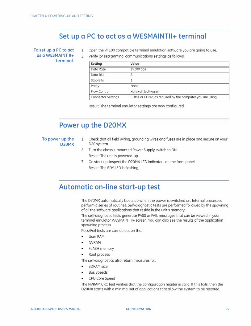
CHAPTER 4: POWERING-UP AND TESTING
D20MX HARDWARE USER’S MANUAL GE INFORMATION 55
Set up a PC to act as a WESMAINTII+ terminal
To set up a PC to act as a WESMAINT II+
terminal.
1. Open the VT100 compatible terminal emulation software you are going to use.
2. Verify (or set) terminal communications settings as follows:
Result: The terminal emulator settings are now configured.
Power up the D20MX
To power up the D20MX
1. Check that all field wiring, grounding wires and fuses are in place and secure on your D20 system.
2. Turn the chassis-mounted Power Supply switch to ON.
Result: The unit is powered-up.
3. On start-up, inspect the D20MX LED indicators on the front panel.
Result: The RDY LED is flashing.
Automatic on-line start-up test
The D20MX automatically boots up when the power is switched on. Internal processes perform a series of routines. Self-diagnostic tests are performed followed by the spawning of all the software applications that reside in the unit's memory.The self-diagnostic tests generate PASS or FAIL messages that can be viewed in your terminal emulator WESMAINT II+ screen. You can also see the results of the application spawning process.Pass/Fail tests are carried out on the:
• User RAM
• NVRAM
• FLASH memory
• Root process
The self-diagnostics also return measures for:
• SDRAM size
• Bus Speeds
• CPU Core Speed
The NVRAM CRC test verifies that the configuration header is valid. If this fails, then the D20MX starts with a minimal set of applications that allow the system to be restored.
Setting Value
Data Rate 19200 bps
Data Bits 8
Stop Bits 1
Parity None
Flow Control Xon/Xoff (software)
Connector Settings COM1 or COM2, as required by the computer you are using
56 GE INFORMATION D20MX HARDWARE USER’S MANUAL
CHAPTER 4: POWERING-UP AND TESTING
Code and configuration filesIf the code and configuration files compiled for your specific system are already downloaded, then you can login straightaway to WESMAINT II+ for powering-up and testing.If your system-specific code and configuration files are not downloaded, then you need to power-up with the default configuration. You can then login to the SHELL, download your system-specific files and restart the D20MX for testing.For details, see the SGConfig online help.
Further testingFor further specific testing, log in to WESMAINT II+. See the WESMAINT II+ Users Guide and WESMAINT user guides for specific applications.
Test for redundancy
If you have a D20 redundant system, you must test that:
• CCU A and CCU B are communicating
• Fail-over is functioning correctly.
To check that CCU A and CCU B are communicating once you have powered-up the Primary and Secondary units:
1. On the front of the RS-232 Panel, check that CCU A LED is illuminated, which shows that CCU A is Active.
NOTE
Both the PWR A and PWR B LEDs should be illuminated.
2. Connect a NULL modem cable (GE Energy part number 977-0529) to the RS-232 connector on the front panel of the active D20MX.
3. Attach the other end of the cable to the serial communications port of the PC or terminal.
4. Login to WESMAINT II+ through the emulator you are using.
Result: The WESMAINT Main Menu is displayed.
5. Check to see that STNBY appears at the top-left of this WESMAINT screen.
Results: If this text shows, then the Primary and Secondary CCU are communicating.
If this text does not show, then the Primary and Secondary are not communicating.
NOTE
STNBY appears on the Active CCU WESMAINT Main Menu display approximately one minute after power-up of the two units. Wait for this message to appear before following the next procedure.
CHAPTER 4: POWERING-UP AND TESTING
D20MX HARDWARE USER’S MANUAL GE INFORMATION 57
Check that fail-over is functioning correctly
To check that fail-over is functioning correctly for the event of hardware failure:
1. On the front of the RS-232 Panel, check that CCU A LED is illuminated, which shows that CCU A is Active.
NOTE
Both the PWR A and PWR B LEDs should be illuminated.
2. To simulate hardware failure, switch off the Active D20MX at the main power switch on the front of the unit.
Result: If the RS-232 is functioning correctly, then it will switch over to the Standby unit and the CCU B LED will illuminate and the CCU A LED will go off.
Check that switch-over is functioning correctly
To check that switch-over is functioning correctly for the event of software failure:
1. On the front of the RS-232 Panel, check that CCU A LED is illuminated, which shows that CCU A is Active.
NOTE
Both the PWR A and PWR B LEDs should be illuminated.
2. Connect a NULL modem cable (GE Energy part number 977-0529) to the RS-232 connector on the front panel of the D20MX designated as CCU A.
3. Attach the other end of the cable to the serial communications port of the PC or terminal.
4. Login to WESMAINT II+ on CCU A using your terminal emulator.
Result: The WESMAINT Main Menu appears.
5. Select Main Menu > System Functions and press ENTER.
Result: The WESMAINT Function Menu appears.
6. Select SWITCH-OVER on the Function Menu and press ENTER.
Result: A password prompt appears.
7. Enter your password and press ENTER. The default password is control.
Result: The CCU Switch-Over display appears.
8. Press Ctrl-V to begin switch-over.
Result: A confirmation message appears: Confirm Yes/No.
9. Type Yes and press ENTER.
Result: Fail over occurs
58 GE INFORMATION D20MX HARDWARE USER’S MANUAL
CHAPTER 4: POWERING-UP AND TESTING
Verify either hardware or software switch-over
To verify either hardware or software switch-over.
1. Connect a NULL modem cable (GE Energy part number 977-0529) to the RS-232 connector on the front panel of the D20MX designated as CCU B, which was originally the Standby unit.
2. Attach the other end of the cable to the serial communications port of the PC or terminal.
3. Login to WESMAINT II+ through the emulator you are using.
Result: The WESMAINT Main Menu is displayed.
4. If you can login to WESMAINT II+, this indicates that CCU B is the Active CCU.
Results: Fail over has occurred.
NOTE
If the previously Active A CCU powers-up after a fail-over from CCU A to CCU B, then STNBY appears at top left when you login to WESMAINT II+ on CCU B. This can take up to a minute to occur.
NOTE
If you cannot login to WESMAINT II+ on a CCU, then the unit is most likely powered down. Verify that the RDY LED is flashing and verify that the serial cable is connected correctly.
D20MX HARDWARE USER’S MANUAL GE INFORMATION 59
D20MX Processor
Chapter 5: Configuring the Software
Configuring the Software
This chapter provides:
• An introduction to the software components used in the D20MX.
• An overview of the software tools you will use.
• How to download image files to the Flash memory on your D20MX module on your system using a serial or network connection.
• A description of the SGConfigTM firmware options
• How to update to the SAN0001 firmware option
• How to transfer D20/D200 configurations to the D20MX
• How to update D20/D200 configurations to use the D20MX firmware definition
Introduction to the D20MX software
The D20MX main processor board requires three valid files to be loaded:
• An operating system image file, called “vxWorks”, which resides in the file system on Flash memory
• An application image file, called “appl.out”, which resides in the file system on Flash memory
• A configuration file which resides in the NVRAM
Use this section to load the image files of your RTU system.
D20MX user accounts
The D20MX supports the following types of user accounts:
• Remote
• Local
• Default
60 GE INFORMATION D20MX HARDWARE USER’S MANUAL
CHAPTER 5: CONFIGURING THE SOFTWARE
Remote and local user accountsThe D20MX supports remote and local user accounts. Use remote user accounts whenever possible to increase the level of security and to decrease user administration effort. To implement remote user accounts, the D20MX uses Remote Authentication Dial-In User Service (RADIUS) with CHAP, EAP-TTLS and PEAP authentication methods. Refer to the B014-1NCG WESMAINT II+ for the D20MX Configuration Guide for details on how to configure the D20MX to use RADIUS.When RADIUS is used, your RADIUS server provides a role ID to the D20MX. The role ID defines which commands and displays the user is allowed to access while logged in to the D20MX. To allow your RADIUS server to provide a role ID, configure your RADIUS server to use the GE vendor profile that is common to many Multilin products. Refer to the B014-1NCG WESMAINT II+ for the D20MX Configuration Guide for details on how to configure your RADIUS server and the D20MX with the GE vendor profile. Also refer to Appendix A, Default Role-Based Access Control Model for the default role based access control model provided with the D20MX default configurations.In the event all configured RADIUS servers are down or if RADIUS is not configured, the D20MX authenticates the user against the local configuration and password file. Local users are created with a default password of changeme. Use the passwd command from the D20MX SHELL prompt to change the default password to a strong password as soon as possible after downloading the configuration. Refer to the B014-1NCG WESMAINT II+ for the D20MX Configuration Guide for details on how to configure local user accounts and change the password of a user.
Factory default user account The factory default configurations for the D20MX come with one default user account with:
• username: admin
• password: changeme
Replace this account or change the password for this account as soon as possible. Refer to the B014-1NCG WESMAINT II+ for the D20MX Configuration Guide for details on how to modify user accounts and how to change the password of a user.
System default user accountThe D20MX configuration can be defaulted by pressing CTRL-F on a terminal connected over the front RS232 port during startup. In addition, if the D20MX detects a corrupt configuration on startup, it will generate a system default configuration. The system default configuration comes with one user account:
• username: recover
• password: system
Login with this username and synchronize a configuration to the D20MX over the front RS232 port. Note: the D20MX can only be accessed over the front RS232 port with the system default configuration.If you synchronize a configuration with any of the following errors:
• there are no usernames configured in the B014 User table,
• the B014 User table is disabled, or
• the B014 application definition does not match the firmware version,
then the applications will not start and you will have only serial access in debug mode.Login with the system default username over the front RS232 port and synchronize a correct configuration.
CHAPTER 5: CONFIGURING THE SOFTWARE
D20MX HARDWARE USER’S MANUAL GE INFORMATION 61
Download image files to the D20MX
When to downloadInstances where you may need to download an operating system or application image file to your D20MX:
• When a new version of the operating system or application image has been released.
• If the D20MX has performed self-diagnostics and determined that the application image file is either missing or corrupted.
• After maintenance or replacement work that has deleted the application file.
Prerequisites for image downloadThe following items must be available before an application or operating system image file can be loaded into a D20MX over a serial or network link:
• Windows PC with SGConfig version 7.2 and higher software.
• The application firmware file, preferably located on a local hard drive.
This file will be named: appl.out.
• Optionally, the operating system image file, preferably located on a local hard drive.
This file will be named: vxWorks.
• The D20MX module must be installed into a D20 chassis, ready to power-up.
Prerequisite for image download over a
serial link
The following item must be available before an application or operating system image file can be loaded into a D20MX over a serial link:
• A NULL modem cable (GE Energy part number 977-0529) connecting the RS-232 connector on the front panel of the D20MX to the serial communications port of a PC or terminal.
Prerequisite for image download over a
network link
The following item must be available before an application firmware file can be loaded into a D20MX over the network:
• An Ethernet switch and appropriate Ethernet patch cables to connect your PC's Network Adapter and the D20MX's Ethernet port 1 to the switch.
• The D20MX contains a configuration file with LAN enabled and an IP address that matches the one configured in SGConfig.
Download software over a serial connectionTo download software to the D20MX:
1. Set up Tera Term on a PC. See section: “Set up Tera Term on a PC” on page 61.
2. Download application image file to the D20MX over a serial connection. See section: “Download image files to the D20MX over a serial link” on page 62.
This comprises:
– Application files
– Operating system files (optional)
Set up Tera Term on a PC
To set up the Tera Term on a PC:
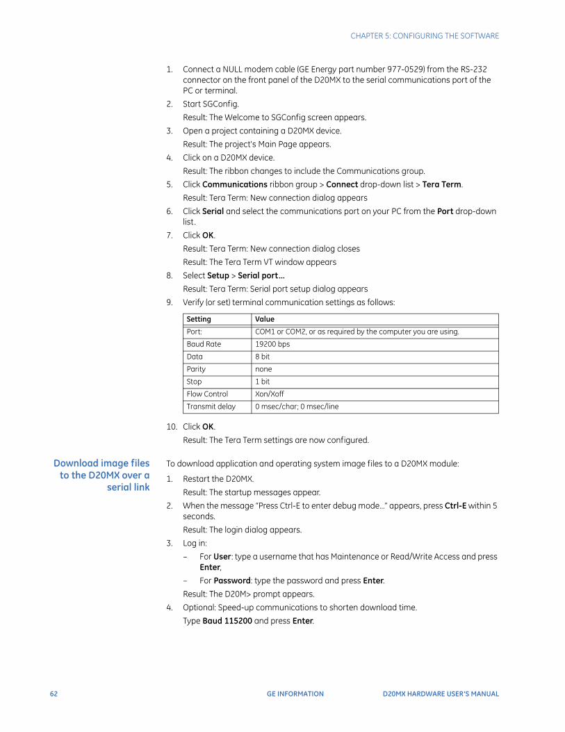
62 GE INFORMATION D20MX HARDWARE USER’S MANUAL
CHAPTER 5: CONFIGURING THE SOFTWARE
1. Connect a NULL modem cable (GE Energy part number 977-0529) from the RS-232 connector on the front panel of the D20MX to the serial communications port of the PC or terminal.
2. Start SGConfig.
Result: The Welcome to SGConfig screen appears.
3. Open a project containing a D20MX device.
Result: The project's Main Page appears.
4. Click on a D20MX device.
Result: The ribbon changes to include the Communications group.
5. Click Communications ribbon group > Connect drop-down list > Tera Term.
Result: Tera Term: New connection dialog appears
6. Click Serial and select the communications port on your PC from the Port drop-down list.
7. Click OK.
Result: Tera Term: New connection dialog closes
Result: The Tera Term VT window appears
8. Select Setup > Serial port…
Result: Tera Term: Serial port setup dialog appears
9. Verify (or set) terminal communication settings as follows:
10. Click OK.
Result: The Tera Term settings are now configured.
Download image files to the D20MX over a
serial link
To download application and operating system image files to a D20MX module:
1. Restart the D20MX.
Result: The startup messages appear.
2. When the message “Press Ctrl-E to enter debug mode…” appears, press Ctrl-E within 5 seconds.
Result: The login dialog appears.
3. Log in:
– For User: type a username that has Maintenance or Read/Write Access and press Enter,
– For Password: type the password and press Enter.
Result: The D20M> prompt appears.
4. Optional: Speed-up communications to shorten download time.
Type Baud 115200 and press Enter.
Setting Value
Port: COM1 or COM2, or as required by the computer you are using.
Baud Rate 19200 bps
Data 8 bit
Parity none
Stop 1 bit
Flow Control Xon/Xoff
Transmit delay 0 msec/char; 0 msec/line
CHAPTER 5: CONFIGURING THE SOFTWARE
D20MX HARDWARE USER’S MANUAL GE INFORMATION 63
Note: Select 57600 or 38400 if communications errors have occurred previously. Such errors can occur due to the presence of ambient EMI, a long cable length, a PC with communication limitations due to CPU speed or when using some serial to USB adapters.
Result: The D20MX is now communicating at 115,200 baud.
4.1. Select Setup > Serial port…Result: Tera Term: Serial port setup dialog appears.
4.2. Select 115,200 from the Baud Rate drop-down list.
4.3. Click OK.Result: Tera Term main window appears and is communicating at 115,200 baud.
5. Download the application image file:
5.1. Press Enter to verify that communication is active. Result: The D20M> prompt appears if the connection is active.
5.2. Type rz and press Enter to put the D20MX into the state where it is ready to receive the downloadable code file
5.3. Click File > Transfer > ZMODEM > Send from menu barResult: A dialog box opens, prompting you to locate the appl.out file that you wish to download.
5.4. Select the correct file, and click Open to start the transfer
NOTE
Do not press any keys on keyboard and do not move the Tera Term window during download.Result: The file transfer may take from less than 10 to over 30 minutes, depending on communication speed selected.When complete, the D20M> prompt appears.
6. Optional: Download the operating system image file
6.1. Press Enter to verify that communication is active. Result: The D20M> prompt will return if connection is active
6.2. Type rz and press Enter to put the D20MX into the state where it is ready to receive the downloadable code file.
6.3. Click File > Transfer > Send from menu bar.Result: A dialog box appears, prompting you to locate the vxWorks file that you wish to download.
6.4. Select the correct file, and click Open to start the transfer
NOTE
Do not press any keys on keyboard and do not move the Tera Term window during download.Result: The file transfer may take from less than 10 to over 30 minutes, depending on communication speed selected.When complete, the D20M> prompt appears.
7. Type cf to copy the image files to flash.
Result: The copy may take a few minutes to complete. When complete, the D20M> prompt appears.
8. Type el /r to ensure that log is clear.
9. Type boot to restart device.
Result: The image file load is completed.
The flash memory of the D20MX now has the new application and optional operating system image file loaded.
64 GE INFORMATION D20MX HARDWARE USER’S MANUAL
CHAPTER 5: CONFIGURING THE SOFTWARE
Configuration File Download
You can use standard SGConfig procedures to download a configuration file over the serial port.
Download software over a network connection
Procedure To download application and operating system image files to the D20MX over a network connection:
NOTE
In the event that you have selected dialog checkbox “Do not show this message again”, some of the following steps do not appear. Accordingly, ignore the affected steps.
1. Connect Ethernet port 1 of the D20MX to the Ethernet switch using the appropriate Ethernet patch cable.
Connect the PC's network adapter to the Ethernet switch using the appropriate Ethernet patch cable.
2. Start SGConfig.
Result: The Welcome to SGConfig screen appears.
3. Open a project containing the target D20MX device.
Result: The project's Main Page appears.
4. Click on the D20MX device.
Result: The Communications group appears in the ribbon.
5. Click the ribbon Communications group > Options.
Result: D2x Device Communication Options dialog appears
6. Click Interface tab > Connection Type > iSCS LAN and select the Preferred LAN you wish to use, either LAN A or LAN B. This will most likely be LAN A.
7. Click OK.
Result: D2x Device Communication Options dialog closes.
8. Click Edit ribbon group > Properties.
Result: A Dialog appears, prompting you to make a backup copy.
9. Click Yes or No depending on whether you want to make an internal backup copy.
Result: If you click Yes, a dialog appears indicating that the device is being backed up. Finally, a dialog appears indicating that the device has been backed up.
10. Click OK.
Result: The D20 Device Wizard appears
11. Click Next .
Result: The Project LAN properties appear.
12. Click Next .
Result: The hardware and other properties appear for the device.
13. Click Processor tab > Code Image sub-tab.
14. Click the button with the ellipsis (…).
Result: The Select Flash image file dialog appears.
15. Navigate to the folder containing the appl.out file and optional vxWorks file.
16. Select the appl.out file and click Open.
Result: The full pathname of the appl.out file appears in the Flash Image File box.
17. Click Next .
18. Click Finish.
Result: The project's Main Page appears with the D20MX device selected.
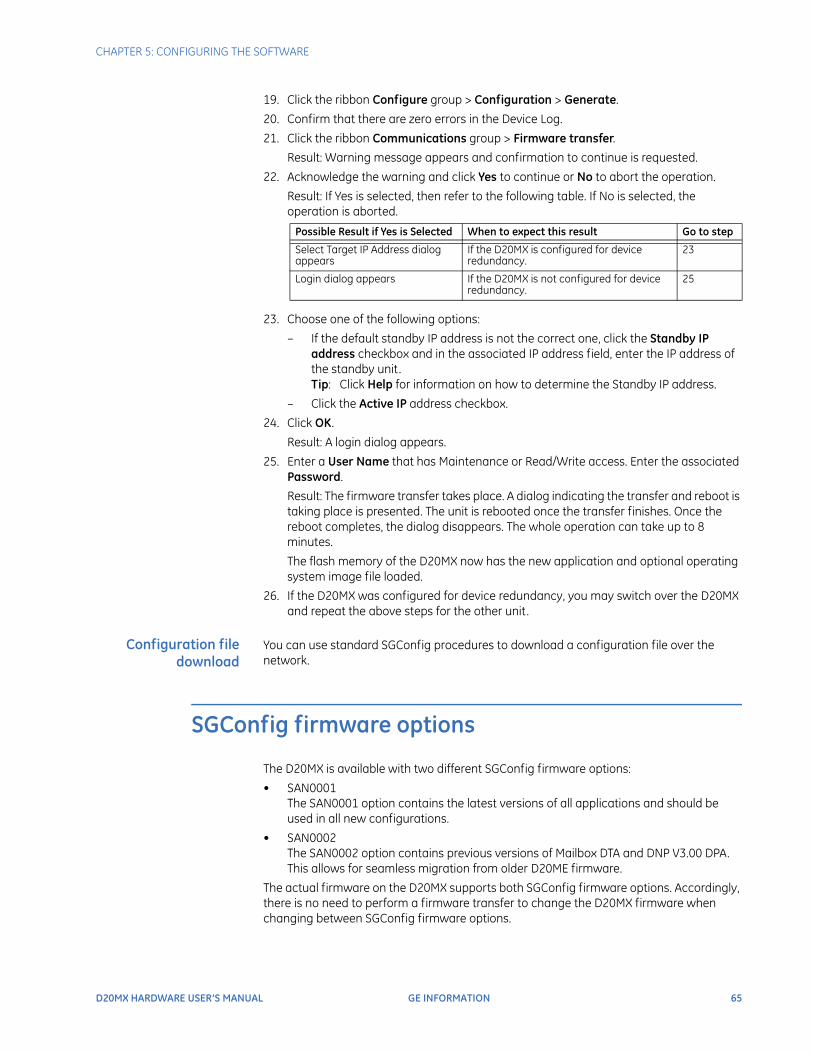
CHAPTER 5: CONFIGURING THE SOFTWARE
D20MX HARDWARE USER’S MANUAL GE INFORMATION 65
19. Click the ribbon Configure group > Configuration > Generate.
20. Confirm that there are zero errors in the Device Log.
21. Click the ribbon Communications group > Firmware transfer.
Result: Warning message appears and confirmation to continue is requested.
22. Acknowledge the warning and click Yes to continue or No to abort the operation.
Result: If Yes is selected, then refer to the following table. If No is selected, the operation is aborted.
23. Choose one of the following options:
– If the default standby IP address is not the correct one, click the Standby IP address checkbox and in the associated IP address field, enter the IP address of the standby unit. Tip: Click Help for information on how to determine the Standby IP address.
– Click the Active IP address checkbox.
24. Click OK.
Result: A login dialog appears.
25. Enter a User Name that has Maintenance or Read/Write access. Enter the associated Password.
Result: The firmware transfer takes place. A dialog indicating the transfer and reboot is taking place is presented. The unit is rebooted once the transfer finishes. Once the reboot completes, the dialog disappears. The whole operation can take up to 8 minutes.
The flash memory of the D20MX now has the new application and optional operating system image file loaded.
26. If the D20MX was configured for device redundancy, you may switch over the D20MX and repeat the above steps for the other unit.
Configuration file download
You can use standard SGConfig procedures to download a configuration file over the network.
SGConfig firmware options
The D20MX is available with two different SGConfig firmware options:
• SAN0001The SAN0001 option contains the latest versions of all applications and should be used in all new configurations.
• SAN0002The SAN0002 option contains previous versions of Mailbox DTA and DNP V3.00 DPA. This allows for seamless migration from older D20ME firmware.
The actual firmware on the D20MX supports both SGConfig firmware options. Accordingly, there is no need to perform a firmware transfer to change the D20MX firmware when changing between SGConfig firmware options.
Possible Result if Yes is Selected When to expect this result Go to step
Select Target IP Address dialog appears
If the D20MX is configured for device redundancy.
23
Login dialog appears If the D20MX is not configured for device redundancy.
25

66 GE INFORMATION D20MX HARDWARE USER’S MANUAL
CHAPTER 5: CONFIGURING THE SOFTWARE
See section: “D20MX applications” on page 16 for a list of the automation applications provided with these two firmware options.
NOTE
The D20MX firmware's ability to support multiple SGConfig firmware options is being provided in release 1.0, but is not expected to be continued in future releases.
The SANnnnn firmware options are made available within SAGnnnn files. A SAGnnnn file comprises a:
• Default Configuration, and a
• SANnnnn firmware option
Update to the SAN0001 firmware option
If the D20MX was ordered with the SAN0002 SGConfig firmware option and migration from older firmware is not required or the latest application versions are required, the following procedure can be followed to update your D20MX configuration to the SGConfig SAN0001 firmware option.
Procedure To update the D20MX configuration to the SGConfig SAN0001 firmware option:
1. Start SGConfig,
Result: The Welcome to SGConfig screen appears.
2. Open a project (e.g., TEST_PROJ).
3. Import the SAG0001 firmware option.
If the SAG0001 firmware option has already been imported, go to step 4 to open the firmware option:
3.1. Click GE > Archive > Project > Restore.Result: The Restore Project Details window appears.
3.2. Click … .Result: The Choose a File window appears.
3.3. Locate this configurations in project archives named SAG0001-01.7zip in the GE Digital Energy D20MX Documentation CD (part number 588-0075).Result: SAG0001 is displayed in the Restore Project Details window. The name can be changed if desired.
3.4. Click OK.Result: On completion a pop-up message appears: Project 'SAG0001' has been restored.
3.5. Click OK.
4. Open SAG0001: click GE > Recent Projects > select SAG0001.
5. Transfer the SAN0001 firmware option to the Project:
5.1. Click the ribbon Configure group > Miscellaneous > Firmware Library.Result: The Firmware Library window appears.
5.2. Click Copy.
5.3. Select menu item Copy To.
5.4. Select the Project you want to copy the configuration to (e.g., TEST_PROJ) from the drop-down menu.
5.5. Click OK.
5.6. Click Close.
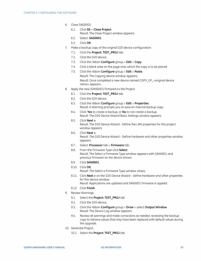
CHAPTER 5: CONFIGURING THE SOFTWARE
D20MX HARDWARE USER’S MANUAL GE INFORMATION 67
6. Close SAG0001:
6.1. Click GE > Close Project . Result: The Close Project window appears.
6.2. Select: SAG0001.
6.3. Click OK.
7. Make a backup copy of the original D20 device configuration:
7.1. Click the Project: TEST_PROJ tab.
7.2. Click the D20 device.
7.3. Click the ribbon Configure group > Edit > Copy.
7.4. Click a blank area on the page onto which the copy is to be placed.
7.5. Click the ribbon Configure group > Edit > Paste.Result: The Copying device window appears.Result: Once completed a new device named COPY_OF_<original device name> appears.
8. Apply the new (SAN0001) firmware to the Project:
8.1. Click the Project: TEST_PROJ tab.
8.2. Click the D20 device.
8.3. Click the ribbon Configure group > Edit > Properties.Result: A Warning prompts you to save an internal backup copy.
8.4. Click: Yes to create a backup, or No to not create a backup.Result: The D20 Device Wizard Basic Settings window appears.
8.5. Click Next >.Result: The D20 Device Wizard - Define the LAN properties for this project window appears.
8.6. Click Next >.Result: The D20 Device Wizard - Define hardware and other properties window appears.
8.7. Select: Processor tab > Firmware tab.
8.8. From the Firmware Type click Select .Result: The Select a Firmware Type window appears with SAN0001 and previous firmware on the device shown.
8.9. Click SAN0001.
8.10. Click OK.Result: The Select a Firmware Type window closes.
8.11. Click Next > on the D20 Device Wizard - Define hardware and other properties for this device window.Result: Applications are updated and SAN0001 firmware is applied.
8.12. Click Finish.
9. Review Warnings
9.1. Select the Project: TEST_PROJ tab
9.2. Click the D20 device.
9.3. Click the ribbon Configure group > Draw > select Output Window. Result: The Device Log window appears.
9.4. Review all warnings and make corrections as needed, reviewing the backup copy to retrieve values that may have been replaced with default values during the upgrade.
10. Generate Project,
10.1. Select the Project: TEST_PROJ tab.
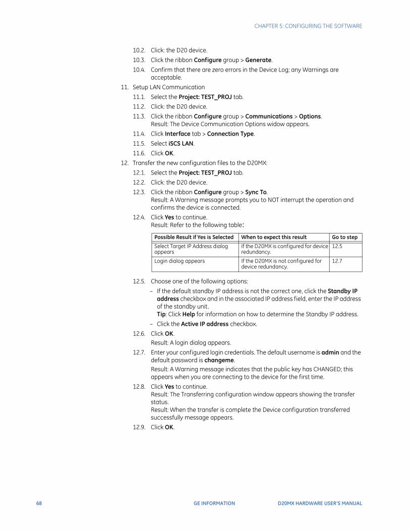
68 GE INFORMATION D20MX HARDWARE USER’S MANUAL
CHAPTER 5: CONFIGURING THE SOFTWARE
10.2. Click: the D20 device.
10.3. Click the ribbon Configure group > Generate.
10.4. Confirm that there are zero errors in the Device Log; any Warnings are acceptable.
11. Setup LAN Communication
11.1. Select the Project: TEST_PROJ tab.
11.2. Click: the D20 device.
11.3. Click the ribbon Configure group > Communications > Options.Result: The Device Communication Options widow appears.
11.4. Click Interface tab > Connection Type.
11.5. Select iSCS LAN.
11.6. Click OK.
12. Transfer the new configuration files to the D20MX:
12.1. Select the Project: TEST_PROJ tab.
12.2. Click: the D20 device.
12.3. Click the ribbon Configure group > Sync To.Result: A Warning message prompts you to NOT interrupt the operation and confirms the device is connected.
12.4. Click Yes to continue.Result: Refer to the following table:
12.5. Choose one of the following options:
– If the default standby IP address is not the correct one, click the Standby IP address checkbox and in the associated IP address field, enter the IP address of the standby unit. Tip: Click Help for information on how to determine the Standby IP address.
– Click the Active IP address checkbox.
12.6. Click OK.Result: A login dialog appears.
12.7. Enter your configured login credentials. The default username is admin and the default password is changeme.Result: A Warning message indicates that the public key has CHANGED; this appears when you are connecting to the device for the first time.
12.8. Click Yes to continue.Result: The Transferring configuration window appears showing the transfer status.Result: When the transfer is complete the Device configuration transferred successfully message appears.
12.9. Click OK.
Possible Result if Yes is Selected When to expect this result Go to step
Select Target IP Address dialog appears
If the D20MX is configured for device redundancy.
12.5
Login dialog appears If the D20MX is not configured for device redundancy.
12.7
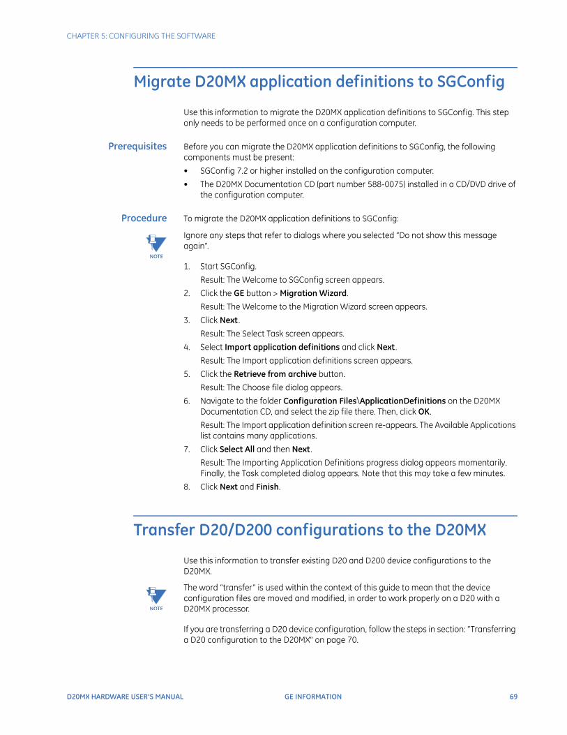
CHAPTER 5: CONFIGURING THE SOFTWARE
D20MX HARDWARE USER’S MANUAL GE INFORMATION 69
Migrate D20MX application definitions to SGConfig
Use this information to migrate the D20MX application definitions to SGConfig. This step only needs to be performed once on a configuration computer.
Prerequisites Before you can migrate the D20MX application definitions to SGConfig, the following components must be present:
• SGConfig 7.2 or higher installed on the configuration computer.
• The D20MX Documentation CD (part number 588-0075) installed in a CD/DVD drive of the configuration computer.
Procedure To migrate the D20MX application definitions to SGConfig:
NOTE
Ignore any steps that refer to dialogs where you selected “Do not show this message again”.
1. Start SGConfig.
Result: The Welcome to SGConfig screen appears.
2. Click the GE button > Migration Wizard.
Result: The Welcome to the Migration Wizard screen appears.
3. Click Next .
Result: The Select Task screen appears.
4. Select Import application definitions and click Next .
Result: The Import application definitions screen appears.
5. Click the Retrieve from archive button.
Result: The Choose file dialog appears.
6. Navigate to the folder Configuration Files\ApplicationDefinitions on the D20MX Documentation CD, and select the zip file there. Then, click OK.
Result: The Import application definition screen re-appears. The Available Applications list contains many applications.
7. Click Select All and then Next .
Result: The Importing Application Definitions progress dialog appears momentarily. Finally, the Task completed dialog appears. Note that this may take a few minutes.
8. Click Next and Finish.
Transfer D20/D200 configurations to the D20MX
Use this information to transfer existing D20 and D200 device configurations to the D20MX.
NOTE
The word “transfer” is used within the context of this guide to mean that the device configuration files are moved and modified, in order to work properly on a D20 with a D20MX processor.
If you are transferring a D20 device configuration, follow the steps in section: “Transferring a D20 configuration to the D20MX” on page 70.
70 GE INFORMATION D20MX HARDWARE USER’S MANUAL
CHAPTER 5: CONFIGURING THE SOFTWARE
If you are transferring a D200 device configuration, follow the steps in the following sections:
• Section: “Transferring a D200 configuration to the D20MX” on page 76
• Section: “Transferring a D20 configuration to the D20MX” on page 70
Transferring a D20 configuration to the D20MX
Prerequisites Before you can transfer a D20 device configuration, the following components must be present:
• SGConfig 7.2 or higher installed on the configuration computer.
• The D20MX application definitions have been migrated to the configuration computer using the instructions in Section: Migrate D20MX application definitions to SGConfig.
• The D20MX Documentation CD (part number 588-0075) installed in a CD/DVD drive of the configuration computer.
• D20 Configuration has been migrated to SGConfig with the Migration Wizard (Refer to the Migration Wizard screencast).
• To save time, you may upgrade the firmware definition of your D20 or D200 Configuration to SAN0001 or SAN0002 in ConfigProTM. If you choose to take this option, follow the instructions provided in Section: “Updating D20/D200 configurations to use the D20MX firmware definition with ConfigPro” on page 77.
Procedure To transfer a D20 or D200 device configuration to the D20MX:
NOTE
In the event that you have selected dialog checkbox “Do not show this message again”, some of the following steps do not appear. Accordingly, ignore the affected steps.
1. Start SGConfig.
Result: The Welcome to SGConfig screen appears.
2. Choose the D20MX Factory Default Configuration file, SAG0001-01.7zip or SAG0002-01.7zip. based on the following criteria:
– If transferring a configuration containing B009 versions greater than 310 and B021 versions greater than 912 use the file SAG0001-01.7zip
– If transferring a configuration containing B009 versions less than or equal to 310 and B021 versions less than or equal to 912, use the file SAG0002-01.7zip.
3. If the SAG0001 or SAG0002 firmware option has already been imported, go to step 4 to open the firmware option. Otherwise perform these steps:
3.1. Click GE button > Archive > Project > Restore.Result: The Restore Project Details window appears.
3.2. Click … .Result: The Choose a File window appears.
3.3. Navigate to the DVD/CD drive > Configuration Files > SGConfig. Result: The two files SAG0001-01.zip and SAG0002-01.zip appear in the dialog.
3.4. Select the appropriate file based on your decision in step 2.
3.5. Click OK. Result: On completion a pop-up message appears (e.g. Project 'SAG0001' has been restored).
3.6. Click OK.
4. Open the D20MX Factory Default Configuration SAG0001 or SAG0002: click GE > Recent Projects > select SAG0001-01 or SAG0002-01.
CHAPTER 5: CONFIGURING THE SOFTWARE
D20MX HARDWARE USER’S MANUAL GE INFORMATION 71
5. Copy the firmware definition from the factory default configuration to the project containing the D20 configuration (if you had opted to upgrade the firmware in ConfigPro, then this step is not necessary):
5.1. Click the ribbon Configure group > Miscellaneous > Firmware Library.Result: The Firmware Library window appears with the firmware definition selected.
5.2. Click Copy.Result: The Firmware Information window appears.
5.3. Set the Project Name in the Copy To region to the project containing the D20 configuration.
5.4. Click OK.Result: The Firmware Information window closes.
5.5. Click Close.Result: The Firmware Library window closes.
6. Export the RADIUS roles from the default configuration:
6.1. Double-click the D20 device named FAC_DEF.Result: The Application List popup appears.
6.2. Double-click the WESMAINT II+ application.Result: The WESMAINT II+ table icon set appears.
6.3. Right-click the RADIUS Role Table icon and select ExportResult: The Export Options dialog appears.
6.4. Click on the button containing an ellipsis (...) under the Place export files in area.Result: The Choose a folder dialog appears.
6.5. Browse to a folder (e.g. your Desktop) and click OK, OK, and Cancel.Result: The main page of the project appears.
7. Export the IP Redundancy Monitor point descriptors from the default configuration:
7.1. Double-click the D20 device named FAC_DEFResult: The Application List popup appears.
7.2. Double-click the System Point Database application.Result: The System Point Database Properties dialog appears.
7.3. Select IP Redundancy Monitor and click Descriptors.Result: The Point Descriptors dialog appears.
7.4. Click on the Export button.Result: The Export Point Descriptors dialog appears.
7.5. Click OK.Result: The Browse For Folder dialog appears.
7.6. Browse to a folder and click OK, OK and OK.Result: The main page of the project appears.
8. Close the D20MX Factory Default Configuration (i.e. SAG0001 or SAG0002):
8.1. Click GE > Close Project . Result: The Close Project window appears.
8.2. Select: SAG0001-01 or SAG0002-01.
8.3. Click OK.
9. Open the SGConfig project containing the D20 device.:
9.1. Click the GE button.
9.2. Click the required SGConfig project in the Recent Projects list or select the Open Project menu item.
72 GE INFORMATION D20MX HARDWARE USER’S MANUAL
CHAPTER 5: CONFIGURING THE SOFTWARE
10. Make a backup copy of the original D20 device configuration:
10.1. Click the Project tab of the original D20 device configuration.
10.2. Click the D20 device.
10.3. Click the ribbon Configure group > Edit > Copy.
10.4. Click a blank area on the page onto which the copy is to be placed.
10.5. Click the ribbon Configure group > Edit > Paste.Result: The Copying device window appears. Result: Once completed a new device named COPY_OF_<original device name> appears.
11. Select a D20MX processor from the D20 Device Wizard:
11.1. Click the Project tab of the original D20 device configuration.
11.2. Click the D20 device.
11.3. Click the ribbon Configure group > Edit > Properties.Result: A Warning prompts you to save an internal backup copy.
11.4. Click Yes to create a backup, or No to not create a backup.Result: The D20 Device Wizard Basic Settings window appears.
11.5. Click Next until the Processor tab appears.
11.6. Click the Processor tab > General sub-tab.
11.7. From the Part Number field, click Select .Result: The Select a Processor Card window appears.
11.8. Select one of the three D20MX processor type part numbers (526-3001, 526-3003 or 526-3005).
11.9. Click Next , Next , Firmware tab, Select .
11.10. Select either SAN0001 / 001 or SAN0002 / 001. If you had opted to upgrade the firmware in ConfigPro, then this step is not necessary.
11.11. Click OK.
11.12. Click Next , Finish.Result: The D20 Device Wizard closes.
12. Review warnings:
12.1. Click the Project tab of the original D20 device configuration.
12.2. Click the D20 device.
12.3. Click the ribbon Configure group > Draw > select Output Window.Result: The Device Log window appears.
12.4. Review all warnings and make corrections as needed, reviewing the backup copy to retrieve values that may have been replaced with default values during the upgrade.
13. Ensure the BOOTP client is disabled:
13.1. Click the Project tab of the original D20 device configuration.
13.2. Click the D20 device.
13.3. Click the ribbon Edit group > Properties.Result: A Warning prompts you to save an internal backup copy.
13.4. Click Yes to create a backup, or No to not create a backup.Result: The D20 Device Wizard appears.
13.5. Click Next until the Processor tab appears.
13.6. Click the LAN Settings tab > General sub-tab.
13.7. From the BOOTP Settings frame, ensure Not Used is checked.
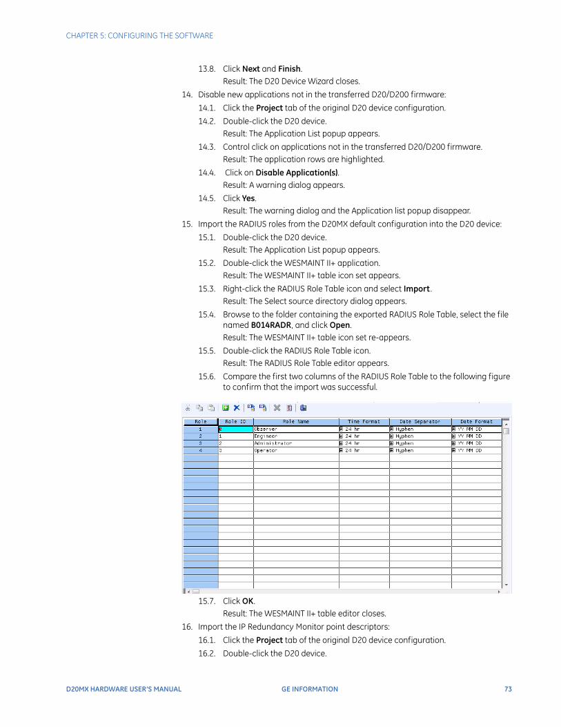
CHAPTER 5: CONFIGURING THE SOFTWARE
D20MX HARDWARE USER’S MANUAL GE INFORMATION 73
13.8. Click Next and Finish.Result: The D20 Device Wizard closes.
14. Disable new applications not in the transferred D20/D200 firmware:
14.1. Click the Project tab of the original D20 device configuration.
14.2. Double-click the D20 device.Result: The Application List popup appears.
14.3. Control click on applications not in the transferred D20/D200 firmware. Result: The application rows are highlighted.
14.4. Click on Disable Application(s).Result: A warning dialog appears.
14.5. Click Yes.Result: The warning dialog and the Application list popup disappear.
15. Import the RADIUS roles from the D20MX default configuration into the D20 device:
15.1. Double-click the D20 device.Result: The Application List popup appears.
15.2. Double-click the WESMAINT II+ application.Result: The WESMAINT II+ table icon set appears.
15.3. Right-click the RADIUS Role Table icon and select Import .Result: The Select source directory dialog appears.
15.4. Browse to the folder containing the exported RADIUS Role Table, select the file named B014RADR, and click Open.Result: The WESMAINT II+ table icon set re-appears.
15.5. Double-click the RADIUS Role Table icon.Result: The RADIUS Role Table editor appears.
15.6. Compare the first two columns of the RADIUS Role Table to the following figure to confirm that the import was successful.
15.7. Click OK.Result: The WESMAINT II+ table editor closes.
16. Import the IP Redundancy Monitor point descriptors:
16.1. Click the Project tab of the original D20 device configuration.
16.2. Double-click the D20 device.
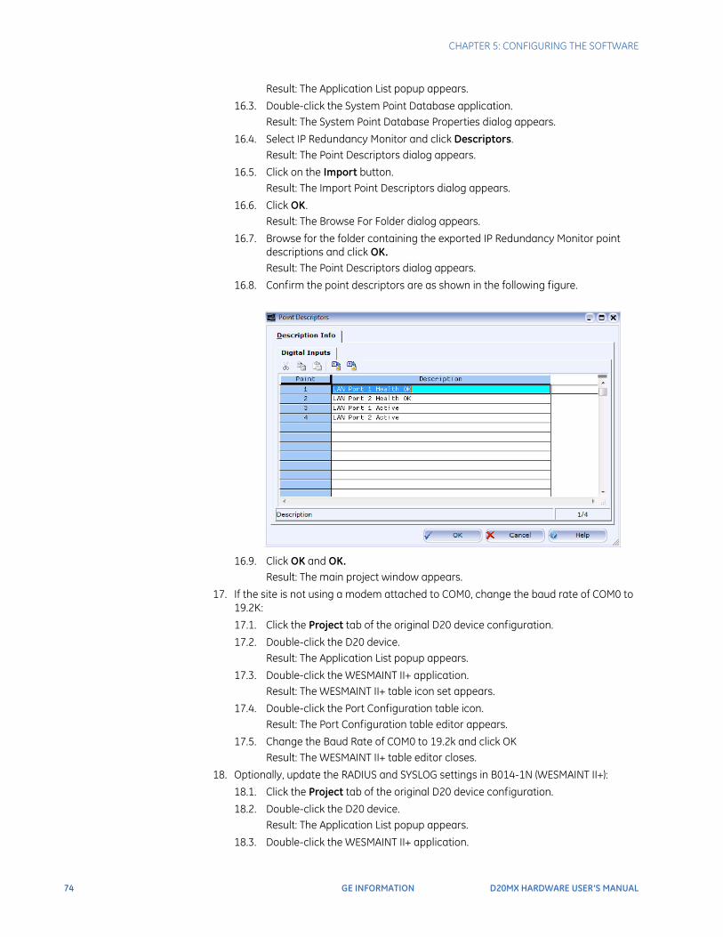
74 GE INFORMATION D20MX HARDWARE USER’S MANUAL
CHAPTER 5: CONFIGURING THE SOFTWARE
Result: The Application List popup appears.
16.3. Double-click the System Point Database application.Result: The System Point Database Properties dialog appears.
16.4. Select IP Redundancy Monitor and click Descriptors.Result: The Point Descriptors dialog appears.
16.5. Click on the Import button.Result: The Import Point Descriptors dialog appears.
16.6. Click OK.Result: The Browse For Folder dialog appears.
16.7. Browse for the folder containing the exported IP Redundancy Monitor point descriptions and click OK.Result: The Point Descriptors dialog appears.
16.8. Confirm the point descriptors are as shown in the following figure.
16.9. Click OK and OK.Result: The main project window appears.
17. If the site is not using a modem attached to COM0, change the baud rate of COM0 to 19.2K:
17.1. Click the Project tab of the original D20 device configuration.
17.2. Double-click the D20 device.Result: The Application List popup appears.
17.3. Double-click the WESMAINT II+ application.Result: The WESMAINT II+ table icon set appears.
17.4. Double-click the Port Configuration table icon.Result: The Port Configuration table editor appears.
17.5. Change the Baud Rate of COM0 to 19.2k and click OKResult: The WESMAINT II+ table editor closes.
18. Optionally, update the RADIUS and SYSLOG settings in B014-1N (WESMAINT II+):
18.1. Click the Project tab of the original D20 device configuration.
18.2. Double-click the D20 device.Result: The Application List popup appears.
18.3. Double-click the WESMAINT II+ application.
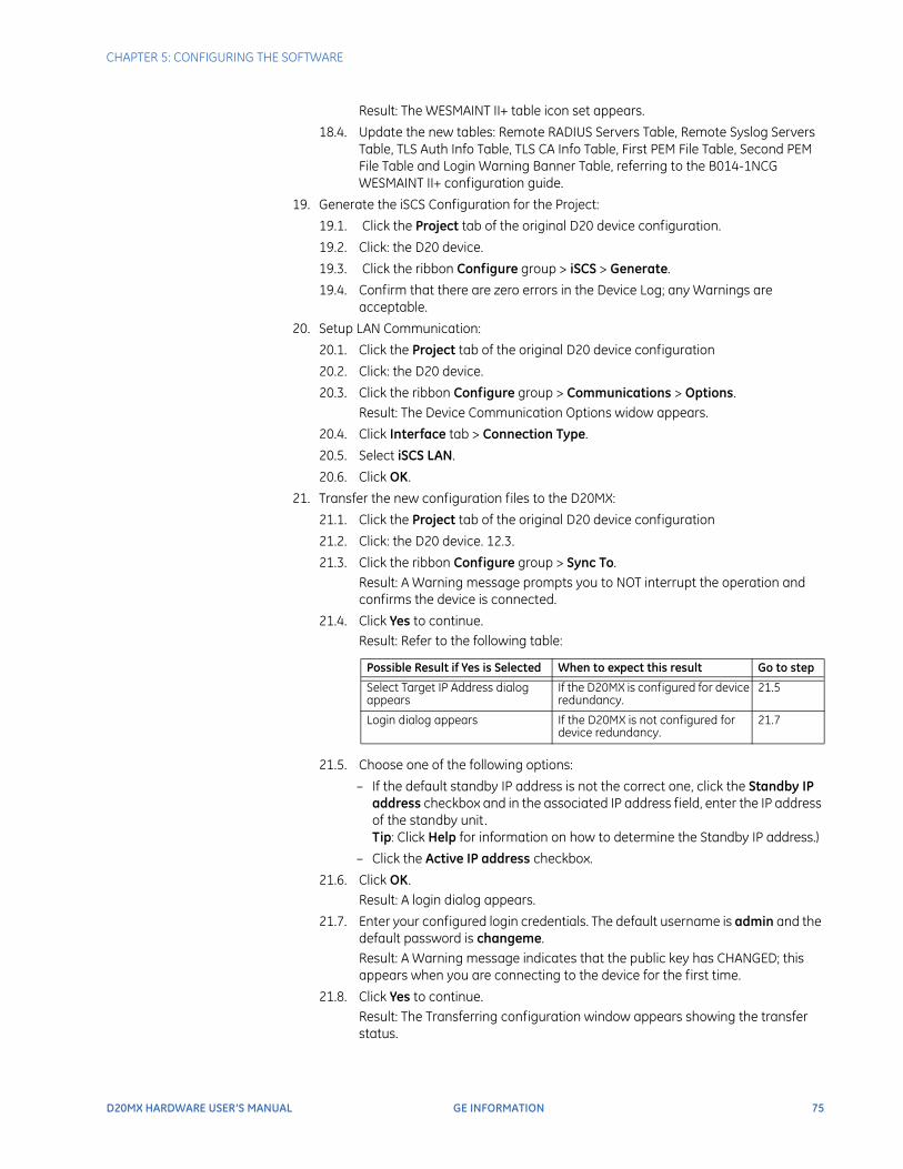
CHAPTER 5: CONFIGURING THE SOFTWARE
D20MX HARDWARE USER’S MANUAL GE INFORMATION 75
Result: The WESMAINT II+ table icon set appears.
18.4. Update the new tables: Remote RADIUS Servers Table, Remote Syslog Servers Table, TLS Auth Info Table, TLS CA Info Table, First PEM File Table, Second PEM File Table and Login Warning Banner Table, referring to the B014-1NCG WESMAINT II+ configuration guide.
19. Generate the iSCS Configuration for the Project:
19.1. Click the Project tab of the original D20 device configuration.
19.2. Click: the D20 device.
19.3. Click the ribbon Configure group > iSCS > Generate.
19.4. Confirm that there are zero errors in the Device Log; any Warnings are acceptable.
20. Setup LAN Communication:
20.1. Click the Project tab of the original D20 device configuration
20.2. Click: the D20 device.
20.3. Click the ribbon Configure group > Communications > Options.Result: The Device Communication Options widow appears.
20.4. Click Interface tab > Connection Type.
20.5. Select iSCS LAN.
20.6. Click OK.
21. Transfer the new configuration files to the D20MX:
21.1. Click the Project tab of the original D20 device configuration
21.2. Click: the D20 device. 12.3.
21.3. Click the ribbon Configure group > Sync To.Result: A Warning message prompts you to NOT interrupt the operation and confirms the device is connected.
21.4. Click Yes to continue.Result: Refer to the following table:
21.5. Choose one of the following options:
– If the default standby IP address is not the correct one, click the Standby IP address checkbox and in the associated IP address field, enter the IP address of the standby unit.Tip: Click Help for information on how to determine the Standby IP address.)
– Click the Active IP address checkbox.
21.6. Click OK.Result: A login dialog appears.
21.7. Enter your configured login credentials. The default username is admin and the default password is changeme.Result: A Warning message indicates that the public key has CHANGED; this appears when you are connecting to the device for the first time.
21.8. Click Yes to continue.Result: The Transferring configuration window appears showing the transfer status.
Possible Result if Yes is Selected When to expect this result Go to step
Select Target IP Address dialog appears
If the D20MX is configured for device redundancy.
21.5
Login dialog appears If the D20MX is not configured for device redundancy.
21.7
76 GE INFORMATION D20MX HARDWARE USER’S MANUAL
CHAPTER 5: CONFIGURING THE SOFTWARE
Result: When the transfer is complete the Device configuration transferred successfully message appears.
21.9. Click OK.
NOTE
All users that existed in the transferred D20/D200 configuration now have the default password: changeme. Change these passwords using the passwd command in the D20MX Shell. Refer to the WESMAINT II+ for D20MX Configuration Guide B014- 0NCG for details of this command.
NOTE
If the D20MX was configured for device redundancy, once the sync to operation is complete, the standby unit reboots and comes up again as standby with the new configuration. If desired, switch over and synchronize the new configuration to the other unit through the “Switch Over” and “Database Sync” functions available in the WESMAINT System Functions menu. Refer to the WESMAINT II+ for D20MX User's Guide B014-0NUG for details on these functions.
Transferring a D200 configuration to the D20MX
Prerequisites Before you can transfer a D200 device configuration, the following components must be present:
• SGConfig 7.2 or higher installed on the configuration computer
• D200 Configuration has been migrated to SGConfig with the Migration Wizard (Refer to the Migration Wizard screencast).
Procedure
Migrating a multi-processor D200 will only transfer the application configurations on the first processor.This is manually resolved by moving applications from other processors to the first processor using the SGConfig device editing functions BEFORE converting the device to a D20 in the instructions below.
Single and multi-processor D200 devices must first be changed into D20 devices before the D20MX processor card option can be selected. To change a D200 device into a D20 device perform the following steps:
1. Start SGConfig.
Result: The Welcome to SGConfig screen appears.
2. Open a project containing the D200 device you want to transfer to a D20MX:
2.1. Click the GE button.
2.2. Click the required SGConfig project in the Recent Projects list or select the Open Project menu item.
3. Make a backup copy of the original D200 device configuration:
3.1. Click the Project tab of the original D200 device configuration.
3.2. Click the D200 device.
3.3. Click the ribbon Configure group > Edit > Copy.
3.4. Click a blank area on the page onto which the copy is to be placed.
3.5. Click the ribbon Configure group > Edit > Paste.Result: The Copying device window appears Result: Once completed a new device named COPY_OF_<original device name> appears.
CHAPTER 5: CONFIGURING THE SOFTWARE
D20MX HARDWARE USER’S MANUAL GE INFORMATION 77
4. Click the ribbon Configuration group > Change Type.
Result: The Change Device window appears.
5. Select type D20 and click OK.
6. Follow the steps in section: Transferring a D20 configuration to the D20MX.
Updating D20/D200 configurations to use the D20MX firmware definition with ConfigPro
Use this information to update the firmware definition of an existing D20 and D200 device configuration to the D20MX firmware definition. The result is a device archive that you can migrate into SGConfig for the purpose of transferring the D20/D200 configuration to the D20MX. The remaining steps of the transfer are described in “Transfer D20/D200 configurations to the D20MX” on page 69.If you are updating a D20 device configuration, follow the steps in section: Updating a D20 configuration to use the D20MX.If you are transferring a D200 device configuration, follow the steps in the following sections:
• “Updating a D200 configuration to use the D20MX firmware definition with ConfigPro” on page 79
• “Updating a D20 configuration to use the D20MX firmware definition with ConfigPro” on page 77
Updating a D20 configuration to use the D20MX firmware definition with ConfigPro
Prerequisites Before you can update the firmware definition of a D20 device configuration, the following components must be present:
• ConfigPro 5.03 or higher installed on the configuration computer.
• The D20MX Documentation CD (part number 588-0075) installed in a CD/DVD drive of the configuration computer.
Procedure To update a D20 or D200 device configuration to the D20MX:
1. Start Config Pro 5.03 or higher.
Result: The main window of ConfigPro appears with the tree view of the project directory on the left .
2. Choose the D20MX Factory Default Configuration file, 10730-01.zip or 10731-01.zip. based on the following criteria:
– If transferring a configuration containing B009 versions greater than 310 and B021 versions greater than 912 use the file 10730-01.zip
– If transferring a configuration containing B009 versions less than or equal to 310 and B021 versions less than or equal to 912, use the file 10731-01.zip.
3. Select from the menu bar Project > Archive Project > Restore.
Result: The Restore Project from ZIP File dialog appears
4. Under the Select Source Project ZIP File area, click the document icon.
Result: The Select a Project ZIP file to Restore dialog appears.
5. Navigate to the DVD/CD drive > Configuration Files > ConfigPro.
78 GE INFORMATION D20MX HARDWARE USER’S MANUAL
CHAPTER 5: CONFIGURING THE SOFTWARE
Result: The two files 10730-01.zip and 10731-01.zip appear in the dialog.
6. Select the appropriate file based on your decision made in the second step and click the Select button.
Result: The Restore Project from ZIP File dialog appears with the selected file showing under the Select Source Project ZIP File area.
7. Under the “Restore To” area, click the folder icon.
Result: The Select the Destination Project Directory dialog appears.
8. Navigate to your ConfigPro project folder on a hard drive of the configuration computer. The project folder is typically named C:\WESDATA.
Result: The contents of the project folder are displayed, and the file named WPL400.DB is selected.
9. Click the Select button.
Result: The Restore Project from ZIP File dialog reappears with the Project Directory set to the folder you selected in the previous step.
10. Change the Project Name if desired and click OK.
Result: The main window of ConfigPro appears with the tree view of the project directory on the left. The new D20MX factory default project appears in the tree view.
11. Double-click on the D20MX factory default project.
Result: The Main Page of the D20MX factory default project appears with the FAC_DEF device placed on the page.
12. Double-click the FAC_DEF device.
Result: The Missing Applications! dialog appears.
13. Click the Install button.
Result: The Select the Source Application Definition Directory dialog appears.
14. Navigate to the DVD/CD drive > DEFNS > APPLDEF.
Result: The contents of the APPLDEF folder is displayed with the file DAL100.DB selected.
15. Click Select .
Result: Messages are displayed about the application definitions being extracted to the configuration computer, and finally the Data Collection Applications of the FAC_DEF device appear.
16. Close the device configuration by clicking on the door icon.
Result: The Main Page of the D20MX factory default project appears with the FAC_DEF device appearing on the page.
17. Click from the menu bar, Device > Firmware.
Result: The Firmware Library dialog appears. Depending on which factory default project you chose in the second step, either SAN0001 or SAN0002 will appear.
18. Click Copy.
Result: The Firmware Information dialog appears.
19. In the “Copy To” area select the Project Directory and Project Name of the project you want to transfer to the D20MX.
Result: The “Copy To” area contains the Project Directory and Project Name of the project you want to transfer to the D20MX.
20. Click OK, Close and the door icon
Result: The main window of ConfigPro appears with the tree view of the project directory on the left.
21. Make a backup copy of your project.
21.1. Select from the menu bar, Project > Copy Project .
CHAPTER 5: CONFIGURING THE SOFTWARE
D20MX HARDWARE USER’S MANUAL GE INFORMATION 79
Result: The Copy Project dialog appears.
21.2. In the “From” area, navigate to the folder and select the project you want to transfer to the D20MX.
21.3. In the “To” area, enter a new unique name for the project.
21.4. Click OK.Result: The main window of ConfigPro appears with the tree view of the project directory on the left.
22. On the tree view displayed to the left, navigate to the copied project and double-click on the project name.
Result: The main window of the copied project appears.
23. Right-click on the D20 device you want to transfer and select Properties.
Result: The D20 Device Properties window appears.
24. Click the Processor tab and the Firmware tab. Then click Select .
Result: The Select a Firmware Type dialog appears. Depending on which factory default project you chose in the second step, either SAN0001 or SAN0002 will appear.
25. Select whichever of SAN0001 or SAN0002 appears and click OK and OK.
Result: A confirmation dialog appears asking if you want to make a backup copy now.
26. Click No because you have already made a backup.
Result: Messages will appear indicating the upgrade is in progress. Messages appear in the Device Log indicating the results of the upgrade. The D20 device appears with a red dot.
27. Review all warnings and make corrections as needed, reviewing the original copy to retrieve values that may have been replaced with default values during the upgrade
28. Right-click on the device and click Generate.
Result: The device is displayed without a red dot.
29. Right-click on the device and click Archive > Save.
Result: The Save Device to ZIP File dialog appears.
30. In the “Save To” area, click the folder icon.
Result: A dialog appears with the title “Select a directory in which to save the project”.
31. Navigate to a folder on your PC where you would like to save the device archive and click Select and OK.
32. Close ConfigPro.
33. Migrate the D20 Device Archive into SGConfig using the Migration Wizard (Refer to the Migration Wizard screencast).
Updating a D200 configuration to use the D20MX firmware definition with ConfigPro
Prerequisites Before you can update the firmware definition of a D200 device configuration, the following components must be present
• ConfigPro 5.03 or higher installed on the configuration computer.
• The D20MX Documentation CD (part number 588-0075) installed in a CD/DVD drive of the configuration computer.
Procedure
Migrating a multi-processor D200 will only transfer the application configurations on the first processor.
80 GE INFORMATION D20MX HARDWARE USER’S MANUAL
CHAPTER 5: CONFIGURING THE SOFTWARE
This is manually resolved by moving applications from other processors to the first processor using the ConfigPro device editing functions BEFORE converting the device to a D20 in the instructions below.Single and multi-processor D200 devices must first be changed into D20 devices before the D20MX firmware definition can be selected. To change a D200 device into a D20 device perform the following steps:
1. Start ConfigPro 5.03 or higher.
Result: The main window of ConfigPro appears with the tree view of the project directory on the left.
2. Make a backup copy of the project you want to transfer to the D20MX.
2.1. Select from the menu, Project > Copy Project .Result: The Copy Project dialog appears.
2.2. In the “From” area, navigate to the folder and select the project you want to transfer to the D20MX.
2.3. In the “To” area, enter a new unique name for the project.
2.4. Click OK.Result: The main window of ConfigPro appears with the tree view of the project directory on the left.
3. On the tree view displayed to the left, navigate to the project and double-click on the project name.
Result: The main window of the copied project appears
4. Right-click on the D20 device you want to transfer and select Tools > Change.
Result: The Change Device window appears.
5. Select type D20 and click OK.
6. Follow the steps in section: “Updating a D20 configuration to use the D20MX firmware definition with ConfigPro” on page 77.
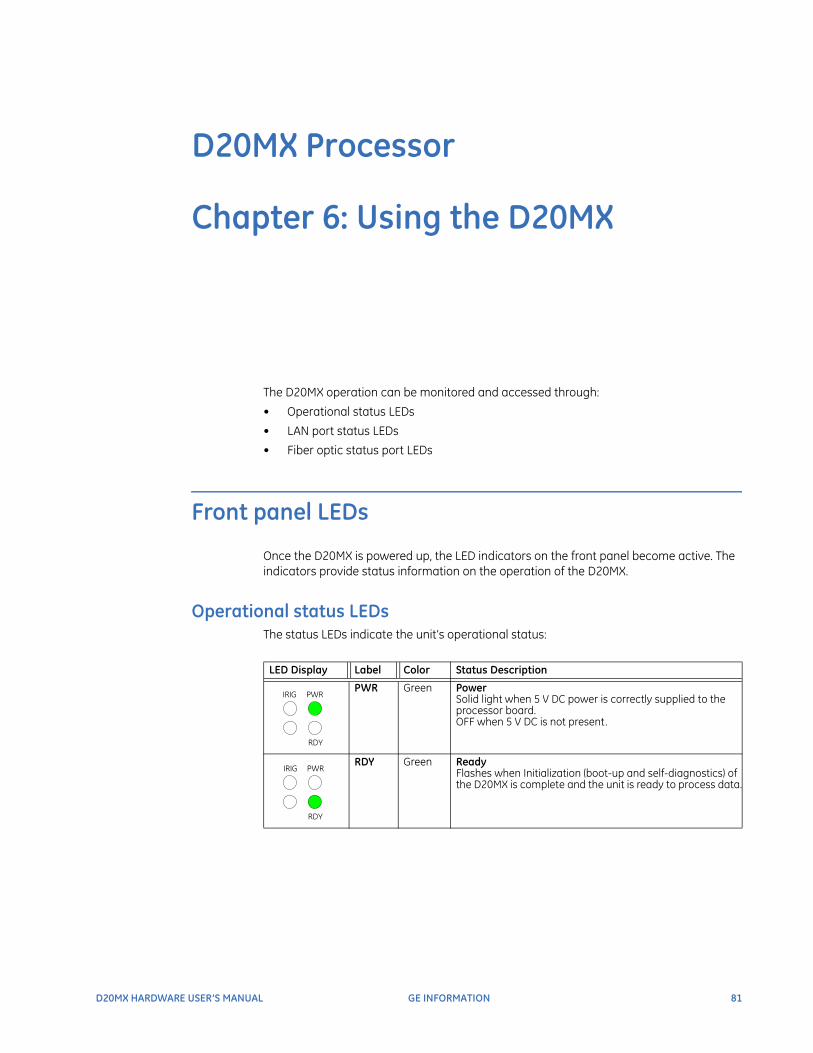
D20MX HARDWARE USER’S MANUAL GE INFORMATION 81
D20MX Processor
Chapter 6: Using the D20MX
Using the D20MX
The D20MX operation can be monitored and accessed through:
• Operational status LEDs
• LAN port status LEDs
• Fiber optic status port LEDs
Front panel LEDs
Once the D20MX is powered up, the LED indicators on the front panel become active. The indicators provide status information on the operation of the D20MX.
Operational status LEDsThe status LEDs indicate the unit’s operational status:
LED Display Label Color Status Description
PWR Green PowerSolid light when 5 V DC power is correctly supplied to the processor board.OFF when 5 V DC is not present.
RDY Green ReadyFlashes when Initialization (boot-up and self-diagnostics) of the D20MX is complete and the unit is ready to process data.
IRIG PWR
RDY
IRIG PWR
RDY
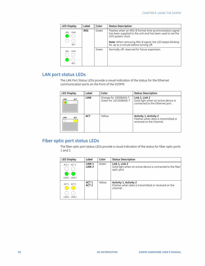
82 GE INFORMATION D20MX HARDWARE USER’S MANUAL
CHAPTER 6: USING THE D20MX
LAN port status LEDsThe LAN Port Status LEDs provide a visual indication of the status for the Ethernet communication ports on the front of the D20MX.
Fiber optic port status LEDsThe fiber optic port status LEDs provide a visual indication of the status for fiber optic ports 1 and 2.
IRIG Green Flashes when an IRIG-B format time synchronization signal has been supplied to the unit and has been used to set the D20 system clock.Note: When removing IRIG-B signal, the LED keeps blinking for up to a minute before turning off.
Green Normally off; reserved for future expansion.
LED Display Label Color Status Description
IRIG PWR
RDY
IRIG PWR
RDY
IRIG PWR
RDY
LED Display Label Color Status Description
LINK Orange for 1000BASE-T.Green for 10/100BASE-T
Link 1, Link 2Solid light when an active device is connected to the Ethernet port.
ACT Yellow Activity 1, Activity 2Flashes when data is transmitted or received on the channel.
LINK ACT
LINK ACT
LED Display Label Color Status Description
LINK 1LINK 2
Green Link 1, Link 2Solid light when an active device is connected to the fiber optic port.
ACT 1ACT 2
Yellow Activity 1, Activity 2Flashes when data is transmitted or received on the channel.
ACT 1 ACT 2
LINK 2LINK 1
ACT 1 ACT 2
LINK 2LINK 1
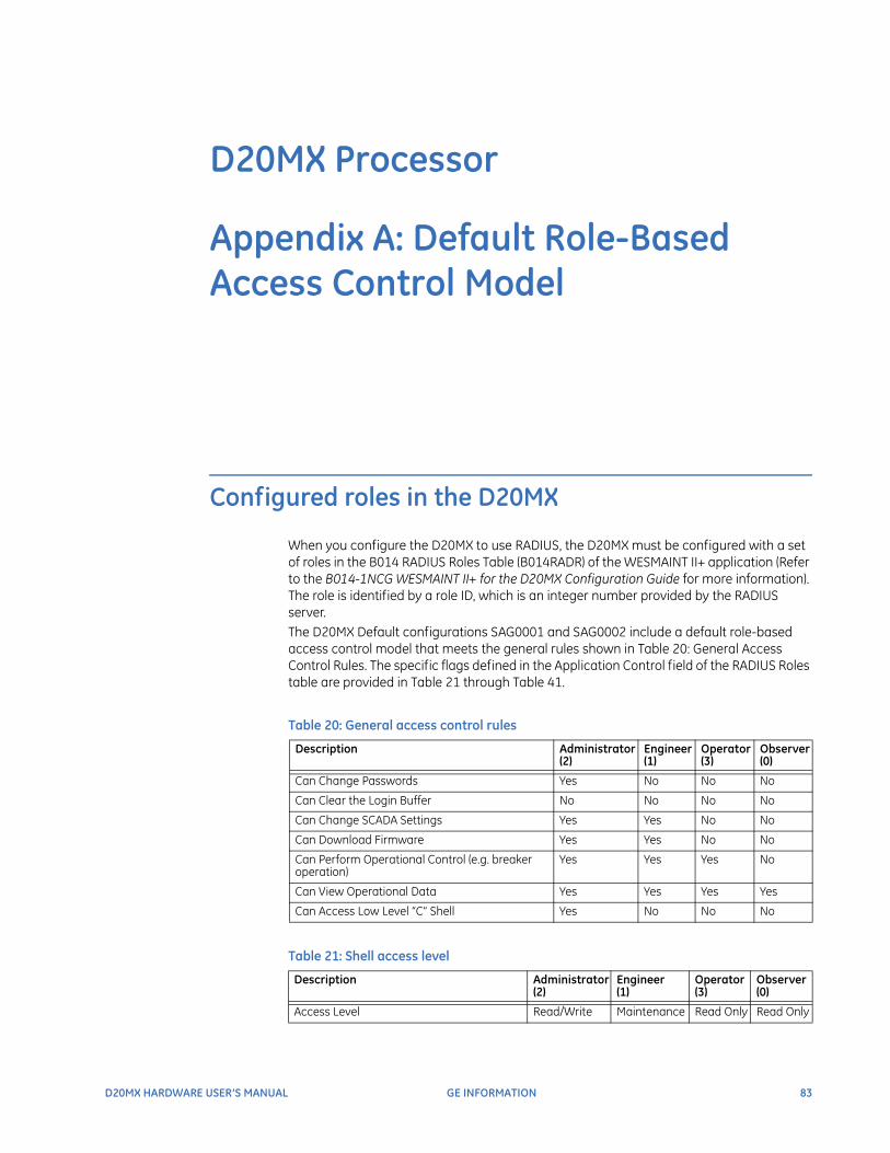
D20MX HARDWARE USER’S MANUAL GE INFORMATION 83
D20MX Processor
Appendix A: Default Role-Based Access Control Model
Default Role-Based Access Control Model
Configured roles in the D20MX
When you configure the D20MX to use RADIUS, the D20MX must be configured with a set of roles in the B014 RADIUS Roles Table (B014RADR) of the WESMAINT II+ application (Refer to the B014-1NCG WESMAINT II+ for the D20MX Configuration Guide for more information). The role is identified by a role ID, which is an integer number provided by the RADIUS server. The D20MX Default configurations SAG0001 and SAG0002 include a default role-based access control model that meets the general rules shown in Table 20: General Access Control Rules. The specific flags defined in the Application Control field of the RADIUS Roles table are provided in Table 21 through Table 41.
Table 20: General access control rules
Table 21: Shell access level
Description Administrator (2)
Engineer (1)
Operator (3)
Observer (0)
Can Change Passwords Yes No No No
Can Clear the Login Buffer No No No No
Can Change SCADA Settings Yes Yes No No
Can Download Firmware Yes Yes No No
Can Perform Operational Control (e.g. breaker operation)
Yes Yes Yes No
Can View Operational Data Yes Yes Yes Yes
Can Access Low Level “C” Shell Yes No No No
Description Administrator (2)
Engineer (1)
Operator (3)
Observer (0)
Access Level Read/Write Maintenance Read Only Read Only
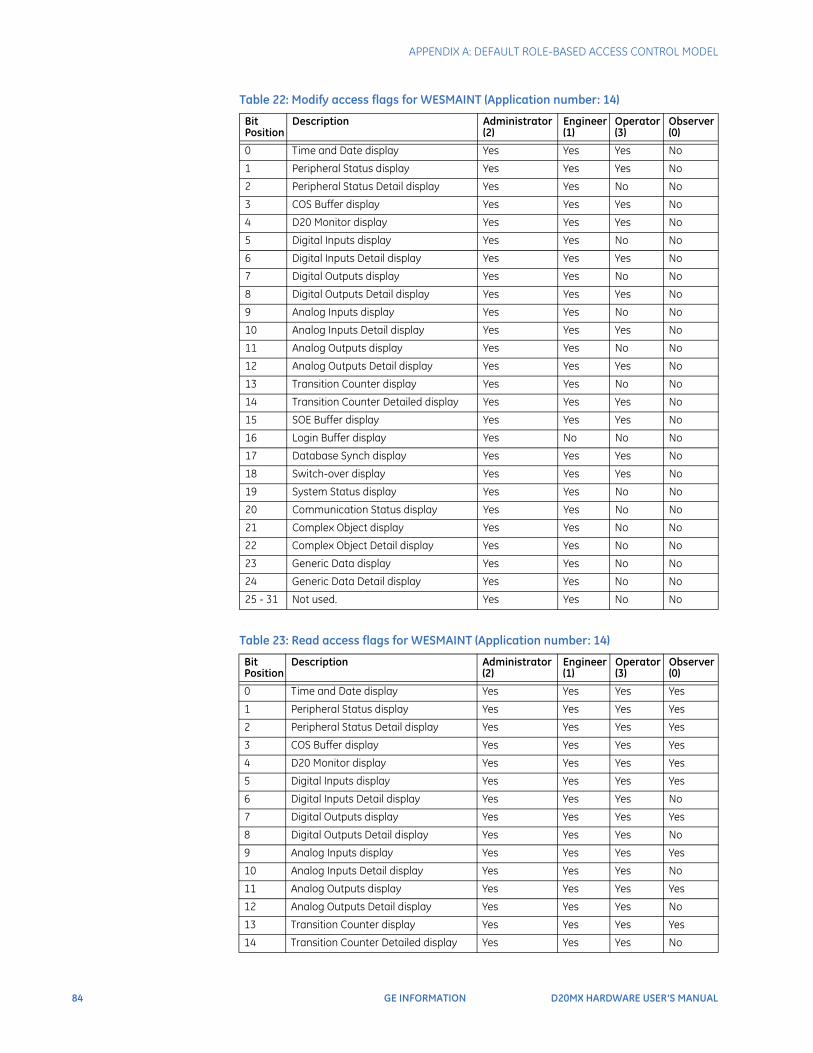
84 GE INFORMATION D20MX HARDWARE USER’S MANUAL
APPENDIX A: DEFAULT ROLE-BASED ACCESS CONTROL MODEL
Table 22: Modify access flags for WESMAINT (Application number: 14)
Table 23: Read access flags for WESMAINT (Application number: 14)
Bit Position
Description Administrator (2)
Engineer (1)
Operator (3)
Observer (0)
0 Time and Date display Yes Yes Yes No
1 Peripheral Status display Yes Yes Yes No
2 Peripheral Status Detail display Yes Yes No No
3 COS Buffer display Yes Yes Yes No
4 D20 Monitor display Yes Yes Yes No
5 Digital Inputs display Yes Yes No No
6 Digital Inputs Detail display Yes Yes Yes No
7 Digital Outputs display Yes Yes No No
8 Digital Outputs Detail display Yes Yes Yes No
9 Analog Inputs display Yes Yes No No
10 Analog Inputs Detail display Yes Yes Yes No
11 Analog Outputs display Yes Yes No No
12 Analog Outputs Detail display Yes Yes Yes No
13 Transition Counter display Yes Yes No No
14 Transition Counter Detailed display Yes Yes Yes No
15 SOE Buffer display Yes Yes Yes No
16 Login Buffer display Yes No No No
17 Database Synch display Yes Yes Yes No
18 Switch-over display Yes Yes Yes No
19 System Status display Yes Yes No No
20 Communication Status display Yes Yes No No
21 Complex Object display Yes Yes No No
22 Complex Object Detail display Yes Yes No No
23 Generic Data display Yes Yes No No
24 Generic Data Detail display Yes Yes No No
25 - 31 Not used. Yes Yes No No
Bit Position
Description Administrator (2)
Engineer (1)
Operator (3)
Observer (0)
0 Time and Date display Yes Yes Yes Yes
1 Peripheral Status display Yes Yes Yes Yes
2 Peripheral Status Detail display Yes Yes Yes Yes
3 COS Buffer display Yes Yes Yes Yes
4 D20 Monitor display Yes Yes Yes Yes
5 Digital Inputs display Yes Yes Yes Yes
6 Digital Inputs Detail display Yes Yes Yes No
7 Digital Outputs display Yes Yes Yes Yes
8 Digital Outputs Detail display Yes Yes Yes No
9 Analog Inputs display Yes Yes Yes Yes
10 Analog Inputs Detail display Yes Yes Yes No
11 Analog Outputs display Yes Yes Yes Yes
12 Analog Outputs Detail display Yes Yes Yes No
13 Transition Counter display Yes Yes Yes Yes
14 Transition Counter Detailed display Yes Yes Yes No
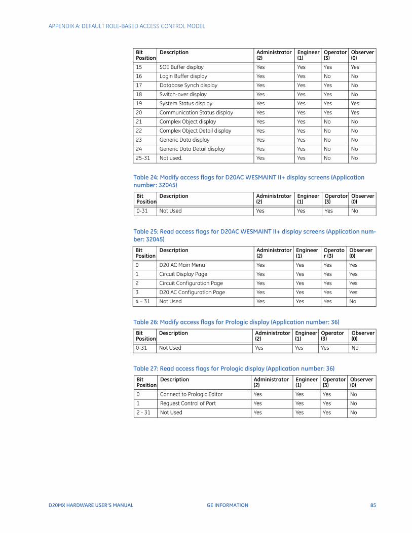
APPENDIX A: DEFAULT ROLE-BASED ACCESS CONTROL MODEL
D20MX HARDWARE USER’S MANUAL GE INFORMATION 85
Table 24: Modify access flags for D20AC WESMAINT II+ display screens (Application number: 32045)
Table 25: Read access flags for D20AC WESMAINT II+ display screens (Application num-ber: 32045)
Table 26: Modify access flags for Prologic display (Application number: 36)
Table 27: Read access flags for Prologic display (Application number: 36)
15 SOE Buffer display Yes Yes Yes Yes
16 Login Buffer display Yes Yes No No
17 Database Synch display Yes Yes Yes No
18 Switch-over display Yes Yes Yes No
19 System Status display Yes Yes Yes Yes
20 Communication Status display Yes Yes Yes Yes
21 Complex Object display Yes Yes No No
22 Complex Object Detail display Yes Yes No No
23 Generic Data display Yes Yes No No
24 Generic Data Detail display Yes Yes No No
25-31 Not used. Yes Yes No No
Bit Position
Description Administrator (2)
Engineer (1)
Operator (3)
Observer (0)
0-31 Not Used Yes Yes Yes No
Bit Position
Description Administrator (2)
Engineer (1)
Operator (3)
Observer (0)
0 D20 AC Main Menu Yes Yes Yes Yes
1 Circuit Display Page Yes Yes Yes Yes
2 Circuit Configuration Page Yes Yes Yes Yes
3 D20 AC Configuration Page Yes Yes Yes Yes
4 – 31 Not Used Yes Yes Yes No
Bit Position
Description Administrator (2)
Engineer (1)
Operator (3)
Observer (0)
0-31 Not Used Yes Yes Yes No
Bit Position
Description Administrator (2)
Engineer (1)
Operator (3)
Observer (0)
0 Connect to Prologic Editor Yes Yes Yes No
1 Request Control of Port Yes Yes Yes No
2 - 31 Not Used Yes Yes Yes No
Bit Position
Description Administrator (2)
Engineer (1)
Operator (3)
Observer (0)
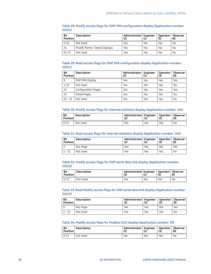
86 GE INFORMATION D20MX HARDWARE USER’S MANUAL
APPENDIX A: DEFAULT ROLE-BASED ACCESS CONTROL MODEL
Table 28: Modify access flags for DNP DPA configuration display (Application number: 32021)
Table 29: Read access flags for DNP DPA configuration display (Application number: 32021)
Table 30: Modify access flags for internet statistics display (Application number: 162)
Table 31: Read access flags for internet statistics display (Application number: 162)
Table 32: Modify access flags for DNP serial data link display (Application number: 32013)
Table 33: Read Modify access flags for DNP serial data link display (Application number: 32013)
Table 34: Modify access flags for Modbus DCA display (Application number: 59)
Bit Position
Description Administrator (2)
Engineer (1)
Operator (3)
Observer (0)
0-23 Not Used Yes Yes Yes No
24 Modify Points / Detail Displays Yes Yes Yes No
25-31 Not Used Yes Yes Yes No
Bit Position
Description Administrator (2)
Engineer (1)
Operator (3)
Observer (0)
0 DNP DPA Display Yes Yes Yes Yes
1-22 Not Used Yes Yes Yes No
23 Configuration Pages Yes Yes Yes Yes
24 Detail Pages Yes Yes Yes No
25 - 31 Not Used Yes Yes Yes No
Bit Position
Description Administrator (2)
Engineer (1)
Operator (3)
Observer (0)
0-31 Not Used Yes Yes Yes No
Bit Position
Description Administrator (2)
Engineer (1)
Operator (3)
Observer (0)
0 Any Page Yes Yes Yes Yes
2 - 31 Not Used Yes Yes Yes No
Bit Position
Description Administrator (2)
Engineer (1)
Operator (3)
Observer (0)
0-31 Not Used Yes Yes Yes No
Bit Position
Description Administrator (2)
Engineer (1)
Operator (3)
Observer (0)
0 Any Page Yes Yes Yes Yes
2 - 31 Not Used Yes Yes Yes No
Bit Position
Description Administrator (2)
Engineer (1)
Operator (3)
Observer (0)
0-31 Not Used Yes Yes Yes No
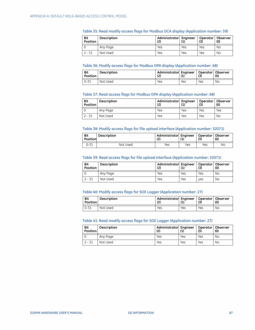
APPENDIX A: DEFAULT ROLE-BASED ACCESS CONTROL MODEL
D20MX HARDWARE USER’S MANUAL GE INFORMATION 87
Table 35: Read modify access flags for Modbus DCA display (Application number: 59)
Table 36: Modify access flags for Modbus DPA display (Application number: 68)
Table 37: Read access flags for Modbus DPA display (Application number: 68)
Table 38: Modify access flags for file upload interface (Application number: 32071)
Table 39: Read access flags for file upload interface (Application number: 32071)
Table 40: Modify access flags for SOE Logger (Application number: 27)
Table 41: Read modify access flags for SOE Logger (Application number: 27)
Bit Position
Description Administrator (2)
Engineer (1)
Operator (3)
Observer (0)
0 Any Page Yes Yes Yes No
2 - 31 Not Used Yes Yes Yes No
Bit Position
Description Administrator (2)
Engineer (1)
Operator (3)
Observer (0)
0-31 Not Used Yes Yes Yes No
Bit Position
Description Administrator (2)
Engineer (1)
Operator (3)
Observer (0)
0 Any Page Yes Yes Yes Yes
2 - 31 Not Used Yes Yes Yes No
Bit Position
Description Administrator (2)
Engineer (1)
Operator (3)
Observer (0)
0-31 Not Used Yes Yes Yes No
Bit Position
Description Administrator (2)
Engineer (1)
Operator (3)
Observer (0)
0 Any Page Yes Yes Yes No
2 - 31 Not Used Yes Yes yes No
Bit Position
Description Administrator (2)
Engineer (1)
Operator (3)
Observer (0)
0-31 Not Used Yes Yes Yes No
Bit Position
Description Administrator (2)
Engineer (1)
Operator (3)
Observer (0)
0 Any Page Yes Yes Yes No
2 - 31 Not Used Yes Yes Yes No

88 GE INFORMATION D20MX HARDWARE USER’S MANUAL
APPENDIX A: DEFAULT ROLE-BASED ACCESS CONTROL MODEL
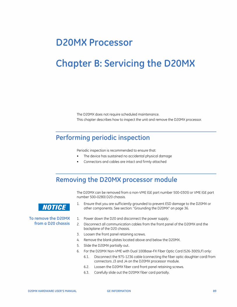
D20MX HARDWARE USER’S MANUAL GE INFORMATION 89
D20MX Processor
Chapter B: Servicing the D20MX
Servicing the D20MX
The D20MX does not require scheduled maintenance. This chapter describes how to inspect the unit and remove the D20MX processor.
Performing periodic inspection
Periodic inspection is recommended to ensure that:
• The device has sustained no accidental physical damage
• Connectors and cables are intact and firmly attached
Removing the D20MX processor module
The D20MX can be removed from a non-VME (GE part number 500-0305) or VME (GE part number 500-0280) D20 chassis.
1. Ensure that you are sufficiently grounded to prevent ESD damage to the D20MX or other components. See section: “Grounding the D20MX” on page 36.
To remove the D20MX from a D20 chassis
1. Power down the D20 and disconnect the power supply.
2. Disconnect all communication cables from the front panel of the D20MX and the backplane of the D20 chassis.
3. Loosen the front panel retaining screws.
4. Remove the blank plates located above and below the D20MX.
5. Slide the D20MX partially out.
6. For the D20MX Non-VME with Dual 100Base-FX Fiber Optic Card (526-3005LF) only:
6.1. Disconnect the 975-1236 cable (connecting the fiber optic daughter card) from connectors J3 and J4 on the D20MX processor module.
6.2. Loosen the D20MX fiber card front panel retaining screws.
6.3. Carefully slide out the D20MX fiber card partially.
90 GE INFORMATION D20MX HARDWARE USER’S MANUAL
CHAPTER B: SERVICING THE D20MX
6.4. Remove the 975-1236 cable through the middle slot in the chassis.
6.5. Store the D20MX fiber card in static-protective packaging.
7. Grasp the D20MX by the front handles and slide the processor module all the way out of the D20 chassis.
Allow the D20MX to cool before removing. The heatsink of the D20MX may be extremely hot during and immediately after operation. Use caution when removing the processor module from the chassis to avoid being burned.
8. Store the D20MX in static-protective packaging.

D20MX HARDWARE USER’S MANUAL GE INFORMATION 91
D20MX Processor
Appendix B: Standards & Protection
Standards & Protection
This Appendix lists the standards with which the D20MX has been tested for compliance.
Compliance standards
Compliance standards are listed for the following categories:
• Emission standards; see Table 42
• Immunity standards; see Table 43
• Safety publications; see Table 44
• Environmental standards; see Table 45
Table 42: Emission standards
Table 43: Immunity standards
Standard Name Description Test Specification
EN55011 (CISPR 11)1 ISM RF equipment – Electromagnetic disturbance characteristics
Radiated Emissions 30 MHz to 1 GHzConducted Emissions 150 kHz – 30 MHz
Standard Name Description Test Specification
IEC 61000-4-2 Electrostatic discharge (ESD) immunity test
Contact Discharge: 8 kVAir Discharge: 15 kVHCP and VCP: 8 kV
IEC 61000-4-3 IEC 61850-3: clause 5.7.2
Radiated, radio-frequency electromagnetic field immunity test
80 MHz to 1 GHz: 10V/m1.4 GHz to 2 GHz: 3V/m2 GHz to 3 GHz: 1V/m
IEC 61000-4-4 IEC 61850-3: clause 5.7.1.4
Electrical fast transient/burst immunity test
Direct Couple: 4 kV/5 kHzCapacitive Clamp: 2 kV/5 kHz
IEC 61000-4-5 Surge immunity test
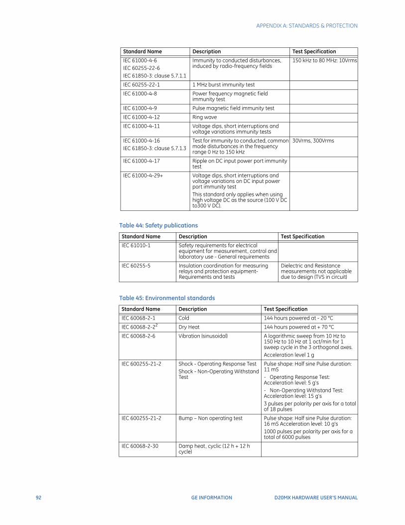
92 GE INFORMATION D20MX HARDWARE USER’S MANUAL
APPENDIX A: STANDARDS & PROTECTION
Table 44: Safety publications
Table 45: Environmental standards
IEC 61000-4-6IEC 60255-22-6IEC 61850-3: clause 5.7.1.1
Immunity to conducted disturbances, induced by radio-frequency fields
150 kHz to 80 MHz: 10Vrms
IEC 60255-22-1 1 MHz burst immunity test
IEC 61000-4-8 Power frequency magnetic field immunity test
IEC 61000-4-9 Pulse magnetic field immunity test
IEC 61000-4-12 Ring wave
IEC 61000-4-11 Voltage dips, short interruptions and voltage variations immunity tests
IEC 61000-4-16IEC 61850-3: clause 5.7.1.3
Test for immunity to conducted, common mode disturbances in the frequency range 0 Hz to 150 kHz
30Vrms, 300Vrms
IEC 61000-4-17 Ripple on DC input power port immunity test
IEC 61000-4-29+ Voltage dips, short interruptions and voltage variations on DC input power port immunity test This standard only applies when using high voltage DC as the source (100 V DC to300 V DC).
Standard Name Description Test Specification
IEC 61010-1 Safety requirements for electrical equipment for measurement, control and laboratory use - General requirements
IEC 60255-5 Insulation coordination for measuring relays and protection equipment- Requirements and tests
Dielectric and Resistance measurements not applicable due to design (TVS in circuit)
Standard Name Description Test Specification
IEC 60068-2-1 Cold 144 hours powered at - 20 °C
IEC 60068-2-22 Dry Heat 144 hours powered at + 70 °C
IEC 60068-2-6 Vibration (sinusoidal) A logarithmic sweep from 10 Hz to 150 Hz to 10 Hz at 1 oct/min for 1 sweep cycle in the 3 orthogonal axes.Acceleration level 1 g
IEC 600255-21-2 Shock - Operating Response TestShock - Non-Operating Withstand Test
Pulse shape: Half sine Pulse duration: 11 mS- Operating Response Test: Acceleration level: 5 g's- Non-Operating Withstand Test: Acceleration level: 15 g's3 pulses per polarity per axis for a total of 18 pulses
IEC 600255-21-2 Bump – Non operating test Pulse shape: Half sine Pulse duration: 16 mS Acceleration level: 10 g's1000 pulses per polarity per axis for a total of 6000 pulses
IEC 60068-2-30 Damp heat, cyclic (12 h + 12 h cycle)
Standard Name Description Test Specification
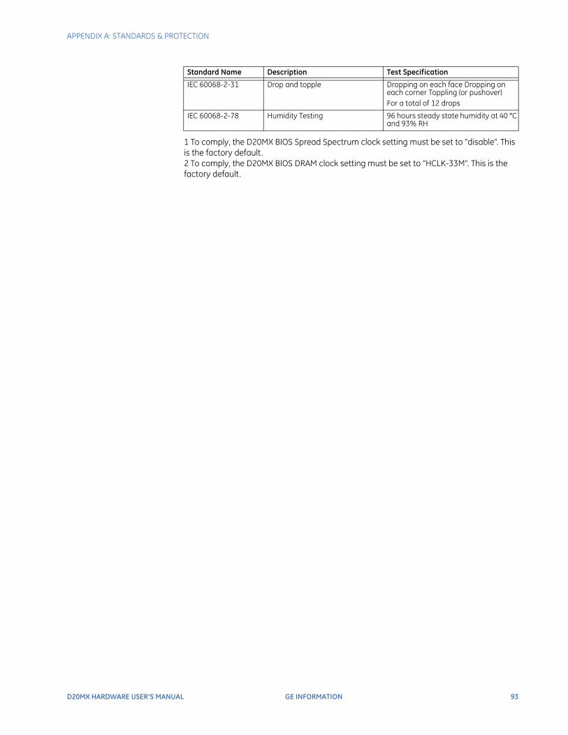
APPENDIX A: STANDARDS & PROTECTION
D20MX HARDWARE USER’S MANUAL GE INFORMATION 93
1 To comply, the D20MX BIOS Spread Spectrum clock setting must be set to “disable”. This is the factory default.2 To comply, the D20MX BIOS DRAM clock setting must be set to “HCLK-33M”. This is the factory default.
IEC 60068-2-31 Drop and topple Dropping on each face Dropping on each corner Toppling (or pushover)For a total of 12 drops
IEC 60068-2-78 Humidity Testing 96 hours steady state humidity at 40 °C and 93% RH
Standard Name Description Test Specification

94 GE INFORMATION D20MX HARDWARE USER’S MANUAL
APPENDIX A: STANDARDS & PROTECTION
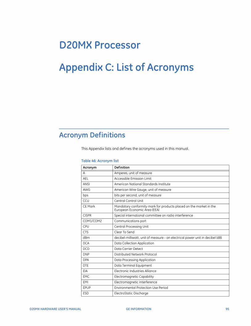
D20MX HARDWARE USER’S MANUAL GE INFORMATION 95
D20MX Processor
Appendix C: List of Acronyms
List of Acronyms
Acronym Definitions
This Appendix lists and defines the acronyms used in this manual.
Table 46: Acronym list
Acronym Definition
A Amperes, unit of measure
AEL Accessible Emission Limit
ANSI American National Standards Institute
AWG American Wire Gauge, unit of measure
bps bits per second, unit of measure
CCU Central Control Unit
CE Mark Mandatory conformity mark for products placed on the market in the European Economic Area (EEA)
CISPR Special international committee on radio interference
COM1/COM2 Communications port
CPU Central Processing Unit
CTS Clear To Send
dBm decibel-milliwatt, unit of measure - an electrical power unit in decibel (dB)
DCA Data Collection Application
DCD Data Carrier Detect
DNP Distributed Network Protocol
DPA Data Processing Application
DTE Data Terminal Equipment
EIA Electronic Industries Alliance
EMC Electromagnetic Capability
EMI Electromagnetic Interference
EPUP Environmental Protection Use Period
ESD ElectroStatic Discharge
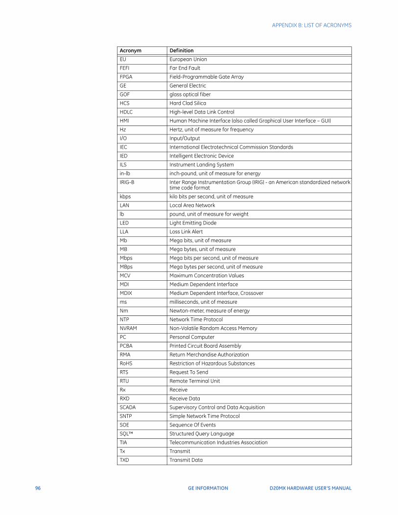
96 GE INFORMATION D20MX HARDWARE USER’S MANUAL
APPENDIX B: LIST OF ACRONYMS
EU European Union
FEFI Far End Fault
FPGA Field-Programmable Gate Array
GE General Electric
GOF glass optical fiber
HCS Hard Clad Silica
HDLC High-level Data Link Control
HMI Human Machine Interface (also called Graphical User Interface – GUI)
Hz Hertz, unit of measure for frequency
I/O Input/Output
IEC International Electrotechnical Commission Standards
IED Intelligent Electronic Device
ILS Instrument Landing System
in-lb inch-pound, unit of measure for energy
IRIG-B Inter Range Instrumentation Group (IRIG) - an American standardized network time code format
kbps kilo bits per second, unit of measure
LAN Local Area Network
lb pound, unit of measure for weight
LED Light Emitting Diode
LLA Loss Link Alert
Mb Mega bits, unit of measure
MB Mega bytes, unit of measure
Mbps Mega bits per second, unit of measure
MBps Mega bytes per second, unit of measure
MCV Maximum Concentration Values
MDI Medium Dependent Interface
MDIX Medium Dependent Interface, Crossover
ms milliseconds, unit of measure
Nm Newton-meter, measure of energy
NTP Network Time Protocol
NVRAM Non-Volatile Random Access Memory
PC Personal Computer
PCBA Printed Circuit Board Assembly
RMA Return Merchandise Authorization
RoHS Restriction of Hazardous Substances
RTS Request To Send
RTU Remote Terminal Unit
Rx Receive
RXD Receive Data
SCADA Supervisory Control and Data Acquisition
SNTP Simple Network Time Protocol
SOE Sequence Of Events
SQL™ Structured Query Language
TIA Telecommunication Industries Association
Tx Transmit
TXD Transmit Data
Acronym Definition

APPENDIX B: LIST OF ACRONYMS
D20MX HARDWARE USER’S MANUAL GE INFORMATION 97
UART Universal Asynchronous Receiver-Transmitter
UTP Unshielded Twisted Pair
VA Volt Amps, unit of measure
V AC Volts, Alternating Current, unit of measure
V DC Volts, Direct Current, unit of measure
VME Versa Module Eurocard
Acronym Definition

98 GE INFORMATION D20MX HARDWARE USER’S MANUAL
APPENDIX B: LIST OF ACRONYMS
D20MX HARDWARE USER’S MANUAL GENERAL 99
D20MX Processor
Index
AAUTOMATIC ON-LINE STARTUP TEST ............................................ 55AUTOMATION APPLICATIONS ............................................................ 16
CCABLING
D.20 Link .................................................................................................... 41Ethernet ..................................................................................................... 42fiber optic ................................................................................................. 43overview .................................................................................................... 39serial ........................................................................................................... 41
CHASSIS OVERVIEWD20 non-VME .......................................................................................... 18D20 VME .................................................................................................... 20
CODE FILES .................................................................................................. 56COMMUNICATIONS SPECIFICATIONS ............................................ 25COMPLIANCE STANDARDS AND PROTECTION ......................... 91CONFIGURATION FILES ......................................................................... 56CONFIGURATIONS
transfer D20/D200 ............................................................................... 69update D20/D200 ................................................................................. 77
CONNECT THE POWER SUPPLY ........................................................ 36CUSTOMER SUPPORT .............................................................................11
DD.20 LINK CABLING ................................................................................. 41D20
chassis overview ................................................................................... 18modems .................................................................................................... 22peripherals ............................................................................................... 22power supplies ....................................................................................... 21system redundancy .............................................................................47
D20 CHASSIS LAYOUTS ......................................................................... 29D20 NON-VME CHASSIS OVERVIEW .............................................. 18
D20 VME CHASSIS OVERVIEW ...........................................................20D20MX
connect the power supply ................................................................36grounding .................................................................................................36installation steps ...................................................................................31removal steps .........................................................................................89retrofit .........................................................................................................33unpacking .................................................................................................36
D20MX PROCESSOR ................................................................................15DEFAULT USER ...........................................................................................60DESIGN OF PRODUCT .............................................................................15DOCUMENTATION
additional .................................................................................................... 7audience ...................................................................................................... 7conventions ............................................................................................... 8
DOWNLOADsoftware over network .......................................................................64software over serial .............................................................................61when ...........................................................................................................61
EECCN NUMBER ...........................................................................................15ELECTRIC SPECIFICATIONS ..................................................................25ENVIRONMENT SPECIFICATIONS .....................................................26ETHERNET
cabling ........................................................................................................42fiber optic ..................................................................................................43twisted-pair ..............................................................................................42
FFAIL-OVER CHECK ....................................................................................57FIBER OPTIC
cabling ........................................................................................................43port LEDs ...................................................................................................82
FILES
100 GENERAL D20MX HARDWARE USER’S MANUAL
INDEX
code ............................................................................................................56configuration ..........................................................................................56
FIRMWAREupgrade .....................................................................................................12versions .....................................................................................................65
FIRMWAREoptions .......................................................................................................66
FIRMWARE/FPGA VERSIONS ..............................................................18FRONT PANEL LEDS ................................................................................81
GGROUNDING D20MX ..............................................................................36
IIMAGE DOWNLOAD PREREQUISITES .............................................61INSTALLATION STEPS .............................................................................31INTRODUCTION TO SOFTWARE ........................................................59IP ADDRESSES ............................................................................................44
KKITS ..................................................................................................................24
LLAN PORT LEDS .........................................................................................82LAN REDUNDANCY ..................................................................................44LEDS
fiber optic port status .........................................................................82front panel ................................................................................................81LAN port status ......................................................................................82operational status ................................................................................81
LOCAL USER ACCOUNTS ......................................................................60
MMANUAL - HOW TO USE ..........................................................................8MATERIALS - REQUIRED ........................................................................35MIGRATE D20MX APPLICATION DEFINITIONS TO SGCONFIG
69MODEMS .......................................................................................................22
NNUMBER - ECCN .......................................................................................15
OOPERATIONAL LEDS ................................................................................81OVERVIEW
cabling .......................................................................................................39D20 chassis ..............................................................................................18
D20MX processor ..................................................................................15product .......................................................................................................15
PPACKAGE CONTENTS ..............................................................................36PERIODIC INSPECTION ...........................................................................89PERIPHERALS ..............................................................................................22PHYSICAL SPECIFICATIONS .................................................................26PORT - RS-232 ............................................................................................47POWER SUPPLIES .....................................................................................21POWER-UP ...................................................................................................55POWER-UP AND TEST REQUIREMENTS ........................................53POWER-UP AND TEST STEPS ..............................................................54PRECAUTIONS
safety ..........................................................................................................13warning symbols ...................................................................................14
PREREQUISITES FOR IMAGE DOWNLOAD ...................................61PRODUCT
overview ....................................................................................................15return ..........................................................................................................12specifications ..........................................................................................25
PRODUCT DESIGN ....................................................................................15
RRECOMMENDATIONS
storage .......................................................................................................27storage conditions ................................................................................27
RECOVERY MODE USER ACCOUNT .................................................60REDUNDANCY
LAN ...............................................................................................................44system ........................................................................................................47system - test ............................................................................................56
REGULATORY COMPLIANCE ................................................................14CE mark ......................................................................................................14
REMOTE USER ACCOUNTS ...................................................................60REMOVAL - D20MX ..................................................................................89REQUIRED
materials ...................................................................................................35tools .............................................................................................................35
REQUIREMENTS - TESTING ..................................................................53RETROFIT D20MX ......................................................................................33RETURN PRODUCT ...................................................................................12RS-232 PORT ...............................................................................................47
SSAFETY PRECAUTIONS ...........................................................................13SECURITY .......................................................................................................16SERIAL CABLING ........................................................................................41SGCONFIG
Migrate D20MX Application Definitions ......................................69SHELL ..............................................................................................................54SOFTWARE
download over network .....................................................................64
INDEX
D20MX HARDWARE USER’S MANUAL GENERAL 101
download over serial .......................................................................... 61introduction ............................................................................................. 59specifications .......................................................................................... 26Tera Term set up ................................................................................... 61when to download ............................................................................... 61
SOFTWARE APPLICATIONS .................................................................. 16SOFTWARE PREREQUISITES ............................................................... 61SPECIFICATIONS
communications ................................................................................... 25electric ....................................................................................................... 25environment ............................................................................................ 26physical ..................................................................................................... 26product ...................................................................................................... 25software .................................................................................................... 26system ........................................................................................................ 25
STANDARDS AND PROTECTION COMPLIANCE ......................... 91STORAGE
conditions ................................................................................................. 27recommendations ................................................................................27
SUPPORTcustomer ................................................................................................... 11technical ................................................................................................... 11
SWITCH-OVERcheck .......................................................................................................... 57verify hardware or software ............................................................ 58
SYSTEMredundancy ............................................................................................. 47specifications .......................................................................................... 25
TTECHNICAL SUPPORT .............................................................................11TERA TERM SET UP .................................................................................. 61TERMINAL
emulation ................................................................................................. 54WESMAINT II+ ..................................................................................54, 55
TERMINAL EMULATOR ........................................................................... 61TEST
automatic on-line startup ................................................................ 55fail-over ..................................................................................................... 57requirements .......................................................................................... 53switch-over .............................................................................................. 57system redundancy .............................................................................56
TOOLS - REQUIRED .................................................................................. 35TRANSFER D20/D200 CONFIGURATIONS ................................... 69TWISTED-PAIR ............................................................................................ 42
UUNPACKING THE D20MX ..................................................................... 36UPDATE D20/D200 CONFIGURATIONS ........................................ 77UPDATE FIRMWARE OPTIONS ........................................................... 66UPGRADE FIRMWARE ............................................................................ 12UPGRADE KITS ........................................................................................... 24USER ACCOUNTS
local ............................................................................................................. 60recovery .................................................................................................... 60
remote ........................................................................................................60
VVERSIONS
firmware ....................................................................................................18FPGA ............................................................................................................18
VERSIONS OF FIRMWARE .....................................................................65
WWARNING SYMBOLS ...............................................................................14WESMAINT II+ ..................................................................................... 54, 55

102 GENERAL D20MX HARDWARE USER’S MANUAL
INDEX
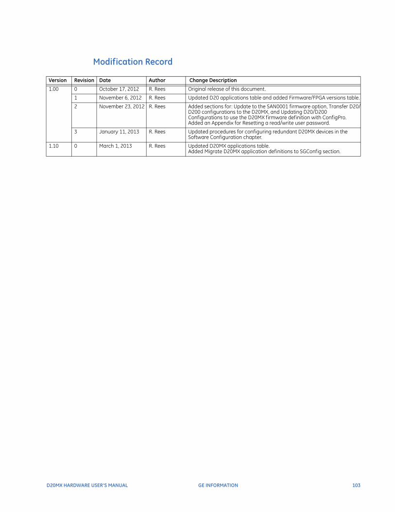
D20MX HARDWARE USER’S MANUAL GE INFORMATION 103
Modification Record
Version Revision Date Author Change Description
1.00 0 October 17, 2012 R. Rees Original release of this document.
1 November 6, 2012 R. Rees Updated D20 applications table and added Firmware/FPGA versions table.
2 November 23, 2012 R. Rees Added sections for: Update to the SAN0001 firmware option, Transfer D20/D200 configurations to the D20MX, and Updating D20/D200 Configurations to use the D20MX firmware definition with ConfigPro.Added an Appendix for Resetting a read/write user password.
3 January 11, 2013 R. Rees Updated procedures for configuring redundant D20MX devices in the Software Configuration chapter.
1.10 0 March 1, 2013 R. Rees Updated D20MX applications table.Added Migrate D20MX application definitions to SGConfig section.

104 GE INFORMATION D20MX HARDWARE USER’S MANUAL