Embed Size (px)
Citation preview

937
Related InformationFIBERSENSORS
LASERSENSORS
PHOTOELECTRICSENSORS
MICROPHOTOELECTRIC
SENSORS
AREASENSORS
SAFETY LIGHT CURTAINS /
SAFETY COMPONENTSPRESSURE /
FLOWSENSORS
INDUCTIVEPROXIMITY
SENSORS
PARTICULARUSE SENSORS
SENSOROPTIONS
SIMPLEWIRE-SAVING
UNITS
WIRE-SAVING SYSTEMS
MEASUREMENTSENSORS
STATIC CONTROL DEVICES
LASERMARKERS
PLC
HUMAN MACHINE INTERFACES
ENERGY MANAGEMENT
SOLUTIONS
FA COMPONENTS
MACHINE VISION SYSTEMS
UV CURING SYSTEMS
Selection Guide
Liquid Leak Detection
Liquid Level Detection
Water Detection
Color Mark Detection
Wafer Detection
Ultrasonic
Small / Slim Object Detection
Obstacle Detection
PX-2
Ideal sensing area with very little null zoneThe advanced optical system of the PX-2 series reduces the null zones in front of an automatic guided vehicle (AGV).The null zones at the sides are further minimized if auxiliary sensors which can be easily mounted with connectors are used.
Auxiliary sensor (Optional) Auxiliary left OUT 1 area (700 mm 27.559 in)
Adjacent left OUT 1 area
OUT 1 area: 3 m 9.843 ft 1 m 3.281 ft with PX-21 and PX-23ES, 5 m 16.404 ft with PX-26
OUT 2 area: 3 m 9.843 ft 1 m 3.281 ft with PX-21 and PX-23ES, 5 m 16.404 ft with PX-26
Auxiliary sensor (Optional) Auxiliary right OUT 1 area (700 mm 27.559 in)
Adjacent right OUT 1 area
( ) ( )For PX-24, PX-24ES, PX-23ES and PX-26
PX-2 SERIES
Compact size sensor realizes wide sensingarea & long sensing range
Compact size for space-savingIts size is half of a conventional model,and the attached cable orientation is freely adjustable. Hence, it can also fit in a small AGV.Moreover, sensitivity adjustment can be done on the front face.
Long sensing range 5 m 16.404 ft typePX-26 has a long sensing range of 5 m 16.404 ft. Even on a high-speed AGV, it can detect an object quite early so that slowing down and stopping are smooth.
Automatic interference prevention functionOne PX-2 sensor can simultaneously receive beams from 25 Nos. of other PX-2 sensors without resulting in any interference. Even if AGVs are facing each other, the PX-2 sensor on one AGV reliably detects the other AGVs.Hence, it can be safely used even at a place where several AGVs are moving.
43 mm1.693 in
83 mm3.268 in62 mm
2.441 in
Sensitivity adjuster
Sleep functionThe sensor can be put into the sleep (stand-by) condition when it is not used and can be restored to operating condition by an external signal.Consequently battery is conserved as the power consumption is reduced to 1/5.
External sensitivity adjustmentThe sensitivity of the sensor can be adjusted, within the range set by the manual adjuster, by an external input. (For PX-24, PX-24ES, PX-23ES and PX-26)
Sensing areas selectable as per route conditionSensing areas can be selected with switches to suit the route conditions of an AGV.Further, in case of PX-24ES and PX-23ES, the sensing areas can also be selected with external signals.
Long Range & Wide Area Photoelectric Sensor
General terms and conditions ............. F-3 Selection guide ............................. P.865~
Glossary of terms........................ P.1549~ General precautions .................... P.1552~
panasonic.net/id/pidsx/global

Long Range & Wide Area Photoelectric Sensor PX-2 SERIES 938
FIBERSENSORS
LASERSENSORS
PHOTO-ELECTRICSENSORSMICROPHOTO-ELECTRICSENSORS
AREASENSORS
SAFETY LIGHT CURTAINS /SAFETY COMPONENTSPRESSURE / FLOWSENSORS
INDUCTIVEPROXIMITYSENSORS
PARTICULARUSE SENSORS
SENSOROPTIONS
SIMPLEWIRE-SAVINGUNITS
WIRE-SAVING SYSTEMS
MEASURE-MENTSENSORS
STATIC CONTROL DEVICES
LASERMARKERS
PLC
HUMAN MACHINE INTERFACES
ENERGY MANAGEMENT SOLUTIONS
FA COMPONENTS
MACHINE VISION SYSTEMS
UV CURING SYSTEMS
Selection GuideLiquid Leak DetectionLiquid Level DetectionWater DetectionColor Mark DetectionWafer Detection
Ultrasonic
Small / Slim Object DetectionObstacle Detection
PX-2
ORDER GUIDE
Main Sensor
Type Appearance Sensing range Model No.
Sta
ndar
d ty
pe 3 m 9.843 ft PX-22
Short
sensi
ng ra
nge
1 m 3.281 ft PX-21
Aux
iliar
y se
nsor
con
nect
able
type
3 m 9.843 ft
PX-24
With
ext
erna
l con
trol f
unct
ion
PX-24ES
Short
sensi
ng ra
nge
1 m 3.281 ft PX-23ES
Long
se
nsin
g ra
nge 5 m 16.404 ft PX-26
Auxiliary sensor 700 mm 27.559 in PX-SB1
Accessories• MS-PX-2 (Main sensor mounting bracket) • MS-NX5-1 (Auxiliary sensor mounting bracket)
Two bracket set Four M4 (length 8 mm 0.315 in) screws with washers are attached.
Two M4 (length 25 mm 0.984 in) screws with washers and two M4 nuts are attached.
OPTIONS
Designation Model No. Description
Auxiliary sensor mounting bracket
MS-NX5-2 Foot biangled mounting bracket (Sensor protection bracket)
MS-NX5-3 Back angled mounting bracket
Auxiliary sensor mounting bracket• MS-NX5-2 • MS-NX5-3
Two M4 (length 25 mm0.984 in) screws withwashers and two M4 nutsare attached.
Two M4 (length 25 mm0.984 in) screws withwashers and two M4 nutsare attached.

939 Long Range & Wide Area Photoelectric Sensor PX-2 SERIES
FIBERSENSORS
LASERSENSORS
PHOTO-ELECTRICSENSORS
MICROPHOTO-
ELECTRICSENSORS
AREASENSORS
SAFETY LIGHT CURTAINS /
SAFETY COMPONENTSPRESSURE /
FLOWSENSORS
INDUCTIVEPROXIMITY
SENSORS
PARTICULARUSE
SENSORS
SENSOROPTIONS
SIMPLEWIRE-SAVING
UNITS
WIRE-SAVING SYSTEMS
MEASURE-MENT
SENSORS
STATIC CONTROL DEVICES
LASERMARKERS
PLC
HUMAN MACHINE
INTERFACES
ENERGY MANAGEMENT
SOLUTIONS
FA COMPONENTS
MACHINE VISION
SYSTEMS
UV CURING
SYSTEMS
Selection Guide
Liquid Leak Detection
Liquid Level Detection
Water DetectionColor Mark
DetectionWafer
Detection
Ultrasonic
Small / Slim Object DetectionObstacle Detection
PX-2
SPECIFICATIONS
Main sensors
TypeStandard model
Auxiliary sensor connectable model
With external control function Long sensing rangeShort sensing range Short sensing range
Item Model No. PX-22 PX-21 PX-24 PX-24ES PX-23ES PX-26CE marking directive compliance EMC Directive, RoHS Directive
Sensing range (OUT 1 and OUT 2 areas) (Note 2) 3 m 9.843 ft 1 m 3.281 ft 3 m 9.843 ft 1 m 3.281 ft 5 m 16.404 ft
Hysteresis (Note 2) 15 % or less of operation distance
Supply voltage 10 to 31 V DC including ripple
Power consumption (Note 3) Under operation: 1.5 W or less, Under sleep condition: 0.3 W or less (without auxiliary sensor)OUT1
OUT2
NPN open-collector transistor• Maximum sink current: 100 mA• Applied voltage: 40 V DC or less (between OUT 1 / OUT 2 and 0 V)• Residual voltage: 1.5 V or less (at 100 mA sink current)
0.4 V or less (at 16 mA sink current)
Utilization category DC-12 or DC-13
Output operation Selectable either Light-ON or Dark-ON with a switch (Output operation of OUT 1 and OUT 2 is the same.)
Short-circuit protection Incorporated
Extraneous light monitor output
–
NPN open-collector transistor• Maximum sink current: 100 mA• Applied voltage: 40 V DC or less (between extraneous light monitor output and 0 V)• Residual voltage: 1.5 V or less (at 100 mA sink current)
0.4 V or less (at 16 mA sink current)
Output operation – ON when modulated beam other than its own (including auxiliary sensor’s) light is received
Short-circuit protection – –
Response time 80 ms or less
Operationindicators
OUT 1 area Red LED (lights up when the beam is received in the effective OUT 1 areas)
OUT 2 area Yellow LED (lights up when the beam is received in the effective OUT 2 areas)
Sensitivity adjuster Continuously variable adjusters (OUT 1, adjacent right OUT 1, adjacent left OUT 1 and OUT 2 areas are adjusted independently.)
External sensitivity adjustment function – Sensitivity adjustment is possible with an analog input.
Sensing area Four sensing areas are selectable with dip switches. Four sensing areas are selectable with dip switches, and eight sensing areas are selectable with external inputs. Fixed
Sleep function Operating / sleep selectable with external input
Automatic interference prevention function Optical interference from up to 25 units is prevented.
Env
ironm
enta
l res
ista
nce
Pollution degree 3 (Industrial environment)
Protection IP65 (IEC)
Ambient temperature –10 to +55 °C +14 to +131 °F (No dew condensation or icing allowed), Storage: –20 to +70 °C –4 to +158 °F
Ambient humidity 35 to 85 % RH, Storage: 35 to 85 % RH
Ambient illuminance Incandescent light: 3,000 ℓx or less at the light-receiving face
Voltage withstandability 1,000 V AC for one min. between all supply terminals connected together and enclosure
Insulation resistance 20 MΩ, or more, with 500 V DC megger between all supply terminals connected together and enclosure
Vibration resistance 10 to 500 Hz frequency, 3 mm 0.118 in double amplitude (20 G max.) in X, Y and Z directions for two hours each
Shock resistance 500 m/s2 acceleration (50 G approx.) in X, Y and Z directions three times each
Emitting element Infrared LED (Peak emission wavelength: 950 nm 0.037 mil, modulated)
Material Enclosure: ABS, Lens: Acrylic, Cover: Polycarbonate
Cable 0.3 mm2 5-core cabtyre cable, 0.5 m 1.640 ft long (for input and output)
For input and output: 0.18 mm2 9-core (PX-24ES and PX-23ES: 12-core) cabtyre cable, 0.5 m 1.640 ft longFor auxiliary sensor connection: 0.18 mm2 10-core connector attached cabtyre cable, 0.5 m 1.640 ft long
Cable extension Extension up to total 100 m 328.084 ft (10 m 32.808 ft for auxiliary sensor connection) is possible with 0.3 mm2, or more, cable.
Weight Net weight: 210 g approx.Gross weight: 390 g approx.
Net weight: 220 g approx. Gross weight: 400 g approx.
Net weight: 210 g approx. Gross weight: 390 g approx.
Accessories MS-PX-2 (Main sensor mounting bracket): 1 set, Adjusting screwdriver: 1 pc., Matrix chart for sensing areas and external inputs: 1 sheet (PX-24ES and PX-23ES only)
OR circuit among the effective center, left, right, adjacent left / right OUT 1 areas and the effective auxiliary left / right areas
OR circuit among the effective center, left and right OUT 2 areas
Notes: 1) Where measurement conditions have not been specified precisely, the conditions used were an ambient temperature of +23 °C +73.4 °F.2) The sensing range is specified for white non-glossy paper (300 × 300 mm 11.811 × 11.811 in) as the object.3) Obtain the current consumption by the following calculation.
Current consumption = Power consumption ÷ Supply voltage (e.g.) When the supply voltage is 12 V, the current consumption (operating condition) is: 1.5 W ÷ 12 V = 0.125 A = 125 mA
Long Range & Wide Area Photoelectric Sensor PX-2 SERIES 940
FIBERSENSORS
LASERSENSORS
PHOTO-ELECTRICSENSORSMICROPHOTO-ELECTRICSENSORS
AREASENSORS
SAFETY LIGHT CURTAINS /SAFETY COMPONENTSPRESSURE / FLOWSENSORS
INDUCTIVEPROXIMITYSENSORS
PARTICULARUSE SENSORS
SENSOROPTIONS
SIMPLEWIRE-SAVINGUNITS
WIRE-SAVING SYSTEMS
MEASURE-MENTSENSORS
STATIC CONTROL DEVICES
LASERMARKERS
PLC
HUMAN MACHINE INTERFACES
ENERGY MANAGEMENT SOLUTIONS
FA COMPONENTS
MACHINE VISION SYSTEMS
UV CURING SYSTEMS
Selection GuideLiquid Leak DetectionLiquid Level DetectionWater DetectionColor Mark DetectionWafer Detection
Ultrasonic
Small / Slim Object DetectionObstacle Detection
PX-2
*1
For auxiliary sensor connection
0 to +5 V DC
Load
Load
Load
Brown
Blue
White
Pink
Pink / Black
Pink / White
Pink / Violet
Violet
Violet / Black
Pink / Gray
Black / White
Black
+ -
+ - 10 to 31 V DC
SPECIFICATIONS
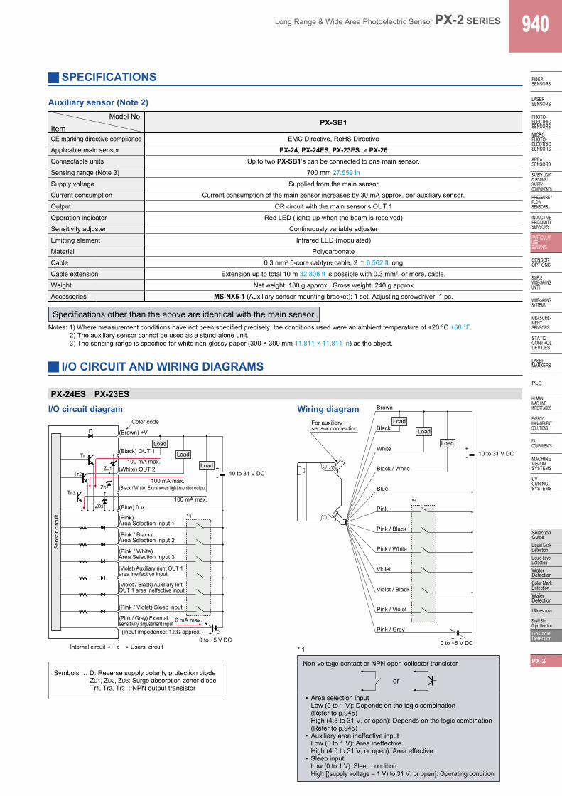
Auxiliary sensor (Note 2)
ItemModel No.
PX-SB1
CE marking directive compliance EMC Directive, RoHS Directive
Applicable main sensor PX-24, PX-24ES, PX-23ES or PX-26Connectable units Up to two PX-SB1’s can be connected to one main sensor.
Sensing range (Note 3) 700 mm 27.559 in
Supply voltage Supplied from the main sensor
Current consumption Current consumption of the main sensor increases by 30 mA approx. per auxiliary sensor.
Output OR circuit with the main sensor’s OUT 1
Operation indicator Red LED (lights up when the beam is received)
Sensitivity adjuster Continuously variable adjuster
Emitting element Infrared LED (modulated)
Material Polycarbonate
Cable 0.3 mm2 5-core cabtyre cable, 2 m 6.562 ft long
Cable extension Extension up to total 10 m 32.808 ft is possible with 0.3 mm2, or more, cable.
Weight Net weight: 130 g approx., Gross weight: 240 g approx
Accessories MS-NX5-1 (Auxiliary sensor mounting bracket): 1 set, Adjusting screwdriver: 1 pc.
Notes: 1) Where measurement conditions have not been specified precisely, the conditions used were an ambient temperature of +20 °C +68 °F.2) The auxiliary sensor cannot be used as a stand-alone unit.3) The sensing range is specified for white non-glossy paper (300 × 300 mm 11.811 × 11.811 in) as the object.
Specifications other than the above are identical with the main sensor.
I/O CIRCUIT AND WIRING DIAGRAMS
PX-24ES PX-23ES
I/O circuit diagram Wiring diagram
* 1
Non-voltage contact or NPN open-collector transistor
or
• Area selection inputLow (0 to 1 V): Depends on the logic combination (Refer to p.945)High (4.5 to 31 V, or open): Depends on the logic combination (Refer to p.945)
• Auxiliary area ineffective inputLow (0 to 1 V): Area ineffectiveHigh (4.5 to 31 V, or open): Area effective
• Sleep inputLow (0 to 1 V): Sleep conditionHigh [(supply voltage – 1 V) to 31 V, or open]: Operating condition
Users’ circuit Internal circuit
Sen
sor c
ircui
t
D (Brown) +V
100 mA max.
Load
Z D2
Z D1
Z D3 (Blue) 0 V
0 to +5 V DC + -
100 mA max.
100 mA max.
6 mA max.
Color code
*1
Tr 3
Tr 2
Tr 1
(White) OUT 2
(Pink) Area Selection Input 1
(Pink / Black) Area Selection Input 2
(Pink / White) Area Selection Input 3
(Pink / Violet) Sleep input
(Violet) Auxiliary right OUT 1 area ineffective input
(Violet / Black) Auxiliary left OUT 1 area ineffective input
(Pink / Gray) External sensitivity adjustment input
(Black / White) Extraneous light monitor output
(Black) OUT 1 Load
Load
(Input impedance: 1 kΩ approx.)
+ - 10 to 31 V DC
Symbols … D: Reverse supply polarity protection diodeZD1, ZD2, ZD3: Surge absorption zener diodeTr1, Tr2, Tr3 : NPN output transistor
941 Long Range & Wide Area Photoelectric Sensor PX-2 SERIES
FIBERSENSORS
LASERSENSORS
PHOTO-ELECTRICSENSORS
MICROPHOTO-
ELECTRICSENSORS
AREASENSORS
SAFETY LIGHT CURTAINS /
SAFETY COMPONENTSPRESSURE /
FLOWSENSORS
INDUCTIVEPROXIMITY
SENSORS
PARTICULARUSE
SENSORS
SENSOROPTIONS
SIMPLEWIRE-SAVING
UNITS
WIRE-SAVING SYSTEMS
MEASURE-MENT
SENSORS
STATIC CONTROL DEVICES
LASERMARKERS
PLC
HUMAN MACHINE
INTERFACES
ENERGY MANAGEMENT
SOLUTIONS
FA COMPONENTS
MACHINE VISION
SYSTEMS
UV CURING
SYSTEMS
Selection Guide
Liquid Leak Detection
Liquid Level Detection
Water DetectionColor Mark
DetectionWafer
Detection
Ultrasonic
Small / Slim Object DetectionObstacle Detection
PX-2
Sen
sor c
ircui
t
D (Brown) +V
100 mA max. Z D1
Load
Z D2
Load (Black) OUT1
(White) OUT2
(Blue) 0 V
*1
Users’ circuit Internal circuit
100 mA max.
Color code
Tr 1
Tr 2
(Pink / Violet) Sleep input
+ - 10 to 31 V DC
Load
Brown
White
Black Load
Blue
Pink / Violet *1
+ - 10 to 31 V DC
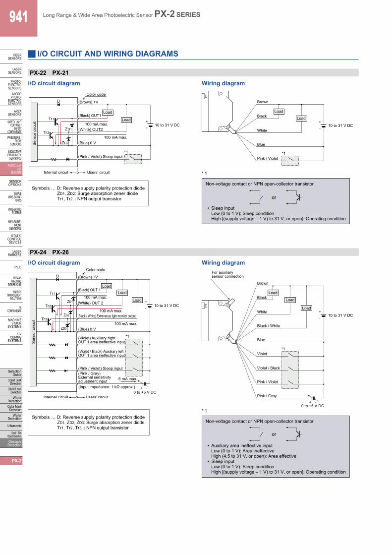
I/O CIRCUIT AND WIRING DIAGRAMS
I/O circuit diagram Wiring diagram
PX-22 PX-21
* 1
Non-voltage contact or NPN open-collector transistor
or
• Sleep inputLow (0 to 1 V): Sleep conditionHigh [(supply voltage – 1 V) to 31 V, or open]: Operating condition
*1
Tr 1
Tr 2
Tr 3
D
100 mA max. Z D1
Z D2
Z D3
100 mA max.
100 mA max.
6 mA max.
Color code
Load Load
Load
(Brown) +V
(White) OUT 2
(Black / White) Extraneous light monitor output
(Black) OUT 1
(Blue) 0 V
(Violet / Black) Auxiliary left OUT 1 area ineffective input
(Pink / Violet) Sleep input (Pink / Gray) External sensitivity adjustment input
Users’ circuit Internal circuit 0 to +5 V DC
Sen
sor c
ircui
t
(Input impedance: 1 kΩ approx.)
(Violet) Auxiliary right OUT 1 area ineffective input
10 to 31 V DC +
+
For auxiliary sensor connection
Load
Load
Load
Brown
Blue
White
Black / White
Black
Violet
Violet / Black
Pink / Gray
Pink / Violet
*1
0 to +5 V DC + -
+ - 10 to 31 V DC
PX-24 PX-26
I/O circuit diagram Wiring diagram
* 1
Non-voltage contact or NPN open-collector transistor
or
• Auxiliary area ineffective inputLow (0 to 1 V): Area ineffectiveHigh (4.5 to 31 V, or open): Area effective
• Sleep inputLow (0 to 1 V): Sleep conditionHigh [(supply voltage – 1 V) to 31 V, or open]: Operating condition
Symbols … D: Reverse supply polarity protection diodeZD1, ZD2: Surge absorption zener diodeTr1, Tr2 : NPN output transistor
Symbols … D: Reverse supply polarity protection diodeZD1, ZD2, ZD3: Surge absorption zener diodeTr1, Tr2, Tr3 : NPN output transistor

Long Range & Wide Area Photoelectric Sensor PX-2 SERIES 942
FIBERSENSORS
LASERSENSORS
PHOTO-ELECTRICSENSORSMICROPHOTO-ELECTRICSENSORS
AREASENSORS
SAFETY LIGHT CURTAINS /SAFETY COMPONENTSPRESSURE / FLOWSENSORS
INDUCTIVEPROXIMITYSENSORS
PARTICULARUSE SENSORS
SENSOROPTIONS
SIMPLEWIRE-SAVINGUNITS
WIRE-SAVING SYSTEMS
MEASURE-MENTSENSORS
STATIC CONTROL DEVICES
LASERMARKERS
PLC
HUMAN MACHINE INTERFACES
ENERGY MANAGEMENT SOLUTIONS
FA COMPONENTS
MACHINE VISION SYSTEMS
UV CURING SYSTEMS
Selection GuideLiquid Leak DetectionLiquid Level DetectionWater DetectionColor Mark DetectionWafer Detection
Ultrasonic
Small / Slim Object DetectionObstacle Detection
PX-2
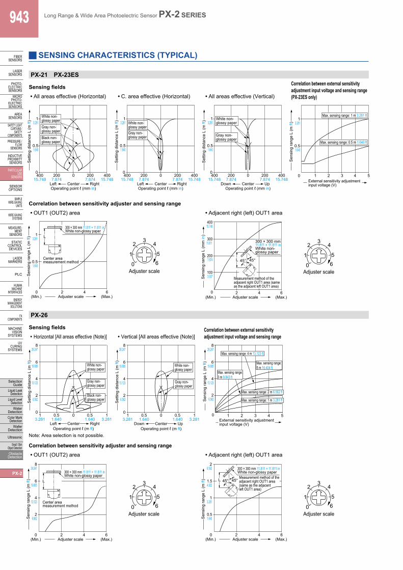
SENSING CHARACTERISTICS (TYPICAL)
How to read sensing characteristics
• Sensing field Sensing area
Note: The sensitivity has been adjusted so that the maximum sensing range for white non-glossy paper (300 × 300 mm 11.811 × 11.811 in) is 3 m 9.843 ft (1 m 3.281 ft for PX-21 and PX-23ES, 5 m 16.404 ft for PX-26) with the L., C. and R. areas effective.
L. : Left areaC. : Center areaR. : Right areaL’. : Adjacent left OUT 1 areaR’. : Adjacent right OUT 1 area
• Correlation between external sensitivity adjustment input voltage and sensing range
Sensing object
Type of non-glossy paper
White non-glossy paper (lightness: 9)
Gray non-glossy paper (lightness: 5)
Black non-glossy paper (lightness: 2)
It shows the variation in the sensing range when the external input voltage is changed from 0 to +5 V with the sensitivity adjuster set at the maximum sensing range.
• Correlation between sensitivity adjuster and sensing rangePlease note that due to the adjuster’s characteristics it may be difficult to adjust the sensitivity at a close distance or near to rated sensing distances. (Refer to “Correlation between sensitivity adjustor and sensing range” below.)
All models
Correlation between setting distance and excess gain
L L
Horizontal (left-right) direction
Vertical (up-down) direction
Non-glossy paper
ℓ ℓ
300 × 300 mm11.811 × 11.811 in L.
C.
R.
L’.
R’.
L
White non-glossy paper
300 × 300 mm11.811 × 11.811 in
0 13.281
39.843
413.123
516.404
1
10
5
100
26.562
Exc
ess
gain
50
PX-SB1
PX-21PX-23ES
PX-22 PX-24PX-24ES
Setting distance L (m ft)
PX-26
PX-22 PX-24 PX-24ES
Sensing fields Correlation between external sensitivity adjustment input voltage and sensing range(Excluding PX-22)• All areas effective (Horizontal) • C. area effective (Horizontal) • All areas effective (Vertical)
Correlation between sensitivity adjuster and sensing range• OUT1(OUT2) area • Adjacent right (left) OUT1 area
0 6
5 1
2 3
Adjuster scale
4
2 0 4 6
1 3.281
2 6.562
4 13.123
3 9.843
Adjuster scale
Sen
sing
rang
e L
(m ft
)
(Min.) (Max.)
Center area measurement method
300 × 300 mm 11.811 × 11.811 ftWhite non-glossy paper
L
0 6
51
2 3
4
300 × 300 mm 11.811 × 11.811 ftWhite non-glossy paper
Adjuster scale
Measurement method of the adjacent right OUT1 area (same as the adjacent left OUT1 area)
4 6
1 3.281
2 0
0.5 1.640
2 6.562
1.5 4.922
L 45° 45°
Adjuster scale (Min.) (Max.)
Sen
sing
rang
e L
(m ft
)
0
White non-glossy paperGray non-
glossy paperBlack non-glossy paper
13.281
0.51.640
0 0.51.640
13.281
Left RightCenterOperating point ℓ (m ft)
13.281
26.562
413.123
39.843
Set
ting
dist
ance
L (m
ft)
0
White non-glossy paper
Gray non-glossy paper
13.281
0.51.640
0 0.51.640
13.281
CenterOperating point ℓ (m ft)
13.281
26.562
413.123
39.843
Left Right
Set
ting
dist
ance
L (m
ft)
13.281
0.51.640
0 0.51.640
13.281
White non-glossy paper
Gray non-glossy paper
Down UpCenterOperating point ℓ (m ft)
13.281
26.562
413.123
39.843
0
Set
ting
dist
ance
L (m
ft)
1 2 3 4 0
13.281
26.562
413.123
39.843
5 External sensitivity adjustment input voltage (V)
Max. sensing range: 3 m 9.843 ft
Max. sensing range: 2 m 6.562 ft
Max. sensing range: 1 m 3.281 ft
Sen
sing
rang
e L
(m ft
)
943 Long Range & Wide Area Photoelectric Sensor PX-2 SERIES
FIBERSENSORS
LASERSENSORS
PHOTO-ELECTRICSENSORS
MICROPHOTO-
ELECTRICSENSORS
AREASENSORS
SAFETY LIGHT CURTAINS /
SAFETY COMPONENTSPRESSURE /
FLOWSENSORS
INDUCTIVEPROXIMITY
SENSORS
PARTICULARUSE
SENSORS
SENSOROPTIONS
SIMPLEWIRE-SAVING
UNITS
WIRE-SAVING SYSTEMS
MEASURE-MENT
SENSORS
STATIC CONTROL DEVICES
LASERMARKERS
PLC
HUMAN MACHINE
INTERFACES
ENERGY MANAGEMENT
SOLUTIONS
FA COMPONENTS
MACHINE VISION
SYSTEMS
UV CURING
SYSTEMS
Selection Guide
Liquid Leak Detection
Liquid Level Detection
Water DetectionColor Mark
DetectionWafer
Detection
Ultrasonic
Small / Slim Object DetectionObstacle Detection
PX-2
SENSING CHARACTERISTICS (TYPICAL)
PX-21 PX-23ES
Sensing fields Correlation between external sensitivity adjustment input voltage and sensing range(PX-23ES only)• All areas effective (Horizontal) • C. area effective (Horizontal) • All areas effective (Vertical)
White non-glossy paperGray non-glossy paperBlack non-glossy paper
CenterLeft RightOperating point ℓ (mm in)
Set
ting
dist
ance
L (m
ft)
40015.748
2007.874
0 2007.874
40015.748
0
0.51.640
13.281 White non-
glossy paperGray non-glossy paper
CenterLeft RightOperating point ℓ (mm in)
Set
ting
dist
ance
L (m
ft)
40015.748
2007.874
0 2007.874
40015.748
0
0.51.640
13.281
0
0.51.640
13.281
1 2 3 4 5
Max. sensing range: 1 m 3.281 ft
Max. sensing range: 0.5 m 1.640 ft
External sensitivity adjustment input voltage (V)
Sen
sing
rang
e L
(m ft
)
White non-glossy paper
Gray non-glossy paper
CenterDown UpOperating point ℓ (mm in)
Set
ting
dist
ance
L (m
ft)
40015.748
2007.874
0 2007.874
40015.748
0
0.51.640
13.281
• OUT1 (OUT2) area • Adjacent right (left) OUT1 area
Correlation between sensitivity adjuster and sensing range
0 6
5 1
2 3
4
2 0 4 6
0.5 1.640
1 3.281
Center area measurement method
300 × 300 mm 11.811 × 11.811 inWhite non-glossy paper
L
Adjuster scale
Adjuster scale (Min.) (Max.)
Sen
sing
rang
e L
(m ft
)
0 6
51
2 3
4
2 4 0
100 3.937
200 7.874
400 15.748
300 11.811
6
L 45° 45°
Adjuster scale
Adjuster scale (Min.) (Max.)
300 × 300 mm11.811 × 11.811 inWhite non-glossy paper
Sen
sing
rang
e L
(mm
in)
Measurement method of the adjacent right OUT1 area (same as the adjacent left OUT1 area)
PX-26
Sensing fields Correlation between external sensitivity adjustment input voltage and sensing range• Horizontal [All areas effective (Note)] • Vertical [All areas effective (Note)]
Correlation between sensitivity adjuster and sensing range• OUT1 (OUT2) area • Adjacent right (left) OUT1 area
0
26.562
413.123
826.247
619.685 White non-
glossy paper
Gray non-glossy paper
Black non-glossy paperS
ettin
g di
stan
ce L
(m ft
)
13.281
0.51.640
0 0.51.640
13.281
Left RightCenterOperating point ℓ (m ft)
White non-glossy paper
Gray non-glossy paper
0
26.562
413.123
826.247
619.685
Set
ting
dist
ance
L (m
ft)
13.281
0.51.640
0 0.51.640
13.281
Down UpCenterOperating point ℓ (m ft)
1 2 3 40
26.562
413.123
826.247
619.685
5External sensitivity adjustment input voltage (V)
Max. sensing range: 4 m 13.123 ft
Max. sensing range:3 m 9.843 ft
Max. sensing range: 2 m 6.562 ft
Max. sensing range: 1 m 3.281 ft
Max. sensing range:5 m 16.404 ft
Sen
sing
rang
e L
(m ft
)
0 6
51
2 3
4
2 6.562
4 13.123
8 26.247
6 19.685
300 × 300 mm 11.811 × 11.811 inWhite non-glossy paper
L
4 6 0 2
Adjuster scale
Adjuster scale
Sen
sing
rang
e L
(m ft
)
(Min.) (Max.)
Center area measurement method 0 6
51
2 3
4
4 6
1 3.281
2 0
0.5 1.640
2 6.562
1.5 4.922
L 45° 45°
Adjuster scale
Adjuster scale (Min.) (Max.)
Sen
sing
rang
e L
(m ft
)
300 × 300 mm 11.811 × 11.811 inWhite non-glossy paperMeasurement method of the adjacent right OUT1 area (same as the adjacent left OUT1 area)
Note: Area selection is not possible.

Long Range & Wide Area Photoelectric Sensor PX-2 SERIES 944
FIBERSENSORS
LASERSENSORS
PHOTO-ELECTRICSENSORSMICROPHOTO-ELECTRICSENSORS
AREASENSORS
SAFETY LIGHT CURTAINS /SAFETY COMPONENTSPRESSURE / FLOWSENSORS
INDUCTIVEPROXIMITYSENSORS
PARTICULARUSE SENSORS
SENSOROPTIONS
SIMPLEWIRE-SAVINGUNITS
WIRE-SAVING SYSTEMS
MEASURE-MENTSENSORS
STATIC CONTROL DEVICES
LASERMARKERS
PLC
HUMAN MACHINE INTERFACES
ENERGY MANAGEMENT SOLUTIONS
FA COMPONENTS
MACHINE VISION SYSTEMS
UV CURING SYSTEMS
Selection GuideLiquid Leak DetectionLiquid Level DetectionWater DetectionColor Mark DetectionWafer Detection
Ultrasonic
Small / Slim Object DetectionObstacle Detection
PX-2
SENSING CHARACTERISTICS (TYPICAL)
PX-SB1
Sensing field• Horizontal and vertical directions
401.575
200.787
0 200.787
401.575
0
0.20.656
0.41.312
0.82.625
0.61.969 White non-
glossy paper
(Down) Left Right (Up)CenterOperating point ℓ (mm in)
Set
ting
dist
ance
L (m
ft)
PRECAUTIONS FOR PROPER USE
All models
Hazard Indications
• Installation of a touch bumperYou are requested to always install a touch bumper when this product is used on an automatic guided vehicle (AGV).
WARNING
In this catalog, WARNING and CAUTION are indicated depending upon the level of danger. Please observe them strictly for the safe use of this sensor.
WARNING ‘WARNING’ indicates a potentially hazardous situation that, if not avoided, could result in death or serious injury.
CAUTION ‘CAUTION’ indicates a hazardous situation that, if not avoided, may result in minor or moderate injury. Further, they also indicate the condition of risk of physical damage to machinery.
• Use outside JapanThis sensor conforms to the EMC Directive. However, it is not certified by a competent body in accordance with other country safety standards. Since each country has its regulations, please follow the local and national regulations of the country where this sensor is used.
CAUTION
• Fail-safe measuresThis sensor is meant for proximity detection and does not possess control functions for safety maintenance. If fail-safe measures are required, consider their incorporation in the total system.Further, do not connect the sensor output directly to a stopping mechanism (brake).
CAUTION
• Periodical maintenance checkThe person in charge must periodically confirm the performance of the product and maintain a record of such checks. In addition, whenever the operating environment of the product is changed due to system modification, etc., performance check must be done.
CAUTION
Mounting
• The tightening torque for the main sensor should be 1.2 N·m or less.
• The tightening torque for PX-SB1 (auxiliary sensor) should be 0.8 N·m or less.
M4 (length 8 mm0.315 in)screw withwashers Sensor
mountingbracketMS-PX-2(Accessory)
• Mount the sensor, horizontally, at least 300 mm 11.811 in above the floor, to avoid reflection from the floor.
300 mm 11.811 in or more
M4 (length 25 mm0.984 in)screw with washers
M4 nuts
Sensor mountingbracketMS-NX5-1(Accessory)
• Never use this product as a sensing device for personnel protection.
• In case of using sensing devices for personnel protection, use products which meet laws and standards, such as OSHA, ANSI or IEC etc., for personnel protection applicable in each region or country.
Refer to p.1552~ for general precautions.

945 Long Range & Wide Area Photoelectric Sensor PX-2 SERIES
FIBERSENSORS
LASERSENSORS
PHOTO-ELECTRICSENSORS
MICROPHOTO-
ELECTRICSENSORS
AREASENSORS
SAFETY LIGHT CURTAINS /
SAFETY COMPONENTSPRESSURE /
FLOWSENSORS
INDUCTIVEPROXIMITY
SENSORS
PARTICULARUSE
SENSORS
SENSOROPTIONS
SIMPLEWIRE-SAVING
UNITS
WIRE-SAVING SYSTEMS
MEASURE-MENT
SENSORS
STATIC CONTROL DEVICES
LASERMARKERS
PLC
HUMAN MACHINE
INTERFACES
ENERGY MANAGEMENT
SOLUTIONS
FA COMPONENTS
MACHINE VISION
SYSTEMS
UV CURING
SYSTEMS
Selection Guide
Liquid Leak Detection
Liquid Level Detection
Water DetectionColor Mark
DetectionWafer
Detection
Ultrasonic
Small / Slim Object DetectionObstacle Detection
PX-2
All models Others
Selection of sensing area
• Do not use during the initial transient time (0.7 sec.) after the power supply is switched on.
• Take care that an initial rush current (1.5 A approx. at 10 V DC and 5 A approx. at 31 V DC) will flow when the power supply is switched on.
Automatic interference prevention function
• In case several sensors are used at the same place, take care that the number of sensors from which beams may be simultaneously incident is 25 sensors or less.
Sleep function
• When the sleep input is made Low, the sensor goes into the sleep state and the operation can be stopped.
Part description
Notes: 1) Response time of the sleep input is 50ms.2) Reactivation from the sleep state to the operation state takes
0.7 sec. approx. Operation during this transient state should be avoided.
3) When the sleep function is not used, keep the sleep input wire open or insulated and prevent contact with other wires.
PRECAUTIONS FOR PROPER USE
Simultaneously incident beamfrom up to 25 sensors.
Total of 26 sensors can be used atthe same place.
⑨
⑤③①
⑥④②
⑧⑦⑩
Sign Item Description
Operationindicator
OUT 2 area(Yellow LED)
Lights up when the beam is received in theOUT 2 area.
OUT 1 area(Red LED)
Lights up when the beam is received in theOUT 1 area.
Sensitivityadjuster
OUT 2 area Sensing area sensitivity adjuster. Adjacent left OUT 1 area
OUT 1 area
OUT 2 areaAdjacent right OUT 1 area
OUT 1 area
Adjacent right OUT 1 area
Adjacent left OUT 1 area
Sensing area selectionswitch(Note 1)
Left areaSelection of main sensor sensing areas. (OUT 1,OUT 2 )
Left area
Right area
centerarea
OFF
R LEffective
OFF
R LIneffectiveRight area
Output operation modeselection switch
Select the operationmode for OUT 1 and OUT 2 with theoperation mode selection switch.
Light-ON
Dark-ON
D.ON
L.OND.ON
L.ON
External control functionselection switch (Note 2)
Select whether to perform selection of sensing area with the dipswitch or by external input.
Dipswitches
External inputs
INT.
EXT.INT.
EXT.
Notes: 1) Not incorporated in PX-26. 2) Incorporated in PX-24ES and PX-23ES.
PX-22 PX-21 PX-24 PX-24ES PX-23ES
Setting method Internalsettings
Area selection input (Note)(PX-24ES and PX-23ES only)
Sensing area Input 1 Input 2 Input 3All areas ineffective
― L L L
Center area effective
― H L L
Center, right and adjacent right OUT 1 areas effective
― L H L
Center left and adjacent left OUT 1 areas effective
― H H L
Center and left / right adjacent OUT 1 areas effective
L L H
Center, right and adjacent left / right OUT 1 areas effective
H L H
Center, left and adjacent left / right OUT 1 areas effective
L H H
All areas effective
H H H
L: Low (0 to 1V), H: High (4.5 to 31 V, or open)Note: Response time of area the selection input is 80 ms.
INT.
EXT.
INT.
EXT.
OFF
R L
OFF
R L
OFF
R L
OFF
R L
Refer to p.1552~ for general precautions.

Long Range & Wide Area Photoelectric Sensor PX-2 SERIES 946
FIBERSENSORS
LASERSENSORS
PHOTO-ELECTRICSENSORSMICROPHOTO-ELECTRICSENSORS
AREASENSORS
SAFETY LIGHT CURTAINS /SAFETY COMPONENTSPRESSURE / FLOWSENSORS
INDUCTIVEPROXIMITYSENSORS
PARTICULARUSE SENSORS
SENSOROPTIONS
SIMPLEWIRE-SAVINGUNITS
WIRE-SAVING SYSTEMS
MEASURE-MENTSENSORS
STATIC CONTROL DEVICES
LASERMARKERS
PLC
HUMAN MACHINE INTERFACES
ENERGY MANAGEMENT SOLUTIONS
FA COMPONENTS
MACHINE VISION SYSTEMS
UV CURING SYSTEMS
Selection GuideLiquid Leak DetectionLiquid Level DetectionWater DetectionColor Mark DetectionWafer Detection
Ultrasonic
Small / Slim Object DetectionObstacle Detection
PX-2
PX-24 PX-24ES PX-23ES PX-26External sensitivity adjustment function
• The sensitivity can be adjusted, within the range set by the manual sensitivity adjuster, by an analog voltage (0 to +5 V) applied to the external sensitivity adjustment input. The sensitivity varies with the magnitude of the applied voltage.
Notes: 1) The sensitivity of the auxiliary sensor is not changed.2) Sensitivity adjustment beyond the range set by the manual
sensitivity adjuster is not possible.
Extraneous light monitor function (Not incorporated in PX-22 and PX-21)
• If the sensor receives modulated light other than its own (including auxiliary sensor’s) light, the extraneous light monitor output turns ON. The operation of the extraneous light monitor output has absolutely no affect on sensing. It is useful for recognizing presence of other sensors near this sensor in case of intersecting AGV paths, etc.
Note: The extraneous light monitor output is not incorporated with a short-circuit protection circuit. Do not connect it directly to a power supply or a capacitive load.
PRECAUTIONS FOR PROPER USE
Sensitivity setting
• Sensitivity adjustment of PX-SB1 is performed with the emitter volume. If sensitivity cannot be set to close range even after adjusting the emitter volume, then an aux sensor might be receiving the light from the main sensor. If that is the case, adjust sensitivity with the emitter volume and the receiver volume. For details, see the instruction manual that comes with the product.
Connection with the main sensor
• Connect the main sensor connector attached cable to the aux sensor connector attached cable.
• The spiral lead wire side of the main sensor connector attached cable is the left aux sensor side.
Right aux sensor
Main sensor
Spiral lead wire
Left aux sensor
PX-SB1
• This sensor must always be used with the applicable main sensor. This sensor does not work as a standalone unit. (It cannot be used with PX-22 or PX-21.)
Selection of auxiliary area
• Aux area can be selected by aux area ineffective input of the main sensor.
Ineffective input Auxiliary leftOUT 1 area
Auxiliary rightOUT 1 areaSensing area
Auxiliary left / right OUT 1 area ineffective
L L
Auxiliary left OUT 1 area effective
H L
Auxiliary right OUT 1 area effective
L H
Auxiliary left / right OUT 1 area effective
H H
L: Low (0 to 1 V), H: High (4.5 to 31 V or open)Note: Aux area disable input has nothing to do with the external control
function selection switch of the main sensor.
Input voltage 0 V +5 V or open
SensitivityMinimum Maximum
Maximum sensitivity set by the manual sensitivity adjuster
3) This wire should be insulated if it is not used.
Refer to p.1552~ for general precautions.

947 Long Range & Wide Area Photoelectric Sensor PX-2 SERIES
FIBERSENSORS
LASERSENSORS
PHOTO-ELECTRICSENSORS
MICROPHOTO-
ELECTRICSENSORS
AREASENSORS
SAFETY LIGHT CURTAINS /
SAFETY COMPONENTSPRESSURE /
FLOWSENSORS
INDUCTIVEPROXIMITY
SENSORS
PARTICULARUSE
SENSORS
SENSOROPTIONS
SIMPLEWIRE-SAVING
UNITS
WIRE-SAVING SYSTEMS
MEASURE-MENT
SENSORS
STATIC CONTROL DEVICES
LASERMARKERS
PLC
HUMAN MACHINE
INTERFACES
ENERGY MANAGEMENT
SOLUTIONS
FA COMPONENTS
MACHINE VISION
SYSTEMS
UV CURING
SYSTEMS
Selection Guide
Liquid Leak Detection
Liquid Level Detection
Water DetectionColor Mark
DetectionWafer
Detection
Ultrasonic
Small / Slim Object DetectionObstacle Detection
PX-2
PX-SB1 Auxiliary sensor
DIMENSIONS (Unit: mm in)
110.433
1.50.059
351.378
501.969
6 0.236
622.441
40.157
250.984
50.197
40.51.594
20.50.807
180.709
10.039
Center of sensing
Sensitivity adjuster cap
Beam-emittingpart
Beam-receivingpart
Operation indicator (Red)
2-ø4.5 ø0.177 mounting holes
2-M4 nut seats(on both sides) ø5.8 ø0.228 cable, 2 m 6.562 ft long
(with connector at the end)
Receiving adjuster (incorporated)
Emission adjuster(incorporated)
The CAD data can be downloaded from our website.
PX-2 Main sensor
Note: PX-22 and PX-21 do not have this cable.
28.51.122
200.787
622.441
50.197 23.5
0.925
38.51.516
45°
45°
632.480
732.87483
3.26841.51.634
220.866
120.472
4.50.177
431.693
(40.5)(1.594)
2.5 0.098 9
0.354 150.591
21.50.846
Center ofsensing
11 0.433
4-M4 threads, 4 deep
2-ø4.6 ø0.181 mounting holes(ø10)(ø0.394)
ø6.7 ø0.264 cable, 0.5 m 1.640 ft long(for input and output)
ø6.7 ø0.264 cable, 0.5 m 1.640 ft long (Note)
( )for auxiliary sensor connection; with connector at the end
OUT 1 area operation indicator (Red)OUT 2 area operation indicator (Yellow)

Long Range & Wide Area Photoelectric Sensor PX-2 SERIES 948
FIBERSENSORS
LASERSENSORS
PHOTO-ELECTRICSENSORSMICROPHOTO-ELECTRICSENSORS
AREASENSORS
SAFETY LIGHT CURTAINS /SAFETY COMPONENTSPRESSURE / FLOWSENSORS
INDUCTIVEPROXIMITYSENSORS
PARTICULARUSE SENSORS
SENSOROPTIONS
SIMPLEWIRE-SAVINGUNITS
WIRE-SAVING SYSTEMS
MEASURE-MENTSENSORS
STATIC CONTROL DEVICES
LASERMARKERS
PLC
HUMAN MACHINE INTERFACES
ENERGY MANAGEMENT SOLUTIONS
FA COMPONENTS
MACHINE VISION SYSTEMS
UV CURING SYSTEMS
Selection GuideLiquid Leak DetectionLiquid Level DetectionWater DetectionColor Mark DetectionWafer Detection
Ultrasonic
Small / Slim Object DetectionObstacle Detection
PX-2
1.70.0679.1
0.35831.91.256
0.30.012
50.197
150.59111.5
0.453
200.78747
1.850
210.827
t 2t 0.079
4.50.177
120.472
16.50.650
4.8 0.189 9.40.370
MS-PX-2 Main sensor mounting bracket (Accessory for PX-2)
Assembly dimensionsMounting drawing with PX-24
Material: Cold rolled carbon steel (SPCC) (Uni-chrome plated)
Four M4 (length 8 mm 0.315 in) screws with washers are attached.
1.70.067 9.1
0.358
9.40.370
31.91.256
16.50.650
0.3 0.012
50.197
150.591 11.5
0.453
200.787 47
1.850
210.827
t 2t 0.079
4.8 0.189
4.5 0.177
120.472
Left side Right side
t 2t 0.079
28.51.122
6.50.256
471.850
210.827
501.969
170.669
200.787
10.50.413
1044.094
1164.567
522.047
4.80.189
9.20.362
Center of sensing
OUT 1 area operation indicator (Red)OUT 2 area operation indicator (Yellow)
DIMENSIONS (Unit: mm in) The CAD data can be downloaded from our website.

949 Long Range & Wide Area Photoelectric Sensor PX-2 SERIES
FIBERSENSORS
LASERSENSORS
PHOTO-ELECTRICSENSORS
MICROPHOTO-
ELECTRICSENSORS
AREASENSORS
SAFETY LIGHT CURTAINS /
SAFETY COMPONENTSPRESSURE /
FLOWSENSORS
INDUCTIVEPROXIMITY
SENSORS
PARTICULARUSE
SENSORS
SENSOROPTIONS
SIMPLEWIRE-SAVING
UNITS
WIRE-SAVING SYSTEMS
MEASURE-MENT
SENSORS
STATIC CONTROL DEVICES
LASERMARKERS
PLC
HUMAN MACHINE
INTERFACES
ENERGY MANAGEMENT
SOLUTIONS
FA COMPONENTS
MACHINE VISION
SYSTEMS
UV CURING
SYSTEMS
Selection Guide
Liquid Leak Detection
Liquid Level Detection
Water DetectionColor Mark
DetectionWafer
Detection
Ultrasonic
Small / Slim Object DetectionObstacle Detection
PX-2
DIMENSIONS (Unit: mm in) The CAD data can be downloaded from our website.
MS-NX5-1 Auxiliary sensor mounting bracket (Accessory for PX-SB1)
t 2 t 0.079
9.4 0.370
5.2 0.205
6.4 0.252 25 0.984
12 0.472 22
0.866
ø6.4 ø0.252 hole
40 1.575
5°
5° 4.5
0.177
50 1.969
15 0.591
30 1.181 72
2.835
25 0.984
6 0.236 25
0.984 25 0.984
29 1.142
2-ø4.5 ø0.177 holes
R55.9 R2.201
Assembly dimensions
250.984
6.40.252
ø6.4ø0.252
120.472
t 2t 0.079
Beam axis
10°40 1.5751 0.039
722.835
220.866
5.2 0.205210.827
401.575
(43)(1.693)
11 0.433
50.51.988
Material: Cold rolled carbon steel (SPCC) (Uni-chrome plated)
Two M4 (length 25 mm 0.984 in)screws with washers and two M4 nuts are attached.
MS-NX5-2
Assembly dimensions
MS-NX5-3 Auxiliary sensor mounting bracket (Optional)
Assembly dimensions
Material: Cold rolled carbon steel (SPCC) (Uni-chrome plated)
Two M4 (length 25 mm 0.984 in) screws with washers andtwo M4 nuts are attached.
Material: Cold rolled carbon steel (SPCC) (Uni-chrome plated)
Two M4 (length 25 mm 0.984 in) screws with washers andtwo M4 nuts are attached.
Auxiliary sensor mounting bracket (Optional)
6 0.236
25 0.984
70 ±0.32.756 ±0.012
t 2 t 0.079
6 0.236
14 0.551
17 0.669
29 1.142
10 0.394
8 0.315
40 1.575 37
1.457 6 0.236
6.4 0.252
50 ±0.21.969 ±0.008
4.5 0.177
5°
5° 15
0.591 25
0.984
12 0.472
301.181
36.61.441
90 ±0.23.543 ±0.008
104 ±0.34.094 ±0.012R28
R1.102 5
0.197
t 2t 0.079
Beam axis
55.5 2.185
10°
903.543
1044.094
60.236
6.40.252
140.551
250.984
110.433
401.575
t 2 t 0.079
50 1.969
18 0.709
25 0.984
5.5 0.217
6 0.236
2-ø4.5 ø0.177 holes
4.5 0.177 5°
5° 5.5
0.217 25
0.984
45 1.772
301.181
501.969
642.520
22 0.866
12 0.472
9.5 0.374
6.4 0.252
5 0.197
6 0.236
42 1.654
6.4 0.252
6.4 0.252
R55.9 ±0.2R2.201 ±0.008
t 2t 0.079
451.77221
0.827
6.40.252
6.40.252
10.039
Beam axis64
2.520
180.709
60.236
50.19712
0.472
(43)(1.693)
220.866
10.5 0.413
421.654
401.575
10°

MEMO
950