Embed Size (px)
Citation preview

9200/9300 Series
Tape/Disc Assembler
Programmer Reference
UP-7508 Rev. 3
This SPERRY UNIVAC ™ 9200/9300 Series Library Memo announces the release and availability of "SPERRY UNIVAC 9200/9300 Series Tape/Disc Assembler Programmer Reference," UP-7508 Rev_ 3. This is a Standard Library Item (SlI).
This revision provides additions and corrections throughout the manual.
Destruction Notice: This revision supersedes and replaces "UNIVAC 9200/920011/9300/930011 Systems Tape/Disc Assembler Programmers Reference," UP-7508 Rev. 2 released on Library Memo dated December 1969 and associated update packages. Please destroy all copies of UP-7508 Rev. 2, UP-7795.2, UP-7508 Rev. 2-8, UP-7508 Rev. 2-C, UP-7508 Rev. 2-D, UP-7508 Rev. 2-E and/or their Library Memos.
Additional copies may be ordered by your local Sperry Univac Univac Representative.
Mailing Lists 217,630 and 692
Mailing Lists 510, 52, 53, 530, 54, 540,55,550 and 56
(Covers and 160 pages)
Library Memo for UP-7508 Rev. 3
October, 1974


H
SPERRY UNIVAC 9200/9300 Series
Tape/Disc Assembler Programmer Reference
SPEr«y-JLUNIVAC . -,r COMPUTER SYSTEMS UP-7508 Rev. 3

This document contains the latest information available at the time of publication. However, Sperry Univac reserves the right to modify or revise its contents. To ensure that you have the most recent information, contact your local Sperry Univac representative.
Sperry Univac is a division of Sperry Rand Corporation.
FASTRAND, PAGEWRITER, SPERRY UNIVAC, UNISCOPE, UNISERVO, and UNIVAC are trademarks of the Sperry Rand Corporation.
©1969, 1970, 1971, 1972, 1973, 1974 - SPERRY RAND CORPORATION PRINTED IN U.S.A.

7508 Rev. 3 UNIVAC 9200 11/9300/9300 II SYSTEMS
PSS 1
UP.NUMBER PAGE REVISION PAGE
PAGE STATUS SUMMARY
ISSUE: UP-7508 Rev. 3
Part/Section Page Update Part/Section
Page Number
Update Level Part/Section
Page Update Number Level Number Level
Cover/Disclaimer
PSS 1
Contents 1 thru 6
1 1 thru 5
2 1 thru 23
3 1 thru 55
4 1 thru 19 -
5 1 thru 7
6 1 thru 9
7 1 thru 12
8 1 thru 14
Appendix A 1
Appendix B 1 thru 4
User Comment Sheet
.
All the technical changes are denoted by an arrow (--J in the margin. A down ward poin ting arrow ( t J next to a line indicates that
technical changes begin at this line and continue until an upward pointing arrow ( • J is found. A horizontal arrow f-J pOinting to
a line indicates a technical change in only that line. A horizontal arrow located between two consecutive lines indicates technical
changes in both lines or deletions.


\...-.r
I I I ~ II ij II II il ,
il Ii II II If t '-'
I ~ ~
7508 Rev. 3 UNIVAC 9200 11/9300/9300 II SYSTEMS Contenu 1 UP·NUMBER
PAGE STATUS SUMMARY
CONTENTS
1. INTRODUCTION
1.1. GENERAL
1.2. OAT A FORMATS 1.2.1. Binary Number Representation 1.2.2. Hexadecimal Representation 1.2.3. Decimal Number Representation 1.2.4. Character Representation 1.2.5. Logical Information
1.3. STATEMENT CONVENTIONS
2. ASSEMBLER LANGUAGE
2.1.
2.2. 2.2.1. 2.2.2. 2.2.3. 2.2.4. 2.2.5.
2.3. 2.3.1. 2.3.2. 2.3.3. 2.3.4. 2.3.5. 2.3.6. 2.3.7.
CHARACTER SET
STATEMENT FORMAT Label Field Operation Field Operand Field Comments Field and Comments Line Continuation Line
EXPRESSIONS, TERMS, AND OPERATORS Representations of Actual Value Location Counter Relative Addressing Symbols Relocatable and Absolute Expressions Length Attribute Evaluation of Expressions and Hierarchy of Operators
PAGE REVISION PAGE
Contents
1-1
1-2 1-3 1-3 1-4 1-4 1-5
1-5
2-1
2-1 2-1 2-1 2-1 2-3 2-3
2-3 2-4 2-4 2-5 2-5 2-6 2-6 2-8

7508 Rev. 3 UNIVAC 9200 11/9300/9300 II SYSTEMS Contents 2 UP-NUMBER PAGE REVISION PAGE
2.4. DATA STORAGE AND CONSTANT FORMATS 2-8 2.4.1. Define Constant Statements 2-8 ~ 2.4.2. Define Storage Statements 2-9
2.4.3. Literals 2-9
2.4.4. Operand Subfields 2-10
2.4.4.1. Duplication Factor Subfield 2-11
2.4.4.2. Type Subfield 2-11
2.4.4.3. Length Factor Subfield 2-11
2.4.4.4. Constant Subfield 2-12 c- -:;-:~- 2.4.5. Alignment 2-12
2.4.6. Data Constant Types 2-13
2.4.6.1. Character Constants 2-13
2.4.6.2. Hexadecimal Constants 2-14
2.4.6.3. Packed Decimal Constants 2-16
2.4.6.4. Zoned Decimal Constants 2-17
2.4.6.5. Half-Word Constants 2-17
2.4.7. Address Constant Types 2-18
2.4.7.1. Half-Word Address Constants 2-18
2.4.7.2. Base and Displacement Constants 2-19
2.4.8. Data Storage Definition Examples 2-20
2.5. STORAGE ADDRESSING 2-21
2.5.1. Base and Displacement Addressing 2-21
2.5.2. Pseudo Register Base and Displacement Addressing 2-22
3. INSTRUCTIONS "-..J
3.1. GENERAL 3-1
~~ .. 3.2. INSTRUCTION FORMAT 3-1 -- 3.2.1. Source Code Instruction Format 3-8
3.2.1.1. Register and Indexed Storage Operation (RX) 3-8
3.2.1.2. Storage and Immediate Operand Operation (SI) 3-8
3.2.1.3. Storage to Storage Operation (S51) 3-8
3.2.1.4. Storage to Storage Operation (5S2) 3-9
3.2.2. Object Code Instruction Format 3-9
3.2.3. Implied Base Register and Length 3-12
3.3. INSTRUCTION REPERTOIRE 3-12
.. '--." 3.3.1. Arithmetic Instructions 3-13
3.3.1.1. Overflow 3-13
3.3.1.2. Add Half Word 3-14
3.3.1.3. Add Immediate 3-14
3.3.1.4. Add Packed Decimal 3-15
3.3.1.5. Divide Packed Decimal 3-16
3.3.1.6. Multiply Packed Decimal 3-19
3.3.1.7. Subtract Half Word 3-21
3.3.1.8. Subtract Packed Decimal 3-22
3.3.1.9. Zero and Add Packed Decimal 3-23
3.3.2. Branch Instructions 3-24
3.3.2.1. Branch and Link 3-24
3.3.2.2. Branch on Condition 3-25 .~
;;'-- 3.3.2.3. Extended Mnemonic Codes 3-26
7508 Rev. 3 UNIVAC 9200 11/9300/9300 II SYSTEMS Contents 3 UP.NUMBER PAGE REVISION PAGE
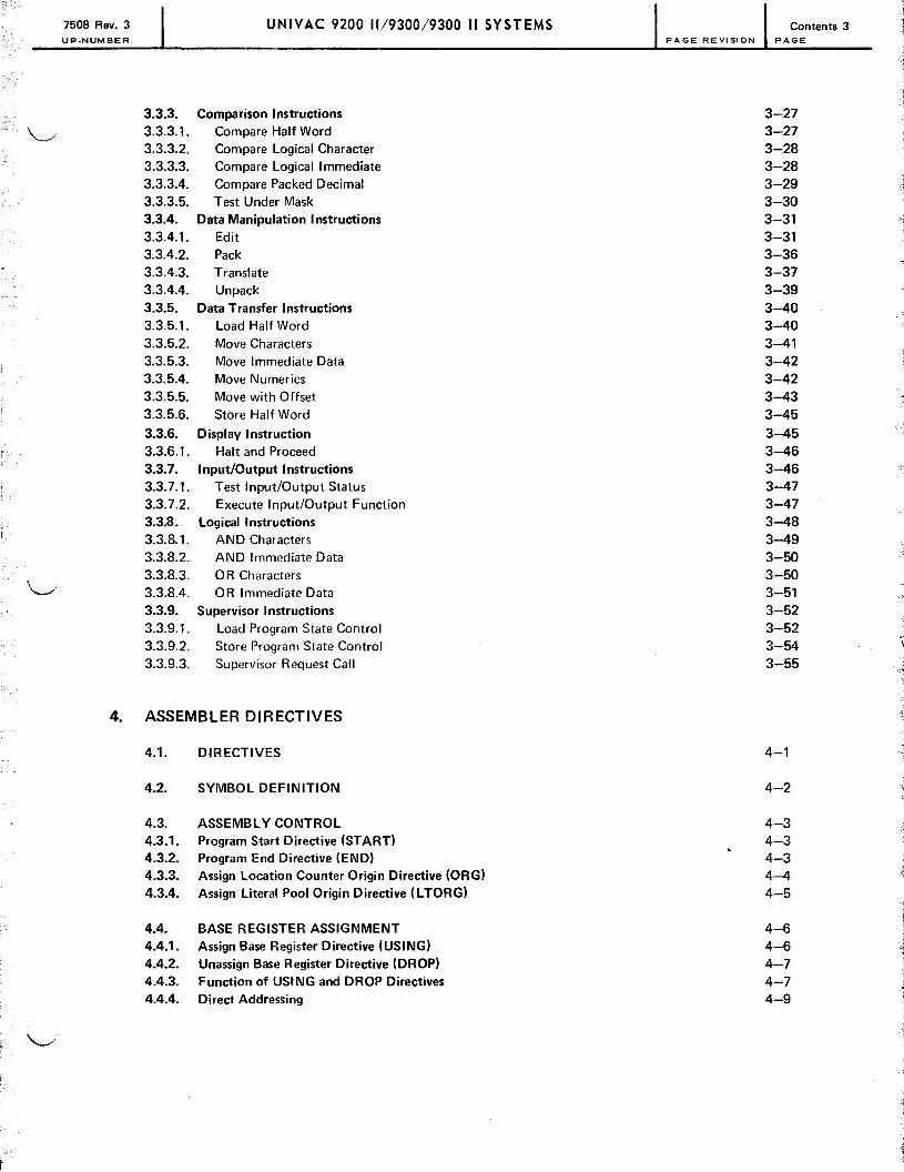
3.3.3. Comparison Instructions 3-27 ~. 3.3.3.1. Compare Half Word 3-27
3.3.3.2. Compare Logical Character 3-28 3.3.3.3. Compare Logical Immediate 3-28 3.3.3.4. Compare Packed Decimal 3-29 3.3.3.5. Test Under Mask 3-30 3.3.4. Data Manipulation Instructions 3-31 3.3.4.1. Edit 3-31 3.3.4.2. Pack 3-36 3.3.4.3. Translate 3-37 3.3.4.4. Unpack 3-39 3.3.5. Data Transfer Instructions 3-40 3.3.5.1. Load Half Word 3-40 3.3.5.2. Move Characters 3-41 3.3.5.3. Move Immediate Data 3-42 3.3.5.4. Move Numerics 3-42 3.3.5.5. Move with Offset 3-43 3.3.5.6. Store Half Word 3-45 3.3.6. Display Instruction 3-45 3.3.6.1. Halt and Proceed 3-46 3.3.7. Input/Output Instructions 3-46 3.3.7.1. Test Input/Output Status 3-47 3.3.7.2. Execute Input/Output Function 3-47 3.3.8. logical Instructions 3-48 3.3.8.1. AND Characters 3-49 3.3.8.2. AND Immediate Data 3-50 3.3.8.3. OR Characters 3-50 "--i 3.3.8.4. OR Immediate Data 3-51 3.3.9. Supervisor Instructions 3-52 3.3.9.1. Load Program State Control 3-52 3.3.9.2. Store Program State Control 3-54 3.3.9.3. Supervisor Request Call 3-55
4. ASSEMBLER DIRECTIVES
4.1. DIRECTIVES 4-1
4.2. SYMBOL DEFINITION 4-2
4.3. ASSEMBl Y CONTROL 4-3 4.3.1. Program Start Directive (START) 4-3 4.3.2. Program End Directive (END) 4-3 4.3.3. Assign location Counter Origin Directive (ORG) 4-4 4.3.4. Assign Literal Pool Origin Directive (L TORG) 4-5
4.4. BASE REGISTER ASSIGNMENT 4-6 4.4.1. Assign Base Register Directive (USING) 4-6 4.4.2. Unassign Base Register Directive (DROP) 4-7 4.4.3. Function of USING and DROP Directives 4-7 4.4.4. Direct Addressing 4-9
'-.../

7508 Rev. 3 UNIVAC 9200 11/9300/9300 II SYSTEMS Contents 4 UP-NUMBER PAGE REVISION PAGE
4.5. PROGRAM LINKING AND SECTIONING 4-9 4.5.1. Identify Entry-Point Directive (ENTRY) 4-10 4.5.2. Identify Externally Defined Symbols Directive (EXTRN) 4-10 4.5.3. Sectioning 4-10 4.5.4. Control Section Identification (CSECT) 4-11 4.5.5. Dummy Control Section Identification (DSECT) 4-13 4.5.6. Common Storage Definition (COM) 4-14
4.6. LISTING CONTROL 4-17 4.6.1. Listing Content Control (PRINT) 4-17 4.6.2. Listing Format Control (SPACE) 4-18 4.6.3. Listing Format Control (EJECT) 4-18 4.6.4. Listing Format Control (TITLE) 4-18
4.7. INPUT CONTROL 4-19 4.7.1. Input Sequence Control (lSEQ) 4-19
4.8. ERROR CONTROL 4-19 4.8.1. User Program Sense Indicator (UPSI) Byte Setting 4-19 4.8.2. Total Error Count 4-19
5. MACRO INSTRUCTIONS 5.1. MACRO INSTRUCTION FORMAT 5-1 5.1.1. Parameters 5-1
5.2. WRITING MACRO INSTRUCTION DEFINITIONS 5-3 0
5.3. INCORPORATING PARAMETERS INTO MACRO DEFINITION CODING 5-4
5.4. NAME DIRECTIVE 5-5
5.5. BUILT-IN MACROS DEFINITIONS 5-7
6. CONDITIONAL ASSEMBLY INSTRUCTIONS
6.1. GENERAL 6-1
6.2. DO AND ENDO DIRECTIVES 6-1 -- -- -
6.3. GOTO AND LABEL DIRECTIVES 6-2
6.4. CHARACTER EXPRESSIONS 6-4
6.5. SET VARIABLES 6-4 6.5.1. GBL Directive 6-5 6.5.2. LCL Directive 6-5 6.5.3. SET Directive 6-5 6.5.4. Relational and Logical Operators 6-6 6.5.5. Use of Character Expressions 6-6
6.6. CONCATENATION 6-9 -J
7508 Rev. 3 UNIVAC 9200 11/930019300 II SYSTEMS Contents 5 UP.NUMBER PAGE REVISION PAGE
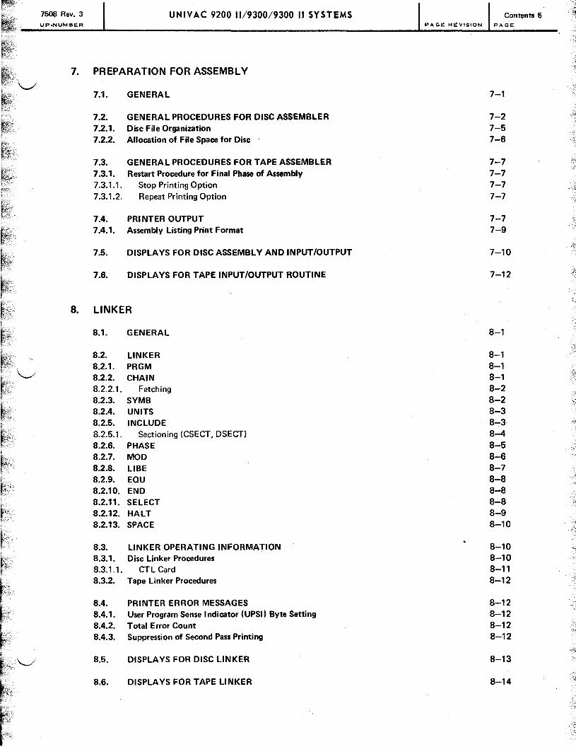
7. PREPARATION FOR ASSEMBLY
7.1. GENERAL 7-1
7.2. GENERAL PROCEDURES FOR DISC ASSEMBLER 7-2 7.2.1. Disc File Organization 7-5 7.2.2. Allocation of File Space for Disc 7-6
7.3. GENERAL PROCEDURES FOR TAPE ASSEMBLER 7-7 7.3.1. Restart Procedure for Final Phase of Assembly 7-7 7.3.1.1. Stop Printing Option 7-7 7.3.1.2. Repeat Printing Option 7-7
7.4. PRI NTER OUTPUT 7-7 7.4.1. Assembly Listing Print Format 7-9
7.5. DISPLAYS FOR DISC ASSEMBLY AND INPUT/OUTPUt 7-10
7.6. DISPLAYS FOR TAPE INPUT/OUTPUT ROUTINE 7-12
B. LINKER
8.1. GENERAL 8-1
8.2. LINKER 8-1 8.2.1. PRGM 8-1 8.2.2. CHAIN 8-1 8.2.2.1. Fetching 8-2 8.2.3. SYMB 8-2 8.2.4. UNITS 8-3 8.2.5. INCLUDE 8-3 8.2.5.1. Sectioning (CSECT, DSECT) 8-4 8.2.6. PHASE 8-5 8.2.7. MOD 8-6 8.2.8. LlBE 8-7 8.2.9. EaU 8-8 8.2.10. END 8~8
8.2.11. SELECT 8-8 8.2.12. HALT 8-9 8.2.13. SPACE 8-10
8.3. LINKER OPERATING INFORMATION 8-10 8.3.1. Disc Linker Procedures 8-10 8.3.1.1. CTL Card 8-11 8.3.2. Tape Linker Procedures 8-12
8.4. PRINTER ERROR MESSAGES 8-12 8.4.1. User Program Sense Indicator (UPS!) Byte Setting 8-12 8.4.2. Total Error Count 8-12 8.4.3. Suppression of Second Pass Printing 8-12
8.5. DISPLA YS FOR DISC LINKER 8-13
8.6. DISPLAYS FOR TAPE LINKER 8-14

7508 Rev. 3 UNIVAC 9200 11/9300/9300 II SYSTEMS Contents 6 UP.NUMBER
APPENDIXES
A. TAPE LANGUAGE PROCESSOR CONVENTIONS
B. STANDARD CARD, EBCDIC, AND PRINTER GRAPHIC CODES
USER COMMENT SHEET
FIGURES
2-1. Assembler Coding Form 2-2. Example of Source Code Statements
3-1. Assembly Listing
4-1. Relocation of the Common Section
7-1. Disc Drive Assignment Examples
TABLES
1-1. Data Formats
2-1. Constant Characteristics
3-1. Instruction Mnemonics 3-2. Instruction Types 3-3. Instruction Formats 3-4. Instruction Execution Times 3-5. Instruction Symbols 3-6. Hardware Multiply Timing 3-7. Instruction Object Code Formats 3-8. Complete and I mplied Specifications for Operands 3-9. Extended Mnemonic Codes
7-1. Printer Error Codes 7-2. Disc Assembler Displays 7-3. Disc Assembler Input/Output Displays 7-4. Tape Assembler Input/Output Displays
8-1. Linker Printed Error Messages 8-2. Disc Linker Displays 8-3. Tape Linker Displays
8-1. Standard Codes
PAGE REVISION PAGE
2-2 2-3
3-10
4-15
7-5
1-2
2-11
3-2 3-3 3-4 3-5 3-7 3-7 3-10 3-12 3-26
7-8 7-10 7-11 7-12
8-13 8-14 8-14
8-1

7508 Rev. 3 UP·NUMBER
UNIVAC 920019200 11/930019300 II SYSTEMS 1-1 PAGE REVISION PAGE
1. Introduction
1.1. GENERAL
The purposes of this manual are to afford the information necessary for programming the SPERRY UNIVAC 9200/9300 Series Tape/Disc Assembler and a reference handbook for the programmer. The use of the assembler coding form and the operational characteristics of the assembler are described in succeeding sections. These characteristics are summarized briefly as follows:
• Mnemonic Operation Code
A fixed name, suggestive of the nature of the instruction and consisting of 2, 3, or 4 letters, is assigned to each instruction. This applies to each variant of the branch instructions as a further aid in writing the program.
• Symbolic Addressing and Automatic Storage Assignment
Symbolic labels can be assigned to instructions or groups of data. An instruction then references the labeled data by the label rather than the storage address. In many cases, other data required by the instruction (such as operand length) can be supplied automatically by the assembler. The assembler also keeps track of all storage locations used for a particular program and assigns all incoming instructions and data to specific locations. The assembler performs base register and displacement calculations.
• Flexible Data Representation
Data may be represented in the assembler in binary, hexadecimal, decimal, or character notation, allowing the programmer to choose the most suitable form for each constant.
• Relocatable Programs and Program Linking
•
Programs are prepared by the assembler in absolute or relocatable form. In absolute form, the program storage locations are specified within the program. In relocatable form, the actual storage locations to be ()Ccupied by a program need not be specified, but if specified, they may be altered easily before loading. Provisions are made for linking together, loading, and running as one program the results of separate assemblies. The machine time needed to make changes to one part of a program is reduced by use of this provision. The input of one assembly can be divided into separate sections, each of which consists of a group of instructions or data, or both, occupying contiguous locations. The relative positions of the various sections can be declared at the time the program is linked. The output of the assembler is not in loadable form; it must be linked before loading.
Macro Instruction Facility
The assembler includes a macro instruction facility that reduces the effort required to write patterns of coding repeated in one program or common to several programs. One command to the assembler results in the inclusion in the object program of many instructions and/or constants, or merely results in establishing one or more values for use elsewhere within the program. The flexibility of the facility allows a macro to be written so that the generated pattern of coding can vary widely depending upon the parameters supplied with the call.

7508 Rev. 3 UP-NUMBER
UNIVAC 9200/9200 11/9300/9300 II SYSTEMS 1-2 PAGE REVISION PAGE
• Program Listing
A printed listing of source and object codes is one output of the assembler. This listing includes error message flags marking any errors detected by the assembler. Source-code errors do not cause the assembly process to halt; the assembler continues to process the remainder of the source code, performing its usual error checks, minimizing the number of assemblies required to produce error-free code.
A computer with a tape or disc subsystem can handle data faster than a comparable card-oriented system. The SPERRY UNIVAC 9200/9300 Series Tape/Disc Assembler relies heavily on the larger storage and file-handling capabilities of the tape or disc subsystem to perform many processing operations normally difficult to perform with cards only. A built-in macro instruction facility is one of the features of the assembler. Another feature is the linker program that provides. a method of combining several separately assembled modules into one executable program.
1.2. DATA FORMATS
The basic unit of data in the SPERRY UNIVAC 9000 Series is an 8-bit byte to which a parity bit is added when the byte is stored in main storage. A byte may represent a character or a number. Main storage locations are numbered consecutively. Each address specifies on byte of information. The address of a group of bytes is the address of the leftmost byte of the group. The bits in a byte also are numbered from left to right, starting with zero. Each of the formats is illustrated in Table 1-1.
Table 1-1. Data Formats
Byte
0----7
Half·word data formats consist of two consecutive bytes.
Half Word Iblblblblblblblblblblblblblblblbl o 7 8 -15
Full·word data formats consist of four consecutive bytes.
Full Word IblblblblblblblblblblblblblblblblblblblblblblblblblblbIblblblblbl o 7 8 1 C; 1 fi 23 24 31
Variable data formats consist of a variable number of consecutive bytes.
Variable Data Format
o ---7 First byte
0-----7 Last byte
It is possible to store anyone of 256 different bit combinations in the byte. Data can be represented in various forms to the programmer; however, certain restrictions are imposed if the data is to be printed or processed arithmetically. The contents of a byte can be considered a binary number, a decimal number, an alphabetic or symbolic character, or logical information. A field used to represent a binary number uses all of the bit positions (except the sign bit) to contain the value; however, each byte in a field representing a decimal number, alphabetic character, or symbol is considered to be divided into zone and digit portions. The zone portion is the most significant four bits; the digit portion is the least significant four bits.
ZONE DIGIT
b b bib b bib b
0 1
3 4 I 7

7508 Rev. 3 UP-NUMBER
UNIVAC 9200/9200 11/9300/9300 II SYSTEMS
1.2.1. Binary Number Representation
PAGE REVISION PAGE
The binary arithmetic operand is a 16-bit binary number. The bits of the operand are stored in adjacent locations_ These two consecutive bytes constitute a half word when the address of the more significant byte is an integral multiple of two. Such an address is a half-word boundary.
Positive binary numbers are represented in conventional binary notation with a 0 bit in the most significant bit position; this is the sign bit for a binary number.
sign 2 bytes
l ____ -------------~--~-------------
Negative numbers are represented as the twos complement of the number with a 1 bit in the sign position. For instance, the representation of the negative number -19,761 would be determined as follows:
The binary equivalent of 19,761 is: o 1 001 101 001 1 000 1
The ones complement is: o 1 o 0 0 1 001 o
The twos complement formed by adding 1 is: o 1 o 0 0 1 001
With the sign bit set to 1 for a negative number, the two bytes appear as:
1 0 1 1 0 0 1 0 1 1 0 0 1 1 1 1
0 1 7 8 15
The largest possible values that may be represented in the binary format are +32,767 and -32,768.
1.2.2. Hexadecimal Representation
Hexadecimal digits are base 16 numbers with values 0 through F(15). A hexadecimal digit is used to denote a particular bit pattern in the zone or digit portion of a byte representing a decimal number, or alphabetic or symbolic character. (Hexadecimal digits also are used for constant definition as described in Section 2.) The hexadecimal digits and their binary values are:
Hexadecimal Binary Hexadecimal Binary Digit Value Digit Value
0 0000 8 1000 1 0001 9 1001 2 0010 A 1010 3 0011 B 1011 4 0100 C 1100 5 0101 D 1101 6 0110 E 1110 7 0111 F 1111
1-3

7608 Rev. 3 ·.,lJp.Nu .... aER
UNIVAC 9200/9200 11/9300/9300 II SYST EMS
1.2.3. Decimal Number Representation
PAGE REVISION
Decimal numbers are represented in unpacked form (one digit per byte) or packed form (two digits per byte).
PAGE
In unpacked form, the byte is divided into zone and digit portions. The zone portion usually contains a hexadecimal F bit configuration (1111), which is ignored except in the least significant byte; the zone portion of the least significant byte is interpreted as the sign of the number.
ZONE DIGIT ZONE DIGIT ZONE DIGIT SIGN DIGIT
In packed form, digits are contained in both halves of a byte except the least significant half byte of the field, which is interpreted as the sign of the number.
DIGIT DIGIT DIGIT DIGIT DIGIT DIGIT DIGIT SIGN
The interpretation of the contents of the sign position is:
Hexadecimal Binary Sign Character Value Value
0-8 0000-1000 Positive 9 1001 Negative A 1010 Positive* B 1011 Negative* C 1100 Positive (EBCDIC mode)** D 1101 Negative (EBCDIC mode)** E 1110 Positive (EBCDIC mode) F 1111 Positive (EBCDIC mode)***
* Generated when processor is in the ASCII mode. ** Automatically generated in the central processor for decimal operations.
*** Automatically generated in the central processor for a zone fill during unpack instruction.
1.2.4. Character Representation
An alphabetic or other symbolic character representation is contained in the full eight bits of a byte. A character field is considered as not containing a sign. This type of field is represented: ~
ZONE : DIGIT I
ZONE i DIGIT I
DIGIT ZONE ZONE DIGIT ----- ----------- -----~ CHARACTER CHARACTER CHARACTER CHARACTER
CHARACTER REPRESENTATION
C'D' -C'GROSS' e'9'
BINARY VALUE (EBCDIC CODE)
11000100 1100011111011001110101101110001011100010
11111001
1-4

7508 Rev. 3 UNIVAC 9200/9200 11/9300/9300 II SYSTEMS 1-5 UP-NUMBER PAGE REVISION PAGE
1.2.5. Logical Information
Logical information consists of alphabetic or numeric character codes. This information is used in operations such as compare, translate, edit, bit setting, and bit testing. Logical information is processed as fixed- or variable-length data and from left to right, one byte at a time. Variable-length logical information consists of up to 256 bytes.
1.3. STATEMENT CONVENTIONS
The conventions used to illustrate statements in the manual are:
• Capital letters and punctuation marks (except braces, brackets, and ellipses) are information that must be coded exactly as shown.
• Lowercase letters and terms represent information that must be supplied by the programmer.
• Information contained within braces represents necessary entries, one of which must be chosen.
• Information contained within brackets represents optional entries that (depending on program requirements) are included or omitted. Braces within brackets signify that one of the entries must be chosen if that operand is included.
• An ellipsis indicates the presence of a variable number of entries.
• Commas are required after each parameter except after the last parameter specified. When a positional parameter is omitted from a series of parameters, the comma must be retained to indicate the omission.

f;--
~ -

7508 Rev. 3 UNIVAC 9200/9200 11/9300/9300 II SYSTEMS UP·NUMBER PAGE REVISION PAGE
2. Assembler Language
2.1. CHARACTE R SET
The character set used in writing statements in the SPERRY UNIVAC 9200/9300 Series Tape/Disc Assembler language consists of:
Letters A, B, C, ... ,Z
Digits 0,1,2, ... ,9
Special symbols / = & . * + - , ( ) , blank
The correspondence between graphics and internal code assumed by the assembler is shown in Appendix B.
2.2. STATEMENT FORMAT
Statements in the assembler language are written on a standard coding form, shown in Figure 2-1. Information for the assembler and comments are written in columns 1 through 71. Columns 73 through 80 may contain program identification and sequencing information. The information in columns 1 through 72 consists of the following fields.
2.2.1. Label Field
The label field begins in column 1 and is terminated by a blank column. There may be no embedded blanks. It may be a blank field or contain a symbol of undefined value. More detailed information about symbols is contained in 2.3.4.
2.2.2. Operation Field
The operation field begins with the first nonblank following the label field and is terminated by a blank. It contains the name of an assembler directive, the mnemonic operation code for a machine instruction, or the name of a macro instruction.
2.2.3. Operand Field
The operand field begins with the first nonblank following the operation field and is terminated by a blank not contained in a character representation. This field contains information that defines the operands of a machine instruction or supplies the specifications required with an assembler directive.
2-1
. -~
.~ - - ~

Si-lSr::<RY+UNIVAC ASSEMBLER CODING FORM UNIVAC @'.'.'-I BEAlES
PROGRAM _________________________________________________ __ PROGRAMMER DATE PAGE ___ DF ___ PAGES
lABEL tDi'ERATIONt:. OPERAND b. COMMENTS t tD t6 72 8D
I I I I I I ! ! I I I ! I I
I I I I I I I I .L- I I I I I I
I I I ! I ! I I I I I I I I
I I I I I I I I j I I I I !
I I I I I I I I I I I I I I
I I I I I I I I I I I I I I
I I I I I I I I I I I I I I I I I I I I I I I I I I I I . I I I I I I I I I I I I I I . I I I I I I I I I I I I I I
I I I I I I I I I I I I I I
I I I I I I I I I I I I I I
I I I I I I I I I I I I I I
I I I I I I I I I I I I I I
I I I I I I I I I I I I I I
I I I I I I I I I I I I I I
I I I I I I I 1 1 I I I I I
I I I I I I I I I I I I I I
I I I I I I I I I I I I I I
I I I I I I I I I I I I I I
I I I I I I I I I I I I I I
I I I I I I I I I I I I I I
I I I I I I I I I I I I I I I I I I I I I I I I I I I
I I I I I I I I I I I I I I
I I I I I I I I I I I I I I
I I I I I I I I I I I I I I
I I I I I I I I I I I I I I r
I I I I I I I I I I I I I I t I I I I I I I I I . .J.-.-J __ l-----L-l I I I I I I I I __
I I I I I I I I I I I J J _LL..L.L.l I I I I I I 1...1._
I I I I I I I I I I I I I I I
Figure 2-1. Assembler Coding Form
( ( (
c .....
i ~ C JJ ~ .. UI ~ ~ Co)
1]
» Gl tTl
:II tTl < III
0 Z
1]
» Gl tTl
c: z < ~ n -0 t.J o o "-0 t.J o o
"-0 W o o "-0 W o o
'" -< '" -I m ~
'"
p.,)
I p.,)

7508 Rev. 3 UNIVAC 9200/9200 11/9300/9300 II SYSTEMS
UP.NUMBER PAGE REVISION PAGE
2.2.4. Comments Field and Comments Line
The comments field begins with the column following the blank terminating the operand field and ends at column 71. It may contain any combination of characters including blanks. It is not processed by the assembler other than including it on the assembly listing. It may contain remarks to clarify the purpose or operation of the associated coding. A line may consist entirely of comments from columns 2 through 80 if column 1 contains an asterisk. If it is desired to write comments on a line containing a blank operand field, a comma, followed by a space should be placed in the operand field to denote its termination. If this is not done, the first portion of the comments field will be treated as part of the operand field.
Although the assembler language is free form, it is recommended that source code statements be written with the first character of the operation code in column 10 and the first character of the operand field in column 16. Tabulating the statements in this fashion creates a program listing neater in appearance and easier to read. The standard coding form is ruled to conform to this convention. Thus, although the statements on lines 3 and 4 of Figure 2-2 are equivalent to the assembler, the form of line 4 is preferred to that of line 3.
2
3
..
LABEL 1
* THII
TAG I
LH 1 15
I
s
f:j, OPERATION f:j, 10
I sl A CO
BIA L
TA GI3
LIH
OPERAND 16
M MEN TI L , N EI I I I
1 5, TAIG2 J I I I I I I
THE 101 PIEIR IA ITII a N I COlD E II
1 5 T AIG 3 I I I i I I
Figure 2-2. Example of Source Code Statements
2.2.5. Continuation Line
f:j,
I I
I I I I I I I I I I I
S I ILl H I I I _11 1 1
I I I 1 I
If necessary, a statement may occupy more than one line of the coding form. In this case, a nonblank character is placed in column 72 of the first line of the statement, and the statement is continued, beginning with column 16 of the succeeding line of the form. Columns 1 through 15 of the second line must be blank. The statement can be continued on a third line by placing a nonblank character in column 72 of the second line and continuing the statement in column 16 of the following line. Column 72 must be blank in the last (or only) line of each statement.
If the operand field of a line is terminated, prior to column 71, by a comma followed by a space, and a nonblank character appears in column 72 of the line, the operand field is continued in column 16 of the succeeding line. Comments are written after the space terminating the portion of the operand field on the first line.
2.3. EXPRESSIONS, TERMS, AND OPERATORS
The operand field of a statement in the assembler language ordinarily consists of one or more expressions. Expressions are separated by a comma or parenthesis. Examples of the basic operand formats for instructions are shown in Table 3-8. In this table, each letter represents an expression. An expression may be a single term or a number of terms connected by operators. The permissible operators are a plus sign (+) representing addition, a minus sign (-) representing subtraction, an asterisk (*) representing multiplication, and a slash (I) representing division. A leading minus sign also is allowed to produce the negative of the first term. A term may be:
2-3
-~

7508 Rev. 3 UNIVAC 9200/9200 11/9300/9300 II SYSTEMS P.NUMBER PAGE REVISION PAGE
• a decimal, hexadecimal, or character representation of an actual value;
• a location counter reference;
• a symbol;
• & reference to the length attribute of a symbol or of an EXTRN label (with a length attribute of 1); or
• a literal.
2.3.1. Representations of Actual Value
A value may be:
• a value represented directly by a string of up to five digits, forming a binary number from 0 through 65,535, which is converted to a binary value occupying one or two bytes depending on the type of field for which it is intended;
• a value represented by a string of hexadecimal digits identified by a preceding X' and a following , (apostrophe), each digit occupying half a byte; or
• a value represented by a string of characters identified by a preceding C' and a following' (apostrophe).
For additional information concerning value representations, see 1.2.
2.3.2. Location Counter
An indication of the next storage location available for assignment is maintained as a counter, called the location counter. After the assembler processes an instruction or constant, it adds the length of the processed instruction or constant to the location counter.
The address of each instruction or address constant must be a multiple of two. Such an address is said to fall on a half·word boundary. If the value of the location counter is not a multiple of two when assembling such a constant or an instruction, a 1 is added to the location counter before assigning an address to the current line. Storage locations reserved by this process receive binary O's when the program is loaded.
The current value of the location counter is available for reference in the assembler language and is represented by the single special character * (asterisk). If written in a constant representation or in an instruction operand expression, this symbol is replaced by the storage address of the leftmost byte allocated to that instruction or constant. Thus the following instruction represents a one-instruction loop.
LABEL 11 OPERATION 11 OPERAND 10 16
2-4
/j.

7508 Rev. 3 UP.NUMBER
UNIVAC 9200/9200 11/9300/9300 II SYSTEMS 2-5 PAGE REVISION PAGE
2.3.3. Relative Addressing
An instruction may address data in its immediate vicinity in the storage in terms of its own storage address. This is a form of addressing achieved by an expression of the form * +n or * -n where n is the difference in storage addresses of the referring instruction and the instruction or constant being accessed. Relative addressing always is in terms of bytes, not words or instructions. For example, in the coding
1
2
3
4
5
1 LABEL
I
~i 1
1
I
~J I
!1 OPERA liON !1 10
CIH
BIC
AIH
BIC
MIVIC
16
1 5
7 'I
1 5
1 5
A,
OPERAND
L I IN E T I I
* 1+1 1 1 21 I 1 1 1 1
, T WIO 1 1 1 t 1
* • 11 2 I
BI I I
!1
I 1 1 1 1 1 1 1 t 1 1 1 1 t 1 1 1 1 1
1 1 1 1 1 I 1 1 I 1 1 1 1 1 1 1 1 1 I
1 1 1 I I 1 1 1 I 1 I 1 1 I I 1 1 1 I I I I I Illl
I I I I
the address *+12 in line 2 is the address of the instruction in line 5 and the address * -12 in line 4 is the address of the instruction in line 1 because each of the first four instructions is four bytes long.
Storage addressing is described in 2.5.
2.3.4. Symbols
A symbol is a group of as many as eight alphanumeric characters. The first, or leftmost, must be alphabetic. Special characters or blanks may not be contained within a symbol. The following are examples of valid symbols:
A LOSS
A72Z PROFIT
CAT GRSVALUE
The following are not valid symbols for the reasons stated:
GROSSVALUE more than eight characters
N PA embedded blank
SR)N special character
A symbol may be assigned any value from 0 through 65,535. It is assigned a value, or defined, when it appears in the label field of any source·code statement other than a comment. A symbol appearing in the label field of an EQU or ORG directive is assigned the value of the expression in the operand field. In all other cases, the value assigned is the current value of the location counter after any necessary adjustment to a half-word boundary. The value is assigned to the current label before the location counter is incremented for the next instruction, constant, or storage definition. Thus, if a symbol appears in the label field of a statement defining an instruction, constant, or storage area, the symbol is assigned a value equal to the storage area address of the first byte of that instruction, constant, or storage area.

7508 Rev. 3 UP-NUMBER
UNIVAC 9200/9200 11/9300/9300 II SYSTEMS
2.3.5. Relocatable and Absolute Expressions
PAGE REVISION PAGE
A single term may be absolute or relocatable. Decimal, character, and hexadecimal representations are absolute terms. In general, a term is absolute unless the expression consists of:
• a location counter reference within a section of relocatable coding;
• a symbol defined by its appearance in the label field of a section of relocatable coding;
• an absolute expression plus a relocatable term; or
• an expression that can be rendered or reduced to an absolute expression plus a r~locatable term.
In addition to these relocatable expressions, a negatively relocatable expression is possible. Such an expression consists of an absolute expression minus a relocatable expression, or an expression that may be reordered to that form.
2.3.6. Length Attribute
A length attribute is associated with the operation of most instructions in the repertoire of machine instructions_ This length determines the number of bytes to be compared, moved, translated, displayed, or manipulated logically or arithmetically. In the cases of RX and SI format instructions (3.2.1), the operation is performed on fixed-length data and no length specification is needed. For SS1 and SS2 formats, some length specification must be made in the operands to control the amount of data affected by the instruction. If a length is not specified in the operands of SS1 and SS2 format instructions, the assembler supplies a length in accordance with the following principles.
A symbol defined in the label field of a source-code line representing an instruction, constant, or storage allocation is assigned the length associated with the instruction, constant, or storage area involved.
LABEL 6. OPERA TION 6. OPERAND 6. 1 10 16
AVR I MIV C TAG, Via R I I I I I
VOR LLi DLCi j; • ,F ,0 Uj RI • 1 1 I I I I
TAG 1 1 i i DLSi J , C L 1 4 I I 11 I 11 i 1 I I I I 1 I I 1 I I I
In the preceding example, AVR is six bytes long because an MVC is a 6-byte instruction, VOR is four bytes because the constant occupies four bytes, and TAG is 14 bytes because the storage area is defined as such. The instruction labeled AVR moves 14 bytes of data because the implied length of TAG is 14.
The length attribute of an expression is a function of the leading term. If the first term is an absolute value, a length attribute of one byte is assigned. If the first term is a symbol, the length of the symbol is assigned to the expression.
II::: :~: : II~~ :::: :~::: : : ::: ::: : : : : : : : : : : : : : : : : : : : : :
2-6

7508 Rev. 3 UP-NUMBER
UNIVAC 920019200 11/930019300 II SYSTEMS PAGE REVISION PAGE
In the preceding example, the expression 16+TAG is assigned a length of one byte because the leading term is an absolute value, and the expression RTF+16 is assigned a length of six bytes, which is the length of the term RTF.
When a location counter reference appears as the first term of an expression, the expression is assigned a length attribute equal to the length of the instruction or, if the reference to the location counter appears in an EQU statement, the length attribute is one byte.
LABEL 6. OPERA nON 6. OPERAND 6. 1 10 16
I MIV C * + 1 2 lAB C I I I J I
DFG I EIQ U * I I I I I I I I I I I I I I I I I I I
In the preceding example, the expression *+12 is assigned a length of six bytes because MVC is a 6-byte instruction, and DFG is assigned a length of one byte because the location counter reference appears in a EQU statement.
The length attribute of an expression may be referenced in assembler coding by the label with the symbol L' preceding it:
L'DFG
is a reference to the length of the expression DFG.
In the foregoing example, the move character instruction affects 10 bytes because the length attribute reference was to SOME, which was defined as 10 bytes long. The unpack instruction affects six bytes because the length attribute reference was to INTR, which appeared in the label field of an MVC instruction, a 6-byte instruction.
If no length is specified in an operand that uses the base register and displacement notation, the length attribute assigned to the operand by the assembler is one byte.
In the first line of the example, the length attributed to each operand is 16 bytes, as specified. In the second line, the assembler assigns a length of one byte to each operand.
2-7

7508 Rev. 3 UP-NUMSER
UNIVAC 9200/9200 11/9300/9300 II SYSTEMS 2-8 PAGE REVISION PAGE
2.3.7. Evaluation of Expressions and Hierarchy of Operators
The standard mathematical rules of precedence are applied in evaluating expressions; that is, multiplications and divisions are performed before additions and subtractions. Operations of the same precedence are performed from left to right. Parentheses may be used to group terms, overriding the natural precedence of the operators.
The following rules must be observed in writing expressions:
• Two operators may not appear in succession. Write
A*(-B) but not
A*-B
• A relocatable expression, an expression involving an external reference (4.5.2), or a negative value, may not enter a division. Such a term may be a factor in a multiplication only if the other factor has a value of 0 or 1.
2.4. DATA STORAGE AND CONSTANT FORMATS
The formats for data storage and constant definitions consist of a label field and operation field plus four subfields in the operand field: duplication factor, type length factor, and constant.
Any symbol, as previously defined (2.3.4), may be used in the label field; this use of a symbol is optional.
The operation code is DC for defining constants and OS for defining storage. In either case, the area is assigned the address of the leftmost byte, and the length associated with the data is available to the assembler each time the area is referenced.
2.4.1. Define Constant Statements
The DC statement specifies data that is to be used as stored constants. These constants are produced in object code along with the program instructions. The format of the DC statement is:
LABEL D. OPERA TION D. OPERAND
[ symbol1 DC [d1 t [Lnl 'c'
where:
d Is the optional duplication factor subfield.
t
Is the type subfield.
Ln Is the optional length factor subfield.
'c' Is the constant subfield.
'-..:.-.,':'

7508 Rev. 3 UNIVAC 9200/9200 11/9300/9300 II SYSTEMS 2-9 UP.NUMBER PAGE REVISION PAGE
2.4.2. Define Storage Statements
The OS statement specifies a storage area to be reserved by the assembler. The format of the OS statement is:
LABEL 11 OPERATION 11 OPERAND
[ symbol 1 DS [d] t [Ln] ['c']
where:
d Is the optional duplication factor subfield.
t
Is the type subfield.
Ln Is the optional length factor subfield.
'e'
Is the optional constant subfield.
The subfields are explained in 2.4.4; however, the following modifications for a OS statement should be noted:
• A constant may be specified in the appropriate subfield of a OS statement, but the constant is not assembled. In H, Y, and S types, the constant is ignored, and in the other types it serves only as a determination of the size of the area defined.
• Storage areas defined by OS statements are not cleared of their contents upon loading.
• Grouping of all OS statements in a program is a good programming practice.
2.4.3. Literals
A constant may be defined explicitly by writing a define constant (DC) assembler directive, or more directly by writing a literal. A literal is written by entering an equal sign (=) in the appropriate portion of the operand field, followed immediately by the description of the constant exactly as it would have appeared in the operand field of a DC directive. The appearance of a literal in a source statement causes the assembler to:
• include the constant in the program the assembler is producing;
• assign an address to the constant; and
• insert the address of the constant in the appropriate portion of the instruction being assembled.
Constants derived from literals are collected into a pool by the assembler. In the absence of other directions to the assembler (4.3.4), this pool is assigned addresses starting at the end of the first control section. Duplicate constants are eliminated from the literal pool on the basis of value, not of form. This is not true for type Y or H constants. Type Y or H constants, which appear to duplicate others, are eliminated only if the forms are identical.

7508 Rev. 3 UNIVAC 9200/9200 11/9300/9300 II SYSTEMS 2-10 UP.NUMBER PAGE REVISION PAGE
An example of the use of a literal is:
LABEL fj, OPERA 1101'1 fj, OPERAND 10 16
The following rules must be observed in the use of literals:
• A literal may appear only as the single term defining a storage address operand of an instruction.
• A literal may not appear in an address field defining the receiving address of an instruction that modifies storage.
• A source-code line can incorporate no more than one literal.
• Reference to the location counter may not be made in a literal.
• Literals may not be used for type S constants.
• A duplication factor of zero is not permitted.
2.4.4. Operand Subfields
The operand field of the DC and DS statements is divided into duplication factor, type, length factor, and constant -.......,...i subfields, which describe or identify the data or storage area to be generated.
The subfields must be specified in the stated order with the duplication factor first and the constant last. Some subfields may be omitted; however, the type subfield always must be present.
The following is a valid example of a typical DC statement with the subfields identified:
TEO 1 L DIC I 3 C L I 3 • ]K1L1P • I I I I I I I I . -r-
I I 1 1 i 11 I I I I I I I I I I I I I I I I I I I I I
duplication factor -type ~
length factor
constant

7508 Rev. 3 UNIVAC 9200/9200 11/9300/9300 II SYSTEMS 2-11 UP.NUMBER PAGE REVISION PAGE
2.4.4.1. Duplication Factor Subfield
The duplication factor indicates to the assembler the number of identical constants to be generated. If no duplication factor is specified, the assembler assumes a factor of one. A duplication factor of zero does not generate a constant or storage area, but advances the location counter for proper boundary adjustment if no length is specified and assigns the location counter value to the symbol in the label field.
2.4.4.2. Type Subfield
The type subfield indicates to the assembler the type of constant or storage area to be generated. The types of constants and their characteristics are listed in Table 2-1. For further descriptions of the types, see 2.4.6.
Table 2-1. Constan t Characteristics
Constant EXplicit Implicit Truncation Value Alignment Constant Type Length Length or Padding Padded Form
C Variable Maximum On right Blanks None Character 1- 256 256 side (EBCDIC)
X Variable Maximum On left Hexadecimal None Hexadecimal 1 - 256 256 side 0 digits
P Variable Maximum On left Hexadecimal None Packed 1 - 16 16 side 0 decimal
Z Variable Maximum On left EBCDIC None Unpacked 1 - 16 16 side 0 decimal
H Variable 2 On left Hexadecimal Half word* Binary 1-2 side 0
y Variable 2 On left Hexadecimal Half word* Binary 1-2 side 0 address
S 2 2 None None Half word* Base and displacement
* Half·word alignment takes place only if implicit lengths are used.
2.4.4.3. Length Factor Subfield
The length factor subfield designates the number of bytes to be used in generating the data or storage area. The length factor must follow the character 'L' and may be any unsigned decimal within the length limitations of the statement type. The maximum length of any DC statement is 256 bytes, but each type is limited (Table 2-1). The maximum does not apply to DS statements of the C or X type, where the size of main storage associated with the processor is the critical factor.
If no length factor is specified, the size of the generated area is a function of the constant subfield in C, X, P, and Z type statements, and is two bytes for H, Y, and S types (Table 2-1). If the supplied length is less than or more than that needed to express the constant specified in its subfield, truncation or padding occurs as specified in Table 2-1.
--~
:-~
--"-j
.. ~

7508 Rev. 3 UNIVAC 9200/9200 11/9300/9300 II SYSTEMS 2-12 UP-NUMBER PAGE REVISION PAGE
Boundary adjustments are performed only on constants with no supplied length factor.
lABEL 6. OPERATION 6. OPERAND 6. 1 10 16
E X 1 I _1 DIC S ( 3 2 0 I ( 1 2 ) ) I I I 1 I I 1 I 1 I 1
E X 2 J DIC Cl 2' AI' I I I I I
~31 I I 1 DIC 1 1 X1L L21' IFIC I 114 10J'I11 I I 1 1 1 I 1 1 I I J1 i _I 1 I I
E1X14 I I DIC Cll 2' AI B CI'j 1 1 I 11 1 I IL I _I I I
Each of the foregoing lines of coding produces the following in binary notation:
1100 0001 0100 0000
Each line produces the same constant because of the modification performed by the length specification on the constant originally specified in the coding. In EX 1, the address constant is assigned a length of two bytes and translated into binary notation; the base register number occupies the first four bits. In EX2, a character representation two bytes long is specified. To fill the required length, a blank is padded on the right of the constant. The hexadecimal constant, EX3, is too long to fit into the specified length of two bytes. The first four bits are truncated. EX4 specifies a character constant too long for the length specified; three bytes are truncated on the right.
2.4.4.4. Constant Subfield
The constant subfield specifies the value, subject to modification by the length subfield, of the constant to be generated. The values for the constants are represented in different ways. (See 2.4.6 for the description of the values.) A data value representation is specified by enclosing it in apostrophes, and an address value representation is specified by enclosing it in parentheses.
Data constant Address constant
'constant' (constant)
2.4.5. Alignment
All machine instructions must be aligned on half-word boundaries such that the address of the first byte of the instruction must be divisible by 2. Constants, however, can be aligned on a half-word, or no boundary at all. The kind of alignment, when necessary, for data or storage definition statements if no length factor is stated is shown in Table 2-1. When a length factor is specified by the programmer, no alignment is provided. A duplication factor of zero in DC and DS statements does not generate a constant or storage area, but, for some types of constants, it forces a boundary alignment if no length factor is coded. This method affords a convenient means of obtaining a boundary alignment before generating a constant not automatically aligned by the assembler. Any bytes skipped to align constants are zero filled; however, bytes skipped to align storage areas are not zero filled.

· 7508 Rev. 3 UNIVAC 9200/9200 11/9300/9300 II SYSTEMS UP.NUMBER PAGE REVISION PAGE
2.4.6. Data Constant Types
Data constants are absolute values generated by the assembler and require no modification upon loading. Of the five types of data constants, four do not require boundary alignment; that is, the first byte of these constants can be assembled at any storage address. These constants are discussed in 2.4.6.1 through 2.4.6.4; the one data·constant type requiring boundary adjustment is discussed in 2.4.6.5.
Each type of constant is described and examples of its use are shown in typical DC statements.
2.4.6.1. Character Constants
A character constant is specified by the character C in the type subfield and up to 256 characters enclosed by apostrophes in the constant subfield. Any of the 256 valid card punch combinations can be used. Only 63 characters of the 256 valid characters are printable. Each character is stored in one byte using the 8-bit character code. If no length factor is specified, the length in bytes of the constant equals the number of characters specified. If the length factor is present, the character specification is truncated, or filled with blanks, to the right of the last character and to the length specified.
Two consecutive apostrophes or two consecutive ampersands are necessary to generate the character code for one apostrophe or one ampersand within the constant. A single apostrophe in the character representation terminates the constant.
Examples:
2
3
4
5
6
7
8
9
1 LABEL
I
I
I
1 , I
I 1
I
I
I
t:,. OPERA TION t:,. 10
DIC
DIC
IDle
Dlc I
Dlc
DIC j
OIC
DIC
DIC
OPERAND 16
C L 2 ' AI' I
C ' A' I I
C 'A ' I I
C Lll~ 0 ' I E M P Lj jD
C L 1 2 ' I ,
I
C' 5 0 613 • I , C ',H I E, AID, 1,1'1, G, 'I , 3 C L 4 '[1 2 13,4,51' ,
3 CL6 ' 11 2 3 4 51'
t:,.
I I I I
I I I I I I I I I I I I I I I I I
I I I I
I V 1 ' I I I I
I I I , , I
, , I I I , , I I , , , I I , I , I .G , , , I , I , , I , , , , I , , , , I ,
I , , I , , I , I , , , , I , , , , 1 , I I , 1 I
2-13

7508 Rev. 3 UP-NUMBER
UNIVAC 9200/9200 11/9300/9300 II SYSTEMS 2-1"4 PAGE REVISION PAGE
1. Two-byte constant containing:
2. One-byte constant containing:
3. Two-byte constant containing:
4. Ten-byte constant containing:
5. Twelve-byte constant containing blanks:
I I I I I I I 6. Four-byte constant containing:
7. Seven-byte constant containing:
8. Twelve-byte constant containing:
9. Eighteen-byte constant containing:
2.4.6.2. Hexadecimal Constants
A hexadecimal constant is specified by the character X in the type subfield and up to 256 hexadecimal digits enclosed by apostrophes in the constant subfield. Two hexadecimal digits are assembled into one byte. If an odd number of digits is specified, the first, or leftmost, byte of the constant contains a hexadecimal 0 in the four leftmost bits and the first digit in the four rightmost bits. If no length factor is specified, the length, in bytes, of the constant is half the sum of the number of digits or O's specified. If a length factor is present, the decimal specification is truncated, or filled with hexadecimal O's if necessary, on the leftmost end to the length specified.
:~~ "'--' .. ~ -.. ,;::, :~f
"is

7508 Rev. 3 UP-NUMBER
UNIVAC 9200/9200 11/9300/9300 II SYSTEMS 2-15
,~ Examples:
'-../
LABEL /j. OPERA TION /j. OPERAND 1 10 16
I I I ole x L 3 ' Ill' I
I I I ole XI'I112314 1S' I
I ole X' ~BCiI23D'1 I
2
3
4
5
I I I I I I I IOle, I X,LI41' FIFIFI' I
r'.
\....,./
6
7
I
1.
2.
3.
4.
5.
6.
7.
I ole X' F F FlO 0 o ' I
1 ole XL 4 ' AI ' I
1 Ole XL2' 112 3 4 5 ' I
Three-byte constant containing:
100000000 1000000001000000011
Three-byte constant containing:
[000000011001000111010001011
Four-byte constant containing:
100001010 1101111001000100101001111011
Four-byte constant containing:
100000000 1000000001000011111 111111111
Three-byte constant containing:
111111111 1111100001000000001
Four-byte constant containing:
1000000001000000001000000001000010101
Two-byte constant containing:
100100011 1010001011
"'AGE REVISION PAGE
/j.
I I I I
I I I I
I I I I I I I I I I I I I I I I I I I j I I 1
I I 1 I
I I I I
1 I I I

7508 Rev. 3 UP.NUMBER
UNIVAC 9200/9200 11/9300/9300 II SYSTEMS 2-16 PAGE REVISION PAGE
2.4.6.3. Packed Decimal Constants
A packed decimal constant is specified by the character P in the type subfield and decimal digits enclosed by apostrophes in the constant subfield. A leading sign (+ or -) can be coded within the apostrophes. The digits are packed two digits per byte; therefore, each decimal digit requires four bits. In the absence of a sign, a positive sign is assumed. A plus sign is represented by a hexadecimal C and a minus sign is represented by a hexadecimal D. A decimal point can be included in the constant subfield, but is ignored by the assembler.
If no length factor is specified, the length of the constant is the required number of bytes needed to contain the constant, a sign, and a possible addition of zero bits. When an even number of packed decimal digits is specified, the leftmost digit is unpaired because the rightmost digit is paired with the sign. In this case, the most significant four bits of the leftmost byte contain a hexadecimal 0 and the most significant four bits of the least significant (rightmost) byte contain the first (rightmost) digit. The least significant four bits of the rightmost byte always contain the sign of the constant.
If a length factor is present, the decimal specification is truncated, or filled with hexadecimal O's if necessary, on the leftmost end to the length specified.
Examples:
2
3
4
5
LABEL 6. OPERA TlON 6. 1 10 16
I ole P ,
I ole 1 P ,
I 1 I I I I Dle l I P1L
I ole I PIL
1 1 I 1 ole] 1 3 P
1. Two-byte constant containing:
2. Three-byte constant, containing:
OPERAND
+ 4 6 18 , I I I
- 3 117 8 ' I I I I I I I
21'12141.17161'11 I I I I II III
3 ' - 13 21 5 '1 1 _1 I ~ 1 11 _1 I
L 2 ' 13 8 1 ' I I I
3. Two-byte constant, with most significant digit truncated, containing:
4. Three-byte constant containing:
5. Six-byte constant containing:
6.
I I
I I I I I I I 1 I I
1 1 I 1 I 1 1 I 1 I
1 1 I I I 1 1 1 1 I
I I
- "'
~-
7508 Rev. 3 UP-NUMBER
UNIVAC 9200/9200 11/9300/9300 II SYST EMS 2-17 PAGE REVISION PAGE
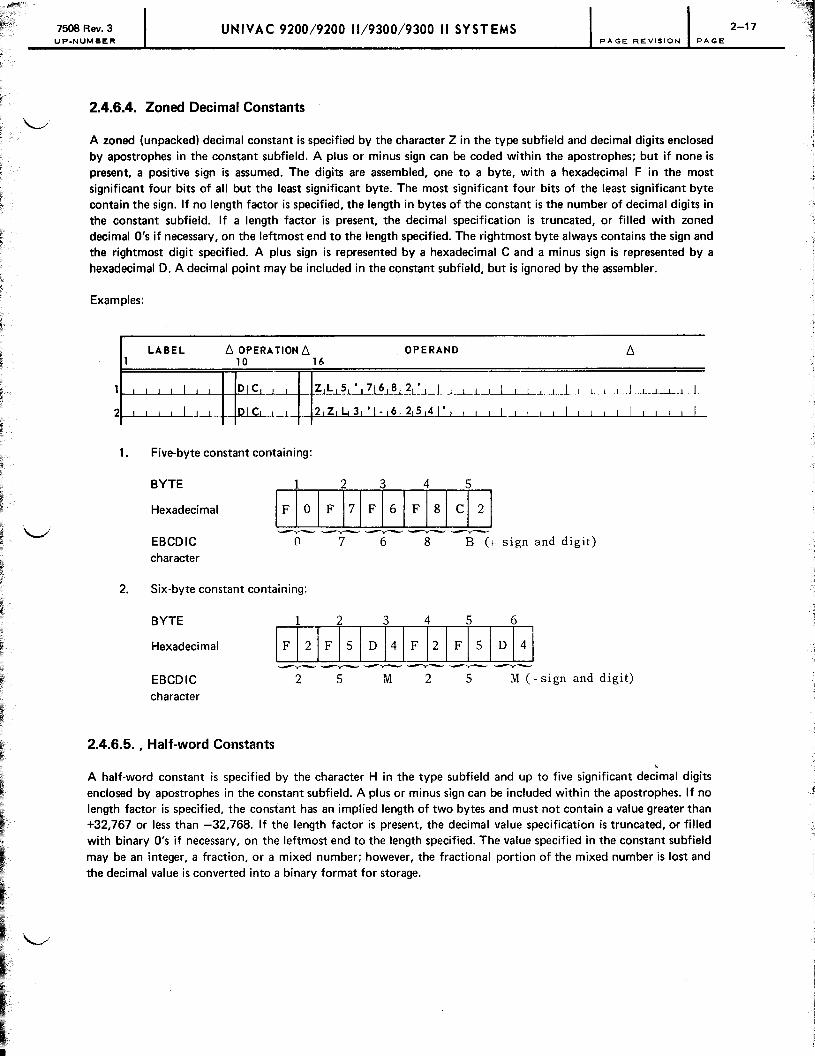
2.4.6.4. Zoned Decimal Constants
A zoned (unpacked) decimal constant is specified by the character Z in the type subfield and decimal digits enclosed by apostrophes in the constant subfield. A plus or minus sign can be coded within the apostrophes; but if none is present, a positive sign is assumed. The digits are assembled, one to a byte, with a hexadecimal F in the most significant four bits of all but the least significant byte. The most significant four bits of the least significant byte contain the sign. If no length factor is specified, the length in bytes of the constant is the number of decimal digits in the constant subfield. If a length factor is present, the decimal specification is truncated, or filled with zoned decimal O's if necessary, on the leftmost end to the length specified. The rightmost byte always contains the sign and the rightmost digit specified. A plus sign is represented by a hexadecimal C and a minus sign is represented by a hexadecimal D. A decimal point may be included in the constant subfield, but is ignored by the assembler.
Examples:
LABEL l:J. OPERA TIOM l:J. OPERAMD 1 10 16
I DIC ZL 5 ,
716 8 2 • I I I
2 I DIC 2 Z L 3 ' I - 6 25 41' I I I I I I I I
1. Five-byte constant containing:
BYTE
Hexadecimal
-......- -----.- ....---....-~ --.-EBCDIC character
o 7 6 8 B (+ sign and digit)
2. Six-byte constant containing:
BYTE 1 2 3 4 5 6
Hexadecimal IFI21FI si D 141F 121 Fisl DI41 ----...- .....--.....--. ~ -......- --.- -..---....-
l:J.
I I
I I I
EBCDIC character
2 5 M 2 5 M (- sign and digit)
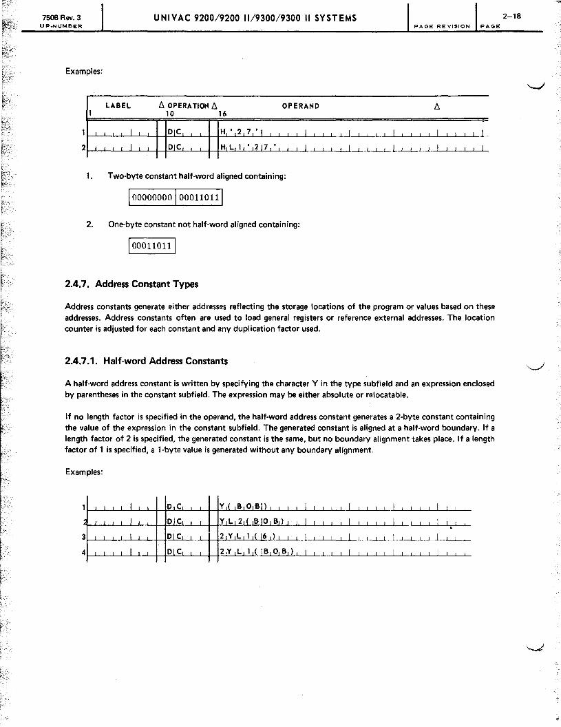
2.4.6.5. , Half-word Constants
I I I I I
I I I I I
A half-word constant is specified by the character H in the type subfield and up to five significant decimal digits enclosed by apostrophes in the constant subfield. A plus or minus sign can be included within the apostrophes. If no length factor is specified, the constant has an implied length of two bytes and must not contain a value greater than +32,767 or less than -32,768. If the length factor is present, the decimal value specification is truncated, or filled with binary O's if necessary, on the leftmost end to the length specified. The value specified in the constant subfield may be an integer, a fraction, or a mixed number; however, the fractional portion of the mixed number is lost and the decimal value is converted into a binary format for storage.
7508 Rev. 3 UP_NUMBER
UNIVAC 9200/9200 11/9300/9300 II SYSTEMS 2-18 PAGE REV'S'ON PAGE
Examples:
LABEL 6. OPERATION 6. OPERAND 6. 1 10 16
, DIC 1 H ',2 7 " , , I I I 1 I I I I I I I I I I I I I I L I DIC H L,l, , ,21 7 I
, , 1 1 I I I I I I I I I I I ! ! I I I I I I I I 2
1. Two-byte constant half-word aligned containing:
1000000001000110111
2. One-byte constant not half-word aligned containing:
1000110111
2.4.7. Address Constant Types
Address constants generate either addresses reflecting the storage locations of the program or values based on these addresses. Address constants often are used to load general registers or reference external addresses. The location counter is adjusted for each constant and any duplication factor used.
2.4.7.1. Half-word Address Constants
A half-word address constant is written by specifying the character Y in the type subfield and an expression enclosed by parentheses in the constant subfield. The expression may be either absolute or relocatable.
If no length factor is specified in the operand, the half-word address constant generates a 2-byte constant containing the value of the expression in the constant subfield. The generated constant is aligned at a half-word boundary. If a length factor of 2 is specified, the generated constant is the same, but no boundary alignment takes place. If a length factor of 1 is specified, a 1-byte value is generated without any boundary alignment.
Examples:
3~~~~~~~~~~J-~~~~~~~~.
4~-L~L-~-L1-~~~~~~~~~~~~~~-L~~~-L~~~-LJ-L-~-L~

7508 Rev. 3 UP-NUMBER
UNIVAC 9200/9200 11/9300/9300 II SYSTEMS 2-19 PAGE REVISION PAGE
The preceding statements generate the following constants. (In each example, it is assumed that BOB has a value of 1446. This value may represent an main storage address or may be a binary value used for arithmetic purposes. The hexadecimal value equal to 1446 is stored as shown.)
1. Two-byte constant, aligned on a half-word boundary, containing:
2. Two-byte constant, unaligned, containing:
3. Two-byte field containing the 1-byte constant duplicated once as:
4. Two-byte field containing the truncated value of BOB duplicated once, as:
2.4.7.2. Base and Displacement Constants
A base and displacement constant is specified by the character S in the type subfield and one or two expressions enclosed by parentheses in the constant subfield. The expressions may be absolute or relocatable. A length factor, if
\..-.I present, can be only 2. If no length factor is specified, the implied length of the constant is two bytes. Negative relocatable values are not permitted. This type of constant is used to store addresses in the base and displacement form; the leftmost four bits represent the base and the remaining 12 bits represent the displacement. If one expression is present, the assembler converts it to a base plus displacement value. If two expressions are present, the expression representing the base is enclosed in parentheses with the other expression (representing the displacement) preceding it and another set of parentheses enclosing the base and displacement specifications. The S-type constants may not be specified as literals. Adjustment to the half-word boundary is made only if no length specification is used.
Examples:
2
3
4
5
LABEL 1
I
~ I
1 i I I t I I
I L t
I
I
J 0 H N I
I
ii J S YIM BIOIL I
SY MBOIL
[:, OPERA TION [:, 10 16
SITART 4 0 9 6 I
I· I
I· I I I I I 1 i_I
UIS liN IG 5 10 0 0 ,j9i
t. t
I. I
I I
I· I
I· I
DIC S ( J o HjN )
DIC S ( 2 5 ( 19 )
OPERAND [:,
1 I I t t
I I t I t
I I j I II I 1 I I i I I I I I I I I I I I I
1 I j Ii ~i I I I
I I t t t
I I I I I
1 I I I I I I I I I I I I I I I I I
I I I I I
I I I t I
I L I _1 iii I t
) I I I I I I I I I I I I I I I I I I I I L.L

7508 Rev. 3 UP.NUMBER
UNIVAC 9200/9200 11/9300/9300 II SYSTEMS PAGE REVISION PAGE
Assume that the constant with the label JOHN (line 3) is assigned an address value of 5025'0 by the location counter, and that the USING directive (line 2) gives the value 5000, 0' which is assumed to be in register 9 at execution time. The operands in the two statements (lines 4 and 5) produce the same stored base and displacement value. The hexadecimal representation of this stored value is 9019 as follows:
1 BYTE
I I
9 I I I
0 I I
... -BASE
REGISTER (4 BITS)
NOTE:
0
1 BYTE
I I
1 I 9 I I
7 8 I 15 ~
DISPLACEMENT (12 BITS)
Refer to 4.4 for a description of the USING directive.
2.4.8. Data Storage Definition Examples
The programmer can reference a data storage area in many ways. By defining an area in terms of its smallest divisions or fields, each field can be referenced. The programmer can then use a OS statement with a O·duplication factor to define a label and give it a length attribute so that more than one field can be referenced simultaneously.
The following example illustrates a typical data storage area and the subdivision of its fields:
c D ----B
E
------------~--~----------------t
where:
A Is a 40·byte field.
B Is a 20-byte field.
C Is a 10-byte field.
0 Is a 10·byte field.
E Is a 20-byte field.
2-20
7508 Rev. 3 UNIVAC 9200/9200 11/9300/9300 II SYSTEMS UP-NUMBER PAGE REVISION PAGE
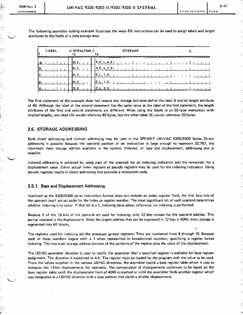
The following assembler coding example illustrates the ways DS instructions can be used to assign labels and length o attributes to the fields of a data storage area:
LABEL [:, OPERA TION [:, OPERAND [:, 1 10 16
A I I DIS o C L 4 0 I I I I I I I
B~ ~ I I I DIS o C L 2 0 I I I I I I
C I DIS C L 1 0 I ..L...L...J.. I I I I I I I I I I I I I I I I I I I I I
D I DIS CL 1 0 I I I I I I I I I I I I I I I I I I I IE I DIS C L 2 0 I I I I I I
The first statement of the example does not reserve any storage but does define the label A and its length attribute of 40. Although the label of the second statement has the same value as the label of the first statement, the length attributes of the first and second statements are different. When using the labels in an SS-type instruction with implied lengths, one label (A) would reference 40 bytes, but the other label (B) would reference 20 bytes.
2.5. STORAGE ADDRESSING
Both direct addressing and indirect addressing may be used in the SPERRY UNIVAC 9200/9300 Series. Direct addressing is possible because the operand portion of an instruction is large enough to represent 32,767, the maximum main storage address available in the system. Indexed, or base and displacement, addressing also is possible.
Indexed addressing is achieved by using part of the operand for an indexing indication and the remainder for a displacement value. Either actual index registers or pseudo registers may be used for the indexing indication. Using pseudo registers results in direct addressing that provides a relocatable code.
2.5.1. Base and Displacement Addressing
Inasmuch as the 9200/9300 series instruction format does not include an index register field, the first four bits of the operand itself are set aside for the index or register number. The most significant bit of each operand determines whether indexing is to occur. If that bit is a 1, indexing takes place; otherwise, no indexing is performed.
Because 4 of the 16 bits of the operand are used for indexing, only 12 bits remain for the operand address. This partial operand is the displacement. Since the largest address that can be expressed in 12 bits is 4095, main storage is segmented into 4K blocks.
The registers used for indexing are the processor general registers. They are numbered from 8 through 15. Because each of these numbers begins with a 1 when represented in hexadecimal notation, specifying a register forces indexing. The true main storage address consists of the contents of the register plus the value of the displacement.
The USING assembler directive is used to notify the assembler that a specified register is available for base register assignment. The directive is explained in 4.4. The register must be loaded by the program with the value to be used. From the values supplied in the various USING directives, the assembler builds a base register table which it uses to compute the 12-bit displacements for operands. The computation of displacements continues to be based on the base register table until the displacement limit of 4095 is reached or until the assembler finds another register which was designated in a USING directive with a base address that yields a smaller displacement.
2-21

7508 Rev. 3 UNIVAC 9200/9200 11/9300/9300 II SYSTEMS
2-22
UP.NUMBER PAGE REVISION PAGE
The SPE RRY UN IVAC 9200/9300 Series Operating System locator/loader routine places the transfer address of a main program in processor register 15 prior to transferring control to the program. The programmer may take .-.......,1 advantage of this fact by coding a USING directive containing the label of the first instruction to be executed and specifying register 15 as the base register, as:
LABEL L10PERA TlONL1 OPERANO 1 to 16
_._.L .. _l " .1. ___ 1 .. _. _ ~L~IIL~_ !EP , N I ' i!J,_5_-'-'--'--'--'--'--. .1.-J'---'~~L~-L_L_...L1 -'--'---~'. --.Ll_~
~J!.I G,N 1 I ___ L _ ~~_L S ~S A I B I L! -L_L-'--'--'---.L.-.J--'---'--'----L---'--'--L-l----'---' __ '--'----1--'---'----'---'!--'--, 1 I , I
L I I I __ f-L.L-LI -,---,--->.1--,-' --1-- ~~L~l~ _-+G...10--,-_' LS--'----'-.l-.L' ...1'--'----'---'--'--L-L' -'1----1----'--'-----'_
GO, MIV C. O,U,T TIWO I I I J
, I I I , L.J.'-L..--L...-'--'--"---,----1'--L.' --1-1 --'---'---'--'--' __ I _____ I--L.--,---,._.--,-._LL
_.L .. _.L-'---'-..L.-JL-LI .. _ .-+-'-.1-...1 _L _ f_LLL---1----LL-'-----l._--',--'--'---'--'-----''--'---'-' -LJ..-'--.' --'-.L-I,--_L-L-L-...1.-L-lI __ -L.-.LL _ I I ,.LL-L _ _~LL --'--.l.-f_+_L-L.L....L_l __ -'--'---'---'--'---l--l----'---'-, ---,1,--,----,---,--,--,--,---"-' ---,.,---,_--,---,--, -,''---'--'-_iLL
J-0--'-U-'--T.L-''---'[--'--'---t_+~_-'--'~J-t--t!!t • ! , ! T ,W,O, I I DIC H,' 2' I
1
I I j 1
In this example, since register 15 was the base register in force at the time, the machine code generated at BEGN J might appear as:
4880FE24
Since the following line declared the availability of register 8 as a base register and since register 8 will now yield a smaller displacement than register 15 for any operands which address locations following GO, the machine code generated at GO might appear as:
D2018E1C8E1E
2.5.2. Pseudo Register Base and Displacement Addressing
True base and displacement addressing requires index register modification of each instruction. Direct addressing is more desirable because it eliminates the extra cycles required to index each instruction, speeding up instruction execution. Direct addressing can be achieved by assembling the program with absolute addresses by using an ORG directive. With this method, however, the program cannot be relocated.
Another type of addressing provides direct addressing and relocatable code, but does not require indexing of each instruction. This form of addressing uses pseudo registers. To designate a pseudo register, the USING directive format is:
LABEL L1 OPERATION 6. OPERAND
USING *,n

7508 Rev. 3 UNIVAC 9200/9200 11/9300/9300 II SYSTEMS UP.NUMBER PAGE REVISION PAGE
where:
n Is the pseudo register number, from 0 through 7.
As in true base and displacement addressing, the pseudo register USING directive provides a value for the base register table. But in this case, the values are not arbitrarily provided as a result of the label processing by the assembler; they are fixed values determined by the register number given in the USING directive. The register numbers 0 through 7 produce the table values:
register 0 - 0
register 1 - 4096
register 2 - 8192
register 3 - 12,288
register 4 - 16,384
register 5 - 20,480
register 6 - 24,576
register 7 - 28,672
When using pseudo registers, the operand displacement is determined in the same way as with actual registers. The displacement for an operand is computed by subtracting the table value that produces the smallest 12·bit displacement from the label value. For instance, if TAG were at address 4100, this value would be shown as:
BASE DISPLACEMENT
0001 000000000100
Viewed as a base and displacement address, this operand shows a base register of 1 and displacement of 4. (Remember that pseudo register 1 is the value of 4096.) The 16·bit address also is the binary representation of 4100: 0001000000000100, the actual address of TAG.
Since the pseudo register numbers range from 0 through 7, the most significant bit is zero. The operand, then, does not cause indexing and, when read as a binary number, is a direct address.
True base and displacement addressing is advantageous only when the programmer must be concerned with later conversion to a processor with a main storage capacity exceeding 32K. Even then the use of pseudo regis'ters may be preferable because the conversion requires reassembling the program, and the USING directives can be changed easily at that time.
2-23

--.::.:

7508 Rev. 3 UNIVAC 9200/9200 11/9300/9300 II SYSTEMS UP.NUMBER PAGE REVISION PAGE
3. Instructions
3.1. GENERAL
The SPERRY UNIVAC 9200/9300 Series Tape/Disc Assembler uses a repertoire of 35 machine instructions, which are described in this section. The instructions are listed in Tables 3-1,3-2,3-3, and 3-4.
NOTE:
The 9200 system is not provided with the divide packed decimal, multiply packed decimal, and edit instructions, except as optional features. If the optional hardware instructions are not installed, they may be simulated by UNIVAC·supplied fixed, closed subroutines, which duplicate the functions of the instructions. The use of the optional hardware instructions does not differ from that of the standard 9300 system instructions. The use of the software subroutines is described in the operational conditions of the instructions (3.3.1.5,3.3.1.6, and 3.3.4.1).
\.......t The instructions are grouped by function in this section, as in Table 3-2. The function types are arithmetic, branch, comparison, data manipulation, data transfer, display, input/output, logical, and supervisor. Each type is analyzed and explained separately. The timing for the instructions is presented in Table 3-4. The symbols used in illustrations in this section are listed in Table 3-5.
r
\ .... /
3.2. INSTRUCTION FORMAT
The machine instruction format consists of an optional label, a mnemonic operation code, and one or two operands.
LABEL !:,. OPERATION!:,. OPERAND
[ symbol 1 code operand 1, operand 2
The label may be any symbol, as previously defined, but its use is not required. The mnemonic operation code for each instruction is specified in Table 3-1 and in the text explaining each instruction. The operands are of two forms, expressions, as previously defined, or complete specifications. Any symbol used in an expression must be defined within the program. A complete specification includes a base register and a displacement value. The specification is explicit and the assembler uses these numbers to compile the addresses of the operands. Each type of operand is illustrated in the example format:
LABEL !:,. OPERATION!:,. OPERAND
[ symbol 1 code
{
D1(L1,B1), D2(L2,B2)}
expression, expression
3-1 1

7508 Rev. 3 UNIVAC 9200/9200 11/9300/9300 II SYSTEMS 3-2
UP.NUMBER PAGE REVISION PAGE
Table 3-1. Instruction Mnemonics
Hexadecimal Mnemonic Function Operation Format
Code
AH Add half word AA RX AI Add immediate A6 SI AP Add (packed) decimal FA SS2 BAL Branch and link 45 RX BC Branch on condition 47 RX CH Compare half word 49 RX CLC Compare logical character D5 SSl CLI Compare logical immediate 95 SI CP Compare (packed) decimal F9 SS2 DP Divide (packed) decimal FD SS2 ED Edit DE SSl HPR Halt and proceed A9 SI LH Load half word 48 RX LPSC Load program state control A8 SI MP Multiply (packed) decimal FC SS2 MVC Move characters D2 SSl MVI Move immediate data 92 SI MVN Move numerics D1 SSl MVO Move with offset F1 SS2 NC AND characters D4 SSl NI AND immediate data 94 SI OC OR characters D6 SSl 01 OR immediate data 96 SI PACK pack F2 SS2 SH Subtract half word AB RX SP Subtract (packed)decimal FB SS2 SPSC Store program state control AO SI SRC Supervisor request call A1 SI STH Store half word 40 RX TIO Test I/O A5 SI TM Test under mask 91 SI TR Translate DC SSl UNPK Unpack F3 SS2 XIOF Execute input/output function A4 SI
ZAP Zero add (packed) decimal F8 SS2

7508 Rev. 3 UP.NUMBER
UNIVAC 9200/9200 11/9300/9300 II SYSTEMS 3-3 PAGE REVISION PAGE
Table 3-2. Instruction Types
Hexadecimal Type Mnemonic Function Operation Format
Code
Arithmetic AH Add half word AA RX AI Add immediate A6 SI AP Add (packed) decimal FA SS2 DP Divide (packed) decimal FD SS2 MP Multiply (packed) decimal FC SS2 SH Subtract half word AB RX SP Subtract (packed) decimal FB SS2 ZAP Zero add (packed) decimal F8 SS2
Branch BAL Branch and link 45 RX BC Branch on condition 47 RX
Comparison CH Compare half word 49 RX CLC Compare logical character 05 SS1 CLI Compare logical immediate 95 SI CP Compare (packed) decimal F9 SS2 TM Test under mask 91 SI
Data ED Edit DE SS1 manipulation PACK Pack F2 SS2
TR Translate DC SS1 UNPK Unpack F3 SS2
Data LH Load half word 48 RX transfer MVC Move characters 02 SS1
MVI Move immediate data 92 SI MVN Move numerics 01 SS1 MVO Move with offset F1 SS2 STH Store half word 40 RX
Display HPR Halt and proceed A9 SI
I/O TIO Test I/O A5 SI XIOF Execute input/output function A4 SI
Logical NC AND characters 04 SS1 NI AND immediate data .94 SI OC OR characters 06 SS1 01 OR immediate data 96 SI
Supervisor LPSC Load program state control A8 SI SPSC Store program state control AO SI SRC Supervisor request call A1 SI

7508 Rev. 3 UP.NUMBER
UNIVAC 9200/9200 11/9300/9300 II SYSTEMS 3-4 PAGE REVISION PAGE
Table 3-3. Instruction Formats
Hexadecimal Format Operation Mnemonic Function
Code
RX 40 STH Store half word RX 45 BAL Branch and link RX 47 BC Branch on condition RX 48 LH Load half word RX 49 CH Compare half word RX AA AH Add half word RX AB SH Subtract half word SI 91 TM Test under mask SI 92 MVI Move immediate data SI 94 NI AND immediate data SI 95 CLI Compare logical immediate SI 96 01 OR immediate data SI AO SPSC Store program state control SI A1 SRC Supervisor request call SI A4 XIOF Execute input/output function SI A5 TIO Test I/O SI A6 AI Add immediate SI A8 LPSC Load program state control SI A9 HPR Halt and proceed
SS1 D1 MVN Move numerics SS1 D2 MVC Move characters SS1 D4 NC AND characters SS1 D5 CLC Compare logical character SS1 D6 OC OR characters SS1 DC TR Translate SS1 DE ED Edit
SS2 F1 MVO Move with offset SS2 F2 PACK Pack SS2 F3 UNPK Unpack SS2 F8 ZAP Zero add (packed) decimal SS2 F9 CP Compare (packed) decimal SS2 FA AP Add (packed) decimal SS2 FB SP Subtract (packed) decimal SS2 FC MP Multiply (packed) decimal SS2 FD DP Divide (packed) decimal
1
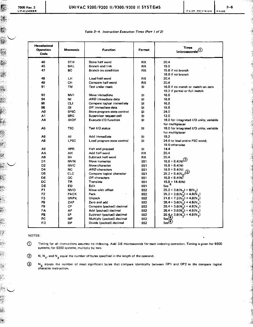
7508 Rev. 3 UP-NUMBER
UNIVAC 9200/9200 11/9300/9300 II SYSTEMS 3-5 PAGE REVISION PAGE
Table 3-4. Instruction Execution Times (Part 1 of 2J
Hexadecimal Times CD Operation Mnemonic Function Format
(microsecondsl ' Code
40 STH Store half word RX 20.4 45 BAL Branch and link RX 1B.0 47 BC Branch on condition RX 15.6 if no branch
18.0 if no branch 48 LH Load half word RX 20.4 49 CH Compare half word RX 20.4 91 TM Test under mask SI 16.8 if no match or match on zero
19.2 if partial or full match 92 MVI Move immediate SI 16.S 94 NI AND immediate data 51 16.S 95 CLI Compare logical immediate SI 16.S 96 01 OR immediate data SI 16.S AO SPSC Store program state control SI 24.0 A1 SRC Supervisor request call SI 12.0 A4 XIOF Execute I/O function SI 1S.0 for integrated I/O units; variable
for multiplexer A5 TIO Test I/O status SI 1S.0 for integrated I/O units; variable
for multiplexer A6 AI Add immediate SI 19.2 AS LPSC Load program state control SI 24.0 to load entire PSC word;
1S.0 otherwise A9 HPR Halt and proceed SI 14.4 AA AH Add half word RX 20.4 AB SH Subtract half word RX 20.4 @ 01 MVN Move numerics SS1 16.S + S.4(NI 2 02 MVC Move character SS1 16.S + 8.4(NI 04 NC AND characters SS1 16.S + S.4(N) @) 05 CLC Compare logical character SS1 25.2 + 8.4(N
fl
06 OC OR characters SS1 16.S + S.4(N DC TR Translate SS1 16.8 + 14.4(N) DE ED Edit SS, See 4 F1 MVO Move with offset SS2 25.2 + 3.6(N21 + 6(N ) F2 PACK Pack SS2 25.2 + 3.6(N21 + 4.S(~ 1) F3 UNPK Unpack SS2 21.6 + 7.2(N21 + 4.S(N,) FS ZAP Zero and add SS2 26.4 + 3.6(N2) + 4.S(N 1) F9 CP Compare (packed) decimal SS2 26.4 + 3.6(N2) + 4.S(N 1) FA AP Add (packed) decimal SS2 26.4 + 3.6(N2) + 4.S(N 1) FB SP Subtract (packed) decimal SS2 26.~ 3.6(N21 + 4.S(N,1 FC MP Multiply (packed) decimal SS2 See 4
FD DP Divide (packed) decimal SS2 See 4
NOTES:
CD Timing for all instructions assumes no indexing. Add 3.6 microseconds for each indexing operation. Timing is given for 9300 systems; for 9200 systems, multiply by two.
@ N, N" and N2 equal the number of bytes specified in the length of the operand.
@) NE equals the number of most significant bytes that compare identically between OP1 and OP2 in the compare logical character i nstructi on.

UN IVAC 9200/9200 11/9300/9300 II SYST EMS
Detailed formulas for the edit, multiply, and divide instructions are:
• Edit (ED)
30 + 682 + 14N + 6(NDS
+ NSS) + 612 + 61 1
• Multiply (packed) decimal (MP)
52 + 13 (N 1 - N2) + (16 + 14N2) LMMD + (22 + 14N2)
L LMD + 24 (NMMDO) + 612 + 61 1 + 14
largest integer ± in
PAGE REVISION PAGE
This term gives an upper and lower limit (note the ± sign) for a specific MP instruction using the actual values of OP1 and OP2. A series of MP instructions executed with random numbers for operands yielded an average execution time of 28 (N 1 - N2)·
Table 3-6 consists of a hardware timing chart that can be used to approximate the times required for multiplication , operations.
• Divide (Packed) decimal (DP)
56 + 8N2 + 6N 1 + (30 + 14N2) L(MOD + 1) + (22 + 14N2) LLOD + 612 + 61 1
where:
NMMDO
LMD
MOD
'OP2'
the number of digit select bytes in OP1 of edit instruction.
the number of significant start bytes in OP1 of edit instruction.
the total number of signs in all the bytes accessed for OP2 of edit instruction.
the value of a nonzero multiplier (OP1) digit positioned in the most significant half of a byte.
the number of zero multiplier (OP1) digits positioned in the most significant half of a byte. The N2 most significant bytes of OP1 are excluded.
the value of a multiplier digit positioned in the least significant half of a byte.
the value of a quotient digit positioned in the most significant half of a byte.
the tens complement of quotient digits positioned in the least significant half of a byte.
multiplicand digits
o if operand 1 is not indexed; 1 if indexed.
o if operand 2 is not indexed; 1 if indexed.
3-6

7508 Rev. 3 UNIVAC 9200/9200 11/9300/9300 II SYSTEMS 3-7 UP.NUMBER PAGE REVISION PAGE
Table 3-5. Instruction Symbols
Symbol Meaning
B1 The number of the general register that holds the base address of operand 1. B2 The number of the general register that holds the base address of operand 2. code The mnemonic operation code of the instruction. 01 The displacement from the base address of operand 1. 02 The displacement from the base address of operand 2. 12 The immediate data used as operand 2 in SI format instructions. L1 The length of operand 1 as stated in source code.* L2 The length of operand 2 as stated in source code.* OP1 Operand 1. OP2 Operand 2. R1 The number of the general register that holds operand 1 in RX format instructions. symbol The expression or symbolic label used as operand 1. tag The expression or symbolic label used as operand 2.
* The length is coded as the true length of the operand, not the length less 1 as required by the object code. The assembler makes the appropriate reduction by 1 when converting source code to object code.
Table 3-6. Hardware Multiply Timing Chart
Multiplicand Digits (OP21
2 3 4 5 6 7 8 9 10 11 12 13 14 15
2 .75 .75 .80 .80 .85 .85 .90 .90 .95 .95 1.00 1.00 1.04 1.04
3 .99 .99 1.04 1.04 1.08 1.08 1.14 1.14 1.19 1.19' 1.23 1.23 1.27 1.27
4 1.65 1.65 1.70 1.70 1.75 1.75 1.80 1.80 1.85 1.85 1.90 1.90 1.95 1.95
5 1.97 1.97 2.02 2.02 2.07 2.07 2.12 2.12 2.17 22.17 2.22 2.22 2.27 2.27
6 2.89 2.89 2.94 2.94 3.00 3.00 3.04 3.04 3.09 3.09 3.14 3.14 3.19 3.19
;: 3.29 Q. 7
9 3.29 3.34 3.34 3.39 3.39 3.44 3.44 3.49 3.49 3.54 3.54 3.59 3.59
.~ 8 4.46 4.46 4.51 4.51 4.56 4.56 4.61 4.61 4.66 4.66 4.72 4.72 4.76 4.76 aI
is .1 9 4.96 4.96 5.00 5.00 5.05 5.05 5.10 5.10 5.15 5.15 5.19 5.19 5.25 5.25 ].
i 10 6.37 6.37 6.42 6.42 6.47 6.47 6.52 6.52 6.57 6.57 6.62 6.62 6.68 6.68 ~
11 6.94 6.94 6.99 6.99 7.04 7.04 7.09 7.09 7.14 7.14 7.19 7.19 7.25 7.25
12 8.61 8.61 8.66 8.66 8.71 8.71 8.76 8.76 8.81. 8.81 8.86 8.86 8.92 8.92
13 9.27 9.27 9.32 9.32 9.37 9.37 9.42 9.42 9.47 9.47 9.51 9.51 9.58 9.58
14 11.19 11.19 11.24 11.24 11.29 11.29 11.34 11.34 11.39 11.39 11.44 11.44 11.50 11.50
15 11.93 11.93 11.98 11.98 12.03 12.03 12.08 12.08 12.13 12.13 12.18 12.18 12.24 12.24
TIME IN MILLISECONDS
NOTE:
The times are averages based on a multiplier conSisting of fives. To find 9300 system times, use half the figure in the chart.
.-.,;

7508 Rev. 3 UNIVAC 9200/9200 11/9300/9300 II SYSTEMS UP.NUMBER PAGE REVISION PAGE
3.2.1. Source Code Instruction Format
Four instruction format types, the RX, SI, SS1, and SS2 are available. The type of data field processed and the type of processing determine the format of the instruction. The RX format is for instructions that process data in fixed lengths and usually involves the use of a general register. The SI format is for instructions that process data immediately specified as one of the operands. SS1 and SS2 formats are for instructions that process data in variable lengths; SS1 is used when the operands are of equal length, and SS2 is used when they are determined independently.
The four instruction format types are shown in Table 3-7.
3.2.1.1. Register and Indexed Storage Operation (RX)
The RX format is used by 4-byte instructions with the form:
LABEL I::,. OPERATION I::,.
[symbol] code
OPERAND
{ Rl, D2('B2)} Rl, tag
The RX format instructions are used to process fixed-length data fields with a length of two bytes. One operand usually specifies a general register. Functions such as branching, comparing, adding, storing, and loading are performed by instructions in this format.
3.2.1.2. Storage and I mmediate Operand Operation (SI)
The SI format is used by 4-byte instructions with the form:
LABEL I::,. OPERA TlON I::,.
[symbol] code
OPERAND
{DlCB1).I2 l symbol,I2 f
The SI format instructions are used to process data one byte in length, using control or additional data contained in the immediate operand. Logical, arithmetic, manipulative, and testing functions are performed by instructions in this format.
3.2.1.3. Storage to Storage Operation (SS1)
The SS1 format is used by 6-byte instructions with the form:
LABEL I::,. OPERATION I::,.
[symbol] code
OPERAND
{ DlCLl,Bl),D2(B2)} symbol,tag
3-8
"~ .::."--,,;
.~ ;;:i '.:;
"s\<.: -",;:~
-~
_£1

7508 Rev. 3 UNIVAC 9200/9200 11/9300/9300 II SYSTEMS . UP_NUMBER PAGE REVISION PAGE
The SS1 format instructions process data of variable length, up to a maximum of 256 bytes, if the operands specify fields of equal length. Functions such as comparing, transferring, and translating are performed by instructions in this format.
3.2.1.4. Storage to Storage Operation (SS2)
The SS2 format is used by 6-byte instructions with the form:
LABEL 6. OPERATION 6.
(symbol] code
OPERAND
{ Dl(L l,Bl),D2(L2,B2)} symbol,tag
The SS2 format instructions process data of variable-length operands, to a maximum of 16 bytes, when the operands are not of equal length. The SS2 format is used with all packed decimal instructions. Functions such as shift operations, pack, and unpack are performed by instructions in this format.
3.2.2. Object Code Instruction Format
The format of the instruction repertoire in object code differs from source-code format. The hexadecimal object-code format is used in the printed listing that accompanies an assembly; the main storage dump also uses the object-code format. This format is illustrated in Table 3-7.
An example of an assembly printout is shown in Figure 3-1.
The object code in the third column of Figure 3-1 for the first instruction in the illustration is ABAOBOOO. The interpretation of the object code is:
AB subtract half-word operation code A OP1 register o not used B register holding OP2 base address 000 OP2 displacement
The object code of the second instruction (line number 004) in Figure 3-1 is interpreted as:
96 OR immediate operation code FB immediate data in OP2 9 register holding OP1 base address 011 OP1 displacement
3-9
-:~

7508 Rev. 3 UNIVAC 9200/9200 11/9300/9300 II SYSTEMS
3-10
UP.NUMBER PAGE REVISION PAGE
Table 3-7. Instruction Object-Code Formats
OPI OP2 --- ~ 10
RX code* ,I, .J><)"B\,I20 02 J BITS
OP2 OPI
10 SI code* ,I, 12 J:I19I20 01 "I BITS
OPI OP2
~------.-~---------~
SSI code* L1 Bl 01 B2 02
0 7 8 15 16 19 20 31 32 35 36 47 BITS
SS2 code* L1 L2 Bl 01 B2 02 0 7 8 11 12 15 16 19 20 31 32 35 36 47 BITS
*Using abbreviations as listed in Table 3-5.
·Using abbreviations listed in Table 3-5.
OBJECT SOURCE
LINE ADDRESS OPERATION LABEL OPERATION OPERAND COMMENTS
NUMBER CODE CODE
9300 SYSTEM ASSEMBLY OF STST DATE 04/15/73 PAGE 001 0001 2000 STST START 8192
0002 USING *,2
0003 2000 ABAOBOOO RX SH 10,0(,11)
0004 2004 96FB9011 SI 01 17(9),X'FB'
0005 2008 D120COO5DOOB SS1 MVN 5(33,12),11(13)
0006 200E F8DD8047F056 SS2 ZAP 71 (14,8),86(14,15)
0007 2014 000000002000 END STST
Figure 3-1. Assembly Listing

",-" ..
7508 Rev. 3 UNIVAC 9200/9200 11/9300/9300 II SYSTEMS UP-NUMBER PAGE REVISION PAGE
The object code of the third instruction (line number 005) in Figure 3-1 is interpreted as:
D1 20 C 005 D 008
move numeric operation code length minus one of the operands register holding OP1 base address OP1 displacement register holding OP2 base address OP2 displacement
The object code for the fourth instruction (line number 006) in Figure 3-1 is interpreted as:
F8 zero and add operation code D length minus one of OP1 D length minus one of OP2 8 register holding base address of OP1 047 OP1 displacement F register holding base address of OP2 056 OP2 displacement
To facilitate understanding of the object-code form of the instructions, each instruction is accompanied by a small box containing information pertinent to the interpretation of the object-code instruction format. Each instruction type, AX, 51, 551, and 552 is in its own object code format, as illustrated in Table 3-7.
The relationship between source- and object-code formats is illustrated for the zero and add packed decimal instruction (3.3.1.9):
INSTRUCTION TYPE
SS2
MNEMONIC OPERATION
CODE
ZAP
SYMBOLIC SOURCE CODE OPERAND FORMAT
HEXADECIMAL OPERATION
CODE
F8
OBJECT INSTRUCTION
LENGTH
6 BYTES
BYTES
BITS
The box that accompanies each instruction provides the programmer: the hexadecimal operation code, as F8 for ZAP; the format type, 552 in the example; the number of bytes the instruction will occupy in main storage, six bytes, in the example; and the mnemonic operation code, ZAP.
3-11
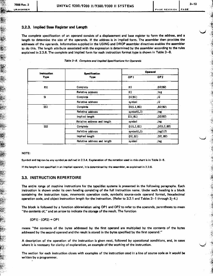
7508 Rev. 3 UNIVAC 9200/9200 11/9300/9300 II SYSTEMS PAGE REVISION PAGE
3.2.3. Implied Base Register and Length
The complete specification of an operand consists of a displacement and base register to form the address, and a length to determine the size of the operands. If the address is in implied form. The assembler then provides the addresses of the operands. Information supplied in the USING and DROP assembler directives enables the assembler to do this. The length attribute associated with the expression is determined by the assembler according to the rules explained in 2.3.6. The complete and implied form for each instruction format type is shown in Table 3-8.
Table 3-8. Complete and ImplltJd Specification, for Operand,
Instruction Specification Operand
Type Type OPl OP2
RX Complete R1 ,02(82)
Relative address R1 ,tag
SI Complete 01(B1) ,12
Relative address symbol ,12
SSl Complete 01(Ll,B1) ,02(62)
Relative address symbol(L1) ,tag
Impl ied length 01(,81) ,02(82)
Relative address and length symbol ,tag
SS2 Complete 01(Ll,81) ,02(L2,B2)
Relative address symbol(Ll) ,tag(L2)
Implied length 01(,81) ,02(,B2)
Relative address and length symbol ,tag
NOTE:
Symbol and tag can be any symbol,as defined in 2.3.4. Explanation of the notation used in this chart is in Table 3-5.
If the length is not specified in an implied operand, it is determined by the assembler, as explained in 2.3.6.
3.3. INSTRUCTION REPERTOIRE
The entire range of machine instructions for the tape/disc systems is presented in the following paragraphs. Each instruction is shown under its own heading consisting of the full instruction name. Under each heading is a block containing the instruction type, mnemonic operation code, symbolic source-code operand format, hexadecimal operation code, and object instruction length for the instruction. (Refer to 3.2.1 and Tables 3-1 through 3;-4.)
The block is followed by a function abbreviation using OP1 and OP2 to refer to the operands, parentheses to mean "the contents of," and an arrow to indicate the storage of the result. The function .
(OP1) . (OP2) -+ OP1
means "the contents of the bytes addressed by the first operand are multiplied by the contents of the bytes addressed by the second operand and the result is stored in the bytes specified by the first operand."
A description of the operation of the instruction is given next, followed by operational conditions, and, in cases
3-12
v-
where it is necessary for clarity of explanation, an example of the working of the instruction. \~
The section for each instruction closes with examples of the instruction used in a line of source code as it would be written by a programmer.

"-":
7608 Rev; 3 UP.NUMBER
UNIVAC 9200/9200 11/9300/9300 II SYSTEMS
3.3.1. Arithmetic Instructions
PAGE REVISION PAGE
The arithmetic instructions add, subtract, multiply, or divide values stored in main storage, in registers, or in immediate operands.
The arithmetic instructions include:
Mnemonic Function Format
AH Add half word RX AI Add immediate SI AP Add packed decimal SS2 DP Divide packed decimal SS2 MP Multiply packed decimal SS2 SH Subtract half word RX SP Subtract packed decimal SS2 ZAP Zero and add packed decimal SS2
The formats of the arithmetic instructions vary with the function of the instruction and the type of data operated upon. The result of the execution of the instruction is stored in the first operand of each instruction. The condition code is changed by most of the arithmetic instructions; the exceptions to this are the divide packed decimal and multiply packed decimal. The operands are processed from left to right in most instructions; the exceptions are the packed decimal instructions. The instructions are explained separately in the text and are accompanied by notes on their limitations and operations.
3.3.1.1. Overflow
Binary arithmetic instructions set the condition code after execution. A condition code setting of 3 denotes that overflow occurred during execution of the instruction. Overflow is a condition occurring when the sign of a numeric field, expressed in binary format, is changed erroneously. The sign change can occur when an attempt is made to develop a larger number than can be expressed in 15 bits. Because all binary data must fit into two bytes, one bit of which must be the sign, the maximum expressible numbers are +32,767 and -32,768.
Example:
OP1 0010101101101000
t. C+ 11,112)
Sign
0101010010011000 C+ 21,656)
t plus OP2
Sign
Result 1000000000000000
t C· 32,768)
Sign
An add half·word instruction using the foregoing operands, by adding OP2 to OP1, results in a number, stored in OP1, of -32,768 instead of the true answer +32,768. The true answer does not fit in 15 bits and the sign bit is changed by execution of the instruction.
3-13
--:1 , {
---i
j .',j
1 !
I j i
·1
j

UNIVAC 9200/9200 11/9300/9300 II SYSTEMS 7508 Rev. 3 UP-NUMBER PA GE RE VISION PAGE
3.3.1.2. Add Half Word
INSTRUCTION MNEMONIC SYMBOLIC SOURCE CODE HEXADECIMAL OBJECT
TYPE OPERATION OPERAND FORMAT OPERATION INSTRUCTION CODE CODE LENGTH
RX AH R1,02(,B2) AA 4 BYTES
Function:
(R1) + (OP2) -+ R1
Description:
Execution of the add half-word instruction adds the contents of the half word specified by OP2 to the contents of the register specified by R 1 ; the result is stored in R 1.
Operational conditions:
1. The OP2 address should be defined at a half-word boundary.
2. The condition code is set as follows:
o Result is zero. 1 Result is negative. 2 Result is positive. 3 Overflow occurred.
Examples:
LABEL /::, OPERATION /::, OPERAND /::, COMMENTS 1 10 16
I AIH 8 1"4d,,II,4d, , I , , , , IC,O,M,P,LIE,T~S IP,E,C,I ,FII ,C,A,T,. 1°,101, , , I AIH ~~L!L~L...L...LLL_l_.L.L-.L~ E, L, A, TI.~ ,AID ,0, R, E'~~l L_l...._L_L_.L.......L..l
3.3.1.3. Add Immediate
INSTRUCTION MNEMONIC SYMBOLIC SOURCE CODE HEXADECIMAL OBJE'CT
TYPE OPERATION OPERAND FORMAT OPERATION INSTRUCTION CODE CODE LENGTH
SI AI °1(B1),12 A6 4 BYTES
Function:
(OP1) + 12 -+ OP1
Description:
Execution of the add immediate instruction adds the binary value specified by the immediate operand, 12, to the contents of the half word specified by OP1; the result is stored in OP1. The immediate operand may be written in any of several forms. (See examples.)
3-14

7508 Rev. 3 UPoNUMBER
UNIVAC 9200/9200 11/9300/9300 II SYSTEMS PAGE REVISION PAGE
Operational conditions:
1. The most significant bit of the immediate operand is treated as a sign in a binary field. The 12 field is sign-extended by the hardware before execution of the instruction. Specifying a negative value for 12 results in OP1 being decremented by that value.
2. The OP2 address should be defined at a half-word boundary.
3. The condition code is set as follows:
0 Result is zero. 1 Result is negative. 2 Result is positive. 3 Overflow occurred.
Examples:
LABEL LlOPERATION6 OPERAND COMMEI\ 10 16
.. i l LL1-L Al!...L..L.;2.L~L'L~LIL,tb~.L lLL-'-_" :C::IQl"" __ l~~LLl;lTII;.L...LSLP;I;;C" d:lllC::.~lTj Ij.Q~N,
. .l ...... L.'-LL1~.Pl .1 .. 1 BLAL~Ll"ulxJ·13.3.l·.: __ ."LLLIR __ LI;Ll,l.o..TJLVLEl "~lD.:tI;ltlE:LSL~, .. : 1 j j j I.
~L .. .LL.L.l .. .1. f-. ~ll.J ..... L..L f-- B.J Al~.lI".1..!.l.=l:ZL .. L.J......L __ L_LJ ....... L~.L j.o.:rJ!J.~l;l.~ __ lP..l [)1.I'II.I;J1.lLl ...... L .... 1 .. 1 .. L ., __
3.3.1.4. Add Packed Decimal
INSTRUCTION MNEMONIC SYMBOLIC SOURCE CODE HEXADECIMAL OBJECT
TYPE OPERATION OPERAND FORMAT OPERATION INSTRUCTION CODE CODE LENGTH
SS2 AP D1 (LbB1),D2(L2 ,B2) FA 6 BYTES
Function:
(OP1) + (QP2) -+ OP1
Descri ption :
Execution of the add packed decimal instruction causes the algebraic addition of the bytes specified by OP1 to the bytes specified by OP2. The result is stored in OP1. Both OP1 and OP2 should contain packed decimal fields.
Operational conditions:
1. Operands are processed from right to left.
2. If OP1 is shorter than OP2, the excess digits of OP2 are ignored; if OP2 is shorter than OP1, zeros are assumed to extend OP2.
3-15
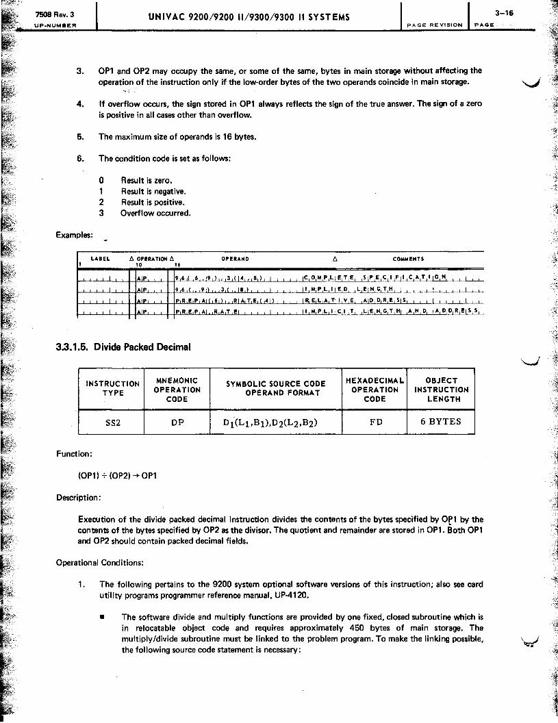
7508 Rev. 3
UP.NUMBER UNIVAC 9200/9200 11/9300/9300 II SYSTEMS
PAGE REVISION PAGE
3. OP1 and OP2 may occupy the same, or some of the same, bytes in main storage without affecting the operation of the instruction only if the low·order bytes of the two operands coincide in main storage.
4. If overflow occurs, the sign stored in OP1 always reflects the sign of the true answer. The sign of a zero is positive in all cases other than overflow.
5. The maximum size of operands is 16 bytes.
6. The condition code is set as follows:
o 1 2 3
Result is zero. Result is negative. Result is positive. Overflow occurred.
Examples:
LABEL t:,. OPERA TION t:,. OPERAND t::. COMMENTS 1 10 16
I AlP 9 6 ( 6 .. 9 ) , 3 (14 , 8 ) I Ie ° hi P LI E T E SIPECIFII CATlloH ,
I AlP 96,( 911" ,3,! ,.18,1, , , I , , ~hI,P,L,IIE,O, ,L~G.cI,H, I , ,~, , , I , , I AlP PRE P AI ( 6,) RIATE,(41) IRELATIIVE AID ORE SI S I I
I AlP PRE P AI RAT EI I II hi P L IIC I T LIENGTHI,A,N,O, IA,O,O,R,EIS,S,
3.3.1.5. Divide Packed Decimal
INSTRUCTION MNEMONIC SYMBOLIC SOURCE CODE HEXADECIMAL OBJECT
TYPE OPERATION OPERAND FORMAT OPERATION INSTRUCTION CODE CODE LENGTH
SS2 OP Oi(Lt.B l),02(L2,B2) FO 6 BYTES
Function:
(OP1) + (OP2) ~ OP1
Description:
Execution of the divide packed decimal instruction divides the contents of the bytes specified by Or1 by the contents of the bytes specified by OP2 as the divisor. The quotient and remainder are stored in OP1. Both OP1 and OP2 should contain packed decimal fields.
Operational Conditions:
1. The following pertains to the 9200 system optional software versions of this instruction; also see card utility programs programmer reference manual, UP·412O.
• The software divide and multiply functions are provided by one fixed, closed subroutine which is in relocatable object code and requires approximately 450 bytes of main storage. The multiply/divide subroutine must be linked to the problem program. To make the linking possible, the following source code statement is necessary:
3-16
--, ~

7508 Rev. 3 , UP.NUMBER
UNIVAC 9200/9200 11/9300/9300 II SYSTEMS PAGE REVISION PAGE
• The source code necessary to accomplish the instruction is:
LABEL /1 OPERA 1101'1 /1 OPERAND 10 16
• The software version of the instruction differs in that:
·OP1 length must be defined in the instruction; the length is not determined by the recoghition of a sign in the field.
Maximum length of OP2 is eight bytes.
A divide check error in the software version causes a display of 29EE.
2. Operands are processed from right to left.
3. The length provided for OP1 must be large enough to accommodate both the quotient and a remainder. If the length provided is not sufficient, the answer is unreliable and bytes beyond OP1 may be affected by the execution of the instruction.
A formula for determining a sufficient length for OP1 is:
L=d+v
where:
L = length of OP1 in bytes. d = length of the dividend and sign in bytes (minimum of 2). v = length of the divisor and sign in bytes. All fractions rounded to the next higher integer.
This formula yields a length that meets or exceeds the requirements of the instruction.
4. Both dividend and divisor must be right·justified in their respective fields; leading zeros must fill the fields.
5. At least one leading zero must precede the dividend. The absolute value of the divisor must be larger than the absolute value of the L2 most significant bytes of OP1. If these requirements are not met, a decimal·divide exception occurs and the processor halts.
6. OP2 and OP1 cannot overlap in main storage.
7. OP2 cannot exceed 16 bytes.

7508 Rev. 3
P-NUMBER
UNIVAC 9200/9200 11/9300/9300 II SYSTEMS 3-18
PAGE REVISION PAGE
8. After execution, OP1 contains the quotient right-justified in the most significant bytes. Its length equals L1 minus L2 bytes. The remainder, if any, is right-justified in the least significant bytes of OP1; the '...J length of the remainder equals L2. Leading zeros pad the quotient and the remainder.
9. The sign of the quotient is determined by the rules of algebra. The sign of the remainder is the same as the sign of the dividend.
2
3
4
5
6
7
8
10. If a quotient digit greater than 9 is formed, a divide-check error occurs and the processor halts.
11. Division by zero produces a decimal-divide exception.
12. Execution of the instruction does not change the condition code setting.
13. An example of the use of the instruction is:
LABEL fj, OPERATION fj, OPERAND fj, 1 10 16
DI V D I DI S CL 1 0 I I I , I I 11 1 DSOR I DIS .1
CL4 I I I I I L
I I I : I , , , , , I , , I , I , , I I , , , I , I
.11 , I ZIA P DII V D , IN U M 1, I , I I , I I
, I J , IzlA,P , D.1S O,R, lNJU, M 2 I I I li' I
I 1 DIP D I V D , ID S 0 R I I I I 1
I MIV C OUT 1 I (16 ) D IIV D I I I I I I I I I I I I , I , I I Mlv C OUT2,CI4,) DIIVD+6 I I I I
In the sample source code, two storage areas labeled DIVD and DSOR are defined in lines 1 and 2. After processing of the problem program, data is moved to the storage area in lines 4 and 5. For the example, DIVD now contains the number:
00 00 00 00 99 03 05 07 00 1 +
DSOR contains the divisor:
03 00 04 0+
Execution of the divide instruction, as coded in line 6, stores the quotient and the remainder in DIVD: ~
00 00 03 30 05 7+ 02 02 72 1 +
The quotient is right-justified in the most significant bytes of DIVD, and the remainder is right-justified in the least significant bytes. The remainder always occupies the same number of bytes as OP2.
In the rest of the example coding, the result of the division is moved to separate data fields.

7508 Rev. 3 UNIVAC 9200/9200 11/9300/9300 II SYSTEMS UP.NUMBER PAGE REVISION PAGE
Examples:
LABEL b. OPERA liON b. OPERAND COMMENTS 10 16
t-'--'-'-.-L...~I-"----i--t"ID"-'IIP-'-'-.....1-t-t'D,-,~J..ll..LQ.dl,!DIIJS,R,(,41)' I L I IRjE,L,A,TII,V,E j ,AjO,D,R,E,S[S,! I! I!!, I I I!
I lDlPL Dd V OLLDS.,Q,R, I, ,I, 1l,t.\p,L,llc,I,T, ,LIE,N,G,T,HI ,A,N,D, IA,D,~&.!=~
f-L--'----1.--'---L..L 1-'---4-+-.Ll..J.......L-I-+ 1--'--'-'-.L..L1--'---L....L...L.....L1--'---.L.....L--,--,1-L...L..L--,----1LL.....L.....L--L.L I . .L.L.L.....L I , , , , I , , , , I , , L tl . ...L-L
3.3.1.6. Multiply Packed Decimal
INSTRUCTION MNEMONIC SYMBOLIC SOURCE CODE HEXADECIMAL OBJECT
TYPE OPERATION OPERAND FORMAT OPERATION INSTRUCTION CODE CODE LENGTH
SS2 MP D1 (L1,B1),D2(L2 ,B2) Fe 6 BYTES
Function:
(OP2) . (OP1) ~ OPl
Description:
Execution of the mUltiply packed decimal instruction multiplies the contents of the bytes specified by OP2, the multiplicand, by the contents of the bytes specified by OP1, the multiplier. The result is stored in OP1. Both OP1 and OP2 should contain packed decimal fields.
Operational Conditions:
1. The following pertains to the 9200 system oPtional software versions of this instruction; see also card utility programs programmer reference manual, UP-4120.
• The software multiply and divide functions are provided by one fixed, closed subroutine in relocatable object code requiring approximately 450 bytes of main storage. The multiply/divide subroutine must be linked to the problem program. To make linking possible, the following source code statements are necessary:
The source code necessary to perform the instruction is:
3-19

75()8Rev.3 UP.NUMaa:R·
UNIVAC 9200/9200 11/9300/9300 II SYSTEMS PAGE REVISION PAGE
• The software version of the instruction differs in that:
OP1 length must be defined in the instruction; the length is not determined by the recognition of a sign in the field.
Maximum length of OP2 is eight bytes.
The multiplier is OP2, and the multiplicand is OP1 in the software version of the instruction. The result is still stored in OP1.
2. Operands are processed from right to left.
3. The length provided for OP1 must be equal to the number of bytes specified for OP2, plus the number of bytes needed to express the multiplier. The multiplier cannot be longer than L 1 minus L2.
4. Zeros must fill the leftmost bytes of OP1.
5. Any excess length of the multiplier in OP1 will be ignored during execution.
6. The sign positions of both operands must contain values greater than nine.
7. The sign of the result is determined in accordance with the normal algebraic rules.
8. The maximum length of OP2 is 16 bytes.
9. OP1 and OP2 cannot overlap in main storage.
10. Failure to meet the requirements results in an unreliable product, but does not set an error indication. The bytes beyond OP1 can be affected by execution of the instruction unless the requirements are met.
11. Execution of the instruction does not change the condition code setting.
12. An example of the use of the mUltiply packed decimal instruction follows:
To multiply 800 by -80, the multiplier would be
08 00
OP2, the multiplicand, would be
80 OF
To fulfill the requirements of the instruction, OP1 contains the multiplier and a numbe~ of bytes equal to OP2. The total four bytes look like
00 00 08 00
After execution OP1 contains
00 64 00 00
3-20

7508. Rev. 3 UNIVAC 9200/9200 11/9300/9300 II SYSTEMS PAGE REVISION PAGE
Examples:
LABEL t:. OPERATION t:. OPERANO t:. COMMENTS 1 10 16
I "'IP 4 1 ( 4 19 )~!.lLt~!'Qlh~--Ll~8.~l"-,-I-J.S'l"LEL ~-.lPJ5SI-,~i!jC~~.L 1 l_L_J
1 MIP -L-L _W~J<Ji~jl~L~lC.~L __ d_ -L_LL' _LRjE,I".,A, Til LVLEL,"J!>.,D,R,E,SJS L' _Lj.lJ. -' .L , I , l
I MIP WEX,LIER 1 1 -L..J.~~,IIC,I,T, ,LIE,N,G,T,HI IAINIDI IA,D,D,R,EIS,~
I 1 1 1 ~-'_L_L_L_LL-L I , , , , 1 '~~~~~LL~j~
3.3.1.7. Subtract Half Word
INSTRUCTION MNEMONIC SYMBOLIC SOURCE CODE HEXADECIMAL OBJECT
TYPE OPERATION OPERAND FORMAT OPERATION INSTRUCTION CODE CODE LENGTH
RX SH RbD2(,B2) AB 4 BYTES
Function:
(Rl) - (OP2) ~Rl
Description:
Execution of the subtract half-word instruction subtracts the contents of OP2 from the contents of R 1. The result is stored in R 1.
Operational conditions:
1. The OP2 address should be defined at a half-word boundary.
2. The condition code is set as follows:
Examples:
o Result is zero. 1 Result is negative. 2 Result is positive. 3 Overflow occurred.
1---'---L-'-L-JILL-L+-f'S--,-ILH!L-'LL-+-+,-,1 '-".4LL.J.! ,0 I ( , ' , I, 1,) i 'L-L...lC..L~~L~..e-'-!L~~<:J......L~1!..l<:..L~!ll~LN.L L"
I--'--,--,---,---,I-,--,-+-I"'S--,-,-, LH'--L--'---t-_+--,-,l '-04,-,-,-,-,F,-,--,-I-,-, IS~C",-,A=--L-L'---'-~ . ..L~-1EbA.LT 11-1 '! , ~L.LA 1 0 l~R~l ~l~_.L_LLLL_LL_-1
f---J-_-'--'-L-'ILL-L-+-I--'---IL.J.-'-+-~'--'--'--'-L-ILL-L.J...--'IL-L, -',~-'-'_.L_LL_L_L-L_L_L..L_'_ _1.._L LL..L_L_L.l._L L L_L~ __ l _J
3-21
-I ~ 1

UNIVAC 9200/9200 11/9300/9300 II SYSTEMS P.NUMBER PAGE REVISION PAGE
3.3.1.8. Subtract Packed Decimal
INSTRUCTION MNEMONIC SYMBOLIC SOURCE CODE HEXADECIMAL OBJECT
TYPE OPERATION OPERAND FORMAT OPERATION INSTRUCTION CODE CODE LENGTH
SS2 SP 01 (L1 ,B1 ),02(L2 ,B2) FB 6 BYTES
Function:
(OP1) - (OP2) 4- OPl
Description:
Execution of the subtract packed decimal instruction subtracts algebraically the bytes specified by OP2 from the bytes specified by OP1. The result is stored in OP1. Both OPl and OP2 should contain packed decimal fields.
Operational conditions:
1. The operands are processed from right to left.
2. If OPl is larger than OP2, zeros are assumed to extend OP2. If OP2 is larger than OP1, the remaining digits of OP2 are ignored.
3. OP2 and OPl may occupy some, or all, of the same bytes in main storage without affecting execution of the instruction only if the low-order bytes of the operands coincide in main storage.
4. If overflow occurs, the sign stored in OPl will reflect the sign of the true result. The sign of a zero is always positive, except in overflow conditions.
5.
6.
Examples:
I
The maximum size of operands is 16 bytes.
The condition code is set as follows:
o Result is zero. 1 Result is negative. 2 Result is positive. 3 Overflow occurred.
LABEL !::. OPERATION !::. 10 16
I SIP, 7
OPERAND
3, ( 6 11 0,) 716 ( 3 110
I SI P 7 3, ( " 1110,)" 17,61(~-L
)
I ,
I sip H,R,S,W,KI{ ,6,) " ,HIR,S,O, U,( 13,) ,
I SiP H R S W KI H R S OIU, , , , I , ,
!::. COMMENTS
C OIM P L E TI E S P E, C I F I CIA T I () HI I
,I,MIP,L,I,E,DI IL, E,H,GIT,H, , , I , , , , I , , ,-->--.L... ,R,EIL,A,T,I,VIE, ,A,D,DI R, E,S,S , I , , , ,
I , , , ,
,I,MIP,L,I,C,IIT, ,L, E,H I G, TIH, ,AIH,D, ,A,DID,R,E,S 51
3-22
-.,:

7508 Rev. 3 UNIVAC 9200/9200 11/9300/9300 II SYSTEMS UP·NUMBER "'AGE REVISION PAGE
3.3.1.9. Zero and Add Packed Decimal
INSTRUCTION MNEMONIC SYMBOLIC SOURCE CODE HEXADECIMAL OBJECT
TYPE OPERATION OPERAND FORMAT OPERATION INSTRUCTION CODE CODE LENGTH
SS2 ZAP 01 (L1,B1),02(L2 ,B2) F8 6 BYTES
Function:
o ~ OP1; (OP2) ~ OPl
Descri pti on :
Execution of the zero and add packed decimal instruction clears the bytes specified by OPl to zero and stores the contents of the bytes specified by OP2 in OP1. To avoid unpredictable results, OP2 should contain a packed decimal field; no restriction is placed on OPl because its contents are overlaid by execution of the instruction.
Operational conditions:
1. Operands are processed from right to left.
2. If OPl is larger than OP2. the excess positions of OPl will be zero filled. If OP2 is larger than OP1, the most significant bytes of OP2 are ignored.
3. OPl and OP2 can overlap in main storage only if the rightmost byte of OPl coincides with, or lies to the right of. the rightmost byte of OP2.
4. If the same field is designated as both OPl and OP2, the field remains unchanged.
5. The maximum size of operands is 16 bytes.
6. The condition code is set as follows:
Examples:
o OP2 is zero. 1 OP2 is negative. 2 OP2 is positive.
LABEL t:. OPERA nON t:. 10 16
OPERAND COMMENTS
I Z~AP 4,1,(,1,4\.,8,),,,816,(,1,4,,11,5,),, IC,O,M,P,LIE,T,E, ,S~I---tflhc,A,T,llo,N, ,I, ,
r-'--'-'-'---'I---'----'---\-t=Z"-IA='-PL-J..-+-t-'-'4~81)",8,6,(I"I,5,), I", II,M,P,L,I~~I)~J.£JI'I~ttLlL.L ,I, ,~-'--'
r-'-~-L-'--' I-'-t---r~-'- ~E-,-)lJh.LL!.L.4~~~~~~E~TlI,~~-,-R, E S l~Ll~J._Ll--'ul . .L L
1-'--'-l......L......Il---'----'-\--+'Z..L"'-"A,PL-J..+-t'H"-"'"E--'YL!B<LLl.I--"E'-"R"-"1G-"'E=RL~_'____L...l, , , , II ,M.P·b!1f.J-LT-'-.L~1~.L~J~Al~~J~p"R~E1SJ.SL

750BRev.3 UP-NUMBER
UNIVAC 9200/9200 11/9300/9300 II SYSTEMS 3-24 PAGE REVISION PAGE
3.3.2. Branch Instructions
Flexibility of program coding is provided with the branch instructions. Used after an instruction that changes the condition code setting, the branch instructions test the condition code and change the coding path according to the programmer's intentions. The branch and link instruction affords the additional device of allowing the program to return to the starting point of the varying path. The branch instructions are:
Mnemonic
BAL Be
Function
Branch and link Branch on condition
Format
RX RX
The assembler affords extended mnemonic codes as shorthand symbols to facilitate the writing of branch instructions. The extended mnemonic codes are listed in Table 3-9. All of these codes represent the branch on condition instruction with different code settings in the R1 field of the instruction format.
The branch on condition instruction tests the condition code setting but does not change it. The branch on condition and branch and link instructions are explained separately in the text and are accompanied by notes on their limitations and operations.
3.3.2.1. Branch and Link
INSTRUCTION MNEMONIC SYMBOLIC SOURCE CODE HEXADECIMAL OBJECT
TYPE OPERATION OPERAND FORMAT OPERATION INSTRUCTION CODE CODE LENGTH
RX BAL RbD2(,B2) 45 4 BYTES
Function:
Branch to OP2; store address at R 1
Description:
The branch and link instruction affords an unconditional branch to the address specified by OP2
Operational conditions:
1. Because the OP2 address is accessed first during execution of the instruction, no conflict is inherent in specifying the same register for R 1 that is used as a base register in the indexed address of OP2. ~
2. Execution of the instruction does not change the condition code setting.
Examples:
LABEL D. OPERA TlO~ D. OPERAND D. COMMENTS 1 10 16
I BIA L 8 8 0 (l. 1 1,1 I IC 0 M P Lj Et T E, ~I EIC i 1 I Fill CI AI Til 101 I'll I
I BlA L 8 R TI FII II I'I I I I I I I IRIEILIA~~IDIDIRIEISISI I I I I I I l_

7508 Rev. 3 UPoNUMBER
UNIVAC 9200/9200 11/9300/9300 II SYSTEMS 3-25 PAGE REVISION PAGE
" 3.3.2.2. Branch on Condition V
INSTRUCTION MNEMONIC SYMBOLIC SOURCE CODE HEXADECIMAL OBJECT
TYPE OPERATION OPERAND FORMAT OPERATION INSTRUCTION CODE CODE LENGTH
RX Be Rl,D2(,B2) 47 4 BYTES
Function:
If match branch to OP2
Description:
Execution of the branch on condition instruction tests the condition code setting with the mask specified by the R1 bits, and, if the test is met, a branch to the address specified by OP2 is executed. If the test is not met, the next instruction in sequence after the branch instruction is executed.
Operational conditions:
1. Each 1 bit in the R 1 mask tests one of the four possible condition code settings. More than one bit can be used in the mask to test more than one condition code; the branch to the OP2 address occurs if one or more of the conditions is present.
Condition Code R1
0 8 4
2 2 3
2. If R1 is zero, the result is a NO-OP; if R1 is 15, the result is an unconditional branch to the OP2 address.
3. Execution of the instruction does not change the condition code setting.
Examples:
LABEL 6 OPERATION 6 OPERAND 6 COMMENTS 1 10 16
---"-.-'--L-L~_L L_ . ~1~.1- .1.... 8"
.LL_1.l()L<'.l'L1 j-4-,.U 1 ."- 1 .1 1.'=,0 LM,f', L lE L T, E.L-,Sl~.L~lC,1 iF LI,C"AL 1} ]0, N .1.-'-,
.......L--,--,--,--.L . .L..l Bl c:;" 1 1 8 11 'PL ReOI BJ AL LI I , , , 1 jRjE,L1A,Tjl j V,E1 lA!D,D,RiE"SLSj , j j ] 1 j 1 1
I BI~Lf-- hl..LL.l!'lill X , T, I , 1~_LL..L.i..U.L~~,0J.NlD11-,-TII.lQl~I~-,-~~~,N, C,Hl L.LLL
I -'- B'C -'---'. I-- <1.J.~.'!~'~-'--.l .. -,-_-,-_~I.l!",.J _" .. -'- .. 1...1 _L.LL.L.-,---Ll _1...1 .. 11 .1..L---'.-'.

7508 Rev. 3 UNIVAC 9200/9200 11/9300/9300 II SYSTEMS 3-26 PAGE REVISION PAGE
3.3.2.3. Extended Mnemonic Codes
The extended mnemonic codes use the following format:
LABEL 6. OPERATION 6. OPERAND
[symbol] code
where:
code Is any mnemonic as listed in Table 3-9.
Is an address, either complete specification or relative form.
Table 3-9. Extended Mnemonic Codes
Hexadecimal
Mnemonic Function Operation Rl Format
Code
B Branch 47 F RX NOP No operation 47 0 RX
Used After Comparison Instructions
BH Branch if high 47 2 RX BL Branch if low 47 4 RX BE Branch if equal 47 8 RX BNH Branch if not high 47 D RX BNL Branch if not low 47 B RX BNE Branch if not equal 47 7 RX
Used After Test Under Mask Instructions
BO Branch if all ones 47 1 RX BZ Branch if all zeros 47 8 RX BM Branch if mixed 47 4 RX BNO Branch if not all ones 47 E RX BNZ Branch if not all zeros 47 7 RX BNM Branch if not mixed 47 B RX
Used After Arithmetic Instructions
BO Branch if overflow 47 1 RX BZ Branch if zero 47 8 RX BM Branch if minus 47 4 RX BP Branch if positive 47 2 RX BNO Branch if no overflow 47 E RX BNZ Branch if not zero 47 7 RX BNM Branch if not minus 47 B RX BNP Branch if not positive 47 D RX
The format is a variation of the RX instruction format. The assembler uses the extended mnemonic to form both the operation code and the R 1 field of the instruction.
Examples:
LABEL t, OPERATION t, OPERAND t, COMMENTS 1 10 16
I -1._ I- ~l!:iLLl 214 , I, ( LLUl 6,) 1--'-~ -'--'-_.L--l_lfL9.l'!l_'-"'-'l..Js!b~l~l~~,=j~.L T -,~L()~
I t---!!.l.&b.-..L- _ ~lJ1!~l...L.Ll L LL lL'hE~~~.~.L.LAJI>~~~lSlS~LJ.. 1 LL-L-L_.
I ~ P R 1'~_lLLJ..--,--_G--'u--,---,-.l~kp..~Il!.LYl ~L&D, 0, R ,El~l~-'----L, -'- 1 L . .1--'----

7508 Rev. 3 UNIVAC 9200/9200 11/9300/9300 II SYSTEMS UP-NUMBER PAGE REVISION PAGE
3.3.3. Comparison Instructions
The comparison instructions compare, either logically or algebraically, the contents of a location in storage to the contents of a register, of another storage location, or of an immediate operand. The comparison instructions include:
Mnemonic Function Format
CH Compare half word RX CLC Compare logical character 881 CLI Compare logical immediate 81 CP Compare packed decimal 882 TM Test under mask 81
The formats of the comparison instructions vary with the function of the instruction. The data compared is not altered in memory. The condition code is set by all the comparison instructions. The operands are processed from left to right in most cases; in the compare packed decimal instruction the operands are processed from right to left.
The instructions are explained separately in the text and are accompanied by notes on their limitations and operations.
3.3.3.1. Compare Half Word
INSTRUCTION MNEMONIC SYMBOLIC SOURCE CODE HEXADECIMAL OBJECT
TYPE OPERATION OPERAND FORMAT OPERATION INSTRUCTION CODE CODE LENGTH
RX CH RbD2(,B2) 49 4 BYTES
Function:
(R1) : (OP2)
Description:
The compare half-word instruction compares algebraically the contents of the register specified by R1 to the contents of the half word specified by OP2.
Operational Conditions:
1. The OP2 address should be defined at a half-word boundary.
2_ The condition code is set as follows:
Examples:
1
o (R1) = (OP2) 1 (R1) < (OP2) 2 (R1) > (OP2)
LABEL /':,. OPERATION /':,. 10
1 CIH
It.
1 3 • 2 61 (
OPERAND
14) I ~~~PILIE,T,E,
/':,. COMMENTS
ISIPIE,C~~~2t~-"-
I CIH 1 ~~!.L~ , I R, ~l!-lIJl~A! 0, 0, R~~L , I , I -'-
3-27
-~
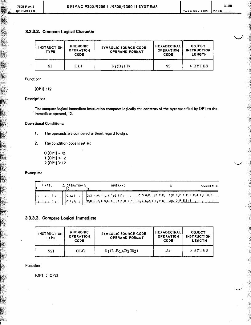
7508 Rev. 3 UP.NUMBER
UNIVAC 9200/9200 11/9300/9300 II SYSTEMS 3-28 PAGE REVISION PAGE
3.3.3.2. Compare Logical Character
INSTRUCTION MNEMONIC SYMBOLIC SOURCE CODE HEXADECIMAL OBJECT
TYPE OPERATION OPERAND FORMAT OPERATION INSTRUCTION CODE CODE LENGTH
SI CLI °1(B1),12 95 4 BYTES
Function:
(OP1) : 12
Description:
The compare logical immediate instruction compares logically the contents of the byte specified by OP1 to the immediate operand, 12.
Operational Conditions:
1. The operands are compared without regard to sign.
2. The condition code is set as:
Examples:
O(OP1)=12 1 (OP1) < 12 2 (OP1) > 12
LABEL 6 OPERATiON 6 OPERAND 6 COMMENTS 1 10 16
I C I L 1L-..L-r-l.lh~., XI' 1 0 19 1' I ,-~~~MIP,Llk"!.tE~l!',E,C,I,FIIIC,A,T,11 0 ,1'1, I
I C I L.J.lL CM,R,AIB,L,E,.~AI I R, E, LL~L!l!.-L"'LI::.L01E~, E,5 15, I , I I I I I
3.3.3.3. Compare Logical Immediate
INSTRUCTION MNEMONIC SYMBOLIC SOURCE CODE HEXADECIMAL OBJECT
TYPE OPERATION OPERAND FORMAT OPERATION INSTRUCTION CODE CODE LENGTH
SS1 CLC 01 (L ,B1), 02(B2) 05 6 BYTES
Function:
(OP1) : (OP2)

7508 Rev. 3 UNIVAC 9200/9200 11/9300/9300 II SYSTEMS UP·NUMBER PA GE RE VISION PAGE
Description:
The compare logical character instruction performs an absolute binary comparison of the contents of the address specified by OP1 of the contents of the address specified by OP1 to the contents of the address specified by OP2. The number of bytes to be compared is determined by the length specification in the first operand; the maximum is 256 bytes.
Operational Conditions:
1. Execution of the instruction is terminated and the condition code is changed after the first inequality is found.
2. The condition code is set as:
Examples:
1
o (OP1) = (OP2) 1 (OP1) < (OP2) 2 (OP1) > (OP2)
LABEL /'; OPERATION /'; 10 16
OPERAND /'; COMMENTS
1 CI L C 1,( 1 0 11 5 ) 712 ( 8 ) ICOMPLIETE SIP E ~L1!,S&T-,1 ~L"'-'-L~~L-'-~L
I CI L C 1,( 1 51) 7 2 ( 18 ) II ~L~~B"'~~_LLL~.L LLL-'----'--.J._L---'--'.~..1~ ,
L CLLCt ~QU A D-.t! [1 01 T1R A P ~~~"IlJ..L.J.h~Q,D LR,E.l~ 1~..J. .L L L ...l.C .. .l l __ L 1 L_1
I ICll Co aU,A,D IT RAP I -'-, I II ,M,P,Llllc,1 , L.n.LL~G1TLHJ,A-,--N-,-.QL~J>LR.L~1~L.J.
1 I I I _L .1 1 I I I I , I I
3.3.3.4. Compare Packed Decimal
INSTRUCTION MNEMONIC SYMBOLIC SOURCE CODE HEXADECIMAL OBJECT
TYPE OPERATION OPERAND FORMAT OPERATION INSTRUCTION CODE CODE LENGTH
SS2 CP Dl(Ll,Bl),D2(L2,B2) F9 6 BYTES
Function:
(OP1) : (OP2)
Description:
The compare packed decimal instruction algebraically compares the contents of the bytes specified by OP1 to the bytes specified by OP2; the maximum number of bytes is 16. Both OP1 and OP2 should contain packed decimal fields.
I
3-29

1508 Rev. 3 UNIVAC 9200/9200 11/9300/9300 II SYSTEMS UP.NUMBER PAGE REVISION PAGE
Operational Conditions:
1. The operands are processed from right to left.
2. If OP1 is larger than OP2. the remaining digits of OP1 are compared to zero. If OP2 is larger than OP1. the remaining digits of OP2 are ignored.
3. A sign is assumed in the four rightmost bits of the least significant byte of both operands and is considered in the comparison.
4. The condition code is set as:
Examples:
o (OP1) = (OP2) 1 (OP1) < (OP2) 2 (OP1) > (OP2)
LABEL /:; OPERATION /:; I 10 16
OPERAND /:; COMMENTS
I CIP 6,( I 3 19 ,I ~hL.L-llli.J...L-'--L. IC,O,M,P,LIE,T,E, ~P,E,C,I ,FII ,C,A,T,I 10,14, , 1--.l~1...L i Cl~ "----'- . . 6..J-L' L9,1.1 ,,~8hL'"~.J-, _,-1. 1 .L.L_,_U . .JoI.L~L,.J.lE.,pL..!L~.l~G ,T ,H 1.l.L. L-.L-Ll_-.L--L-"---,-.l.LLL
I I<:IP P R,O,V,OI( ,1,3,1 IS,D,S,( 113,1 -LLlBtf:,LliIlIII,V,!;, IAIDIDIRIElslsl , , , I , , , , I , , L
I C1P P R OVOI,,5,D,S, I , , , , I , ,--LL.J.L.M, P,L,'I C,I ,T, ,AID, ~!hl;~..L~ ILl E1NIGI TIHI ,
3.3.3.5. Test Under Mask
INSTRUCTION MNEMONIC SYMBOLIC SOURCE CODE HEXADECIMAL OBJECT
TYPE OPERATION OPERAND FORMAT OPERATION INSTRUCTION CODE CODE LENGTH
SI TM 01(Bl),12 91 4 BYTES
Function:
test (OP1) : 12
Description:
The test under mask instruction tests the bits in the byte specified by OP1. using 12 as a mask for the test. Bit positions not to be tested are indicated by 0 bits in the mask; 1 bits indicate bit positions to be tested.
Operational Conditions:
1. The condition code is set as:
o No match 1 Partial match 2 Not used 3 Full match

7508 Rev. 3 UP.NUMBER
UNIVAC 9200/9200 11/9300/9300 II SYSTEMS 3-31 PAGE REVISION PAGE
Examples:
LABEL D. OPERA TION D. OPERAND D. COMMENTS 1 10 16
I TIM 8 0.( 1 41 \ X· Fll • I IC 0 M P LIE T E SIPECIFII CATllo.N
I TIM PH E A AI X· F lU-'---..L.L-L...L I I I IRIEILIAITIIIVIEI IAIDI DtfuLli-SI I I I I I I
3.3.4. Data Manipulation Instructions
The data manipulation instructions edit, translate, or change formats of data stored in main storage. The instructions include:
Mnemonic Function Format
ED Edit SS1 PACK Pack SS2 TR Translate SS1 UNPK Unpack SS2
Of the data manipulation instructions, only the edit instruction sets the condition code. Operands are processed from left to right in the translate and edit instructions and from right to left in the pack and unpack instructions.
The instructions are explained separately in the text and are accompanied by notes on their limitations and operands.
3.3.4.1. Edit
INSTRUCTION MNEMONIC SYMBOLIC SOURCE CODE HEXADECIMAL OBJECT
TYPE OPERATION OPERAND FORMAT OPERATION INSTRUCTION CODE CODE LENGTH
SSl ED Dl(L,Bl),D2(B2) DE 6 BYTES
Function:
(OP2) -+ OP1
Description:
Execution of the edit instruction transfers data from the bytes specified by OP2 to the bytes specified by OP1, changing the data format from packed decimal to unpacked decimal, inserting zone bits and editing symbols, and suppressing leading zeros. This editing process is controlled by the editing mask in OP1, which is overlaid by execution of the instruction. OP2 should be a packed decimal field and OP1 should contain the editing mask.

150s Rev. 3 UP.NUMBER
UNIVAC 9200/9200 11/9300/9300 II SYSTEMS 3-32 PAGE REVISION PAGE
Operational Conditions:
1. The following pertains to the 9200 system optional software version of this instruction; see also card utility programs programmer reference manual, UP-4120.
1
• The software edit function is provided by a fixed, closed subroutine in relocatable object code. It requires approximately 375 bytes of main storage and must be linked to the problem program. To make this linking possible, the following source code must be inserted in the program:
LABEL b. OPERATION b. OPERAND b. 10 16
I EI X T R N ED I T I I I I I I I I I I I I I I I I I I I I I L I I I I I I I I I I I I I I I I I I I I I I I I I I I I I I I j
• The source code necessary to accomplish the instruction is:
I : : : : : : : II:::: L: : II::::;:~:::::~: : : : : : : : : : : : : : : : : : : : : : : :
2.
• Other than the above, the software edit instruction is identical in operation to the hardware version.
The operands are processed from left to right.
3. The contents of OP1, after execution of the instruction, are dependent upon:
Fill character Digit select byte (DSB) Significant start byte (SSB) Field separator byte (FSB) Editing symbols Sign of OP2
a. Fill character
The leftmost byte of OP1 contains the fill character, which can be any alphanumeric or special character. It is used to replace bytes in the OP1 editing mask. The first byte always remains as the fi II character.
The fill character is substituted for:
• Leading zeros - any zero in OP2 not preceded by a significant nonzero digit.
• Leading editing symbols - any byte containing one of the available characters specified for editing in the OP1 mask not preceded by a significant digit.
• Field separator byte - a special byte that acts as a separator in multiple field editing.
• Rightmost bytes of OP1 when the sign of OP2 is positive.
The most commonly used fill characters are the asterisk and the blank.

7508 Rev. 3 UP.NUMBER
2
3
4
5
6
7
8
9
b.
UNIVAC 9200/9200 11/9300/9300 II SYSTEMS 3-33 PAGE REVISION PAGE
Digit select byte (DSB)
The digit select byte, a hexadecimal 20, is replaced by digits from OP2 or by the fill character. The DSB is replaced by a digit from OP2 if that digit is significant or was preceded by a significant digit. The fill character replaces the DSB in all other situations.
c. Significant start byte (SSB)
By using a significant start byte, hexadecimal 21, in OP1, the presence of a significant digit in OP2 is simulated. The suppression of leading zeros and fill characters ceases with the byte immediately following the SSB.
d. Field separator byte (FSB)
The field separator byte, a hexadecimal 22, is used in the OP1 mask to separate fields in multiple·field editing. The FSB always is replaced by the fill character, and all leading zeros or editing symbols following the FSB also are replaced by the fill character. This procedure continues until a significant digit is processed or an SSB is specified in OP1 just as if this were the beginning of a new editing instruction.
e. Editing symbols
f.
Any alphanumeric or special character may be specified as an editing symbol in OP1. These symbols never are replaced by a digit from OP2, but are replaced by the fill character before a significant digit has been processed.
Sign of OP2
If any byte of OP2 contains a 4·bit digit with a value greater than eleven (X'OB'), it is recognized as a sign. If the sign of OP2 is positive, any editing symbols in the mask at the end of OP1, or between the last DSB and an FSB, are replaced by the fill character. If the sign of OP2 is negative, these editing symbols remain in OP1.
4. Zone bits are inserted in OP1 when digit bits from OP2 overlay the editing mask. The bits inserted are 1111 in the EBCDIC mode, and 0101 in the ASCII mode.
5. An example of the use of the edit instruction is:
LABEL 1; OPERATION 1; OPERAND 1; 1 10 16
° PO", I DIC XL 6 ' 01' I J J 1 . L
° P T U I OIC XL4' 01' I I I I I I I I I I I I I I I I I
E OMK I olC X' 4021020 6 BI20 2 1 2104B20120 C 3 019 ' I
I :1 I i 1 III 1 -1 I ill
A LIP AI I MIV C ° po", , IE OMK I I I I I I
I EIO ° po'" , 10 P T U I I I I I I I I I I I I I I I I I I I I L I P,u T P RIII"'ITI'loIPlol"'l I I I I I I I I I I I I I I I I I I I I
I : I I I I I I I I I I I I I I I I I I I I I I I I I I I BIC 1 5 , AiLJ P A I I I I 1 I I

". c
;
7508 Rev. 3 UP.NUMBER
UNIVAC 9200/9200 11/9300/9300 II SYSTEMS 3-34 PAGE REVISION PAGE
Line 1. A work area, OPON, is defined and binary O's are used to fill it. It is the same length as the editing mask.
Line 2. A work area, OPTU, is defined and filled with binary O's. The packed number to be edited is moved here.
Line 3. The editing mask, EDMK, is defined.
Line 4. Processing takes place; the number is generated.
Line 5. The editing mask is moved to preserve it.
Line 6. If OPTU contains a value representing -106071 and the desired output format is xx,xxx.xx if positive and xx,xxx.xxCR if negative, the operation of the edit instruction is:
a.
b.
c.
d.
e.
f.
OP2
OPl
a b C d e g h k k
OPl
The fill character remains; this first byte never is replaced.
The corresponding digit in OP2 is a leading zero; the fill character replaces this DSB.
The corresponding digit in OP2 is significant; it replaces the DSB.
This editing symbol, a comma, remains in OP1 because it was preceded by a significant digit.
This DSB is replaced by the digit from OP2 because it was preceded by a significant digit.
This SSB is replaced by the significant digit from OP2. It is placed in the mask to ensure that the next di$lits are placed in OP1 even if they are leading zeros.
g. This DSB is replaced because it is preceded by a significant digit and because it is preceded by an SSB; either is sufficient.
h. This editing symbol, a period or decimal point, remains in OP1 because it was preceded by a, __ ,/ significant digit or an SSB.

7508 Rev. 3 UP-NUMBER
UNIVAC 9200/9200 11/9300/9300 II SYSTEMS PAGE REVISION PAGE
i. This DSB is replaced by the significant digit from OP2.
j. This DSB is replaced by the significant digit from OP2.
k. These editing symbols, C and R (any number of the available characters could have been specified), remain in OP1 because the sign of OP2, a hexadecimal 0, was negative.
The result of the operation stored in OP1 is 1 ,060.71 CR.
Line 7.
Line 8.
Line 9.
line 5.
Line 6.
The result of the editing process is then moved before printing.
More processing occurs and another number is derived for editing.
An unconditional branch back to the editing path is specified.
The mask is moved again.
If OPTU contains a value representing .71, and the output format is the same, the operation of the instruction is:
OP2
OP!
OP!
a. The fill character replaces the first six bytes of OP1 because no significant digit was processed in OP2.
b. The SSB is replaced by the fill character, but the next byte is replaced by the corresponding digit from OP2.
c. This DSB is replaced from the OP2 digits because it was preceded by an SSB.
d. This editing symbol remains because of the previous SSB.
e. This DSB is replaced by the significant digit from OP2.
3-35

7508 Rev. 3 UP.NUMBER
UNIVAC 9200/9200 11/9300/9300 II SYSTEMS PAGE REVISION PAGE
f. This OSB is replaced by the significant digit from OP2.
g. These editing symbols are replaced by the fill character because the sign of OP2, a hexadecimal F, is positive.
The result of the operation sorted in OP1 is 0.71.
6. The edit instruction sets the condition code as:
o The portion of OP2 following the last FSB is zero, or the last byte of OP1 is an FSB.
The portion of OP2 following the last FSB is not zero and is placed in OP1.
2 The portion of OP2 following the last FSB is not zero and is replaced by the fill character in OP1.
The condition code settings are useful in multiple·field editing, but do not reflect the contents of any part of OP2 that precedes the last FSB in the editing mask.
Examples:
LABEL /:,. OPERATION /:,. OPERAND /:,. COMMENTS I 10 16
I EID 1 6,( 2 11 1 4 ) .18 3 ( 9 ) I Clo,MIPILIE,~1 I S, PI EIC II I FLI LC-,Ai!L!, 01 H I , L . ..L~L
I IEID, 1,6,( 114') ,8 31( 9,) I I M plL I E 0 ILl EIHIGITIHI I _--.L_Ll_l..........l.._...L_L~ ..L-1 __ 1_
I EID o P 0 H,( 12 hL.tu.FILIDI21 I I I , R~J-t! .L~~~' 0 1 RI E,S l,~,L~-'-~-1 -1-,1
I IElo. IO,P,O,H .LfLI..U!, 2 , I , I , , I , ,h~J'J.I'·JJ_.J..!;.LLJl.J.b.&Hl!'iTJ.H_,-"A,~DLl A,i?l.o..lR , ~,S l~ ,_
3.3.4.2. Pack
INSTRUCTION MNEMONIC SYMBOLIC SOURCE CODE HEXADECIMAL OBJECT
TYPE OPERATION OPERAND FORMAT OPERATION INSTRUCTION CODE CODE LENGTH
SS2 PACK 01 (L1 ,B1),D2(L2,B2) F2 6 BYTES
Function:
(OP2) -+ OP1
Oescri pti on:
Execution of the pack instruction transfers the contents of the bytes specified by OP2 to the bytes specified by OP1, altering the data format from unpacked decimal to packed decimal.
Operational conditions:
1. Operands are processed from right to left, as:
OP2 (unpacked decimal) OP1 (packed decimal)
3-36
''-../'

7508 Rev. 3 UP.NUMBER
UNIVAC 9200/9200 11/9300/9300 II SYSTEMS
where:
Z = zone bits D = digit bits S = sign bits
PAGE REVISION
Note that the first byte sign and digit positions are reversed by execution of the instruction.
PAGE
2. If OP1 is larger than OP2, the remaining digits of OP1 are zero filled; if OP2 is larger than OP1, the excess digits of OP2 are ignored.
3. The maximum length of operands is 16 bytes.
4. Execution of the instruction does not change the condition code setting.
Examples:
LABEL /', OPERATION /', OPERAND /', COMMENTS I 10 16
I PIA C K 0 ( 3 , 81) 1 9 ( '1 5 , 9 ) I CO MjP L E T~.~iP_,~~~,F~.LC1ALTil.OLN"_i _. I plACK 0,( 8,) I 1 9,( 19, ) I I I ; 11."1LP~&L~ lL.J:..l!:l"GJ.:!Jt:tL Lt Ll...L.L..L ._ ... L. 1 j
I Ipl ,e,K E,M, ,I ,31) J, B,LII 5,) 1 R E UA T I V E; -,~J~.d2 . .J'!l.!;j~lSJ.. j 1. .L. .•. ...I " L 1 , I Ipl ,e,K E,MlI JI B,L 1 --,-,--,--I , ,I,MIPILI~iTl . ......l.,~E,NLG1I.LHj L!<lI-l.L!L. cl<., P,PLR,!, j~l~'
3.3.4.3. Translate
INSTRUCTION MNEMONIC SYMBOLIC SOURCE CODE HEXADECIMAL OBJECT
TYPE OPERATION OPERAND FORMAT OPERATION INSTRUCTION CODE CODE LENGTH
SSl TR Dl(L,Bl),D2(B2) DC 6 BYTES
Function:
Translate (OP1) using (OP2) -+ OP1
Descri pti on:
Execution of the translate instruction replaces the bytes of OP1 with the contents of the translation table at OP2. The binary value of each OP1 byte is used as the relative address of its replacement in the translation table.
Operational conditions:
1. Translation of OP1 occurs one byte at a time in a left·to·right sequence.
2. The capacity of the translate table is 256 characters.
3. The length specified in OP1 determines the number of bytes translated.
3-37
--

7508 Rev. 3
UP.NUMBER
;,., .. -.
UNIVAC 9200/9200 11/9300/9300 II SYSTEMS PAGE REVISION PAGE
4. OP2 is not changed by execution of the instruction.
5. Execution of the instruction does not change the condition code setting.
6. The instruction operates as:
1
The user has a message in his program that is in his own code, which, for this example, consists of a simple substitution of a number for a letter, 1 for A, 2 for B, ... , 26 for Z, and zero for blank. If the message is to be printed, the characters must be in EBCDIC code.
The programmer sets up a table and stores it in main storage; in this case, it is stored at location 6000 and labeled TBLE. The table is 27 bytes long, but could be a maximum of 256 bytes. TBLE contains the hexadecimal values:
TBLE (location 6000) 40
TBLE + 1 C1
TBLE + 2 C2
TBLE + 26 E9
In other words, TBLE contains the equivalent of the EBCDIC code for the alphabet.
The message in the program that must be translated is, in hexadecimal:
00,05,13,13,01,07,05,00,09,13,00,14,12,01,
OE, 13,OC, 01, 14,05,04
The message is labeled NOTE and is 21 bytes long.
The instruction used to translate NOTE is:
LABEL 6. OPERATION 6. OPERAND 6. 10 16 .
I TIR N o T E ( 12 1 ) i, TIB L E j I I 1
1 i I I I I I 1 I I I I I I I I I I I I I I I I
In the operation, the binary value of each byte is used to address relatively its replacement in the tra'1slation table.
The value of the first byte of NOTE is 13 (because 00 in hexadecimal equals 13 in decimal); it is replaced by the thirteenth byte of TBLE (location 6000 + 13). TBLE + 13 contains the value 1101
3-38
0100, an EBCDIC M. That value replaces the first byte of NOTE. ..J
.,;;
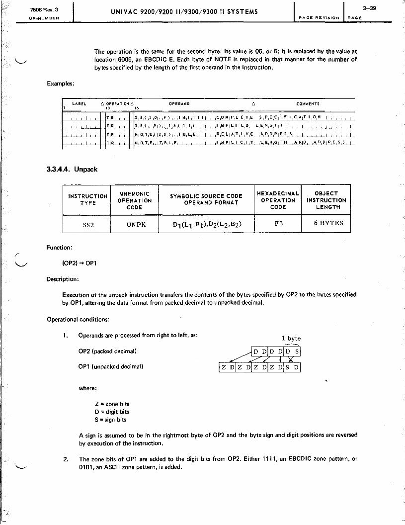
7508 Rev. 3
UP.NUMBER
UNIVAC 9200/9200 11/9300/9300 II SYSTEMS PAGE REVISION PAGE
The operation is the same for the second byte. Its value is 05, or 5; it is replaced by the value at location 6005, an EBCDIC E. Each byte of NOTE is replaced in that manner for the number of bytes specified by the length of the first operand in the instruction.
Examples:
LABEL D. OPERATION D. OPERAND D. COMMENTS 1 10 16
1 TIR 3 5 ( 2 01, 9 ) ~~)I , Ic,o,M~~U--'-"~BI,F,I,C,AIT,I,O,N, I , , , I~ I T~--,---,-- 3--,-5~"'-'-.t?1 L'-'-'. .. L~ .. LU!.J...!.J--'-_L.L .. L_.c!.~,~~ LE..cP..Ll L~~....L L. 1... .. L J .. ..L .. L....L~-'--'-Ll ..
I TIR N O,TIE I( 12,0,)" ,TIB,L,E, , I , ,R,E'~~LV,EI ,A,D,D,RIE,S,S, , I , , , , I , , I , I
I TIR N o T E . IT B L E , , I~~TI I L, E,N,GIT,H~l..~~-L. ,AIDIDI RIEl 5, S, I
3.3.4.4. Unpack
INSTRUCTION MNEMONIC SYMBOLIC SOURCE CODE HEXADECIMAL OBJECT OPERATION INSTRUCTION TYPE OPERATION OPERAND FORMAT
CODE CODE LENGTH
SS2 UNPK Dl(Ll,Bl),D2(L2,B2) F3 6 BYTES
Function:
(OP2) ~ OP1
Descri pti on:
Execution of the unpack instruction transfers the contents of the bytes specified by OP2 to the bytes specified by OP1, altering the data format from packed decimal to unpacked decimal.
Operational conditions:
1.
2.
Operands are processed from right to left, as:
OP2 (packed decimal)
OP1 (unpacked decimal)
where:
Z = zone bits D = digit bits S = sign bits
1 byte
A sign is assumed to be in the rightmost byte of OP2 and the byte sign and digit positions are reversed by execution of the instruction.
The zone bits of OP1 are added to the digit bits from OP2. Either 1111, an EBCDIC zone pattern, or 0101, an ASCII zone pattern, is added.
3-39

7508 Rev. 3 UP.NUMBER
UNIVAC 9200/9200 11/9300/9300 II SYSTEMS PAGE REVISION PAGE
3. If OP1 is larger than OP2, the remaining bits of OP1 are filled with the unpacked zero character (X'FO' EBeD Ie). If OP2 is larger than OP1, the excesS bits of OP2 are ignored.
4. Maximum length of operands is 16 bytes.
5. Execution of the instruction does not change the condition code setting.
Examples:
LABEL b. OPERATION b. OPERAND b. COMMENTS 1 10 16
1 UIN P K 3 8 ( 1 01. 1 5 ) • 1 ~~~~.LI2J-"-~,M,P,L~.L1Sl~<:..cI-,!~A~~~LLLLLLL I U N P K 3 ~J..L.!ijL.!~l.Jl!lJ-'-L~!21lLL1._Ll!,M, P,L~l!'-,.DL tS!lNL~-,H~ __ LLl ~ ~ LL.1 LLl 1-1-1..
1 UIN P K D F ~ .J..~Io\L...L,L[)U_l~L.,_~ _~~.L:TL' LV.L~Lj~D.J Dj ll2' ~Sl S.L , LL LL.L1 , 1 J 1 J
1 UIN P K DFLD,INUMFLID 1 --,---,-.J!.-,-M, P ,L,I I C "-,--,-T-'-_ll:.l~i'lLGt!,H.L LA, N.J D Ll ~lD.l~ lR ,E 1 S J S
1. 1
1 1 I I 1 I I I I I 1
3.3.5. Data Transfer Instructions
The data transfer instructions move data between storage locations and registers, other storage locations, or immediate operands. The data transfer instructions include:
Mnemonic Function Format
LH Load half word RX MVe Move characters SS1 MVI Move immediate data SI MVN Move numerics SS1 MVO Move with offset SS2 STH Store half word RX
The formats of the data transfer instructions vary with the function of the instruction. The instructions do not change the condition code setting, and operands are processed from left to right on all instructions except the move with offset.
The instructions are explained separately in the text and are accompanied by notes on their limitations and operations.
3.3.5.1. Load Half Word
INSTRUCTION MNEMONIC SYMBOLIC SOURCE CODE HEXADECIMAL OBJECT
TYPE OPERATION OPERAND FORMAT OPERATION INSTRUCTION CODE CODE LENGTH
RX LH Rl,D2(,B2) 48 4 BYTES
Function:
(OP2) -+ R1
3-40
'-../

7508 Rev. 3 UP.NUMBER
UNIVAC 9200/9200 11/9300/9300 II SYST EMS PAGE REVISION PAGE
Descri ption:
The load half·word instruction transfers the contents of the half word specified by OP2 to the register specified by R 1.
Operational conditions:
1. The OP2 address should be defined at a half·word boundary.
2. Execution of the instruction does not change the condition code setting.
Examples:
LABEL f::, OPERATION f::, OPERAND f::, COMMENTS I 10 16
1 ~JJ:i~L-'- ~!~1115,)1 , L-L~.L~C,O,M,PLLIE,T,E, , SJMl C-LL1DL£l-~lJn.O.LIoI~_ 1..._1 L1
I LJ!!LLL ._ 8.lL.l.!,~S..rr-LG~LL.L L1 __ L.l..J......L--'~l~J:..lJ..LT1I_,""-~L-LA1D~DIR,E,SJ.S_L . ...L.L 1.:1..1 1..1 1 1..j 1
3.3.5.2. Move Characters
INSTRUCTION MNEMONIC SYMBOLIC SOURCE CODE HEXADECIMAL OBJECT
TYPE OPERATION OPERAND FORMAT OPERATION INSTRUCTION CODE CODE LENGTH
SSI MVC Dl(L,Bl),D2(B2) D2 6 BYTES
Function:
(OP2) ~ OPl
Descri pti on :
Execution of the move characters instruction transfers data from the bytes of main storage specified by OP2 to the address specified by OP1. The number of bytes transferred is determined by the length specification in OP1. The maximum number of bytes that can be moved is 256.
Operational conditions:
1. Characters are moved unaltered and OP2 is unaltered by the instruction.
2. Execution of the instruction does not change the condition code setting.
Examples:
1--'---'----'---'_L-LI--'---H-"'ML'VCLC"'--L-4---¥2~..tl.t..!j9..L...t..9~J__'_!.LLJ . .cllLLLL..1 __ 1C O,MJ'..Jb.l~.:LL..1Hf>L~~..LGflhC.c& T,I IO,N, , ,_LLL..
p~-'-'-_LI __ L~+ __ ~~----'-- T,AIGl,"IJI,4) l!lSD" II -"-_L -' L..1. , . .lL.M.cP---,-LJ.IlL.~ LLJ:ll'lc§.LH.U--'----'---'----'....L..L __ -'---'----".J .. L1..
~~__ M~ £....1-LS.L"-'--RlJ..L8"OJ._'-'_Lc:LA".~LL.l.---'-_-'---.L .. ~E.J-~Il'-2·.1.!.L-,~D-,~~E~1~-'--L--,----,....L...L __ LL..I. L.L ._-'-
I--'--'----'---'_L-LI-'---H"'MLV-'--C F I S Y RI. ~-,--------,-Ll.._L--'- __ L.L Lll~.!' __ .L lj'<=L.!.Ll~lE-,--~EL'T2L1A--,-~DU~_~..l~lR..!1 Sl~L
J.. L J J J I L
3-41

7508 Rev. 3 UNIVAC 9200/9200 11/9300/9300 II SYSTEMS 3-42 UP.NUMISER PAGE REVISION PAGE
3.3.5.3. Move Immediate Data
INSTRUCTION MNEMONIC SYMBOLIC SOURCE CODE HEXADECIMAL OBJECT
TYPE OPERATION OPERAND FORMAT OPERATION INSTRUCTION CODE CODE LENGTH
SI MVI °1(B1),12 92 4 BYTES
Function:
12-+ OP1
Description:
The move immediate data instruction transfers the immediate data, 12, to the byte specified by the OP1 address.
Operational conditions:
Execution of the instruction does not change the condition code setting.
Examples:
LABEL /:, OPERATION /:, OPERAND /:, COMMENTS 1 10 16
I MIV I 1 4 2,(~,) I. ,X,' i8,A,', , I , , , , IC,O,M,P,LIE,T,E, ,5IP,E,C,I,F1!-1~~}J.~L~
I MIV I 5 Y 5 ALI P • X' 81~_,_....Ll. , , , , IR,E-,-~A,TII V,E, ,AID,D,R, E,51 5, , , I ,
I I I I I I I-------L...L_L .! I , , , Ll--"-------.l.-LJ_..L.L
3.3.5.4. Move Numerics
INSTRUCTION MNEMONIC SYMBOLIC SOURCE CODE HEXADECIMAL OBJECT OPERATION INSTRUCTION TYPE OPERATION OPERAND FORMAT
CODE CODE LENGTH
SS1 MVN 0 1 (L,B1),02(B2) 01 6 BYTES
Function:
(OP2) -+OP1
Descri pti on :
The move numeric instruction transfers the numeric bits from the bytes of data specified by OP2 to the numeric bits of the bytes specified by OP1. The number of bytes affected by the instruction is dependent on the length specification of OP1 ; the maximum is 256.
J~., ~7

7508 Rev. 3 UNIVAC 9200/9200 11/9300/9300 II SYSTEMS UP.NUMBER PAGE REVISION PAGE
Operational conditions:
1. The zone bits of the bytes in OP1 are unaffected by the instruction.
2. Execution of the instruction does not change the condition code setting.
3. The instruction functions as:
OP1 (before execution)
OP2
OP1 (after execution)
1 byte ~
After execution of the instruction, the zone bits of OP1 are unaltered and the digit bits are overlaid by the digit bits from OP2.
Examples:
LABEL D. OPERA nON D. OPERAND 10 16
~~'--L-,ILL-'--lI--f"M"-IV,-,-,,N"--L+4fuLL9 J..... ,1 10 ,) ,. I 1 ,1 1 ( d I 2,) ,
1 MIV N 8 ( . 1 ,0 I) I' ,1 ,1 ,<-l!J.!.LL'---_Ll
I J I I
I I j I
COMMENTS
IC,O,M,P,Ll~~1f'J..E1C:LI1l!LClhlJJ9..LN.l_ 1......1 LI 1
1I.JoIJ'....L!,.c!l!..l!l.L..lL,EIN.cGlT,HLLL..l.. __ L._L . ..L~.L_L L1 1 I ..
~---L-'--L-'ILL-'--l-FMlIV'-'-'-'NL-L+40,C,T~..L~t:lL.l.. , , , 1 ,~....L..1RLE.l..LL~I_l..~LEL..l..~__' D,R1El~lSLlL 1 J...._,-- j , 1 1 .1 1
1 M1V..l..~L..L O~~. LZl~l~L_L.l.....L--'-L_LLL.L" . ..1 LI_1M1Pl.L11 .. LC) .. , Tl_1L~E, N,Gj T, HJ lA,N. 0, l.A, D, D,R"Ej S,S I
I I I I I , I
3.3.5.5. Move With Offset
INSTRUCTION MNEMONIC SYMBOLIC SOURCE CODE HEXADECIMAL OBJECT
TYPE OPERATION OPERAND FORMAT OPERATION INSTRUCTION CODE CODE LENGTH
SS2 MVO Dl (Ll,Bl),D2(L2 ,B2) Fl 6 BYTES
Function:
(OP2) -+OP1
Descri pti on :
Execution of the move with offset instruction transfers data from the bytes specified by OP2 to the bytes specified by OP1. moving the data four bits to the left as it is processed.
Operational conditions:
1. The operands are processed from right to left.
2. The first four bits of OP1. the least significant or rightmost bits, always remain unchanged.
3-43

7508 Rev. 3 UP-NUMI!IER
UNIVAC 9200/9200 11/9300/9300 II SYSTEMS PAGE REVISION P",GE
3. If OPl is larger than OP2, the remaining leftmost positions of OPl are zero filled. OPl must be at least one byte larger than OP2 to avoid truncation of the data on the left. If OP2 is larger than OP1, however, the excess leftmost positions of OP2 are ignored.
4. The maximum length of operands is 16 bytes.
5. Execution of the instruction does not change the condition code setting.
6. The instruction functions as:
LABEL !::. OPERATION!::. OPERAND 1 10 16
I MIV 0 DIA T A 0IN1E1( 3 I) I, DATA1TWO( 31)
I I I I I I I
results in:
OP2 los t -------'
r-~~~~ __ ~~ __ ~unchanged
OPl
results in:
OP2
inserted
OP1
results in:
OP2
OPl
where:
01, ... ,06 = digits occupying four bits of the byte. x = the original contents of these positions. 0= zero fill of the MVO instruction.
unchanged
unchanged
1 byte
!::.
i li.i..liJ
1 I
I I

7508 Rev .• 3 UP-NUMBER
UNIVAC 9200/9200 11/9300/9300 II SYSTEMS 3-45 PAGE REVISION PAGE
Examples:
LABEL t. OPERATION t. OPERAND t. COMMENTS I 10 16
I lollY 0 I I d I 61. ,I, I') ,. 1210 ,L..LlJ2l.Lll1.L1LLLJho,t.Il!'.iL, E, T ,E-.l_~"P1E,ql.LF,I . .LC~AL~ I ,O,N, 1 , , I lIy,o, I ,,1 I 11,) 2 OluLt.'-1.J.LHl.L..LL..L..l..L~l!-~~..Jb!,N-,G,TlI'It_ui..LL.L j , I , , ! j
I lollY ° MOOG(116) llhN,T,H, I , , , ,_J.---' . .LRL~A..l.!J..~.-"-AjI:lL°.L~EjS~,.l 1.1. j , , i j , I lollY ° 101.0 ° G IS Y,N,T,HI , , , , I , ' .... LL LL.L'-'-M'~-'-ll_.t'!"LLL--,-E-,.N,~ T,H, ,A,tollo, .,A,D,DIR,E,S,S,
3.3.5.6. Store Half Word
INSTRUCTION MNEMONIC SYMBOLIC SOURCE CODE HEXADECIMAL OBJECT
TYPE OPERATION OPERAND FORMAT OPERATION INSTRUCTION CODE CODE LENGTH
RX STH Rl,D2(,B2) 40 4 BYTES
Function:
(R1)-+OP2
Descri ption:
The store half-word instruction transfers the contents of the register specified by R 1 to the half word in main storage specified by the OP2 address.
Operational conditions:
1. The OP2 address should be defined at a half-word boundary.
2. Execution of the instruction does not change the condition code setting.
Examples:
I SIT H 1 5 • o (J. 9 ) , C, 0 Mj P LET E I S P E CJ I FI CAITION
j S jT H 1 5 USIE FUL I R, E LI A T I V E I A D,D,RI E,S,S I I j I I I
3.3.6. Display Instruction
The halt and proceed instruction is a display instruction; its execution stops the processor and displays a selected series of digits in the halt/display indicators of the console.
Mnemonic Function Format
HPR Halt and proceed SI
-;2

7508 Rev. 3 UNIVAC 9200/9200 11/9300/9300 II SYSTEMS UP.NUMBER PAGE REVISION PAGE
3.3.6.1. Halt and Proceed
INSTRUCTION MNEMONIC SYMBOLIC SOURCE CODE HEXADECIMAL OBJECT
TYPE OPERATION OPERAND FORMAT OPERATION INSTRUCTION CODE CODE LENGTH
SI HPR Dl(Bl),I2 A9 4 BYTES
Function:
display OP1
Description:
Execution of the halt and proceed instruction stops the processor and causes a display in the halt/display indicator on the console. If the most significant bit of OP1 is 0, the display is the 16 bits of OP1, as specified in the instruction. If the most significant bit of OP1 is 1, the display consists of the contents of the register specified by the leftmost 4 bits of OP1, plus the rightmost twelve bits of OP1.
Operational conditions:
1. 12 of the SI format need not be specified with this instruction.
2. The next instruction in sequence is executed by pressing START.
3. Execution of the instruction does not change the condition code setting.
Examples:
LABEL 6. OPERATION 6. OPERAND 6. 1 10 16
I HIP R X • 3 F FI F' 10 I SPLIAYS 31F F F I I
I HIP R 2 4 ( 8 ) 1 I I I I 10 II IS IP ILl AIY I SI I AIDIDIRI E1SIS I I I I I I
3.3.7. Input/Output Instructions
T he input/output instructions are a pair of instructions that test the status of an input/output device or initiate an input/output function. The instructions are:
Mnemonic
TIO XIOF
Function
Test input/output status Execute input/output function
Format
SI SI
The instructions are explained separately in the text and are accompanied by notes on their limitations and operations.

7508 Rev. 3 UNIVAC 9200/9200 11/9300/9300 II SYSTEMS UP.NUMBER PAGE REVISION PAGE
3.3.7.1. Test Input/Output Status
INSTRUCTION MNEMONIC SYMBOLIC SOURCE CODE HEXADECIMAL OBJECT
TYPE OPERATION OPERAND FORMAT OPERATION INSTRUCTION CODE CODE LENGTH
SI TIO D1 (B1),12 AS 4 BYTES
Function:
status -+ OP1
Descri ption :
Execution of the test input/output status instruction tests the status of the device specified by 12 and sets the condition code; the status of the device tested is stored in the byte specified by the OP1 address.
Operational conditions:
1. The instruction clears the device status for the device tested if the device is not busy. If the device is busy, the status is not reset.
2. The interrupt request is part of the device status and is cleared by the instruction.
3. The condition code is set as:
Examples:
1
o Device is available. 1 Valid status. 2 Busy. 3 Rejected.
LABEL IJ. OPERA nOM IJ. 10 16
OPERAMD IJ. COMMEM'
I Til 0 2 0,( 1 51) X' o 15 '-_LLLlf.tQLM-,-~L~l~~l--L~' E ,C ~!.L~~ A, T II 10 , N...L
I rI1L&LL _ E,V,EL'iu Lb·_~_LLLL-1_R~~.J,.~LIlL-""l!'-,~LD,D,R~.LUS--,- L L .. LJ --'--- i
3.3.7.2. Execute Input/Output Function
INSTRUCTION MNEMONIC SYMBOLIC SOURCE CODe HEXADECIMAL OBJECT
TYPE OPERATION OPERAND FORMAT OPERATION INSTRUCTION CODE CODE LENGTH
SI XIOF D1(B1),12 A4 4 BYTES

1508 Rev. 3 UNIVAC 9200/9200 11/9300/9300 II SYSTEMS UP·NUMBER PA GE RE VISION PAGE
Function:
execute OP1
Description :
The execute input/output function instruction initiates the function defined by the specification in OP1 on the device specified by OP2.
Operational conditions:
1. The XI OF instruction uses information characteristic to each peripheral input/output device. The necessary information can be found in the central processor unit programmers reference manual, UP·7546.
2. The buffer control word associated with the specified device must be loaded with the proper control information for this device before the XIOF instruction is executed.
3. If the instruction is executed with interrupt inhibited, the status or device address is never stored automatically. The procedure to be followed is the same as if I/O operations are performed in the I/O mode. In particular, the interrupt pending bit is set when the I/O operation is completed.
4. The function specification in OP1 defines the type of operation to be initiated.
5. For the dedicated I/O devices, bit 27 (the H bit) is reserved to inhibit generation of all interrupt requests when the operation ends. In this case, the interrupt pending bit is set at the completion of the I/O operation initiated by the instruction.
6. The condition code is set as:
o Function accepted. 1 Status pending. 2 Busy. 3 Function rejected, invalid device number.
Example:
LABEL /':, OPERA TIO~ /':, OPERA~D 10 16
3.3.S. Logical Instructions
COMM£
The logical instructions form the logical products or sums of data in storage, using other data in storage or immediate operands. The instructions include:
Mnemonic Function Format
NC AND characters SS1 NI AND immediate data SI OC OR characters SS1 01 OR immediate data SI
3-48
--i

7508 Rev. 3 UNIVAC 9200/9200 11/9300/9300 II SYSTEMS UP-NUMBER PAGE REVISION PAGE
The formats of the logical instructions vary with the function of the instruction. The instructions set the condition code and the result is stored in the first operand with each logical instruction.
The instructions are explained separately in the text and are accompanied by notes on operations and limitations.
3.3.8.1. AND Characters
INSTRUCTION MNEMONIC SYMBOLIC SOURCE CODE HEXADECIMAL OBJECT
TYPE OPERATION OPERAND FORMAT OPERATION INSTRUCTION CODE CODE LENGTH
SS1 NC 01 (L,B1),02(B2) 04 6 BYTES
Function:
(OP1) mm (OP2) ~ OP1
Descri pti on:
Execution of the AND characters instruction forms the logical product of the bytes specified by OP1 and OP2, and stores the product in OP1. The number of bytes affected by the instruction is determined by the length specification in OP1 ; the maximum is 256.
Operational conditions:
1. Each 1 bit in OP1 matched by a 1 bit in the same relative position in OP2 produces a 1 bit in OP1; in any other case, a 0 bit results in OP1.
2. The condition code is set as:
o Result is zero; no 1 bits in the product.
Examples:
I LABEL 1
Result is not zero; one or more 1 bits in the product.
/', OPERA TlO~ /', OPERA~D 10 16
COMME~n
3-49

7508 Rev. 3 UP.NUMBER
UNIVAC 9200/9200 11/9300/9300 II SYSTEMS PAGE REVISION
3.3~8.2. AND Immediate Data
INSTRUCTION MNEMONIC SYMBOLIC SOURCE CODE HEXADECIMAL OBJECT
TYPE OPERATION OPERAND FORMAT OPERATION INSTRUCTION CODE CODE LENGTH
SI NI D1(B1),12 94 4 BYTES
Function:
(OP1) mlil 12 ~ OPl
Description:
PAGE
Execution of the AND immediate data instruction forms the logical product of 12 and the byte specified by OP1. The product is stored in OP1.
Operational conditions:
1. Each 1 bit in OPl matched by a 1 bit in the same relative position in 12 produces a 1 bit in OP1; in any other case, a 0 bit results in OP1.
2. The condition code is set as:
o Result is zero; no 1 bits in the product. Result is not zero; one or more 1 bits in the product.
Examples:
LABEL 6. OPERA liON 6. OPERAND COMMENTS 10 16
.L..L . .L~ N11.LL...L. _2L8..L<'Ll1~L-'_..L!L'_"8JJ.L:""_ ,cP_l"',PiLl~j!l El i~ ,P ,E LCllf..L~"c tA, Tli ,0 iN I
~LL..L.LL_L Nl!.LL_L Jl.J.R..LTili.t...ll<l·-,hOl·_L, ,_.J!LEIL,,_~jT.IIVLEI .ALDPiR.i~SIS, ; . ,
3.3.8.3. OR Characters
INSTRUCTION MNEMONIC SYMBOLIC SOURCE CODE HEXADECIMAL OBJECT
TYPE OPERATION OPERAND FORMAT OPERATION INSTRt:JCTION CODE CODE LENGTH
SS1 OC D1 (L,B1),D2(B2) D6 6 BYTES
Function:
(OP1) l!l9 (OP2) ~ OP1
3-50
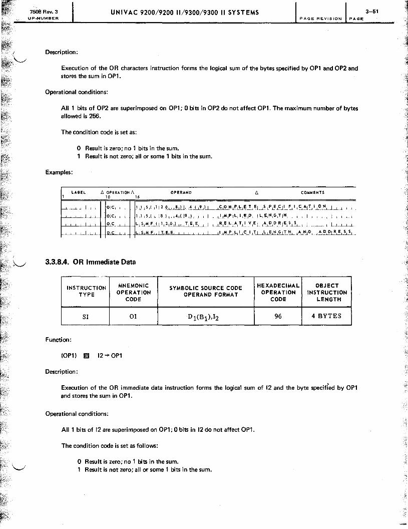
7508 Rev. 3 UP.NUMBER
UNIVAC 9200/9200 11/9300/9300 II SYST EMS 3-51 PAGE REVISION PAGE
Description:
Execution of the 0 R characters instruction forms the logical sum of the bytes specified by OP1 and OP2 and stores the sum in OP1.
Operational conditions:
All 1 bits of OP2 are superimposed on OP1; 0 bits in OP2 do not affect OP1. The maximum number of bytes allowed is 256.
The condition code is set as:
o Result is zero; no 1 bits in the sum. Result is not zero; all or some 1 bits in the sum.
Examples:
LABEL !::, OPERATION !::, OPERAND !::, COMMENTS 1 10 16
-'-~" _1-'-_--' _ _ 9l'-c--' __ 1 1 L'.LS,( --,1j~&L'-1!.lllu~.ci-,9,LL-'---'--<:1'0M lPlL}~2" El __ ,S LP,e E11_, ':.LI-,-CLAjT.lI-,--~,~_J--'_LL.L -'---'----'----"- l--L--'_ QjC1 , [ 1 [I lS1! [, j8,udA..ci19 d [ 1 [J _l.LI,MIPLLLI,~,D, [LLE,N1G,TjH, 1 ) ) 1 1 1 1 .1 l_J _I L 1
I Ol~.l_~ L~&.F'.L( I 1 12 10 I) I' 1.!6.~L.LL~6L 1~"S.~ I'! l~_L...LA .L~~E~~_LL L-'----'...LLLLl.-'-__
I --'- ~-'---' - 1..L~,M, F,~lL~E, I I IL_LL.L--L--'~j!-,l--,C--'-'.J T_L.LL..L~&T, t-I.c. l~.l.Nl D [ .1 ~lE.cP.L~,~_
3.3.8.4. OR Immediate Data
INSTRUCTION MNEMONIC SYMBOLIC SOURCE CODE HEXADECIMAL OBJECT
TYPE OPERATION OPERAND FORMAT OPERATION INSTRUCTION CODE CODE LENGTH
SI 01 Dl(Bl),12 96 4 BYTES
Function:
(OP1) IiJ:l 12~OP1
Descri pti on :
Execution of the OR immediate data instruction forms the logical sum of 12 and the byte specified by OP1 and stores the sum in OP1.
Operational conditions:
All 1 bits of 12 are superimposed on OP1; 0 bits in 12 do not affect OP1.
The condition code is set as follows:
o Result is zero; no 1 bits in the sum. Result is not zero; all or some 1 bits in the sum.
-~

7508 Rev. 3 UP.NUMBER
Examples:
1 LABEL
UNIVAC 9200/9200 11/9300/9300 II SYSTEMS PAGE REVISION PAGE
t::. OPERATION t::. OPERAND t::. COMME 10 16
I ole 1 1 5 ( 112 0 8 ) I, .. ( 9 "~~~~.t!..c~LL~~El'--'':..t~e~l!ll~L . .L.L.LL 1
I IOle .L.L. .. LJ~.c.l.lL.l!.J...u.d.ti.l9...cl.L1. .. l.L ..l •. L 1..tII4l!'..LLc!ll:-'.Q.L.. L ~l!'.1'1-'-"-'.U t:!l. 1 L 1 1 l l." 1.1.-'-_1.-'._l 1
I ole LSIIIF(1120) ,IT l! E I REL~~IEI ,",D,D,RIE,S,S, , 1 .LLJ I I I I I I I
I lole, L S III F IT E E I I I III P I L.l.!...cS!.J.T I ,L,E,N,GIT,H, ,,,,NIDL~~~
3.3.9. Supervisor Instructions
The supervisor instructions execution affects the contents of the lower bytes of main storage. The instructions store or modify one of the program state control words or communicate between operator and problem program. The supervisor instructions are:
Mnemonic
LPSC SPSC SRC
Function
Load program state control Store program state control Supervisor request call
Format
SI SI SI
While there are technically no "privileged" instructions on the 9200/9300 series systems, the use of the LPSCISPSC instructions is usually reserved by software convention to the operating system.
The instructions are explained separately in the text and are accompanied by notes on their limitations and operations.
3.3.9.1. Load Program State Control
INSTRUCTION MNEMONIC SYMBOLIC SOURCE CODE HEXADECIMAL OBJECT
TYPE OPERATION OPERAND FORMAT OPERATION INSTRUCTION CODE CODE LENGTH
SI LPSC Dl(Bl),I2 AS 4 BYTES
Function:
(OP1) -+ PSC
Description:
Execution of the load program state control instruction may replace or modify the specified program state control word in low·order main storage. The word specified by the OP1 address, under the control of the bits of the immediate operand 12, is stored at the PSC location.
3-52

7508 Rev. 3 UP.NUMBER
UNIVAC 9200/9200 11/9300/9300 II SYSTEMS 3-53 PAGE REVISION PAGE
Operational conditions:
1. The storage area specified by OPl must be defined on a half·word boundary.
2. The functions of the OP2 bits are:
1 byte -------OP2 I xlxlxlxlxlxlolol
o 7 Bits
where:
x May be either a 1 bit or a 0 bit, depending on the programmer's requirements.
Bits 0,1 control the loading of the PSC word and the ASCII bit.
0,1
00 PSC word remains unchanged. 01 Load full PSC word stored at the OPl address. 10 Set ASCII bit in PSC word to zero. 11 Set ASCII bit in PSC word to one.
Bit 2 specifies which PSC is to be affected by the instruction.
2
o Load processor PSC. Load input/output PSC.
Bit 3 specifies which PSC word controls the next instruction executed.
3
o Processor PSC has control. 1 Input/output PSC has control.
Bits 4,5 control the alter function.
4,5
00 Alter state remains unchanged. 01 Restriction to location 4 is removed. 10 Alter is restricted to location 4. 11 Result is unpredictable.
Bits 6, 7 are always O.
Examples:
LABEL l::, OPERATION l::, OPERAND l::, COMMEHT~ 1 10 16
I I , , LIP S C 2 8, ( 1 41 ) XL '.,41° " , , ,CIO,M, P,L,EI T, E, ,S ,PIE,C, I,F,IJC,A, T, I,OIN, , , I LIP S C CHN G .JX"_IO~L'L_L.l_J.-L~LAT,llv,E, .LA,D I D ~~~.L...l.L...l-L

7508 Rev_ 3 UPoNUMBER
UNIVAC 9200/9200 11/9300/9300 II SYSTEMS 3-54 PAGE REVISION PAGE
3.3.9.2. Store Program State Control
INSTRUCTION MNEMONIC SYMBOLIC SOURCE CODE HEXADECIMAL OBJECT
TYPE OPERATION OPERAND FORMAT OPERATION INSTRUCTION CODE CODE LENGTH
SI SPSC D1(B1),12 AO 4 BYTES
Function:
PSC~OP1
Description:
Execution of the store program state control instruction moves the specified program state control word to the address specified by OP1.
Operational conditions:
1. The storage area specified by OP1 must be defined on a half-word boundary.
2. 12, the immediate operand, controls the PSC that is stored; the third bit of the byte selects the PSC word:
Examples:
1
OP2
1 byte ~
lololxlololololol o 7 bits
where:
LABEL
I
I
o = bits not used. x = bit used to select the PSC word:
o Stores the processor PSC; Stores the input/output PSC.
[::, OPERATION [::, OPERAND 10 16
SIP S C 2 2 ( 1 L!llu I X,' ,2 10~, ,CI 01 MI PI LI EI TI EI
SIP S C C HINI GI~~~_--L_~~.L!L I: VI EI
[::, COMMEN-
,SIPIEICI~~.L~~
I A I 0 lP--LRJ.~..2.2.J. I I I I l_L
/
-:-""

7508 Rev. 3 UNIVAC 9200/9200 11/9300/9300 II SYSTEMS UP.NUMBER PAGE REVISION PAGE
3.3.9.3. Supervisor Request Call
INSTRUCTION MNEMONIC SYMBOLIC SOURCE CODE HEXADECIMAL OBJECT
TYPE OPERATION OPERAND FORMAT OPERATION INSTRUCTION CODE CODE LENGTH
SI SRC Dl(Bl),I2 Al 4 BYTES
Function:
12-+SRC
Description:
Execution of the supervisor request call instruction stores the immediate operand, 12, in the SRC portion of the I/O PSC word and sets the interrupt request.
Operational conditions:
1. OP1 is ignored.
2. Interrupt occurs immediately when the processor is under control of the processor PSC word, but is stored when input/output PSC is in control.
3. When the interrupt request is accepted, no device address or status is stored.
4. An I/O operation can be completed when an SRC instruction is executed in the processor mode. The device address and status are stored, making them available when the interrupt occurs.
Example:
LABEL b, OPERATION b, OPERAND 10 16
3-55


7508 Rev. 3 UNIVAC 9200/9200 11/9300/9300 II SYSTEMS UP.NUMBER PAGE REVISION PAGE
4. Assem bier Directives
4.1. DIRECTIVES
In addition to the representation of machine instructions, constants, and storage, the SPERRY UNIVAC 9200/9300 Series Tape/Disc Assembler language includes several assembler directives. These are instructions to the assembler to perform certain functions; they afford the user of the assembler language control of the operation of the assembler.
The assembler directives, grouped by function, are:
Symbol defi nition
EQU
Assembler control
START
END
ORG
LTORG
Base register assignment
USING
DROP
Program linking and sectioning
CSECT
DSECT
COM
ENTRY
EXTRN
4-1
-i

7508 Rev. 3 UNIVAC 9200/9200 11/9300/9300 II SYSTEMS UP-NUMBER PAGE REVISION PAGE
Listing control
SPACE
EJECT
TITLE
I nput control
ISEQ
Assembler directives EQU, END, ORG, USING, DROP, ENTRY, and EXTRN may use one or more symbols in the operand field, and, with the exception of ENTRY, eXTRN, USING, and DROP, the symbols must have appeared in the label field of a previous statement.
4.2. SYMBOL DEFINITION
eQU - Equate
The value and length attribute of a symbol may be defined explicitly. The statement format is:
LABEL !1 OPERATION !1 OPERAND
symbol EQU
where:
e1
and e2
are expressions.
The symbol in the label field is defined as the value of the first expression in the operand field. If the value of the first expression in the operand field is not between 0 and 65,535, the statement is flagged with an error indication and the symbol remains undefined.
The symbol is defined to have a length attribute equal to the value of the second expression in the operand. The second expression in the operand may be omitted, in which case, the symbol is defined to have the length attribute of the first expression.
If the value of the location counter is 2000 when the following lines are detected,
LABEL !1 OPERATION !1 OPERAND !1 1 10 16
TAG I L DIS ~ 2 5 C L 110 J I J I 1 I 1
HiliD E ~ EIQ U I 1 o 0 + TIA G , 1 5jO I I I I I I I I I I I I I I I I
SlE~E I K, 1 I EIQ,U TI A. G,+ 217 ,0 * I I I 1 1 ' , , I I I I I I I I I I I I I I I I
TAG has an absolute value of 2000 and a length attribute of 10. H I DE has an absolute value of 2100 and a length attribute of 150. SEE K has an absolute value of 20 and a length attribute of 10.
4-2
.. J
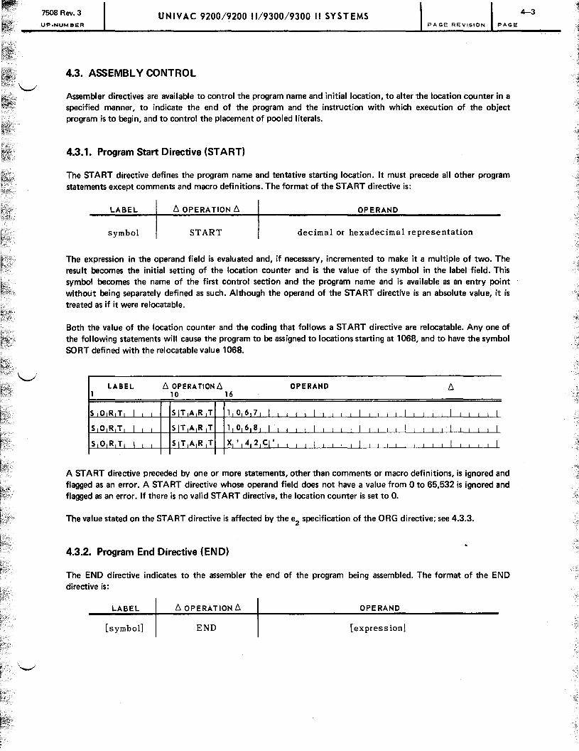
7508 Rev. 3 UNIVAC 9200/9200 11/9300/9300 II SYSTEMS UP.NUMBER PAGE REVISION PAGE
4.3. ASSEMBLY CONTROL
Assembler directives are available to control the program name and initial location, to alter the location counter in a specified manner, to indicate the end of the program and the instruction with which execution of the object program is to begin, and to control the placement of pooled literals.
4.3.1. Program Start Directive (START)
The START directive defines the program name and tentative starting location. It must precede all other program statements except comments and macro definitions. The format of the START directive is:
LABEL /j. OPERATION /j. OPERAND
symbol START decimal or hexadecimal representation
The expression in the operand field is evaluated and, if necessary, incremented to make it a multiple of two. The result becomes the initial setting of the location counter and is the value of the symbol in the label field. This symbol becomes the name of the first control section and the program name and is available as an entry point without being separately defined as such. Although the operand of the START directive is an absolute value, it is treated as if it were relocatable.
Both the value of the location counter and the coding that follows a START directive are relocatable. Anyone of the following statements will cause the program to be assigned to locations starting at 1068, and to have the symbol SORT defined with the relocatable value 1068.
LABEL /j. OPERA TlON /j. OPERAND /j. 1 10 16
S ORT I S IT A R T 1 o 6 7 I I I I I I I
S 0 R T[ I SIT A R T 1 o 6 8 I I I I I I I
S 0 R T( I SIT(AJR T X'42CJ' I I I I I I I I I I I I I I I I ( I I I I
A START directive preceded by one or more statements, other than comments or macro definitions, is ignored and flagged as an error. A START directive whose operand field does not have a value from 0 to 65,532 is ignored and flagged as an error. If there is no valid START directive, the location counter is set to O.
The value stated on the START directive is affected by the e2
specification of the ORG directive; see 4.3.3.
4.3.2. Program End Directive (END)
The END directive indicates to the assembler the end of the program being assembled. The format of the END directive is:
LABEL /j. OPERATION /j. OPERAND
[symbol] END [expression]
4-3
, J
--::J

7508 Rev. 2i UNIVAC 9200/9200 11/9300/9300 II SYSTEMS 4-4
PAGE REVISION PAGE
When the assembler detects an END directive during its last pass, it writes any remaining text data which it has accumulated, then writes a transfer record. If the operand field of the END directive contains an expression, its value .~
is entered in the transfer record to signify the address at which the program execution may begin. If the END directive does not contain an expression in the operand field, the corresponding field of the transfer record is blank.
If a symbol appears in the label field of the END directive, it is assigned the current value of the location counter. This is normally one greater than the highest address assigned to the program being assembled.
4.3.3. Assign Location Counter Origin Directive (ORG)
The ORG directive is used to set the location counter to a specified value. The format of the ORG directive is:
LABEL D. OPERATIOND. OPERAND
[symbol] ORG
The value to which the location counter is set is determined by the values of the expressions in the operand field. If e
2 is not expressed, then the location counter is set to the value of e
1• If e
2 is expressed, the location counter is set
to the next value greater than or equal to the value of e1 which is a multiple of e2
. Some examples follow.
Operand Resulting Location Counter Value
1000 1000,2 1000,16
1000 1000 1008
The value of e2
must be a number that is the result of 2 raised to a power.
If e2
is used, the value stated on the START directive must be a mUltiple of the highest e2
value expressed in the assembly. The assembler assumes a start value of zero until the final pass, when base adjustments are computed. The ORG value of e
2 will be lost if the adjustment factor is not a proper multiple.
Because the beginning address of each CSECT is based on the ending address of the previous CSECT, and ORG*,e2
statement must precede each CSECT directive when such ORG statements are used in the following section, as follows:
LABEL D. OPERATION D. OPERAND 10 16
I I I ., .L
where:
e2
is the highest e2
value used.

7508 Rev. 3 UNIVAC 9200/9200 11/9300/9300 II SYSTEMS UP-NUMBER PACE REVISION PAGE
If a symbol appears in the label field, its value also is the value to which the location counter is set and the symbol is assigned a length attribute of one. The value to which the location counter is to be set must be either an absolute value between 0 and 65,535 or a relocatable value between the initial location counter setting and 65,535. If the value is not within this range, the ORG directive is ignored and the line is flagged with an error indication. With the ORG directive, it is possible to set the location counter to a value that is not a half-word boundary.
The ORG directive to set the location counter to a value 603 less than its current setting would be:
LABEL 6. OPERA liON 6. OPERAND 10 16
The ORG directive may be used to reserve a number of locations that are not expressed as a single decimal integer. For example, to reserve A minus B bytes of storage, where A and B are previously defined symbols, the statement is written as:
Bytes of storage reserved with a OS or ORG directive are not set to zero when the program is loaded.
If e1
is a relocatable expression, the value to which the location counter is set and the coding that follows the ORG directive are relocatable. If absolute, the value to which the location counter is set and the coding that follows the ORG directive are absolute.
4_3.4. Assign Literal Pool Origin Directive (L TORG)
Literals are gathered into one or more pools with elimination of duplicates within one pool at the end of the first control section (4.5.4). An LTORG statement directs the assembler to create a pool from all literals detected since the last l TORG directive or beginning of the program. It also assigns to the pool the present value of the location counter, after adjusting the location counter to a half-word boundary.
The form of the L TORG statement is:
LABEL 6.0PERATION 6. OPERAND
[symbol] LTORG unused
The label, if present, is assigned the value of the address of the first byte of the literal pool and a length ~ttribute of one.
Because literals are gathered into pools before they are generated and the pools are processed as standard specifications, errors are not flagged when the literal is written. Invalid specifications are not discovered until the literal pool is dumped.
4-5

7608 Rev. 3 UNIVAC 9200/9200 11/9300/9300 II SYSTEMS UMBER PAGE REVISION PAGE
4.4. BASE REGISTER ASSIGNMENT
The assembler assumes the responsibility for converting storage addresses to base register and displacement values for insertion in instructions being assembled. To do this the assembler must be informed of the available registers and the values assumed to be in those registers. The assembly directives USI NG and DROP are available for this purpose.
4.4.1. Assign Base Register Directive (USING)
The USING directive informs the assembler that a specified register is available for base register assignment and that it contains a specified value. The format of the USING directive is:
LABEL f:j, OPERATION f:j, OPERAND
[symboll USING
where:
r Is a relocatable or absolute expression and a1 , ••• ,an
are register numbers.
The second and succeeding expressions in the operand field must be numbers from 8 through 15, denoting general registers. The first expression represents the value that the assembler assumes is in the first register at object time. That number, plus 4096, will be assumed in the second register, and so on. Thus, if the label 'ABC' has a value of 400, the statement
LABEL f:j, OPERATION f:j, OPERAND 10 16
I I I I
informs the assembler that, at object time, general register 12 contains the value 400, general register 9 contains the value 4496, and general register 13 contains the value 8592.
The registers must be loaded with the correct values by the user program. For instance, the instructions for the situation described previously would be:
t--'--'--'--"-LL.L._ ~~LllN..1.G __ +-+-A-L~ .. .L~.~.J.!l~L! ... l~ I' I 1 i 3 IL .. l..1_i _L __ L.L.L.J---L _L ....... L ..... L..l. __ L .. ~ .... 1 ...... 1. ... 1.
.1 L I H.L.-'--J,-+-+-1.l~1'_J T I A jG ! 1 I .. ..LI -11--'-.1 -,--,-I -11 .... ! I 1 Lml.mL_.L.L.L.LLl....L.Lm.lmL..L
LIH _L_L.. 9. T Al~!2 I I 1. ... LJ.I---'-_Iw. . ..1.I_LL..Ll...L_.l ..... l ..... .l .. -.L..L..l .... l .... LL.1... .... 1. ... L
I 1,3,. T AIG 3 I , 1 I , I I
J .. J f-..--!-L.L.....L.-..£.-'----'-t-t--'--'--'-... -L .. t-t-'--'-.L! I , Im~'---'----'----'---.. L..L-.L..L.-'- .. .l ...... L.L....L.....l._J ... -'I'---'---'---'I_ .. .l. ...... L
T A IG I1 I I I. DIC L-1_+-+-y
..l....:..(. i~IB ,c I) I '_ .• L .• -,-'--,---'-..-,-I •. Lm .. L.L_L_L . ..l .• L_..I.......JLL......lL ....... IL ..... L--'t---'.......L ..... L .... L_.Ll
T,A G 2 L....J.....-'--+--~~D_.LS.-'--'--t_+y j ( IA ,B I C.L~ ,4! 0 i 9 I 6 L!.t 1 I I I .. .L I 1 Im1.' I I L ...... , -,--,--,-_L TI' G 3 I o.l~ V ( A B CL:,8,1 ,9121~.L....L.....l....L ... .l.LL.....L-i I I I
:1, 1 I I I ; i
--~
-:§

7608 Rev. 3·· UP.NUMBER
UNIVAC 9200/9200 11/9300/9300 II SYSTEMS PAGE REVISION PAGE
...-.... 4.4.2. Unassign Base Register Directive (DROP)
\......I The format of the DROP directive is:
LABEL /:::,. OPERATION /:::,. OPERAND
(symbol] DROP
where:
a1 ,···,an Are absolute expressions, each with a value from 8 through 15.
Each expression denotes a general register that no longer contains a value available to the assembler for computing base register and displacement values.
4.4.3. Function of USI NG and DROP Directives
T he assembler maintains a table of the available registers and the values they contain at object time, the USI NG table. A USI NG directive adds a register and value to the USI NG table, or revises the value for a register already in the table. A DROP directive removes a register and its associated value from the table. If the operands of a USING or DROP directive are not valid, the directive is ignored and the line is flagged with an error indication.
If an operand address is given as a relative address instead of a base register and displacement speCification, the assembler searches the USI NG table for a value yielding a valid displacement; that is, a displacement of 4095 or less. If it finds more than one such value, that value yielding the smallest displacement is chosen. If no value yields a valid displacement, the operand address is set to zero and the line is flagged with an error indication. If more than one register contains the value yielding the smallest displacement, the highest numbered register is selected.
An absolute address with no indicated base register is treated as an absolute, direct address unless an appropriate value is found in the USI NG table.
The placement of a USI NG directive determines the generation of operand addresses within instructions, based on that USING statement. The first operand of the USING statement determines the portion of the program that may be addressed using the specified register. Thus, if a program contains the coding
LABEL /:::,. OPERATION /:::,. OPERAND /:::,. 1 10 16
I lUIS I N G B 1 0 I I I I I I . At i I I 1 L1Hi l 1 0 , B I I I I I I I I I I I I I I I I I I
1 I ·1 i I I I I I I
I • j I 1 I I I I I 1 i l I I
I I · I I I I I I I I I I
B I DIC Y ( C ) I I I I I I I I I I I I I I I I I I I I I I .L C l 1i D~S C LI 1
101 I I I I I I I I I I I I I I I I I I I I I I I I I I
I · I I I I I I I I I I I I I I I I I I I I I I I I I I I · I I I I I I I I I I I I I I I I I I I I I I I I I
I · L1 I I I I I I
--~

7508 Rev. 3 UP.NUMBER
UNIVAC 9200/9200 11/9300/9300 II SYSTEMS 4-8 PAGE REVISION PAGE
the B2 and 02 fields of the instruction labeled A contain 10 and 0, respectively. Moreover, if the program contains no USING directives for register 10, other than those shown, the second line, labeled A, is the only line in the .. ----./ program for which the assembler would consider 10 as a register available for addressing the line labeled B.
The SPERRY UNIVAC 9200/9300 Series operating system locator/loader routine places the transfer address of a main program in processor register 15 prior to transferring control to it. All other registers must be loaded by the program itself in a manner consistent with the information given to the assembler in the USING directives. The following example shows how this is done.
LABEL b. OPERATION b. OPERAND b. 1 10 16
1 I uls I NG A 1 5 I I I I I I I A I LIH 1 2 , B I I I I I I
I I UIS I NG C 1 2 I I I I I I I
I · I I I I I I I
I I I I · I I I I I I I I
I I · I I I I I I I
B I 1 DIC, I Yi(,C,)J I , I it i -' I I , I I I I I I I I I , I I I , .1 I , · I , .1 , J I I , I I I
I · I I , I I I I I
I · I I I I I I I
C I DIS C L 1 0 I I I I I 1. I · I , I I I I I 1 I
I . I I I , I I , I I , I , I I I I , I I , I I I I I I I . I I I I I I I
I EINID AI I I I I I I I
Lines .2 and 3 of the example exemplify the following general rule:
An LH instruction to load a value into a general register must precede the USING directive, which informs the assembler that the value is available.
Also, it is possible to specify an absolute value for the first expression in the operand of a USING directive. The entry in the USING table made in response to such a USING directive is not used to break down relative addresses. It is used, instead, to break down absolute addresses. For example, given the following coding,
j.: : : : : : : II~:~: ': ":GII::::~:::; :;::: : : : : : : : : : : : : : : : : : : : : : : : : the B2 and 02 fields of the instruction labeled A will contain 15 and 96, respectively.

7508 Rev. 3 UP-NUMBER
UNIVAC 9200/9200 11/9300/9300 II SYSTEMS ........ PAGE REVISION PAGE
4.4.4. Direct Addressing
The machine instruction format provides base register and displacement addressing (indexed addressing) or direct addressing. Instructions using direct addressing have a faster execution time. To facilitate error checking by the assembler, direct addressing is described to the assembler in terms of the pseudo base registers 0,1,2,3,4,5,6, and 7, which contain the values 0,4096, 8192, 12,288, 16,384,20,480,24,576, and 28,672, respectively. Thus, the direct address 512 would be treated, by the assembler, as an address consisting of a reference to the pseudo base register 0 and a displacement of 512. The address 4098 would yield a base of 1 and a displacement of 512. The address 4098 would yield a base of 1 and a displacement of 2. The additional forms of the USING directive available for direct addressing are, specifically:
LABEL b. OPERATIONb.
USING .USING
USING
OPERAND
*,0 *,1
*,7
The first line makes direct addressing available for addresses in the range 0 to 4095. The second makes direct addressing available for addresses in the range 4096 to 8191, and so on. The DROP directive also may refer to the pseudo registers 0 through 7 to terminate direct addressing.
A program involving direct addressing still may be relocatable.
When used in the operand of the USING directive the asterisk (*),.does not indicate the current value of the location counter.
Both general registers and pseudo registers may not be specified in one USING directive.
4.5. PROGRAM LINKING AND SECTIONING
The assembler provides, as part of its output, information that allows the results of separate assemblies to be linked, loaded, and executed as a single program. Proper partitioning reduces the machine time required to make changes to an existing program. If a change is required, only that part which is changed need be reassembled. The output is then linked with the remaining parts to produce the altered program. Proper partitioning of a program also reduces th~ number of symbols required in each of the separate assemblies.
A symbol defined in the label field of module A and addressed in module B is said to be defined in module A and referenced in module B. Thus, by using the ENTRY and EXTRN directives, proper linkage is supplied when the separate modules are assembled. This information is given to the linker program by the external definition records and the external reference records which are outputs of the assembler and inputs to the linker.

UNIVAC 9200/9200 11/9300/9300 II SYSTEMS P.NUMBER PAGE REVISION PAGE
4.5.1. Identify Entry·Point Directive (ENTRY)
That portion of a program submitted as input to a single assembly is called a module. Each module must declare the symbols defined within that module to which reference is made by other modules. These symbols are declared by the ENTRY directive. The directive format is:
LABEL 6. OPERATION 6. OPERAND
unused ENTRY symbol,symbol, ... ,symbol
Each symbol in the operand field is defined by its use as a label in a line of code within the module and referenced by one or more separately assembled modules.
4.5.2. Identify Externally Defined Symbols Directive (EXTRN)
The assembler must be informed of all symbols defined in other modules and referred to in the module being assembled. These symbols are declared by the EXTRN directive. The directive is:
LABEL 6. OPERATION 6. OPERAND
unused EXTRN symbol,symbol, ... ,symbol
Each symbol in the operand field is defined in some other module.
4.5.3. Sectioning
The assembler also permits sectioning of input to one assembly. Dividing a program into sections is optional; therefore, when writing unsectioned programs, the programmer does not need to know the points stressed in the following discussion and the discussion of CSECT, DSECT, and COM.
In a program without CSECT or DSECT sectioning directives, the entire program is one section that begins with the START directive and ends with the END directive. If, however, sectioning directives are used, the first section of the program begins with START and ends with a CSECT or DSECT sectioning directive, which also indicates the beginning of the next section. Each subsequent sectioning directive informs the assembler of the end of one section and the beginning of the next. The last section of the program ends with the END directive. The sectioning directive of each section is named by a label.
LABEL 6. OPERATJON6. OPERAND 6. 1 10 16 . PRO G I S IT ART 1 0 6 8 I J 1 i I I I I I 1 1 I
A B L E I UIS I N G PR QG,ll 2, 9 , j 1 3 I I I I
I :1_1 _1 _I 1 1 1 1 1 1 1 I 1 1 I 1 I 1 1 1 I I
FROG I q Si EI CI T _I 1 J 1 1 I 1 1 I I I I
B A K E I DIS 25 CL 110 I I I I I
I : I I I I J 1 L
4-10
---"?"
-~

7508 Rev. 3 UNIVAC 920019200 11/930019300 II SYSTEMS UP.NUMBER PAGE REVISION PAGE
(cont.)
LABEL /:::,. OPERATION /:::,. OPERAND /:::,. 1 10 16
T R 0 G I CIS ECT I I I I I I
C H A R I OIR G 4 0 0 0 ,1 4 I 1 I I I
I : I I 1 L j I 1 I I I
D RIO GI I I DIS ECT I I I I I I I I
I : I I 1 I I 1 I 1J I 11...
IN MiRE 1 EIN D 1 1 I 1 1 I
ABLE is within a section named PROG; BAKE is within FROG; and so forth. The last section, a dummy control section, ends with the END directive.
A control section is a group of instructions, constants, and storage areas where positions relative to each other are fixed, and must be preserved for proper coding performance. An instruction in one section must not depend on its positional relation to instructions or data in another section for its proper execution. Sections appear in the input to the assembler in any order along with statements belonging to one or more other sections. The first control section begins with the first source statement. If the first statement is a START directive, its label becomes the name of the first control section.
4.5.4. Control Section Identification (CSECT)
The CSECT directive indicates to the assembler that the source statements that follow belong to a control section different from other preceding source statements. Use of the CSECT directive allows the programmer to code parts of the logical sections of a program in the order in which he determines the need for them. The format of the CSECT directive is:
LABEL /:::,. OPERA TION /:::,. OPERAND
[symholl CSECT unused
The label field of the CSECT statement contains the name of the control section. This symbol must not appear in the label field of any other source statement except another CSECT statement. It is the name of the control section and is defined as an entry point of the program being assembled. The value of the symbol is the address of the first byte of the control section. If the label of the CSEcr statement has appeared as a label of previous CSECT statement, the succeeding statements are a continuation of the control section of that name.
A programmer may find the use of CSECT convenient if, in the past, it was necessary to discontinue coding a section of a program to code another section upon which the original section is dependent. Shuffling of coding sheets is eliminated by setting up the new section with a CSECT directive and continuing. After the second logical section is coded or even partly coded, the programmer can revert to the original section by writing a CSECT directive with the same label given to the original section. The assembler reorganizes parts of each section and assembles it as one continuous control section. It is important to note, however, that neither the listing nor the sequence of object coding is reorganized. The reorganization that takes place is with respect to the final structure of the coding within main storage after loading; the addresses of the coding within main storage are indicated on the listing.
4-11
..~
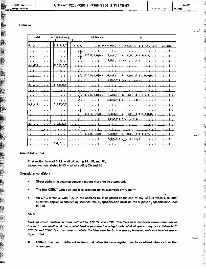
UNIVAC 9200/9200 11/9300/9300 II SYSTEMS .uMBER PAGE REVISION PAGE
Example:
LABEL !::,. OPERA TIOM!::,. OPERAND !::,. 1 10 16
B ILL I 51T A RT 1 0 6 5 I * IA U TO MIA TIC AIL L Y 51E T 5
I I I I I I I
I l IC 0 D~ I NIG : PAIR T ~ 10 F IF II ~5 T
I I J L 5 EjC T I 0141 ( 1 A ) I
M I K I I CI5 E C T I I I I I
I I ,\ I I I I I
I I .?I IC 0 D I NIG : PAIR TI IAI 10lFI 151 EI C 10 I t!d:~1
I I I I /1 I I I I I I I I IS lEI CITIII 01 141 1'12 1AIII I I I
B ILL I CIS E C T I I I I I
I I I I I I I I
I I IC 0 D I NIG: PAIR T ,a. 10 F F I IR 5 T
I I ,J I I 5 EIC Til ,0,141 ( 18,) I
M I K I I Cj5ECT I I I I I I I I I I I I I I I I I I I I I I I I I I I I
I I ~I I J J I
I I ~, IC 0 D I NIG : P,At R T B 10, F 5 EIC ON D
I I J I I 5 E(C T I 0141 ( 2 B) I
B ILL I CIS E C T I I I I I
I I I) I I I I I I I I I I I I I I I I I I I
I I (, IC 0 D I NIG: PAIR T C 10 F F II R 5 T
I J / I I 5 EIC T I o 141 ( 1 c,) I
I EIN D I I
Assembled output:
First section labeled BILL - all of coding 1A, 1 B, and 1C; Second section labeled MIKI- all of coding 2A and 2B.
Operational conditions:
I
• Direct addressing between control sections must not be attempted.
I
• The first CSECT with a unique label also sets up an automatic entry point.
I
I
I
I
I
UIP C 5 EIC T
I -1-1 I I I I
1 I
I I
I I
I ~
I I I I I I I I
I I I I I I I I
I I
I I ,
I I I I I I I
I I
I I I I I I I
J • J
I I
I I
I I
I I I I I I I
I I
I I
I I
• An ORG directive with *,e2 in the operand must be placed at the end of any CSECT when such ORG directives appear in succeeding sections; the e2 specification must be the highest e2 specification used (4.3.3).
NOTE:
Modules which contain sections defined by CSECT and COM directives with duplicate names must not be linked to one another. A blank label field is permitted as a legitimate label of spaces only once. When both CSECT and COM directives have no labels, the label used for both is spaces; however, only one label of spaces is permitted.
• USING directives in different sections that define the same register must be redefined when each section is reentered.
4-12
~--~-,

7508 Rev. 3 UP.NUMBER
UNIVAC 9200/9200 11/9300/9300 II SYSTEMS 4-13 PAGE REVISION PAGE
4.5.5. Dummy Control Section Identification (DSECT)
The DSECT directive indicates to the assembler that the statements which follow are used to redefine a data storage area reserved either in the module being programmed or on another separately assembled module. If the data storage area is reserved in a separately assembled module, that module is later linked to the module containing the dummy control section. No storage is reserved for a dummy control section. Data and instructions appearing in a dummy control section do not become part of the assembled program. The format of the DSECT statement is:
LABEL ~OPERATION ~ OPERAND
[symbol] DSECT unused
A DSECT statement may not contain a blank label field in a program that either contains no START statement or contains a START or CSECT statement with a blank label field.
An LTORG directive may not appear in a dummy section. Labels of statements in a dummy section are called dummy labels.
The following rules must be observed in the use of dummy labels:
• An unpaired dummy label may appear only in an expression defining a storage address for a machine instruction or a constant of type S.
• A base register may not be designated for this address field, but the resulting value must be covered by a USI NG statement.
• The programmer must ensure that the appropriate value is loaded into the register specified in the USING statement.
The last source code input to an assembly must not be part of a dummy control section.
More than one dummy control section can be used within a module.
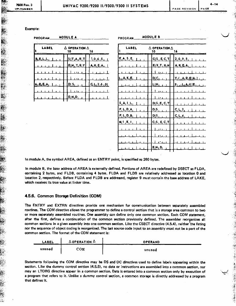
7508 Rev. 3 UP.NUMBER
UNIVAC 9200/9200 1119300/9300 II SYSTEMS PAGE REVISION PAGE
Example:
PRoGRAM ____ ~M~O~D~U~L~E~A~ __________ ___ PROGRAM __ ~M~O~D~U=L~E~B~ ________________ ___
LABEL b. OPERATIoN b. LABEL b. OPERA TlON b. 1 10 16 1 10 16
B,E L,L I I SIT ART 1 0 6 5 I E A S E I qs E C T 209 5 I
I EIN TRY AREA I I EIX T RN IA.REA I
I I I I I I I I I,
, I I I 1 i I L A K E I i D1Ci i YIC A R EIA,)
A,R.E A I DIS CL26 01 I I LIH 9 LA KIE
I I I I I I
I I EINID I I I I 1 ~1 -' II J ~. Ii I I I
SAIl L I DIS E C T I I I I I I I I
FLDA I DIS CL2 I
FLDB I i D1Si i L£..L 4 I
M I K I I CIS ~ C T I
Ii i i I
I I . I I I I I I I I
I I I
I EINID 1 I
In module A, the symbol AREA, defined as an ENTRY point, is specified as 260 bytes.
In module B, the base address of AREA is externally defined. Portions of AREA are redefined by OSECT as FLOA, containing 2 bytes, and FLOB, containing 4 bytes. FLOA and FLOB are relatively addressed as location 0 and location 2, respectively. Before FLOA and FLOB are addressed, register 9 must contain the base address of LAKE, which receives its true value at linker time.
4.5.6. Common Storage Definition (COM)
The ENTRY and EXTRN directives provide one mechanism for communication between separately assembled routines. The COM directive allows the programmer to define a control section that is a storage area common to two or more separately assembled routines. One assembly can define only one common section. Each COM statement, after the first, defines a continuation of the common section previously defined. The assembler reorganizes all common sections in a given assembly into one common section. like the CSECT directive (4.5.4), neither the listing nor the sequence of object coding is reorganized. The last source code input to an assembly must not be a part of the common section. The format of the COM statement is:
LABEL b.OPERATION b. OPERAND
unused COM unused
Statements following the COM directive may be OS and DC directives used to define labels appearing within the section. like the dummy control section (4.5.5), no data or instructions are assembled into a common section, nor
4-14
mayan L TO RG directive appear in a common section. Data is entered into a common section only by execution of '''d a program that refers to it. Unlike a dummy control section, a common storage is directly addressed by a program that defines it.
-.-~
:~

7508 Rev. 3 UP.NUMBER
UNIVAC 9200/9200 11/9300/9300 II SYSTEMS PAGE REVISION PAGE
~ When several routines defining common storage are linked, the resulting module contains only one common section, "'--'" corresponding to the longest common section in any of the input modules. The linker places the one common
section above the highest address of any module or above job control's highest address, whichever is larger (Figure 4-1). In addition to being common to more than one module making up a loadable program, the common section can be made common to more than one link in a chain of programs by use of the CHAIN command card (Section 8). When programs are chained, the linker relocates the common section above the highest location in any chained program.
,r-..
\..../
NOTE:
The linker always relocates the common section to an addl'fJss higher than the highest located phase and higher than job control.
PROBLEM PROGRAM - -"-- -LOCATION PHASE 1 PHASE n
1000 1000 1000
MODULE A MODULE X
4999
JOB CONTROL 5800
MODULE B MODULE Y 5999
6999
7000
7999 (UNUSED)
8000
COMMON SECTION
Figure 4- t. Relocation of the Common Section

7508 Rev. 3
~Y1"~UMI!I£R. '
UNIVAC 9200/9200 11/9300/9300 II SYSTEMS PAGE REVISION PAGE
Example:
PROGRAM __ ~M~O~D~U~L~E~A=-________________ __ PROGRAM ____ ~M~O~D~U=L=E~B~ ____________ __
LABEL b. OPERATION b. LABEL b. OPERATION b. 1 10 16 1 10 16
MODA I SIT ART I MOD B I S IT ART I
I I I I I I
I 1 1 II' I 3, I I I I ClOiM.!l 1 I I I I I
1, L I I Clo M I I I I RIEIC A I DIS YI ( P R OIB l )
R E C A I J I Dlel J Y-1L PI R101B ,) R-.1 EI CLBI I I I DIC1 C, DIAITIE'I
RECB I DIC Co' D A TIE' AREA I DIS 10CL8100
AIR E A I DIS 10C L 810 ° . INFL I DIS CL80 I
I NFL I DIS C1L I8 1
01 I I I I I L I ST I CiS E C T I I I I I I I
OU F L I, DIS CL80 I 1 I , I
I I I I I I I I I I I , I I
G ? F T I CIS E C T I L EIN D 1 . J -1
I I I
2 , I CIO M I I I I I I l I I
T J K I DLC ~L5 ' SIE V E,N '
JOBA I DIS I CL8 ° I G ?IF 11 I I CiS I E CI T 1 I I I 1
I I I I I I I 1'1 I 1 I I I I 1.1.1 L
I. I I I I -.1J I I I I I .1 J
I EIN D I
-."f
.'..J
7508 Rev. 3 UNIVAC 9200/9200 11/9300/9300 II SYSTEMS UPoNUMBER PAGE REVISION PAGE
In module A, two common storage areas are defined by lines 1 and 2. The COM specified by line 2 is a continuation of the COM specified by line 1.
In module B, the COM specified by line 3 uses the common storage area initially defined by line 2.
NOTE:
Modules which contain sections defined by CSECT and COM directives with duplicate names must not be linked to one another. A blank label field is permitted as a legitimate label of spaces only once. When both CSECT and COM directives contain no labels, the label used for both is spaces; however, only one label of spaces is permitted.
4.6. LISTING CONTROL
One output of the assembler is a source and object code listing. An assembler directive is available to control the listing content.
4.6.1. Listing Content Control (PRINT)
The PRINT directive provides control over the listing content.
The following are available options:
• No listing
• Listing not including lines generated by macro instruction calls
• Listing including all lines
The format of the PRINT statement is:
LABEL 6. OPERATION6. OPERAND
unused PRINT a
where:
a Is ON,GEN to print the lines generated by a macro instruction.
. ON, NOGEN to print the macro call, but not to print the lines generated by a macro instruction.
OFF to produce no listing, except for lines on which errors were detected.
One PRINT statement controls the listing of source and object statements until the next PRINT statement is detected among the source statements. The settings before the first PRINT statement are ON and GEN. The settings for operands omitted in a PRINT statement are not altered by the PRINT statement.
.~
j 1
~ i I
1
J 1
I

UNIVAC 920019200 11/930019300 II SYSTEMS BER PAGE REVISION PAGE
4.6.2. Listing Format Control (SPACE)
The SPACE directive provides control over the format of the listing.
The format of the SPACE statement is:
LABEL 6. OP E RA TION 6. OPERAND
unused SPACE a
where:
a Is 0 or blank, which is equivalent to 1 line space.
1-999, the number of lines to be spaced over; form overflow terminates spacing.
Spacing continues until a form overflow condition occurs, at which point a home-paper command is issued and spacing is discontinued.
4.6.3. Listing Format Control (EJECT)
The EJECT directive provides control over the format of the listing.
The format of the EJECT statement is:
LABEL 6. OPERATION 6. OPERAND
unused EJECT unused
The EJECT statement causes a home-paper command to be issued, which results in the next line being a title line on a newpage.
4.6.4. Listing Format Control (TITLE)
The TITLE directive provides control over the format of the listing.
The format of the TITLE statement is:
LABEL 6. OPERATION 6. OPERAND
unused TITLE 'a'
4-18
-~
-,_i .~ .-..-

7508 Rev. 3 UP·NUMBER
where:
'a'
UNIVAC 9200/9200 11/9300/9300 II SYSTEMS PAGE REVISION PAGE
Is a string of up to 54 characters.
The title line is contained within apostrophes to permit centering of the title in the case of leading blanks. Two consecutive apostrophes are necessary to express an apostrophe within the body of the title. If the apostrophes are omitted, the operand field is still used as a title; however, the data is lett·justified.
The TITLE statement permits identification of many pages of listing under a common title that appears at the top of each page. The operand of the TITLE statement is printed on all succeeding pages until a new TITLE statement is detected. When a TITLE statement is read, the assembler advances the printer form to the top of the next page.
4.7. INPUT CONTROL
The assembler provides optional sequence checking of source statements.
, 4.7.1. Input Sequence Control (lSEQ)
The ISEQ statement directs the assembler to perform a sequence check of the source statements on columns 76-80. The format of the ISEQ statement is:
LABEL 6. OPERATION6. OPERAND
unused ISEQ unused
Sequence checking begins with the source statements following the ISEQ statement. It is terminated by an END statement.
Only one ISEQ directive can be in a source code module, and it must be the first statement in the source code following any macro definitions. The ISEQ directive has effect for source code only. In the absence of an ISEQ directive no sequence check is performed.
4.8. ERROR CONTROL
The assembler provides two indications of errors during an assembly.
4.8.1. User Program Sense Indicator (UPS!) Byte Setting
If an error is detected during assembly, the single bit of the UPSI byte (location X'117'), shown as 1 (00000100), is set to 1. This permits detection of errors by a subsequent program in the job stream or by a / SKIP job control card, providing a / JOB card does not intervene. The assembler never resets this bit to zero; therefore, any error in a series of assemblies may be tested for after the last assembly.
4.8.2. Total Error Count
A total error count is available on the last line of the assembly listing. This line always prints no matter which print options have been chosen. (See 7.4.1 for the format of this final line.)
4-19

"-...J
""~

7508 Rev. 3 UNIVAC 9200/9200 11/9300/9300 II SYSTEMS . UP.NUMBER PAGE REVISION PAGE
5. Macro Instructions
5.1. MACRO INSTRUCTION FORMAT
Each source statement causes the SPERRY UNIVAC 9200/9300 Series Tape/Disc Assembler to take one specific action or represents a single constant or machine instruction. The assembler contains a library facility, where one source statement may result in the inclusion of many lines of code determined by a predefined pattern of code called a macro definition. The macro definition may be contained either in a library of definitions or included with the source statements of the program being assembled. The statement requesting the inclusion of the code is called a macro instruction. If a macro definition is included with the source statements, it must precede any macro instructions referring to it, precede the START card, and may not appear within the source code proper.
A macro instruction is similar in form to a source code instruction. It contains a label (optional), an operation code, and an operand consisting of none or one or more expressions separated by commas. The prime difference is that the macro instruction causes the generation of a series of source code instructions representing a number of assembler operations; whereas a source code instruction causes the assembler to do one specific operation.
The format for a macro instruction is:
LABEL b. OPERA liON b.
[symbol] code
OPERAND
PI ,P2,P3'···'P n,N I=P n+l ,N2=Pn+2,N3=Pn+3'··· ,Nm=
P n+m
The label may be any symbol, but is not necessarily assigned the current value of the location counter. The operation is the name of the macro definition describing the pattern of code to be included. The operand, P1 through P n+m' is a sequence of expressions specifying parameters.
P 1 through P n are positional parameters. P n+ 1 through P n+ m are keyword parameters. A macro instruction may have parameters of either or both types, or none at all.
5.1.1. Parameters
A II positional parameters must be specified before any keyword parameters are specified. The order of the expressions in the operand determines the order of the parameters specified. Parameter specifications are separated by commas. When a positional parameter specification is omitted, the comma must be retained to indicate the omission. Thus, if a macro instruction contains positional parameters and the second is not specified, the operand appears as:
6-1

7508 Rev. 3 UNIVAC 9200/9200 11/9300/9300 II SYSTEMS UP.NUMBER PAGE REVISION PAGE
If the third parameter is not specified, instead of the second, the operand is written
P1,P2
No trailing commas need be included.
The specification of a keyword parameter is:
N=P
where N is the name of the parameter (any symbol of seven or fewer characters is a legitimate keyword name) and P is the parameter specification (a value or a character string). Keyword parameter specifications are separated by commas; however, the comma need not be retained if the specification is omitted. A comma must be between the last positional parameter and the first keyword parameter. The order of the keyword parameter specifications is not significant. For example, if a macro definition contains three keyword parameters, the operand of the macro instruction might be:
or
N2 =P 2,N1 =P 1 ,N3 =p 3
and so on.
A macro instruction may contain positional and keyword parameters with commas separating the specifications. For example, the operand of a macro instruction with three positional and two keyword parameters might be:
The number of parameters that may be specified with one macro instruction depends on how much space is required to store the specifications. One macro instruction may ordinarily specify as many as 50 parameters in its operand. When the operand overflows the space provided in one record, provision is made to continue the operand in the following record by putting a nonblank in column 72. The continuation of the operand begins with column 16. The macro pass of the assembler searches for a continuation record as soon as one of the two following events occurs:
• Information is taken from column 71 of the current record .
• A comma, followed by a space, is detected in the current record .
Columns 1 through 15 of a continuation record must be blank. If the information in a record is terminated prior to column 71 by a comma followed by a space, comments may be written after the space. For example, a macro instruction with three keyword parameters might be written as:
LABEL b,. OPERATION b,. OPERAND 1 10 16 72 80
1 1 ~ I MlA e R 0 N 1 = P II, eOMIMENT I I X I
J I "" 2 = P 21, eo MIM E N T I I X I
~. J J I I I I I I N3=P31 elOMIM E N T I I 1
The specification of a parameter may not contain an equal sign or a comma, and may have a maximum of 127 characters.
5-2

7508 Rev. 3 UNIVAC 9200/9200 11/9300/9300 II SYSTEMS
UP.NUMBER PAGE REVISION PAGE
5.2. WRITING MACRO DEFINITIONS
The routines for the macro library are written in standard assembler source code and entered in the library by the librarian. To distinguish one macro from another in the library, three directives are used: PROC, NAME, END.
• PROC directive
The first source code statement of a macro definition is a PROC directive in the format:
LABEL l:::. OPERATION l:::. OPERAND
[symbol] PROC [operands]
The label may be any symbol, but is optional and, when used, the label in the macro instruction is substituted for the PROC label wherever the PROC label appears. For example, if the symbol MOVE were specified for the label of a macro instruction; and the label of the PROC directive of the associated macro definition were NAME, and an instruction within the macro definition were to contain the following line of source code,
LABEL l:::. OPERATION l:::. OPERAND 10 16
then the source code generated by the definition would appear as:
If the PROC directive does not contain a label, but the macro instruction does, that label will remain undefined.
• NAME directive
The second line of a macro definition must be a NAME directive in the format:
LABEL l:::. OPERATION l:::. OPERAND
symbol NAME [operand]
Symbol is the name by which the macro definition may be called, and is the name specified in the operation field of the macro instruction calling it. As many as eight characters may be in a label; the first must be alphabetic, the others alphanumeric.
5-3

7508 Rev. 3 UNIVAC 9200/9200 11/9300/9300 II SYSTEMS UP.NUMBER PAGE REVISION PAGE
• END directive
The end of a macro definition is indicated by an END directive. It has no operand and requires no label.
If the following macro definition is in the library,
LABEL tJ. OPERA TION tJ. OPERAND tJ. 1 10 16
I PIR 0 C I I I I I I I
M ~O IVI E I I [ l NjA[M[E[ i I I I I I I I I I
_I I Ll M1V C1 1 DiE IS IT, lOR IG I I I I I I I I I I I I I I I I I I I I I I EIN D I I I I I I
the macro instruction
is equivalent to the source code instruction:
Note that none of the directives (PROC, NAME, END) is output of the macro pass.
5.3. INCORPORATING PARAMETERS INTO MACRO DEFINITION COOING
The operand of a PROC directive, when used, is:
The first expression, p. in the operand is a symbol used to address the parameters within the macro definition. This expression and its use are explained in this section. The second expression. n. is the number of associated positional parameters. N, •... ,N
m are the names of the keyword parameters. Any symbol of seven or fewer characters is a
legitimate keyword name. Listing the keyword parameters in this way makes them positional parameters to the macro definition.
For example. if the PROC directive is the following format:
LABEL tJ. OPERATION tJ. OPERAND
unused PROC
The macro definition contains three positional parameters, P1
, P 2' and P3 , and three keyword parameters, N1
, N2
,
and N3
. Thus, the keyword parameters become, in effect, positional parameters P 4' P 5' and P 6.
5-4
":;;.

7508 Rev. 3 UNIVAC 9200/9200 11/9300/9300 II SYSTEMS UP.NUMBER PAGE REVISION PAGE
The value specified for a parameter is substituted in the coding for the expression:
where p is the first expression in the PROC directive operand and n is the number of the positional parameter. The first is numbered 1, the second, 2, and so forth. As an example, if the following macro definition is in the library,
LABEL l::,. OPERA TION l::,. OPERAND l::,. 1 10 16 ...
1 ! I P(R 0 C P 0 iDlE S T LJG T H OIRLI G li 1 1 II i iLl..
M 0 V E 1 NIA MEl 1 J J 1 I 1
I 1 MIV C P I( 11) I( IP I( 12 ,) I) I, IP ( 3 ) I I I , I I 1 1 I
1 EIN D 1 1 I 1 1 I I 11 .1
the macro instruction
is equivalent to the source code instruction.
A keyword parameter also is addressed by preceding its name with an ampersand. Thus, the MVC instruction within the macro definition of the previous example could have been written:
If a parameter whose value is not specified in the macro instruction is a complete term in an expression containing more than one term, it is replaced by the value zero; otherwise, it is replaced by the null character string (the character string that contains no characters).
5.4. NAME DIRECTIVE
More than one NAME statement may follow the PROC statement of a macro definition. (All the NAME statements must immediately follow the PROC statement.) Each such NAME statement specifies a different name by which the same macro may be called.
5-5 l :I
J I 1 j
--1

7508 Rev. 3 UPeNUMBER
UNIVAC 9200/9200 11/9300/9300 II SYSTEMS 5-6 PAGE REVISION PAGE
The object of giving more than one name is to permit reference to different versions of the procedure embodied in the macro definition. The versions are distinguished by the operands of the NAME statements. ..---.,/
Only one expression may appear in the operand of a NAME statement and may be assigned a value ranging from zero through 65,535. This expression is essentially a parameter of the macro and may be addressed within the macro definition as:
p(o)
where p is the first expression in the PROe statement operand; consequently, it may be used to distinguish between versions of a macro definition.
For example, if the following macro definition is in the library,
LABEL fj. OPERA TlON fj. OPERAND fj. 1 10 16
I I I PIR Ole P.J I 1 J J _I I I I I
MV4 1 J HIA ME 4 1 _l I I I II . .1 I I I I I
MV8 I HIA M E 8 I I I I I I
I IMIV,C I)"::,~,T'{ Ip,{ 01\ 1\ I jhR,IIGI I I I I I I I I I I I I I I I
I I I I I I EIN,D, I I I I I I I I I I I I I
the macro instruction
I I I I I I I I I IMIV ,4 , I I
would produce the source code
I 1 I I I I I I
I IM,Vlc,
I ID,E,S,T ,( 14,) I' ,O,RII,G,
and the macro instruction
I I I I I I I I
IMIV,S , I I I I 1
would produce:
I I I I I I IMIVICI I IDIEISITI( 18,) I. IO,RIIIG,
./
~
"-.../
"-:
-, ~
-=-.
~.

r
V
7508 Rev. 3 UP·NUMBER
UNIVAC 9200/9200 11/9300/9300 II SYSTEMS
If a NAME statement contains no operand, the parameter p(O) is assigned a value of zero.
PAGE REVISION PAGE
If a macro definition contains no parameters and it makes no reference to the operand of any of its NAME statements, its PROC statement has no operand.
If a macro instruction requests the inclusion of a macro definition of a given name, and, if one with such a name is included in the source statements of the program being assembled, it is included, even if one of the same name is in the macro definition library. The user may override a library macro definition with a macro definition of his own.
5.5. BUlL T·IN MACRO DEFINITIONS
The following names must not be assigned to macro definitions because they are already assigned to macro definitions permanently built into the assembly structure:
CLOSE READ lBRET
CNTRl SETl ESETl
GET TRUNC EOJ
OPEN WRITE MSG
PUT WAITF CANCl
FETCH
5-7


7508 Rev. 3 UP-NUMBER
6.1. GENERAL
UNIVAC 9200/9200 11/9300/9300 II SYSTEMS 6-1 PAGE REVISION PAGE
6. Conditional Assembly Instructions
The SPERRY UNIVAC 9200/9300 Series Tape/Disc Assembler recognizes certain directives that can exclude lines of coding from the output of the assembly, include a set of lines in the output of the assembly more than once, and can establish and alter values that may be used to determine whether a set of lines shall be included or excluded.
These directives are for use within a macro definition to control the pattern of generated coding, based on the parameters supplied by the macro instruction.
6.2. DO AND ENDO DIRECTIVES
A DO directive controls the inclusion or exclusion of the lines following it up to its associated ENDO directive. For example, in the following sequence of coding,
DO
2
DO 3
4
5
ENDO 6
7
8
ENDO 9
the first ENDO directive is associated with the second DO directive and the second ENDO directive with the first DO directive. In other words, DO and ENDO directives are paired to produce nests. Thus, the first DO directive controls lines 2 through 8 and the second DO directive controls lines 4 and 5. DOs may be nested to a depth of 10.
The operand field of a DO statement contains a single expression. If the value of this expression is greater than zero, it represents the number of times the lines controlled by the DO statement are included in the output; otherwise these lines do not appear. For example, if the following macro definition is in the library,

7508 Rev. 3 UNIVAC 9200/9200 11/9300/9300 II SYSTEMS JJP-NUMBER PAGE REVISION PAGE
LABEL t:. OPERATION t:. OPERAND t:. 1 10 16
I I I I I PIR 0 C PI 0 AIC TJ I I 1 1 I I
M ° V E I NIAM E 1 I 1 I I 1 1 ~ I I I I
I 01° P ( 1 ) I I I I I~ I I
I MIVIC DES T ,10 R I G I 1 I~ I I
I I I I I I EINIDIO I , I I I I I , I I L I I I
I I EIN,D I I I I I 1-1 I I I
the macro instruction
would produce the instruction
II I I I I I I IIM'VICI I IID,EIS,TI , 10lRII IG I
in the output of the macro pass; whereas, the macro instruction
would not produce the instruction.
Note that the macro instruction shown below also would suppress the instruction.
II I I I I I I IIM'OIVIE I III I I I I I I I I I I I I I I I I
A DO statement may contain a symbol in the label field, which may be used only in the statements controlled by the DO. Its value is 1 the first time these statements are generated, 2 the second time they are generated, and so on. If the DO is under the control of another DO and is reactivated, the count begins at 1 again.
6.3. GOTO AND LABEL 01 RECTIVES
The format of the LABEL statement is:
LABEL t:. OPERATION t:. OPERAND
symbol LABEL unused
6-2
---.J -.~
,

7508 Rev. 3 UNIVAC 9200/9200 11/9300/9300 II SYSTEMS UP.NUMBER PAGE REVISION PAGE
The symbol in the label field of the LABEL statement is not defined in the usual sense. It may be used only in the operand field of a GOTO statement.
The GOTO directive directs the assembler to another point in the macro definition in its production of source code.
The format of the GOTO statement is:
LABEL b. OP ERA TlON b. OPERAND
unused GOTO symbol
The symbol in the operand field must be the label of a LABEL statement.
If the following macro definition is available,
LABEL b. OPERATION b. OPERAND b. 1 10 16
I I PIR 0 C P , o , ,FlO U R I I I I I
MOV E, I , , NIA M E I I , I I , I I , I I I I
I 010 P ( 1 ), I I I I I I
I MjVL Ci DES T ( 14 ) , o RII G, , , I , , , I I I I I I I I , I I I , , , I , G,O,TIO E ,N 0, , I , , , I , I I I I , I
I EIN DO I , I I I I I , , I
, I MIV,C , DES T,( 18,) I, ,0 RII G I I I I I I
IfO.N 10 I LIA BEL I I • I I I I I I I I I I , I I I I I I I I I IfOIN. O. I I I I I I I I I I I I I I I I I I
the macro instruction
I I
would produce the instruction
II I I I I , I IIMIV,C' ..
and the macro instruction
would produce the instruction.
6-3

7608 Rev. 3 _'< __ t,lP-I'jUMBER
UNIVAC 9200/9200 11/9300/9300 II SYSTEMS 6-4 PAGE REVISION PAGE
If the GOTO statement is in a macro definition, the corresponding lABEL statement must appear in the same macro definition. oJ
If a GOTO is within the range of statements controlled by a DO statement, but the addressed label is not, execution of the GOTO terminates the DO. Termination takes place whether the count, as expressed in the operand field of the DO statement, is exhausted or not.
NOTES:
1. If a backward GOTO is itself within the range of a DO statement, the GOTO may not pass control to a LABEL that is outside the range of that same DO statement
2. A LABEL that is the object of a backward GO TO may not reside within the range of a DO statement, unless the respective GOTO also resides in that same range.
Both rules must be strictly observed to avoid unpredictable results.
ALLOWED: NOT ALLOWED
DO DO l J
X LABEL
{x DO
~ \ { DO
LABEL
EJDO ,
ENDO ~ ~
GOTO X GOTO X ~ J
ENDO ENDO
6.4. CHARACTER EXPRESSIONS
A character expression is either a character value or a concatenation of character values.
A character value is a string of up to 127 characters enclosed in single apostrophes. Apostrophes within the character string must appear as two successive apostrophes. Ampersands within the character string must appear as two successive ampersands except for an ampersand that is the first character of a parameter or set variable reference.
6.5. SET VARIABLES
~
A set variable is a symbol to which a value is assigned during the generation of the code of a macro definition. Unlike an ordinary symbol, the value assigned to a set variable may be altered during the course of an assembly. A set variable may be either a local or a global variable. A global variable, once declared and given a value by a SET statement, remains defined throughout the assembly and retains the same value until that value is changed by another SET statement. A local variable is defined only within the macro definition in which it is declared. The value of a local variable within one macro definition is not affected by the declaration of a local variable with the same name in another macro definition.
Before a set variable can be set, it must first be declared by a GBl or an lCl directive. The symbol naming a set variable must consist of seven or fewer characters.
...J

7508 Rev. 3 UP.NUMBER
UNIVAC 9200/9200 11/9300/9300 II SYST EMS PAGE REVISION PAGE
r 6.5.1. GBl Directive
'-"
r
The GBl statement format is:
LABEL 11 OPERA nON 11 OPERAND
unused GBL symbol, ... ,symbol
Each symbol in the operand field of the GBl statement is declared to be the name of a global set variable. Each symbol must consist of seven or fewer characters.
6.5.2. lCl Directive
The lCl statement format is:
LABEL 11 OPERATION 11 OPERAND
unused LCL symbol, ... ,symbol
Each symbol in the operand field of the lCl statement is declared to be the name of a local set var:able. Each symbol must consist of seven or fewer characters.
6.5.3. SET Directive
\......I The SET directive assigns a value to a set variable. The format of the SET statement is:
LABEL 11 OPERATION 11 OPERAND
symbol SET expression
The symbol in the label field is the name of the global or local set variable to which a value is being assigned; the expression in the operand is the value to which the set variable is to be set. The value of the expression may range from zero through 65,535. Until a GBl or lCl variable is set by a SET directive, it has the following value:
• If referenced as a complete term in an expression containing more than one term, zero;
• otherwise, the null character string.
Once it has been set to a specific value by a SET directive, the set variable retains that value until Lt loses its declaration or is set to another value by another SET directive.
Declaring a set variable does not affect its value.
A set variable is addressed by preceding its name with an ampersand, except that if a local set variable has a name in the form l%xx, or if a global set variable has a name in the form G%xx, the set variable may be addressed by its name alone.
6-5

7508 Rev. 3 UP.NUMBER
UNIVAC 9200/9200 11/9300/9300 II SYSTEMS 6-8 PAGE REVISION PAGE
6.5.4. Relational and Logical Operators
Expressions in the operand field of all machine instruction and most assembler directives contain only the arithmetic operators add, subtract, multiply, and divide. The expression in the operand field of a SET or DO statement may contain the arithmetic operators, but it may, in addition, contain the following:
Relational Operators
greater than (»
equal (=)
less than «)
Logical Operators
logical AND (**)
logical OR (++)
The relational operators compare two (unsigned) binary numbers. The value of a relational expression is 1 if the relation is satisfied; otherwise, it is zero. Thus, if CHANNEL is the name of a keyword parameter, the expression
&CHANNEL=5
would have a value of 1 if 5 had been specified as a value of the parameter CHANNEL; if 5 had not been specified, &CHANNEL=5 would have a value of zero.
The logical operators treat a value as a bit string of 16 bits and produce a 16·bit value. The logical AND operator corresponds to the NC instruction and the logical OR operator corresponds to the OC instruction.
The precedence relation of the various operators in decreasing order is:
1. */
2. +-
3. **
4. ++
5. >=<
Parentheses may be used to override the precedence relation. Parenthetical expressions may be nested to 14 levels.
6.5.5. Use of Character Expressions
Although set variables may have 2·byte binary values, they also may have character values of up to eight bytes. A set variable must not be assigned both types of values in one assembly.
A character expression also may appear as an operand of a relational operator. The following rules apply:
• A numeric value is greater than a character value .
-,,:

7508 Rev. 3 UNIVAC 9200/9200 11/9300/9300 II SYSTEMS UP_NUMBER PAGE REVISION PAGE
• A character value is greater than any shorter character value.
A series of characters enclosed by separators is considered a character string. The following are separators:
& ( * > . ) / = IH ** < , -++ '
A character string that matches a positional parameter designation or set variable name of the form L%xx or G%xx and is not enclosed in apostrophes will be accepted as the name of that set variable. Such a character string must be enclosed in apostrophes to be treated as a character value. If the operand field of a SET or DO statement contains an expression that could not otherwise be evaluated, that expression is treated as a character value even though it is not enclosed in apostrophes.
The following is an example of the use of a local set variable. If the following macro definition is in the library,
LABEL !:;; OPERA TION !:;; OPERAND !:;; 1 10 16
I PIR 0 C P , 0, AIC T I I I I I
M ° V E I NIA M E I I I I I I
iii I I _1 I LICiL I &IL~~OII I~~ 1111 I 111 I I I I I I I I I I I I & L I% 0 1°1 SIEIT I P I( 1 )1=1' YIE S~' I 11_1 I Ii I I I I 11 I II
i i 11 ~ ~ _I 010 & L % 0 01 I I I I I
I MIV C DES T 10 R I G I I I I I
I EIN DO I I ~ I I I I I I I I I I I I I I I I EIN 0 I I I I I I I
the macro instruction
I I I I
would produce the source-code instruction.
I I I I
Any other form of the MOVE macro instruction would suppress production of the source-code instruction . .
6-7
j -, j -!
:J 1 ~

UNIVAC 9200/9200 11/9300/9300 II SYSTEMS 6-8
PAGE REVISION PAGE
The following is an example of the use of a global set variable. Assume the following two macro definitions are in the library. '--"
LABEL !:::. OPERA TlON !:::. OPERAND !:::. 1 10 16
I PIR OC P , 0, AIC T· I 1 I 1 1. G I V E I NIA M,E 1 1 , , 1 I
I GIB L & G % 0 0, l I I I I I I I I I I I I I I I I I I I I I I I & G % 0 01 S,E T P ( 1 ) =J' YES • I 1 I I I , 010 1 & G % 0 01 I 1L-1-1 1 L i -1 1 I I L i ~
1 I 1 I MIV C DES Til 10 R I Gill 1 I I 1 I 1
1 EIN 0 0 I I I I I 1 I I 1 1 I I I
1 EIN 0 1 1 I I I I I I I I I 1 I I I I I I I I I I
I 1 i i PJR-10 C 1 1 I I. L L 1 TAlK E I I NIAIM E I I .1 I I I
1 010 & G % 001 I 1 1 1 1
1 MIV C ORIIG,IDEST I I I 1 1
I I I I I I 1 EIN1DI0 1 J 1 1 1 J I I I 1 I I I I I I I I I I I 1 1 I
1 1 I I 1 I I 1 I 1 I
I I II;I NIO_J 1 I I I I I I
If the only macro instructions in the source statements for a particular assembly are the following,
in the order shown, the following source code would be produced.
If the only macro instructions in the source statements for a particular assembly are the following,
I : : : : : : : II~:~::::: II : : : : : : : : : : : : : : : : : : : : : : : : : : : : : : no source code would be produced.
If the only macro instructions in the source statements are the following,

7508 Rev. 3 UP.NUMBER
UNIVAC 9200/9200 11/9300/9300 II SYSTEMS 6-9 PAGE REVISION PAGE
the following source code would be produced.
LABEL fl OPERATION fl OPERAND 10 16
Thus, the value of a global set variable is determined by the order of the macro instructions in the source statements.
6.6. CONCATENATION
A symbolic parameter or set variable with its leading ampersand may be concatenated with other characters, other symbolic parameters, and other set variables. If the name of a parameter or set variable is to be followed by another alphanumeric character, a left parenthesi!., or a period, then a period must be inserted between the parameter or set variable name and the character that is to follow it. The result of this concatenation is the one obtained by replacing each parameter or set variable name and the period that follows it, if any, by the characters corresponding to that parameter or set variable. The following is an example of the use of concatenation. Assume the following macro definition is in the library:
& L L • L' ! ( I 3! I I '.L~ L I L I • I 2 L.L_L.L.L.LL_.J.--L...L...l .. Jm.L1 -,--,--,-I .J .... L_
C L,3
C' AB C ' j~f-L-Lm.L.J.:-,I--'-1 -'.-L-LI--,--,--,-.L. L .. L...L..L...L .. 1 ..... LI -,---,--,I ...... 1 .... L . .L..L_L.l m .. L..L
The macro instruction
would produce the same code:
... L1. I I I I _L+-+--,...-J...J "--+-+-Z-L_Jl~J:l!.~...L.L: I 1 I 1 ....... L..L..J.......1
_ Z , '(~ .. L~~L.L.l....Lj_i . .L~ C L 3
I ... -+--'--''--'-...... 1..

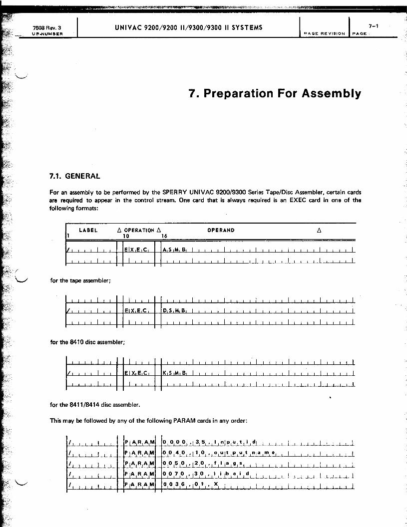
7508 Rev. 3 UNIVAC 9200/9200 11/9300/9300 II SYSTEMS PAGE REVISION PAGE
7. Preparation For Assembly
7.1. GENERAL
For an assembly to be performed by the SPERRY UNIVAC 9200/9300 Series Tape/Disc Assembler, certain cards are required to appear in the control stream. One card that is always required is an EXEC card in one of the following formats:
LABEL t::. OPERA liON t::. OPERAND t::. 1 10 16
V I I I Elx E C AS M B 11 I I I I I
I I I I I I I I I
for the tape assembler;
for the 8410 disc assembler;
for the 8411/8414 disc assembler.
This may be followed by any of the following PARAM cards in any order:
'..L. .. ..1 •.•. L I I I ,~~~~. !'~~.L.~L.3.l_~!_~_L!!.l?.L U It. i I dl .. L..l...-..L.L.L.LJ. I I I .1 .... .L ... L.Ll
, L ... 1...L 0 0L~~l!L~.L' I 0 I U It ! PL~.l.!~':'l.~L.L~LL~L_L .. .L~
, 0J.~ . .L5101'12101'lflllalglsL! I L..LLL.L-1_ .. ! I I LU , ,
7-1

7508 Rev. 3 UP·NUMBER
UNIVAC 9200/9200 11/9300/9300 II SYSTEMS PAGE REVISION PAGE
where:
inputid
x
Is groupnamel/groupname2/ .. ./modulename if the source program is the module named "module name" located within a specific -nest of groups on the input file; /modulename if the source program is the module named "module name" and selectivity based on the group structure is not required.
If source input is from tape, this parameter will cause the source input tape to stay open and allow stacked assemblies without rewinding the input tape; x is any nonblanks.
outputname
flags
libeid
Is the name of the output module as it will be entered in the E L T record.
Is a string of letters identifying the flags to be associated with the output module in its ELT record. If an asterisk (*) is used as the first character in the flags parameter, the option of rewinding logical unit 1 (rather than backspacing while using it as a scratch tape) is used. Stacked assemblies are still possible because the rewind option does not affect assembler use of the flags parameter in any way.
Is groupnamel/ .. ./groupnameN identifying the nest of groups in the macro library within which the library search is to be performed. The macro library is located on logical unit zero for the tape assembler. For the disc assembler, it is assumed to be located in SYSFI LE on logical unit zero, unless a PARAM 0131 card is used (7.2).
If the source program is in the control stream, PARAM cards must be followed immediately by a DATA card, which precedes the source program. This DATA control card must contain a T in column 16. In this case, the PARAM card defining inputid is omitted. If the PARAM card defining the name of the output module is omitted, the label of the START directive is taken as the output module name. The PARAM card defining the flags is omitted if no flags are to be associated with the output module. The PARAM card defining the limits of the library search is omitted if the entire macro library is searched. The name of the entire library is MACROLIB. If libeid is specified as the number 9, the assembler assumes that no calls requiring a library search are made in the program to be assembled.
Macro definitions may be submitted with source code and must precede the source code in the input deck. When the assembler detects a macro instruction, it searches the macro definitions submitted with the source code before it searches the library. Each macro definition in the library should be preceded immediately by an ELT demarcation record. Also, the very first line of each macro definition must be the PROC directive.
7.2. GENERAL PROCEDURES FOR DISC ASSEMBLERS
In addition to the preceding PARAM cards, other PARAM cards apply specifically to the disc assembter. General notes pertaining to these cards are:
• Logical unit numbers may be 1· or 2-digit hexadecimal numbers between 0 and 3F.
• Filenames must contain a maximum of eight characters.
• The output file and the scratch file must be unique; that is, neither file may contain the same filename and logical unit as any other file. Neither file may be SYSFI LE on logical unit zero.
This PARAM card is optional for 8410 disc units, and it is not used for 8411/8414 disc units. It is used to specify that all disc writes are to be verified (check read); if this PARAM card is omitted, no verification is made:
7-2

. r"
7508 Rev. 3 UNIVAC 920019200 11/930019300 II SYSTEMS UP.NUMBER PAGE REVISION PAGE
LABEL b. OPERA liON b. OPERAND b. 1 10 16
Ii i I I 1 PIA R,A M o 1 o 0 , ,0 1 , (1 I'll) , I I I
I I I L ,t ed_ t I , I
where:
N = Do not verify all disc writes.
C = Verify all disc writes.
This PARAM card is required because it defines the final output file:
where:
w
E
nn
Specifies that the file is not to be extended; i.e., the object module is to be written at the beginning of the file .
Specifies that the file contains information to be preserved and extended; i.e., the object module is to be written immediately after all other modules contained in this file.
Specifies the disc logical unit number in hexadecimal (0 through 3F).
NOTE:
Logical unit numbers may be a 1· or a 2-digit number (n or nn).
filename Specifies the name (maximum of eight characters) of this file.
This PARAM card is required and is used to define a file that is to be used as a scratch file if the source code is on cards, or is to be used as the input file if the source code is on disc. If this file is to be used as a scratc~ file, it may not be called SYSFI LE if it is mounted on logical unit zero.
7-3

~7508 Rev. 3 UNIVAC 9200/9200 11/9300/9300 II SYSTEMS 7-4
UPoNUMBER PA GE RE VISION PAGE
where:
nn Specifies the disc logical unit number in hexadecimal (0 through 3F).
NOTE:
Logical unit numbers may be a 1- or a 2-digit number (n or nn).
filename Specifies the name of this file.
This PARAM card is required and defines a scratch file:
LABEL /:). OPERA liON /:). OPERAND /:). 1 10 16
!! I PIA R ArM o 1 1 1 110 x If i I eln 1 a nil e 1 1 I
where:
nn Specifies the disc logical unit number in hexadecimal (0 through 3F).
NOTE:
Logical unit numbers may be a 7- or a 2-digit number (n or nn).
filename Specifies the name of file.
This PARAM card is optional and is used to define the file in which the macro instruction library is stored:
t-.L~.Lm I I , I
where:
nn Specifies the disc logical unit number in hexadecimal (0 through 3F).
NOTE:
Logical unit numbers may be a 7- or a 2-digit number (n or nn).
filename Specifies the name of the file in which the macro library is stored.
If no PARAM card is specified, there is a default of OO,SYSFllE.
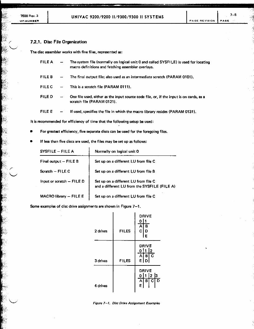
7508 Rev. 3 UNIVAC 9200/9200 11/9300/9300 II SYSTEMS UP.NUMBER PAGE REVISION PAGE
7.2.1. Disc File Organization
The disc assembler works with five files, represented as:
FILEA
FILE B
FILE C
FILE D
FILE E
The system file (normally on logical unit 0 and called SYSFI LE) is used for locating macro definitions and fetching assembler overlays.
The final output file; also used as an intermediate scratch (PARAM 0101).
This is a scratch file (PARAM 0111).
One file used, either as the input source code file, or, if the input is on cards, as a scratch file (PARAM 0121).
If used, specifies the file in which the macro library resides (PARAM 0131).
It is recommended for efficiency of time that the following setup be used:
• For greatest efficiency, five separate discs can be used for the foregoing files.
• If less than five discs are used, the files may be set up as follows:
SYSFI LE - FI LE A Normally on logical unit 0
Final output - FI LE B Set up on a different LU from file C
Scratch - FI LE C Set up on a different LU from file B
Input or scratch - FI LE D Set up on a different LU from file C and a different LU from the SYSFI LE (FI LE A)
MACRO library - FI LE E Set up on a different LU from file C
Some examples of disc drive assignments are shown in Figure 7-1.
2 drives FILES
3 drives FILES
4 drives
DRIVE
t1 A B C D
E
DRIVE
-mf12 ABC E D
DRIVE o 1 2 3 ABC D E
Figure 7-1. Disc Drive Assignment Examples
7-5

7508 Rev. 3 UP.NUMBER
UNIVAC 9200/9200 11/9300/9300 II SYSTEMS
7.2.2. Allocation of File Space for Disc
PAGE REVISION PAGE
A disc assembler user allocates space to his assembler files based on his needs and the type of assembly being run at any particular time. The sizes vary, depending on:
• the amount of space a user can afford at assembly time;
• the number of disc units available;
• whether the bulk of input is cards or disc; and
• whether macro are being submitted with source code.
The following discussion concerns the use of scratch files by the assembler. The available space in the final output file also is used as scratch space.
The assembler generates one internal item, and possibly more, for every source item processed. If the source item is a macro instruction, the item generation and required space will be expanded dynamically during generation of the instruction. Thus, since each case is different, the user can choose to allocate space based on each assembly or set up an all·inclusive allocation procedure to handle the largest assembly that he expects to turn out. In view of these possibilities the following guideline is proposed. It is intended as a guideline only and mayor may not satisfy the requirements of a particular installation.
It is assumed that the reader has a knowledge of the disc types and is aware of the requirements and procedures necessary for the operation of the VTOC for the 8410 disc subsystem (see the 9200/9300 systems 8410 disc subsystem utility programs manual, UP·7668) or the DASM for the 8411 or 8414 disc subsystems (see the 9200/9300 systems 8411/8414 disc subsystems utility programs manual, UP·7835).
A typical, large single·phase program is the first pass of the assembler. This module comprisec: approximately 3000 source items. The disc I/O handler generates two items per disc record. Inasmuch as each source item causes the assembler to turn out an internal item, 6000 items are to be processed for this assembly. In addition to the SYSFI LE, the assembler requires three work files to be used in the course of the assembly. Each file must contain two extents. The first extent consists of the file directory and the second consists of the file itself. Space allocation for the directory may be minimal and file allocation space is the most important consideration. The following space allocations were assigned in assembling the first pass of the assembler (with 3000 source records and no macro instructions) for each of the three files required:
• 8410 disc - 2 items per record, 100 sectors per track
3000 records = 3000 sectors = 30 tracks
For file directories, one track per file is allocated. Thirty tracks per file are allocated for file conte!1ts.
• 8411 disc - 2 items per record, 16 records per head
3000 records = 200 heads = 20 cylinders
One head per file is allocated for file directories, and 20 cylinders per file are allocated for file contents.
• 8414 disc - 2 items per record, 25 records per head
3000 records = 120 heads = 12 cylinders
One head per file is allocated for file directories. Twelve cylinders per file are allocated for file contents.
7-6

7508 Rev. 3 UP.NUMBER
NOTE:
UNIVAC 9200/9200 11/9300/9300 II SYSTEMS PAGE REVISION PAGE
Although tthe allocation of directory space during the assembly may be minimal, should the same file be used for storage of program libraries at other times, the size of the file directory should be adequate for file usage.
1.3. GENERAL PROCEDURES FOR TAPE ASSEMBLER
The tape assembler requires that a scratch tape be available on logical unit 3, that its input, if on tape, be on logical unit 2, and that a tape be available for writing on logical unit 1. This tape must be either a rewound scratch tape or must be in library tape format positioned immediately past the tape mark. This tape is used for scratch as well as to receive the final output. If the tape units are not assigned properly, SWAP cards to effect this assignment must precede the EXEC card.
1.3.1. Restart Procedure for Final Phase of Assembly
After the assembler has begun producing its printed output, two restart options are available: stop printing and repeat printing.
1.3.1.1. Stop Printing Option
If it is necessary to abort the production of printed output because of forms misalignment, torn ribbon, or other printer malfunctions, the stop printing option may be invoked by the operator by setting the DATA ENTRY switches to any value from X'01' to X'OF' and pressing the OP REO switch. The assembler ceases printing and, upon completion of writing the object module, restarts the printer listing from the beginning. It is suggested that, when the stop printing option is used, the printer be taken offline while the printer malfunction or forms alignment problem is being corrected.
1.3.1.2. Repeat Printing Option
If a second copy of the assembler printer listing is desired, the repeat printing option may be used by setting the DATA ENTRY switches to zero (X'O') and pressing the OP REO switch. Upon completion of the first listing, a second listing will be produced.
NOTES:
1. The foregoing operator requests may be made only after the assembler has begun printing. If made earlier, a 413F display occurs and the keyin is ignored.
2 An operator request with a value greater than X'OF' causes a 413F display, or is interpreted as a keyin to the operating system or to a symbiont.
3. The use of either option does not affect assembler production of a relocatable output module.
1.4. PRINTER OUTPUT
When a PRINT directive requests a listing of all source code lines, the output listing is:

UNIVAC 9200/9200 11/9300/9300 II SYSTEMS ER PAGE REVISION PAGE
Print Column Data
1-4 Sequence number of original input line; blank for macro-generated code
5 Blank
6-13 Error codes (eight allowable on anyone line)
14 Blank
15-18 Address
19,20 Blank
21-36 Object code (maximum of eight bytes or 16 digits printed)
37-40 Blank
41-120 Original source code line
The printer uses columns 6-13 to list error codes in the assembly listing. The codes used, and their meanihgs, are listed in Table 7-1.
Table 7-1. Printer Error Codes
Code Meaning
C Covering error
0 Duplicate label or reference to a duplicate label
E Expression too large, improper syntax, or keyword parameter specified in a macro instruction not defined in the proc line of the macro definition
F Upper main storage table full in pass 1 of assembler; too many DO statements to ptocess in available main storage
H Half-word boundary error
I Instruction error, invalid operation code
L Location counter value too large
M More DOs than ENDOs
0 ORG error, second definition of a label
P PROC error
R Relocation error, terms too many or improper
S Sequence error
T Truncation of oversized term
U Undefined label reference
X Continuation error or ESID table overflow
y Assembly input ends with common section or dummy control section
Z END card missing
1-8

7508 Rev. 3·· UNIVAC 9200/9200 11/9300/9300 II SYSTEMS PAGE REVISION PAGE
7.4.1. Assembler Listing Print Format
T he following are examples of the printer format for the page header and the last line of the assembler listing containing the total errors detected.
• Page Header For_mat
Print Column Data
1-29 UNIVAC 9300 {~~;~} ASSEMBLY OF
30-37 progname-name in label field of START card
38-39 blank
40-93 title - inserted by TITLE directive 54 characters long
94 blank
95-98 DATE
99 blank
100-101 characters 1 and 2 of supervisor date
102 /
103-104 characters 3 and 4 of supervisor date
105 /
106-107 characters 5 and 6 of supervisor date
108-109 blank
110-113 PAGE
114 blank
115-117 page number
118-120 blank
7-9

7508 Rev. 3 UP.NUMBER
UNIVAC 9200/9200 11/9300/9300 II SYSTEMS PAGE REVISION PA~
• Final Line of Assembler Listing
Print Column Data
1-39 same as PAGE HEADER format
40-49 blank
50-55 ERRORS
56 blank
57-61 error count - grand total of all errors in listing
62-70 blank
71-78 REVISION
79 blank
SO-81 revision number
82-94 blank
95-109 same as for PAGE HEADI:R format
110-120 blank
NOTE:
The last line of every assembly listing contains total errors (which can be greater in count than the total of all the flags because it is only possible to print eight flags per line) and the revision number of the SPERRY UNIVAC software. This revision number should be referred to when reporting problems with the software.
7.5. DISPLAYS FOR DISC ASSEMBLER AND INPUT/OUTPUT
Displays on the control console associated with the disc assembler are listed in Tables 7-2 and 7-3.
Table 7-2. Disc Assembler Displavs (Part 1 of 2)
Hexadecimal . Display Reason Action
30xO Logical unit x is down. Press START to cancel.
30u1 The source code element on physical unit u does not Press START to cancel. exist as specified in PARAM 0000 card, or physical unit u does not contain any part of the macro library, or source code is to be introduced from the control stream, but no source is present.

7508 Rev. 3 UP-NUMBER
UNIVAC 9200/9200 11/9300/9300 II SYSTEMS 7-11 PAGE REVISION PAGE
Table 7-2. Disc Assembler Displays (Part 2 of 2)
Hexadecimal Reason Action Display
The following stops are due to bad parameter cards.
3002 A W or an E was not specified on PARAM 0101. Press START to cancel.
3003 A file name was not supplied. Press START to cancel.
3004 A logical unit was not supplied or each character of the Press START to cancel. logical unit number was not in the range 0-9 or A-F.
3005 The filename (other than disc source input file or macro Press START to cancel. library) was SYSFILE and was said to be on logical unit o.
3006 More than one file was specified by the same name and Press START to cancel. logical unit number.
NOTE:
u = physical unit number.
Table 7-3. Disc Assembler Input/Output Displays
Hexadecimal Reason Action
Display
14u1 8410 - unrecoverable abnormal line indication received from Key nonzero into dispatcher location 4 to retry, or 8411/8414 - software error press START to cancel.
14u2 8410 - unrecoverable output bus check indication received Same as 14u1 from dispatcher 8411/8414 - hardware error
14u3 File cannot be opened because the VTOC header cannot Press START to cancel. be located or the file's format-1 label does not reside in area specified by the VTOC.
14u4 No find on search Same as 14u1
14u5 8410 - catastrophic failure indication received from dispatcher Same as 14u1
14u6 Expiration date does not meet requirements Press START to cancel.
14u7 8410 - non operational channel indication received from Same as 14u1 dispatcher
. 14u8 8410 - Invalid function indication received from dispatcher Same as 14u1
8411/8414 - wrong record length
14u9 File extent limit reached; READ or WRITE attempted that Press START to cancel. references a point beyond physical extent for th is file
14uB File directory filled to capacity Press START to cancel.
14uD Final output file described as to be extended (E) but next Key in nonzero to record pointers in format-1 label contain zeros locati on 4 to treat the
file as a new (W instead of E) file, or press START to cancel.
14uE File on unit u not a library file; i.e., it does not have Press START to cancel. two extents
14uF 8410 - an unload buffer command unsuccessfully issued Same as 14u1

7508 Rev. 3 UP-NUMBER
UNIVAC 9200/9200 11/9300/9300 II SYSTEMS 7-12 PAGE REVISION PAGE
7.6. DISPLAYS FOR TAPE INPUT/OUTPUT ROUTINE
Displays on the control console associated with the tape assembler are listed in Table 7-4.
Table 7-4. Tape Assembler Input/Output Displays
Hexadecimal Display
R_on Action
20u0 The end block was not found on physical unit Press START to try again. u. This display occurs with respect to logical Restart if unsuccessful. unit 1 when the assembler cannot find the END record on logical unit 1 preparatory to writing out its final output (Appendix cl.
2Ou1 The expiration date was not accepted Replace with correct tape and on physical unit u. press START to try again, or
key a nOnzero into location 4 and press START to cancel.
20\16 The end-of-physical-tape (while writing) or a Press START to cancel. tape mark (while reading) was detected on physical unit u.
2Ou6 A wrong-length block was read on Press START to cancel. physical unit u.
20uD Physical unit u is in a nonready condition. Correct the problem at physical unit u and press START to continue.
20uE The block searched for was not found on physical unit u. Ensure that physical unit contains the correct tape. Key one of the following into location 4 and press START:
o to try again, 1 to read forward, 2 to read backward.
Restart if unsuccessful.
30u1 The source code element on physical unit u does not exist Press START to cancel. as specified in PARAM 0000 card, or physical unit u does not contain any part of the macro library, or source code is to be introduced from the control stream, but no source is present. .
NOTE:
u = physical unit number

7508 Rev. 3 . UP.NUMBER
UNIVAC 9200/9200 11/9300/9300 II SYSTEMS 8-1 PAGE REVISION PAGE
8. Linker
8.1. GENERAL
Whether a program consists of one or more modules, the assembled module or modules must be combined into one executable program. This combining process is called linking and is performed by a utility program referred to as the linker.
8.2. LINKER COMMANDS
Linker command cards may contain information in columns 1 through 77. Logical unit numbers are expressed in hexadecimal. Spaces are required in all linker command formats before and after the command's opcode and following the last parameter specified in the operand field.
8.2.1. PRGM
The PRGM command instructs the linker to begin construction of a normal, executable program. It provides the name to be associated with the program and the address at which the program is to begin in storage.
The format of this command is:
LABEL D. OPERA liON D. OPERAND 10 16
The absolute origin address may be expressed as a number or as an asterisk. In the latter case, the program is assigned the same origin as was assigned to the linker doing the linking.
8.2.2. CHAI N
The CHAIN command instructs the linker to begin the construction of a program which is one of the links in a chained job, but is otherwise a normal executable program.
The format of this command is:

7508 Rev. 3 UNIVAC 9200/9200 11/9300/9300 II SYSTEMS 8-~ UP-NUMBER PAGE REVISION PAIOE
8.2.2.1. Fetching
To get the next chained program, the program's name must be placed in locations X'136' - X'13D' by the previous program and a FETCH be performed or another I EXEC statement may be given to job control; e.g.,
LABEL OOPERATlON6 OPERAND 6 1 10 16
~L~·~EIC , __ ~JR I Gfil i 1 I I I I I I I I 1 L I I I ! I .... _.LI ! I I .L .... J I I I L~~-L~R ! 1 I 1 ..1
~. !E,~ EL~LL._ £l~_L~LI_J!'I E 01 L I I I I 1 I __ ~_L._.L.~_L. __ L. I I I 1 •• __ L_.l.~ .- r-~: . .L._..LJ.- I.._L
I E X EIC .1 CJH .LA .LltN E 01...2 1 I I I I I I I I I I I I I I I_L-1~...l I I I I I j I I or
I ! -L-l ...... ! I I I I 1 I I I Ll I I j i .1 I I I I~I I I I 1-1-M V CI Xl' 1 3 6
, ( 8 ) "Ic L 8, ,
CIH A I N EID 1 , I I I ,
~~ TIC N C,H A I N .. .i._.
E 0 1 • I' IFIOIRIW,AIRIDI I I I ! I I 1_ ... 1... I I I I L I I I I ..Ll-L
Each link of a chain must begin with a CHAI N command, and the links must be described to the linker in succession. The linker allocates to each link the maximum storage required by anyone link and ensures that COMMON is assigned the same address in each link. A maximum of 10 consecutive chained programs is permitted. All programs consisting of a common section are given the same address when the chained programs are linked.
8.2.3. SYMB
The SYMB command instructs the linker to begin the construction of a symbiont. No overlays are allowed within a symbiont.
The format of the command is:
SYMB
In the preceding commands (PRGM, CHAIN, and SYMB), the flags field is a character string. Permissible characters in the string are the 26 alphabetics and the multipunch, which, when translated to EBCDIC, yields the EBCDIC byte 11100001. (In Hollerith card code, this would be an 11-0-9-1 punch.)
The PRGM, CHAIN, and SYMB commands also produce on the output file an ELT record preceding the module to be constructed by the linker. The program or symbiont name becomes the module name (preceded by the names of the groups in which the module is contained). The flags determine the bits of the flag field (columns 6-9) of the ELT record in the following format:
*DHLPSWzAEIMQTXzBFJNRUYzCGKOxVZz

7508 Rev. 3 UNIVAC 9200/9200 1119300/9300 II SYSTEMS UP·NUMBER PAGE REVISION PAGE
Vllhere:
* Is always 1.
x Represents the EBCDIC byte 11100001.
z Is always zero.
Comments, beginning with the first nonblank column after the flags field, from the PRGM, CHAIN, or SYMB command are placed in bytes 60-SO of the output ELT record.
The first command given to the linker must be the PRGM, the CHAIN, or the SYMB command; otherwise the linker does not allow further processing and cancels.
8.2.4. UNITS
The UNITS command, if present, must follow immediately a PRGM, CHAIN, SYMB, or another UNITS command. It instructs the linker to construct a list of logical unit numbers for insertion in the phase record of the program to be created.
The format of this command is:
I' 11 OPERATION 11
10 16 LABEL OPERAND
where:
Each xx is a 2-digit hexadecimal number, the logical unit number of a unit required by the program.
8.2.5. INCLUDE
The INCLUDE command instructs the linker to include a specified module or specified portions of a module in the current phase. The format of this command is:
for tape linker:
for disc linker:
L
8-3
.- ~

7508 Rev. 3 UNIVAC 9200/9200 11/9300/9300 II SYSTEMS UP.NUMBER PAGE REVISION PAGE
If modulename is omitted (marked by a leading commal. the module is in the control stream immediately following the INCLUDE command; otherwise, the module is found on the indicated unit or filename. The logical unit number 'J is expressed as one or two hexadecimal digits. If the logical unit number is omitted, the same unit is used as for the last INCLUDE with the indicated modulename. The initial value is 2 for the tape linker; for the disc linker, it is the logical unit number specified for the input file on the CTL card. For the disc linker, if the filename is omitted, the same filename is used as for the last INCLUDE with a module name indicated. The initial filename is the filename specified on the CTL card for the input file. If the tape linker is used and the logical unit number is specified, the tape is rewound before the search for the module begins. If the logical unit number is not specified, the tape is not rewound.
Modulename may consist of a single name preceded by a slash, in which case the indicated logical unit and/or file is read until a module with the specified name is found. This module then will be included; otherwise, the modulename must include the name of all the groups within which the element is contained, from outermost to innermost. Thus, if module MODLA is group GRP2, which is in group GRP1, the modulename is written as:
LABEL b. OPERA 110104 b. OPERAND 10 16
If an INCLUDE command specifies an LU#, the tape linker rewinds the specified tape before beginning the search for the module.
The last parameter, if included, is a list of one or more control section names with the list enclosed in parentheses. Only the named control sections are included as a result of the INCLUDE command. If however, a module contains a common section, the common section is included when any control section of the module is included. A control section may be included in more than one phase. In such a case, all references to that control section are handled as follows:
• If the reference is in a phase in which the control section is included, the reference is linked to the copy of the control section in the phase.
• If the reference is in a phase in which the control section is not included, the reference is linked to the first copy of the control section included in the program.
• The common section is located immediately above the highest location of any other section coding or job control coding.
8.2.5.1. Sectioning (CSECT, OSECT)
A label in a CSECT section should be referenced only within its own section; otherwise, an ESID UNO error occurs when linking that particular section. If necessary, to reference a label in a section other than the section needed, the programmer must include both sections when linking a particular phase to avoid ESID UNO errors.
All ESIDs will be resolved if the following procedure is used:
~' .-:.:
-!

f
~.
. \ ...... /
7508 Rev. 3 UP.NUM8ER
Example (Assembly):
LABEL 1
TIS T I
!
B GIN I I
I
COIN I
CS2 I
I
T AGf I I
-'--'- 1 , I
I I
T-,-S-,-T • I
I
GO, I
.1 I
Example (Linker):
P,R,G,~ I
IN, C L U,D, E
I
I I I I I I
8.2.6. PHASE
UNIVAC 9200/9200 11/9300/9300 II SYSTEMS
OOPERATlON~ OPERAND 10 16
SIT A R,T 0, ' I I ! I
UIS IN G * , 0 L ! ! , ! I I ! I ! I I
MIS G 1 I I I I
BIC 1 5, T AIG , I I
DIC X ' 1 1 " I , I
CIS ECT I I I
MIV C BGN+71' 0 1 I I
CIL I CON, XI' 1 2 ,
I I I
BI C 1
31
, B G NIl i I I I
BIC 1 5 , T AIG I , CIS E
1C
1T
i J ..l I J DIC- .. X ' 00 ' I I , I
Dl c X' 00 ' i I 1 I I 1 I 1 1 1 1 1 I , 1 I
EIN ° BGN I I I I I I I I I I
TIE S T • I I I ,
'IT ST, 00, (I T,S,T 1, IC,SIZ \' I I ! , i I
I I I I , I , , I
PAGE REVISION PAGE
~
, I , , I
I ! , I I I I I I I I ! I I I
I I I
I , I I , , I
I L I
, I ! I
' I I I
I I Jl I [ I
I I I I '
I -'- .l 'J , I .LL.
I , I I
I 1 I-L I I 1 I I , 1 I I 1 I ,
I I I I I , I i I I i ; I i
, I , I I
, I , I I I I I I I , I I---LL ill ! , I I ,
The PHASE command instructs the linker to begin construction of a new phase and indicates how its origin is to be determined.
The format of this command is:
where:
phase name Represents the name of the phase to be constructed and origin may be one of the following:
blank Indicates the new phase will immediately follow the phase just completed.
8-5

1508 Rev. 3 UP.NUMBER
UNIVAC 920019200 11/930019300 II SYSTEMS 84 PAGE REvISION PAOli:
nnnn Is a decimal number or a hexadecimal number of the form X'nnnn' and specifies the origin of the phase.
symbol Is a previously defined symbol (an entry point of one of the modules already included). The value assigned to this symbol is assigned as the origin of the phase.
symbol±n Is symbol and n as defined previously. The value assigned to the symbol is modified as indicated and the result assigned as the origin of the phase.
(phasename list) Is a list of one or more phase names separated by commas if more than one name is listed. The list is enclosed in parentheses. The phase follows the phase named in the list with whose highest allocated address is the greatest. The address allocated is a multiple of two.
A phase is terminated by the next PRGM, CHAIN, SYMB, PHASE, or END command. The entry point for a phase is the address from the first transfer card for a module in the phase. In a phase containing selected control sections of a module, the transfer card address is accepted only if its address is external to that module or contained in a conttol section included in the phase. In the absence of a transfer card with an acceptable address, the first address of the phase is used as an entry point. The maximum allowable number of phases is 20 to 30, depending upon the number of characters in the phase names.
8.2.7. MOD
The MOD (modular set) command instructs the linker to set the location counter to the value calculated from the operand specifications.
The format for this command is:
LABEL /:;,. OPERA liON /:;,. OPERAND /:;,. 1 10 16
iMIOIDI 101 b I 1 1 I I I I I I I I I
I I I I I I. I I 1 1 I 1 1 1 .1 I I
\t\tlere:
a Must be a decimal expression with a value that is the result of 2 raised to a power.
b May be omitted, or it may be a decimal expression.
The location counter is set to the next number with the value of b, plus a multiple of a which is greater than, or equal to, the present value of the location counter.
Examples:
II II

7508 Rev. 3 UP-NUMBER
UNIVAC 9200/9200 11/9300/9300 II SYSTEMS 8-7 PAGE REVISION PAGE
If the present value of the location counter 4024, the value is not modified. If the current value is 4025, it is modified to 4032.
LA8EL 6. OPERATION 6. OPERAND 6. 1 10 16
M,OID 18 3 I I I I I I I
I I I I I I I I I I I I
If the current value of the location counter is 4028, its value is modified to 4035.
8.2.8. LlBE
The LISE command instructs the linker to search for modules externally referenced within the modules being linked and not included via INCLUDE statements. The fotmat of this command is:
for the tape linker:
for the disc linker:
The search is limited to modules within the group named on the indicated logical unit or file. If the group to be searched is in another group, groupname must so indicate. Thus, if all modules in GRP3 are to be searched and GRP3 is in GRP2, which is contained in GRP1, groupname would be written:
GRP1/GRP2/GRP3
If LU# is omitted, the search is performed on the logical unit most recently named in a LISE statement. Initially, the search is set to operate on logical unit 0 in group RLOCATSL.
For the disc linker, if filename is omitted, the filename most recently named in a LISE statement is used. Initially, filename SYSFI LE is used.
If no search is needed, the format is:
I :L:':8:": ~:olt: : : : II : : : : : : : : : : : : : : : : : : : : : : : : : : : : : :

7608 Rev. 3 UNIVAC 9200/9200 11/9300/9300 II SYSTEMS UP.NUMBER PA GE RE VISION PAGE
A LISE command is effective for the program in which it appears and all programs until the next LISE or END card. If several LISE cards appear between two PRGM cards, only the last is effective. Routines included by the automatic search feature are included in the first phase of that program. They are not overlaid by any phase of the program because they are assigned load addresses beginning immediately after the highest address occupied by any phase of the program.
A module is included automatically only if no flags are associated with it or if all its flags also appear in the PRGM, CHAIN, or SYMS command for the program being linked.
8.2.9. EaU
The EaU command to the linker defines values not otherwise supplied in the normal linking process.
The format of this command is:
LABEL 6. OPERA 1101'4 6. OPERAND 6. 1 10 16
ISIV m bioI! IE QUI e x IP r e S silo I n I I I I I
I I I I I I I I I I I I I I I
where:
symbol Represents the name of the symbol, the value by which it is to be defined.
expression Is any sum or difference of decimal values, hexadecimal values of the form X'nnnn', and previously defined symbols. A previously defined symbol is one that is an entry point of a module previously named on an INCLUDe card, or a symbol already defined by an EaU card.
8.2.10. END
The END card (/* in columns 1 and 2) terminates the linker operation. To rewind logical unit 1 at the end of the tape linking, place a non blank in column 11 of the card.
8.2.11. SELECT
The SELECT command causes the linker to copy a module from an input file (or tape) to the final output file (or tape).
The format of this command is:
for the tape linker:
8-8

7508 Rev. 3 UPoNUM&ER
UNIVAC 9200/9200 11/9300/9300 II SYSTEMS PAGE REVISION PAGE
for the disc linker:
LABEL b, OPERA liON b, OPERAND 10 16
where:
modulename
LU#
Is the modulename or the groupname and modulename in the input EL T record of the module to be selected. The module may be source, relocatable, or object code. It must begin with an E L T record and be followed by a BOG, EOG, EL T, or END record.
Is the logical unit number of the tape or disc containing the input module to be selected.
filename Is the name of the file containing the input module to be selected.
If no logical unit number is specified, the last logical unit number specified in a SELECT or INCLUDE command is used; if no previous logical unit number (and filename, for disc) was specified previously in a SELECT or INCLUDE command, the search is made on the initial logical unit number/filename. The initial logical unit number for the tape linker is 2; for the disc linker the initial logical unit number and filename are specified in the CTL card. The search for the named module begins in a forward direction from the current position, if tape.
If a logical unit number or filename is specified in a SELECT command, that designation remains selected until changed by a subsequent SELECT or INCLUDE command. The tape linker rewinds the tape on the specified logical unit before beginning the search for the named module.
The SELECT command should be placed after the last INCLUDE command of a program or symbiont or after the last INCLUDE command of the last program of a chain of programs. SELECT terminates a chain, but another chain may follow.
When the linker detects a SELECT command, it treats the command as an indication that all commands for a program, a symbiont, or a chain of programs under construction have been submitted. After completion of the program construction, the linker locates the named module on the specified logical unit and copies the module on the output file. The copied module is preceded by an EL T record on the output file.
8.2.12. HALT
The HALT command permits the operator to take appropriate action during a link; e.g., changing input disc packs.
The format of this command is:
8-9

7508 Rev. 3 UNIVAC 9200/9200 11/9300/9300 II SYSTEMS UP.NUMBER PAGE REVISION PAGE
VIkIere:
nnnn Is any allowable hexadecimal character, 0 through F. The value is right·justified in the light display; that is, HALT 1 appears as 0001.
8.2.13. SPACE
The SPACE command controls the spacing of the listing by specifying SPACE 1 or SPACE 2. If an error is made in the number of spaces designated, the default of 1 space occurs.
This option is not available in the tape linker. which always produces a single-spaced listing.
The format of this command is:
LABEL /). OPERA liON /). OPERAND /). 1 10 16
UN U SIEIDI SIP .Ale E n I I I I I _L I I
I I I I I I J J I
where:
n Is the number 1 or the number 2.
8.3. LINKER OPERATING INFORMATION
The procedures and displays used to operate the linker, the error messages produced on the printer, and an illustration of a sample deck are described in the following paragraphs.
8.3.1. Disc Linker Procedures
To execute the disc linker, the following control stream must be submitted:
I EXEC I DATA
CTl
1*
DL11 (DlOOfor 8410 linker) C (See 8.3.1.1 for parameters)
linker commands
Disc packs containing files required by the linker must be mounted before executing the linker.
8-10
--a.

7508 Rev. 3 UNIVAC 9200/9200 11/9300/9300 II SYSTEMS 8-11
UP.NUMBER PAGE REVISION PAGE
NOTES:
1. If using 8410 disc drives, remove the file protect from disc on logical unit number 0 as DLOO uses the Fastband for scratch space.
2. File protect on logical unit number 0 is allovved on the 8411/8414 disc subsystem unless the scratch or final output file is located on unit O.
3. Do not change output discs during linking on the 8411/8414 disc subsystems. With a careful choice of areas it is possible to change input disc packs as many times as required by use of the HALT command and pack substitution.
S.3.1.1. CTL Card
Only one CTL card may be specified for the disc linker. The CTL card is mandatory and must follow the / DATA C card in the control stream.
The format of the card is:
LABEL llOPERATIONll OPERAND 10 16
where:
c Output is to use check write.
N Output is to use normal write, or unit is 8411/8414 disc drive.
w Indicates final output file; output to start with beginning of file.
E
Indicates final output file; output to be written as an extension of the information already in the file.
R Indicates first input file.
s Indicates scratch file; this must be a library type file though the directory need only hold one record.
xx Is a logical unit number; one or two hexadecimal digits.
name Indicates filename.
No default option is permitted. Absolute control over the location of the linker output module is imperative. The control card is printed. Each file description must state all three designators; i.e., type of file, unit, and filename. All files used by the linker must be in library format; i.e., one directory extent and one data extent.

7508Aev.3 UNIVAC 9200/9200 1\/9300/9300 \I SYSTEMS U,P-NU.MBER
8.3.2. Tape Linker Procedures
To execute the tape linker, the following control stream must be sumitted:
/EXECTLOO /DATAC
. (linker commands)
1*
PA GE RE VISION PAGE
Appropriate tapes, as required by the linker, including the output tape on logical unit 1 and the scratch tape on logical unit 3, must be mounted before executing the linker.
8.4. PRINTER ERROR MESSAGES
The linker routine notifies the programmer of problem program errors. The messages that can be made by printer listing during a linker run are listed in Table 8-1.
The revision number of the SPERRY UNIVAC software is printed on the last line of output. The revision number must be referenced when reporting software problems.
8.4.1. User Program Sense Indicator (UPSI) Byte Setting
If an error is detected, during a link, the single bit of the UPSI byte (location X'117'), shown as a 1 (00001000), is set to 1. This permits detection of errors by a subsequent program in the job stream or by a / SKIP job control card, providing a / JOB control stream command does not intervene. The linker never resets this bit to zero; therefore, any error in a series of links may be tested for after the last link.
8.4.2. Total Error Count
A total error count is printed in the last line of the linker listing.
8.4.3. Suppression of Second Pass Printing
To cause the suppression of all printer output during the second pass of the linker (except page heading, error messages, and the total error count), place the following parameter card after the I EXEC card and in front of the I DATA card.
LABEL OOPERA TlONll 1 10 16
OPERAND
~\ /
8-12

7508 Rev. 3 UP.NUMBER
UNIVAC 9200/9200 11/9300/9300 II SYSTEMS 8-13 PAGE REVISION PAGE
Table 8-1. Linker Printed Error Messages
Message Meaning
NAME UNO Name is undefined.
PH NM UN Phase name is undefined.
HEXNG Hexadecimal value is not good.
ESID UNO Undefined ESID appears in relocatability data (RLD) on transfer card or text card.
NAME BLK Name is blank.
OVERFLOW Overflow of table area (any table),
SYMB NA Symbiont is not allowed.
COMMA NA Comma is not allowed.
EXPRESHN Expression is in error.
OPRND NG Operand is not good.
)MISSING Right parenthesis is missing.
BAD UNIT Physical unit is not allocated; logical unit is 1,3, or greater than 7 for the tape linker, or is not in the system configuration.
HOLE CNT The sum of the bytes from columns B-72 of an input record did not agree with the checksum in column 7.
ABS MODL Absolute module is not allowed.
ALRINCL Module already is included.
CARDCNT Card count error is in module.
UNEQU Unequal value is on defined name.
COL 1? Column 1 error is on EQU.
NO GROUP Group specified on L1BE card is not in this file.
NO ELT EL T record specified on INCLUDE card is not in the file.
8.5. DISPLAYS FOR DISC LINKER
The displays for the disc linker routine are listed in Table 8-2.
Displays 14u1 through 14uF for the disc linker are the same as displays 14u1 through 14uF, as shown in Table 7-3.

7508 Rev. 3 UNIVAC 9200/9200 11/9300/9300 II SYSTEMS UP.NUMBER PAGE REVISION PAGE
Table 8-2. Disc Linker Displays
Hexadecimal Reason Action
Display
1F03 Wrong input image was read Press START to ignore the image.
1F04 Card out of sequence Press START to ignore the card.
1F05 Card hole count error If the display occurs while reading an object module from the control stream, the card on which the error occurred is the second card from the top in the output stacker.
To reread the error card, place it and all following cards (including the card in the wait station) in the input hopper, feed a card, and press START.
If the display occurs while reading a tape or disc object module, pressing START may result in the generation of an invalid object module by the linker.
1FFF Unrecoverable condition of missing or Press START to cancel. invalid phase name, invalid device, overflow message, or a PRGM, CHAIN, or PHASE command card is preceded by a command card which is not in proper sequence.
4102 The first card read was a CTL card Reinitialize the linker input deck with a valid containing invalid specifications, CTL card as the first card in the reader, feed or was not a CTL card. a card, and press START.
8.6. DISPLAYS FOR TAPE LINKER
The displays for the tape linker are listed in Table 8-3. Displays 2OuO through 20uE for the tape linker are the same as displays 20uO through 20uE as shown in Table 7-4.
Table 8-3. Tape Linker Displays
HallClecimal Display
Reason Action
1554 Cannot read from logical unit 3 to load Press START to cancel. pass 1.
1555 Cannot read from logical unit 1 to load Press START to cancel. pass 2.
1F03 Wrong input image was read. Press START to ignore the image.
1F04 Card out of sequence Press START to ignore the card.
1F05 Hole count error See action for disc linker display 1 F05.
1FFF Unrecoverable condition of missing or Press START to cancel. invalid phase name, invalid cI..-vice, overflow message, or a preceding 1555 display.
8-1.4
-;..

7508 Rev. 3 UP.NUMBER
UNIVAC 9200/9200 11/9300/9300 II SYSTEMS A-1 PAGE REVISION PAGE
Appendix A. Tape Language Processor Conventions
Certain processor conventions are used consistently by the language processors such as the assembler, the linker, the FORTRAN compiler, and the COBOL compiler. The following describe these conventions.
Each processor produces its output on logical unit 1. The system is assumed to be on logical unit O. Each processor, at the beginning of its operation, must test to see if the tape on logical unit 1 is at load point. If the tape is not at load point, no action is taken. If it is, the processor must read past any volume headers. The processor must then check the HDR1 record expiration date against the date stored in the supervisor. If the HDR1 date is less than or equal to the date stored in the supervisor, or if there is no HDR 1 label, the processor rewinds the tape.
A processor using logical unit 1 as a scratch must record an END record indicating block number 1 and zero group levels if that tape is at load point. Following this, a tape mark is recorded on tape. If the tape is not at load point, it is assumed that it is positioned immediately past the tape mark that follows an END record. This tape then may be used by the processor for scratch. When the processor is ready to write its output, it must back space past the tape mark. It must then read the END record backward to pick up the block count and group names it will use in producing its output. It then overwrites the END record in producing its first block of output with the block number that had been in the end record.
If a processor does not use logical unit 1 for scratch, it may postpone its load point test until it is ready to write its output. In this case, it would not need to write the END record and tape mark, and immediately backspace and overwrite them.
When a processor that has found logical unit 1 at load point is ready to write on logical unit 1, it must first read past any volume headers then write an HDR1 label with an expiration date of zeros before producing any output of its own.
When the processor finishes producing its output, it writes an appropriate END record and tape mark on logical unit 1 following the output. The tape is not rewound.
If a scratch tape is at load point, a processor reads past any volume headers. It checks the HDR1 record expiration date against the date stored in the supervisor. If the HDR1 date is larger, it rewinds the tape with interlock and gives a standard error display. It tries again if START is pressed. If the HDR1 date is less than or equal to the date stored in the supervisor, it writes a tape mark and the remainder of tape is available for scratch. If there is no HDR 1 label, it writes one with an expiration date of zeros, followed by a tape mark. The rest of the tape is then available.


7508 Rev. 3 UP.NUMBER
UNIVAC 9200/9200 11/9300/9300 II SYSTEMS B-1 PAGE REVISION PAGE
Appendix B. Standard Card, EBCDIC,
and Printer Graphic Codes
SPERRY UNIVAC 9200/9300 Series software is designed to use the standard card, internal, and printer graphic codes as shown in Table B-1. These codes are based on a byte divided into a zone and digit portion, each containing four bits, as:
zone digit
0123 I 4567 bits
In Table B-1, the zone and digit bits of the byte are the matrices; for each position the Hollerith code and the printer graphic, if any, are given.
Table 8-1. Standard Codes (Part 1 of 4)
(Two Most Significant Bits of Zona 00)
Two L_t Significant Bits of Zona Digit
00 01 10 11
0000 12·Q.9·8-1 12-11-9-8-1 11·Q.9-8·1 12·11·0·9·8·1
0001 12·9·1 11·9-1 Q.9-1 9-1
0010 12·9·2 11·9·2 Q.9·2 9-2
0011 12·9·3 11·9·3 Q.9-3 9-3
0100 12·94 11-94 Q.94 9-4
0101 12·9·5 11·9·5 Q.9·5 9-5
0110 12·9-6 11-9-6 Q.9-6 9-6
0111 12-9·7 11·9-7 Q.9·7 9-7
1000 12·9·8 11·9·8 Q.9-8 9-8
1001 12·9·8·1 11·9·8-1 Q.9-8-1 9-8·1
1010 12-9·8·2 11·9-8·2 Q.9·8·2 9-8-2
1011 12·9·8·3 11·9-8-3 Q.9-8-3 9-8-3
1100 12-9·8·4 11·9·8·4 Q.9·84 9·8·4
1101 12·9·8·5 11-9-8·5 Q.9·8·5 9·8-5
1110 12·9·8-6 11·9·8-6 Q.9-8-6 9-8-6
1111 12·9·8·7 11·9·8·7 Q.9-8-7 9-8-7

7508 Rev. 3 Up·NUMBER
UNIVAC 9200/9200 11/9300/9300 II SYSTEMS
Table 8-1. Standard Codes (Part 2 of 4)
(Two Most Significant Bits of Zone 01 )
Two Least Significant Bits of Zone Digit
00 01 10
0000 12 11 f::, & -
12·0·9·1 12·11·9-1 ()'1 0001
0010 12·0·9·2 12·11·9·2 11-0·9·2
0011 12·0-9-3 12·11·9·3 11·0-9-3
0100 12·0-9-4 12·11·9-4 11-0-9-4
0101 12·0·9·5 12·11·9·5 11·0-9-5
0110 12·0·9-6 12·11·9-6 11·0-9-6
0111 12·0-9·7 12·11·9·7 11·()'9-7
1000 12·0-9-8 12·11·9·8 11·0-9-8
1001 12·8·1 11·8-1 ()'8-1
1010 12·8·2 11·8-2 12·11 e !
1011 12·8-3 11·8·3 ()'8-3 $ .
1100 12·8-4 11·8-4 ()'8-4
< * %
1101 12·8-5 11·8·5 ()'8-5 ( ) -
1110 12·8-6 11-8-6 ()'8-6
+ ; > 1111 12·8-7 11·8-7 ()'8-7
I -, ?
B-2 PAGE REVISION PAGE
11
12·11·0
12·11·0-9-1
12·11·()'9-2
12·11·0·9-3
12·11·0·9-4
1 2·11·()'9-5
1 2·11·()'9-6
12·11·0-9-7
12·11·0·9-8
8-1
8-2 :
8-3 #
8-4 @
8-5 . 8-6 =
8-7 ..

r o
7508 Rev. 3 UP-NUMBER
Digit
0000
0001
0010
0011
0100
0101
0110
0111
1000
1001
1010
1011
1100
1101
1110
1111
UNIVAC 9200/9200 11/9300/9300 II SYSTEMS
Table 8-1. Standard Codes (Part 3 of 4)
(Two Most Significant Bits of Zone 101
Two Least Significant Bits of Zone
00 01 10
12-0-8-1 12-11-8-1 11-0-8-1
12-0-1 12-11-1 11-0-1
12-0-2 12-11-2 11-0-2
12-0-3 12-11-3 11-0·3
12-0-4 12-11-4 11-0-4
12-0-5 12-11-5 11-0-5
12-0-6 12-11-6 11-0-6
12-0-7 12-11-7 11-0-7
12-0-8 12-11-8 11-0-8
12-0-9 12-11-9 11-0-9
12-0-8-2 12-11-8-2 11-0-8-2
12-0-8-3 12-11-8-3 11-0-8-3
12-0-8-4 12-11-8-4 11-0-8-4
12-0-8-5 12-11-8-5 11-0-8-5
12-0-8-6 12-11-8-6 11-0-8-6
12-0-8-7 12-11-8-7 11-0-8-7
8-3 PAGE REVISION PAGE
11
12-11-0-8-1
12-11-0-1
12-11-0-2
12-11-0-3
12-11-0-4
12-11-0-5
12-11-0-6
12-11-0-7
12-11-0-8
12-11-0-9
12-11-0-8-2
12-11-0-8-3
12-11-0-8-4
12-11-0-8-5
12-11-0-8-6
12-11-0-8-7
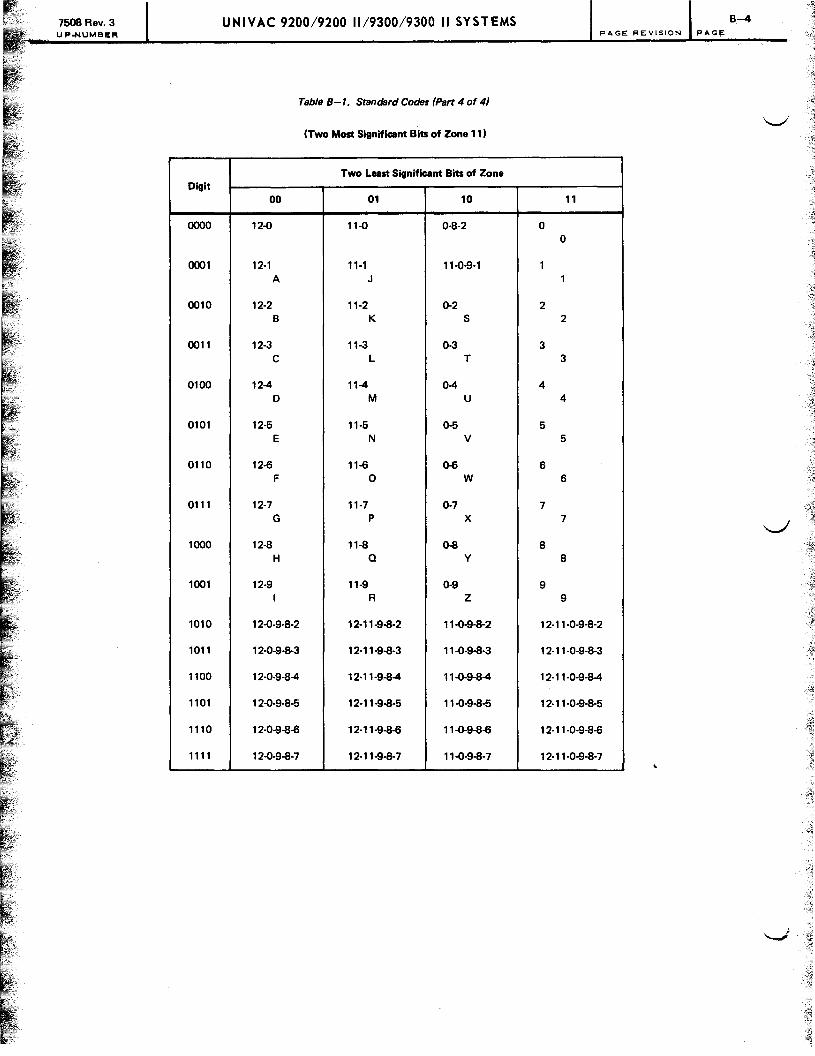
7508 Rev. 3 UPoNUMBER
Digit
0000
0001
0010
0011
0100
0101
0110
0111
1000
1001
1010
1011
1100
1101
1110
1111
UNIVAC 9200/9200 11/9300/9300 II SYSTEMS B-4 PAGE REVISION PAGE
Table 8-1. Standard Codes (Part 4 of 4)
(Two Most Significant Bits of Zone 11)
Two Lust Significant Bits of Zone
00 01 10 11
12-0 11-0 0-8-2 0 0
12-1 11-1 11-0-9-1 1 A J 1
12-2 11-2 0-2 2 B K S 2
12-3 11-3 0-3 3 C L T 3
12-4 11-4 0-4 4 0 M U 4
12-5 11-5 0-5 5 E N V 5
12-6 11-6 0-6 6 F 0 W 6
12-7 11-7 0-7 7 G P X 7
12-8 11-8 0-8 8 H a y 8
12-9 11-9 0-9 9 I R Z 9
12-0-9-8-2 12-11-9-8-2 11-0-9-8-2 12-11-0-9-8-2
12-0-9-8-3 12-11-9-8-3 11-0-9-8-3 1 2-11-0-9-8-3
12-0-9-8-4 12-11-9-8-4 11-0-9-8-4 1 2-11-0-9-8-4
12-0-9-8-5 12-11-9-8-5 11-0-9-8-5 12-11-0-9-8-5
12-0-9-8-6 1 2-11-9-8-6 11-0-9-8-6 1 2-11-0-9-8-6
12-0-9-8-7 12-11-9-8-7 11-0-9-8-7 1 2-11-0-9-8-7

Comments concerning this manual may be made in the space provided below. Please fill in the requested information.
System: ______ ~----------------------------------------------Manual Title: ___________________________________________ _
UP No: ______ _ Revision No: _______ _ Update: _______ _
NameofUser: ____________________________________________________ _
Add~ssofUser: ________________________________________________ _
Comments:

I I I 1 I I I I I '--./. I I I I I I 1 I I I I I -----------------------------------------------1
P.O. BOX 500 BLUE BELL, PA.
19422 SYSTEMS PUBLICATIONS DEPT.
~-------------------------------------------------
I 1 I I I I l I I I J 10 t~
I-J I I I I I I I I I