Embed Size (px)
Citation preview
920 IEEE TRANSACTIONS ON BIOMEDICAL CIRCUITS AND SYSTEMS, VOL. 11, NO. 4, AUGUST 2017
Compact, Highly Efficient, and Fully FlexibleCircularly Polarized Antenna Enabled by SilverNanowires for Wireless Body-Area Networks
Zhi Hao Jiang, Member, IEEE, Zheng Cui, Taiwei Yue, Student Member, IEEE,Yong Zhu, and Douglas H. Werner, Fellow, IEEE
Abstract—A compact and flexible circularly polarized (CP)wearable antenna is introduced for wireless body-area networksystems at the 2.4 GHz industrial, scientific, and medical (ISM)band, which is implemented by employing a low-loss compositeof polydimethylsiloxane (PDMS) and silver nanowires (AgNWs).The circularly polarized radiation is enabled by placing a planarlinearly polarized loop monopole above a finite anisotropic artifi-cial ground plane. By truncating the anisotropic artificial groundplane to contain only 2 by 2 unit cells, an integrated antenna with acompact form factor of 0.41λ0 × 0.41λ0 × 0.045λ0 is obtained, allwhile possessing an improved angular coverage of CP radiation.A flexible prototype was fabricated and characterized, experimen-tally achieving S11 <− 15 dB, an axial ratio of less than 3 dB,a gain of around 5.2 dBi, and a wide CP angular coverage in thetargeted ISM band. Furthermore, this antenna is compared to aconventional CP patch antenna of the same physical size, which isalso comprised of the same PDMS and AgNW composite. The re-sults of this comparison reveal that the proposed antenna has muchmore stable performance under bending and human body loading,as well as a lower specific absorption rate. In all, the demonstratedwearable antenna offers a compact, flexible, and robust solutionwhich makes it a strong candidate for future integration into body-area networks that require efficient off-body communications.
Index Terms—Off-body communications, polydimethylsiloxane(PDMS), silver nanowires (AgNWs), wearable antenna, wirelessbody-area networks.
I. INTRODUCTION
A S THE technologies of wireless body-area networks(WBANs) and wearable electronics devices continue
to develop at a rapid pace, the demand for compact
Manuscript received December 21, 2016; revised February 13, 2017; acceptedFebruary 15, 2017. Date of publication May 23, 2017; date of current versionJuly 26, 2017. This work was supported by the National Science FoundationASSIST Nanosystems ERC under Award Number EEC-1160483. This paperwas recommended by Associate Editor P. Mercier.
Z. H. Jiang was with the Electrical Engineering Department, The Pennsylva-nia State University, University Park, PA 16802 USA. He is now with the StateKey Laboratory of Millimeter Waves, Southeast University, Nanjing 210096,China (e-mail: [email protected]).
Z. Cui and Y. Zhu are with the Department of Mechanical and AerospaceEngineering, North Carolina State University, Raleigh, NC 27695 USA (e-mail:[email protected]; [email protected]).
T. Yue and D. H. Werner are with the Electrical Engineering Department,The Pennsylvania State University, University Park, PA 16802 USA (e-mail:[email protected]; [email protected]).
Color versions of one or more of the figures in this paper are available onlineat http://ieeexplore.ieee.org.
Digital Object Identifier 10.1109/TBCAS.2017.2671841
high-performance flexible wearable antennas has dramaticallyincreased, particularly those capable of supporting efficient off-body communications [1]–[4]. Wearable antennas share manyof the same requirements as conventional antennas, such asimpedance bandwidth, radiation patterns, gain, polarization, etc.However, it is also desirable that wearable antennas are well iso-lated from loading effects when placed in close proximity to thehuman body, while simultaneously having the smallest possi-ble thickness and lateral footprint [5], [6]. In such a way, thewearable antenna can still transmit/receive signals with a highoperating efficiency, and at the same time the exposure of thehuman body to electromagnetic radiation, characterized by thespecific absorption rate (SAR), remains well within the marginof safety. Apart from the structural designs of wearable anten-nas, recent advancements in material science and engineeringhave brought about new possibilities of high-quality flexibleconducting and dielectric materials in the microwave/RF fre-quency range, thereby providing a broader choice of constitutivematerials for microwave circuits [7], [8] and antennas [9]–[12].As a result, various soft materials have been employed as lowloss antenna substrate as well as conducting layers, which haveenabled some of the first truly flexible wearable antennas.
So far, several off-body communication antennas, with andwithout the integration of flexible materials, have been proposedfor wearable applications in the 2.4 GHz industrial, scientific,and medical (ISM) band. Apart from monopoles [5], [13], con-ventional patch antennas [14], and slot antennas [15], whichwere considered at the early stages of wearable antenna de-velopment, more versatile and advanced antenna designs withenhanced performance and multiple functionalities have beenintroduced and demonstrated over the past several years. Par-ticularly, substrate integrated waveguide fed slot antennas havebeen realized using textile materials, exhibiting either single- ordual-band operation [16]–[18]. Meanwhile, broadband inverted-F textile antennas [19], [20] and multi-band embroidered planarmonopole antennas [21] have also been reported, which possessa small footprint but may lead to higher SAR values when op-erating at extreme close proximity to human body surfaces dueto their nearly bi-directional radiation patterns. In an effort tominimize the impact of human body loading and improve theisolation, artificial ground planes with isotropic unit cells havebeen introduced and implemented using textile materials [22]
1932-4545 © 2017 IEEE. Personal use is permitted, but republication/redistribution requires IEEE permission.See http://www.ieee.org/publications standards/publications/rights/index.html for more information.
JIANG et al.: COMPACT, HIGHLY EFFICIENT, AND FULLY FLEXIBLE CIRCULARLY POLARIZED ANTENNA 921
as well as with polymer and printed silver ink [23]. Such textile-based isotropic artificial ground planes have also been used toprovide dual-band operation, which behave as a perfect electricconducting ground at the patch mode frequency and as a perfectmagnetic conducting ground at the dipole mode frequency [24].More recently, an anisotropic artificial ground plane contain-ing I-shaped resonating unit cells was employed to achieve ahigh degree of antenna-to-body isolation with a much smallerantenna footprint [25].
It should be emphasized, however, that almost all of thesewearable antennas are linearly polarized (LP), which could re-sult in unreliable wireless links due to possible complete polar-ization mismatch caused by the constant human body motionexpected under realistic scenarios. Circularly polarized (CP) an-tennas, in contrast, tend to be more favorable for wearable appli-cations due to their improved signal robustness with respect tohuman body movement. Surprisingly, there has been a very lim-ited amount of work reported on CP wearable antennas. It hasbeen shown that coplanar waveguide fed planar slot monopolescan generate wideband CP radiation [26]. However, due to theirbi-directional radiation pattern, a significant amount of energyis absorbed by the human tissue, making them unsuitable foroperation in close proximity to a human body. The pin-fed andmicrostrip-fed textile CP patch antennas with truncated cornersproduce unidirectional radiation [27], [28]. However, the overallfootprint of these antennas is rather large, which is primarily at-tributed to a large ground plane required for sufficient shieldingand the low permittivity value of the textile material employedin the substrate. Such a large overall footprint causes the an-tenna to suffer from significant frequency shift due to structuraldeformation. Recently, a design methodology was introducedwhere microwave circuits could be seamlessly integrated intothe antenna design. This technique enables integrated wearablemodules with simultaneous band-pass filtering and CP radia-tion functionalities [29], [30], at the expense of requiring thatvertical vias be embedded into the structures. Miniaturizationtechniques such as introducing various types of slots at thecenter [31], [32] or on the edges [33] of the patch radiator en-ables a more compact footprint and less resonance shift dueto bending. Nevertheless, the reduced cavity volume greatlyincreases the quality factor of the resonance, resulting in a nar-rower impedance and axial ratio (AR) bandwidth and/or a lowergain/efficiency. Therefore, a flexible CP antenna simultaneouslypossessing a robust performance, a compact form factor, a highefficiency, and a reasonably wide bandwidth is highly desirablefor wireless BAN systems.
In this paper, we demonstrate a flexible and compact CP an-tenna implemented using a polydimethylsiloxane (PDMS) andsilver nanowire (AgNW) composite material system for wear-able applications in the 2.4 GHz ISM band. Section II describesthe antenna design and presents a study of the truncation effectsof the anisotropic artificial ground (AAG). In Section III, thefabrication process and measured results of the proposed an-tenna are reported. Its performance is compared to a referenceprototype of the same antenna design but implemented by us-ing conventional printed circuit board (PCB) technology withrigid substrate material and copper. Section IV discusses the
comparison among the proposed antenna, a conventional CPpatch antenna, and a miniaturized CP patch antenna, a demon-strating its superior and more robust performance under struc-tural deformation. In Section V, the effects of human body load-ing on the performance of the proposed antenna under variousscenarios, including the antenna’s electrical properties and thespecific absorption rate (SAR), are investigated and comparedto its conventional CP patch antenna counterpart.
II. ANTENNA CONFIGURATION AND DESIGN
A. Flexible Constitutive Material System
The majority of the previously reported work on flexible an-tenna designs involves replacing conventional substrates withtextile or fabric materials. Here we report on a new type offlexible material system for wearable antenna integration thatis based on a PDMS and AgNW composite. PDMS is a widelyused elastomer with a high stretchability. It has a reported rel-ative permittivity (εr ) that ranges from 2.67 to 3.0 with a cor-responding loss tangent (tan δ) that varies between 0.01 and0.05 over the frequency range of 1.0 to 5.0 GHz [34], [35]. Asplit-post dielectric resonator method [36] was used to charac-terize the in-house fabricated PDMS films, which consistentlypredicts a dielectric property with εr = 2.8 and tan δ = 0.02.The dielectric constant of the PDMS is significantly higher thanmost previously employed textile and fabric type of substratematerials [16]–[24], [26]–[28], [31]–[33], which makes it idealfor use in the design of compact flexible antennas. Moreover,the PDMS/AgNW composite can be optimized to yield a highlyconductive material (∼8130 S cm−1) [37]. By embedding ahigh-density mixture of AgNWs into a PDMS matrix makespossible the inclusion of a separate PDMS/AgNW conductinglayer into the host PDMS substrate. Importantly, the thicknessof both conducting and insulating layers can be well controlled.In this work, the thickness of the conducting layer is fixedat around 0.1 mm, which provides a reasonable compromisebetween conductivity homogeneity and mechanical flexibility,while the thickness of the insulating layers can vary between0.5 and 5 mm. The general polymer/AgNW composite materialsystem represents a promising technology for developing flex-ible and stretchable electrodes, which can be applied to lightemitting diodes [38], solar cells [39], touch sensors [40], [41],wearable sensors [42], electrophysiological electrodes [35] andantennas [43], [44]. It should be noted that, in contrast to manythin plastic materials which are flexible but not compliant, thePDMS material is not only flexible but also compliant, makingit an ideal candidate to form conformal and comfortable contactwith the human skin.
B. Antenna Configuration
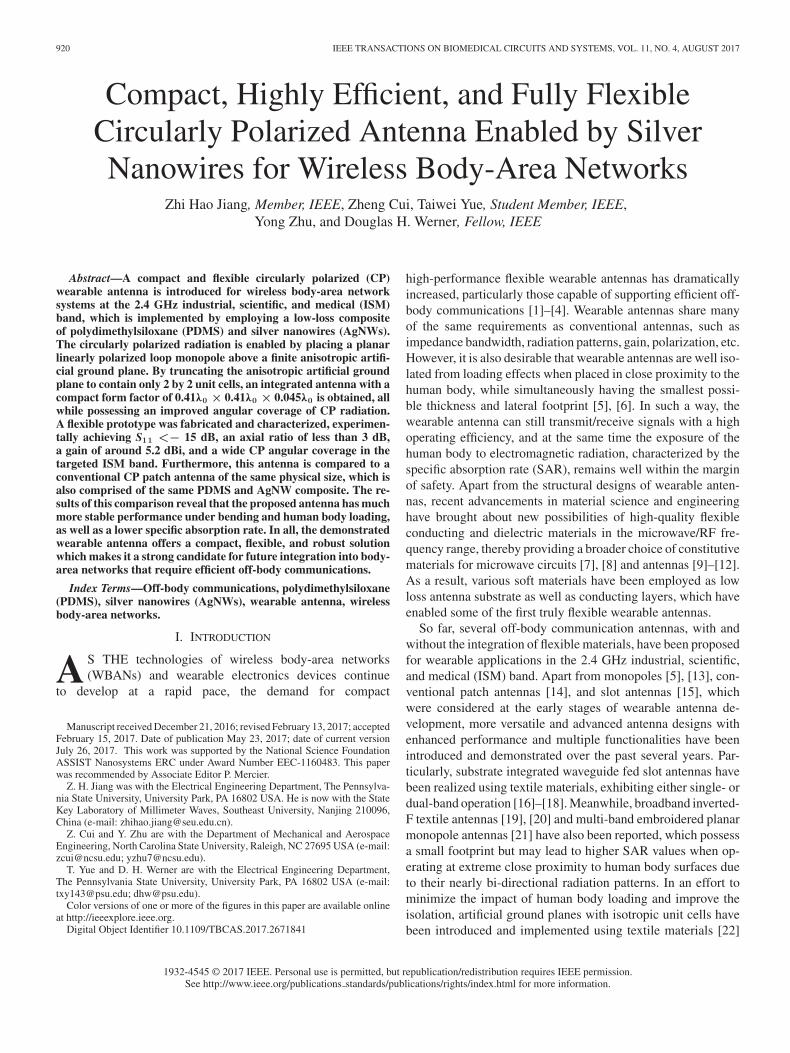
The layout of the compact and flexible CP wearable antennais illustrated in Fig. 1(a), where a fully planar configurationis adopted. The antenna consists of two components separatedby a thin foam spacer–a planar ring monopole oriented alongthe x-direction on the top and a custom designed AAG on thebottom. The side-fed scheme allows the antenna to be placed
922 IEEE TRANSACTIONS ON BIOMEDICAL CIRCUITS AND SYSTEMS, VOL. 11, NO. 4, AUGUST 2017
Fig. 1. (a) 3D view and (b) side view of the proposed CP antenna. Theoptimized dimensions are Ax = 50, Ay = 50, mx = 21, my = 21, wm = 4,g = 12, L = 8, ex = 15, ey = 15, cl = 11.6, wl = 5, da = 3.5, ds = 0.5,and dm = 1.5, all in millimeters. (c) Illustration of the field decomposition andcombination required for generating a RHCP radiated wave at broadside.
in very close proximity to the human body surface as com-pared to the bottom-fed topologies that have been consideredin previous CP wearable patch antennas [27], [31], [32]. Arti-ficial ground structures have been previously used in wearableantenna designs for both off-body [22]–[25] and on-body [45]communications, achieving a more compact antenna footprintand an improved degree of isolation. But these antennas werelimited to designs that radiate only linearly-polarized waves. Incontrast to a conventional ground plane, here the AAG containsa highly-truncated metasurface comprised of only a 2 by 2 arrayof modified loop resonators (MLRs) backed by a continuousconducting sheet. The MLR design was inspired by previousstudies on isotropic artificial ground unit cells, which revealedthat the loop resonator possesses a superior performance com-pared to cross-dipole or patch resonators [46]–[50]. In order tocreate the required anisotropic response, each MLR includes apair of diagonal chamfered corners along with a pair of slotscut out from its interior. As has been reported, when an x-polarized LP source is radiating above an artificial ground withan anisotropic reflection phase response, in general, the polar-ization of the resulting wave is elliptical (i.e., the wave directlyradiated from the source antenna combined with that reflectedfrom the AAG). To support right-handed (RH) CP radiation, asillustrated in Fig. 1(c), the reflection phases along the x + y andx – y directions must be around −90° and +90°, respectively,while at the same time the reflection magnitudes in the two
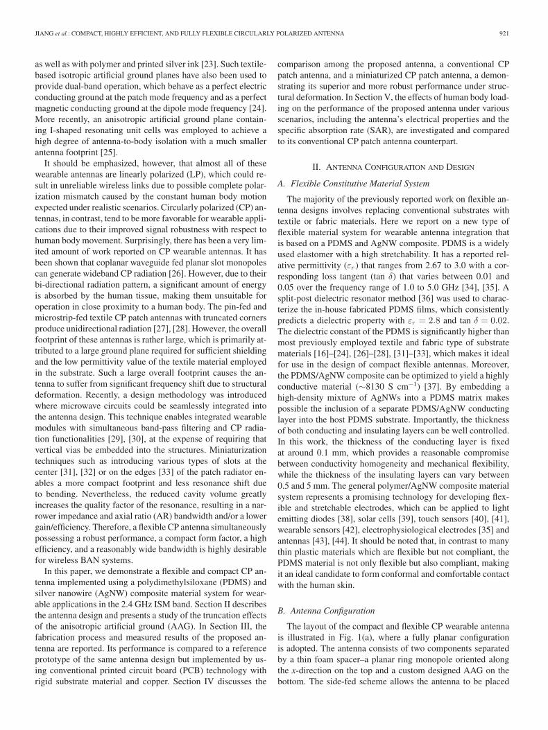
Fig. 2. (a) 3D view of the AAG unit cell. The illuminating TM polarizedplane wave is transformed into a TE polarized reflected wave. The dimensionsare w = 5, lx = 16.5, ly = 16.5, c = 10.2, ws = 2, ls = 1.5, and da = 3.5,all in millimeters. The inset defines the modes along the mirror symmetry linesof the MLR. (b) Reflection magnitudes and phases of a normally incident planewave for the two modes.
directions should be similar to each other. In this particularcase, the reflected wave of the x-polarized downward radiationfrom the source then becomes y-polarized with a 90° phase de-lay, thus enabling a RHCP radiated wave at broadside when it iscombined with the x-polarized upward radiation directly fromthe source [51], [52].
C. Unit Cell Design
The first step in the antenna design process is to consider theanisotropic reflection phase response of the AAG unit cell in aninfinite array environment with a periodic boundary conditionand Floquet port setup in the high frequency structure simulator(HFSS) [53]. As the inset of Fig. 2(a) shows, the MLR has itssymmetry lines along the x + y and x – y directions, therebytwo orthogonal resonating modes can be identified, denoted asMode 1 and Mode 2, respectively. For a normally incident planewave with its electric field polarized along these two directions,the reflection magnitudes and phases are different. Basically,the edge length, width, and slot size of the MLR as well asthe capacitive coupling between adjacent MLRs determine theresonant frequency of Mode 1. The degree to which the resonantfrequency of Mode 2 differs from Mode 1 is controlled by thechamfered corners. As shown in Fig. 2(b), the reflection phasefor Mode 1 is around −90° in the targeted band, while forMode 2 it is in the vicinity of +90°. In addition, the reflectionmagnitudes have similar values of about 0.9. It is important tonote that if the operational band is located in between the tworesonances, lower absorption loss can be achieved, thus ensuringa high efficiency for the flexible antenna.
JIANG et al.: COMPACT, HIGHLY EFFICIENT, AND FULLY FLEXIBLE CIRCULARLY POLARIZED ANTENNA 923
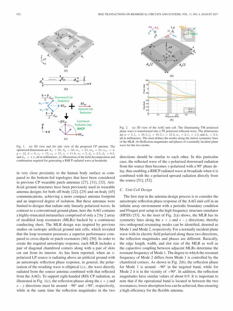
Fig. 3. Magnitude and phase for a TE polarized reflected wave with a TMpolarized incident wave at different angles of incidence.
The majority of the downward radiated waves emanating fromthe planar monopole will impinge on the AAG at angles close tonormal incidence. However, since the distance between the twocomponents is on a deep subwavelength scale, there also existswaves with a non-zero transverse wavenumber, i.e. waves thatobliquely illuminate the AAG. Thus, the angular response ofthe AAG needs to be taken into account. For oblique incidenceangles, the requirement of the AAG is to transform a transversemagnetic (TM) polarized incident wave into a transverse electric(TE) polarized wave with its electric field polarized along the y-direction with a 90° phase delay. It can be observed from Fig. 3that, in the targeted band, the magnitude and phase of the TEpolarized reflected wave is larger than 0.84 and around −90°,respectively. The ratio between the power of the reflected TEand TM polarized wave is more than 13 dB, indicating that theTM polarized incident wave is almost entirely transformed into aTE polarized reflected wave within a certain field-of-view. Thismakes possible a wide axial ratio <3 dB beamwidth (ARBW),as will be shown in the following sections.
D. Integrated Antenna Design and Performance
Once the AAG unit cell has been designed, a planar monopoleis added above the AAG structure with a separation distance ofds . Since a strongly truncated AAG with only 2 by 2 unit cellsis chosen in order to obtain a compact footprint, the radiatingelement of the monopole is located above the area in the mid-dle of the four MLRs. In order to excite the four MLRs moreefficiently, a rectangular loop monopole was employed whichforces the currents to flow at locations near the corners of allfour MLRs. Due to the truncation of the AAG, the dimensionsof the MLRs need to be slightly tuned together with the planarloop monopole for the best performance metric in the targetedband, including the input impedance, gain, front-to-back totalradiation (FBTR) ratio, AR bandwidth and beamwidth. Here,the FBTR ratio is defined as the ratio between the total radiatedpower in the half-space above the antenna and that in the half-space beneath the antenna. This represents a more meaningfulcharacterization of the back radiation of an antenna towardsthe human body in wearable scenarios than the conventionalfront-to-back (FB) ratio.
The final tuned version of the integrated antenna has a formfactor of 0.41 λ0 × 0.41 λ0 × 0.045 λ0 , where λ0 is the wave-length at the center frequency of 2.44 GHz. The simulated S11 ,shown in Fig. 4(a), has a −10 dB bandwidth that ranges from
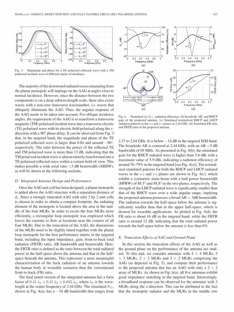
Fig. 4. Simulated (a) S11 , radiation efficiency, (b) broadside AR, and RHCPgain of the proposed antenna. (c) Simulated normalized RHCP and LHCPradiation patterns in the x-z and y-z planes at 2.44 GHz. (d) Simulated FB ratioand FBTR ratio of the proposed antenna.
2.37 to 2.64 GHz. It is below −14 dB in the targeted ISM band.The broadside AR is centered at 2.44 GHz, with an AR <3 dBbandwidth of 69 MHz. As presented in Fig. 4(b), the simulatedgain for the RHCP radiated wave is higher than 5.6 dBi with amaximum value of 5.9 dBi, indicating a radiation efficiency ofaround 76–79% in the targeted band [see Fig. 4(a)]. The normal-ized simulated patterns for both the RHCP and LHCP radiatedwaves in the x-z and y-z planes are shown in Fig. 4(c), whichexhibit a symmetric main beam with a half power beamwidth(HPBW) of 88.5° and 88.8° in the two planes, respectively. Thestrength of the LHCP radiated wave is significantly smaller thanthat of the RHCP wave over a wide angular range, implyingthe proposed antenna possesses a broad AR < 3dB beamwidth.The radiation towards the half-space below the antenna is sig-nificantly smaller than that in the upper half-space, which isdesired for wearable applications. As plotted in Fig. 4(d), theFB ratio is about 16 dB in the targeted band, while the FBTRratio is around 12 dB, indicating that the total radiated powertowards the half-space below the antenna is less than 6%.
E. Truncation Effects of AAG and Ground Plane
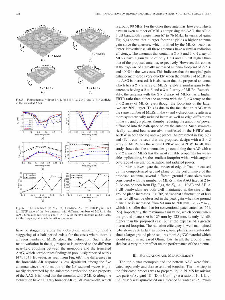
In this section the truncation effects of the AAG as well asthe ground plane on the performance of the antenna are stud-ied. To this end, we consider antennas with 4 × 4 MLRs, 3× 3 MLRs, 2 × 3 MLRs and 3 × 2 MLRs comprising theAAG (as depicted in Fig. 5), and compare their performanceto the proposed antenna that has an AAG with only a 2 × 2array of MLRs. As shown in Fig. 6(a), all five antennas exhibitgood impedance matching in the targeted band. Interestingly,a broadband response can be observed for the antennas with 3MLRs along the x-direction. This can be attributed to the factthat the monopole radiator and the MLRs in the middle row
924 IEEE TRANSACTIONS ON BIOMEDICAL CIRCUITS AND SYSTEMS, VOL. 11, NO. 4, AUGUST 2017
Fig. 5. Four antennas with (a) 4 × 4, (b) 3 × 3, (c) 2 × 3, and (d) 3 × 2 MLRsin the truncated AAG.
Fig. 6. The simulated (a) S11 , (b) broadside AR, (c) RHCP gain, and(d) FBTR ratio of the five antennas with different numbers of MLRs in theAAG. Simulated (e) HPBW and (f) ARBW of the five antennas at 2.44 GHz,i.e. the frequency at which the AR is minimum.
have no staggering along the x-direction, while in contrast astaggering of a half period exists for the cases where there isan even number of MLRs along the x-direction. Such a dra-matic variation in the S11 response is ascribed to the differentnear-field coupling between the monopole and the truncatedAAG, which corroborates findings in previously reported works[47], [54]. However, as seen from Fig. 6(b), the differences inthe broadside AR response is less significant among the fiveantennas since the formation of the CP radiated waves is pri-marily determined by the anisotropic reflection phase propertyof the AAG. It is noted that the antennas with 3 MLRs along thex-direction have a slightly broader AR < 3 dB bandwidth, which
is around 90 MHz. For the other three antennas, however, whichhave an even number of MRLs comprising the AAG, the AR <3 dB bandwidth ranges from 67 to 76 MHz. In terms of gain,Fig. 6(c) shows that a larger footprint yields a higher antennagain since the aperture, which is filled by the MLRs, becomeslarger. Nevertheless, all these antennas have a similar radiationefficiency. The antennas that contain a 3 × 3 and 4 × 4 array ofMLRs have a gain value of only 1 dB and 1.3 dB higher thanthat of the proposed antenna, respectively. However, this comesat the expense of a greatly increased antenna footprint of 225%and 400% in the two cases. This indicates that the marginal gainenhancement drops very quickly when the number of MLRs inthe AAG is increased. It is also seen that the proposed antenna,which has a 2 × 2 array of MLRs, yields a similar gain to theantennas having a 2 × 3 and a 3 × 2 array of MLRs. Remark-ably, the antenna with the 2 × 2 array of MLRs has a higherFBTR ratio than either the antenna with the 2 × 3 array or the3 × 2 array of MLRs, even though the footprints of the lattertwo are 50% larger. This is due to the fact that an AAG withthe same number of MLRs in the x- and y-directions results in amore symmetrically radiated beam as well as edge diffractionsin the x-z and y-z planes, thereby reducing the amount of powerdiffracted into the half-space below the antenna. Such symmet-rically radiated beams are also manifested in the HPBW andARBW in both the x-z and y-z planes. As presented in Fig. 6(e)and (f), it can be seen that the proposed design with a 2 × 2array of MLRs has the widest HPBW and ARBW. In all, thisstudy shows that the antenna design containing the AAG with a2 × 2 array of MLRs has the most suitable properties for wear-able applications, i.e. the smallest footprint with a wide angularcoverage of circular polarization and radiated power.
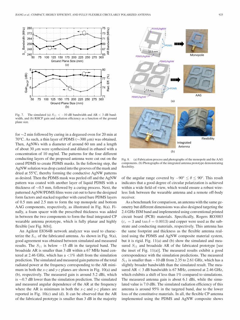
In order to investigate the impact of edge diffraction causedby the compact-sized ground plane on the performance of theproposed antenna, several different ground plane sizes wereconsidered with the number of MLRs in the AAG fixed at 2 by2. As can be seen from Fig. 7(a), the S11 < −10 dB and AR <3 dB bandwidths are both well maintained as the size of theground plane increases. Fig. 7(b) shows that a fluctuation of lessthan 1.4 dB can be observed in the peak gain when the groundplane size is increased from 50 mm to 300 mm, i.e. ∼ 2.5λ0 ,which is smaller than that for conventional patch antennas [55],[56]. Importantly, the maximum gain value, which occurs whenthe ground plane size is 125 mm by 125 mm, is only 1.1 dBhigher than the proposed case, but at the expense of a greatlyincreased footprint. The radiation efficiency is well-maintainedto be above 77%. In fact, a smaller ground plane size is preferablesince a larger ground plane requires more AgNW material whichwould result in increased Ohmic loss. In all, the ground planesize has a very minor effect on the performance of the antenna.
III. FABRICATION AND MEASUREMENTS
The top planar monopole and the bottom AAG were fabri-cated separately and then assembled together. The first step inthe fabricated process was to prepare liquid PDMS by mixingtwo parts of Sylgard 184 (Dow Corning) at a ratio of 10:1. Liq-uid PDMS was spin-coated on a cleaned Si wafer at 250 r/min
JIANG et al.: COMPACT, HIGHLY EFFICIENT, AND FULLY FLEXIBLE CIRCULARLY POLARIZED ANTENNA 925
Fig. 7. The simulated (a) S11 < −10 dB bandwidth and AR < 3 dB band-width, and (b) RHCP gain and radiation efficiency as a function of the groundplane size.
for ∼2 min followed by curing in a degassed oven for 20 min at70°C. As such, a thin layer of PDMS (∼300 μm) was obtained.Then, AgNWs with a diameter of around 60 nm and a lengthof about 30 μm were synthesized and diluted in ethanol with aconcentration of 10 mg/ml. The patterns for the four differentconducting layers of the proposed antenna were cut out on thecured PDMS to create PDMS masks. In the following step, theAgNW solution was drop casted into the grooves of the mask anddried at 55°C, thereby forming the conductive AgNW patternsas desired. Then the PDMS mask was peeled off and the AgNWpattern was coated with another layer of liquid PDMS with athickness of ∼0.5 mm, followed by a curing process. Next, thepatterned AgNW/PDMS films were cut out to have the designedform factors and stacked together with cured bare PDMS layersof 0.5 mm and 2.5 mm to form the top monopole and bottomAAG components, respectively, as illustrated in Fig. 8(a). Fi-nally, a foam spacer with the prescribed thickness was addedin between the two components to form the final integrated CPwearable antenna prototype, which is fully planar and highlyflexible [see Fig. 8(b)].
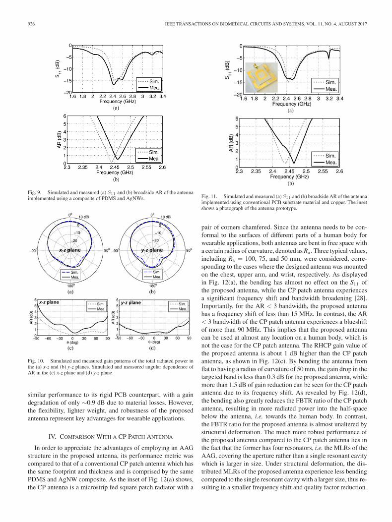
An Agilent E8364B network analyzer was used to charac-terize the S11 of the fabricated antenna. As shown in Fig. 9(a),good agreement was obtained between simulated and measuredresults. The S11 is below −15 dB in the targeted band. Thebroadside AR is smaller than 3 dB within a 67 MHz band cen-tered at 2.46 GHz, which has a <1% shift from the simulationprediction. The simulated and measured gain patterns of the totalradiated power at the frequency corresponding to the AR mini-mum in both the x-z and y-z planes are shown in Fig. 10(a) and(b), respectively. The measured gain is around 5.2 dBi, whichis ∼0.7 dB lower than the simulation prediction. The simulatedand measured angular dependence of the AR at the frequencywhere the AR is minimum in both the x-z and y-z planes arereported in Fig. 10(c) and (d). It can be observed that the ARof the fabricated prototype is smaller than 3 dB in the majority
Fig. 8. (a) Fabrication process and photographs of the monopole and the AAGcomponents. (b) Photographs of the integrated antenna prototype demonstratingflexibility.
of the angular range covered by −90° ≤ θ ≤ 90°. This resultindicates that a good degree of circular polarization is achievedwithin a wide field-of-view, which would ensure a robust wire-less link between the wearable antenna and a remote off-bodyreceiver.
As a benchmark for comparison, an antenna with the same ge-ometry but different dimensions was also designed targeting the2.4 GHz ISM band and implemented using conventional printedcircuit board (PCB) materials. Specifically, Rogers RO3003(εr = 3 and tan δ = 0.0013) and copper were used as the sub-strate and conducting materials, respectively. This antenna hasthe same footprint and thickness as the flexible antenna real-ized using the PDMS and AgNW composite material system,but it is rigid. Fig. 11(a) and (b) show the simulated and mea-sured S11 and broadside AR of the fabricated prototype [seethe inset of Fig. 11(a)]. The measured results exhibit a goodcorrespondence with the simulation predictions. The measuredS11 is smaller than −10 dB from 2.35 to 2.61 GHz, which has aslightly broader bandwidth than the simulated result. The mea-sured AR < 3 dB bandwidth is 67 MHz, centered at 2.46 GHz,which exhibits a shift of less than 1% compared to simulations.The measured antenna gain is about 6.1 dBi, while the simu-lated value is 7.0 dBi. The simulated radiation efficiency of thisantenna is around 95% in the targeted band, due to the lowerloss of the constitutive materials. In all, the flexible CP antennaimplemented using the PDMS and AgNW composite shows
926 IEEE TRANSACTIONS ON BIOMEDICAL CIRCUITS AND SYSTEMS, VOL. 11, NO. 4, AUGUST 2017
Fig. 9. Simulated and measured (a) S11 and (b) broadside AR of the antennaimplemented using a composite of PDMS and AgNWs.
Fig. 10. Simulated and measured gain patterns of the total radiated power inthe (a) x-z and (b) y-z planes. Simulated and measured angular dependence ofAR in the (c) x-z plane and (d) y-z plane.
similar performance to its rigid PCB counterpart, with a gaindegradation of only ∼0.9 dB due to material losses. However,the flexibility, lighter weight, and robustness of the proposedantenna represent key advantages for wearable applications.
IV. COMPARISON WITH A CP PATCH ANTENNA
In order to appreciate the advantages of employing an AAGstructure in the proposed antenna, its performance metric wascompared to that of a conventional CP patch antenna which hasthe same footprint and thickness and is comprised by the samePDMS and AgNW composite. As the inset of Fig. 12(a) shows,the CP antenna is a microstrip fed square patch radiator with a
Fig. 11. Simulated and measured (a) S11 and (b) broadside AR of the antennaimplemented using conventional PCB substrate material and copper. The insetshows a photograph of the antenna prototype.
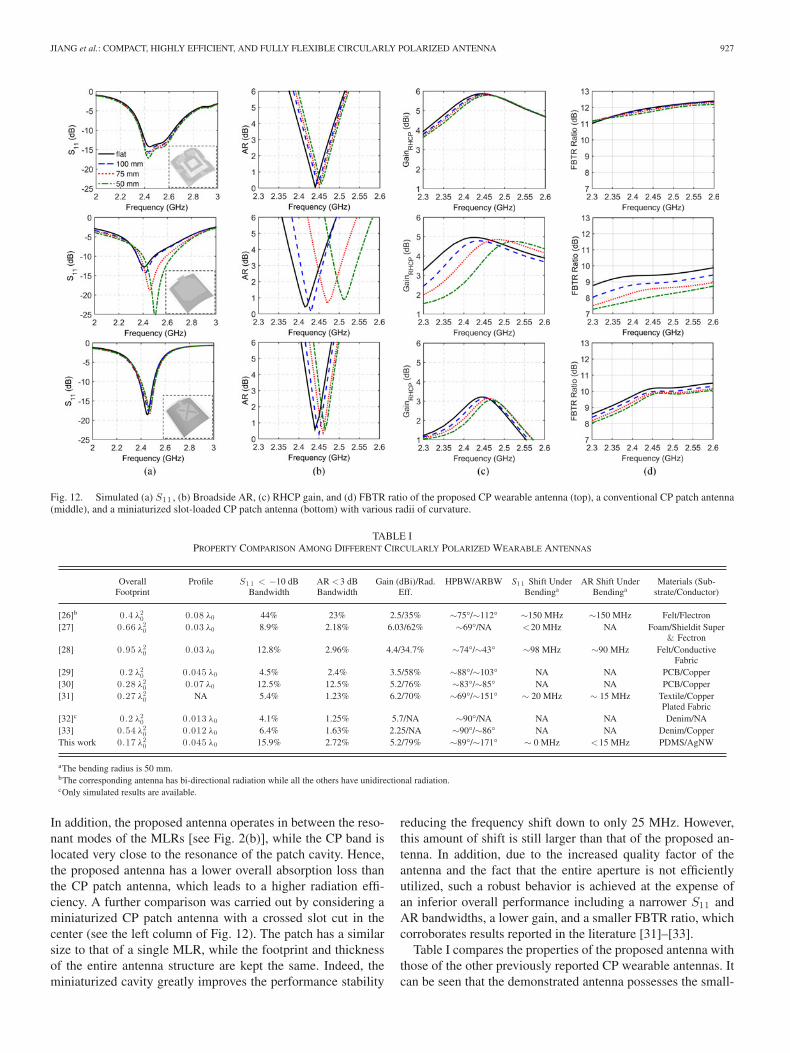
pair of corners chamfered. Since the antenna needs to be con-formal to the surfaces of different parts of a human body forwearable applications, both antennas are bent in free space witha certain radius of curvature, denoted as Ra . Three typical values,including Ra = 100, 75, and 50 mm, were considered, corre-sponding to the cases where the designed antenna was mountedon the chest, upper arm, and wrist, respectively. As displayedin Fig. 12(a), the bending has almost no effect on the S11 ofthe proposed antenna, while the CP patch antenna experiencesa significant frequency shift and bandwidth broadening [28].Importantly, for the AR < 3 bandwidth, the proposed antennahas a frequency shift of less than 15 MHz. In contrast, the AR< 3 bandwidth of the CP patch antenna experiences a blueshiftof more than 90 MHz. This implies that the proposed antennacan be used at almost any location on a human body, which isnot the case for the CP patch antenna. The RHCP gain value ofthe proposed antenna is about 1 dB higher than the CP patchantenna, as shown in Fig. 12(c). By bending the antenna fromflat to having a radius of curvature of 50 mm, the gain drop in thetargeted band is less than 0.3 dB for the proposed antenna, whilemore than 1.5 dB of gain reduction can be seen for the CP patchantenna due to its frequency shift. As revealed by Fig. 12(d),the bending also greatly reduces the FBTR ratio of the CP patchantenna, resulting in more radiated power into the half-spacebelow the antenna, i.e. towards the human body. In contrast,the FBTR ratio for the proposed antenna is almost unaltered bystructural deformation. The much more robust performance ofthe proposed antenna compared to the CP patch antenna lies inthe fact that the former has four resonators, i.e. the MLRs of theAAG, covering the aperture rather than a single resonant cavitywhich is larger in size. Under structural deformation, the dis-tributed MLRs of the proposed antenna experience less bendingcompared to the single resonant cavity with a larger size, thus re-sulting in a smaller frequency shift and quality factor reduction.
JIANG et al.: COMPACT, HIGHLY EFFICIENT, AND FULLY FLEXIBLE CIRCULARLY POLARIZED ANTENNA 927
Fig. 12. Simulated (a) S11 , (b) Broadside AR, (c) RHCP gain, and (d) FBTR ratio of the proposed CP wearable antenna (top), a conventional CP patch antenna(middle), and a miniaturized slot-loaded CP patch antenna (bottom) with various radii of curvature.
TABLE IPROPERTY COMPARISON AMONG DIFFERENT CIRCULARLY POLARIZED WEARABLE ANTENNAS
OverallFootprint
Profile S1 1 < −10 dBBandwidth
AR <3 dBBandwidth
Gain (dBi)/Rad.Eff.
HPBW/ARBW S1 1 Shift UnderBendinga
AR Shift UnderBendinga
Materials (Sub-strate/Conductor)
[26]b 0.4 λ20 0.08 λ0 44% 23% 2.5/35% ∼75°/∼112° ∼150 MHz ∼150 MHz Felt/Flectron
[27] 0.66 λ20 0.03 λ0 8.9% 2.18% 6.03/62% ∼69°/NA <20 MHz NA Foam/Shieldit Super
& Fectron[28] 0.95 λ2
0 0.03 λ0 12.8% 2.96% 4.4/34.7% ∼74°/∼43° ∼98 MHz ∼90 MHz Felt/ConductiveFabric
[29] 0.2 λ20 0.045 λ0 4.5% 2.4% 3.5/58% ∼88°/∼103° NA NA PCB/Copper
[30] 0.28 λ20 0.07 λ0 12.5% 12.5% 5.2/76% ∼83°/∼85° NA NA PCB/Copper
[31] 0.27 λ20 NA 5.4% 1.23% 6.2/70% ∼69°/∼151° ∼ 20 MHz ∼ 15 MHz Textile/Copper
Plated Fabric[32]c 0.2 λ2
0 0.013 λ0 4.1% 1.25% 5.7/NA ∼90°/NA NA NA Denim/NA[33] 0.54 λ2
0 0.012 λ0 6.4% 1.63% 2.25/NA ∼90°/∼86° NA NA Denim/CopperThis work 0.17 λ2
0 0.045 λ0 15.9% 2.72% 5.2/79% ∼89°/∼171° ∼ 0 MHz <15 MHz PDMS/AgNW
aThe bending radius is 50 mm.bThe corresponding antenna has bi-directional radiation while all the others have unidirectional radiation.cOnly simulated results are available.
In addition, the proposed antenna operates in between the reso-nant modes of the MLRs [see Fig. 2(b)], while the CP band islocated very close to the resonance of the patch cavity. Hence,the proposed antenna has a lower overall absorption loss thanthe CP patch antenna, which leads to a higher radiation effi-ciency. A further comparison was carried out by considering aminiaturized CP patch antenna with a crossed slot cut in thecenter (see the left column of Fig. 12). The patch has a similarsize to that of a single MLR, while the footprint and thicknessof the entire antenna structure are kept the same. Indeed, theminiaturized cavity greatly improves the performance stability
reducing the frequency shift down to only 25 MHz. However,this amount of shift is still larger than that of the proposed an-tenna. In addition, due to the increased quality factor of theantenna and the fact that the entire aperture is not efficientlyutilized, such a robust behavior is achieved at the expense ofan inferior overall performance including a narrower S11 andAR bandwidths, a lower gain, and a smaller FBTR ratio, whichcorroborates results reported in the literature [31]–[33].
Table I compares the properties of the proposed antenna withthose of the other previously reported CP wearable antennas. Itcan be seen that the demonstrated antenna possesses the small-
928 IEEE TRANSACTIONS ON BIOMEDICAL CIRCUITS AND SYSTEMS, VOL. 11, NO. 4, AUGUST 2017
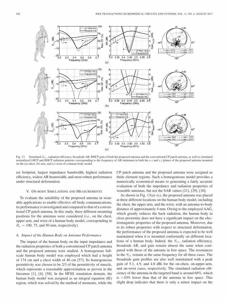
Fig. 13. Simulated S11 , radiation efficiency, broadside AR, RHCP gain of both the proposed antenna and the conventional CP patch antenna, as well as simulatednormalized LHCP and RHCP radiation patterns corresponding to the frequency of AR minimum in both the x-z and y-z planes of the proposed antenna mountedon the (a) chest, (b) arm, and (c) wrist of a human body model.
est footprint, largest impedance bandwidth, highest radiationefficiency, widest AR beamwidth, and most robust performanceunder structural deformation.
V. ON-BODY SIMULATIONS AND MEASUREMENTS
To evaluate the suitability of the proposed antenna in wear-able applications to enable effective off-body communications,its performance is investigated and compared to that of a conven-tional CP patch antenna. In this study, three different mountingpositions for the antennas were considered (i.e., on the chest,upper arm, and wrist of a human body model, corresponding toRa = 100, 75, and 50 mm, respectively).
A. Impact of the Human Body on Antenna Performance
The impact of the human body on the input impedance andthe radiation properties of both a conventional CP patch antennaand the proposed antenna were studied. A homogenous full-scale human body model was employed which had a heightof 174 cm and a chest width of 46 cm [57]. Its homogeneouspermittivity was chosen to be 2/3 of the permittivity of muscle,which represents a reasonable approximation as proven in theliterature [1], [4], [58]. In the HFSS simulation domain, thehuman body model was assigned as an integral equation (IE)region, which was solved by the method of moments, while the
CP patch antenna and the proposed antenna were assigned asfinite element regions. Such a homogeneous model provides anumerically economical means to generating a fairly accurateevaluation of both the impedance and radiation properties ofwearable antennas, but not the SAR values [21], [29], [30].
As shown in Fig. 13(a)–(c), the proposed antenna was placedat three different locations on the human body model, includingthe chest, the upper arm, and the wrist, with an antenna-to-bodydistance of approximately 4 mm. Owing to the employed AAG,which greatly reduces the back radiation, the human body inclose proximity does not have a significant impact on the elec-tromagnetic properties of the proposed antenna. Moreover, dueto its robust properties with respect to structural deformation,the performance of the proposed antenna is expected to be wellmaintained when it is mounted conformally on different loca-tions of a human body. Indeed, the S11 , radiation efficiency,broadside AR, and gain remain almost the same when com-pared with those of the antenna in free space. The resonancesin the S11 remain at the same frequency for all three cases. Thebroadside gain profiles are also well maintained with a peakgain of 5.1, 4.9, and 4.8 dBi for the on-chest, on-upper-arm,and on-wrist cases, respectively. The simulated radiation effi-ciency of the antenna in the targeted band is around 68%, whichis ∼10% lower than that of the antenna in free space. Thisslight drop indicates that there is only a minor impact on the
JIANG et al.: COMPACT, HIGHLY EFFICIENT, AND FULLY FLEXIBLE CIRCULARLY POLARIZED ANTENNA 929
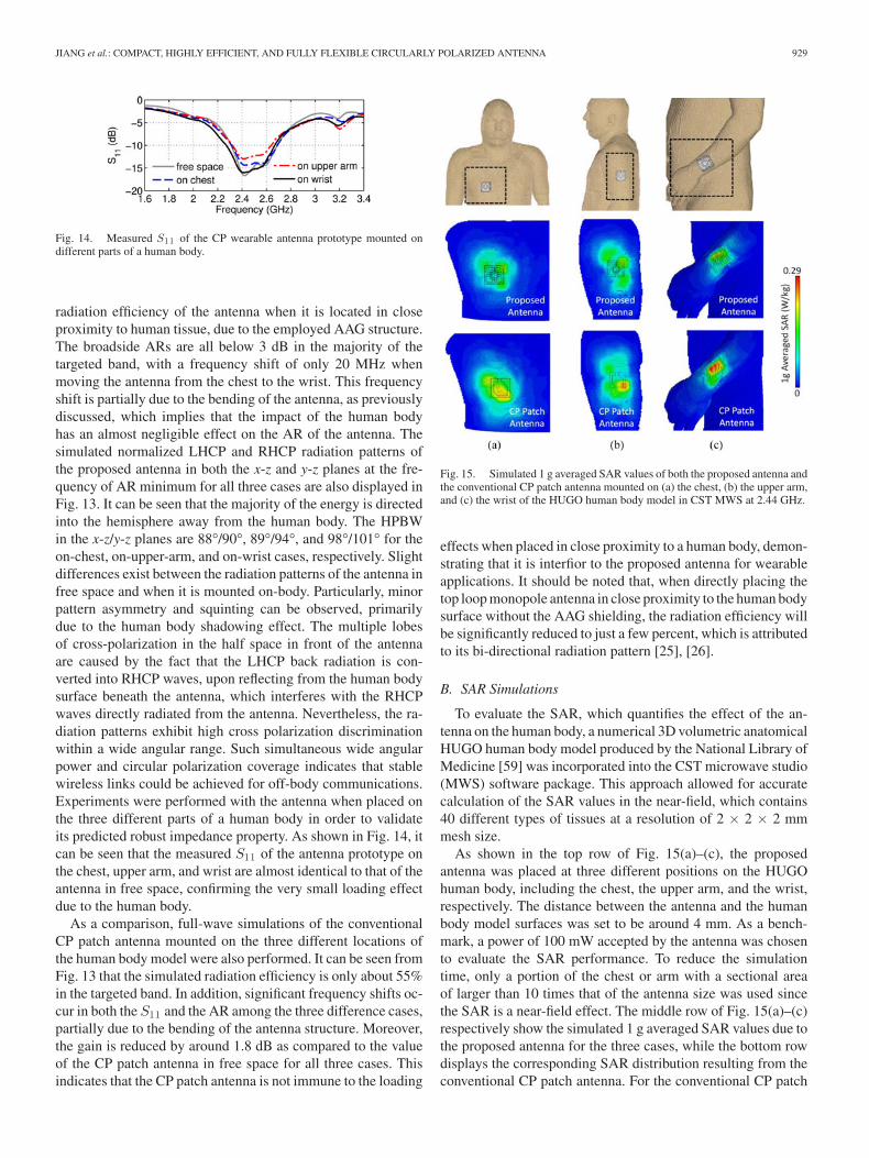
Fig. 14. Measured S11 of the CP wearable antenna prototype mounted ondifferent parts of a human body.
radiation efficiency of the antenna when it is located in closeproximity to human tissue, due to the employed AAG structure.The broadside ARs are all below 3 dB in the majority of thetargeted band, with a frequency shift of only 20 MHz whenmoving the antenna from the chest to the wrist. This frequencyshift is partially due to the bending of the antenna, as previouslydiscussed, which implies that the impact of the human bodyhas an almost negligible effect on the AR of the antenna. Thesimulated normalized LHCP and RHCP radiation patterns ofthe proposed antenna in both the x-z and y-z planes at the fre-quency of AR minimum for all three cases are also displayed inFig. 13. It can be seen that the majority of the energy is directedinto the hemisphere away from the human body. The HPBWin the x-z/y-z planes are 88°/90°, 89°/94°, and 98°/101° for theon-chest, on-upper-arm, and on-wrist cases, respectively. Slightdifferences exist between the radiation patterns of the antenna infree space and when it is mounted on-body. Particularly, minorpattern asymmetry and squinting can be observed, primarilydue to the human body shadowing effect. The multiple lobesof cross-polarization in the half space in front of the antennaare caused by the fact that the LHCP back radiation is con-verted into RHCP waves, upon reflecting from the human bodysurface beneath the antenna, which interferes with the RHCPwaves directly radiated from the antenna. Nevertheless, the ra-diation patterns exhibit high cross polarization discriminationwithin a wide angular range. Such simultaneous wide angularpower and circular polarization coverage indicates that stablewireless links could be achieved for off-body communications.Experiments were performed with the antenna when placed onthe three different parts of a human body in order to validateits predicted robust impedance property. As shown in Fig. 14, itcan be seen that the measured S11 of the antenna prototype onthe chest, upper arm, and wrist are almost identical to that of theantenna in free space, confirming the very small loading effectdue to the human body.
As a comparison, full-wave simulations of the conventionalCP patch antenna mounted on the three different locations ofthe human body model were also performed. It can be seen fromFig. 13 that the simulated radiation efficiency is only about 55%in the targeted band. In addition, significant frequency shifts oc-cur in both the S11 and the AR among the three difference cases,partially due to the bending of the antenna structure. Moreover,the gain is reduced by around 1.8 dB as compared to the valueof the CP patch antenna in free space for all three cases. Thisindicates that the CP patch antenna is not immune to the loading
Fig. 15. Simulated 1 g averaged SAR values of both the proposed antenna andthe conventional CP patch antenna mounted on (a) the chest, (b) the upper arm,and (c) the wrist of the HUGO human body model in CST MWS at 2.44 GHz.
effects when placed in close proximity to a human body, demon-strating that it is interfior to the proposed antenna for wearableapplications. It should be noted that, when directly placing thetop loop monopole antenna in close proximity to the human bodysurface without the AAG shielding, the radiation efficiency willbe significantly reduced to just a few percent, which is attributedto its bi-directional radiation pattern [25], [26].
B. SAR Simulations
To evaluate the SAR, which quantifies the effect of the an-tenna on the human body, a numerical 3D volumetric anatomicalHUGO human body model produced by the National Library ofMedicine [59] was incorporated into the CST microwave studio(MWS) software package. This approach allowed for accuratecalculation of the SAR values in the near-field, which contains40 different types of tissues at a resolution of 2 × 2 × 2 mmmesh size.
As shown in the top row of Fig. 15(a)–(c), the proposedantenna was placed at three different positions on the HUGOhuman body, including the chest, the upper arm, and the wrist,respectively. The distance between the antenna and the humanbody model surfaces was set to be around 4 mm. As a bench-mark, a power of 100 mW accepted by the antenna was chosento evaluate the SAR performance. To reduce the simulationtime, only a portion of the chest or arm with a sectional areaof larger than 10 times that of the antenna size was used sincethe SAR is a near-field effect. The middle row of Fig. 15(a)–(c)respectively show the simulated 1 g averaged SAR values due tothe proposed antenna for the three cases, while the bottom rowdisplays the corresponding SAR distribution resulting from theconventional CP patch antenna. For the conventional CP patch

930 IEEE TRANSACTIONS ON BIOMEDICAL CIRCUITS AND SYSTEMS, VOL. 11, NO. 4, AUGUST 2017
antenna, the peak 1 g averaged SAR varies from 0.22 to 0.29W/kg. For the proposed antenna, however, it can be observedthat, for all three cases, the peak 1 g averaged SAR value rangesfrom 0.13 to 0.18 W/kg. This indicates that the maximum al-lowed accepted power for the proposed antenna is about 65%higher than that for the CP patch antenna, thereby leading to alarger maximum communication distance of about 30%. Thesevalues are not only well below the 1.6 W/kg specification pro-vided by the Federal Communication Commission (FCC) [60],but also much smaller than those of the conventional CP patchantenna.
VI. CONCLUSIONS
In summary, we have reported a methodology to design com-pact and robust CP wearable antennas using an AAG with only2 by 2 unit cells. A composite of PDMS and AgNWs was em-ployed to implement the antenna prototype, thereby achievinga fully planar and highly flexible module. Experimental resultswere found to be in strong agreement with the simulation pre-dictions, thus confirming the proposed design. The reported an-tenna was shown to have a robust performance against structuraldeformation and human body loading, which is far superior to aconventional CP patch antenna. Moreover, the proposed antennaexhibits small SAR values in several examined wearable sce-narios. The demonstrated compact, flexible, and highly efficientCP antenna is expected to find potential applications in variousadvanced wearable devices for off-body communications.
REFERENCES
[1] P. S. Hall and Y. Hao, Antennas and Propagation for Body-Centric WirelessCommunications. Norwood, MA, USA: Artech House, 2012.
[2] G. Z. Yang, Body Sensor Networks. Berlin, Germany: Springer, 2006.[3] C. S. Nikita, Handbook of Biomedical Telemetry. Hoboken, NJ, USA:
Wiley-IEEE Press, 2014.[4] D. H. Werner and Z. H. Jiang, Electromagnetics of Body Area Networks:
Antennas, Propagation, and RF Systems. Hoboken, NJ, USA: Wiley/IEEEPress, 2016.
[5] P. S. Hall et al., “Antennas and propagation for on-body communicationsystems,” IEEE Antennas Propag. Mag., vol. 49, no. 3, pp. 41–58, Jun.2007.
[6] N. H. M. Rais, P. J. Soh, F. Malek, S. Ahmad, N. Hashim, and P. S. Hall, “Areview of wearable antenna,” in Proc. Loughborough Antennas Propag.Conf., 2009, pp. 225–228.
[7] R. Moro, S. Agneessens, H. Rogier, A. Dierck, and M. Bozzi, “Textilemicrowave components in substrate integrated waveguide technology,”IEEE Trans. Microw. Theory Tech., vol. 63, no. 2, pp. 422–432, Feb. 2015.
[8] S. Yao and Y. Zhu, “Nanomaterial-enabled stretchable conductors: strate-gies, materials and devices,” Adv. Mater., vol. 27, no. 9, pp. 1480–1511,Jan. 2015.
[9] C. A. Winterhalter et al., “Development of electronic textiles to sup-port networks, communications, and medical applications in future U.S.Military protective clothing systems,” IEEE Trans. Inf. Technol. Biomed.,vol. 9, no. 3, pp. 402–406, Sep. 2005.
[10] M. Klemm and G. Troester, “Textile UWB antennas for wireless body areanetworks,” IEEE Trans. Antennas Propag., vol. 54, no. 11, pp. 3192–3197,Nov. 2006.
[11] S. Sankaralingam and B. Gupta, “Determination of dielectric constant offabric materials and their use as substrates for design and development ofantennas for wearable applications,” IEEE Trans. Instrum. Meas., vol. 59,no. 12, pp. 3122–3130, Dec. 2010.
[12] P. J. Soh, G. A. E. Vandenbosch, S. L. Ooi, and M. R. N. Husna, “Wearabledual-band Sierpinski fractal PIFA using conductive fabric,” Electron. Lett.,vol. 47, no. 6, pp. 365–367, Mar. 2011.
[13] M. N. Suma, P. C. Bybi, and P. Mohanan, “A wideband printed monopoleantenna for 2.45 GHz WLAN applications,” Microw. Opt. Technol. Lett.,vol. 48, no. 5, pp. 871–873, May 2006.
[14] A. Alomainy et al., “Statistical analysis and performance evaluation foron-body radio propagation with microstrip patch antennas,” IEEE Trans.Antennas Propag., vol. 55, no. 1, pp. 245–248, Jan. 2007.
[15] N. Haga, K. Saito, M. Takahashi, and K. Ito, “Characteristics of cavity slotantenna for body-area networks,” IEEE Trans. Antennas Propag., vol. 57,no. 4, pp. 837–843, Apr. 2009.
[16] S. Agneessens and H. Rogier, “Compact half diamond dual-band textileHMSIW on-body antenna,” IEEE Trans. Antennas Propag., vol. 62, no. 5,pp. 2374–2381, May 2014.
[17] S. Agneessens, S. Lemey, T. Vervust, and H. Rogier, “Wearable, small,and robust: the circular quarter-mode textile antenna,” IEEE AntennasWireless Propag. Lett., vol. 14, pp. 1482–1485, Jan. 2015.
[18] S. Yan, P. J. Soh, and G. A. E. Vandenbosch, “Dual-band textile MIMO an-tenna based on substrate-integrated waveguide (SIW) technology,” IEEETrans. Antennas Propag., vol. 63, no. 11, pp. 4640–4647, Nov. 2015.
[19] P. J. Soh, G. A. E. Vandenbosch, S. L. Ooi, and N. H. M. Rais, “Designof a broadband all-textile slotted PIFA,” IEEE Trans. Antennas Propag.,vol. 60, no. 1, pp. 379–384, Jan. 2012.
[20] W. El Hajj, C. Person, and J. Wiart, “A novel investigation of a broadbandintegrated inverted-F antenna design; application for wearable antenna,”IEEE Trans. Antennas Propag., vol. 62, no. 7, pp. 3843–3846, Jul. 2014.
[21] Z. Wang, L. Z. Lee, D. Psychoudakis, and J. L. Volakis, “Embroideredmultiband body-worn antenna for GSM/PCS/WLAN communications,”IEEE Trans. Antennas Propag., vol. 62, no. 6, pp. 3321–3329, Jun. 2014.
[22] S. Zhu and R. Langley, “Dual-band wearable textile antenna on an EBGsubstrate,” IEEE Trans. Antennas Propag., vol. 57, no. 4, pp. 926–935,Apr. 2009.
[23] H. R. Raad, A. I. Abbosh, H. M. Al-Rizzo, and D. G. Rucker, “Flexibleand compact AMC based antenna for telemedicine applications,” IEEETrans. Antennas Propag., vol. 61, no. 2, pp. 524–531, Feb. 2013.
[24] S. Yan, P. J. Soh, and G. A. E. Vandenbosch, “Low-profile dual-band textileantenna with artificial magnetic conductor plane,” IEEE Trans. AntennasPropag., vol. 62, no. 12, pp. 6587–6490, Dec. 2014.
[25] Z. H. Jiang, D. E. Brocker, P. E. Sieber, and D. H. Werner, “A compact,low-profile metasurface-enabled antenna for wearable medical body-areanetwork devices,” IEEE Trans. Antennas Propag., vol. 62, no. 8, pp. 4021–4030, Aug. 2014.
[26] K. W. Lui, O. H. Murphy, and C. Toumazou, “A wearable widebandcircularly polarized textile antenna for effective power transmission ona wireless-powered sensor platform,” IEEE Trans. Antennas Propag.,vol. 61, no. 7, pp. 3873–3876, Jul. 2013.
[27] C. Hertleer, H. Rogier, L. Vallozzi, and L. Van Langenhove, “A textileantenna for off-body communication integrated into protective clothing forfirefighters,” IEEE Trans. Antennas Propag., vol. 57, no. 4, pp. 919–925,Apr. 2009.
[28] I. Locher, M. Klemm, T. Kirstein, and G. Troster, “Design and characteri-zation of purely textile patch antennas,” IEEE Trans. Adv. Packag., vol. 29,no. 4, pp. 777–788, Nov. 2006.
[29] Z. H. Jiang, M. D. Gregory, and D. H. Werner, “Design and experimentalinvestigation of a compact circularly polarized integrated filtering antennafor wearable biotelemetric devices,” IEEE Trans. Biomed. Circuits Syst.,vol. 10, no. 2, pp. 328–338, Apr. 2016.
[30] Z. H. Jiang and D. H. Werner, “A compact, wideband circularly polarizedco-designed filtering antenna and its application for wearable devices withlow SAR,” IEEE Trans. Antennas Propag., vol. 63, no. 9, pp. 3808–3818,Sep. 2015.
[31] E. K. Kaivanto, M. Berg, E. Salonen, and P. de Maagt, “Wearable circularlypolarized antenna for personal satellite communication and navigation,”IEEE Trans. Antennas Propag., vol. 59, no. 12, pp. 4490–4496, Dec. 2011.
[32] M. F. Ismail, M. K. A. Rahim, E. I. S. Saadon, and M. S. Mohd, “Compactcircularly polarized textile antenna,” in Proc. 2014 IEEE Symp. WirelessTech. Appl., Oct. 2014, pp. 134–136.
[33] M. Rizwan, Y. Rahmat-Samii, and L. Ukkonen, “Circularly polarizedtextile antenna for 2.45 GHz,” in Proc. 2015 IEEE MTT-S 2015 Int. Microw.Workshop Series RF Wireless Technol. Biomed. Healthcare Appl., Dec.2015, pp. 21–22.
[34] G. J. Hayes, J.-H. So, A. Qusba, M. D. Dickey, and G. Lazzi, “Flexible liq-uid metal alloy (EGaIn) microstrip patch antenna,” IEEE Trans. AntennasPropag., vol. 60, no. 5, pp. 2151–2156, May 2012.
[35] C. Myers, H. Huang, and Y. Zhu, “Wearable silver nanowire dry electrodesfor electrophysiological sensing,” RSC Adv., vol. 5, no. 15, pp. 11627–11632, Jan. 2015.
JIANG et al.: COMPACT, HIGHLY EFFICIENT, AND FULLY FLEXIBLE CIRCULARLY POLARIZED ANTENNA 931
[36] J. Krupka, W. Gwarek, N. Kwietniewski, and J. G. Hartnett, “Measure-ments of planar metal–dielectric structures using split-post dielectric res-onators,” IEEE Trans. Microw. Theory Tech., vol. 58, no. 12, pp. 3511–3518, Dec. 2010.
[37] F. Xu and Y. Zhu, “Highly conductive and stretchable silver nanowireconductors,” Adv. Mater., vol. 24, no. 37, pp. 5117–5122, Sep. 2012.
[38] L. Li, Z. Yu, W. Hu, C.-H. Chang, Q. Chen, and Q. Pei, “Efficient flexiblephosphorescent polymer light-emitting diodes based on silver nanowire-polymer composite electrode,” Adv. Mater., vol. 23, no. 46, pp. 5563–5567,Dec. 2011.
[39] D.-S. Leem, A. Edwards, M. Faist, J. Nelson, D. D. C. Bradley, and J.C. de Mello, “Efficient organic solar cells with solution-processed silvernanowire electrodes,” Adv. Mater., vol. 23, no. 38, pp. 4371–4375, Oct.2011.
[40] J. Lee, P. Lee, H. Lee, D. Lee, S. S. Lee, and S. H. Ko, “Very long Agnanowire synthesis and its application in a highly transparent, conduc-tive and flexible metal electrode touch panel,” Nanoscale, vol. 4, no. 20,pp. 6408–6414, Dec. 2012.
[41] Z. Cui, F. R. Poblete, G. Cheng, S. Yao, X. Jiang, and Y. Zhu, “Design andoperation of silver nanowire based flexible and stretchable touch sensors,”J. Mater. Res., vol. 30, no. 1, pp. 79–85, Jan. 2015.
[42] S. Yao and Y. Zhu, “Wearable multifunctional sensors using printedstretchable conductors made of silver nanowires,” Nanoscale, vol. 6, no. 4,pp. 2345–2352, Feb. 2014.
[43] L. Song, A. C. Myers, J. J. Adams, and Y. Zhu, “Stretchable and reversiblydeformable radio frequency antennas based on silver nanowires,” ACSAppl. Mater. Int., vol. 6, no. 6, pp. 4248–4253, Mar. 2014.
[44] T. Inui, H. Koga, M. Nogi, N. Komoda, and K. Suganuma, “A minia-turized flexible antenna printed on a high dielectric constant nanopapercomposite,” Adv. Mater., vol. 27, no. 6, pp. 1112–1116, Feb. 2015.
[45] K. Agarwal, Y.-X. Guo, and B. Salam, “Wearable AMC backed near-endfire antenna for on-body communications on latex substrate,” IEEETrans. Compon., Packag., Manuf. Technol., vol. 6, no. 3, pp. 346–358,Mar. 2016.
[46] K. Agarwal, Nasimuddin, and A. Alphones, “Unidirectional widebandcircularly polarised aperture antennas backed with artificial magnetic con-ductor reflectors,” IET Microw. Antennas Propag., vol. 7, no. 5, pp. 338–346, Apr. 2013.
[47] A. Foroozesh and L. Shafai, “Investigation into the application of artificialmagnetic conductors to bandwidth broadening, gain enhancement andbeam shaping of low profile and conventional monopole antennas,” IEEETrans. Antennas Propag., vol. 59, no. 1, pp. 4–20, Jan. 2011.
[48] L. J. Foged et al., “Miniaturized array antenna using artificial magneticmaterials for satellite-based AIS system,” IEEE Trans. Antennas Propag.,vol. 63, no. 4, pp. 1276–1287, Apr. 2015.
[49] A. Foroozesh and L. Shafai, “Effects of artificial magnetic conductors inthe design of low-profile high-gain planar antennas with high-permittivitydielectric superstrate,” IEEE Antennas Wireless Propag. Lett., vol. 8,pp. 10–13, Mar. 2009.
[50] B. S. Cook and A. Shamim, “Utilizing wideband AMC structures for high-gain inkjet-printed antennas on lossy paper substrate,” IEEE AntennasWireless Propag. Lett., vol. 12, pp. 76–79, Mar. 2013.
[51] F. Yang and Y. Rahmat-Samii, “A low profile single dipole antenna radi-ating circularly polarized waves,” IEEE Trans. Antennas Propag., vol. 53,no. 9, pp. 3083–3086, Sep. 2005.
[52] T. Nakamura and T. Fukusako, “Broadband design of circularly polarizedmicrostrip patch antenna using artificial ground structure with rectangularunit cells,” IEEE Trans. Antennas Propag., vol. 59, no. 6, pp. 2103–2110,Jun. 2011.
[53] [Online]. Available: http://www.ansys.com/Products/Electronics/ANS-YSHFSS.
[54] T. Yue, Z. H. Jiang, and D. H. Werner, “Compact, wideband antennasenabled by interdigitated capacitor loaded metasurfaces,” IEEE Trans.Antennas Propag., vol. 64, no. 5, pp. 1595–1606, May 2016.
[55] I. J. Bahl and P. Bhartia, Microstrip Antennas. Dedham, MA, USA: ArtechHouse, 1982.
[56] S. Noghanian and L. Shafai, “Control of microstrip antenna radiation char-acteristics by ground plane size and shape,” IEE Proc. Microw. AntennasPropag., vol. 145, no. 3, pp. 207–212, Jun. 1998.
[57] S. N. Makarov, G. M. Noetscher, and A. Nazarian, Low-Frequency Elec-tromagnetic Modeling for Electrical and Biological Systems Using MAT-LAB. Hoboken, NJ, USA: Wiley, 2015.
[58] C. Furse, D. A. Christensen, and C. H. Durney, Basic Introductionto Bioelectromagnetics, 2nd ed. Boca Raton, FL, USA: CRC Press,2009.
[59] Computer Simulation Technology (CST), Framingham, MA, USA,“HUGO human body model,” 2014. [Online]. Available: https://www.cst.com/Applications/Article/HUGO+Human+Body+Model.
[60] IEEE Recommended Practice for Measurements and Computations of Ra-dio Frequency Electromagnetic Fields with Respect to Human Exposureto Such Fields, 100 kHz–300 GHz, IEEE Std. C95.3-2002, 2002.
Zhi Hao Jiang (S’07–M’13) was born in Nanjing,China, in 1986. He received the B.S. degree in ra-dio engineering from Southeast University, Nanjing,China, in 2008, and the Ph.D. degree in electricalengineering from The Pennsylvania State University,University Park, PA, USA, in 2013.
He is currently a Full Professor in the State KeyLaboratory of Millimeter Waves, School of Informa-tion Science and Engineering, Southeast University.From August 2013 to July 2016, he was a PostdocFellow in the Computational Electromagnetics and
Antennas Research Lab, Department of Electrical Engineering, The Pennsylva-nia State University. From July 2007 to August 2007, he was an Intern in theBase Station Antenna R&D, Andrew Telecommunication (China). He holds 5US patents (2 granted, 3 pending) and 1 Chinese patent, has authored more than80 papers in peer reviewed international journals and conference proceedings,as well as 7 book chapters. He has co-edited 1 book: Electromagnetics of Body-area Networks: Antennas, Propagation, and RF Systems (Wiley/IEEE Press,2016). His research interests include antennas, transmit-arrays, impedance sur-faces, microwave circuits, metamaterials, and nanophotonics. He received theThousands of Young Talents presented by China government in 2016, the Hon-orable Mention in 2013 IEEE AP-S International Symposium on Antennas andPropagation Student Paper Contest, the 2012 A. J. Ferraro Outstanding Doc-toral Research Award in Electromagnetics, the 2007 Microsoft Young Fellowawarded by Microsoft Research Asia, and the Meritorious Winner of the 2006Interdisciplinary Contest in Modeling funded by National Security Agency andadministrated by the Consortium for Mathematics and its Applications. He alsoserves as a Reviewer for Nature Communications, Scientific Reports, IEEETRANSACTIONS ON ANTENNAS AND PROPAGATION, IEEE TRANSACTIONS ON
BIOMEDICAL CIRCUITS AND SYSTEMS, IEEE ANTENNAS AND WIRELESS PROP-AGATION LETTERS, IEEE MICROWAVE AND WIRELESS COMPONENT LETTERS,IEEE ANTENNAS AND PROPAGATION MAGAZINE, Applied Physics Letters, andso on.
Zheng Cui was born in Hebei province, China. Hereceived his B.S. degrees in mechanical engineeringfrom Hefei University of Technology in 2013. He ispursuing his Ph.D. degree in Dr. Yong Zhu’s lab atDepartment of Mechanical and Aerospace Engineer-ing, North Carolina State University. His researchinterest focuses on nanostructure-enabled stretchableelectronics.
Taiwei Yue (S’14) was born in Wuhan, China, in1991. He received the B.S. degree in physics fromNanjing University, Nanjing, China, in 2013. He iscurrently working toward the Ph.D. degree in theComputational Electromagnetics and Antennas Re-search Lab, Department of Electrical Engineering,The Pennsylvania State University, University Park,PA, USA.
His research interests include antennas engineer-ing, RF/microwave circuits design, metamaterials,and plasmonics.
932 IEEE TRANSACTIONS ON BIOMEDICAL CIRCUITS AND SYSTEMS, VOL. 11, NO. 4, AUGUST 2017
Yong Zhu received the B.S. degree in mechanics andmechanical engineering from the University of Sci-ence and Technology of China, Hefei, China, in 1999,and the M.S. and Ph.D. degrees in mechanical en-gineering from Northwestern University, Evanston,IL, USA, in 2001 and 2005, respectively. He was aPostdoctoral Fellow with the University of Texas atAustin before joining the North Carolina State Uni-versity, Raleigh, NC, USA, in 2007. He is currentlyan Associate Professor of Mechanical and AerospaceEngineering and an Adjunct Professor of Materials
Science and Engineering and Biomedical Engineering. He is an Author orCo-Author of four book chapters and more than 60 peer-reviewed journal pa-pers. His research interests include mechanics of nanomaterials, micro/nano-electromechanical systems, and flexible/stretchable electronics.
Douglas H. Werner (F’05) received the B.S., M.S.,and Ph.D. degrees in electrical engineering and theM.A. degree in mathematics from The PennsylvaniaState University (Penn State), University Park, PA,USA, in 1983, 1985, 1989, and 1986, respectively.
He holds the John L. and Genevieve H. Mc-Cain Chair Professorship in The Pennsylvania StateUniversity Department of Electrical Engineering,University Park, PA, USA. He is the Director ofthe Computational Electromagnetics and AntennasResearch Lab (http://cearl.ee.psu.edu/) as well as a
member of the Communications and Space Sciences Lab. He is also a FacultyMember of the Materials Research Institute, Penn State. He holds 13 patents, haspublished more than 725 technical papers and proceedings articles, and is theAuthor of 20 book chapters with several additional chapters currently in prepa-ration. He has published several books including Frontiers in Electromagnetics(Piscataway, NJ: IEEE Press, 2000), Genetic Algorithms in Electromagnetics(Hoboken, NJ: Wiley/IEEE, 2007), Transformation Electromagnetics and Meta-materials: Fundamental Principles and Applications (London, UK: Springer,2014), and Electromagnetics of Body Area Networks: Antennas, Propagation,and RF Systems (Hoboken, NJ: Wiley/IEEE, 2016). He has also contributedchapters for several books including Electromagnetic Optimization by GeneticAlgorithms (New York: Wiley Interscience, 1999), Soft Computing in Commu-nications (New York: Springer, 2004), Antenna Engineering Handbook (NewYork: McGraw-Hill, 2007), Frontiers in Antennas: Next Generation Design andEngineering (New York: McGraw-Hill, 2011), Numerical Methods for Meta-material Design (New York: Springer, 2013), Computational Electromagnetics(New York: Springer, 2014), Graphene Science Handbook: Nanostructure andAtomic Arrangement (Abingdon, Oxfordshire, UK: CRC Press, 2016), Hand-book of Antenna Technologies (New York: Springer, 2016), and TransformationWave Physics: Electromagnetics, Elastodynamics and Thermodynamics (BocaRaton, FL: CRC Press, 2016). His research interests include computationalelectromagnetics, antenna theory and design, phased arrays (including ultra-wideband arrays), microwave devices, wireless and personal communicationsystems (including on-body networks), wearable and e-textile antennas, RFIDtag antennas, conformal antennas, reconfigurable antennas, frequency selectivesurfaces, electromagnetic wave interactions with complex media, metamate-rials, electromagnetic bandgap materials, zero and negative index materials,transformation optics, nanoscale electromagnetics (including nanoantennas),fractal and knot electrodynamics, and nature-inspired optimization techniques(genetic algorithms, clonal selection algorithms, particle swarm, wind drivenoptimization, and various other evolutionary programming schemes).
Dr. Werner received the 1993 Applied Computational Electromagnetics So-ciety (ACES) Best Paper Award, a 1993 International Union of Radio Science(URSI) Young Scientist Award, the Pennsylvania State University Applied Re-search Laboratory Outstanding Publication Award in 1994, the inaugural IEEEAntennas and Propagation Society Edward E. Altshuler Prize Paper Awardand the Harold A. Wheeler Applications Prize Paper Award in 2011 and 2014,respectively, the 2015 ACES Technical Achievement Award, a College of Engi-neering PSES Outstanding Research Award and Outstanding Teaching Award inMarch 2000 and March 2002, respectively, an IEEE Central Pennsylvania Sec-tion Millennium Medal, and in March 2009, the PSES Premier Research Award.He was a Co-Author (with one of his graduate students) of a paper published inthe IEEE Transactions on Antennas and Propagation which received the 2006R. W. P. King Award. He is a former Associate Editor of Radio Science, a formerEditor of the IEEE Antennas and Propagation Magazine, an Associate Editorof the Nature subjournal Scientific Reports, a member of URSI CommissionsB and G, Eta Kappa Nu, Tau Beta Pi and Sigma Xi. He is a Fellow of the IET(formerly IEE) and the ACES.


![IEEE TRANSACTIONS ON BIOMEDICAL CIRCUITS AND …by wires to biomedical sensors, e.g., the Holter monitors [1]. Recent advancements in microelectronics and radio communi-cation have](https://img.dokumen.tips/doc/110x75/5f34d1ae94276c2f9b18625f/ieee-transactions-on-biomedical-circuits-and-by-wires-to-biomedical-sensors-eg.jpg)