Embed Size (px)
Citation preview

92-21916-69-01SUPERSEDES 92-21916-69-00
PACKAGE GAS ELECTRICFEATURING EARTH-FRIENDLY R-410A REFRIGERANTRGEA13 (2-5 TONS) 13 SEERRGEA14 (2-5 TONS) 14 SEERRGEA15 (2-5 TONS) 15 SEER
INSTALLATION INSTRUCTIONS
ISO 9001:2008
U.L. recognized fuel gas and CO (carbon monoxide) detectors are recommended in allapplications, and their installation should be in accordance with the manufacturer’srecommendations and/or local laws, rules, regulations, or customs.
r e f r i g e r a n t
(14 SEER &ABOVE)
Seasonal Energy Efficiency Ratio (SEER)
Annual Fuel Utilization Efficiency - AFUE
HIGHMID
13.0 14.0 15.0
81.0%
RGEA13 RGEA14 RGEA15
THIS MODEL
10.6— Uses least energy Þ 16.05
78% 82% 88% 97%
2
TABLE OF CONTENTSI. Safety Information .................................................................................................3Efficiency Testing Notice .......................................................................................5
II. Introduction............................................................................................................6III. Checking Product Received ..................................................................................6IV. Specifications ........................................................................................................6
A. General .............................................................................................................6B. Major Components............................................................................................6C. R-410A Refrigerant ...........................................................................................6D. Comfort Alert System ........................................................................................71. Comfort Alert .................................................................................................72. High Pressure Control ...................................................................................83. Low Pressure Control....................................................................................84. Comfort Alert With Active Protection.............................................................8
V. Unit Dimensions ..................................................................................................11VI. Installation ...........................................................................................................13
A. General ...........................................................................................................131. Pre-Installation Check ................................................................................132. Location Considerations.............................................................................13
B. Outside Installation..........................................................................................13C. Attaching Exhaust and Combustion Air Inlet Hoods .......................................14D. Cover Panel Installation/Conversion Procedure .............................................151. Horizontal to Downflow ...............................................................................152. Downflow to Horizontal ...............................................................................15
E. Clearances ......................................................................................................15F. Rooftop Installation .........................................................................................17G.Ductwork .........................................................................................................17H. Return Air ........................................................................................................19I. Filters...............................................................................................................20
VII. Gas Supply, Condensate Drain and Piping .........................................................22A. Gas Connection ..............................................................................................22B. LP Conversion Single Stage Gas Heat ...........................................................23C. NOx Models ....................................................................................................24D. Adjusting or Checking Furnace Input ..............................................................24E. Condensate Drain ...........................................................................................25
VIII. Wiring ..................................................................................................................25A. Power Supply ..................................................................................................25B. Hook Up ..........................................................................................................27C. Internal Wiring .................................................................................................27D. Thermostat ......................................................................................................27
IX. Furnace Section Controls and Ignition System ...................................................28A. Normal Furnace Operating Sequence Single Stage Gas Heat.......................28B. Operating Instructions .....................................................................................29C. Burners............................................................................................................30D. Manual Reset Overtemperature Control .........................................................30E. Pressure Switch ..............................................................................................30F. Limit Control ....................................................................................................30
X. System Operating Information.............................................................................30A. Advise the Customer.......................................................................................30B. Furnace Section Maintenance ........................................................................30C. Lubrication.......................................................................................................31D. Cooling Section Maintenance .........................................................................32E. Replacement Parts..........................................................................................33F. Charging..........................................................................................................33G.Blower Motor Speed Adjustments...................................................................33
XI. Units with ECM Blower Motors (RGEA15???AJV Models Only).........................35A. ECM Motor Interface Control and Settings (RGEA15???AJV Units Only)......36B. Transformer Protection ...................................................................................36C. Using the On-Board LED to Determine Blower CFM ......................................37D. Unit Operation with Two-Stage Cooling ..........................................................37E. Cooling Airflow Adjustments ...........................................................................37F. Heating Airflow Adjustments ...........................................................................38G.Cooling Delay Profiles.....................................................................................38
XII. General Data ..................................................................................................41-73XIII. Miscellaneous.................................................................................................74-78XIV. Airflow Performance Data ..............................................................................79-85XV. Wiring Diagrams.............................................................................................86-96XVI. Charge Charts ..............................................................................................97-109XVII. Troubleshooting..........................................................................................110-111XVIII. Comfort Alert Diagnostic Chart...................................................................112-113
I. SAFETY INFORMATION
3
! WARNINGTHE MANUFACTURER’S WARRANTY DOES NOT COVER ANY DAMAGE ORDEFECT TO THE AIR CONDITIONER CAUSED BY THE ATTACHMENT OR USEOF ANY COMPONENTS, ACCESSORIES OR DEVICES (OTHER THAN THOSEAUTHORIZED BY THE MANUFACTURER) INTO, ONTO OR IN CONJUNCTIONWITH THE AIR CONDITIONER. YOU SHOULD BE AWARE THAT THE USE OFUNAUTHORIZED COMPONENTS, ACCESSORIES OR DEVICES MAYADVERSELY AFFECT THE OPERATION OF THE AIR CONDITIONER AND MAYALSO ENDANGER LIFE AND PROPERTY. THE MANUFACTURER DISCLAIMSANY RESPONSIBILITY FOR SUCH LOSS OR INJURY RESULTING FROM THEUSE OF SUCH UNAUTHORIZED COMPONENTS, ACCESSORIES OR DEVICES.
! WARNINGUNITS ARE NOT DESIGN CERTIFIED TO BE INSTALLED INSIDE THE STRUC-TURE. DOING SO CAN CAUSE INADEQUATE UNIT PERFORMANCE AS WELLAS PROPERTY DAMAGE AND CARBON MONOXIDE POISONING RESULTINGIN PERSONAL INJURY OR DEATH.
! WARNINGDISCONNECT ALL POWER TO UNIT BEFORE STARTING MAINTENANCE.FAILURE TO DO SO CAN CAUSE ELECTRICAL SHOCK RESULTING IN PER-SONAL INJURY OR DEATH.
! WARNINGTHESE UNITS ARE DESIGNED CERTIFIED FOR OUTDOOR INSTALLATIONONLY. INSTALLATION INSIDE ANY PART OF A STRUCTURE CAN RESULT ININADEQUATE UNIT PERFORMANCE AS WELL AS PROPERTY DAMAGE.INSTALLATION INSIDE CAN ALSO CAUSE RECIRCULATION OF FLUE PROD-UCTS INTO THE CONDITIONED SPACE RESULTING IN PERSONAL INJURYOR DEATH.
! WARNINGTHIS UNIT MUST NOT BE INSTALLED DIRECTLY ON WOOD FLOORING, CLASSA, CLASS B OR CLASS C ROOF COVERING MATERIALS, OR ANY OTHER COM-BUSTIBLE STRUCTURE EXCEPT AS SPECIFIED IN FIGURE 15. FAILURE TOADHERE TO THIS WARNING CAN CAUSE A FIRE OR EXPLOSION RESULTINGIN PROPERTY DAMAGE, PERSONAL INJURY OR DEATH.
! WARNINGDO NOT, UNDER ANY CIRCUMSTANCES, CONNECT RETURN DUCTWORK TOANY OTHER HEAT PRODUCING DEVICE SUCH AS FIREPLACE INSERT,STOVE, ETC. UNAUTHORIZED USE OF SUCH DEVICES MAY RESULT IN FIRE,CARBON MONOXIDE POISONING, EXPLOSION, PERSONAL INJURY, ORPROPERTY DAMAGE.
! WARNINGPROPOSITION 65: THIS FURNACE CONTAINS FIBERGLASS INSULATION.RESPIRABLE PARTICLES OF FIBERGLASS ARE KNOWN TO THE STATE OFCALIFORNIA TO CAUSE CANCER. EXHAUST GAS FROM THIS FURNACECONTAINS CHEMICALS, INCLUDING CARBON MONOXIDE, KNOWN TO THESTATE OF CALIFORNIA TO CAUSE BIRTH DEFECTS OR OTHER REPRODUC-TIVE HARM.

! WARNINGNEVER ALLOW PRODUCTS OF COMBUSTION OR THE FLUE PRODUCTS TOENTER THE RETURN AIR DUCTWORK, OR THE CIRCULATING AIR SUPPLY.ALL RETURN DUCTWORK MUST BE ADEQUATELY SEALED AND SECUREDTO THE FURNACE WITH SHEET METAL SCREWS, AND JOINTS TAPED. ALLOTHER DUCT JOINTS MUST BE SECURED WITH APPROVED CONNECTIONSAND SEALED AIRTIGHT.FAILURE TO PREVENT PRODUCTS OF COMBUSTION FROM BEING CIRCU-LATED INTO THE LIVING SPACE CAN CREATE POTENTIALLY HAZARDOUSCONDITIONS, INCLUDING CAROBON MONOXIDE POISONING THAT COULDRESULT IN PERSONAL INJURY OR DEATH.
! WARNINGDO NOT USE AN OPEN FLAME TO CHECK FOR LEAKS. THE USE OF AN OPENFLAME CAN RESULT IN FIRE, EXPLOSION, PROPERTY DAMAGE, PERSONALINJURY OR DEATH.
! WARNINGTHIS UNIT IS EQUIPPED AT THE FACTORY FOR USE ON NATURAL GAS ONLY.CONVERSION TO LP GAS REQUIRES A SPECIAL KIT SUPPLIED BY THE DIS-TRIBUTOR OR MANUFACTURER. MAILING ADDRESSES ARE LISTED ON THEFURNACE RATING PLATE, PARTS LIST AND WARRANTY. FAILURE TO USETHE PROPER CONVERSION KIT CAN CAUSE FIRE, CARBON MONOXIDE POI-SONING, EXPLOSION, PERSONAL INJURY, PROPERTY DAMAGE OR DEATH.
! WARNINGTURN OFF THE MAIN ELECTRICAL POWER AT THE BRANCH CIRCUIT DISCON-NECT CLOSEST TO THE UNIT BEFORE ATTEMPTING ANY WIRING. FAILURETO DO SO CAN CAUSE ELECTRICAL SHOCK RESULTING IN PERSONALINJURY OR DEATH.
! WARNINGDO NOT ATTEMPT TO MANUALLY LIGHT THIS FURNACE WITH A MATCH ORANY OPEN FLAME. ATTEMPTING TO DO SO CAN CAUSE AN EXPLOSION ORFIRE RESULTING IN PROPERTY DAMAGE, PERSONAL INJURY OR DEATH.
! WARNINGIF YOU DO NOT FOLLOW THESE INSTRUCTIONS EXACTLY, A FIRE OREXPLOSION MAY RESULT CAUSING PROPERTY DAMAGE, PERSONALINJURY OR LOSS OF LIFE.
! WARNINGTHE SPARK IGNITOR AND IGNITION LEAD FROM THE IGNITION CONTROLARE HIGH VOLTAGE. KEEP HANDS OR TOOLS AWAY TO PREVENT ELEC-TRICAL SHOCK. SHUT OFF ELECTRICAL POWER BEFORE SERVICING ANYOF THE CONTROLS. FAILURE TO ADHERE TO THIS WARNING CAN RESULTIN PERSONAL INJURY OR DEATH.
! WARNINGSHOULD OVERHEATING OCCUR OR THE GAS SUPPLY FAIL TO SHUT OFF,SHUT OFF THE MANUAL GAS VALVE TO THE APPLIANCE BEFORE SHUT-TING OFF THE ELECTRICAL SUPPLY. FAILURE TO DO SO CAN RESULT INAN EXPLOSION OR FIRE CAUSING PROPERTY DAMAGE, SEVERE PERSON-AL INJURY OR DEATH!
4
! WARNINGDO NOT JUMPER THIS DEVICE! DO NOT reset the overtemperature controlwithout taking corrective action to assure that an adequate supply of combus-tion air is maintained under all conditions of operation. Failure to do so canresult in carbon monoxide poisoning or death. Replace this control only withthe identical replacement part.
! WARNINGHOLES IN THE EXHAUST TRANSITION OR HEAT EXCHANGER CAN CAUSETOXIC FUMES TO ENTER THE HOME. THE EXHAUST TRANSITION OR HEATEXCHANGER MUST BE REPLACED IF THEY HAVE HOLES OR CRACKS INTHEM. FAILURE TO DO SO CAN CAUSE CARBON MONOXIDE POISONINGRESULTING IN PERSONAL NJURY OR DEATH.
! WARNINGDISCONNECT MAIN ELECTRICAL POWER TO THE UNIT BEFORE ATTEMPT-ING MAINTENANCE. FAILURE TO DO SO MAY RESULT IN ELECTRICALSHOCK OR SEVERE PERSONAL INJURY OR DEATH.
! WARNINGLABEL ALL WIRES PRIOR TO DISCONNECTION WHEN SERVICING CON-TROLS. WIRING ERRORS CAN CAUSE IMPROPER AND DANGEROUS OPER-ATION RESULTING IN FIRE, ELECTRICAL SHOCK, PROPERTY DAMAGE, PER-SONAL INJURY OR DEATH.
! WARNINGLABEL ALL WIRES PRIOR TO DISCONNECTION WHEN SERVICING THE UNIT.WIRING ERRORS CAN CAUSE IMPROPER AND DANGEROUS OPERATIONRESULTING IN FIRE, ELECTRICAL SHOCK, PROPERTY DAMAGE, SEVEREPERSONAL INJURY OR DEATH.
! WARNINGDISCONNECT MAIN ELECTRICAL POWER TO THE UNIT BEFORE ATTEMPT-ING TO CHANGE BLOWER SPEEDS. FAILURE TO DO SO MAY RESULT INELECTRICAL SHOCK OR SEVERE PERSONAL INJURY OR DEATH.
! WARNINGDISCONNECT ALL POWER TO UNIT BEFORE SERVICING. CONTACTOR MAYBREAK ONLY ONE SIDE. FAILURE TO SHUT OFF POWER CAN CAUSE ELEC-TRICAL SHOCK RESULTING IN PERSONAL INJURY OR DEATH.
! CAUTIONR-410A systems operate at higher pressures than R-22 systems. Do not useR-22 service equipment or components on R-410A equipment.
5
EFFICIENCY TESTING NOTICEFor purposes of verifying or testing efficiency ratings, the test procedure in Title 10Part 431 Appendix A to Subpart F (Uniform Test Method for Measuring the EnergyConsumption of Small Large and Very Large Commercial Package Air Conditioningand Heating Equipment), Title 10 Part 431.76 Subpart D (Uniform Test Method forMeasuring Energy Consumption of Commercial Warm Air Furnaces), and the clarify-ing provisions provided in the AHRI Operations Manuals for Unitary Large Equipment340/360, 365 and Commercial Furnaces that were applicable at the date of manufac-ture should be used for test set up and performance.

6
II. INTRODUCTIONThis booklet contains the installation and operating instructions for your combination gasheating/electric cooling unit. There are some precautions that should be taken to derivemaximum satisfaction from it. Improper installation can result in unsatisfactory operationor dangerous conditions.
Read this booklet and any instructions packaged with separate equipment required tomake up the system prior to installation. Give this booklet to the owner and explain itsprovisions. The owner should retain this booklet for future reference.
III. CHECKING PRODUCT RECEIVEDUpon receiving the unit, inspect it for any damage from shipment. Claims for damage,either shipping or concealed, should be filed immediately with the shipping company.IMPORTANT: Check the unit model number, heating size, electrical characteristics, andaccessories to determine if they are correct.
IV. SPECIFICATIONSA. GENERALThe Combination Gas Heating/Electric Cooling Rooftop is available in 40,60, 80 and 100BTU/Hr. heating inputs and cooling capacities of 2, 21⁄2, 3, 31⁄2 , 4 and 5 nominal tons ofcooling. Units are convertible from end supply and return to bottom supply and return byrelocation of supply and return air access panels. See cover installation detail.
The units are weatherized for mounting outside of the building.
The information on the rating plate is in compliance with the FTC and DOE rating for sin-gle phase units. The following information is for three phase units which are not coveredunder the DOE certification program.
1. The energy consumption of the ignition system used with this unit is 9 watts.
2. The efficiency rating of this unit is a product thermal efficiency rating determinedunder continuous operating conditions independent of any installed system.
B. MAJOR COMPONENTSThe unit includes a hermetically-sealed refrigerating system (consisting of a compressor,condenser coil, evaporator coil with thermostatic expansion valve), a circulation air blow-er, a condenser fan, a heat exchanger assembly, gas burner and control assembly,combustion air motor and fan, and all necessary internal electrical wiring. The coolingsystem of these units is factory-evacuated, charged with R-410A refrigerant and perfor-mance tested. Refrigerant amount is indicated on rating plate.
C. R410A REFRIGERANTAll units are factory charged with R-410A refrigerant.
1. Specification of R-410A:Application: R-410A is not a drop-in replacement for R-22; equipment designs mustaccommodate its higher pressures. It cannot be retrofitted into R-22 units.
Pressure: The pressure of R-410A is approximately 60% (1.6 times) greater than R-22. Recovery and recycle equipment, pumps, hoses and the like need to have designpressure ratings appropriate for R-410A. Manifold sets need to range up to 800 psighigh-side and 250 psig low-side with a 550 psig low-side retard. Hoses need to have aservice pressure rating of 800 psig. Recovery cylinders need to have a 400 psig servicepressure rating. DOT 4BA400 or DOT BW400.
Combustibility: At pressures above 1 atmosphere, mixture of R-410A and air canbecome combustible. R-410A and air should never be mixed in tanks or supplylines, or be allowed to accumulate in storage tanks. Leak checking should neverbe done with a mixture of R-410A and air. Leak checking can be performed safelywith nitrogen or a mixture of R-410A and nitrogen.
! WARNINGIMPORTANT: ALL MANUFACTUR-ER PRODUCTS MEET CURRENTFEDERAL OSHA GUIDELINES FORSAFETY. CALIFORNIAPROPOSITION 65 WARNINGS AREREQUIRED FOR CERTAIN PROD-UCTS, WHICH ARE NOT COVEREDBY THE OSHA STANDARDS.
CALIFORNIA'S PROPOSITION 65REQUIRES WARNINGS FOR PROD-UCTS SOLD IN CALIFORNIA THATCONTAIN, OR PRODUCE, ANY OFOVER 600 LISTED CHEMICALSKNOWN TO THE STATE OFCALIFORNIA TO CAUSE CANCEROR BIRTH DEFECTS SUCH ASFIBERGLASS INSULATION, LEADIN BRASS, AND COMBUSTIONPRODUCTS FROM NATURAL GAS.
ALL “NEW EQUIPMENT” SHIPPEDFOR SALE IN CALIFORNIA WILLHAVE LABELS STATING THAT THEPRODUCT CONTAINS AND/ORPRODUCES PROPOSITION 65CHEMICALS. ALTHOUGH WE HAVENOT CHANGED OUR PROCESSES,HAVING THE SAME LABEL ON ALLOUR PRODUCTS FACILITATESMANUFACTURING AND SHIPPING.WE CANNOT ALWAYS KNOW“WHEN, OR IF” PRODUCTS WILLBE SOLD IN THE CALIFORNIAMARKET.
YOU MAY RECEIVE INQUIRIESFROM CUSTOMERS ABOUT CHEMI-CALS FOUND IN, OR PRODUCEDBY, SOME OF OUR HEATING ANDAIR-CONDITIONING EQUIPMENT,OR FOUND IN NATURAL GAS USEDWITH SOME OF OUR PRODUCTS.LISTED BELOW ARE THOSE CHEM-ICALS AND SUBSTANCES COM-MONLY ASSOCIATED WITH SIMI-LAR EQUIPMENT IN OUR INDUS-TRY AND OTHER MANUFACTUR-ERS.
• GLASS WOOL (FIBERGLASS)INSULATION
• CARBON MONOXIDE (CO)• FORMALDEHYDE• BENZENE
MORE DETAILS ARE AVAILABLEAT THE WEBSITES FOR OSHA(OCCUPATIONAL SAFETY ANDHEALTH ADMINISTRATION), ATWWW.OSHA.GOV AND THE STATEOF CALIFORNIA'S OEHHA (OFFICEOF ENVIRONMENTAL HEALTHHAZARD ASSESSMENT), ATWWW.OEHHA.ORG. CONSUMEREDUCATION IS IMPORTANT SINCETHE CHEMICALS AND SUB-STANCES ON THE LIST AREFOUND IN OUR DAILY LIVES. MOSTCONSUMERS ARE AWARE THATPRODUCTS PRESENT SAFETY ANDHEALTH RISKS, WHEN IMPROPER-LY USED, HANDLED AND MAIN-TAINED.
! WARNINGUNITS ARE NOT DESIGN CERTIFIED TO BE INSTALLED INSIDE THE STRUC-TURE. DOING SO CAN CAUSE INADEQUATE UNIT PERFORMANCE AS WELLAS PROPERTY DAMAGE AND CARBON MONOXIDE POISONING RESULTINGIN PERSONAL INJURY OR DEATH.

2. Quick Reference Guide For R-410A• R-410A refrigerant operates at approximately 60% higher pressure (1.6 times) than R-22. Ensure that servicing equipment is designed to operate with R-410A.
• R-410A refrigerant cylinders are pink.
• R-410A, as with other HFC’s is only compatible with POE oils.
• Vacuum pumps will not remove moisture from POE oil.
• R-410A systems are to be charged with liquid refrigerants. Prior to March 1999, R-410A refrigerant cylinders had a dip tube. These cylinders should be kept upright forequipment charging. Post March 1999 cylinders do not have a dip tube and shouldbe inverted to ensure liquid charging of the equipment.
• Do not install a suction line filter drier in the liquid line.
• A liquid line filter drier is standard on every unit.
• Desiccant (drying agent) must be compatible for POE oils and R-410A
3. Evaporator Coil / TXVThe thermostatic expansion valve is specifically designed to operate with R-410A. DONOT use an R-22 TXV. The existing evaporator must be replaced with the factoryspecified TXV evaporator specifically designed for R-410A.
4. Tools Required For Installing & Servicing R-410A ModelsManifold Sets:
-Up to 800 PSIG High side-Up to 250 PSIG Low Side-550 PSIG Low Side Retard
Manifold Hoses:-Service Pressure Rating of 800 PSIG
Recovery Cylinders:-400 PSIG Pressure Rating-Dept. of Transportation 4BA400 or BW400
D. COMFORT ALERT™ SYSTEM (2-STAGE MODELS ONLY)
1. Comfort Alert™The Comfort Alert™ diagnostics module is for troubleshooting air conditioning sys-tem failures. By monitoring and analyzing data from the compressor and the ther-mostat demand, the module can accurately detect the cause of electrical and sys-tem-related failures without any external sensors. A flashing LED indicator commu-nicates the ALERT code and guides the service technician more quickly and accu-rately to the root cause of a problem.
POWER LED (Green): indicates voltage is present at the power connection of themodule.
ALERT LED (Yellow): communicates an abnormal system condition through aunique flash code. The ALERT LED will flash a number of times consecutively,pause and then repeat the process. The number of consecutive flashes, definedas the Flash Code, correlates to a particular abnormal condition. Detaileddescriptions of specific ALERT Flash Codes are shown in the Comfort AlertDiagnosis Chart in this manual.
TRIP LED (Red): indicates there is a demand signal from the thermostat but nocurrent to the compressor is detected by the module. The TRIP LED typicallyindicates the compressor internal overload protector is open or may indicatemissing high voltage supply power to the compressor.
When an abnormal system condition occurs, the Comfort Alert module displays theappropriate ALERT and/or TRIP LED. The yellow ALERT LED will flash a number
! CAUTIONR-410A systems operate at higher pressures than R-22 systems. Do not useR-22 service equipment or components on R-410A equipment.
FIGURE 1LED DESCRIPTION
7

of times consecutively, pause and then repeat the process. To identify a FlashCode number, count the number of consecutive flashes.
IMPORTANT: Every time the module powers up, the last ALERT Flash Code thatoccurred prior to shut down is displayed for one minute. The module will continue todisplay the flash code until the condition returns to normal or if 24VAC power isremoved from the module.
The control box cover allows access to the Comfort Alert™ status LEDs. An abbre-viated Comfort Alert™ diagnostic chart is provided on the control box cover.
2. High Pressure Control (HPC)The high pressure control (HPC) keeps the compressor from operating in pressureranges, which can cause damage to the compressor. This is an auto-reset control thatopens near 610 PSIG and closes once the system pressure drops below 420 PSIG. The high pressure control is wired in the 24VAC side of the control circuitry.
3. Low Pressure Control (LPC)The low pressure control (LPC) keeps the compressor from operating in pressureranges that can cause damage to the compressor. This is an auto-reset control thatopens near 90 PSIG and closes once the system pressure rises above 135 PSIG. The low pressure control is wired in the common side of the control circuitry.
4. Comfort Alert With Active ProtectionA two-stage cooling thermostat is required for proper unit operation.Manufacturer recommends the use of thermostats that provide active compressor pro-tection via the L terminal when the Comfort-Alert module on the unit is connected to theL terminal on the thermostat.
FIGURE 2
8

The Comfort Alert diagnostics module diagnoses system and electrical problems inthe air conditioning system. Abnormal conditions are indicated by flashingALERT codes on the yellow LED on the Comfort Alert module. The flash codes aretransmitted to the thermostat when the L terminal on the Comfort Alert Module is connected to the L terminal on the thermostat. The compatible thermostat displays aCHECK SYSTEM icon that flashes at the same rate as the yellow ALERT LED on theComfort Alert module.
NOTE: The Comfort Alert™ module does not provide safety protection! It does not dis-connect power from the unit.
Comfort Alert™ Flash Codes1 – Long Run Time2 – System Pressure Trip3 – Short Cycling4 – Locked Rotor5 – Open Circuit6 – Open Start Circuit (Single Phase) – Missing Phase (3-Phase)7 – Open Run Circuit (Single Phase) – Reverse Phase (3-Phase)8 – Welded Contactor9 – Low Voltage
See Figures 51 and 52 (Comfort Alert Diagnostic Charts) for more troubleshooting infor-mation.
Active protection occurs under the following conditions:
1) Flash Code 2 - System Pressure TripCondition: Four consecutive compressor protector trips occur where theaverage run time until trip is between 1 minute and 15 minutesPossible causes:
Low suction pressure• Low pressure switch is open• Low system chargeBlocked condenser coilRestricted condenser air flow
Active Thermostat Reaction:The thermostat will cycle the system ON for 5 minutes and OFF forfive minutes to verify system fault. If this ON/OFF cycling repeats for30 ten-minute cycles, the thermostat concludes there is a systemproblem and implements a hard lockout.
2) Flash Code 3 - Short CyclingCondition: A pattern of short cycling emerges where the run time for theprevious four cycles is less than three minutes each.Possible causes:
High head pressure• High pressure switch is open• System overcharged• Non-condensables in systemFaulty thermostatIntermittent contactor
Active Thermostat Reaction:The thermostat will cycle the system ON for 5 minutes and OFF forfive minutes to verify the system fault. If this ON/OFF cycling repeats for30 ten-minute cycles, the thermostat concludes there is a systemproblem and implements a hard lockout.
9

10
3) Flash Code 4 - Locked RotorCondition: The compressor internal overload trips where the average runtime is less than 15 seconds.Possible causes:
Bad run capacitorLow line voltageExcessive liquid refrigerant in compressorCompressor bearings are seizedFaulty hard start components
Active Thermostat Reaction:The thermostat implements a hard lockout once this error is sensed.
4) Flash Code 6 - Open Start CircuitCondition: Current is detected in the run circuit but not in the start circuit.Possible causes:
Bad run capacitorOpen circuit in compressor start wiring or connections.Compressor start winding is damaged
Active thermostat reaction:The thermostat implements a hard lockout after 3 hours.
5) Flash Code 7 - Open Run CircuitCondition: Open circuit in compressor run wiring or connections.Compressor run winding is damaged.
Active Thermostat Reaction:The thermostat implements a hard lockout after 3 hours.
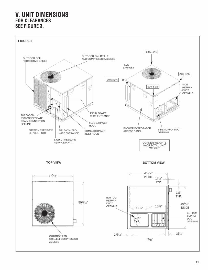
V. UNIT DIMENSIONSFOR CLEARANCESSEE FIGURE 3.
OUTDOOR COILPROTECTIVE GRILLE
OUTDOOR FAN GRILLE AND COMPRESSOR ACCESS
FIELD CONTROL WIRE ENTRANCE
FLUE EXHAUSTHOOD
COMBUSTION AIRINLET HOOD
BOTTOMRETURNDUCTOPENING
BOTTOMSUPPLYDUCTOPENING
OUTDOOR FANGRILLE & COMPRESSOR ACCESS
BLOWER/EVAPORATORACCESS PANEL
SIDE SUPPLY DUCTOPENING
SIDERETURNDUCTOPENING
FLUEEXHAUST
FIELD POWERWIRE ENTRANCE
LIQUID PRESSURESERVICE PORT
THREADEDPVC CONDENSATEDRAIN CONNECTION(3/4 NPT)
SUCTION PRESSURESERVICE PORT
TOP VIEW BOTTOM VIEW
FIGURE 3
479⁄16”
5013⁄16”
313⁄16”
49⁄10”
33⁄16”
497⁄16”INSIDE
11⁄2”TYP.
141⁄4”TYP.
13⁄16”TYP.
451⁄16”INSIDE
191⁄2” 153⁄8”
30% ± 2%
29% ± 2%
20% ± 2%
21% ± 2%
CORNER WEIGHTS% OF TOTAL UNIT
WEIGHT
11

12
FILTER ACCESS PANEL (FOR UNIT MOUNTED FILTERACCESSORY)
SIDE SUPPLY DUCT OPENING
SIDERETURNDUCTOPENING
OUTDOOR COIL PROTECTIVEGRILLE
FLUEEXHAUSTHOOD
GAS SUPPLYENTRANCE
BLOWER/ EVAPORATORACCESS PANEL
SIDE VIEW
FRONT VIEW BACK VIEW
SIDE VIEW
FIGURE 3 (CONTINUED)
MODELS RGEA13/14/15
024, 030, 036, 042
048, 060
“A”HEIGHT
SHOWN WITH DUCT COVERS REMOVED.
207⁄8”
227⁄8”
1315⁄16”75⁄16”
2211⁄16”471⁄2”
3515⁄16”
39⁄16”
3515⁄16”
131⁄4”
21⁄2”
47⁄16”
81⁄2”TYP.
143⁄16”TYP.
133⁄4”TYP.
47⁄8”
191⁄8”15”
41
1015⁄16”
111⁄16”527⁄16”

13
VI. INSTALLATIONA. GENERAL1. PRE-INSTALLATION CHECK-POINTS — Before attempting any installation, care-fully consider the following points:
Structural strength of supporting members(Rooftop Installation)
Clearances and provision for servicingPower supply and wiringGas supply and pipingAir duct connections and sizingDrain facilities and connectionsLocation for minimum noise and vibration
2. LOCATION CONSIDERATIONS (CORROSIVE ENVIRONMENT)
The metal parts of this unit may be subject to rust or deterioration if exposed to acorrosive environment. This oxidation could shorten the equipment’s useful life.Corrosive elements include, but are not limited to, salt spray, fog or mist in seacoastareas, sulphur or chlorine from lawn watering systems, and various chemical conta-minants from industries such as paper mills and petroleum refineries.
If the unit is to be installed in an area where contaminants are likely to be aproblem, give special attention to the equipment location and exposure.
1. Avoid having lawn sprinkler heads spray directly on the unit cabinet.
2. In coastal areas locate the unit on the side of the building away from the water-front.
3. Shielding by a fence or shrubs may give some protection.
1. Frequent washing of the cabinet, fan blade and coil with fresh water will removemost of the salt or other contaminants that build up on the unit.
2. Regular cleaning and waxing of the cabinet with a good automobile polish will pro-vide some protection.
3. Use a good liquid cleaner several times a year to remove matter that will not washoff with water.
Several different types of protective coatings are offered in some areas. These coatingsmay provide some benefit, but the effectiveness of such coating materials cannot be ver-ified by the equipment manufacturer.
The best protection is frequent cleaning, maintenance and minimal exposure tocontaminants.
B. OUTSIDE INSTALLATION
(Typical outdoor slab installation is shown in Figure 4.)
1. Select a location where external water drainage cannot collect around unit.
! WARNINGDISCONNECT ALL POWER TO UNIT BEFORE STARTING MAINTENANCE.FAILURE TO DO SO CAN CAUSE ELECTRICAL SHOCK RESULTING IN PER-SONAL INJURY OR DEATH.
! WARNINGTHESE UNITS ARE DESIGNED CERTIFIED FOR OUTDOOR INSTALLATIONONLY. INSTALLATION INSIDE ANY PART OF A STRUCTURE CAN RESULT ININADEQUATE UNIT PERFORMANCE AS WELL AS PROPERTY DAMAGE.INSTALLATION INSIDE CAN ALSO CAUSE RECIRCULATION OF FLUE PROD-UCTS INTO THE CONDITIONED SPACE RESULTING IN PERSONAL INJURYOR DEATH.

14
2. Provide a slab sufficiently high enough above grade to prevent surface water fromentering the unit. Where snowfall is anticipated, mount the unit above the anticipat-ed maximum snow depth for your area. Do not locate unit in an area where exces-sive snow drifting may block combustion air inlet.
3. Pitch the slab approximately 1⁄2” so that the unit will be pitched toward the drain. SeeFigure 5.
4. The location of the unit should be such as to provide proper access for inspectionand servicing as shown in Figure 11.
5. Locate unit where operating sounds will not disturb owner or neighbors. The slabshould be isolated from the foundation wall.
6. Locate unit so roof runoff water does not pour directly on the unit. Provide gutter orother shielding at roof level.
C. ATTACHING EXHAUST AND COMBUSTION AIR INLET HOODSIMPORTANT: Do not operate this unit without the exhaust and combustion air inlethood properly installed. These hoods are shipped in a carton in the return air compart-ment inside the unit and must be attached when the unit is installed. See Figure 6.
To attach exhaust and combustion air inlet hood:
1. Remove 3 screws securing filter access panel and remove filter access panel. For loca-tion of filter access panel, see Figure 3.
2. Remove both exhaust and combustion air inlet hoods from their carton, located insidethe return air compartment.
3. Attach filter access panel.
4. Attach the combustion air inlet hood and the exhaust hood each with 4 screws as shownin Figure 6. Screws are in parts bag shipped in the burner compartment.
5. Vent the unit using the flue exhaust hood, as supplied from the factory, without alterationor addition. The only exception is with factory approved additions. Consult your local util-ity or other authority having jurisdiction for accepted venting techniques.
FIGURE 4OUTSIDE SLAB INSTALLATION. CLOSET DISTRIBUTION SYSTEM. SLAB FLOORCONSTRUCTION

15
D. COVER PANEL INSTALLATION/CONVERSION PROCEDURE1. HORIZONTAL TO DOWNFLOW
a. Remove screws and covers from the supply and return bottom sections. NOTE:Rotate the supply cover 90° and remove.
b. Install gasket (supplied with parts bag) around perimeter of cover on the insulatedside. See Figure 8.
c. Secure covers to the side of the unit using existing screws and those supplied inthe parts bag.
2. DOWNFLOW TO HORIZONTAL
a. Remove screws and covers from the supply and return bottom sections.
b. Install gasket (supplied with parts bag) around perimeter of cover as illustrated inFigure 7.
c. Install covers in the unit bottom with the insulated side up. NOTE: Supply covermust be inserted through supply opening with narrow side toward unit. Oncecover is through opening, rotate 90° and slip back flange of cover under tab at theback of bottom duct opening. See Figure 10.
d. Secure supply cover to base of unit with 2 screws, engaging prepunched holes inraised duct opening flange.
e. Secure return covers to base of unit with screws engaging prepunched holes inraised duct opening flange.
E.CLEARANCESThe following minimum clearances must be observed for proper unit performance andserviceability. See Figure 11.
1. Provide 48” minimum clearance at front of the unit. Provide 24” minimum clearanceon right side of unit. If economizer is used, a 24” minimum clearance is required on
EXHAUSTHOOD W/(4)SCREWS
COMBUSTIONAIR INLETHOOD W/(4)SCREWS
! WARNINGTHIS UNIT MUST NOT BE INSTALLED DIRECTLY ON WOOD FLOORING, CLASSA, CLASS B OR CLASS C ROOF COVERING MATERIALS, OR ANY OTHER COM-BUSTIBLE STRUCTURE EXCEPT AS SPECIFIED IN FIGURE 15. FAILURE TOADHERE TO THIS WARNING CAN CAUSE A FIRE OR EXPLOSION RESULTINGIN PROPERTY DAMAGE, PERSONAL INJURY OR DEATH.
FIGURE 5PITCHING UNIT TO INSURE PROPER CONDENSATE DRAINAGE.
I655
FIGURE 6COMBUSTION AIR INLET HOOD & EXHAUST HOODINSTALLATION

16
FIGURE 5COVER GASKET DETAIL FOR UNITS SHIPPED FOR DOWNFLOWAPPLICATION BEING CONVERTED TO SIDE DISCHARGE
TAPEAROUND FLANGE
SUPPLY/RETURNAIR COVER
FIGURE 6COVER GASKET DETAIL FOR UNITS SHIPPED FOR SIDE DISCHARGEAPPLICATION BEING CONVERTED TO DOWNFLOW
TAPEAROUND FLANGE
SUPPLY/RETURNAIR COVER
I654
FIGURE 7DUCT COVER INSTALLATION SIDE MOUNTING
I264
RETURNDUCT COVER
(ATTACH WITH 6 SCREWS)
SUPPLYDUCT COVER
(ATTACH WITH 6 SCREWS)
I
FIGURE 8DUCT COVER INSTALLATION BASE PAN MOUNTING
I265
BASE PAN
SUPPLY DUCTCOVER *(INSULATIONSIDE UP),ATTACH WITHTWO SCREWS.
RETURNDUCTCOVER(INSULATIONSIDE UP,ATTACHWITH 4SCREWS)
SUPPLY DUCTCOVER
*ROTATE SUPPLY COVER 90° AFTER IT IS INSERTEDTHROUGH OPENING. SLIP FLANGE OF COVERUNDER LANCE AT BACK OF BOTTOM SUPPLY DUCTOPENING. SEE DETAIL AT LEFT. THEN SECURECOVER BY INSTALLING 2 SCREWS USING HOLENEAREST THE OUTSIDE OF UNIT.
LANCE AT BACK OF BOTTOMSUPPLY DUCT OPENING
FIGURE 7COVER GASKET DETAIL FOR UNITS SHIPPED FOR DOWNFLOWAPPLICATION BEING CONVERTED TO SIDE DISCHARGE
FIGURE 8COVER GASKET DETAIL FOR UNITS SHIPPED FOR SIDE DISCHARGEAPPLICATION BEING CONVERTED TO DOWNFLOW
FIGURE 9DUCT COVER INSTALLATION SIDE MOUNTING
FIGURE 10DUCT COVER INSTALLATION BASE PAN MOUNTING
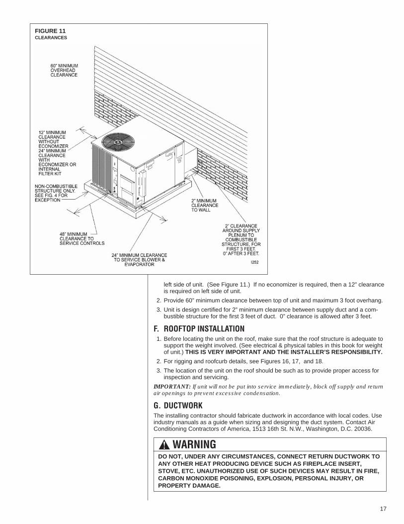
left side of unit. (See Figure 11.) If no economizer is required, then a 12” clearanceis required on left side of unit.
2. Provide 60” minimum clearance between top of unit and maximum 3 foot overhang.
3. Unit is design certified for 2” minimum clearance between supply duct and a com-bustible structure for the first 3 feet of duct. 0” clearance is allowed after 3 feet.
F. ROOFTOP INSTALLATION1. Before locating the unit on the roof, make sure that the roof structure is adequate tosupport the weight involved. (See electrical & physical tables in this book for weightof unit.) THIS IS VERY IMPORTANT AND THE INSTALLER’S RESPONSIBILITY.
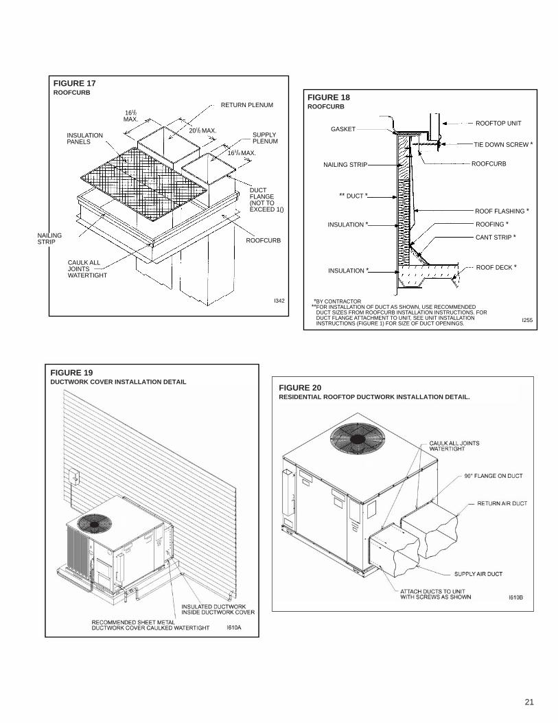
2. For rigging and roofcurb details, see Figures 16, 17, and 18.
3. The location of the unit on the roof should be such as to provide proper access forinspection and servicing.
IMPORTANT: If unit will not be put into service immediately, block off supply and returnair openings to prevent excessive condensation.
G. DUCTWORKThe installing contractor should fabricate ductwork in accordance with local codes. Useindustry manuals as a guide when sizing and designing the duct system. Contact AirConditioning Contractors of America, 1513 16th St. N.W., Washington, D.C. 20036.
17
! WARNINGDO NOT, UNDER ANY CIRCUMSTANCES, CONNECT RETURN DUCTWORK TOANY OTHER HEAT PRODUCING DEVICE SUCH AS FIREPLACE INSERT,STOVE, ETC. UNAUTHORIZED USE OF SUCH DEVICES MAY RESULT IN FIRE,CARBON MONOXIDE POISONING, EXPLOSION, PERSONAL INJURY, ORPROPERTY DAMAGE.
FIGURE 11CLEARANCES
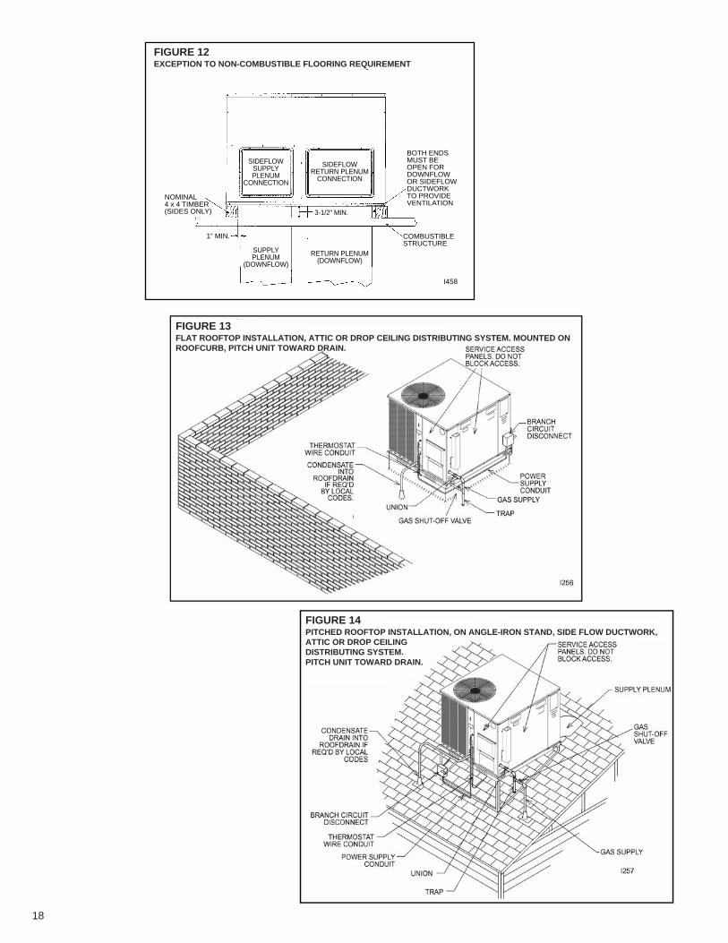
FIGURE 10EXCEPTION TO NON-COMBUSTIBLE FLOORING REQUIREMENT
I458
BOTH ENDSMUST BEOPEN FORDOWNFLOWOR SIDEFLOWDUCTWORKTO PROVIDEVENTILATION
COMBUSTIBLESTRUCTURE
1” MIN.
NOMINAL4 x 4 TIMBER(SIDES ONLY)
SIDEFLOWSUPPLYPLENUM
CONNECTION
SUPPLYPLENUM
(DOWNFLOW)
RETURN PLENUM(DOWNFLOW)
SIDEFLOWRETURN PLENUM
CONNECTION
3-1/2” MIN.
FIGURE 12EXCEPTION TO NON-COMBUSTIBLE FLOORING REQUIREMENT
FIGURE 13FLAT ROOFTOP INSTALLATION, ATTIC OR DROP CEILING DISTRIBUTING SYSTEM. MOUNTED ONROOFCURB, PITCH UNIT TOWARD DRAIN.
FIGURE 14PITCHED ROOFTOP INSTALLATION, ON ANGLE-IRON STAND, SIDE FLOW DUCTWORK,ATTIC OR DROP CEILINGDISTRIBUTING SYSTEM.PITCH UNIT TOWARD DRAIN.
18

Place the unit as close to the conditioned space as possible allowing clearances as indi-cated. Run ducts as directly as possible to supply and return outlets. Use of non-flam-mable weatherproof flexible connectors on both supply and return connections at unit toreduce noise transmission is recommended.
On ductwork exposed to outside temperature and humidity, use a minimum of 2” ofinsulation and a vapor barrier. Distribution system in attic, furred space or crawl spaceshould be insulated with at least 2” of insulation. 1⁄2” to 1” thick insulation is usually suffi-cient for ductwork inside the air conditioned space.
Provide balancing dampers for each branch duct in the supply system. Properly supportductwork from the structure.
IMPORTANT: In the event that the return air ducts must be run through an “unconfined”space containing other fuel burning equipment, it is imperative that the user/homeownermust be informed against future changes in construction which might change this to a“confined space.” Also, caution the user/homeowner against any future installation ofadditional equipment (such as power ventilators, clothes dryers, etc., within the existingunconfined and/or confined space which might create a negative pressure within thevicinity of other solid, liquid, or gas fueled appliances.
H. RETURN AIR
! WARNINGNEVER ALLOW PRODUCTS OF COMBUSTION OR THE FLUE PRODUCTS TOENTER THE RETURN AIR DUCTWORK, OR THE CIRCULATING AIR SUPPLY.ALL RETURN DUCTWORK MUST BE ADEQUATELY SEALED AND SECUREDTO THE FURNACE WITH SHEET METAL SCREWS, AND JOINTS TAPED. ALLOTHER DUCT JOINTS MUST BE SECURED WITH APPROVED CONNECTIONSAND SEALED AIRTIGHT.FAILURE TO PREVENT PRODUCTS OF COMBUSTION FROM BEING CIRCU-LATED INTO THE LIVING SPACE CAN CREATE POTENTIALLY HAZARDOUSCONDITIONS, INCLUDING CAROBON MONOXIDE POISONING THAT COULDRESULT IN PERSONAL INJURY OR DEATH.
FIGURE 15PITCHED ROOFTOP INSTALLATION, ON ROOFJACK, DOWNFLOW DUCTWORK, ATTIC ORDROP CEILING DISTRIBUTING SYSTEM. PITCH UNIT TOWARD DRAIN.
19

I. FILTERSThe installer must install field supplied filters in the return air duct. A field installed filtergrille is recommended for easy and convenient access to the filters for periodic inspec-tion and cleaning. Filters must have adequate face area for the rated air quantity of theunit. See air delivery tables for recommended filter size. A field installed internal filter kitRXRY-B01 is available.
FIGURE 16LIFTING DETAIL
20
I342
I
RETURN PLENUM161/2MAX.
201/2 MAX.
163/8 MAX.
INSULATIONPANELS
NAILINGSTRIP
CAULK ALLJOINTSWATERTIGHT
SUPPLYPLENUM
DUCTFLANGE(NOT TOEXCEED 1()
ROOFCURB
FIGURE 15ROOFCURB
I255
**BY CONTRACTOR**FOR INSTALLATION OF DUCT AS SHOWN, USE RECOMMENDED
DUCT SIZES FROM ROOFCURB INSTALLATION INSTRUCTIONS. FORDUCT FLANGE ATTACHMENT TO UNIT, SEE UNIT INSTALLATIONINSTRUCTIONS (FIGURE 1) FOR SIZE OF DUCT OPENINGS.
ROOFTOP UNIT
TIE DOWN SCREW *
ROOFCURB
ROOF FLASHING *
ROOFING *
CANT STRIP *
ROOF DECK *
GASKET
NAILING STRIP
INSULATION *
INSULATION *
** DUCT *
FIGURE 16ROOFCURB
FIGURE 17ROOFCURB
FIGURE 18ROOFCURB
FIGURE 20RESIDENTIAL ROOFTOP DUCTWORK INSTALLATION DETAIL.
FIGURE 19DUCTWORK COVER INSTALLATION DETAIL
21

VII.GAS SUPPLY, CONDENSATE DRAIN ANDVII.PIPINGA. GAS CONNECTIONIMPORTANT: Connect this unit only to gas supplied by a commercial utility.
1. Install gas piping in accordance with local codes and regulations of the local utilitycompany. In the absence of local codes, the installation must conform to the specifi-cations of the National Fuel Gas Code, ANSI Z223.1 - latest edition.
NOTE: The use of flexible gas connectors is not permitted.
NOTE: The Commonwealth of Massachusetts requires the gas shut-off valve to bea T-handle gas cock.
2. Connect the gas line to the gas pipe inlet opening provided into the 1/2” inlet valve.See Figure 4 for typical piping.
3. Size the gas line to the furnace adequate enough to prevent undue pressure dropand never less than 1/2”.
4. Install a drip leg or sediment trap in the gas supply line as close to the unit as possi-ble.
5. Install an outside ground joint union to connect the gas supply to the control assem-bly at the burner tray.
6. Gas valves have been factory installed. Install a manual gas valve where local codesspecify a shut-off valve outside the unit casing. (See Figure 21.)
7. Make sure piping is tight. A pipe compound resistant to the action of liquefiedpetroleum gases must be used at all threaded pipe connections.
8. IMPORTANT: Any additions, changes or conversions required for the furnace to sat-isfactorily meet the application should be made by a qualified installer, serviceagency or the gas supplier, using factory-specified or approved parts. In the com-monwealth of Massachusetts, installation must be performed by a licensed plumberor gas fitter for appropriate fuel.
IMPORTANT: Disconnect the furnace and its individual shutoff valve from the gas sup-ply piping during any pressure testing of that system at test pressures in excess of 1/2psig or isolate the system from the gas supply piping system by closing its individualmanual shutoff valve during any pressure testing of this gas supply system at pressuresequal to or less than 1/2 PSIG.
FIGURE 19SUGGESTED GAS PIPING
FROM GASMETER
*Factory supplied grommet must be utilized.
MANUAL GASSHUT-OFFVALVE
UNIT GAS SUPPLYCONNECTION *
ROOF OR GROUND LEVEL INSTALLATION
NominalIron Pipe
Size,Inches
Equivalent Length of Pipe, Feet
10 20 30 40 50 60 70 80
1/2 132 92 73 63 56 50 46 433/4 278 190 152 130 115 105 96 901 520 350 285 245 215 195 180 170
11/4 1,050 730 590 500 440 400 370 35011/2 1,600 1,100 890 760 670 610 560 530
TABLE 1GAS PIPE CAPACITY TABLE (CU. FT./HR.)
FIGURE 21SUGGESTED GAS PIPING
22
TO CHECK FOR GAS LEAKS, USE A SOAP AND WATER SOLUTION OR OTHERAPPROVED METHOD. DO NOT USE AN OPEN FLAME.
IMPORTANT: Check the rating plate to make certain the appliance is equipped to burnthe type of gas supplied. Care should be taken after installation of this equipment thatthe gas control valve not be subjected to high gas supply line pressure.
In making gas connections, avoid strains as they may cause noise and damage the con-trols. A backup wrench is required to be used on the valve to avoid damage.
The capacities of gas pipe of different diameters and lengths in cu. ft. per hr. with pres-sure drop of 0.5 in. and specific gravity of 0.60 (natural gas) are shown in Table 2.
After determining the pipe length, select the pipe size which will provide the minimumcubic feet per hour re quired for the gas input rating of the furnace. By formula:
Gas Input of Furnace(BTU/HR)
Cu. Ft. Per Hr. Required =Heating Value of Gas(BTU/FT3)
The gas input of the furnace is marked on the furnace rating plate. The heating value ofthe gas (BTU/FT3) may be determined by consulting the local natural gas utility or theL.P. gas supplier.
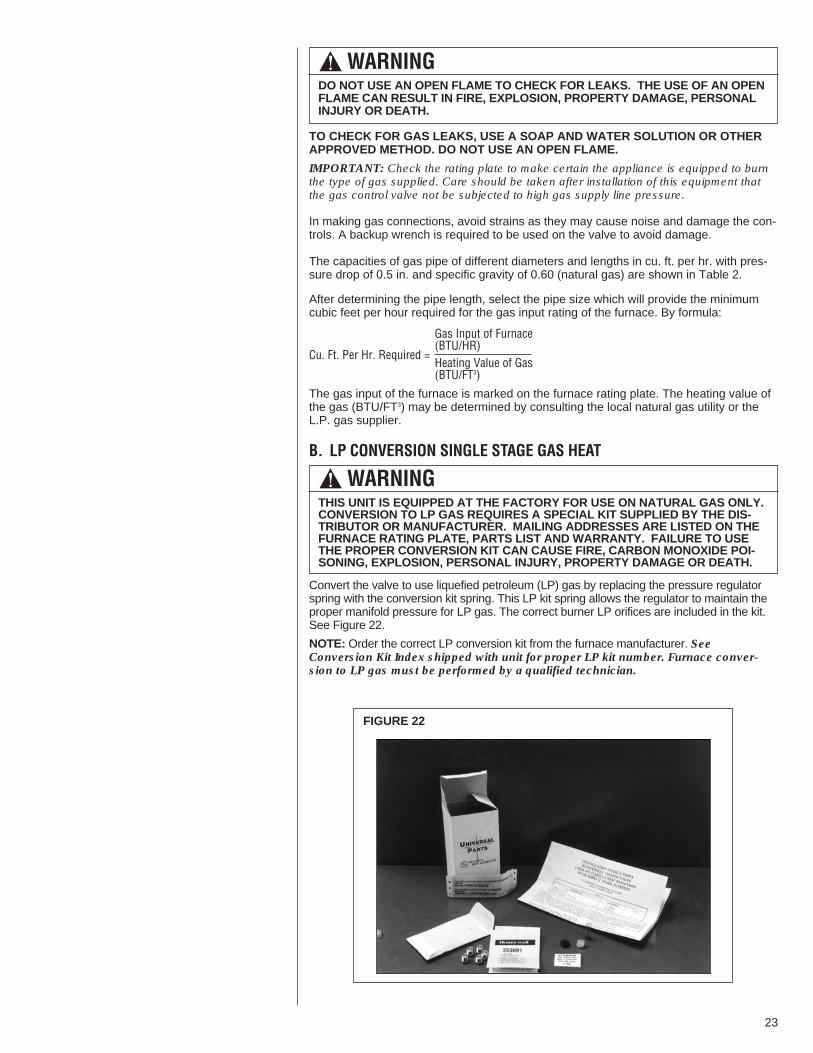
B. LP CONVERSION SINGLE STAGE GAS HEAT
Convert the valve to use liquefied petroleum (LP) gas by replacing the pressure regulatorspring with the conversion kit spring. This LP kit spring allows the regulator to maintain theproper manifold pressure for LP gas. The correct burner LP orifices are included in the kit.See Figure 22.
NOTE: Order the correct LP conversion kit from the furnace manufacturer. SeeConversion Kit Index shipped with unit for proper LP kit number. Furnace conver-sion to LP gas must be performed by a qualified technician.
! WARNINGDO NOT USE AN OPEN FLAME TO CHECK FOR LEAKS. THE USE OF AN OPENFLAME CAN RESULT IN FIRE, EXPLOSION, PROPERTY DAMAGE, PERSONALINJURY OR DEATH.
! WARNINGTHIS UNIT IS EQUIPPED AT THE FACTORY FOR USE ON NATURAL GAS ONLY.CONVERSION TO LP GAS REQUIRES A SPECIAL KIT SUPPLIED BY THE DIS-TRIBUTOR OR MANUFACTURER. MAILING ADDRESSES ARE LISTED ON THEFURNACE RATING PLATE, PARTS LIST AND WARRANTY. FAILURE TO USETHE PROPER CONVERSION KIT CAN CAUSE FIRE, CARBON MONOXIDE POI-SONING, EXPLOSION, PERSONAL INJURY, PROPERTY DAMAGE OR DEATH.
FIGURE 22
23

C. NOx MODELSWhen converting units equipped with NOx inserts to LP gas, the stainless steel meshinserts in the entrance of the tubular exchangers are not required to meet SCAQMD NOxemission levels. Carefully remove these inserts before firing this furnace on LP gas. Thisfurnace is not designed to operate on LP gas with the NOx inserts in place.Step by step instructions on removing the NOx inserts and retaining rod are included in theConversion Kit Installation Instructions.
D. ADJUSTING OR CHECKING FURNACE INPUT– Natural Gas Line Pressure 5” - 10.5” W.C.– LP Gas Line Pressure 11” - 13” W.C.– Natural Gas Manifold Pressure 3.5” W.C– LP Gas Manifold Pressure - 10” W.C.Supply and manifold pressure taps are located on the gas valve body 1/8” N.P.T. Use a properly calibrated manometer gauge for accurate gas pressure readings.Only small variations in the gas flow should be made by means of the pressure regulatoradjustment. Furnaces functioning on LP gas must be set by means of the tank or branchsupply regulators. The furnace manifold pressure should be set at 10” W.C. at the gas con-trol valve.To adjust the pressure regulator, remove the regulator cap and turn the adjustment screwclockwise to increase pressure or counterclockwise to decrease pressure. Then replacethe regulator cap securely.Any necessary major changes in the gas flow rate should be made by changing the size ofthe burner orifices. To change orifice spuds, shut off the manual main gas valve andremove the gas manifold.For elevations up to 2,000 feet, rating plate input ratings apply. For high altitudes (elevationsover 2,000 ft.), see conversion kit index 92-21519-47 for derating and orifice spud sizes.Check of input is important to prevent over-firing of the furnace beyond its design-rated input. NEVER SET INPUT ABOVE THAT SHOWN ON THE RATING PLATE. Usethe following table or formula to determine input rate.
Heating Value of Gas(BTU/Cu. Ft.) x 3600
Cu. Ft. Per Hr. Required =Time in Seconds(for 1 Cu. Ft.) of Gas
Maximum capacity of pipe in thousands of BTU per hour of undiluted liquefied petroleumgases (at 11 inches water column inlet pressure).(Based on a Pressure Drop of 0.5 Inch Water Column)
TABLE 2LP GAS PIPE CAPACITY TABLE (CU. FT./HR.)
NominalIron PipeSize, Inches 10 20 30 40 50 60 70 80 90 100 125 150
275 189 152 129 114 103 96 89 83 78 69 63567 393 315 267 237 217 196 182 173 162 146 132
1,071 732 590 504 448 409 378 346 322 307 275 2522,205 1,496 1,212 1,039 913 834 771 724 677 630 567 5113,307 2,299 1,858 1,559 1,417 1,275 1,181 1,086 1,023 976 866 7876,221 4,331 3,465 2,992 2,646 2,394 2,205 2,047 1,921 1,811 1,606 1,496
1/23/41
1-1/41-1/2
2
Length of Pipe, Feet
Example (LP): Input BTU requirement of unit, 150,000Equivalent length of pipe, 60 ft. = 3/4” IPS required.
24

Start the furnace and measure the time required to burn one cubic foot of gas. Prior tochecking the furnace input, make certain that all other gas appliances are shut off, withthe exception of pilot burners. Time the meter with only the furnace in operation.
IMPORTANT NOTE FOR ALTITUDES ABOVE 2,000 FEET (610 METERS): The mainburner orifices in your furnace and in these kits are sized for the nameplate input andintended for installations at elevations up to 2,000 feet in the USA or Canada, or for ele-vations of 2,000 - 4,500 feet (610 -1,373 meters) in Canada if the unit has been deratedat the factory. For elevations above 2,000 feet (610 meters) IN THE USA ONLY (seeANSI-Z223.1), the burner orifices must be sized to reduce the input 4% for each 1,000feet (305 meters) above sea level.
NOTICE: DERATING OF THE HEATING INPUT FOR HIGH ALTITUDE IN THE FIELDIS UNLAWFUL IN CANADA (REFER TO CAN/CGA 2.17). UNITS INSTALLED INALTITUDES GREATER THAN 2,000 FEET (610 METERS) MUST BE SHIPPED FROMTHE FACTORY OR FROM A FACTORY AUTHORIZED CONVERSION STATIONWITH THE HEATING INPUT DERATED BY 10% SO AS TO OPERATE PROPERLY INALTITUDES FROM 2,000 - 4,500 FEET (610 - 1,373 METERS).
E. CONDENSATE DRAINThe evaporator coil condensate drain ends with a threaded 3/4” nominal PVC stub. Atrap is built in for proper condensate drainage and to prevent debris from being drawninto the unit. Do not connect the drain to a closed sewer line. Connection to a ventedsewer line is allowed. It is recommended that a PVC cement not be used so that thedrain line can be easily cleaned in the future.
IMPORTANT: DO NOT INSTALL AN EXTERNAL TRAP. DOING SO CAN CAUSEIMPROPER DRAINAGE OF THE CONDENSATE AND RESULT IN FLOODING WITH-IN THE UNIT.
VIII.WIRINGA. POWER SUPPLY
! WARNINGTURN OFF THE MAIN ELECTRICAL POWER AT THE BRANCH CIRCUIT DISCON-NECT CLOSEST TO THE UNIT BEFORE ATTEMPTING ANY WIRING. FAILURETO DO SO CAN CAUSE ELECTRICAL SHOCK RESULTING IN PERSONALINJURY OR DEATH.
ONE 1 21 1 30 1 34 1 39 3 4540,000TEN 13 30 15 0 15 36 16 30 37 30
ONE 0 54 1 0 1 3 1 6 2 3060,000TEN 9 0 10 0 10 24 11 0 25 0
ONE 0 41 0 45 0 47 0 50 1 5380,000TEN 6 45 7 30 7 48 8 15 18 45
ONE 0 33 0 36 0 38 0 40 1 30100,000TEN 5 24 6 0 6 15 6 36 15 0
METER TIME IN MINUTES AND SECONDS FOR NORMALINPUT RATING OF FURNACES EQUIPPED FOR NATURAL
OR LP GAS
INPUTBTU/HR
METERSIZE
CU. FT.
HEATING VALUE OF GAS BTU PER CU. FT.900 1000 1040 1100 2500
MIN. SEC. MIN. SEC. MIN. SEC. MIN. SEC. MIN. SEC.
TABLE 3
25
1. All wiring should be made in accordance with the National Electrical Code.Consult the local power company to determine the availability of sufficient power tooperate the unit. Check the voltage at power supply to make sure it corresponds tothe unit’s RATED VOLTAGE REQUIREMENT. Install a branch circuit disconnectnear the rooftop, in accordance with the N.E.C., C.E.C. or local codes.
2. It is important that proper electrical power is available at the unit. Voltage should notvary more than 10% from that stamped on the unit nameplate. On three phase units,phases must be balanced within 3%.
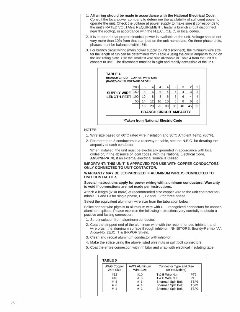
3. For branch circuit wiring (main power supply to unit disconnect), the minimum wire sizefor the length of run can be determined from Table 4 using the circuit ampacity found onthe unit rating plate. Use the smallest wire size allowable in Table 4 from the unit dis-connect to unit. The disconnect must be in sight and readily accessible of the unit.
NOTES:
1. Wire size based on 60°C rated wire insulation and 30°C Ambient Temp. (86°F).
2. For more than 3 conductors in a raceway or cable, see the N.E.C. for derating theampacity of each conductor.
When installed, the unit must be electrically grounded in accordance with localcodes or, in the absence of local codes, with the National Electrical Code,ANSI/NFPA 70, if an external electrical source is utilized.
IMPORTANT: THIS UNIT IS AP PROVED FOR USE WITH COPPER CONDUCTORSONLY CONNECTED TO UNIT CONTACTOR.
WARRANTY MAY BE JEOPARDIZED IF ALUMINUM WIRE IS CONNECTED TOUNIT CONTACTOR.
Special instructions apply for power wiring with aluminum conductors: Warrantyis void if connections are not made per instructions.
Attach a length (6” or more) of recommended size copper wire to the unit contactor ter-minals L1 and L3 for single phase, L1, L2 and L3 for three phase.
Select the equivalent aluminum wire size from the tabulation below:
Splice copper wire pigtails to aluminum wire with U.L. recognized connectors for copper-aluminum splices. Please exercise the following instructions very carefully to obtain apositive and lasting connection:1. Strip insulation from aluminum conductor.2. Coat the stripped end of the aluminum wire with the recommended inhibitor, andwire brush the aluminum surface through inhibitor. INHIBITORS: Brundy-Pentex “A”;Alcoa-No. 2EJC; T & B-KPOR Shield.
3. Clean and recoat aluminum conductor with inhibitor.4. Make the splice using the above listed wire nuts or split bolt connectors.5. Coat the entire connection with inhibitor and wrap with electrical insulating tape.
200 6 4 4 4 3 3 2 2
150 8 6 6 4 4 4 3 3
100 10 8 8 6 6 6 4 4
50 14 12 10 10 8 8 6 6
15 20 25 30 35 40 45 50
TABLE 4BRANCH CIRCUIT COPPER WIRE SIZE(BASED ON 1% VOLTAGE DROP)*
SUPPLY WIRELENGTH-FEET
*Taken from National Electric Code
BRANCH CIRCUIT AMPACITY
AWG Copper AWG Aluminum Connector Type and SizeWire Size Wire Size (or equivalent)
#12 #10 T & B Wire Nut PT2#10 # 8 T & B Wire Nut PT3# 8 # 6 Sherman Split Bolt TSP6# 6 # 4 Sherman Split Bolt TSP4# 4 # 2 Sherman Split Bolt TSP2
TABLE 5
26

B. HOOK-UPTo wire unit, refer to the following hook-up diagram (see Figure 23).Refer to Figure 3 for location of wiring entrances.Wiring to be done in the field between the unit and devices not attached to the unit, orbetween separate devices which are field installed and located, shall conform with thetemperature limitation for Type T wire [63°F rise (35°C)] when installed in accordancewith the manufacturer’s instructions.
C. INTERNAL WIRINGIMPORTANT: Some single phase units are equipped with a single pole contactor.Caution must be exercised when servicing as only one leg of the power supply is brokenwith the contactor.A diagram of the internal wiring of this unit is located under the electrical box cover andin this manual. If any of the original wire as supplied with the appliance must bereplaced, the wire gauge and insulation must be same as original wiring.Transformer is factory wired for 230 volts on 208/230 volt models and must be changedfor 208 volt applications. See unit wiring diagram for 208 volt wiring.
D. THERMOSTATThe room thermostat must be compatible with the spark ignition control on the unit.Generally, all thermostats that are not of the “current robbing” type are compatible withthe integrated furnace control. Two stage units (5 ton) require use of a thermostat capa-ble of 2 stages of cooling. (See Section IV.) See chart below for recommendations. Thelow voltage wiring should be sized as shown in Table 6.
Install the room thermostat in accordance with the instruction sheet packed in the boxwith the thermostat. Never install the thermostat on an outside wall or where it will beinfluenced by drafts, concealed hot or cold water pipes or ducts, lighting fixtures, radia-tion from fireplace, sun rays, lamps, televisions, radios or air streams from registers.Refer to instructions packed with the thermostat for “heater” selection or adjustment.
Refer to the RGEA13/14/15 Specification Sheets for a list of recommended thermostats.
FOR INTERNAL WIRING SEE WIRING LABEL ATTACHED TO UNIT
*T1
T2
T3
L1
L2
L3
CONTACTOR
HIGH VOLTAGEDISCONNECTSWITCH
CHASSIS GROUND
THERMOSTAT
Y - COOLING (LOW STAGE IN 2 STAGE SYSTEMS)G - FAN ONLYR - 24VW - HEATING (LOW HEAT 2 STAGE GAS HEAT)C - COMMONY2 - HIGH STAGE COOLING (TWO STAGE ONLY)L - ALERT CODES (OPTIONAL WITH COMFORT ALERTL - AND COMPATIBLE THERMOSTAT)
*L2 connection 3Phase only
LOW VOLTAGEWIRE LEADS
Y G R W C Y2 L
Y G R W C Y2 L
FIGURE 23WIRE HOOK-UP DIAGRAM
27

IX. FURNACE SECTION CONTROLS ANDIGNITION SYSTEM
A. NORMAL FURNACE OPERATING SEQUENCE (SINGLE STAGE GAS HEAT)This unit is equipped with an integrated direct spark ignition control.1. The thermostat calls for heat.2. The control board will run a self check to verify that the limit control and manual resetovertemperature control are closed and that the pressure switch is open. If so, theinduced draft blower (inducer) begins a prepurge cycle.
3. The air proving negative pressure switch closes.4. 15 seconds after the pressure switch closes, the gas valve opens and the spark isinitiated for a 7 second trial for ignition.
5. Burners ignite and flame sensor proves all burners have lit.6. The circulating air blower is energized after 20 seconds.7. The control board enters a normal operation loop in which all safety controls are moni-tored continuously.
8. Thermostat is satisfied and opens.9. The gas valve is de-energized and closes, shutting down the burner flame.10. The control board will de-energize the inducer after a five second post purge.11. The circulating air blower is de-energized after 180 seconds.• The integrated control board has a three ignition system.• After a total of three trials for ignition without sensing main burner flame, the systemgoes into a 100% lockout mode.
• After one hour, the ignition control repeats the prepurge and ignition cycles for 3 triesand then goes into 100% lockout mode again.
• It continues this sequence of cycles and lockout each hour until ignition is successful orpower is interrupted.
• During the lockout mode, neither the spark ignition control or gas valve will be energizeduntil the system is reset by turning the thermostat to the “OFF” position or interruptingthe electrical power to the unit for 3 seconds or longer.
• The induced draft blower and main burner will shut off when the thermostat is satisfied.• The circulating air blower will start and run on the heating speed if the thermostat fanswitch is in the “ON” position.
The integrated furnace control is equipped with diagnostic LED. The LED is lit continuouslywhen there is power to the control, with or without a call for heat. If the LED is not lit, thereis either no power to the control or there is an internal component failure within the control,and the control should be replaced.If the control detects the following failures, the LED will flash on for approximately 1/4 sec-ond, then off for 3/4 second for designated failure detections.1 Flash: Failed to detect flame within the three tries for ignition.2 Flash: Pressure switch or induced draft blower problem detected.3 Flash: High limit or auxiliary limit open.4 Flash: Flame sensed and gas valve not energized or flame sensed with no “W” signal.5 Flash: Overtemperature switch open.
FIELD WIRE SIZE FOR 24 VOLT THERMOSTAT CIRCUITS
SOLID COPPER WIRE - AWG.
3.0 16 14 12 10 10 102.5 16 14 12 12 12 102.0 18 16 14 12 12 10
50 100 150 200 250 300Length of Run – Feet (1)T
her
mo
stat
Lo
ad -
Am
ps
TABLE 6
(1) The total wire length is the distance from the furnace to thethermostat and back to the furnace.NOTE: DO NOT USE CONTROL WIRING SMALLER THAN NO. 18AWG.
TABLE 6
28
B. OPERATING INSTRUCTIONSThis appliance is equipped with a direct spark intermittent ignition device. This devicelights the main burners each time the room thermostat (closes) calls for heat. See operat-ing instructions on the back of the furnace/controls access panel.
TO START THE FURNACE1. STOP! Read the safety information on the Operating Instructions Label located on thisappliance.
2. Set the thermostat to its lowest setting.3. Turn off all electric power to the appliance.4. This appliance does not have a pilot. It is equipped with an ignition device which auto-matically lights the burner. Do NOT try to light the burner by hand.
5. Remove control door/access panel.6. Move switch to the “OFF” position.7. Wait five (5) minutes to clear out any gas. Then smell for gas, including near the floor.If you smell gas, STOP!• Do not try to light any appliance.• Do not touch any electric switch; do not use any phone in your building.• Immediately call your gas supplier from a neighbor’s phone. Follow the gas supplier’s• instructions.• If you cannot reach your gas supplier, call the fire department.If you don’t smell gas, go to the next step.
8. Move the switch from “OFF” position to “ON” position.9. Replace the control door.10. Turn on all electric power to the appliance.11. Set the thermostat to the desired setting.12. If the appliance will not operate, follow the instructions below on how to shut down the
furnace.
The initial start-up on a new installation may require the control system to be energized forsome time until any air has bled through the system and fuel gas is available at the burn-ers.
TO SHUT DOWN FURNACE1. Set the thermostat to the lowest setting.2. Turn off all electric power to the appliance if service is to be performed.3. Remove control door.4. Move switch to the “OFF” position.5. Replace control door.
29
! WARNINGTHE SPARK IGNITOR AND IGNITION LEAD FROM THE IGNITION CONTROLARE HIGH VOLTAGE. KEEP HANDS OR TOOLS AWAY TO PREVENT ELEC-TRICAL SHOCK. SHUT OFF ELECTRICAL POWER BEFORE SERVICING ANYOF THE CONTROLS. FAILURE TO ADHERE TO THIS WARNING CAN RESULTIN PERSONAL INJURY OR DEATH.
! WARNINGDO NOT ATTEMPT TO MANUALLY LIGHT THIS FURNACE WITH A MATCH ORANY OPEN FLAME. ATTEMPTING TO DO SO CAN CAUSE AN EXPLOSION ORFIRE RESULTING IN PROPERTY DAMAGE, PERSONAL INJURY OR DEATH.
! WARNINGIF YOU DO NOT FOLLOW THESE INSTRUCTIONS EXACTLY, A FIRE OREXPLOSION MAY RESULT CAUSING PROPERTY DAMAGE, PERSONALINJURY OR LOSS OF LIFE.

C. BURNERSBurners for these units have been designed so that field adjustment is not required.Burners are tray-mounted and accessible for easy cleaning when required.
D. MANUAL RESET OVERTEMPERATURE CONTROLA manual reset overtemperature control is located on the burner shield. This device sens-es blockage in the heat exchanger or insufficient combustion air. This shuts off the mainburners if excessive temperatures occur in the burner compartment.Operation of this control indicates an abnormal condition. Therefore, the unit should beexamined by a qualified installer, service agency, or the gas supplier before being placedback into operation.
E. PRESSURE SWITCH(S)This furnace has pressure switches for sensing a blocked exhaust or a failed induced draftblower. They’re normally open and close when the induced draft blower starts, indicatingair flow through the combustion chamber.
F. LIMIT CONTROLThe supply air high temperature limit cut-off is set at the factory and cannot be adjusted. Itis calibrated to prevent the air temperature leaving the furnace from exceeding the maxi-mum outlet air temperature. WARNING: DO NOT JUMPER THIS DEVICE! Replacethis control only with the identical replacement part.
X. SYSTEM OPERATING INFORMATIONA. ADVISE THE CUSTOMER1. Keep the air filters clean. The heating system operates better, more efficiently andmore economically.
2. Arrange the furniture and drapes so that the supply air registers and the return airgrilles are unobstructed.
3. Close doors and windows. This reduces the heating load on the system.4. Avoid excessive use of exhaust fans.5. Do not permit the heat generated by television, lamps or radios to influence the ther-mostat operation.
6. Except for the mounting platform, keep all combustible articles three feet from the unitand exhaust system.
7. IMPORTANT: Replace all blower doors and compartment cover after servicing theunit. Do not operate the unit without all panels and doors securely in place.
8. Do not allow snow or other debris to accumulate in the vicinity of the appliance.
B. FURNACE SECTION MAINTENANCEThe unit’s furnace should operate for many years without excessive scale build-up in fluepassageways; however, it is recommended that a qualified installer, service agency, or thegas supplier annually inspect the flue passageways, the exhaust system and the burnersfor continued safe operation, paying particular attention to deterioration from corrosion orother sources.If during inspection the flue passageways and exhaust system are determined to requirecleaning, the following procedures should be followed (by a qualified installer, serviceagency, or gas supplier):
! WARNINGSHOULD OVERHEATING OCCUR OR THE GAS SUPPLY FAIL TO SHUT OFF,SHUT OFF THE MANUAL GAS VALVE TO THE APPLIANCE BEFORE SHUT-TING OFF THE ELECTRICAL SUPPLY. FAILURE TO DO SO CAN RESULT INAN EXPLOSION OR FIRE CAUSING PROPERTY DAMAGE, SEVERE PERSON-AL INJURY OR DEATH!
! WARNINGDO NOT JUMPER THIS DEVICE! DO NOT reset the overtemperature controlwithout taking corrective action to assure that an adequate supply of combus-tion air is maintained under all conditions of operation. Failure to do so canresult in carbon monoxide poisoning or death. Replace this control only withthe identical replacement part.
30
1. Turn off the electrical power to the unit and set the thermostat to the lowest tem-perature.
2. Shut off the gas supply to the unit either at the meter or at manual valve in thesupply piping.
3. Remove the furnace controls access panel and the control box cover.4. Disconnect the gas supply piping from the gas valve.5. Disconnect the wiring to the induced draft blower motor, gas valve, flame sensor, andflame roll-out control, and ignitor cable. Mark all wires disconnected for properreconnection.
6. Remove the screws (4) connecting the burner tray to the heat exchanger mountingpanel.
7. Remove the burner tray and the manifold assembly from the unit.8. Remove the screws (4) connecting the induced draft blower to the collector box andscrews (16) connecting the collector box to the heat exchanger mounting panel.Remove the induced draft blower and the collector box from the unit.
9. Remove the turbulators from inside the heat exchangers by inserting the blade of ascrewdriver under the locking tabs. Pop the tabs out of the expanded grooves of theheat exchanger. Slide the turbulators out of the heat exchangers.
10. Direct a water hose into the outlet of the heat exchanger top. Flush the inside of eachheat exchanger tube with water. Blow out each tube with air to remove excessivemoisture.
11. Reassemble (steps 1 through 10 in reverse order). Be careful not to strip out thescrew holes used to mount the collector box and inducer blower. Replace induc-er blower gasket and collector box gasket with factory replacements if dam-aged.
The manufacturer recommends that a qualified installer, service agency or the gas suppli-er visually inspect the burner flames for the desired flame appearance at the beginning ofthe heating season and approximately midway in heating season.The manufacturer also recommends that a qualified installer, service agency or the gassupplier clean the flame sensor with steel wool at the beginning of the heating season.
C. LUBRICATIONIMPORTANT: DO NOT attempt to lubricate the bearings on the blower motor or theinduced draft blower motor. Addition of lubricants can reduce the motor life and void thewarranty.The blower motor and induced draft blower motor are prelubricated by the manufacturerand do not require further attention.A qualified installer, service agency or the gas supplier must periodically clean themotors to prevent the possibility of overheating due to an accumulation of dust and dirton the windings or on the motor exterior. And, as suggested elsewhere in these instruc-tions, the air filters should be kept clean because dirty filters can restrict air flow and themotor depends upon sufficient air flowing across and through it to prevent overheating.
31
! WARNINGLABEL ALL WIRES PRIOR TO DISCONNECTION WHEN SERVICING CON-TROLS. WIRING ERRORS CAN CAUSE IMPROPER AND DANGEROUS OPER-ATION RESULTING IN FIRE, ELECTRICAL SHOCK, PROPERTY DAMAGE, PER-SONAL INJURY OR DEATH.
! WARNINGHOLES IN THE EXHAUST TRANSITION OR HEAT EXCHANGER CAN CAUSETOXIC FUMES TO ENTER THE HOME. THE EXHAUST TRANSITION OR HEATEXCHANGER MUST BE REPLACED IF THEY HAVE HOLES OR CRACKS INTHEM. FAILURE TO DO SO CAN CAUSE CARBON MONOXIDE POISONINGRESULTING IN PERSONAL NJURY OR DEATH.
! WARNINGDISCONNECT MAIN ELECTRICAL POWER TO THE UNIT BEFORE ATTEMPT-ING MAINTENANCE. FAILURE TO DO SO MAY RESULT IN ELECTRICALSHOCK OR SEVERE PERSONAL INJURY OR DEATH.

D. COOLING SECTION MAINTENANCE
It is recommended that at the beginning of each cooling season a qualified installer orservice agency inspect and clean the cooling section of this unit. The following areasshould be addressed: evaporator coil, condenser coil, condenser fan motor and venturiarea.
To inspect the evaporator coil:
1. Remove the filter access panel and the blower/evaporator coil access panel.
2. Unplug the wires from the circulating air blower and the limit control. Remove thetwo screws and slide the blower out of the unit sideways.
3. Shine a flashlight on the evaporator coil (both sides) and inspect for accumulation oflint, insulation, etc.
4. If coil requires cleaning, follow the steps shown below.
Cleaning Evaporator Coil1. Remove screws from condenser fan grille assembly and lay grille over on the unittop panel.
2. Remove the controls access panel and the control box cover.3. Disconnect the outdoor fan motor wiring from the compressor contactor and capaci-tor. Remove the strain relief in the bulkhead and pull the fan motor wires through.Set grille assembly to the side.
4. Remove the screws that secure the unit top to the unit. Remove the top and set theunit top to the side.
5. The coil should be cleaned when it is dry. If the coil is coated with dirt or lint, vacu-um it with a soft brush attachment. Be careful not to bend the coil fins.
6. If the coil is coated with oil or grease, clean it with water or Ph neutral cleaner solu-tion. Rinse the coil thoroughly with water. IMPORTANT: Do not use excessive waterpressure. Excessive water pressure can bend the fins and tubing of the coil and leadto inadequate unit performance. Be careful not to splash water excessively into unit.
7. Go to next section for cleaning the condenser coil.Cleaning Condenser Coil, Drain Pan, Condensate Drain, Condenser Fan,Circulation Air Blower and Venturi1. Remove the screws from the condenser coil protective grille and remove the grillefrom the unit. Ensure the filter access panel is still removed to access all of thescrews securing the grille.
2. The coil should be cleaned when it is dry. If the coil is coated with dirt or lint, vacuumit with a soft brush attachment. Be careful not to bend the coil fins.
3. If the coil is coated with oil or grease, clean it with water or Ph neutral cleaner solu-tion. Rinse the coil thoroughly with water. IMPORTANT: Do not use excessive waterpressure. Excessive water pressure can bend the fins and tubing of the coil and leadto inadequate unit performance. Be careful not to splash water excessively into unit.
4. Inspect the drain pan and condensate drain at the same time the condenser coil ischecked. Clean the drain pan by flushing with water and removing any matters ofobstructions which may be present.
5. Flush the drain tube with water. If the drain tube is blocked, it can usually be clearedwth high pressure water.
6. Inspect the circulating air blower wheel and motor for accumulation of lint, dirt orother obstruction and clean if necessary. Inspect the blower motor mounts and theblower housing for loose mounts or other damage. Repair or replace if necessary.
Re-assembly1. Place the condenser coil protective grille back on unit and replace all screws.2. Place top panel back on unit and replace all screws.3. Set condenser fan grille assembly on top of the unit with the fan on top and themotor wires on the venturi side. Run the fan motor wires through the bulkhead and
! WARNINGLABEL ALL WIRES PRIOR TO DISCONNECTION WHEN SERVICING THE UNIT.WIRING ERRORS CAN CAUSE IMPROPER AND DANGEROUS OPERATIONRESULTING IN FIRE, ELECTRICAL SHOCK, PROPERTY DAMAGE, SEVEREPERSONAL INJURY OR DEATH.
! WARNINGDISCONNECT MAIN ELECTRICAL POWER TO THE UNIT BEFORE ATTEMPT-ING MAINTENANCE. FAILURE TO DO SO MAY RESULT IN ELECTRICALSHOCK OR SEVERE PERSONAL INJURY OR DEATH.
32

pull wires through the hole on the bottom of the control box on the left side and intothe control box. Reconnect fan motor wires per the wiring diagram attached to theback of the control box cover.
4. Replace wire strain relief in bulkhead after the slack is pulled out of the wires on thefan side. This will assure wires will not be damaged by the fan during unit operation.
5. Turn the condenser fan grille assembly over and into the recess in the unit top.Secure the grille to the unit with the four screws removed earlier.
6. Replace the circulating air blower, making sure that all wires are properly reconnect-ed per the unit wiring diagram.
7. Replace the filter and blower/evaporator coil access panels.8. Replace the control box cover and controls access panel.9. Restore electrical power to the unit and check for proper operation, especially thecondenser fan motor.
E. REPLACEMENT PARTSContact your local distributor for a complete parts list.
F. CHARGINGRefer to the appropriate charge chart included in this manual.
G. BLOWER MOTOR SPEED ADJUSTMENTS
Note: These instructions to be used in conjunction with airflow data tables.After determining necessary CFM and speed tap, follow the steps below to changespeeds.
Units with PSC Blower Motors:1. Remove the furnace/control access panel.2. Remove the control box cover. See Figure 24 for location of the furnace controlboard.
3. Reference Figure 25 for the proper location of the wires on the speed tap block andon the furnace control board to obtain the speed tap you have chosen.Note: 460V units have dedicated heating and cooling speeds and should not beadjusted.
4. After adjusting the wires accordingly, attach the control box cover, furnace controlaccess panel and the blower access panel to the unit.
Units with X-13 Motors1. Remove blower access panel.2. Locate wire terminals on the motor. Numbered terminals are 24V blower taps (Seeairflow tables for corresponding speed). The C terminal is 24V common. L, N, and Gterminals are high voltage and must remain unchanged.
3. Cooling speeds can be adjusted as noted in Figure 25 by moving appropriate wirebetween taps at the blower (Do not connect wires to unspecified speed taps).Note: Heat speed is dedicated and should not be changed. The first stage coolingspeed on 5-ton models is dedicated and should not be changed.
4. Replace blower access panel.
33
! WARNINGDISCONNECT MAIN ELECTRICAL POWER TO THE UNIT BEFORE ATTEMPT-ING TO CHANGE BLOWER SPEEDS. FAILURE TO DO SO MAY RESULT INELECTRICAL SHOCK OR SEVERE PERSONAL INJURY OR DEATH.
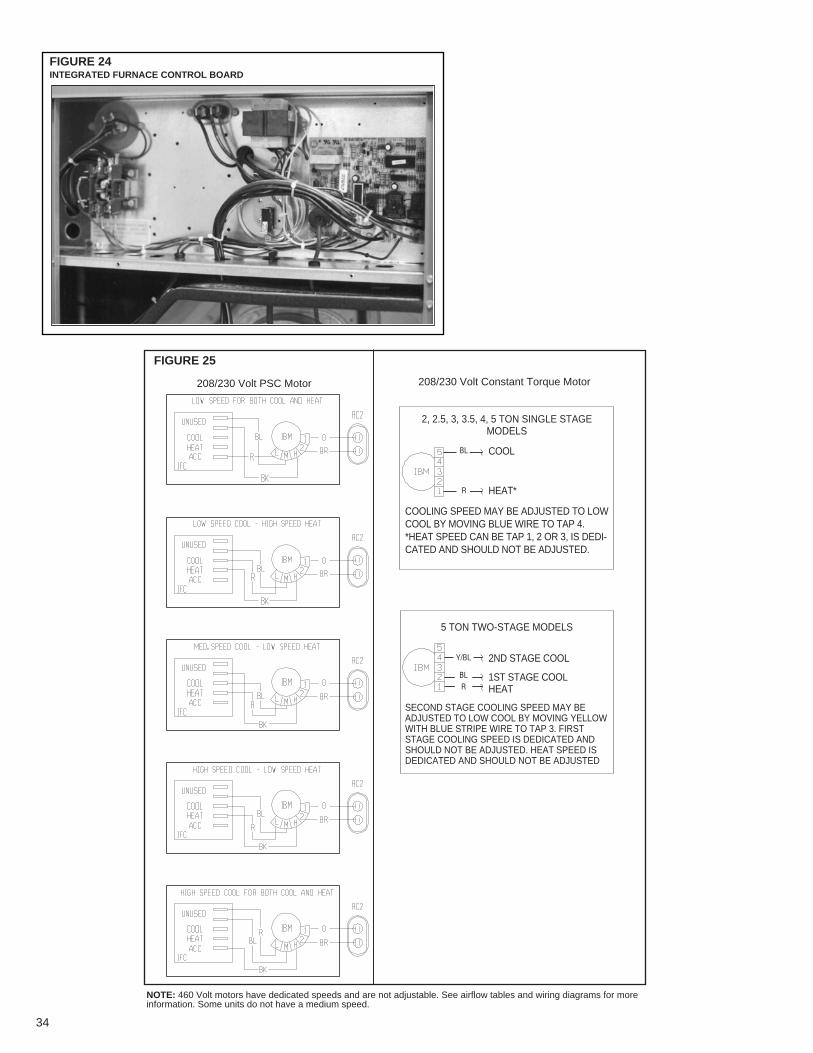
FIGURE 25
208/230 Volt PSC Motor 208/230 Volt Constant Torque Motor
NOTE: 460 Volt motors have dedicated speeds and are not adjustable. See airflow tables and wiring diagrams for moreinformation. Some units do not have a medium speed.
FIGURE 21INTEGRATED FURNACE CONTROL BOARDFIGURE 24INTEGRATED FURNACE CONTROL BOARD
2, 2.5, 3, 3.5, 4, 5 TON SINGLE STAGEMODELS
COOLING SPEED MAY BE ADJUSTED TO LOWCOOL BY MOVING BLUE WIRE TO TAP 4.*HEAT SPEED CAN BE TAP 1, 2 OR 3, IS DEDI-CATED AND SHOULD NOT BE ADJUSTED.
COOL
HEAT*
5 TON TWO-STAGE MODELS
SECOND STAGE COOLING SPEED MAY BEADJUSTED TO LOW COOL BY MOVING YELLOWWITH BLUE STRIPE WIRE TO TAP 3. FIRSTSTAGE COOLING SPEED IS DEDICATED ANDSHOULD NOT BE ADJUSTED. HEAT SPEED ISDEDICATED AND SHOULD NOT BE ADJUSTED
2ND STAGE COOL
1ST STAGE COOLHEAT
Y/BL
BLR
BL
R
34

35
FIGURE 26FACTORY SET BLOWER SPEEDS
RGEA13/14 Blower Speed
Cool Tons Heat Input Cool
Blower Speed
Heat Cool Tons Heat Input Cool Heat
RGEA15
40K High 60K Tap 22
60KHigh
High2
80KTap 5
Tap 3
60K Low 60K Tap 22.5
80KLow
High2.5
80KTap 5
Tap 3
60K Low 60K Tap 1
3 80K High High 3 80K Tap 5 Tap 2
100K High 100K Tap 3
80K Tap 2 80K Tap 23.5
100KTap 5
Tap 33.5
100KTap 5
Tap 3
80K Tap 2 80K Tap 24
100KTap 5
Tap 34
100KTap 5
Tap 3
1st Stage Tap 25 100K Tap 5 Tap 1 5 100K
2nd Stage Tap 5Tap 1
NOTE: See blower tables for speed options.
XI. UNITS WITH ECM BLOWER MOTORSXI. (RGEA15???AJV MODELS ONLY)The ECM (Brushless permanent magnet) motor used on the blower in this product is pro-grammed to operate over a wide range of external static pressures (0.0” - 1.0” W.C.) withessentially constant air flow (CFM). Motor efficiency on ECM type motors is higher than thatof P.S.C. type motors normally used on this type product. See air flow performance datatables.
The ECM motor is programmed to provide a “soft” start and stop. On a call for heat or cool,the motor will gradually ramp up to the field selected CFM speed. This eliminates the suddenrush of air and noise normally associated with a P.S.C. type motor. Once the thermostat andblower delay are satisfied, the motor will gradually ramp down as well.
IMPORTANT: Units equipped with ECM motors cannot be used in by-pass zoning applica-tions.
IMPORTANT: The A.C. power plug to the blower motor has locking tabs. It has been shownthat by applying excessive force to the A.C. cable half of the connector it is possible to forcethe connector in backwards. It will not seat and “click” properly but will make connection. IfA.C. power is applied with the connector reversed the motor will be immediately destroyed. Donot force power plug into motor connector backwards.
NOTE: Because of the harmonic content of the A.C. Line current to the ECM motor a conven-tional ammeter will not read correct motor amps. Only a true RMS meter will give accurateAMP readings.
IMPORTANT: The flexibility of ECM motors and the fact that this flexibility is contained in pro-grammed memory, not hardware, emphasizes the need for exact motor numbers for replace-ment motors. Because they all look the same, ECM MOTORS FROM DIFFERENT PROD-UCTS OR DIFFERENT MODELS OF THE SAME PRODUCT MUST NOT BE INTER-CHANGED.
IMPORTANT: If an ECM motor is replaced, it is important that the motor be mounted as theoriginal, as far into the blower wheel as practical for proper motor cooling.
IMPORTANT: The ECM motor is controlled directly from the room thermostat (in all modesexcept heating). In cooling, the motor is controlled from the thermostat “Y” terminal. When the“Y” or “R” thermostat circuit is opened a 30 second delay will occur before the blower motorwill cycle. In the heating mode the furnace control board controls the ECM through the blowerrelay. When the “W” thermostat circuits are opened, a 90 second delay will occur before theblower will cycle off. When the “G” to “R” thermostat circuit is opened for low speed blower,there is no “off” delay. All thermostat sub-base combinations as recommended and providedthrough the Parts Department have been tested and are compatible with the ECM motor usedin this equipment. Some thermostats may not be compatible with the ECM motor provided inthis unit. With thermostat in off state, the voltage on control lines “G”, “Y”, or W with respect to24 vac common should be less than 3.5 VAC. If the measured voltage is too high, thermostatis incompatible with the ECM motor and will cause the motor to run when it should be off.

36
A. ECM MOTOR INTERFACE CONTROL AND SETTINGSA. (RGEA15???AJV UNITS ONLY)The RGEA15???AJV series units use ECM blower motors to deliver a constant level of air-flow over a wide range of external static pressures (up to 1.0" W.C.). The interface board pro-vides the required communications between the thermostat/IFC and the ECM blower motor.The interface board features:
• An automotive-style ATC blade fuse for transformer protection (3 amp).
• An on-board LED to indicate blower CFM.
• Inputs for two-stages of cooling: Y1 (first stage) and Y2 (second stage)
• Four (4) cooling delay profiles
The DIP switches on the interface board are used to define the operation of the ECM motor(see Table 7).
Refer to Figure 24 for switch identification and factory default settings.
IMPORTANT: Disconnect power to unit when changing DIP switch positions. Even if bloweris not operating, the motor will not recognize changes in DIP switch positions until unit poweris removed and then restored.
B. TRANSFORMER PROTECTIONThe ECM interface board is equipped with an automotive-style 3 amp ATC blade fuse fortransformer protection. (See Figure 27.) If a short circuit occurs on the secondary side of thetransformer, the fuse will open.
TABLE 7SWITCH FUNCTIONS
Switch Function1 & 2 Not Used3 & 4 Cooling Airflow Adjustment5 & 6 Heating Airflow Settings7 & 8 Cooling Delay Profiles9 & 10 On-Demand Dehumidification
FIGURE 28ECM MOTOR SETTINGS
(This board is located in the blower section)
FIGURE 27ECM INTERFACE BOARD LED
FIRST-STAGE COOLING INPUT SECOND-STAGE COOLING INPUT
(THIS BOARD IS LOCATED IN THE BLOWER SECTION)
DO NOT WIRE DIRECTLY TO THIS BOARD. THERMOSTAT SHOULDBE WIRED TO PIGTAILS LOCATED BELOW THE CONTROL BOX.

C. USING THE ON-BOARD LED TO DETERMINE BLOWER CFMThe ECM interface board LED, which is located in the blower section (see Figure 27), indi-cates blower output by flashing one (1) second for every 100 CFM of airflow. The LED willpause 1/10 second between each flash. After the blower CFM has been displayed, the LEDwill illuminate dimly for 10 seconds before repeating the sequence. (See Table 8.)
NOTE: If airflow is not a multiple of 100 CFM, the last LED flash is a fraction of a second of100 CFM.
D. UNIT OPERATION WITH TWO-STAGE COOLINGTwo stage units provide distinct airflows for two-stage cooling. (See Figure 27.) Unit operationis defined as:
• Y1 – First Stage Cooling• Y2 – Second Stage Cooling
A 24VAC signal provides input for the cooling stages.
NOTE: A 24VAC input to the Y2 terminal overrides the input to the Y1 terminal. (Both must beenergized to enable 2nd stage cooling.)
E. COOLING AIRFLOW ADJUSTMENTSCooling airflow may be adjusted +10% or –10% from nominal airflow using switches 3 & 4.
Refer to Figure 30 for switch positions to achieve the desired adjustments in airflow.
NOTE: Continuous fan speed is NOT affected by switches 3 & 4.
IMPORTANT: The use of On Demand Dehumidification overrides the cooling airflow adjust-ments when high humidity is detected by a dehumidifying thermostat or humidistat when con-nected to the ODD terminal as shown in Figure 27. Refer to the Cooling Mode Dehumi di -fication section for more information.
37
TABLE 8LED FLASH CODES
Interface boardDIP switchsettiings
1200 CFM
600 CFM
950 CFM
LED Output
• Flashes 12 times• Illuminate dimly 10 seconds, repeat sequence
• Flashes 6 times• Illuminate dimly 10 seconds, repeat sequence
• Flashes 9 times, flash once for 1/2 second• Illuminate dimly 10 seconds, repeat sequence
TABLE 9TWO-STAGE OPERATION
Y1INPUT
NONE
24 VAC24 VAC
NONE
Y2INPUT
NONE
NONE
24 VAC
24 VAC
COOLINGOPERATION
OFF
1ST STAGE
2ND STAGE
OFF

38
F. HEATING AIRFLOW ADJUSTMENTSHeating airflow may be adjusted +10% or –10% from nominal airflow using switches 5 & 6.
Refer to Figure 30 for switch positions to achieve the desired adjustments in airflow.
NOTE: Continuous fan speed is NOT affected by switches 5 & 6.
G. COOLING DELAY PROFILESThe unit is shipped with a default ON/OFF delay profile for maximum efficiency. This defaultmay be overridden to maximize comfort by using one of the alternate profiles. ON delay pro-files are shown in Figure 31.
OFF delay profiles are shown in Figure 32.
IMPORTANT: Blower ON delay profiles are not used in heating mode.
FIGURE 29COOLING AIRFLOW ADJUSTMENTS
COOLINGSELECTION SWITCH 3 SWITCH 4 AIRFLOW
POSITION POSITION ADJUSTMENT
A OFF OFF NONE
B ON OFF 10%
C OFF ON -10%
D ON ON NONE
ON
ON
ON
ON
A
3 4 3 4 3 4 3 4
B C D
FIGURE 30HEATING AIRFLOW ADJUSTMENTS
HEATINGSELECTION SWITCH 5 SWITCH 6 AIRFLOW
POSITION POSITION ADJUSTMENT
A OFF OFF NONE
B ON OFF 10%
C OFF ON -10%
D ON ON NONE
ON
ON
ON
ON
A
5 6 5 6 5 6 5 6
B C D
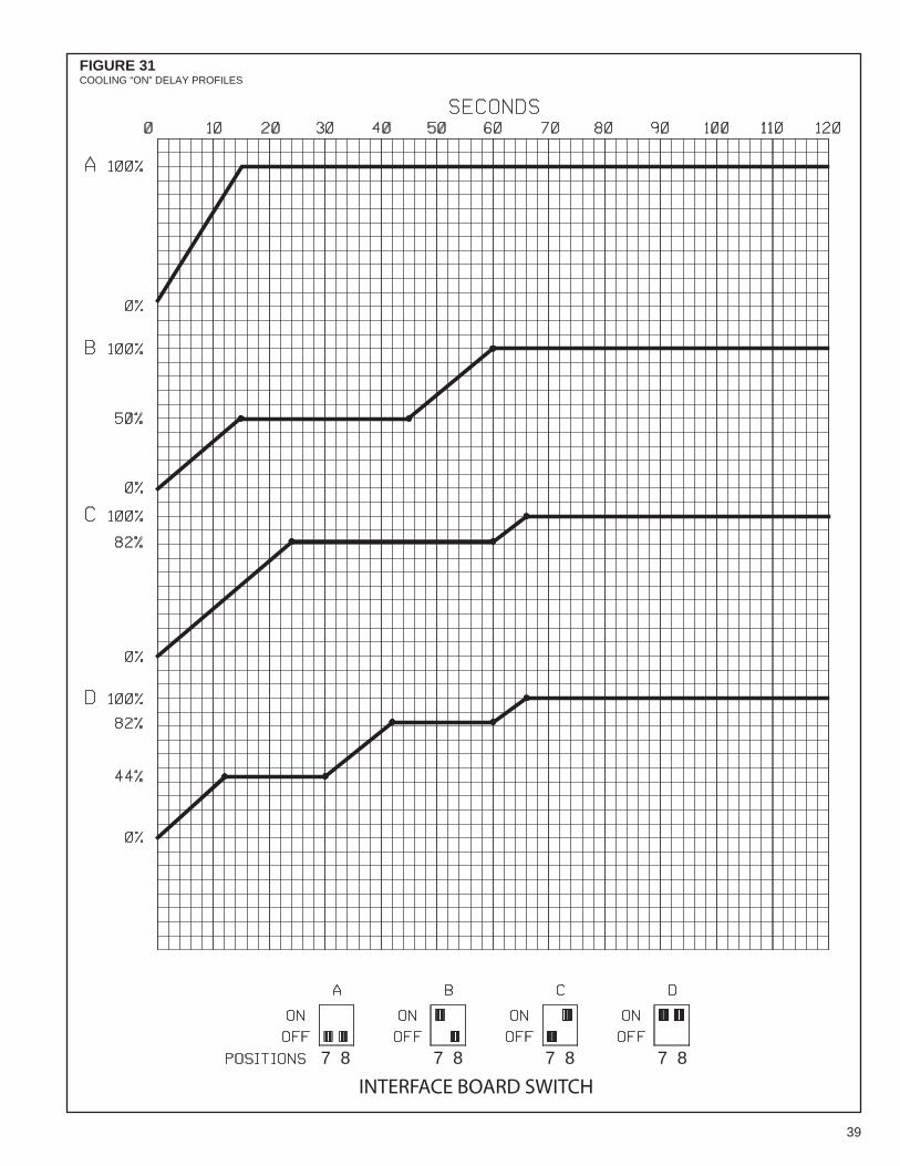
39
FIGURE 31COOLING “ON” DELAY PROFILES
INTERFACE BOARD SWITCH
7 8 7 8 7 8 7 8

40
FIGURE 32BLOWER “OFF” DELAY PROFILES
INTERFACE BOARD SWITCH
7 8 7 8 7 8 7 8

41
XII. GENERAL DATA - RGEA- MODELSNOMINAL SIZES 2-5 TONS [7-15.8 kW]
Model RGEA13 Series 024AJD041AA 024AJD061AA 030AJD061AA 030AJD081AA
Cooling Performance1 Continued -> Gross Cooling Capacity Btu [kW] 24,800 [7.27] 24,800 [7.27] 30,200 [8.85] 30,200 [8.85] EER/SEER2 11.4/13.5 11.4/13.5 12/13.5 12/13.5 Nominal CFM/AHRI Rated CFM [L/s] 800/900 [378/425] 800/900 [378/425] 1000/1000 [472/472] 1000/1000 [472/472] AHRI Net Cooling Capacity Btu [kW] 24,000 [7.03] 24,000 [7.03] 29,000 [8.5] 29,000 [8.5] Net Sensible Capacity Btu [kW] 18,400 [5.39] 18,400 [5.39] 21,300 [6.24] 21,300 [6.24] Net Latent Capacity Btu [kW] 5,600 [1.64] 5,600 [1.64] 7,700 [2.26] 7,700 [2.26] Net System Power kW 2.1 2.1 2.37 2.37
Heating Performance (Gas)4
Heating Input Btu [kW] 40,000 [11.72] 60,000 [17.58] 60,000 [17.58] 80,000 [23.44] Heating Output Btu [kW] 32,000 [9.38] 48,000 [14.06] 48,000 [14.06] 65,000 [19.04] Temperature Rise Range ºF [ºC] 25-55 [13.9-30.6] 40-70 [22.2-38.9] 35-65 [19.4-36.1] 35-65 [19.4-36.1] AFUE % 81 81 81 81 Steady State Efficiency (%) 82 82 82 82 No. Burners 2 2 3 3 No. Stages 1 1 1 1 Gas Connection Pipe Size in. [mm] 0.5 [12.7] 0.5 [12.7] 0.5 [12.7] 0.5 [12.7]Compressor No./Type 1/Scroll 1/Scroll 1/Scroll 1/ScrollOutdoor Sound Rating (dB)5 76 76 76 76Outdoor Coil - Fin Type Louvered Louvered Louvered Louvered Tube Type MicroChannel MicroChannel MicroChannel MicroChannel MicroChannel Depth in. [mm] 0.71 [18] 0.71 [18] 0.71 [18] 0.71 [18] Face Area sq. ft. [sq. m] 7.1 [0.66] 7.1 [0.66] 9.9 [0.92] 9.9 [0.92] Rows / FPI [FPcm] 1 / 23 [9] 1 / 23 [9] 1 / 23 [9] 1 / 23 [9]Indoor Coil - Fin Type Louvered Louvered Louvered Louvered Tube Type MicroChannel MicroChannel MicroChannel MicroChannel MicroChannel Depth in. [mm] 1 [25.4] 1 [25.4] 1 [25.4] 1 [25.4] Face Area sq. ft. [sq. m] 3.6 [0.33] 3.6 [0.33] 3.6 [0.33] 3.6 [0.33] Rows / FPI [FPcm] 1 / 17 [7] 1 / 17 [7] 1 / 23 [9] 1 / 23 [9] Refrigerant Control TX Valves TX Valves TX Valves TX Valves Drain Connection No./Size in. [mm] 1/0.75 [19.05] 1/0.75 [19.05] 1/0.75 [19.05] 1/0.75 [19.05]Outdoor Fan - Type Propeller Propeller Propeller Propeller No. Used/Diameter in. [mm] 1/22 [558.8] 1/22 [558.8] 1/22 [558.8] 1/22 [558.8] Drive Type/No. Speeds Direct/1 Direct/1 Direct/1 Direct/1 CFM [L/s] 2500 [1180] 2500 [1180] 2500 [1180] 2500 [1180] No. Motors/HP 1 at 1/3 HP 1 at 1/3 HP 1 at 1/3 HP 1 at 1/3 HP Motor RPM 1075 1075 1075 1075Indoor Fan - Type FC Centrifugal FC Centrifugal FC Centrifugal FC Centrifugal No. Used/Diameter in. [mm] 1/9x7 [229x178] 1/9x7 [229x178] 1/10x9 [254x229] 1/10x9 [254x229] Drive Type Direct Direct Direct Direct No. Speeds Multiple Multiple Multiple Multiple No. Motors 1 1 1 1 Motor HP 1/4 1/4 1/2 1/2 Motor RPM 1075 1075 1075 1075 Motor Frame Size 48 48 48 48Filter - Type Field Supplied Field Supplied Field Supplied Field Supplied Furnished No No No No (NO.) Size Recommended in. [mm x mm x mm] (1)1x20x20 [25x508x508] (1)1x20x20 [25x508x508] (1)1x24x24 [25x610x610] (1)1x24x24 [25x610x610]
Refrigerant Charge Oz. [g] 42.7 [1211] 42.7 [1211] 46.8 [1327] 46.8 [1327]Weights Net Weight lbs. [kg] 398 [181] 403 [183] 403 [183] 408 [185] Ship Weight lbs. [kg] 408 [185] 413 [187] 413 [187] 418 [190]
NOTES:
1. Cooling Performance is rated at 95°F ambient, 80°F entering dry bulb, 67°F entering wet bulb. Gross capacity does not include the effect of fan motor heat. ARI capacityis net and includes the effect of fan motor heat. Units are suitable for operation to ±20% of nominal cfm. Units are certified in accordance with the Unitary Air ConditionerEquipment certification program, which is based on ARI Standard 210/240 or 360.
2. EER and/or SEER are rated at ARI conditions and in accordance with DOE test procedures.
3. Heating Performance limit settings and rating data were established and approved under laboratory test conditions using American National Standard Institute standards.Ratings shown are for elevations up to 2000 feet. For elevations above 2000 feet, ratings should be reduced at the rate of 4% for each 1000 feet above sea level.
4. ARUE is rated in accordance with DOE test procedures.
5. Outdoor Sound Rating shown is tested in accordance with ARI Standard 270.
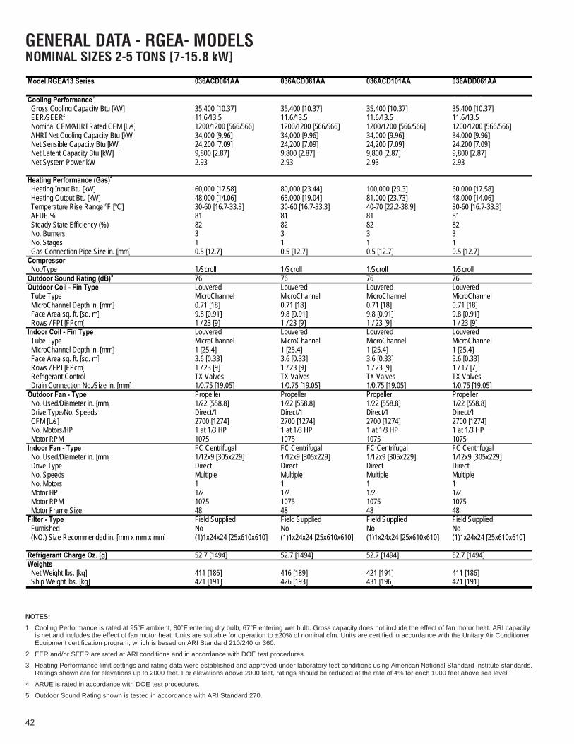
42
GENERAL DATA - RGEA- MODELSNOMINAL SIZES 2-5 TONS [7-15.8 kW]
Model RGEA13 Series 036ACD061AA 036ACD081AA 036ACD101AA 036ADD061AA
Cooling Performance1 Continued -> Gross Cooling Capacity Btu [kW] 35,400 [10.37] 35,400 [10.37] 35,400 [10.37] 35,400 [10.37] EER/SEER2 11.6/13.5 11.6/13.5 11.6/13.5 11.6/13.5 Nominal CFM/AHRI Rated CFM [L/s] 1200/1200 [566/566] 1200/1200 [566/566] 1200/1200 [566/566] 1200/1200 [566/566] AHRI Net Cooling Capacity Btu [kW] 34,000 [9.96] 34,000 [9.96] 34,000 [9.96] 34,000 [9.96] Net Sensible Capacity Btu [kW] 24,200 [7.09] 24,200 [7.09] 24,200 [7.09] 24,200 [7.09] Net Latent Capacity Btu [kW] 9,800 [2.87] 9,800 [2.87] 9,800 [2.87] 9,800 [2.87] Net System Power kW 2.93 2.93 2.93 2.93
Heating Performance (Gas)4
Heating Input Btu [kW] 60,000 [17.58] 80,000 [23.44] 100,000 [29.3] 60,000 [17.58] Heating Output Btu [kW] 48,000 [14.06] 65,000 [19.04] 81,000 [23.73] 48,000 [14.06] Temperature Rise Range ºF [ºC] 30-60 [16.7-33.3] 30-60 [16.7-33.3] 40-70 [22.2-38.9] 30-60 [16.7-33.3] AFUE % 81 81 81 81 Steady State Efficiency (%) 82 82 82 82 No. Burners 3 3 3 3 No. Stages 1 1 1 1 Gas Connection Pipe Size in. [mm] 0.5 [12.7] 0.5 [12.7] 0.5 [12.7] 0.5 [12.7]Compressor No./Type 1/Scroll 1/Scroll 1/Scroll 1/ScrollOutdoor Sound Rating (dB)5 76 76 76 76Outdoor Coil - Fin Type Louvered Louvered Louvered Louvered Tube Type MicroChannel MicroChannel MicroChannel MicroChannel MicroChannel Depth in. [mm] 0.71 [18] 0.71 [18] 0.71 [18] 0.71 [18] Face Area sq. ft. [sq. m] 9.8 [0.91] 9.8 [0.91] 9.8 [0.91] 9.8 [0.91] Rows / FPI [FPcm] 1 / 23 [9] 1 / 23 [9] 1 / 23 [9] 1 / 23 [9]Indoor Coil - Fin Type Louvered Louvered Louvered Louvered Tube Type MicroChannel MicroChannel MicroChannel MicroChannel MicroChannel Depth in. [mm] 1 [25.4] 1 [25.4] 1 [25.4] 1 [25.4] Face Area sq. ft. [sq. m] 3.6 [0.33] 3.6 [0.33] 3.6 [0.33] 3.6 [0.33] Rows / FPI [FPcm] 1 / 23 [9] 1 / 23 [9] 1 / 23 [9] 1 / 17 [7] Refrigerant Control TX Valves TX Valves TX Valves TX Valves Drain Connection No./Size in. [mm] 1/0.75 [19.05] 1/0.75 [19.05] 1/0.75 [19.05] 1/0.75 [19.05]Outdoor Fan - Type Propeller Propeller Propeller Propeller No. Used/Diameter in. [mm] 1/22 [558.8] 1/22 [558.8] 1/22 [558.8] 1/22 [558.8] Drive Type/No. Speeds Direct/1 Direct/1 Direct/1 Direct/1 CFM [L/s] 2700 [1274] 2700 [1274] 2700 [1274] 2700 [1274] No. Motors/HP 1 at 1/3 HP 1 at 1/3 HP 1 at 1/3 HP 1 at 1/3 HP Motor RPM 1075 1075 1075 1075Indoor Fan - Type FC Centrifugal FC Centrifugal FC Centrifugal FC Centrifugal No. Used/Diameter in. [mm] 1/12x9 [305x229] 1/12x9 [305x229] 1/12x9 [305x229] 1/12x9 [305x229] Drive Type Direct Direct Direct Direct No. Speeds Multiple Multiple Multiple Multiple No. Motors 1 1 1 1 Motor HP 1/2 1/2 1/2 1/2 Motor RPM 1075 1075 1075 1075 Motor Frame Size 48 48 48 48Filter - Type Field Supplied Field Supplied Field Supplied Field Supplied Furnished No No No No (NO.) Size Recommended in. [mm x mm x mm] (1)1x24x24 [25x610x610] (1)1x24x24 [25x610x610] (1)1x24x24 [25x610x610] (1)1x24x24 [25x610x610]
Refrigerant Charge Oz. [g] 52.7 [1494] 52.7 [1494] 52.7 [1494] 52.7 [1494]Weights Net Weight lbs. [kg] 411 [186] 416 [189] 421 [191] 411 [186] Ship Weight lbs. [kg] 421 [191] 426 [193] 431 [196] 421 [191]
NOTES:
1. Cooling Performance is rated at 95°F ambient, 80°F entering dry bulb, 67°F entering wet bulb. Gross capacity does not include the effect of fan motor heat. ARI capacityis net and includes the effect of fan motor heat. Units are suitable for operation to ±20% of nominal cfm. Units are certified in accordance with the Unitary Air ConditionerEquipment certification program, which is based on ARI Standard 210/240 or 360.
2. EER and/or SEER are rated at ARI conditions and in accordance with DOE test procedures.
3. Heating Performance limit settings and rating data were established and approved under laboratory test conditions using American National Standard Institute standards.Ratings shown are for elevations up to 2000 feet. For elevations above 2000 feet, ratings should be reduced at the rate of 4% for each 1000 feet above sea level.
4. ARUE is rated in accordance with DOE test procedures.
5. Outdoor Sound Rating shown is tested in accordance with ARI Standard 270.

43
GENERAL DATA - RGEA- MODELSNOMINAL SIZES 2-5 TONS [7-15.8 kW]
(NO.) Size Recommended in. [mm x mm x mm] (1)1x24x24 [25x610x610] (1)1x24x24 [25x610x610] (1)1x24x24 [25x610x610] (1)1x24x24 [25x610x610]
Ship Weight lbs. [kg] 426 [193] 431 [196] 421 [191] 426 [193]
Model RGEA13 Series 036ADD081AA 036ADD101AA 036AJD061AA 036AJD081AA
Cooling Performance1 Continued -> Gross Cooling Capacity Btu [kW] 35,400 [10.37] 35,400 [10.37] 35,400 [10.37] 35,400 [10.37] EER/SEER2 11.6/13.5 11.6/13.5 11.6/13.5 11.6/13.5 Nominal CFM/AHRI Rated CFM [L/s] 1200/1200 [566/566] 1200/1200 [566/566] 1200/1200 [566/566] 1200/1200 [566/566] AHRI Net Cooling Capacity Btu [kW] 34,000 [9.96] 34,000 [9.96] 34,000 [9.96] 34,000 [9.96] Net Sensible Capacity Btu [kW] 24,200 [7.09] 24,200 [7.09] 24,200 [7.09] 24,200 [7.09] Net Latent Capacity Btu [kW] 9,800 [2.87] 9,800 [2.87] 9,800 [2.87] 9,800 [2.87] Net System Power kW 2.93 2.93 2.93 2.93
Heating Performance (Gas)4
Heating Input Btu [kW] 80,000 [23.44] 100,000 [29.3] 60,000 [17.58] 80,000 [23.44] Heating Output Btu [kW] 65,000 [19.04] 81,000 [23.73] 48,000 [14.06] 65,000 [19.04] Temperature Rise Range ºF [ºC] 30-60 [16.7-33.3] 40-70 [22.2-38.9] 30-60 [16.7-33.3] 30-60 [16.7-33.3] AFUE % 81 81 81 81 Steady State Efficiency (%) 82 82 82 82 No. Burners 3 3 3 3 No. Stages 1 1 1 1 Gas Connection Pipe Size in. [mm] 0.5 [12.7] 0.5 [12.7] 0.5 [12.7] 0.5 [12.7]Compressor No./TypeOutdoor Sound Rating (dB)5
1/Scroll 1/Scroll 1/Scroll 1/Scroll
Outdoor Coil - Fin Type76 76 76 76Louvered Louvered Louvered Louvered
Tube Type MicroChannel MicroChannel MicroChannel MicroChannel MicroChannel Depth in. [mm] 0.71 [18] 0.71 [18] 0.71 [18] 0.71 [18] Face Area sq. ft. [sq. m] 9.8 [0.91] 9.8 [0.91] 9.8 [0.91] 9.8 [0.91] Rows / FPI [FPcm] 1 / 23 [9] 1 / 23 [9] 1 / 23 [9] 1 / 23 [9]Indoor Coil - Fin Type Louvered Louvered Louvered Louvered Tube Type MicroChannel MicroChannel MicroChannel MicroChannel MicroChannel Depth in. [mm] 1 [25.4] 1 [25.4] 1 [25.4] 1 [25.4] Face Area sq. ft. [sq. m] 3.6 [0.33] 3.6 [0.33] 3.6 [0.33] 3.6 [0.33] Rows / FPI [FPcm] 1 / 17 [7] 1 / 17 [7] 1 / 17 [7] 1 / 17 [7] Refrigerant Control TX Valves TX Valves TX Valves TX Valves Drain Connection No./Size in. [mm] 1/0.75 [19.05] 1/0.75 [19.05] 1/0.75 [19.05] 1/0.75 [19.05]Outdoor Fan - Type Propeller Propeller Propeller Propeller No. Used/Diameter in. [mm] 1/22 [558.8] 1/22 [558.8] 1/22 [558.8] 1/22 [558.8] Drive Type/No. Speeds Direct/1 Direct/1 Direct/1 Direct/1 CFM [L/s] 2700 [1274] 2700 [1274] 2700 [1274] 2700 [1274] No. Motors/HP 1 at 1/3 HP 1 at 1/3 HP 1 at 1/3 HP 1 at 1/3 HP Motor RPM 1075 1075 1075 1075Indoor Fan - Type FC Centrifugal FC Centrifugal FC Centrifugal FC Centrifugal No. Used/Diameter in. [mm] 1/12x9 [305x229] 1/12x9 [305x229] 1/12x9 [305x229] 1/12x9 [305x229] Drive Type Direct Direct Direct Direct No. Speeds Multiple Multiple Multiple Multiple No. Motors 1 1 1 1 Motor HP 1/2 1/2 1/2 1/2 Motor RPM 1075 1075 1075 1075 Motor Frame Size 48 48 48 48Filter - Type Field Supplied Field Supplied Field Supplied Field Supplied Furnished No No No No
Refrigerant Charge Oz. [g] 52.7 [1494] 52.7 [1494] 52.7 [1494] 52.7 [1494]Weights Net Weight lbs. [kg] 416 [189] 421 [191] 411 [186] 416 [189]
NOTES:
1. Cooling Performance is rated at 95°F ambient, 80°F entering dry bulb, 67°F entering wet bulb. Gross capacity does not include the effect of fan motor heat. ARI capacityis net and includes the effect of fan motor heat. Units are suitable for operation to ±20% of nominal cfm. Units are certified in accordance with the Unitary Air ConditionerEquipment certification program, which is based on ARI Standard 210/240 or 360.
2. EER and/or SEER are rated at ARI conditions and in accordance with DOE test procedures.
3. Heating Performance limit settings and rating data were established and approved under laboratory test conditions using American National Standard Institute standards.Ratings shown are for elevations up to 2000 feet. For elevations above 2000 feet, ratings should be reduced at the rate of 4% for each 1000 feet above sea level.
4. ARUE is rated in accordance with DOE test procedures.
5. Outdoor Sound Rating shown is tested in accordance with ARI Standard 270.

44
GENERAL DATA - RGEA- MODELSNOMINAL SIZES 2-5 TONS [7-15.8 kW]
Model RGEA13 Series 036AJD101AA 042ACT081AA 042ACT101AA 042AJT081AA
Net System Power kW 2.93 3.27 3.27 3.27
(NO.) Size Recommended in. [mm x mm x mm] (1)1x24x24 [25x610x610] (1)1x24x24 [25x610x610] (1)1x24x24 [25x610x610] (1)1x24x24 [25x610x610]
Ship Weight lbs. [kg] 431 [196] 451 [205] 456 [207] 451 [205]
1Cooling Performance Continued -> Gross Cooling Capacity Btu [kW]
235,400 [10.37] 41,000 [12.01] 41,000 [12.01] 41,000 [12.01]
EER/SEER 11.6/13.5 12/13.5 12/13.5 12/13.5 Nominal CFM/AHRI Rated CFM [L/s] 1200/1200 [566/566] 1400/1300 [661/613] 1400/1300 [661/613] 1400/1300 [661/613] AHRI Net Cooling Capacity Btu [kW] 34,000 [9.96] 40,000 [11.72] 40,000 [11.72] 40,000 [11.72] Net Sensible Capacity Btu [kW] 24,200 [7.09] 29,000 [8.5] 29,000 [8.5] 29,000 [8.5] Net Latent Capacity Btu [kW] 9,800 [2.87] 11,000 [3.22] 11,000 [3.22] 11,000 [3.22]
4Heating Performance (Gas) Heating Input Btu [kW] 100,000 [29.3] 80,000 [23.44] 100,000 [29.3] 80,000 [23.44] Heating Output Btu [kW] 81,000 [23.73] 65,000 [19.04] 81,000 [23.73] 65,000 [19.04] Temperature Rise Range ºF [ºC] 40-70 [22.2-38.9] 35-65 [19.4-36.1] 45-75 [25-41.7] 35-65 [19.4-36.1] AFUE % 81 81 81 81 Steady State Efficiency (%) 82 82 82 82 No. Burners 3 4 4 4 No. Stages 1 1 1 1 Gas Connection Pipe Size in. [mm] 0.5 [12.7] 0.5 [12.7] 0.5 [12.7] 0.5 [12.7]Compressor No./Type
51/Scroll 1/Scroll 1/Scroll 1/Scroll
Outdoor Sound Rating (dB) 76 76 76 76Outdoor Coil - Fin Type Louvered Louvered Louvered Louvered Tube Type MicroChannel MicroChannel MicroChannel MicroChannel MicroChannel Depth in. [mm] 0.71 [18] 0.71 [18] 0.71 [18] 0.71 [18] Face Area sq. ft. [sq. m] 9.8 [0.91] 14.1 [1.31] 14.1 [1.31] 14.1 [1.31] Rows / FPI [FPcm] 1 / 23 [9] 1 / 23 [9] 1 / 23 [9] 1 / 23 [9]Indoor Coil - Fin Type Louvered Louvered Louvered Louvered Tube Type MicroChannel MicroChannel MicroChannel MicroChannel MicroChannel Depth in. [mm] 1 [25.4] 1 [25.4] 1 [25.4] 1 [25.4] Face Area sq. ft. [sq. m] 3.6 [0.33] 3.6 [0.33] 3.6 [0.33] 3.6 [0.33] Rows / FPI [FPcm] 1 / 17 [7] 1 / 17 [7] 1 / 17 [7] 1 / 17 [7] Refrigerant Control TX Valves TX Valves TX Valves TX Valves Drain Connection No./Size in. [mm] 1/0.75 [19.05] 1/0.75 [19.05] 1/0.75 [19.05] 1/0.75 [19.05]Outdoor Fan - Type Propeller Propeller Propeller Propeller No. Used/Diameter in. [mm] 1/22 [558.8] 1/22 [558.8] 1/22 [558.8] 1/22 [558.8] Drive Type/No. Speeds Direct/1 Direct/1 Direct/1 Direct/1 CFM [L/s] 2700 [1274] 3500 [1652] 3500 [1652] 3500 [1652] No. Motors/HP 1 at 1/3 HP 1 at 1/3 HP 1 at 1/3 HP 1 at 1/3 HP Motor RPM 1075 1075 1075 1075Indoor Fan - Type FC Centrifugal FC Centrifugal FC Centrifugal FC Centrifugal No. Used/Diameter in. [mm] 1/12x9 [305x229] 1/12x9 [305x229] 1/12x9 [305x229] 1/12x9 [305x229] Drive Type Direct Direct Direct Direct No. Speeds Multiple Multiple Multiple Multiple No. Motors 1 1 1 1 Motor HP 1/2 3/4 3/4 3/4 Motor RPM 1075 1075 1075 1075 Motor Frame Size 48 48 48 48Filter - Type Field Supplied Field Supplied Field Supplied Field Supplied Furnished No No No No
Refrigerant Charge Oz. [g] 52.7 [1494] 53.6 [1520] 53.6 [1520] 53.6 [1520]Weights Net Weight lbs. [kg] 421 [191] 441 [200] 446 [202] 441 [200]
NOTES:
1. Cooling Performance is rated at 95°F ambient, 80°F entering dry bulb, 67°F entering wet bulb. Gross capacity does not include the effect of fan motor heat. ARI capacityis net and includes the effect of fan motor heat. Units are suitable for operation to ±20% of nominal cfm. Units are certified in accordance with the Unitary Air ConditionerEquipment certification program, which is based on ARI Standard 210/240 or 360.
2. EER and/or SEER are rated at ARI conditions and in accordance with DOE test procedures.
3. Heating Performance limit settings and rating data were established and approved under laboratory test conditions using American National Standard Institute standards.Ratings shown are for elevations up to 2000 feet. For elevations above 2000 feet, ratings should be reduced at the rate of 4% for each 1000 feet above sea level.
4. ARUE is rated in accordance with DOE test procedures.
5. Outdoor Sound Rating shown is tested in accordance with ARI Standard 270.
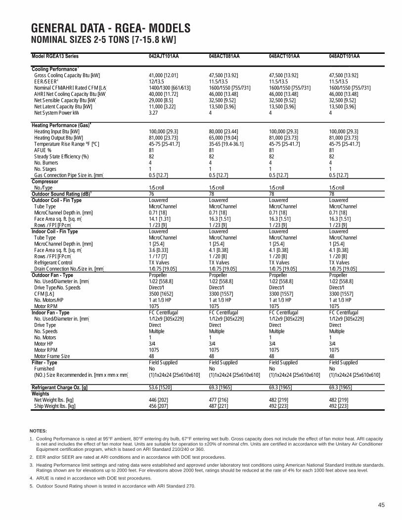
45
Model RGEA13 Series 042AJT101AA 048ACT081AA 048ACT101AA 048ADT101AA
Net System Power kW 3.27 4 4 4
(NO.) Size Recommended in. [mm x mm x mm] (1)1x24x24 [25x610x610] (1)1x24x24 [25x610x610] (1)1x24x24 [25x610x610] (1)1x24x24 [25x610x610]
Ship Weight lbs. [kg] 456 [207] 487 [221] 492 [223] 492 [223]
Cooling Performance1 Continued -> Gross Cooling Capacity Btu [kW] 41,000 [12.01] 47,500 [13.92] 47,500 [13.92] 47,500 [13.92] EER/SEER2 12/13.5 11.5/13.5 11.5/13.5 11.5/13.5 Nominal CFM/AHRI Rated CFM [L/s] 1400/1300 [661/613] 1600/1550 [755/731] 1600/1550 [755/731] 1600/1550 [755/731] AHRI Net Cooling Capacity Btu [kW] 40,000 [11.72] 46,000 [13.48] 46,000 [13.48] 46,000 [13.48] Net Sensible Capacity Btu [kW] 29,000 [8.5] 32,500 [9.52] 32,500 [9.52] 32,500 [9.52] Net Latent Capacity Btu [kW] 11,000 [3.22] 13,500 [3.96] 13,500 [3.96] 13,500 [3.96]
Heating Performance (Gas)4
Heating Input Btu [kW] 100,000 [29.3] 80,000 [23.44] 100,000 [29.3] 100,000 [29.3] Heating Output Btu [kW] 81,000 [23.73] 65,000 [19.04] 81,000 [23.73] 81,000 [23.73] Temperature Rise Range ºF [ºC] 45-75 [25-41.7] 35-65 [19.4-36.1] 45-75 [25-41.7] 45-75 [25-41.7] AFUE % 81 81 81 81 Steady State Efficiency (%) 82 82 82 82 No. Burners 4 4 4 4 No. Stages 1 1 1 1 Gas Connection Pipe Size in. [mm] 0.5 [12.7] 0.5 [12.7] 0.5 [12.7] 0.5 [12.7]Compressor No./Type 1/Scroll 1/Scroll 1/Scroll 1/ScrollOutdoor Sound Rating (dB)5 76 78 78 78Outdoor Coil - Fin Type Louvered Louvered Louvered Louvered Tube Type MicroChannel MicroChannel MicroChannel MicroChannel MicroChannel Depth in. [mm] 0.71 [18] 0.71 [18] 0.71 [18] 0.71 [18] Face Area sq. ft. [sq. m] 14.1 [1.31] 16.3 [1.51] 16.3 [1.51] 16.3 [1.51] Rows / FPI [FPcm] 1 / 23 [9] 1 / 23 [9] 1 / 23 [9] 1 / 23 [9]Indoor Coil - Fin Type Louvered Louvered Louvered Louvered Tube Type MicroChannel MicroChannel MicroChannel MicroChannel MicroChannel Depth in. [mm] 1 [25.4] 1 [25.4] 1 [25.4] 1 [25.4] Face Area sq. ft. [sq. m] 3.6 [0.33] 4.1 [0.38] 4.1 [0.38] 4.1 [0.38] Rows / FPI [FPcm] 1 / 17 [7] 1 / 20 [8] 1 / 20 [8] 1 / 20 [8] Refrigerant Control TX Valves TX Valves TX Valves TX Valves Drain Connection No./Size in. [mm] 1/0.75 [19.05] 1/0.75 [19.05] 1/0.75 [19.05] 1/0.75 [19.05]Outdoor Fan - Type Propeller Propeller Propeller Propeller No. Used/Diameter in. [mm] 1/22 [558.8] 1/22 [558.8] 1/22 [558.8] 1/22 [558.8] Drive Type/No. Speeds Direct/1 Direct/1 Direct/1 Direct/1 CFM [L/s] 3500 [1652] 3300 [1557] 3300 [1557] 3300 [1557] No. Motors/HP 1 at 1/3 HP 1 at 1/3 HP 1 at 1/3 HP 1 at 1/3 HP Motor RPM 1075 1075 1075 1075Indoor Fan - Type FC Centrifugal FC Centrifugal FC Centrifugal FC Centrifugal No. Used/Diameter in. [mm] 1/12x9 [305x229] 1/12x9 [305x229] 1/12x9 [305x229] 1/12x9 [305x229] Drive Type Direct Direct Direct Direct No. Speeds Multiple Multiple Multiple Multiple No. Motors 1 1 1 1 Motor HP 3/4 3/4 3/4 3/4 Motor RPM 1075 1075 1075 1075 Motor Frame Size 48 48 48 48Filter - Type Field Supplied Field Supplied Field Supplied Field Supplied Furnished No No No No
Refrigerant Charge Oz. [g] 53.6 [1520] 69.3 [1965] 69.3 [1965] 69.3 [1965]Weights Net Weight lbs. [kg] 446 [202] 477 [216] 482 [219] 482 [219]
GENERAL DATA - RGEA- MODELSNOMINAL SIZES 2-5 TONS [7-15.8 kW]
NOTES:
1. Cooling Performance is rated at 95°F ambient, 80°F entering dry bulb, 67°F entering wet bulb. Gross capacity does not include the effect of fan motor heat. ARI capacityis net and includes the effect of fan motor heat. Units are suitable for operation to ±20% of nominal cfm. Units are certified in accordance with the Unitary Air ConditionerEquipment certification program, which is based on ARI Standard 210/240 or 360.
2. EER and/or SEER are rated at ARI conditions and in accordance with DOE test procedures.
3. Heating Performance limit settings and rating data were established and approved under laboratory test conditions using American National Standard Institute standards.Ratings shown are for elevations up to 2000 feet. For elevations above 2000 feet, ratings should be reduced at the rate of 4% for each 1000 feet above sea level.
4. ARUE is rated in accordance with DOE test procedures.
5. Outdoor Sound Rating shown is tested in accordance with ARI Standard 270.

46
GENERAL DATA - RGEA- MODELSNOMINAL SIZES 2-5 TONS [7-15.8 kW]
Model RGEA13 Series 048AJT081AA 048AJT101AA 060ACT101AA 060ADT101AA
Net System Power kW 4 4 5.17 5.17
(NO.) Size Recommended in. [mm x mm x mm] (1)1x24x24 [25x610x610] (1)1x24x24 [25x610x610] (1)1x24x30 [25x610x762] (1)1x24x30 [25x610x762]
Ship Weight lbs. [kg] 487 [221] 492 [223] 522 [237] 522 [237]
Cooling Performance1 Continued -> Gross Cooling Capacity Btu [kW] 47,500 [13.92] 47,500 [13.92] 60,000 [17.58] 60,000 [17.58] EER/SEER2 11.5/13.5 11.5/13.5 11/13 11/13 Nominal CFM/AHRI Rated CFM [L/s] 1600/1550 [755/731] 1600/1550 [755/731] 2000/1850 [944/873] 2000/1850 [944/873] AHRI Net Cooling Capacity Btu [kW] 46,000 [13.48] 46,000 [13.48] 57,500 [16.85] 57,500 [16.85] Net Sensible Capacity Btu [kW] 32,500 [9.52] 32,500 [9.52] 40,300 [11.81] 40,300 [11.81] Net Latent Capacity Btu [kW] 13,500 [3.96] 13,500 [3.96] 17,200 [5.04] 17,200 [5.04]
Heating Performance (Gas)4
Heating Input Btu [kW] 80,000 [23.44] 100,000 [29.3] 100,000 [29.3] 100,000 [29.3] Heating Output Btu [kW] 65,000 [19.04] 81,000 [23.73] 81,000 [23.73] 81,000 [23.73] Temperature Rise Range ºF [ºC] 35-65 [19.4-36.1] 45-75 [25-41.7] 45-75 [25-41.7] 45-75 [25-41.7] AFUE % 81 81 81 81 Steady State Efficiency (%) 82 82 82 82 No. Burners 4 4 5 5 No. Stages 1 1 1 1 Gas Connection Pipe Size in. [mm] 0.5 [12.7] 0.5 [12.7] 0.5 [12.7] 0.5 [12.7]Compressor No./Type 1/Scroll 1/Scroll 1/Scroll 1/ScrollOutdoor Sound Rating (dB)5 78 78 79 79Outdoor Coil - Fin Type Louvered Louvered Louvered Louvered Tube Type MicroChannel MicroChannel MicroChannel MicroChannel MicroChannel Depth in. [mm] 0.71 [18] 0.71 [18] 0.71 [18] 0.71 [18] Face Area sq. ft. [sq. m] 16.3 [1.51] 16.3 [1.51] 16.3 [1.51] 16.3 [1.51] Rows / FPI [FPcm] 1 / 23 [9] 1 / 23 [9] 1 / 23 [9] 1 / 23 [9]Indoor Coil - Fin Type Louvered Louvered Louvered Louvered Tube Type MicroChannel MicroChannel MicroChannel MicroChannel MicroChannel Depth in. [mm] 1 [25.4] 1 [25.4] 1.26 [32] 1.26 [32] Face Area sq. ft. [sq. m] 4.1 [0.38] 4.1 [0.38] 4 [0.37] 4 [0.37] Rows / FPI [FPcm] 1 / 20 [8] 1 / 20 [8] 1 / 20 [8] 1 / 20 [8] Refrigerant Control TX Valves TX Valves TX Valves TX Valves Drain Connection No./Size in. [mm] 1/0.75 [19.05] 1/0.75 [19.05] 1/0.75 [19.05] 1/0.75 [19.05]Outdoor Fan - Type Propeller Propeller Propeller Propeller No. Used/Diameter in. [mm] 1/22 [558.8] 1/22 [558.8] 1/22 [558.8] 1/22 [558.8] Drive Type/No. Speeds Direct/1 Direct/1 Direct/1 Direct/1 CFM [L/s] 3300 [1557] 3300 [1557] 3400 [1604] 3400 [1604] No. Motors/HP 1 at 1/3 HP 1 at 1/3 HP 1 at 1/3 HP 1 at 1/3 HP Motor RPM 1075 1075 1075 1075Indoor Fan - Type FC Centrifugal FC Centrifugal FC Centrifugal FC Centrifugal No. Used/Diameter in. [mm] 1/12x9 [305x229] 1/12x9 [305x229] 1/12x9 [305x229] 1/12x9 [305x229] Drive Type Direct Direct Direct Direct No. Speeds Multiple Multiple Multiple Multiple No. Motors 1 1 1 1 Motor HP 3/4 3/4 1 1 Motor RPM 1075 1075 1075 1075 Motor Frame Size 48 48 48 48Filter - Type Field Supplied Field Supplied Field Supplied Field Supplied Furnished No No No No
Refrigerant Charge Oz. [g] 69.3 [1965] 69.3 [1965] 66.1 [1874] 66.1 [1874]Weights Net Weight lbs. [kg] 477 [216] 482 [219] 512 [232] 512 [232]
NOTES:
1. Cooling Performance is rated at 95°F ambient, 80°F entering dry bulb, 67°F entering wet bulb. Gross capacity does not include the effect of fan motor heat. ARI capacityis net and includes the effect of fan motor heat. Units are suitable for operation to ±20% of nominal cfm. Units are certified in accordance with the Unitary Air ConditionerEquipment certification program, which is based on ARI Standard 210/240 or 360.
2. EER and/or SEER are rated at ARI conditions and in accordance with DOE test procedures.
3. Heating Performance limit settings and rating data were established and approved under laboratory test conditions using American National Standard Institute standards.Ratings shown are for elevations up to 2000 feet. For elevations above 2000 feet, ratings should be reduced at the rate of 4% for each 1000 feet above sea level.
4. ARUE is rated in accordance with DOE test procedures.
5. Outdoor Sound Rating shown is tested in accordance with ARI Standard 270.
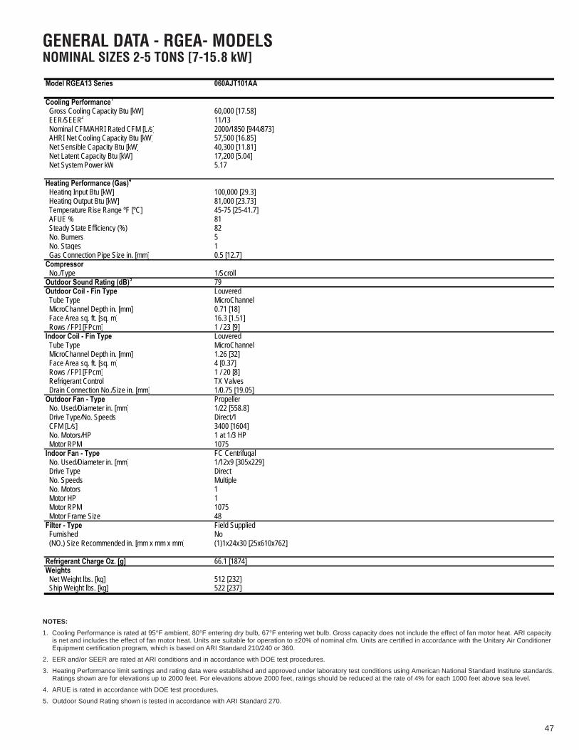
47
GENERAL DATA - RGEA- MODELSNOMINAL SIZES 2-5 TONS [7-15.8 kW]
Model RGEA13 Series 060AJT101AA
Net Latent Capacity Btu [kW] 17,200 [5.04]
Weights Net Weight lbs. [kg] 512 [232] Ship Weight lbs. [kg] 522 [237]
Cooling Performance1
Gross Cooling Capacity Btu [kW] 60,000 [17.58] EER/SEER2 11/13 Nominal CFM/AHRI Rated CFM [L/s] 2000/1850 [944/873] AHRI Net Cooling Capacity Btu [kW] 57,500 [16.85] Net Sensible Capacity Btu [kW] 40,300 [11.81]
Net System Power kW 5.17
4Heating Performance (Gas) Heating Input Btu [kW] 100,000 [29.3] Heating Output Btu [kW] 81,000 [23.73] Temperature Rise Range ºF [ºC] 45-75 [25-41.7] AFUE % 81 Steady State Efficiency (%) 82 No. Burners 5 No. Stages 1 Gas Connection Pipe Size in. [mm] 0.5 [12.7]Compressor No./Type 1/ScrollOutdoor Sound Rating (dB)5 79Outdoor Coil - Fin Type Louvered Tube Type MicroChannel MicroChannel Depth in. [mm] 0.71 [18] Face Area sq. ft. [sq. m] 16.3 [1.51] Rows / FPI [FPcm] 1 / 23 [9]Indoor Coil - Fin Type Louvered Tube Type MicroChannel MicroChannel Depth in. [mm] 1.26 [32] Face Area sq. ft. [sq. m] 4 [0.37] Rows / FPI [FPcm] 1 / 20 [8] Refrigerant Control TX Valves Drain Connection No./Size in. [mm] 1/0.75 [19.05]Outdoor Fan - Type Propeller No. Used/Diameter in. [mm] 1/22 [558.8] Drive Type/No. Speeds Direct/1 CFM [L/s] 3400 [1604] No. Motors/HP 1 at 1/3 HP Motor RPM 1075Indoor Fan - Type FC Centrifugal No. Used/Diameter in. [mm] 1/12x9 [305x229] Drive Type Direct No. Speeds Multiple No. Motors 1 Motor HP 1 Motor RPM 1075 Motor Frame Size 48Filter - Type Field Supplied Furnished No (NO.) Size Recommended in. [mm x mm x mm] (1)1x24x30 [25x610x762]
Refrigerant Charge Oz. [g] 66.1 [1874]
NOTES:
1. Cooling Performance is rated at 95°F ambient, 80°F entering dry bulb, 67°F entering wet bulb. Gross capacity does not include the effect of fan motor heat. ARI capacityis net and includes the effect of fan motor heat. Units are suitable for operation to ±20% of nominal cfm. Units are certified in accordance with the Unitary Air ConditionerEquipment certification program, which is based on ARI Standard 210/240 or 360.
2. EER and/or SEER are rated at ARI conditions and in accordance with DOE test procedures.
3. Heating Performance limit settings and rating data were established and approved under laboratory test conditions using American National Standard Institute standards.Ratings shown are for elevations up to 2000 feet. For elevations above 2000 feet, ratings should be reduced at the rate of 4% for each 1000 feet above sea level.
4. ARUE is rated in accordance with DOE test procedures.
5. Outdoor Sound Rating shown is tested in accordance with ARI Standard 270.

48
GENERAL DATA - RGEA- MODELSNOMINAL SIZES 2-5 TONS [7-15.8 kW]
Model RGEA14 Series 024AJD041AA 024AJD04XAA 024AJD061AA 024AJD06XAA
Cooling Performance1 Continued -> Gross Cooling Capacity Btu [kW] 24,800 [7.27] 24,800 [7.27] 24,800 [7.27] 24,800 [7.27] EER/SEER2 11.6/14 11.6/14 11.6/14 11.6/14 Nominal CFM/AHRI Rated CFM [L/s] 800/900 [378/425] 800/900 [378/425] 800/900 [378/425] 800/900 [378/425] AHRI Net Cooling Capacity Btu [kW] 24,000 [7.03] 24,000 [7.03] 24,000 [7.03] 24,000 [7.03] Net Sensible Capacity Btu [kW] 18,000 [5.27] 18,000 [5.27] 18,000 [5.27] 18,000 [5.27] Net Latent Capacity Btu [kW] 6,000 [1.76] 6,000 [1.76] 6,000 [1.76] 6,000 [1.76] Net System Power kW 2.07 2.07 2.07 2.07
Heating Performance (Gas)4
Heating Input Btu [kW] 40,000 [11.72] 40,000 [11.72] 60,000 [17.58] 60,000 [17.58] Heating Output Btu [kW] 32,000 [9.38] 32,000 [9.38] 48,000 [14.06] 48,000 [14.06] Temperature Rise Range ºF [ºC] 25-55 [13.9-30.6] 25-55 [13.9-30.6] 40-70 [22.2-38.9] 40-70 [22.2-38.9] AFUE % 81 81 81 81 Steady State Efficiency (%) 82 82 82 82 No. Burners 2 2 2 2 No. Stages 1 1 1 1 Gas Connection Pipe Size in. [mm] 0.5 [12.7] 0.5 [12.7] 0.5 [12.7] 0.5 [12.7]Compressor No./Type 1/Scroll 1/Scroll 1/Scroll 1/ScrollOutdoor Sound Rating (dB)5 76 76 76 76Outdoor Coil - Fin Type Louvered Louvered Louvered Louvered Tube Type MicroChannel MicroChannel MicroChannel MicroChannel MicroChannel Depth in. [mm] 0.71 [18] 0.71 [18] 0.71 [18] 0.71 [18] Face Area sq. ft. [sq. m] 7.1 [0.66] 7.1 [0.66] 7.1 [0.66] 7.1 [0.66] Rows / FPI [FPcm] 1 / 23 [9] 1 / 23 [9] 1 / 23 [9] 1 / 23 [9]Indoor Coil - Fin Type Louvered Louvered Louvered Louvered Tube Type MicroChannel MicroChannel MicroChannel MicroChannel MicroChannel Depth in. [mm] 1 [25.4] 1 [25.4] 1 [25.4] 1 [25.4] Face Area sq. ft. [sq. m] 3.6 [0.33] 3.6 [0.33] 3.6 [0.33] 3.6 [0.33] Rows / FPI [FPcm] 1 / 17 [7] 1 / 17 [7] 1 / 17 [7] 1 / 17 [7] Refrigerant Control TX Valves TX Valves TX Valves TX Valves Drain Connection No./Size in. [mm] 1/0.75 [19.05] 1/0.75 [19.05] 1/0.75 [19.05] 1/0.75 [19.05]Outdoor Fan - Type Propeller Propeller Propeller Propeller No. Used/Diameter in. [mm] 1/22 [558.8] 1/22 [558.8] 1/22 [558.8] 1/22 [558.8] Drive Type/No. Speeds Direct/1 Direct/1 Direct/1 Direct/1 CFM [L/s] 2500 [1180] 2500 [1180] 2500 [1180] 2500 [1180] No. Motors/HP 1 at 1/3 HP 1 at 1/3 HP 1 at 1/3 HP 1 at 1/3 HP Motor RPM 1075 1075 1075 1075Indoor Fan - Type FC Centrifugal FC Centrifugal FC Centrifugal FC Centrifugal No. Used/Diameter in. [mm] 1/9x7 [229x178] 1/9x7 [229x178] 1/9x7 [229x178] 1/9x7 [229x178] Drive Type Direct Direct Direct Direct No. Speeds Multiple Multiple Multiple Multiple No. Motors 1 1 1 1 Motor HP 1/4 1/4 1/4 1/4 Motor RPM 1075 1075 1075 1075 Motor Frame Size 48 48 48 48Filter - Type Field Supplied Field Supplied Field Supplied Field Supplied Furnished No No No No (NO.) Size Recommended in. [mm x mm x mm] (1)1x20x20 [25x508x508] (1)1x20x20 [25x508x508] (1)1x20x20 [25x508x508] (1)1x20x20 [25x508x508]
Refrigerant Charge Oz. [g] 42.7 [1211] 42.7 [1211] 42.7 [1211] 42.7 [1211]Weights Net Weight lbs. [kg] 398 [181] 398 [181] 403 [183] 403 [183] Ship Weight lbs. [kg] 408 [185] 408 [185] 413 [187] 413 [187]
NOTES:
1. Cooling Performance is rated at 95°F ambient, 80°F entering dry bulb, 67°F entering wet bulb. Gross capacity does not include the effect of fan motor heat. ARI capacityis net and includes the effect of fan motor heat. Units are suitable for operation to ±20% of nominal cfm. Units are certified in accordance with the Unitary Air ConditionerEquipment certification program, which is based on ARI Standard 210/240 or 360.
2. EER and/or SEER are rated at ARI conditions and in accordance with DOE test procedures.
3. Heating Performance limit settings and rating data were established and approved under laboratory test conditions using American National Standard Institute standards.Ratings shown are for elevations up to 2000 feet. For elevations above 2000 feet, ratings should be reduced at the rate of 4% for each 1000 feet above sea level.
4. ARUE is rated in accordance with DOE test procedures.
5. Outdoor Sound Rating shown is tested in accordance with ARI Standard 270.

49
GENERAL DATA - RGEA- MODELSNOMINAL SIZES 2-5 TONS [7-15.8 kW]
Model RGEA14 Series 030AJD061AA 030AJD06XAA 030AJD081AA 030AJD08XAA
Cooling Performance1 Continued -> Gross Cooling Capacity Btu [kW] 29,600 [8.67] 29,600 [8.67] 29,600 [8.67] 29,600 [8.67] EER/SEER2 12/14 12/14 12/14 12/14 Nominal CFM/AHRI Rated CFM [L/s] 1000/1000 [472/472] 1000/1000 [472/472] 1000/1000 [472/472] 1000/1000 [472/472] AHRI Net Cooling Capacity Btu [kW] 28,400 [8.32] 28,400 [8.32] 28,400 [8.32] 28,400 [8.32] Net Sensible Capacity Btu [kW] 21,200 [6.21] 21,200 [6.21] 21,200 [6.21] 21,200 [6.21] Net Latent Capacity Btu [kW] 7,200 [2.11] 7,200 [2.11] 7,200 [2.11] 7,200 [2.11] Net System Power kW 2.37 2.37 2.37 2.37
Heating Performance (Gas)4
Heating Input Btu [kW] 60,000 [17.58] 60,000 [17.58] 80,000 [23.44] 80,000 [23.44] Heating Output Btu [kW] 48,000 [14.06] 48,000 [14.06] 65,000 [19.04] 65,000 [19.04] Temperature Rise Range ºF [ºC] 35-65 [19.4-36.1] 35-65 [19.4-36.1] 35-65 [19.4-36.1] 35-65 [19.4-36.1] AFUE % 81 81 81 81 Steady State Efficiency (%) 82 82 82 82 No. Burners 3 3 3 3 No. Stages 1 1 1 1 Gas Connection Pipe Size in. [mm] 0.5 [12.7] 0.5 [12.7] 0.5 [12.7] 0.5 [12.7]Compressor No./Type 1/Scroll 1/Scroll 1/Scroll 1/ScrollOutdoor Sound Rating (dB)5 76 76 76 76Outdoor Coil - Fin Type Louvered Louvered Louvered Louvered Tube Type MicroChannel MicroChannel MicroChannel MicroChannel MicroChannel Depth in. [mm] 0.71 [18] 0.71 [18] 0.71 [18] 0.71 [18] Face Area sq. ft. [sq. m] 9.9 [0.92] 9.9 [0.92] 9.9 [0.92] 9.9 [0.92] Rows / FPI [FPcm] 1 / 23 [9] 1 / 23 [9] 1 / 23 [9] 1 / 23 [9]Indoor Coil - Fin Type Louvered Louvered Louvered Louvered Tube Type MicroChannel MicroChannel MicroChannel MicroChannel MicroChannel Depth in. [mm] 1 [25.4] 1 [25.4] 1 [25.4] 1 [25.4] Face Area sq. ft. [sq. m] 3.6 [0.33] 3.6 [0.33] 3.6 [0.33] 3.6 [0.33] Rows / FPI [FPcm] 1 / 23 [9] 1 / 23 [9] 1 / 23 [9] 1 / 23 [9] Refrigerant Control TX Valves TX Valves TX Valves TX Valves Drain Connection No./Size in. [mm] 1/0.75 [19.05] 1/0.75 [19.05] 1/0.75 [19.05] 1/0.75 [19.05]Outdoor Fan - Type Propeller Propeller Propeller Propeller No. Used/Diameter in. [mm] 1/22 [558.8] 1/22 [558.8] 1/22 [558.8] 1/22 [558.8] Drive Type/No. Speeds Direct/1 Direct/1 Direct/1 Direct/1 CFM [L/s] 2500 [1180] 2500 [1180] 2500 [1180] 2500 [1180] No. Motors/HP 1 at 1/3 HP 1 at 1/3 HP 1 at 1/3 HP 1 at 1/3 HP Motor RPM 1075 1075 1075 1075Indoor Fan - Type FC Centrifugal FC Centrifugal FC Centrifugal FC Centrifugal No. Used/Diameter in. [mm] 1/10x9 [254x229] 1/10x9 [254x229] 1/10x9 [254x229] 1/10x9 [254x229] Drive Type Direct Direct Direct Direct No. Speeds Multiple Multiple Multiple Multiple No. Motors 1 1 1 1 Motor HP 1/2 1/2 1/2 1/2 Motor RPM 1075 1075 1075 1075 Motor Frame Size 48 48 48 48Filter - Type Field Supplied Field Supplied Field Supplied Field Supplied Furnished No No No No (NO.) Size Recommended in. [mm x mm x mm] (1)1x24x24 [25x610x610] (1)1x24x24 [25x610x610] (1)1x24x24 [25x610x610] (1)1x24x24 [25x610x610]
Refrigerant Charge Oz. [g] 46.8 [1327] 46.8 [1327] 46.8 [1327] 46.8 [1327]Weights Net Weight lbs. [kg] 403 [183] 403 [183] 408 [185] 408 [185] Ship Weight lbs. [kg] 413 [187] 413 [187] 418 [190] 418 [190]
NOTES:
1. Cooling Performance is rated at 95°F ambient, 80°F entering dry bulb, 67°F entering wet bulb. Gross capacity does not include the effect of fan motor heat. ARI capacityis net and includes the effect of fan motor heat. Units are suitable for operation to ±20% of nominal cfm. Units are certified in accordance with the Unitary Air ConditionerEquipment certification program, which is based on ARI Standard 210/240 or 360.
2. EER and/or SEER are rated at ARI conditions and in accordance with DOE test procedures.
3. Heating Performance limit settings and rating data were established and approved under laboratory test conditions using American National Standard Institute standards.Ratings shown are for elevations up to 2000 feet. For elevations above 2000 feet, ratings should be reduced at the rate of 4% for each 1000 feet above sea level.
4. ARUE is rated in accordance with DOE test procedures.
5. Outdoor Sound Rating shown is tested in accordance with ARI Standard 270.

50
GENERAL DATA - RGEA- MODELSNOMINAL SIZES 2-5 TONS [7-15.8 kW]
(NO.) Size Recommended in. [mm x mm x mm] (1)1x24x24 [25x610x610] (1)1x24x24 [25x610x610] (1)1x24x24 [25x610x610] (1)1x24x24 [25x610x610]
Ship Weight lbs. [kg] 421 [191] 426 [193] 431 [196] 421 [191]
Model RGEA14 Series 036ACD061AA 036ACD081AA 036ACD101AA 036ADD061AA
Cooling Performance1 Continued -> Gross Cooling Capacity Btu [kW] 35,400 [10.37] 35,400 [10.37] 35,400 [10.37] 35,400 [10.37] EER/SEER2 11.8/14 11.8/14 11.8/14 11.8/14 Nominal CFM/AHRI Rated CFM [L/s] 1200/1200 [566/566] 1200/1200 [566/566] 1200/1200 [566/566] 1200/1200 [566/566] AHRI Net Cooling Capacity Btu [kW] 34,000 [9.96] 34,000 [9.96] 34,000 [9.96] 34,000 [9.96] Net Sensible Capacity Btu [kW] 24,200 [7.09] 24,200 [7.09] 24,200 [7.09] 24,200 [7.09] Net Latent Capacity Btu [kW] 9,800 [2.87] 9,800 [2.87] 9,800 [2.87] 9,800 [2.87] Net System Power kW 2.89 2.89 2.89 2.89
Heating Performance (Gas)4
Heating Input Btu [kW] 60,000 [17.58] 80,000 [23.44] 100,000 [29.3] 60,000 [17.58] Heating Output Btu [kW] 48,000 [14.06] 65,000 [19.04] 81,000 [23.73] 48,000 [14.06] Temperature Rise Range ºF [ºC] 30-60 [16.7-33.3] 30-60 [16.7-33.3] 40-70 [22.2-38.9] 30-60 [16.7-33.3] AFUE % 81 81 81 81 Steady State Efficiency (%) 82 82 82 82 No. Burners 3 3 3 3 No. Stages 1 1 1 1 Gas Connection Pipe Size in. [mm] 0.5 [12.7] 0.5 [12.7] 0.5 [12.7] 0.5 [12.7]Compressor No./TypeOutdoor Sound Rating (dB)5
1/Scroll 1/Scroll 1/Scroll 1/Scroll
Outdoor Coil - Fin Type76 76 76 76Louvered Louvered Louvered Louvered
Tube Type MicroChannel MicroChannel MicroChannel MicroChannel MicroChannel Depth in. [mm] 0.71 [18] 0.71 [18] 0.71 [18] 0.71 [18] Face Area sq. ft. [sq. m] 9.8 [0.91] 9.8 [0.91] 9.8 [0.91] 9.8 [0.91] Rows / FPI [FPcm] 1 / 23 [9] 1 / 23 [9] 1 / 23 [9] 1 / 23 [9]Indoor Coil - Fin Type Louvered Louvered Louvered Louvered Tube Type MicroChannel MicroChannel MicroChannel MicroChannel MicroChannel Depth in. [mm] 1 [25.4] 1 [25.4] 1 [25.4] 1 [25.4] Face Area sq. ft. [sq. m] 3.6 [0.33] 3.6 [0.33] 3.6 [0.33] 3.6 [0.33] Rows / FPI [FPcm] 1 / 23 [9] 1 / 23 [9] 1 / 23 [9] 1 / 17 [7] Refrigerant Control TX Valves TX Valves TX Valves TX Valves Drain Connection No./Size in. [mm] 1/0.75 [19.05] 1/0.75 [19.05] 1/0.75 [19.05] 1/0.75 [19.05]Outdoor Fan - Type Propeller Propeller Propeller Propeller No. Used/Diameter in. [mm] 1/22 [558.8] 1/22 [558.8] 1/22 [558.8] 1/22 [558.8] Drive Type/No. Speeds Direct/1 Direct/1 Direct/1 Direct/1 CFM [L/s] 2700 [1274] 2700 [1274] 2700 [1274] 2700 [1274] No. Motors/HP 1 at 1/3 HP 1 at 1/3 HP 1 at 1/3 HP 1 at 1/3 HP Motor RPM 1075 1075 1075 1075Indoor Fan - Type FC Centrifugal FC Centrifugal FC Centrifugal FC Centrifugal No. Used/Diameter in. [mm] 1/12x9 [305x229] 1/12x9 [305x229] 1/12x9 [305x229] 1/12x9 [305x229] Drive Type Direct Direct Direct Direct No. Speeds Multiple Multiple Multiple Multiple No. Motors 1 1 1 1 Motor HP 1/2 1/2 1/2 1/2 Motor RPM 1075 1075 1075 1075 Motor Frame Size 48 48 48 48Filter - Type Field Supplied Field Supplied Field Supplied Field Supplied Furnished No No No No
Refrigerant Charge Oz. [g] 52.7 [1494] 52.7 [1494] 52.7 [1494] 52.7 [1494]Weights Net Weight lbs. [kg] 411 [186] 416 [189] 421 [191] 411 [186]
NOTES:
1. Cooling Performance is rated at 95°F ambient, 80°F entering dry bulb, 67°F entering wet bulb. Gross capacity does not include the effect of fan motor heat. ARI capacityis net and includes the effect of fan motor heat. Units are suitable for operation to ±20% of nominal cfm. Units are certified in accordance with the Unitary Air ConditionerEquipment certification program, which is based on ARI Standard 210/240 or 360.
2. EER and/or SEER are rated at ARI conditions and in accordance with DOE test procedures.
3. Heating Performance limit settings and rating data were established and approved under laboratory test conditions using American National Standard Institute standards.Ratings shown are for elevations up to 2000 feet. For elevations above 2000 feet, ratings should be reduced at the rate of 4% for each 1000 feet above sea level.
4. ARUE is rated in accordance with DOE test procedures.
5. Outdoor Sound Rating shown is tested in accordance with ARI Standard 270.
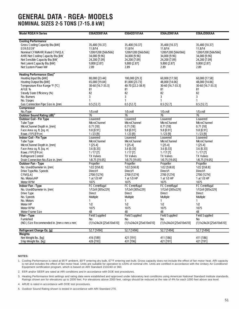
51
GENERAL DATA - RGEA- MODELSNOMINAL SIZES 2-5 TONS [7-15.8 kW]
Model RGEA14 Series 036ADD081AA 036ADD101AA 036AJD061AA 036AJD06XAA
Net System Power kW 2.89 2.89 2.89 2.89
(NO.) Size Recommended in. [mm x mm x mm] (1)1x24x24 [25x610x610] (1)1x24x24 [25x610x610] (1)1x24x24 [25x610x610] (1)1x24x24 [25x610x610]
Ship Weight lbs. [kg] 426 [193] 431 [196] 421 [191] 421 [191]
1Cooling Performance Continued -> Gross Cooling Capacity Btu [kW]
235,400 [10.37] 35,400 [10.37] 35,400 [10.37] 35,400 [10.37]
EER/SEER 11.8/14 11.8/14 11.8/14 11.8/14 Nominal CFM/AHRI Rated CFM [L/s] 1200/1200 [566/566] 1200/1200 [566/566] 1200/1200 [566/566] 1200/1200 [566/566] AHRI Net Cooling Capacity Btu [kW] 34,000 [9.96] 34,000 [9.96] 34,000 [9.96] 34,000 [9.96] Net Sensible Capacity Btu [kW] 24,200 [7.09] 24,200 [7.09] 24,200 [7.09] 24,200 [7.09] Net Latent Capacity Btu [kW] 9,800 [2.87] 9,800 [2.87] 9,800 [2.87] 9,800 [2.87]
4Heating Performance (Gas) Heating Input Btu [kW] 80,000 [23.44] 100,000 [29.3] 60,000 [17.58] 60,000 [17.58] Heating Output Btu [kW] 65,000 [19.04] 81,000 [23.73] 48,000 [14.06] 48,000 [14.06] Temperature Rise Range ºF [ºC] 30-60 [16.7-33.3] 40-70 [22.2-38.9] 30-60 [16.7-33.3] 30-60 [16.7-33.3] AFUE % 81 81 81 81 Steady State Efficiency (%) 82 82 82 82 No. Burners 3 3 3 3 No. Stages 1 1 1 1 Gas Connection Pipe Size in. [mm] 0.5 [12.7] 0.5 [12.7] 0.5 [12.7] 0.5 [12.7]Compressor No./Type
51/Scroll 1/Scroll 1/Scroll 1/Scroll
Outdoor Sound Rating (dB) 76 76 76 76Outdoor Coil - Fin Type Louvered Louvered Louvered Louvered Tube Type MicroChannel MicroChannel MicroChannel MicroChannel MicroChannel Depth in. [mm] 0.71 [18] 0.71 [18] 0.71 [18] 0.71 [18] Face Area sq. ft. [sq. m] 9.8 [0.91] 9.8 [0.91] 9.8 [0.91] 9.8 [0.91] Rows / FPI [FPcm] 1 / 23 [9] 1 / 23 [9] 1 / 23 [9] 1 / 23 [9]Indoor Coil - Fin Type Louvered Louvered Louvered Louvered Tube Type MicroChannel MicroChannel MicroChannel MicroChannel MicroChannel Depth in. [mm] 1 [25.4] 1 [25.4] 1 [25.4] 1 [25.4] Face Area sq. ft. [sq. m] 3.6 [0.33] 3.6 [0.33] 3.6 [0.33] 3.6 [0.33] Rows / FPI [FPcm] 1 / 17 [7] 1 / 17 [7] 1 / 17 [7] 1 / 17 [7] Refrigerant Control TX Valves TX Valves TX Valves TX Valves Drain Connection No./Size in. [mm] 1/0.75 [19.05] 1/0.75 [19.05] 1/0.75 [19.05] 1/0.75 [19.05]Outdoor Fan - Type Propeller Propeller Propeller Propeller No. Used/Diameter in. [mm] 1/22 [558.8] 1/22 [558.8] 1/22 [558.8] 1/22 [558.8] Drive Type/No. Speeds Direct/1 Direct/1 Direct/1 Direct/1 CFM [L/s] 2700 [1274] 2700 [1274] 2700 [1274] 2700 [1274] No. Motors/HP 1 at 1/3 HP 1 at 1/3 HP 1 at 1/3 HP 1 at 1/3 HP Motor RPM 1075 1075 1075 1075Indoor Fan - Type FC Centrifugal FC Centrifugal FC Centrifugal FC Centrifugal No. Used/Diameter in. [mm] 1/12x9 [305x229] 1/12x9 [305x229] 1/12x9 [305x229] 1/12x9 [305x229] Drive Type Direct Direct Direct Direct No. Speeds Multiple Multiple Multiple Multiple No. Motors 1 1 1 1 Motor HP 1/2 1/2 1/2 1/2 Motor RPM 1075 1075 1075 1075 Motor Frame Size 48 48 48 48Filter - Type Field Supplied Field Supplied Field Supplied Field Supplied Furnished No No No No
Refrigerant Charge Oz. [g] 52.7 [1494] 52.7 [1494] 52.7 [1494] 52.7 [1494]Weights Net Weight lbs. [kg] 416 [189] 421 [191] 411 [186] 411 [186]
NOTES:
1. Cooling Performance is rated at 95°F ambient, 80°F entering dry bulb, 67°F entering wet bulb. Gross capacity does not include the effect of fan motor heat. ARI capacityis net and includes the effect of fan motor heat. Units are suitable for operation to ±20% of nominal cfm. Units are certified in accordance with the Unitary Air ConditionerEquipment certification program, which is based on ARI Standard 210/240 or 360.
2. EER and/or SEER are rated at ARI conditions and in accordance with DOE test procedures.
3. Heating Performance limit settings and rating data were established and approved under laboratory test conditions using American National Standard Institute standards.Ratings shown are for elevations up to 2000 feet. For elevations above 2000 feet, ratings should be reduced at the rate of 4% for each 1000 feet above sea level.
4. ARUE is rated in accordance with DOE test procedures.
5. Outdoor Sound Rating shown is tested in accordance with ARI Standard 270.

52
GENERAL DATA - RGEA- MODELSNOMINAL SIZES 2-5 TONS [7-15.8 kW]
Model RGEA14 Series 036AJD081AA 036AJD08XAA 036AJD101AA 036AJD10XAA
Net System Power kW 2.89 2.89 2.89 2.89
(NO.) Size Recommended in. [mm x mm x mm] (1)1x24x24 [25x610x610] (1)1x24x24 [25x610x610] (1)1x24x24 [25x610x610] (1)1x24x24 [25x610x610]
Ship Weight lbs. [kg] 426 [193] 426 [193] 431 [196] 431 [196]
Cooling Performance1 Continued -> Gross Cooling Capacity Btu [kW] 35,400 [10.37] 35,400 [10.37] 35,400 [10.37] 35,400 [10.37] EER/SEER2 11.8/14 11.8/14 11.8/14 11.8/14 Nominal CFM/AHRI Rated CFM [L/s] 1200/1200 [566/566] 1200/1200 [566/566] 1200/1200 [566/566] 1200/1200 [566/566] AHRI Net Cooling Capacity Btu [kW] 34,000 [9.96] 34,000 [9.96] 34,000 [9.96] 34,000 [9.96] Net Sensible Capacity Btu [kW] 24,200 [7.09] 24,200 [7.09] 24,200 [7.09] 24,200 [7.09] Net Latent Capacity Btu [kW] 9,800 [2.87] 9,800 [2.87] 9,800 [2.87] 9,800 [2.87]
Heating Performance (Gas)4
Heating Input Btu [kW] 80,000 [23.44] 80,000 [23.44] 100,000 [29.3] 100,000 [29.3] Heating Output Btu [kW] 65,000 [19.04] 65,000 [19.04] 81,000 [23.73] 81,000 [23.73] Temperature Rise Range ºF [ºC] 30-60 [16.7-33.3] 30-60 [16.7-33.3] 40-70 [22.2-38.9] 40-70 [22.2-38.9] AFUE % 81 81 81 81 Steady State Efficiency (%) 82 82 82 82 No. Burners 3 3 3 3 No. Stages 1 1 1 1 Gas Connection Pipe Size in. [mm] 0.5 [12.7] 0.5 [12.7] 0.5 [12.7] 0.5 [12.7]Compressor No./Type 1/Scroll 1/Scroll 1/Scroll 1/ScrollOutdoor Sound Rating (dB)5 76 76 76 76Outdoor Coil - Fin Type Louvered Louvered Louvered Louvered Tube Type MicroChannel MicroChannel MicroChannel MicroChannel MicroChannel Depth in. [mm] 0.71 [18] 0.71 [18] 0.71 [18] 0.71 [18] Face Area sq. ft. [sq. m] 9.8 [0.91] 9.8 [0.91] 9.8 [0.91] 9.8 [0.91] Rows / FPI [FPcm] 1 / 23 [9] 1 / 23 [9] 1 / 23 [9] 1 / 23 [9]Indoor Coil - Fin Type Louvered Louvered Louvered Louvered Tube Type MicroChannel MicroChannel MicroChannel MicroChannel MicroChannel Depth in. [mm] 1 [25.4] 1 [25.4] 1 [25.4] 1 [25.4] Face Area sq. ft. [sq. m] 3.6 [0.33] 3.6 [0.33] 3.6 [0.33] 3.6 [0.33] Rows / FPI [FPcm] 1 / 17 [7] 1 / 17 [7] 1 / 17 [7] 1 / 17 [7] Refrigerant Control TX Valves TX Valves TX Valves TX Valves Drain Connection No./Size in. [mm] 1/0.75 [19.05] 1/0.75 [19.05] 1/0.75 [19.05] 1/0.75 [19.05]Outdoor Fan - Type Propeller Propeller Propeller Propeller No. Used/Diameter in. [mm] 1/22 [558.8] 1/22 [558.8] 1/22 [558.8] 1/22 [558.8] Drive Type/No. Speeds Direct/1 Direct/1 Direct/1 Direct/1 CFM [L/s] 2700 [1274] 2700 [1274] 2700 [1274] 2700 [1274] No. Motors/HP 1 at 1/3 HP 1 at 1/3 HP 1 at 1/3 HP 1 at 1/3 HP Motor RPM 1075 1075 1075 1075Indoor Fan - Type FC Centrifugal FC Centrifugal FC Centrifugal FC Centrifugal No. Used/Diameter in. [mm] 1/12x9 [305x229] 1/12x9 [305x229] 1/12x9 [305x229] 1/12x9 [305x229] Drive Type Direct Direct Direct Direct No. Speeds Multiple Multiple Multiple Multiple No. Motors 1 1 1 1 Motor HP 1/2 1/2 1/2 1/2 Motor RPM 1075 1075 1075 1075 Motor Frame Size 48 48 48 48Filter - Type Field Supplied Field Supplied Field Supplied Field Supplied Furnished No No No No
Refrigerant Charge Oz. [g] 52.7 [1494] 52.7 [1494] 52.7 [1494] 52.7 [1494]Weights Net Weight lbs. [kg] 416 [189] 416 [189] 421 [191] 421 [191]
NOTES:
1. Cooling Performance is rated at 95°F ambient, 80°F entering dry bulb, 67°F entering wet bulb. Gross capacity does not include the effect of fan motor heat. ARI capacityis net and includes the effect of fan motor heat. Units are suitable for operation to ±20% of nominal cfm. Units are certified in accordance with the Unitary Air ConditionerEquipment certification program, which is based on ARI Standard 210/240 or 360.
2. EER and/or SEER are rated at ARI conditions and in accordance with DOE test procedures.
3. Heating Performance limit settings and rating data were established and approved under laboratory test conditions using American National Standard Institute standards.Ratings shown are for elevations up to 2000 feet. For elevations above 2000 feet, ratings should be reduced at the rate of 4% for each 1000 feet above sea level.
4. ARUE is rated in accordance with DOE test procedures.
5. Outdoor Sound Rating shown is tested in accordance with ARI Standard 270.

53
GENERAL DATA - RGEA- MODELSNOMINAL SIZES 2-5 TONS [7-15.8 kW]
Model RGEA14 Series 042ACT081AA 042ACT101AA 042AJT081AA 042AJT08XAA
Net System Power kW 3.27 3.27 3.27 3.27
(NO.) Size Recommended in. [mm x mm x mm] (1)1x24x24 [25x610x610] (1)1x24x24 [25x610x610] (1)1x24x24 [25x610x610] (1)1x24x24 [25x610x610]
Ship Weight lbs. [kg] 451 [205] 456 [207] 451 [205] 451 [205]
Cooling Performance1 Continued -> Gross Cooling Capacity Btu [kW] 41,000 [12.01] 41,000 [12.01] 41,000 [12.01] 41,000 [12.01] EER/SEER2 12/14 12/14 12/14 12/14 Nominal CFM/AHRI Rated CFM [L/s] 1400/1300 [661/613] 1400/1300 [661/613] 1400/1300 [661/613] 1400/1300 [661/613] AHRI Net Cooling Capacity Btu [kW] 40,000 [11.72] 40,000 [11.72] 40,000 [11.72] 40,000 [11.72] Net Sensible Capacity Btu [kW] 29,000 [8.5] 29,000 [8.5] 29,000 [8.5] 29,000 [8.5] Net Latent Capacity Btu [kW] 11,000 [3.22] 11,000 [3.22] 11,000 [3.22] 11,000 [3.22]
Heating Performance (Gas)4
Heating Input Btu [kW] 80,000 [23.44] 100,000 [29.3] 80,000 [23.44] 80,000 [23.44] Heating Output Btu [kW] 65,000 [19.04] 81,000 [23.73] 65,000 [19.04] 65,000 [19.04] Temperature Rise Range ºF [ºC] 35-65 [19.4-36.1] 45-75 [25-41.7] 35-65 [19.4-36.1] 35-65 [19.4-36.1] AFUE % 81 81 81 81 Steady State Efficiency (%) 82 82 82 82 No. Burners 4 4 4 4 No. Stages 1 1 1 1 Gas Connection Pipe Size in. [mm] 0.5 [12.7] 0.5 [12.7] 0.5 [12.7] 0.5 [12.7]Compressor No./Type 1/Scroll 1/Scroll 1/Scroll 1/ScrollOutdoor Sound Rating (dB)5 76 76 76 76Outdoor Coil - Fin Type Louvered Louvered Louvered Louvered Tube Type MicroChannel MicroChannel MicroChannel MicroChannel MicroChannel Depth in. [mm] 0.71 [18] 0.71 [18] 0.71 [18] 0.71 [18] Face Area sq. ft. [sq. m] 14.1 [1.31] 14.1 [1.31] 14.1 [1.31] 14.1 [1.31] Rows / FPI [FPcm] 1 / 23 [9] 1 / 23 [9] 1 / 23 [9] 1 / 23 [9]Indoor Coil - Fin Type Louvered Louvered Louvered Louvered Tube Type MicroChannel MicroChannel MicroChannel MicroChannel MicroChannel Depth in. [mm] 1 [25.4] 1 [25.4] 1 [25.4] 1 [25.4] Face Area sq. ft. [sq. m] 3.6 [0.33] 3.6 [0.33] 3.6 [0.33] 3.6 [0.33] Rows / FPI [FPcm] 1 / 17 [7] 1 / 17 [7] 1 / 17 [7] 1 / 17 [7] Refrigerant Control TX Valves TX Valves TX Valves TX Valves Drain Connection No./Size in. [mm] 1/0.75 [19.05] 1/0.75 [19.05] 1/0.75 [19.05] 1/0.75 [19.05]Outdoor Fan - Type Propeller Propeller Propeller Propeller No. Used/Diameter in. [mm] 1/22 [558.8] 1/22 [558.8] 1/22 [558.8] 1/22 [558.8] Drive Type/No. Speeds Direct/1 Direct/1 Direct/1 Direct/1 CFM [L/s] 3500 [1652] 3500 [1652] 3500 [1652] 3500 [1652] No. Motors/HP 1 at 1/3 HP 1 at 1/3 HP 1 at 1/3 HP 1 at 1/3 HP Motor RPM 1075 1075 1075 1075Indoor Fan - Type FC Centrifugal FC Centrifugal FC Centrifugal FC Centrifugal No. Used/Diameter in. [mm] 1/12x9 [305x229] 1/12x9 [305x229] 1/12x9 [305x229] 1/12x9 [305x229] Drive Type Direct Direct Direct Direct No. Speeds Multiple Multiple Multiple Multiple No. Motors 1 1 1 1 Motor HP 3/4 3/4 3/4 3/4 Motor RPM 1075 1075 1075 1075 Motor Frame Size 48 48 48 48Filter - Type Field Supplied Field Supplied Field Supplied Field Supplied Furnished No No No No
Refrigerant Charge Oz. [g] 53.6 [1520] 53.6 [1520] 53.6 [1520] 53.6 [1520]Weights Net Weight lbs. [kg] 441 [200] 446 [202] 441 [200] 441 [200]
NOTES:
1. Cooling Performance is rated at 95°F ambient, 80°F entering dry bulb, 67°F entering wet bulb. Gross capacity does not include the effect of fan motor heat. ARI capacityis net and includes the effect of fan motor heat. Units are suitable for operation to ±20% of nominal cfm. Units are certified in accordance with the Unitary Air ConditionerEquipment certification program, which is based on ARI Standard 210/240 or 360.
2. EER and/or SEER are rated at ARI conditions and in accordance with DOE test procedures.
3. Heating Performance limit settings and rating data were established and approved under laboratory test conditions using American National Standard Institute standards.Ratings shown are for elevations up to 2000 feet. For elevations above 2000 feet, ratings should be reduced at the rate of 4% for each 1000 feet above sea level.
4. ARUE is rated in accordance with DOE test procedures.
5. Outdoor Sound Rating shown is tested in accordance with ARI Standard 270.

54
GENERAL DATA - RGEA- MODELSNOMINAL SIZES 2-5 TONS [7-15.8 kW]
Model RGEA14 Series 042AJT101AA 042AJT10XAA 048ACT081AA 048ACT101AA
Net System Power kW 3.27 3.27 3.89 3.89
Furnished No No No No
Ship Weight lbs. [kg] 456 [207] 456 [207] 487 [221] 492 [223]
Cooling Performance1 Continued -> Gross Cooling Capacity Btu [kW] 41,000 [12.01] 41,000 [12.01] 47,500 [13.92] 47,500 [13.92] EER/SEER2 12/14 12/14 11.7/14 11.7/14 Nominal CFM/AHRI Rated CFM [L/s] 1400/1300 [661/613] 1400/1300 [661/613] 1600/1550 [755/731] 1600/1550 [755/731] AHRI Net Cooling Capacity Btu [kW] 40,000 [11.72] 40,000 [11.72] 46,000 [13.48] 46,000 [13.48] Net Sensible Capacity Btu [kW] 29,000 [8.5] 29,000 [8.5] 32,500 [9.52] 32,500 [9.52] Net Latent Capacity Btu [kW] 11,000 [3.22] 11,000 [3.22] 13,500 [3.96] 13,500 [3.96]
Heating Performance (Gas)4
Heating Input Btu [kW] 100,000 [29.3] 100,000 [29.3] 80,000 [23.44] 100,000 [29.3] Heating Output Btu [kW] 81,000 [23.73] 81,000 [23.73] 65,000 [19.04] 81,000 [23.73] Temperature Rise Range ºF [ºC] 45-75 [25-41.7] 45-75 [25-41.7] 35-65 [19.4-36.1] 45-75 [25-41.7] AFUE % 81 81 81 81 Steady State Efficiency (%) 82 82 82 82 No. Burners 4 4 4 4 No. Stages 1 1 1 1 Gas Connection Pipe Size in. [mm] 0.5 [12.7] 0.5 [12.7] 0.5 [12.7] 0.5 [12.7]Compressor No./Type 1/Scroll 1/Scroll 1/Scroll 1/ScrollOutdoor Sound Rating (dB)5 76 76 78 78Outdoor Coil - Fin Type Louvered Louvered Louvered Louvered Tube Type MicroChannel MicroChannel MicroChannel MicroChannel MicroChannel Depth in. [mm] 0.71 [18] 0.71 [18] 0.71 [18] 0.71 [18] Face Area sq. ft. [sq. m] 14.1 [1.31] 14.1 [1.31] 16.3 [1.51] 16.3 [1.51] Rows / FPI [FPcm] 1 / 23 [9] 1 / 23 [9] 1 / 23 [9] 1 / 23 [9]Indoor Coil - Fin Type Louvered Louvered Louvered Louvered Tube Type MicroChannel MicroChannel MicroChannel MicroChannel MicroChannel Depth in. [mm] 1 [25.4] 1 [25.4] 1 [25.4] 1 [25.4] Face Area sq. ft. [sq. m] 3.6 [0.33] 3.6 [0.33] 4.1 [0.38] 4.1 [0.38] Rows / FPI [FPcm] 1 / 17 [7] 1 / 17 [7] 1 / 20 [8] 1 / 20 [8] Refrigerant Control TX Valves TX Valves TX Valves TX Valves Drain Connection No./Size in. [mm] 1/0.75 [19.05] 1/0.75 [19.05] 1/0.75 [19.05] 1/0.75 [19.05]Outdoor Fan - Type Propeller Propeller Propeller Propeller No. Used/Diameter in. [mm] 1/22 [558.8] 1/22 [558.8] 1/22 [558.8] 1/22 [558.8] Drive Type/No. Speeds Direct/1 Direct/1 Direct/1 Direct/1 CFM [L/s] 3500 [1652] 3500 [1652] 3300 [1557] 3300 [1557] No. Motors/HP 1 at 1/3 HP 1 at 1/3 HP 1 at 1/3 HP 1 at 1/3 HP Motor RPM 1075 1075 1075 1075Indoor Fan - Type FC Centrifugal FC Centrifugal FC Centrifugal FC Centrifugal No. Used/Diameter in. [mm] 1/12x9 [305x229] 1/12x9 [305x229] 1/12x9 [305x229] 1/12x9 [305x229] Drive Type Direct Direct Direct Direct No. Speeds Multiple Multiple Multiple Multiple No. Motors 1 1 1 1 Motor HP 3/4 3/4 3/4 3/4 Motor RPM 1075 1075 1075 1075 Motor Frame Size 48 48 48 48Filter - Type Field Supplied Field Supplied Field Supplied Field Supplied
(NO.) Size Recommended in. [mm x mm x mm] (1)1x24x24 [25x610x610] (1)1x24x24 [25x610x610] (1)1x24x24 [25x610x610] (1)1x24x24 [25x610x610]
Refrigerant Charge Oz. [g] 53.6 [1520] 53.6 [1520] 69.3 [1965] 69.3 [1965]Weights Net Weight lbs. [kg] 446 [202] 446 [202] 477 [216] 482 [219]
NOTES:
1. Cooling Performance is rated at 95°F ambient, 80°F entering dry bulb, 67°F entering wet bulb. Gross capacity does not include the effect of fan motor heat. ARI capacityis net and includes the effect of fan motor heat. Units are suitable for operation to ±20% of nominal cfm. Units are certified in accordance with the Unitary Air ConditionerEquipment certification program, which is based on ARI Standard 210/240 or 360.
2. EER and/or SEER are rated at ARI conditions and in accordance with DOE test procedures.
3. Heating Performance limit settings and rating data were established and approved under laboratory test conditions using American National Standard Institute standards.Ratings shown are for elevations up to 2000 feet. For elevations above 2000 feet, ratings should be reduced at the rate of 4% for each 1000 feet above sea level.
4. ARUE is rated in accordance with DOE test procedures.
5. Outdoor Sound Rating shown is tested in accordance with ARI Standard 270.

55
GENERAL DATA - RGEA- MODELSNOMINAL SIZES 2-5 TONS [7-15.8 kW]
Net Latent Capacity Btu [kW] 13,500 [3.96] 13,500 [3.96] 13,500 [3.96] 13,500 [3.96]
Furnished No No No No
Net Weight lbs. [kg] 482 [219] 477 [216] 477 [216] 482 [219] Ship Weight lbs. [kg] 492 [223] 487 [221] 487 [221] 492 [223]
Model RGEA14 Series 048ADT101AA 048AJT081AA 048AJT08XAA 048AJT101AA
1Cooling Performance Continued -> Gross Cooling Capacity Btu [kW]
247,500 [13.92] 47,500 [13.92] 47,500 [13.92] 47,500 [13.92]
EER/SEER 11.7/14 11.7/14 11.7/14 11.7/14 Nominal CFM/AHRI Rated CFM [L/s] 1600/1550 [755/731] 1600/1550 [755/731] 1600/1550 [755/731] 1600/1550 [755/731] AHRI Net Cooling Capacity Btu [kW] 46,000 [13.48] 46,000 [13.48] 46,000 [13.48] 46,000 [13.48] Net Sensible Capacity Btu [kW] 32,500 [9.52] 32,500 [9.52] 32,500 [9.52] 32,500 [9.52]
Net System Power kW 3.89 3.89 3.89 3.89
4Heating Performance (Gas) Heating Input Btu [kW] 100,000 [29.3] 80,000 [23.44] 80,000 [23.44] 100,000 [29.3] Heating Output Btu [kW] 81,000 [23.73] 65,000 [19.04] 65,000 [19.04] 81,000 [23.73] Temperature Rise Range ºF [ºC] 45-75 [25-41.7] 35-65 [19.4-36.1] 35-65 [19.4-36.1] 45-75 [25-41.7] AFUE % 81 81 81 81 Steady State Efficiency (%) 82 82 82 82 No. Burners 4 4 4 4 No. Stages 1 1 1 1 Gas Connection Pipe Size in. [mm] 0.5 [12.7] 0.5 [12.7] 0.5 [12.7] 0.5 [12.7]Compressor No./Type
51/Scroll 1/Scroll 1/Scroll 1/Scroll
Outdoor Sound Rating (dB) 78 78 78 78Outdoor Coil - Fin Type Louvered Louvered Louvered Louvered Tube Type MicroChannel MicroChannel MicroChannel MicroChannel MicroChannel Depth in. [mm] 0.71 [18] 0.71 [18] 0.71 [18] 0.71 [18] Face Area sq. ft. [sq. m] 16.3 [1.51] 16.3 [1.51] 16.3 [1.51] 16.3 [1.51] Rows / FPI [FPcm] 1 / 23 [9] 1 / 23 [9] 1 / 23 [9] 1 / 23 [9]Indoor Coil - Fin Type Louvered Louvered Louvered Louvered Tube Type MicroChannel MicroChannel MicroChannel MicroChannel MicroChannel Depth in. [mm] 1 [25.4] 1 [25.4] 1 [25.4] 1 [25.4] Face Area sq. ft. [sq. m] 4.1 [0.38] 4.1 [0.38] 4.1 [0.38] 4.1 [0.38] Rows / FPI [FPcm] 1 / 20 [8] 1 / 20 [8] 1 / 20 [8] 1 / 20 [8] Refrigerant Control TX Valves TX Valves TX Valves TX Valves Drain Connection No./Size in. [mm] 1/0.75 [19.05] 1/0.75 [19.05] 1/0.75 [19.05] 1/0.75 [19.05]Outdoor Fan - Type Propeller Propeller Propeller Propeller No. Used/Diameter in. [mm] 1/22 [558.8] 1/22 [558.8] 1/22 [558.8] 1/22 [558.8] Drive Type/No. Speeds Direct/1 Direct/1 Direct/1 Direct/1 CFM [L/s] 3300 [1557] 3300 [1557] 3300 [1557] 3300 [1557] No. Motors/HP 1 at 1/3 HP 1 at 1/3 HP 1 at 1/3 HP 1 at 1/3 HP Motor RPM 1075 1075 1075 1075Indoor Fan - Type FC Centrifugal FC Centrifugal FC Centrifugal FC Centrifugal No. Used/Diameter in. [mm] 1/12x9 [305x229] 1/12x9 [305x229] 1/12x9 [305x229] 1/12x9 [305x229] Drive Type Direct Direct Direct Direct No. Speeds Multiple Multiple Multiple Multiple No. Motors 1 1 1 1 Motor HP 3/4 3/4 3/4 3/4 Motor RPM 1075 1075 1075 1075 Motor Frame Size 48 48 48 48Filter - Type Field Supplied Field Supplied Field Supplied Field Supplied
(NO.) Size Recommended in. [mm x mm x mm] (1)1x24x24 [25x610x610] (1)1x24x24 [25x610x610] (1)1x24x24 [25x610x610] (1)1x24x24 [25x610x610]
Refrigerant Charge Oz. [g] 69.3 [1965] 69.3 [1965] 69.3 [1965] 69.3 [1965]Weights
NOTES:
1. Cooling Performance is rated at 95°F ambient, 80°F entering dry bulb, 67°F entering wet bulb. Gross capacity does not include the effect of fan motor heat. ARI capacityis net and includes the effect of fan motor heat. Units are suitable for operation to ±20% of nominal cfm. Units are certified in accordance with the Unitary Air ConditionerEquipment certification program, which is based on ARI Standard 210/240 or 360.
2. EER and/or SEER are rated at ARI conditions and in accordance with DOE test procedures.
3. Heating Performance limit settings and rating data were established and approved under laboratory test conditions using American National Standard Institute standards.Ratings shown are for elevations up to 2000 feet. For elevations above 2000 feet, ratings should be reduced at the rate of 4% for each 1000 feet above sea level.
4. ARUE is rated in accordance with DOE test procedures.
5. Outdoor Sound Rating shown is tested in accordance with ARI Standard 270.

56
GENERAL DATA - RGEA- MODELSNOMINAL SIZES 2-5 TONS [7-15.8 kW]
Net Latent Capacity Btu [kW] 13,500 [3.96] 17,500 [5.13] 17,500 [5.13] 17,500 [5.13]
Furnished No No No No
Net Weight lbs. [kg] 482 [219] 512 [232] 512 [232] 512 [232] Ship Weight lbs. [kg] 492 [223] 522 [237] 522 [237] 522 [237]
Model RGEA14 Series 048AJT10XAA 060ACT101AA 060ADT101AA 060AJT101AA
1Cooling Performance Continued -> Gross Cooling Capacity Btu [kW]
247,500 [13.92] 59,000 [17.29] 59,000 [17.29] 59,000 [17.29]
EER/SEER 11.7/14 11.6/14 11.6/14 11.6/14 Nominal CFM/AHRI Rated CFM [L/s] 1600/1550 [755/731] 2000/1700 [944/802] 2000/1700 [944/802] 2000/1700 [944/802] AHRI Net Cooling Capacity Btu [kW] 46,000 [13.48] 57,000 [16.7] 57,000 [16.7] 57,000 [16.7] Net Sensible Capacity Btu [kW] 32,500 [9.52] 39,500 [11.57] 39,500 [11.57] 39,500 [11.57]
Net System Power kW 3.89 4.94 4.94 4.94
4Heating Performance (Gas) Heating Input Btu [kW] 100,000 [29.3] 100,000 [29.3] 100,000 [29.3] 100,000 [29.3] Heating Output Btu [kW] 81,000 [23.73] 81,000 [23.73] 81,000 [23.73] 81,000 [23.73] Temperature Rise Range ºF [ºC] 45-75 [25-41.7] 45-75 [25-41.7] 45-75 [25-41.7] 45-75 [25-41.7] AFUE % 81 81 81 81 Steady State Efficiency (%) 82 82 82 82 No. Burners 4 5 5 5 No. Stages 1 1 1 1 Gas Connection Pipe Size in. [mm] 0.5 [12.7] 0.5 [12.7] 0.5 [12.7] 0.5 [12.7]Compressor No./Type 1/Scroll 1/Scroll 1/Scroll 1/ScrollOutdoor Sound Rating (dB)5 78 79 79 79Outdoor Coil - Fin Type Louvered Louvered Louvered Louvered Tube Type MicroChannel MicroChannel MicroChannel MicroChannel MicroChannel Depth in. [mm] 0.71 [18] 1 [25.4] 1 [25.4] 1 [25.4] Face Area sq. ft. [sq. m] 16.3 [1.51] 15.3 [1.42] 15.3 [1.42] 15.3 [1.42] Rows / FPI [FPcm] 1 / 23 [9] 1 / 23 [9] 1 / 23 [9] 1 / 23 [9]Indoor Coil - Fin Type Louvered Louvered Louvered Louvered Tube Type MicroChannel MicroChannel MicroChannel MicroChannel MicroChannel Depth in. [mm] 1 [25.4] 1.26 [32] 1.26 [32] 1.26 [32] Face Area sq. ft. [sq. m] 4.1 [0.38] 4 [0.37] 4 [0.37] 4 [0.37] Rows / FPI [FPcm] 1 / 20 [8] 1 / 20 [8] 1 / 20 [8] 1 / 20 [8] Refrigerant Control TX Valves TX Valves TX Valves TX Valves Drain Connection No./Size in. [mm] 1/0.75 [19.05] 1/0.75 [19.05] 1/0.75 [19.05] 1/0.75 [19.05]Outdoor Fan - Type Propeller Propeller Propeller Propeller No. Used/Diameter in. [mm] 1/22 [558.8] 1/22 [558.8] 1/22 [558.8] 1/22 [558.8] Drive Type/No. Speeds Direct/1 Direct/1 Direct/1 Direct/1 CFM [L/s] 3300 [1557] 3400 [1604] 3400 [1604] 3400 [1604] No. Motors/HP 1 at 1/3 HP 1 at 1/3 HP 1 at 1/3 HP 1 at 1/3 HP Motor RPM 1075 1075 1075 1075Indoor Fan - Type FC Centrifugal FC Centrifugal FC Centrifugal FC Centrifugal No. Used/Diameter in. [mm] 1/12x9 [305x229] 1/12x9 [305x229] 1/12x9 [305x229] 1/12x9 [305x229] Drive Type Direct Direct Direct Direct No. Speeds Multiple Multiple Multiple Multiple No. Motors 1 1 1 1 Motor HP 3/4 1 1 1 Motor RPM 1075 1075 1075 1075 Motor Frame Size 48 48 48 48Filter - Type Field Supplied Field Supplied Field Supplied Field Supplied
(NO.) Size Recommended in. [mm x mm x mm] (1)1x24x24 [25x610x610] (1)1x24x30 [25x610x762] (1)1x24x30 [25x610x762] (1)1x24x30 [25x610x762]
Refrigerant Charge Oz. [g] 69.3 [1965] 83.1 [2356] 83.1 [2356] 83.1 [2356]Weights
NOTES:
1. Cooling Performance is rated at 95°F ambient, 80°F entering dry bulb, 67°F entering wet bulb. Gross capacity does not include the effect of fan motor heat. ARI capacityis net and includes the effect of fan motor heat. Units are suitable for operation to ±20% of nominal cfm. Units are certified in accordance with the Unitary Air ConditionerEquipment certification program, which is based on ARI Standard 210/240 or 360.
2. EER and/or SEER are rated at ARI conditions and in accordance with DOE test procedures.
3. Heating Performance limit settings and rating data were established and approved under laboratory test conditions using American National Standard Institute standards.Ratings shown are for elevations up to 2000 feet. For elevations above 2000 feet, ratings should be reduced at the rate of 4% for each 1000 feet above sea level.
4. ARUE is rated in accordance with DOE test procedures.
5. Outdoor Sound Rating shown is tested in accordance with ARI Standard 270.
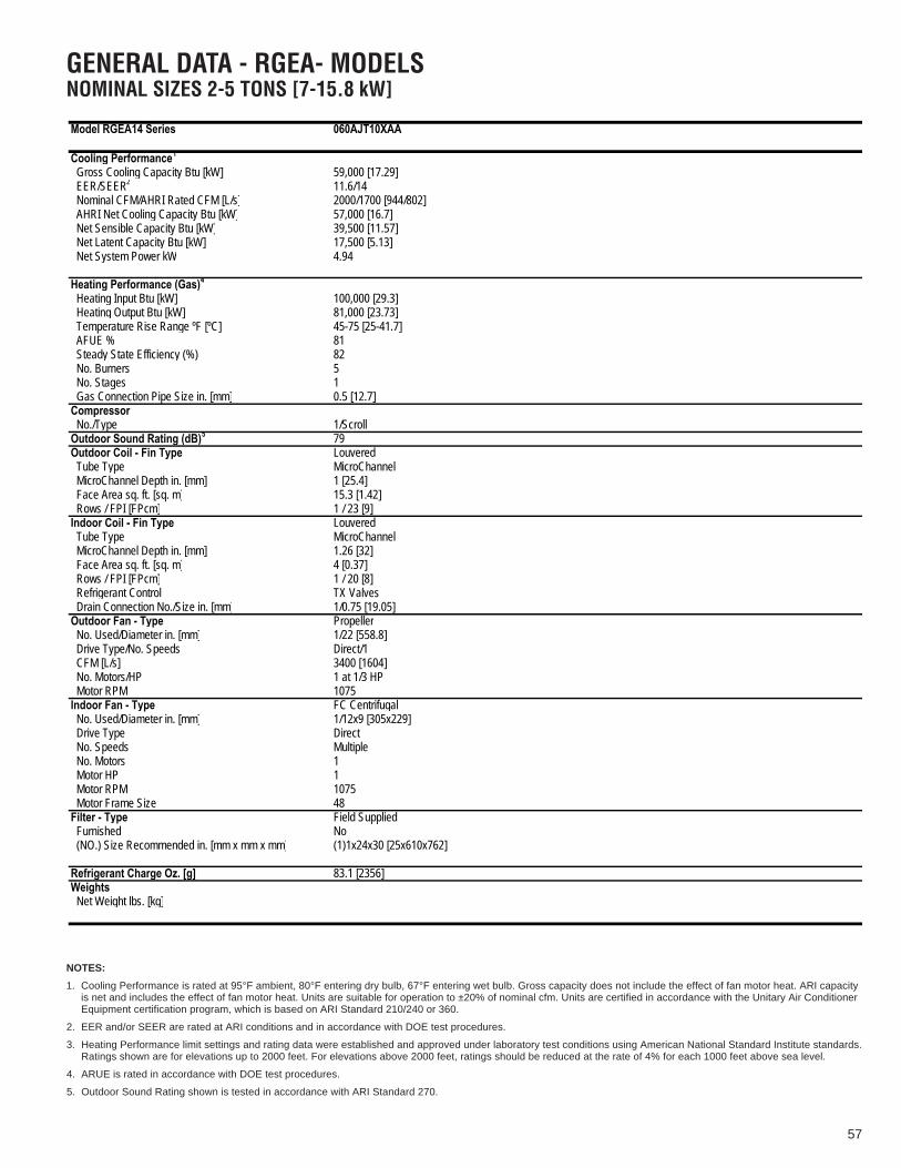
57
GENERAL DATA - RGEA- MODELSNOMINAL SIZES 2-5 TONS [7-15.8 kW]
Net Latent Capacity Btu [kW] 17,500 [5.13]
Filter - Type Field Supplied
Weights Net Weight lbs. [kg]
Model RGEA14 Series 060AJT10XAA
Cooling Performance1
Gross Cooling Capacity Btu [kW] 59,000 [17.29] EER/SEER2 11.6/14 Nominal CFM/AHRI Rated CFM [L/s] 2000/1700 [944/802] AHRI Net Cooling Capacity Btu [kW] 57,000 [16.7] Net Sensible Capacity Btu [kW] 39,500 [11.57]
Net System Power kW 4.94
Heating Performance (Gas)4
Heating Input Btu [kW] 100,000 [29.3] Heating Output Btu [kW] 81,000 [23.73] Temperature Rise Range ºF [ºC] 45-75 [25-41.7] AFUE % 81 Steady State Efficiency (%) 82 No. Burners 5 No. Stages 1 Gas Connection Pipe Size in. [mm] 0.5 [12.7]Compressor No./Type
51/Scroll
Outdoor Sound Rating (dB) 79Outdoor Coil - Fin Type Louvered Tube Type MicroChannel MicroChannel Depth in. [mm] 1 [25.4] Face Area sq. ft. [sq. m] 15.3 [1.42] Rows / FPI [FPcm] 1 / 23 [9]Indoor Coil - Fin Type Louvered Tube Type MicroChannel MicroChannel Depth in. [mm] 1.26 [32] Face Area sq. ft. [sq. m] 4 [0.37] Rows / FPI [FPcm] 1 / 20 [8] Refrigerant Control TX Valves Drain Connection No./Size in. [mm] 1/0.75 [19.05]Outdoor Fan - Type Propeller No. Used/Diameter in. [mm] 1/22 [558.8] Drive Type/No. Speeds Direct/1 CFM [L/s] 3400 [1604] No. Motors/HP 1 at 1/3 HP Motor RPM 1075Indoor Fan - Type FC Centrifugal No. Used/Diameter in. [mm] 1/12x9 [305x229] Drive Type Direct No. Speeds Multiple No. Motors 1 Motor HP 1 Motor RPM 1075 Motor Frame Size 48
Furnished No (NO.) Size Recommended in. [mm x mm x mm] (1)1x24x30 [25x610x762]
Refrigerant Charge Oz. [g] 83.1 [2356]
NOTES:
1. Cooling Performance is rated at 95°F ambient, 80°F entering dry bulb, 67°F entering wet bulb. Gross capacity does not include the effect of fan motor heat. ARI capacityis net and includes the effect of fan motor heat. Units are suitable for operation to ±20% of nominal cfm. Units are certified in accordance with the Unitary Air ConditionerEquipment certification program, which is based on ARI Standard 210/240 or 360.
2. EER and/or SEER are rated at ARI conditions and in accordance with DOE test procedures.
3. Heating Performance limit settings and rating data were established and approved under laboratory test conditions using American National Standard Institute standards.Ratings shown are for elevations up to 2000 feet. For elevations above 2000 feet, ratings should be reduced at the rate of 4% for each 1000 feet above sea level.
4. ARUE is rated in accordance with DOE test procedures.
5. Outdoor Sound Rating shown is tested in accordance with ARI Standard 270.

58
GENERAL DATA - RGEA- MODELSNOMINAL SIZES 2-5 TONS [7-15.8 kW]
Model RGEA15 Series 024AJT061AA 024AJT06XAA 024AJT081AA 024AJT08XAA
Cooling Performance1 Continued -> Gross Cooling Capacity Btu [kW] 24,600 [7.21] 24,600 [7.21] 24,600 [7.21] 24,600 [7.21] EER/SEER2 12/15 12/15 12/15 12/15 Nominal CFM/AHRI Rated CFM [L/s] 800/900 [378/425] 800/900 [378/425] 800/900 [378/425] 800/900 [378/425] AHRI Net Cooling Capacity Btu [kW] 24,000 [7.03] 24,000 [7.03] 24,000 [7.03] 24,000 [7.03] Net Sensible Capacity Btu [kW] 18,100 [5.3] 18,100 [5.3] 18,100 [5.3] 18,100 [5.3] Net Latent Capacity Btu [kW] 5,900 [1.73] 5,900 [1.73] 5,900 [1.73] 5,900 [1.73] Net System Power kW 2.03 2.03 2.03 2.03
Heating Performance (Gas) 4
Heating Input Btu [kW] 60,000 [17.58] 60,000 [17.58] 80,000 [23.44] 80,000 [23.44] Heating Output Btu [kW] 48,000 [14.06] 48,000 [14.06] 65,000 [19.04] 65,000 [19.04] Temperature Rise Range ºF [ºC] 40-70 [22.2-38.9] 40-70 [22.2-38.9] 35-65 [19.4-36.1] 35-65 [19.4-36.1] AFUE % 81 81 81 81 Steady State Efficiency (%) 82 82 82 82 No. Burners 2 2 2 2 No. Stages 1 1 1 1 Gas Connection Pipe Size in. [mm] 0.5 [12.7] 0.5 [12.7] 0.5 [12.7] 0.5 [12.7]Compressor No./Type 1/Scroll 1/Scroll 1/Scroll 1/ScrollOutdoor Sound Rating (dB)5 76 76 76 76Outdoor Coil - Fin Type Louvered Louvered Louvered Louvered Tube Type MicroChannel MicroChannel MicroChannel MicroChannel MicroChannel Depth in. [mm] 0.71 [18] 0.71 [18] 0.71 [18] 0.71 [18] Face Area sq. ft. [sq. m] 7.1 [0.66] 7.1 [0.66] 7.1 [0.66] 7.1 [0.66] Rows / FPI [FPcm] 1 / 23 [9] 1 / 23 [9] 1 / 23 [9] 1 / 23 [9]Indoor Coil - Fin Type Louvered Louvered Louvered Louvered Tube Type MicroChannel MicroChannel MicroChannel MicroChannel MicroChannel Depth in. [mm] 1 [25.4] 1 [25.4] 1 [25.4] 1 [25.4] Face Area sq. ft. [sq. m] 3.6 [0.33] 3.6 [0.33] 3.6 [0.33] 3.6 [0.33] Rows / FPI [FPcm] 1 / 17 [7] 1 / 17 [7] 1 / 17 [7] 1 / 17 [7] Refrigerant Control TX Valves TX Valves TX Valves TX Valves Drain Connection No./Size in. [mm] 1/0.75 [19.05] 1/0.75 [19.05] 1/0.75 [19.05] 1/0.75 [19.05]Outdoor Fan - Type Propeller Propeller Propeller Propeller No. Used/Diameter in. [mm] 1/22 [558.8] 1/22 [558.8] 1/22 [558.8] 1/22 [558.8] Drive Type/No. Speeds Direct/1 Direct/1 Direct/1 Direct/1 CFM [L/s] 2500 [1180] 2500 [1180] 2500 [1180] 2500 [1180] No. Motors/HP 1 at 1/3 HP 1 at 1/3 HP 1 at 1/3 HP 1 at 1/3 HP Motor RPM 1075 1075 1075 1075Indoor Fan - Type FC Centrifugal FC Centrifugal FC Centrifugal FC Centrifugal No. Used/Diameter in. [mm] 1/10x9 [254x229] 1/10x9 [254x229] 1/10x9 [254x229] 1/10x9 [254x229] Drive Type Direct Direct Direct Direct No. Speeds Multiple Multiple Multiple Multiple No. Motors 1 1 1 1 Motor HP 1/3 1/3 1/3 1/3 Motor RPM 1075 1075 1075 1075 Motor Frame Size 48 48 48 48Filter - Type Field Supplied Field Supplied Field Supplied Field Supplied Furnished No No No No (NO.) Size Recommended in. [mm x mm x mm] (1)1x20x20 [25x508x508] (1)1x20x20 [25x508x508] (1)1x20x20 [25x508x508] (1)1x20x20 [25x508x508]
Refrigerant Charge Oz. [g] 42.6 [1208] 42.6 [1208] 42.6 [1208] 42.6 [1208]Weights Net Weight lbs. [kg] 403 [183] 403 [183] 408 [185] 408 [185] Ship Weight lbs. [kg] 413 [187] 413 [187] 418 [190] 418 [190]
NOTES:
1. Cooling Performance is rated at 95°F ambient, 80°F entering dry bulb, 67°F entering wet bulb. Gross capacity does not include the effect of fan motor heat. ARI capacityis net and includes the effect of fan motor heat. Units are suitable for operation to ±20% of nominal cfm. Units are certified in accordance with the Unitary Air ConditionerEquipment certification program, which is based on ARI Standard 210/240 or 360.
2. EER and/or SEER are rated at ARI conditions and in accordance with DOE test procedures.
3. Heating Performance limit settings and rating data were established and approved under laboratory test conditions using American National Standard Institute standards.Ratings shown are for elevations up to 2000 feet. For elevations above 2000 feet, ratings should be reduced at the rate of 4% for each 1000 feet above sea level.
4. ARUE is rated in accordance with DOE test procedures.
5. Outdoor Sound Rating shown is tested in accordance with ARI Standard 270.

59
GENERAL DATA - RGEA- MODELSNOMINAL SIZES 2-5 TONS [7-15.8 kW]
Model RGEA15 Series 024AJV061AA 024AJV06XAA 024AJV081AA 024AJV08XAA
Cooling Performance1 Continued -> Gross Cooling Capacity Btu [kW] 24,600 [7.21] 24,600 [7.21] 24,600 [7.21] 24,600 [7.21] EER/SEER2 12/15 12/15 12/15 12/15 Nominal CFM/AHRI Rated CFM [L/s] 800/900 [378/425] 800/900 [378/425] 800/900 [378/425] 800/900 [378/425] AHRI Net Cooling Capacity Btu [kW] 24,000 [7.03] 24,000 [7.03] 24,000 [7.03] 24,000 [7.03] Net Sensible Capacity Btu [kW] 18,100 [5.3] 18,100 [5.3] 18,100 [5.3] 18,100 [5.3] Net Latent Capacity Btu [kW] 5,900 [1.73] 5,900 [1.73] 5,900 [1.73] 5,900 [1.73] Net System Power kW 2.03 2.03 2.03 2.03
Heating Performance (Gas) 4
Heating Input Btu [kW] 60,000 [17.58] 60,000 [17.58] 80,000 [23.44] 80,000 [23.44] Heating Output Btu [kW] 48,000 [14.06] 48,000 [14.06] 65,000 [19.04] 65,000 [19.04] Temperature Rise Range ºF [ºC] 40-70 [22.2-38.9] 40-70 [22.2-38.9] 35-65 [19.4-36.1] 35-65 [19.4-36.1] AFUE % 81 81 81 81 Steady State Efficiency (%) 82 82 82 82 No. Burners 2 2 2 2 No. Stages 1 1 1 1 Gas Connection Pipe Size in. [mm] 0.5 [12.7] 0.5 [12.7] 0.5 [12.7] 0.5 [12.7]Compressor No./Type 1/Scroll 1/Scroll 1/Scroll 1/ScrollOutdoor Sound Rating (dB)5 76 76 76 76Outdoor Coil - Fin Type Louvered Louvered Louvered Louvered Tube Type MicroChannel MicroChannel MicroChannel MicroChannel MicroChannel Depth in. [mm] 0.71 [18] 0.71 [18] 0.71 [18] 0.71 [18] Face Area sq. ft. [sq. m] 7.1 [0.66] 7.1 [0.66] 7.1 [0.66] 7.1 [0.66] Rows / FPI [FPcm] 1 / 23 [9] 1 / 23 [9] 1 / 23 [9] 1 / 23 [9]Indoor Coil - Fin Type Louvered Louvered Louvered Louvered Tube Type MicroChannel MicroChannel MicroChannel MicroChannel MicroChannel Depth in. [mm] 1 [25.4] 1 [25.4] 1 [25.4] 1 [25.4] Face Area sq. ft. [sq. m] 3.6 [0.33] 3.6 [0.33] 3.6 [0.33] 3.6 [0.33] Rows / FPI [FPcm] 1 / 17 [7] 1 / 17 [7] 1 / 17 [7] 1 / 17 [7] Refrigerant Control TX Valves TX Valves TX Valves TX Valves Drain Connection No./Size in. [mm] 1/0.75 [19.05] 1/0.75 [19.05] 1/0.75 [19.05] 1/0.75 [19.05]Outdoor Fan - Type Propeller Propeller Propeller Propeller No. Used/Diameter in. [mm] 1/22 [558.8] 1/22 [558.8] 1/22 [558.8] 1/22 [558.8] Drive Type/No. Speeds Direct/1 Direct/1 Direct/1 Direct/1 CFM [L/s] 2500 [1180] 2500 [1180] 2500 [1180] 2500 [1180] No. Motors/HP 1 at 1/3 HP 1 at 1/3 HP 1 at 1/3 HP 1 at 1/3 HP Motor RPM 1075 1075 1075 1075Indoor Fan - Type FC Centrifugal FC Centrifugal FC Centrifugal FC Centrifugal No. Used/Diameter in. [mm] 1/10x9 [254x229] 1/10x9 [254x229] 1/10x9 [254x229] 1/10x9 [254x229] Drive Type Direct Direct Direct Direct No. Speeds Multiple Multiple Multiple Multiple No. Motors 1 1 1 1 Motor HP 1/2 1/2 1/2 1/2 Motor RPM 1050 1050 1050 1050 Motor Frame Size 48 48 48 48Filter - Type Field Supplied Field Supplied Field Supplied Field Supplied Furnished No No No No (NO.) Size Recommended in. [mm x mm x mm] (1)1x20x20 [25x508x508] (1)1x20x20 [25x508x508] (1)1x20x20 [25x508x508] (1)1x20x20 [25x508x508]
Refrigerant Charge Oz. [g] 42.6 [1208] 42.6 [1208] 42.6 [1208] 42.6 [1208]Weights Net Weight lbs. [kg] 403 [183] 403 [183] 408 [185] 408 [185] Ship Weight lbs. [kg] 413 [187] 413 [187] 418 [190] 418 [190]
NOTES:
1. Cooling Performance is rated at 95°F ambient, 80°F entering dry bulb, 67°F entering wet bulb. Gross capacity does not include the effect of fan motor heat. ARI capacityis net and includes the effect of fan motor heat. Units are suitable for operation to ±20% of nominal cfm. Units are certified in accordance with the Unitary Air ConditionerEquipment certification program, which is based on ARI Standard 210/240 or 360.
2. EER and/or SEER are rated at ARI conditions and in accordance with DOE test procedures.
3. Heating Performance limit settings and rating data were established and approved under laboratory test conditions using American National Standard Institute standards.Ratings shown are for elevations up to 2000 feet. For elevations above 2000 feet, ratings should be reduced at the rate of 4% for each 1000 feet above sea level.
4. ARUE is rated in accordance with DOE test procedures.
5. Outdoor Sound Rating shown is tested in accordance with ARI Standard 270.
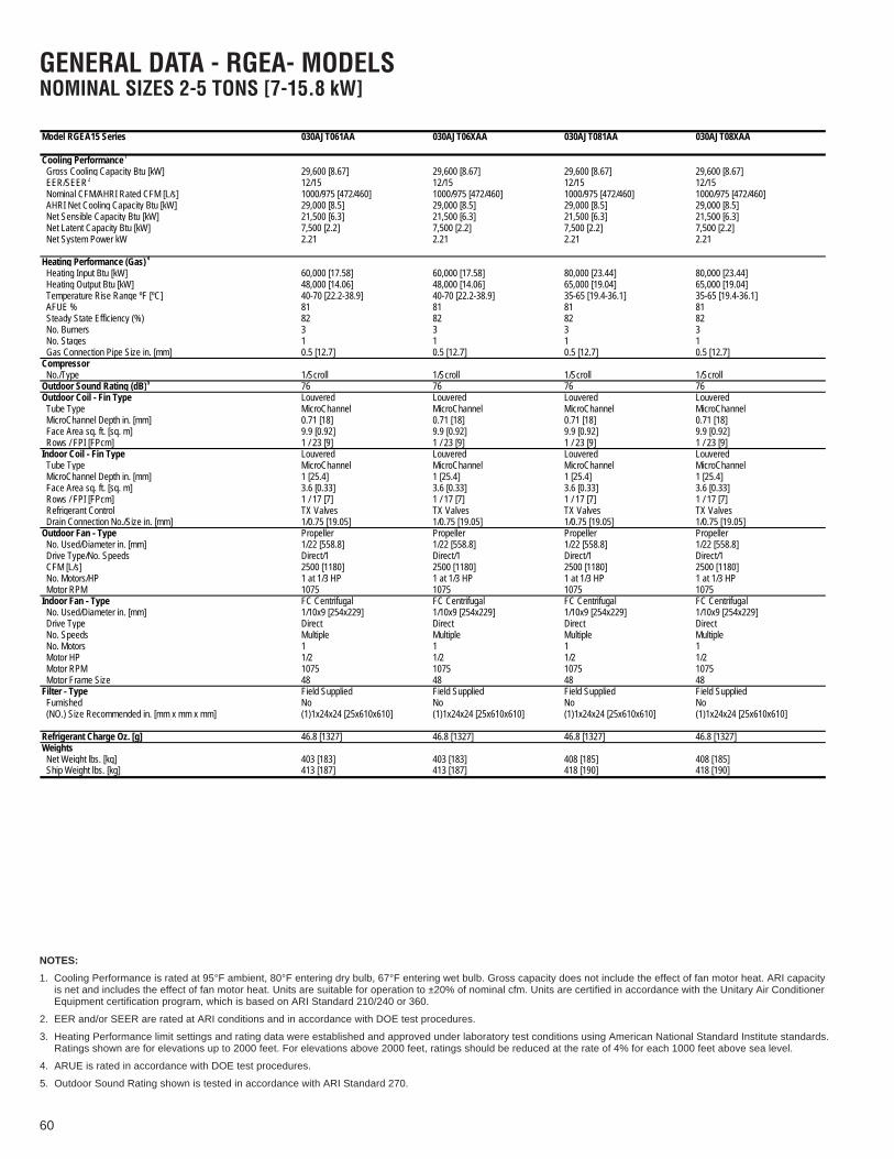
60
GENERAL DATA - RGEA- MODELSNOMINAL SIZES 2-5 TONS [7-15.8 kW]
Model RGEA15 Series 030AJT061AA 030AJT06XAA 030AJT081AA 030AJT08XAA
Cooling Performance1 Continued -> Gross Cooling Capacity Btu [kW] 29,600 [8.67] 29,600 [8.67] 29,600 [8.67] 29,600 [8.67] EER/SEER2 12/15 12/15 12/15 12/15 Nominal CFM/AHRI Rated CFM [L/s] 1000/975 [472/460] 1000/975 [472/460] 1000/975 [472/460] 1000/975 [472/460] AHRI Net Cooling Capacity Btu [kW] 29,000 [8.5] 29,000 [8.5] 29,000 [8.5] 29,000 [8.5] Net Sensible Capacity Btu [kW] 21,500 [6.3] 21,500 [6.3] 21,500 [6.3] 21,500 [6.3] Net Latent Capacity Btu [kW] 7,500 [2.2] 7,500 [2.2] 7,500 [2.2] 7,500 [2.2] Net System Power kW 2.21 2.21 2.21 2.21
Heating Performance (Gas) 4
Heating Input Btu [kW] 60,000 [17.58] 60,000 [17.58] 80,000 [23.44] 80,000 [23.44] Heating Output Btu [kW] 48,000 [14.06] 48,000 [14.06] 65,000 [19.04] 65,000 [19.04] Temperature Rise Range ºF [ºC] 40-70 [22.2-38.9] 40-70 [22.2-38.9] 35-65 [19.4-36.1] 35-65 [19.4-36.1] AFUE % 81 81 81 81 Steady State Efficiency (%) 82 82 82 82 No. Burners 3 3 3 3 No. Stages 1 1 1 1 Gas Connection Pipe Size in. [mm] 0.5 [12.7] 0.5 [12.7] 0.5 [12.7] 0.5 [12.7]Compressor No./Type 1/Scroll 1/Scroll 1/Scroll 1/ScrollOutdoor Sound Rating (dB)5 76 76 76 76Outdoor Coil - Fin Type Louvered Louvered Louvered Louvered Tube Type MicroChannel MicroChannel MicroChannel MicroChannel MicroChannel Depth in. [mm] 0.71 [18] 0.71 [18] 0.71 [18] 0.71 [18] Face Area sq. ft. [sq. m] 9.9 [0.92] 9.9 [0.92] 9.9 [0.92] 9.9 [0.92] Rows / FPI [FPcm] 1 / 23 [9] 1 / 23 [9] 1 / 23 [9] 1 / 23 [9]Indoor Coil - Fin Type Louvered Louvered Louvered Louvered Tube Type MicroChannel MicroChannel MicroChannel MicroChannel MicroChannel Depth in. [mm] 1 [25.4] 1 [25.4] 1 [25.4] 1 [25.4] Face Area sq. ft. [sq. m] 3.6 [0.33] 3.6 [0.33] 3.6 [0.33] 3.6 [0.33] Rows / FPI [FPcm] 1 / 17 [7] 1 / 17 [7] 1 / 17 [7] 1 / 17 [7] Refrigerant Control TX Valves TX Valves TX Valves TX Valves Drain Connection No./Size in. [mm] 1/0.75 [19.05] 1/0.75 [19.05] 1/0.75 [19.05] 1/0.75 [19.05]Outdoor Fan - Type Propeller Propeller Propeller Propeller No. Used/Diameter in. [mm] 1/22 [558.8] 1/22 [558.8] 1/22 [558.8] 1/22 [558.8] Drive Type/No. Speeds Direct/1 Direct/1 Direct/1 Direct/1 CFM [L/s] 2500 [1180] 2500 [1180] 2500 [1180] 2500 [1180] No. Motors/HP 1 at 1/3 HP 1 at 1/3 HP 1 at 1/3 HP 1 at 1/3 HP Motor RPM 1075 1075 1075 1075Indoor Fan - Type FC Centrifugal FC Centrifugal FC Centrifugal FC Centrifugal No. Used/Diameter in. [mm] 1/10x9 [254x229] 1/10x9 [254x229] 1/10x9 [254x229] 1/10x9 [254x229] Drive Type Direct Direct Direct Direct No. Speeds Multiple Multiple Multiple Multiple No. Motors 1 1 1 1 Motor HP 1/2 1/2 1/2 1/2 Motor RPM 1075 1075 1075 1075 Motor Frame Size 48 48 48 48Filter - Type Field Supplied Field Supplied Field Supplied Field Supplied Furnished No No No No (NO.) Size Recommended in. [mm x mm x mm] (1)1x24x24 [25x610x610] (1)1x24x24 [25x610x610] (1)1x24x24 [25x610x610] (1)1x24x24 [25x610x610]
Refrigerant Charge Oz. [g] 46.8 [1327] 46.8 [1327] 46.8 [1327] 46.8 [1327]Weights Net Weight lbs. [kg] 403 [183] 403 [183] 408 [185] 408 [185] Ship Weight lbs. [kg] 413 [187] 413 [187] 418 [190] 418 [190]
NOTES:
1. Cooling Performance is rated at 95°F ambient, 80°F entering dry bulb, 67°F entering wet bulb. Gross capacity does not include the effect of fan motor heat. ARI capacityis net and includes the effect of fan motor heat. Units are suitable for operation to ±20% of nominal cfm. Units are certified in accordance with the Unitary Air ConditionerEquipment certification program, which is based on ARI Standard 210/240 or 360.
2. EER and/or SEER are rated at ARI conditions and in accordance with DOE test procedures.
3. Heating Performance limit settings and rating data were established and approved under laboratory test conditions using American National Standard Institute standards.Ratings shown are for elevations up to 2000 feet. For elevations above 2000 feet, ratings should be reduced at the rate of 4% for each 1000 feet above sea level.
4. ARUE is rated in accordance with DOE test procedures.
5. Outdoor Sound Rating shown is tested in accordance with ARI Standard 270.

61
GENERAL DATA - RGEA- MODELSNOMINAL SIZES 2-5 TONS [7-15.8 kW]
Model RGEA15 Series 030AJV061AA 030AJV06XAA 030AJV081AA 030AJV08XAA
Cooling Performance1 Continued -> Gross Cooling Capacity Btu [kW] 29,600 [8.67] 29,600 [8.67] 29,600 [8.67] 29,600 [8.67] EER/SEER2 12/15 12/15 12/15 12/15 Nominal CFM/AHRI Rated CFM [L/s] 1000/975 [472/460] 1000/975 [472/460] 1000/975 [472/460] 1000/975 [472/460] AHRI Net Cooling Capacity Btu [kW] 29,000 [8.5] 29,000 [8.5] 29,000 [8.5] 29,000 [8.5] Net Sensible Capacity Btu [kW] 21,500 [6.3] 21,500 [6.3] 21,500 [6.3] 21,500 [6.3] Net Latent Capacity Btu [kW] 7,500 [2.2] 7,500 [2.2] 7,500 [2.2] 7,500 [2.2] Net System Power kW 2.21 2.21 2.21 2.21
Heating Performance (Gas) 4
Heating Input Btu [kW] 60,000 [17.58] 60,000 [17.58] 80,000 [23.44] 80,000 [23.44] Heating Output Btu [kW] 48,000 [14.06] 48,000 [14.06] 65,000 [19.04] 65,000 [19.04] Temperature Rise Range ºF [ºC] 40-70 [22.2-38.9] 40-70 [22.2-38.9] 35-65 [19.4-36.1] 35-65 [19.4-36.1] AFUE % 81 81 81 81 Steady State Efficiency (%) 82 82 82 82 No. Burners 3 3 3 3 No. Stages 1 1 1 1 Gas Connection Pipe Size in. [mm] 0.5 [12.7] 0.5 [12.7] 0.5 [12.7] 0.5 [12.7]Compressor No./Type 1/Scroll 1/Scroll 1/Scroll 1/ScrollOutdoor Sound Rating (dB)5 76 76 76 76Outdoor Coil - Fin Type Louvered Louvered Louvered Louvered Tube Type MicroChannel MicroChannel MicroChannel MicroChannel MicroChannel Depth in. [mm] 0.71 [18] 0.71 [18] 0.71 [18] 0.71 [18] Face Area sq. ft. [sq. m] 9.9 [0.92] 9.9 [0.92] 9.9 [0.92] 9.9 [0.92] Rows / FPI [FPcm] 1 / 23 [9] 1 / 23 [9] 1 / 23 [9] 1 / 23 [9]Indoor Coil - Fin Type Louvered Louvered Louvered Louvered Tube Type MicroChannel MicroChannel MicroChannel MicroChannel MicroChannel Depth in. [mm] 1 [25.4] 1 [25.4] 1 [25.4] 1 [25.4] Face Area sq. ft. [sq. m] 3.6 [0.33] 3.6 [0.33] 3.6 [0.33] 3.6 [0.33] Rows / FPI [FPcm] 1 / 17 [7] 1 / 17 [7] 1 / 17 [7] 1 / 17 [7] Refrigerant Control TX Valves TX Valves TX Valves TX Valves Drain Connection No./Size in. [mm] 1/0.75 [19.05] 1/0.75 [19.05] 1/0.75 [19.05] 1/0.75 [19.05]Outdoor Fan - Type Propeller Propeller Propeller Propeller No. Used/Diameter in. [mm] 1/22 [558.8] 1/22 [558.8] 1/22 [558.8] 1/22 [558.8] Drive Type/No. Speeds Direct/1 Direct/1 Direct/1 Direct/1 CFM [L/s] 2500 [1180] 2500 [1180] 2500 [1180] 2500 [1180] No. Motors/HP 1 at 1/3 HP 1 at 1/3 HP 1 at 1/3 HP 1 at 1/3 HP Motor RPM 1075 1075 1075 1075Indoor Fan - Type FC Centrifugal FC Centrifugal FC Centrifugal FC Centrifugal No. Used/Diameter in. [mm] 1/10x9 [254x229] 1/10x9 [254x229] 1/10x9 [254x229] 1/10x9 [254x229] Drive Type Direct Direct Direct Direct No. Speeds Multiple Multiple Multiple Multiple No. Motors 1 1 1 1 Motor HP 1/2 1/2 1/2 1/2 Motor RPM 1050 1050 1050 1050 Motor Frame Size 48 48 48 48Filter - Type Field Supplied Field Supplied Field Supplied Field Supplied Furnished No No No No (NO.) Size Recommended in. [mm x mm x mm] (1)1x24x24 [25x610x610] (1)1x24x24 [25x610x610] (1)1x24x24 [25x610x610] (1)1x24x24 [25x610x610]
Refrigerant Charge Oz. [g] 46.8 [1327] 46.8 [1327] 46.8 [1327] 46.8 [1327]Weights Net Weight lbs. [kg] 403 [183] 403 [183] 408 [185] 408 [185] Ship Weight lbs. [kg] 413 [187] 413 [187] 418 [190] 418 [190]
NOTES:
1. Cooling Performance is rated at 95°F ambient, 80°F entering dry bulb, 67°F entering wet bulb. Gross capacity does not include the effect of fan motor heat. ARI capacityis net and includes the effect of fan motor heat. Units are suitable for operation to ±20% of nominal cfm. Units are certified in accordance with the Unitary Air ConditionerEquipment certification program, which is based on ARI Standard 210/240 or 360.
2. EER and/or SEER are rated at ARI conditions and in accordance with DOE test procedures.
3. Heating Performance limit settings and rating data were established and approved under laboratory test conditions using American National Standard Institute standards.Ratings shown are for elevations up to 2000 feet. For elevations above 2000 feet, ratings should be reduced at the rate of 4% for each 1000 feet above sea level.
4. ARUE is rated in accordance with DOE test procedures.
5. Outdoor Sound Rating shown is tested in accordance with ARI Standard 270.

62
GENERAL DATA - RGEA- MODELSNOMINAL SIZES 2-5 TONS [7-15.8 kW]
Model RGEA15 Series 036ACT061AA 036ACT081AA 036ACT101AA 036ADT061AA
Cooling Performance1 Continued -> Gross Cooling Capacity Btu [kW] 36,000 [10.55] 36,000 [10.55] 36,000 [10.55] 36,000 [10.55] EER/SEER2 12/15 12/15 12/15 12/15 Nominal CFM/AHRI Rated CFM [L/s] 1200/1200 [566/566] 1200/1200 [566/566] 1200/1200 [566/566] 1200/1200 [566/566] AHRI Net Cooling Capacity Btu [kW] 35,000 [10.25] 35,000 [10.25] 35,000 [10.25] 35,000 [10.25] Net Sensible Capacity Btu [kW] 25,400 [7.44] 25,400 [7.44] 25,400 [7.44] 25,400 [7.44] Net Latent Capacity Btu [kW] 9,600 [2.81] 9,600 [2.81] 9,600 [2.81] 9,600 [2.81] Net System Power kW 2.77 2.77 2.77 2.77
Heating Performance (Gas) 4
Heating Input Btu [kW] 60,000 [17.58] 80,000 [23.44] 100,000 [29.3] 60,000 [17.58] Heating Output Btu [kW] 48,000 [14.06] 65,000 [19.04] 81,000 [23.73] 48,000 [14.06] Temperature Rise Range ºF [ºC] 40-70 [22.2-38.9] 35-65 [19.4-36.1] 45-75 [25-41.7] 40-70 [22.2-38.9] AFUE % 81 81 81 81 Steady State Efficiency (%) 82 82 82 82 No. Burners 3 3 3 3 No. Stages 1 1 1 1 Gas Connection Pipe Size in. [mm] 0.5 [12.7] 0.5 [12.7] 0.5 [12.7] 0.5 [12.7]Compressor No./Type 1/Scroll 1/Scroll 1/Scroll 1/ScrollOutdoor Sound Rating (dB)5 76 76 76 76Outdoor Coil - Fin Type Louvered Louvered Louvered Louvered Tube Type MicroChannel MicroChannel MicroChannel MicroChannel MicroChannel Depth in. [mm] 0.71 [18] 0.71 [18] 0.71 [18] 0.71 [18] Face Area sq. ft. [sq. m] 9.8 [0.91] 9.8 [0.91] 9.8 [0.91] 9.8 [0.91] Rows / FPI [FPcm] 1 / 23 [9] 1 / 23 [9] 1 / 23 [9] 1 / 23 [9]Indoor Coil - Fin Type Louvered Louvered Louvered Louvered Tube Type MicroChannel MicroChannel MicroChannel MicroChannel MicroChannel Depth in. [mm] 1 [25.4] 1 [25.4] 1 [25.4] 1 [25.4] Face Area sq. ft. [sq. m] 3.6 [0.33] 3.6 [0.33] 3.6 [0.33] 3.6 [0.33] Rows / FPI [FPcm] 1 / 17 [7] 1 / 17 [7] 1 / 17 [7] 1 / 17 [7] Refrigerant Control TX Valves TX Valves TX Valves TX Valves Drain Connection No./Size in. [mm] 1/0.75 [19.05] 1/0.75 [19.05] 1/0.75 [19.05] 1/0.75 [19.05]Outdoor Fan - Type Propeller Propeller Propeller Propeller No. Used/Diameter in. [mm] 1/22 [558.8] 1/22 [558.8] 1/22 [558.8] 1/22 [558.8] Drive Type/No. Speeds Direct/1 Direct/1 Direct/1 Direct/1 CFM [L/s] 2700 [1274] 2700 [1274] 2700 [1274] 2700 [1274] No. Motors/HP 1 at 1/3 HP 1 at 1/3 HP 1 at 1/3 HP 1 at 1/3 HP Motor RPM 1075 1075 1075 1075Indoor Fan - Type FC Centrifugal FC Centrifugal FC Centrifugal FC Centrifugal No. Used/Diameter in. [mm] 1/12x9 [305x229] 1/12x9 [305x229] 1/12x9 [305x229] 1/12x9 [305x229] Drive Type Direct Direct Direct Direct No. Speeds Multiple Multiple Multiple Multiple No. Motors 1 1 1 1 Motor HP 1/2 1/2 1/2 1/2 Motor RPM 1075 1075 1075 1075 Motor Frame Size 48 48 48 48Filter - Type Field Supplied Field Supplied Field Supplied Field Supplied Furnished No No No No (NO.) Size Recommended in. [mm x mm x mm] (1)1x24x24 [25x610x610] (1)1x24x24 [25x610x610] (1)1x24x24 [25x610x610] (1)1x24x24 [25x610x610]
Refrigerant Charge Oz. [g] 52.7 [1494] 52.7 [1494] 52.7 [1494] 52.7 [1494]Weights Net Weight lbs. [kg] 411 [186] 416 [189] 421 [191] 411 [186] Ship Weight lbs. [kg] 421 [191] 426 [193] 431 [196] 421 [191]
NOTES:
1. Cooling Performance is rated at 95°F ambient, 80°F entering dry bulb, 67°F entering wet bulb. Gross capacity does not include the effect of fan motor heat. ARI capacityis net and includes the effect of fan motor heat. Units are suitable for operation to ±20% of nominal cfm. Units are certified in accordance with the Unitary Air ConditionerEquipment certification program, which is based on ARI Standard 210/240 or 360.
2. EER and/or SEER are rated at ARI conditions and in accordance with DOE test procedures.
3. Heating Performance limit settings and rating data were established and approved under laboratory test conditions using American National Standard Institute standards.Ratings shown are for elevations up to 2000 feet. For elevations above 2000 feet, ratings should be reduced at the rate of 4% for each 1000 feet above sea level.
4. ARUE is rated in accordance with DOE test procedures.
5. Outdoor Sound Rating shown is tested in accordance with ARI Standard 270.

63
GENERAL DATA - RGEA- MODELSNOMINAL SIZES 2-5 TONS [7-15.8 kW]
Model RGEA15 Series 036ADT081AA 036ADT101AA 036AJT061AA 036AJT06XAA
Cooling Performance1 Continued -> Gross Cooling Capacity Btu [kW] 36,000 [10.55] 36,000 [10.55] 36,000 [10.55] 36,000 [10.55] EER/SEER2 12/15 12/15 12/15 12/15 Nominal CFM/AHRI Rated CFM [L/s] 1200/1200 [566/566] 1200/1200 [566/566] 1200/1200 [566/566] 1200/1200 [566/566] AHRI Net Cooling Capacity Btu [kW] 35,000 [10.25] 35,000 [10.25] 35,000 [10.25] 35,000 [10.25] Net Sensible Capacity Btu [kW] 25,400 [7.44] 25,400 [7.44] 25,400 [7.44] 25,400 [7.44] Net Latent Capacity Btu [kW] 9,600 [2.81] 9,600 [2.81] 9,600 [2.81] 9,600 [2.81] Net System Power kW 2.77 2.77 2.77 2.77
Heating Performance (Gas) 4
Heating Input Btu [kW] 80,000 [23.44] 100,000 [29.3] 60,000 [17.58] 60,000 [17.58] Heating Output Btu [kW] 65,000 [19.04] 81,000 [23.73] 48,000 [14.06] 48,000 [14.06] Temperature Rise Range ºF [ºC] 35-65 [19.4-36.1] 45-75 [25-41.7] 40-70 [22.2-38.9] 40-70 [22.2-38.9] AFUE % 81 81 81 81 Steady State Efficiency (%) 82 82 82 82 No. Burners 3 3 3 3 No. Stages 1 1 1 1 Gas Connection Pipe Size in. [mm] 0.5 [12.7] 0.5 [12.7] 0.5 [12.7] 0.5 [12.7]Compressor No./Type 1/Scroll 1/Scroll 1/Scroll 1/ScrollOutdoor Sound Rating (dB)5 76 76 76 76Outdoor Coil - Fin Type Louvered Louvered Louvered Louvered Tube Type MicroChannel MicroChannel MicroChannel MicroChannel MicroChannel Depth in. [mm] 0.71 [18] 0.71 [18] 0.71 [18] 0.71 [18] Face Area sq. ft. [sq. m] 9.8 [0.91] 9.8 [0.91] 9.8 [0.91] 9.8 [0.91] Rows / FPI [FPcm] 1 / 23 [9] 1 / 23 [9] 1 / 23 [9] 1 / 23 [9]Indoor Coil - Fin Type Louvered Louvered Louvered Louvered Tube Type MicroChannel MicroChannel MicroChannel MicroChannel MicroChannel Depth in. [mm] 1 [25.4] 1 [25.4] 1 [25.4] 1 [25.4] Face Area sq. ft. [sq. m] 3.6 [0.33] 3.6 [0.33] 3.6 [0.33] 3.6 [0.33] Rows / FPI [FPcm] 1 / 17 [7] 1 / 17 [7] 1 / 17 [7] 1 / 17 [7] Refrigerant Control TX Valves TX Valves TX Valves TX Valves Drain Connection No./Size in. [mm] 1/0.75 [19.05] 1/0.75 [19.05] 1/0.75 [19.05] 1/0.75 [19.05]Outdoor Fan - Type Propeller Propeller Propeller Propeller No. Used/Diameter in. [mm] 1/22 [558.8] 1/22 [558.8] 1/22 [558.8] 1/22 [558.8] Drive Type/No. Speeds Direct/1 Direct/1 Direct/1 Direct/1 CFM [L/s] 2700 [1274] 2700 [1274] 2700 [1274] 2700 [1274] No. Motors/HP 1 at 1/3 HP 1 at 1/3 HP 1 at 1/3 HP 1 at 1/3 HP Motor RPM 1075 1075 1075 1075Indoor Fan - Type FC Centrifugal FC Centrifugal FC Centrifugal FC Centrifugal No. Used/Diameter in. [mm] 1/12x9 [305x229] 1/12x9 [305x229] 1/12x9 [305x229] 1/12x9 [305x229] Drive Type Direct Direct Direct Direct No. Speeds Multiple Multiple Multiple Multiple No. Motors 1 1 1 1 Motor HP 1/2 1/2 1/2 1/2 Motor RPM 1075 1075 1075 1075 Motor Frame Size 48 48 48 48Filter - Type Field Supplied Field Supplied Field Supplied Field Supplied Furnished No No No No (NO.) Size Recommended in. [mm x mm x mm] (1)1x24x24 [25x610x610] (1)1x24x24 [25x610x610] (1)1x24x24 [25x610x610] (1)1x24x24 [25x610x610]
Refrigerant Charge Oz. [g] 52.7 [1494] 52.7 [1494] 52.7 [1494] 52.7 [1494]Weights Net Weight lbs. [kg] 416 [189] 421 [191] 411 [186] 411 [186] Ship Weight lbs. [kg] 426 [193] 431 [196] 421 [191] 421 [191]
NOTES:
1. Cooling Performance is rated at 95°F ambient, 80°F entering dry bulb, 67°F entering wet bulb. Gross capacity does not include the effect of fan motor heat. ARI capacityis net and includes the effect of fan motor heat. Units are suitable for operation to ±20% of nominal cfm. Units are certified in accordance with the Unitary Air ConditionerEquipment certification program, which is based on ARI Standard 210/240 or 360.
2. EER and/or SEER are rated at ARI conditions and in accordance with DOE test procedures.
3. Heating Performance limit settings and rating data were established and approved under laboratory test conditions using American National Standard Institute standards.Ratings shown are for elevations up to 2000 feet. For elevations above 2000 feet, ratings should be reduced at the rate of 4% for each 1000 feet above sea level.
4. ARUE is rated in accordance with DOE test procedures.
5. Outdoor Sound Rating shown is tested in accordance with ARI Standard 270.

64
GENERAL DATA - RGEA- MODELSNOMINAL SIZES 2-5 TONS [7-15.8 kW]
Model RGEA15 Series 036AJT081AA 036AJT08XAA 036AJT101AA 036AJT10XAA
Cooling Performance1 Continued -> Gross Cooling Capacity Btu [kW] 36,000 [10.55] 36,000 [10.55] 36,000 [10.55] 36,000 [10.55] EER/SEER2 12/15 12/15 12/15 12/15 Nominal CFM/AHRI Rated CFM [L/s] 1200/1200 [566/566] 1200/1200 [566/566] 1200/1200 [566/566] 1200/1200 [566/566] AHRI Net Cooling Capacity Btu [kW] 35,000 [10.25] 35,000 [10.25] 35,000 [10.25] 35,000 [10.25] Net Sensible Capacity Btu [kW] 25,400 [7.44] 25,400 [7.44] 25,400 [7.44] 25,400 [7.44] Net Latent Capacity Btu [kW] 9,600 [2.81] 9,600 [2.81] 9,600 [2.81] 9,600 [2.81] Net System Power kW 2.77 2.77 2.77 2.77
Heating Performance (Gas) 4
Heating Input Btu [kW] 80,000 [23.44] 80,000 [23.44] 100,000 [29.3] 100,000 [29.3] Heating Output Btu [kW] 65,000 [19.04] 65,000 [19.04] 81,000 [23.73] 81,000 [23.73] Temperature Rise Range ºF [ºC] 35-65 [19.4-36.1] 35-65 [19.4-36.1] 45-75 [25-41.7] 45-75 [25-41.7] AFUE % 81 81 81 81 Steady State Efficiency (%) 82 82 82 82 No. Burners 3 3 3 3 No. Stages 1 1 1 1 Gas Connection Pipe Size in. [mm] 0.5 [12.7] 0.5 [12.7] 0.5 [12.7] 0.5 [12.7]Compressor No./Type 1/Scroll 1/Scroll 1/Scroll 1/ScrollOutdoor Sound Rating (dB)5 76 76 76 76Outdoor Coil - Fin Type Louvered Louvered Louvered Louvered Tube Type MicroChannel MicroChannel MicroChannel MicroChannel MicroChannel Depth in. [mm] 0.71 [18] 0.71 [18] 0.71 [18] 0.71 [18] Face Area sq. ft. [sq. m] 9.8 [0.91] 9.8 [0.91] 9.8 [0.91] 9.8 [0.91] Rows / FPI [FPcm] 1 / 23 [9] 1 / 23 [9] 1 / 23 [9] 1 / 23 [9]Indoor Coil - Fin Type Louvered Louvered Louvered Louvered Tube Type MicroChannel MicroChannel MicroChannel MicroChannel MicroChannel Depth in. [mm] 1 [25.4] 1 [25.4] 1 [25.4] 1 [25.4] Face Area sq. ft. [sq. m] 3.6 [0.33] 3.6 [0.33] 3.6 [0.33] 3.6 [0.33] Rows / FPI [FPcm] 1 / 17 [7] 1 / 17 [7] 1 / 17 [7] 1 / 17 [7] Refrigerant Control TX Valves TX Valves TX Valves TX Valves Drain Connection No./Size in. [mm] 1/0.75 [19.05] 1/0.75 [19.05] 1/0.75 [19.05] 1/0.75 [19.05]Outdoor Fan - Type Propeller Propeller Propeller Propeller No. Used/Diameter in. [mm] 1/22 [558.8] 1/22 [558.8] 1/22 [558.8] 1/22 [558.8] Drive Type/No. Speeds Direct/1 Direct/1 Direct/1 Direct/1 CFM [L/s] 2700 [1274] 2700 [1274] 2700 [1274] 2700 [1274] No. Motors/HP 1 at 1/3 HP 1 at 1/3 HP 1 at 1/3 HP 1 at 1/3 HP Motor RPM 1075 1075 1075 1075Indoor Fan - Type FC Centrifugal FC Centrifugal FC Centrifugal FC Centrifugal No. Used/Diameter in. [mm] 1/12x9 [305x229] 1/12x9 [305x229] 1/12x9 [305x229] 1/12x9 [305x229] Drive Type Direct Direct Direct Direct No. Speeds Multiple Multiple Multiple Multiple No. Motors 1 1 1 1 Motor HP 1/2 1/2 1/2 1/2 Motor RPM 1075 1075 1075 1075 Motor Frame Size 48 48 48 48Filter - Type Field Supplied Field Supplied Field Supplied Field Supplied Furnished No No No No (NO.) Size Recommended in. [mm x mm x mm] (1)1x24x24 [25x610x610] (1)1x24x24 [25x610x610] (1)1x24x24 [25x610x610] (1)1x24x24 [25x610x610]
Refrigerant Charge Oz. [g] 52.7 [1494] 52.7 [1494] 52.7 [1494] 52.7 [1494]Weights Net Weight lbs. [kg] 416 [189] 416 [189] 421 [191] 421 [191] Ship Weight lbs. [kg] 426 [193] 426 [193] 431 [196] 431 [196]
NOTES:
1. Cooling Performance is rated at 95°F ambient, 80°F entering dry bulb, 67°F entering wet bulb. Gross capacity does not include the effect of fan motor heat. ARI capacityis net and includes the effect of fan motor heat. Units are suitable for operation to ±20% of nominal cfm. Units are certified in accordance with the Unitary Air ConditionerEquipment certification program, which is based on ARI Standard 210/240 or 360.
2. EER and/or SEER are rated at ARI conditions and in accordance with DOE test procedures.
3. Heating Performance limit settings and rating data were established and approved under laboratory test conditions using American National Standard Institute standards.Ratings shown are for elevations up to 2000 feet. For elevations above 2000 feet, ratings should be reduced at the rate of 4% for each 1000 feet above sea level.
4. ARUE is rated in accordance with DOE test procedures.
5. Outdoor Sound Rating shown is tested in accordance with ARI Standard 270.
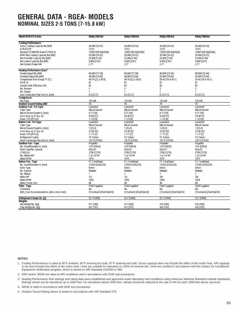
65
GENERAL DATA - RGEA- MODELSNOMINAL SIZES 2-5 TONS [7-15.8 kW]
Model RGEA15 Series 036AJV061AA 036AJV06XAA 036AJV081AA 036AJV08XAA
Cooling Performance1 Continued -> Gross Cooling Capacity Btu [kW] 36,000 [10.55] 36,000 [10.55] 36,000 [10.55] 36,000 [10.55] EER/SEER2 12/15 12/15 12/15 12/15 Nominal CFM/AHRI Rated CFM [L/s] 1200/1200 [566/566] 1200/1200 [566/566] 1200/1200 [566/566] 1200/1200 [566/566] AHRI Net Cooling Capacity Btu [kW] 35,000 [10.25] 35,000 [10.25] 35,000 [10.25] 35,000 [10.25] Net Sensible Capacity Btu [kW] 25,400 [7.44] 25,400 [7.44] 25,400 [7.44] 25,400 [7.44] Net Latent Capacity Btu [kW] 9,600 [2.81] 9,600 [2.81] 9,600 [2.81] 9,600 [2.81] Net System Power kW 2.77 2.77 2.77 2.77
Heating Performance (Gas) 4
Heating Input Btu [kW] 60,000 [17.58] 60,000 [17.58] 80,000 [23.44] 80,000 [23.44] Heating Output Btu [kW] 48,000 [14.06] 48,000 [14.06] 65,000 [19.04] 65,000 [19.04] Temperature Rise Range ºF [ºC] 40-70 [22.2-38.9] 40-70 [22.2-38.9] 35-65 [19.4-36.1] 35-65 [19.4-36.1] AFUE % 81 81 81 81 Steady State Efficiency (%) 82 82 82 82 No. Burners 3 3 3 3 No. Stages 1 1 1 1 Gas Connection Pipe Size in. [mm] 0.5 [12.7] 0.5 [12.7] 0.5 [12.7] 0.5 [12.7]Compressor No./Type 1/Scroll 1/Scroll 1/Scroll 1/ScrollOutdoor Sound Rating (dB)5 76 76 76 76Outdoor Coil - Fin Type Louvered Louvered Louvered Louvered Tube Type MicroChannel MicroChannel MicroChannel MicroChannel MicroChannel Depth in. [mm] 0.71 [18] 0.71 [18] 0.71 [18] 0.71 [18] Face Area sq. ft. [sq. m] 9.8 [0.91] 9.8 [0.91] 9.8 [0.91] 9.8 [0.91] Rows / FPI [FPcm] 1 / 23 [9] 1 / 23 [9] 1 / 23 [9] 1 / 23 [9]Indoor Coil - Fin Type Louvered Louvered Louvered Louvered Tube Type MicroChannel MicroChannel MicroChannel MicroChannel MicroChannel Depth in. [mm] 1 [25.4] 1 [25.4] 1 [25.4] 1 [25.4] Face Area sq. ft. [sq. m] 3.6 [0.33] 3.6 [0.33] 3.6 [0.33] 3.6 [0.33] Rows / FPI [FPcm] 1 / 17 [7] 1 / 17 [7] 1 / 17 [7] 1 / 17 [7] Refrigerant Control TX Valves TX Valves TX Valves TX Valves Drain Connection No./Size in. [mm] 1/0.75 [19.05] 1/0.75 [19.05] 1/0.75 [19.05] 1/0.75 [19.05]Outdoor Fan - Type Propeller Propeller Propeller Propeller No. Used/Diameter in. [mm] 1/22 [558.8] 1/22 [558.8] 1/22 [558.8] 1/22 [558.8] Drive Type/No. Speeds Direct/1 Direct/1 Direct/1 Direct/1 CFM [L/s] 2700 [1274] 2700 [1274] 2700 [1274] 2700 [1274] No. Motors/HP 1 at 1/3 HP 1 at 1/3 HP 1 at 1/3 HP 1 at 1/3 HP Motor RPM 1075 1075 1075 1075Indoor Fan - Type FC Centrifugal FC Centrifugal FC Centrifugal FC Centrifugal No. Used/Diameter in. [mm] 1/10x9 [254x229] 1/10x9 [254x229] 1/10x9 [254x229] 1/10x9 [254x229] Drive Type Direct Direct Direct Direct No. Speeds Multiple Multiple Multiple Multiple No. Motors 1 1 1 1 Motor HP 1/2 1/2 3/4 3/4 Motor RPM 1050 1050 1050 1050 Motor Frame Size 48 48 48 48Filter - Type Field Supplied Field Supplied Field Supplied Field Supplied Furnished No No No No (NO.) Size Recommended in. [mm x mm x mm] (1)1x24x24 [25x610x610] (1)1x24x24 [25x610x610] (1)1x24x24 [25x610x610] (1)1x24x24 [25x610x610]
Refrigerant Charge Oz. [g] 52.7 [1494] 52.7 [1494] 52.7 [1494] 52.7 [1494]Weights Net Weight lbs. [kg] 411 [186] 411 [186] 416 [189] 416 [189] Ship Weight lbs. [kg] 421 [191] 421 [191] 426 [193] 426 [193]
NOTES:
1. Cooling Performance is rated at 95°F ambient, 80°F entering dry bulb, 67°F entering wet bulb. Gross capacity does not include the effect of fan motor heat. ARI capacityis net and includes the effect of fan motor heat. Units are suitable for operation to ±20% of nominal cfm. Units are certified in accordance with the Unitary Air ConditionerEquipment certification program, which is based on ARI Standard 210/240 or 360.
2. EER and/or SEER are rated at ARI conditions and in accordance with DOE test procedures.
3. Heating Performance limit settings and rating data were established and approved under laboratory test conditions using American National Standard Institute standards.Ratings shown are for elevations up to 2000 feet. For elevations above 2000 feet, ratings should be reduced at the rate of 4% for each 1000 feet above sea level.
4. ARUE is rated in accordance with DOE test procedures.
5. Outdoor Sound Rating shown is tested in accordance with ARI Standard 270.

66
GENERAL DATA - RGEA- MODELSNOMINAL SIZES 2-5 TONS [7-15.8 kW]
Model RGEA15 Series 036AJV101AA 036AJV10XAA 042ACT081AA 042ACT101AA
Cooling Performance1 Continued -> Gross Cooling Capacity Btu [kW] 36,000 [10.55] 36,000 [10.55] 41,000 [12.01] 41,000 [12.01] EER/SEER2 12/15 12/15 12/15 12/15 Nominal CFM/AHRI Rated CFM [L/s] 1200/1200 [566/566] 1200/1200 [566/566] 1400/1300 [661/613] 1400/1300 [661/613] AHRI Net Cooling Capacity Btu [kW] 35,000 [10.25] 35,000 [10.25] 40,000 [11.72] 40,000 [11.72] Net Sensible Capacity Btu [kW] 25,400 [7.44] 25,400 [7.44] 28,600 [8.38] 28,600 [8.38] Net Latent Capacity Btu [kW] 9,600 [2.81] 9,600 [2.81] 11,400 [3.34] 11,400 [3.34] Net System Power kW 2.77 2.77 3.28 3.28
Heating Performance (Gas) 4
Heating Input Btu [kW] 100,000 [29.3] 100,000 [29.3] 80,000 [23.44] 100,000 [29.3] Heating Output Btu [kW] 81,000 [23.73] 81,000 [23.73] 65,000 [19.04] 81,000 [23.73] Temperature Rise Range ºF [ºC] 45-75 [25-41.7] 45-75 [25-41.7] 35-65 [19.4-36.1] 45-75 [25-41.7] AFUE % 81 81 81 81 Steady State Efficiency (%) 82 82 82 82 No. Burners 3 3 4 4 No. Stages 1 1 1 1 Gas Connection Pipe Size in. [mm] 0.5 [12.7] 0.5 [12.7] 0.5 [12.7] 0.5 [12.7]Compressor No./Type 1/Scroll 1/Scroll 1/Scroll 1/ScrollOutdoor Sound Rating (dB)5 76 76 76 76Outdoor Coil - Fin Type Louvered Louvered Louvered Louvered Tube Type MicroChannel MicroChannel MicroChannel MicroChannel MicroChannel Depth in. [mm] 0.71 [18] 0.71 [18] 0.71 [18] 0.71 [18] Face Area sq. ft. [sq. m] 9.8 [0.91] 9.8 [0.91] 14.1 [1.31] 14.1 [1.31] Rows / FPI [FPcm] 1 / 23 [9] 1 / 23 [9] 1 / 23 [9] 1 / 23 [9]Indoor Coil - Fin Type Louvered Louvered Louvered Louvered Tube Type MicroChannel MicroChannel MicroChannel MicroChannel MicroChannel Depth in. [mm] 1 [25.4] 1 [25.4] 1 [25.4] 1 [25.4] Face Area sq. ft. [sq. m] 3.6 [0.33] 3.6 [0.33] 3.6 [0.33] 3.6 [0.33] Rows / FPI [FPcm] 1 / 17 [7] 1 / 17 [7] 1 / 17 [7] 1 / 17 [7] Refrigerant Control TX Valves TX Valves TX Valves TX Valves Drain Connection No./Size in. [mm] 1/0.75 [19.05] 1/0.75 [19.05] 1/0.75 [19.05] 1/0.75 [19.05]Outdoor Fan - Type Propeller Propeller Propeller Propeller No. Used/Diameter in. [mm] 1/22 [558.8] 1/22 [558.8] 1/22 [558.8] 1/22 [558.8] Drive Type/No. Speeds Direct/1 Direct/1 Direct/1 Direct/1 CFM [L/s] 2700 [1274] 2700 [1274] 3500 [1652] 3500 [1652] No. Motors/HP 1 at 1/3 HP 1 at 1/3 HP 1 at 1/3 HP 1 at 1/3 HP Motor RPM 1075 1075 1075 1075Indoor Fan - Type FC Centrifugal FC Centrifugal FC Centrifugal FC Centrifugal No. Used/Diameter in. [mm] 1/10x9 [254x229] 1/10x9 [254x229] 1/12x9 [305x229] 1/12x9 [305x229] Drive Type Direct Direct Direct Direct No. Speeds Multiple Multiple Multiple Multiple No. Motors 1 1 1 1 Motor HP 3/4 3/4 3/4 3/4 Motor RPM 1050 1050 1075 1075 Motor Frame Size 48 48 48 48Filter - Type Field Supplied Field Supplied Field Supplied Field Supplied Furnished No No No No (NO.) Size Recommended in. [mm x mm x mm] (1)1x24x24 [25x610x610] (1)1x24x24 [25x610x610] (1)1x24x24 [25x610x610] (1)1x24x24 [25x610x610]
Refrigerant Charge Oz. [g] 52.7 [1494] 52.7 [1494] 61.3 [1738] 61.3 [1738]Weights Net Weight lbs. [kg] 421 [191] 421 [191] 445 [202] 450 [204] Ship Weight lbs. [kg] 431 [196] 431 [196] 455 [206] 460 [209]
NOTES:
1. Cooling Performance is rated at 95°F ambient, 80°F entering dry bulb, 67°F entering wet bulb. Gross capacity does not include the effect of fan motor heat. ARI capacityis net and includes the effect of fan motor heat. Units are suitable for operation to ±20% of nominal cfm. Units are certified in accordance with the Unitary Air ConditionerEquipment certification program, which is based on ARI Standard 210/240 or 360.
2. EER and/or SEER are rated at ARI conditions and in accordance with DOE test procedures.
3. Heating Performance limit settings and rating data were established and approved under laboratory test conditions using American National Standard Institute standards.Ratings shown are for elevations up to 2000 feet. For elevations above 2000 feet, ratings should be reduced at the rate of 4% for each 1000 feet above sea level.
4. ARUE is rated in accordance with DOE test procedures.
5. Outdoor Sound Rating shown is tested in accordance with ARI Standard 270.

67
GENERAL DATA - RGEA- MODELSNOMINAL SIZES 2-5 TONS [7-15.8 kW]
Model RGEA15 Series 042AJT081AA 042AJT08XAA 042AJT101AA 042AJT10XAA
Cooling Performance1 Continued -> Gross Cooling Capacity Btu [kW] 41,000 [12.01] 41,000 [12.01] 41,000 [12.01] 41,000 [12.01] EER/SEER2 12/15 12/15 12/15 12/15 Nominal CFM/AHRI Rated CFM [L/s] 1400/1300 [661/613] 1400/1300 [661/613] 1400/1300 [661/613] 1400/1300 [661/613] AHRI Net Cooling Capacity Btu [kW] 40,000 [11.72] 40,000 [11.72] 40,000 [11.72] 40,000 [11.72] Net Sensible Capacity Btu [kW] 28,600 [8.38] 28,600 [8.38] 28,600 [8.38] 28,600 [8.38] Net Latent Capacity Btu [kW] 11,400 [3.34] 11,400 [3.34] 11,400 [3.34] 11,400 [3.34] Net System Power kW 3.28 3.28 3.28 3.28
Heating Performance (Gas) 4
Heating Input Btu [kW] 80,000 [23.44] 80,000 [23.44] 100,000 [29.3] 100,000 [29.3] Heating Output Btu [kW] 65,000 [19.04] 65,000 [19.04] 81,000 [23.73] 81,000 [23.73] Temperature Rise Range ºF [ºC] 35-65 [19.4-36.1] 35-65 [19.4-36.1] 45-75 [25-41.7] 45-75 [25-41.7] AFUE % 81 81 81 81 Steady State Efficiency (%) 82 82 82 82 No. Burners 4 4 4 4 No. Stages 1 1 1 1 Gas Connection Pipe Size in. [mm] 0.5 [12.7] 0.5 [12.7] 0.5 [12.7] 0.5 [12.7]Compressor No./Type 1/Scroll 1/Scroll 1/Scroll 1/ScrollOutdoor Sound Rating (dB)5 76 76 76 76Outdoor Coil - Fin Type Louvered Louvered Louvered Louvered Tube Type MicroChannel MicroChannel MicroChannel MicroChannel MicroChannel Depth in. [mm] 0.71 [18] 0.71 [18] 0.71 [18] 0.71 [18] Face Area sq. ft. [sq. m] 14.1 [1.31] 14.1 [1.31] 14.1 [1.31] 14.1 [1.31] Rows / FPI [FPcm] 1 / 23 [9] 1 / 23 [9] 1 / 23 [9] 1 / 23 [9]Indoor Coil - Fin Type Louvered Louvered Louvered Louvered Tube Type MicroChannel MicroChannel MicroChannel MicroChannel MicroChannel Depth in. [mm] 1 [25.4] 1 [25.4] 1 [25.4] 1 [25.4] Face Area sq. ft. [sq. m] 3.6 [0.33] 3.6 [0.33] 3.6 [0.33] 3.6 [0.33] Rows / FPI [FPcm] 1 / 17 [7] 1 / 17 [7] 1 / 17 [7] 1 / 17 [7] Refrigerant Control TX Valves TX Valves TX Valves TX Valves Drain Connection No./Size in. [mm] 1/0.75 [19.05] 1/0.75 [19.05] 1/0.75 [19.05] 1/0.75 [19.05]Outdoor Fan - Type Propeller Propeller Propeller Propeller No. Used/Diameter in. [mm] 1/22 [558.8] 1/22 [558.8] 1/22 [558.8] 1/22 [558.8] Drive Type/No. Speeds Direct/1 Direct/1 Direct/1 Direct/1 CFM [L/s] 3500 [1652] 3500 [1652] 3500 [1652] 3500 [1652] No. Motors/HP 1 at 1/3 HP 1 at 1/3 HP 1 at 1/3 HP 1 at 1/3 HP Motor RPM 1075 1075 1075 1075Indoor Fan - Type FC Centrifugal FC Centrifugal FC Centrifugal FC Centrifugal No. Used/Diameter in. [mm] 1/12x9 [305x229] 1/12x9 [305x229] 1/12x9 [305x229] 1/12x9 [305x229] Drive Type Direct Direct Direct Direct No. Speeds Multiple Multiple Multiple Multiple No. Motors 1 1 1 1 Motor HP 3/4 3/4 3/4 3/4 Motor RPM 1075 1075 1075 1075 Motor Frame Size 48 48 48 48Filter - Type Field Supplied Field Supplied Field Supplied Field Supplied Furnished No No No No (NO.) Size Recommended in. [mm x mm x mm] (1)1x24x24 [25x610x610] (1)1x24x24 [25x610x610] (1)1x24x24 [25x610x610] (1)1x24x24 [25x610x610]
Refrigerant Charge Oz. [g] 61.3 [1738] 61.3 [1738] 61.3 [1738] 61.3 [1738]Weights Net Weight lbs. [kg] 445 [202] 445 [202] 450 [204] 450 [204] Ship Weight lbs. [kg] 455 [206] 455 [206] 460 [209] 460 [209]
NOTES:
1. Cooling Performance is rated at 95°F ambient, 80°F entering dry bulb, 67°F entering wet bulb. Gross capacity does not include the effect of fan motor heat. ARI capacityis net and includes the effect of fan motor heat. Units are suitable for operation to ±20% of nominal cfm. Units are certified in accordance with the Unitary Air ConditionerEquipment certification program, which is based on ARI Standard 210/240 or 360.
2. EER and/or SEER are rated at ARI conditions and in accordance with DOE test procedures.
3. Heating Performance limit settings and rating data were established and approved under laboratory test conditions using American National Standard Institute standards.Ratings shown are for elevations up to 2000 feet. For elevations above 2000 feet, ratings should be reduced at the rate of 4% for each 1000 feet above sea level.
4. ARUE is rated in accordance with DOE test procedures.
5. Outdoor Sound Rating shown is tested in accordance with ARI Standard 270.

68
Model RGEA15 Series 042AJV081AA 042AJV08XAA 042AJV101AA 042AJV10XAA
Cooling Performance1 Continued -> Gross Cooling Capacity Btu [kW] 41,000 [12.01] 41,000 [12.01] 41,000 [12.01] 41,000 [12.01] EER/SEER2 12/15 12/15 12/15 12/15 Nominal CFM/AHRI Rated CFM [L/s] 1400/1300 [661/613] 1400/1300 [661/613] 1400/1300 [661/613] 1400/1300 [661/613] AHRI Net Cooling Capacity Btu [kW] 40,000 [11.72] 40,000 [11.72] 40,000 [11.72] 40,000 [11.72] Net Sensible Capacity Btu [kW] 28,600 [8.38] 28,600 [8.38] 28,600 [8.38] 28,600 [8.38] Net Latent Capacity Btu [kW] 11,400 [3.34] 11,400 [3.34] 11,400 [3.34] 11,400 [3.34] Net System Power kW 3.28 3.28 3.28 3.28
Heating Performance (Gas) 4
Heating Input Btu [kW] 80,000 [23.44] 80,000 [23.44] 100,000 [29.3] 100,000 [29.3] Heating Output Btu [kW] 65,000 [19.04] 65,000 [19.04] 81,000 [23.73] 81,000 [23.73] Temperature Rise Range ºF [ºC] 35-65 [19.4-36.1] 35-65 [19.4-36.1] 45-75 [25-41.7] 45-75 [25-41.7] AFUE % 81 81 81 81 Steady State Efficiency (%) 82 82 82 82 No. Burners 4 4 4 4 No. Stages 1 1 1 1 Gas Connection Pipe Size in. [mm] 0.5 [12.7] 0.5 [12.7] 0.5 [12.7] 0.5 [12.7]Compressor No./Type 1/Scroll 1/Scroll 1/Scroll 1/ScrollOutdoor Sound Rating (dB)5 76 76 76 76Outdoor Coil - Fin Type Louvered Louvered Louvered Louvered Tube Type MicroChannel MicroChannel MicroChannel MicroChannel MicroChannel Depth in. [mm] 0.71 [18] 0.71 [18] 0.71 [18] 0.71 [18] Face Area sq. ft. [sq. m] 14.1 [1.31] 14.1 [1.31] 14.1 [1.31] 14.1 [1.31] Rows / FPI [FPcm] 1 / 23 [9] 1 / 23 [9] 1 / 23 [9] 1 / 23 [9]Indoor Coil - Fin Type Louvered Louvered Louvered Louvered Tube Type MicroChannel MicroChannel MicroChannel MicroChannel MicroChannel Depth in. [mm] 1 [25.4] 1 [25.4] 1 [25.4] 1 [25.4] Face Area sq. ft. [sq. m] 3.6 [0.33] 3.6 [0.33] 3.6 [0.33] 3.6 [0.33] Rows / FPI [FPcm] 1 / 17 [7] 1 / 17 [7] 1 / 17 [7] 1 / 17 [7] Refrigerant Control TX Valves TX Valves TX Valves TX Valves Drain Connection No./Size in. [mm] 1/0.75 [19.05] 1/0.75 [19.05] 1/0.75 [19.05] 1/0.75 [19.05]Outdoor Fan - Type Propeller Propeller Propeller Propeller No. Used/Diameter in. [mm] 1/22 [558.8] 1/22 [558.8] 1/22 [558.8] 1/22 [558.8] Drive Type/No. Speeds Direct/1 Direct/1 Direct/1 Direct/1 CFM [L/s] 3500 [1652] 3500 [1652] 3500 [1652] 3500 [1652] No. Motors/HP 1 at 1/3 HP 1 at 1/3 HP 1 at 1/3 HP 1 at 1/3 HP Motor RPM 1075 1075 1075 1075Indoor Fan - Type FC Centrifugal FC Centrifugal FC Centrifugal FC Centrifugal No. Used/Diameter in. [mm] 1/10x9 [254x229] 1/10x9 [254x229] 1/10x9 [254x229] 1/10x9 [254x229] Drive Type Direct Direct Direct Direct No. Speeds Multiple Multiple Multiple Multiple No. Motors 1 1 1 1 Motor HP 3/4 3/4 3/4 3/4 Motor RPM 1050 1050 1050 1050 Motor Frame Size 48 48 48 48Filter - Type Field Supplied Field Supplied Field Supplied Field Supplied Furnished No No No No (NO.) Size Recommended in. [mm x mm x mm] (1)1x24x24 [25x610x610] (1)1x24x24 [25x610x610] (1)1x24x24 [25x610x610] (1)1x24x24 [25x610x610]
Refrigerant Charge Oz. [g] 61.3 [1738] 61.3 [1738] 61.3 [1738] 61.3 [1738]Weights Net Weight lbs. [kg] 445 [202] 445 [202] 450 [204] 450 [204] Ship Weight lbs. [kg] 455 [206] 455 [206] 460 [209] 460 [209]
GENERAL DATA - RGEA- MODELSNOMINAL SIZES 2-5 TONS [7-15.8 kW]
NOTES:
1. Cooling Performance is rated at 95°F ambient, 80°F entering dry bulb, 67°F entering wet bulb. Gross capacity does not include the effect of fan motor heat. ARI capacityis net and includes the effect of fan motor heat. Units are suitable for operation to ±20% of nominal cfm. Units are certified in accordance with the Unitary Air ConditionerEquipment certification program, which is based on ARI Standard 210/240 or 360.
2. EER and/or SEER are rated at ARI conditions and in accordance with DOE test procedures.
3. Heating Performance limit settings and rating data were established and approved under laboratory test conditions using American National Standard Institute stan-dards.Ratings shown are for elevations up to 2000 feet. For elevations above 2000 feet, ratings should be reduced at the rate of 4% for each 1000 feet above sea level.
4. ARUE is rated in accordance with DOE test procedures.
5. Outdoor Sound Rating shown is tested in accordance with ARI Standard 270.

69
Model RGEA15 Series 048ACT081AA 048ACT101AA 048ADT101AA 048AJT081AA
Cooling Performance1 Continued -> Gross Cooling Capacity Btu [kW] 47,500 [13.92] 47,500 [13.92] 47,500 [13.92] 47,500 [13.92] EER/SEER2 12/15 12/15 12/15 12/15 Nominal CFM/AHRI Rated CFM [L/s] 1600/1550 [755/731] 1600/1550 [755/731] 1600/1550 [755/731] 1600/1550 [755/731] AHRI Net Cooling Capacity Btu [kW] 46,000 [13.48] 46,000 [13.48] 46,000 [13.48] 46,000 [13.48] Net Sensible Capacity Btu [kW] 33,000 [9.67] 33,000 [9.67] 33,000 [9.67] 33,000 [9.67] Net Latent Capacity Btu [kW] 13,000 [3.81] 13,000 [3.81] 13,000 [3.81] 13,000 [3.81] Net System Power kW 3.66 3.66 3.66 3.66
Heating Performance (Gas) 4
Heating Input Btu [kW] 80,000 [23.44] 100,000 [29.3] 100,000 [29.3] 80,000 [23.44] Heating Output Btu [kW] 65,000 [19.04] 81,000 [23.73] 81,000 [23.73] 65,000 [19.04] Temperature Rise Range ºF [ºC] 35-65 [19.4-36.1] 45-75 [25-41.7] 45-75 [25-41.7] 35-65 [19.4-36.1] AFUE % 81 81 81 81 Steady State Efficiency (%) 82 82 82 82 No. Burners 4 4 4 4 No. Stages 1 1 1 1 Gas Connection Pipe Size in. [mm] 0.5 [12.7] 0.5 [12.7] 0.5 [12.7] 0.5 [12.7]Compressor No./Type 1/Scroll 1/Scroll 1/Scroll 1/ScrollOutdoor Sound Rating (dB)5 78 78 78 78Outdoor Coil - Fin Type Louvered Louvered Louvered Louvered Tube Type MicroChannel MicroChannel MicroChannel MicroChannel MicroChannel Depth in. [mm] 0.71 [18] 0.71 [18] 0.7 [17.8] 0.7 [17.8] Face Area sq. ft. [sq. m] 16.3 [1.51] 16.3 [1.51] 16.3 [1.51] 16.3 [1.51] Rows / FPI [FPcm] 1 / 23 [9] 1 / 23 [9] 1 / 23 [9] 1 / 23 [9]Indoor Coil - Fin Type Louvered Louvered Louvered Louvered Tube Type MicroChannel MicroChannel MicroChannel MicroChannel MicroChannel Depth in. [mm] 1.26 [32] 1.26 [32] 1.26 [32] 1.26 [32] Face Area sq. ft. [sq. m] 4.1 [0.38] 4.1 [0.38] 4.1 [0.38] 4.1 [0.38] Rows / FPI [FPcm] 1 / 20 [8] 1 / 20 [8] 1 / 20 [8] 1 / 20 [8] Refrigerant Control TX Valves TX Valves TX Valves TX Valves Drain Connection No./Size in. [mm] 1/0.75 [19.05] 1/0.75 [19.05] 1/0.75 [19.05] 1/0.75 [19.05]Outdoor Fan - Type Propeller Propeller Propeller Propeller No. Used/Diameter in. [mm] 1/22 [558.8] 1/22 [558.8] 1/22 [558.8] 1/22 [558.8] Drive Type/No. Speeds Direct/1 Direct/1 Direct/1 Direct/1 CFM [L/s] 3300 [1557] 3300 [1557] 3300 [1557] 3300 [1557] No. Motors/HP 1 at 1/3 HP 1 at 1/3 HP 1 at 1/3 HP 1 at 1/3 HP Motor RPM 1075 1075 1075 1075Indoor Fan - Type FC Centrifugal FC Centrifugal FC Centrifugal FC Centrifugal No. Used/Diameter in. [mm] 1/12x9 [305x229] 1/12x9 [305x229] 1/12x9 [305x229] 1/12x9 [305x229] Drive Type Direct Direct Direct Direct No. Speeds Multiple Multiple Multiple Multiple No. Motors 1 1 1 1 Motor HP 3/4 3/4 3/4 3/4 Motor RPM 1075 1075 1075 1075 Motor Frame Size 48 48 48 48Filter - Type Field Supplied Field Supplied Field Supplied Field Supplied Furnished No No No No (NO.) Size Recommended in. [mm x mm x mm] (1)1x24x24 [25x610x610] (1)1x24x24 [25x610x610] (1)1x24x24 [25x610x610] (1)1x24x24 [25x610x610]
Refrigerant Charge Oz. [g] 85.3 [2418] 85.3 [2418] 85.3 [2418] 85.3 [2418]Weights Net Weight lbs. [kg] 492 [223] 497 [225] 497 [225] 492 [223] Ship Weight lbs. [kg] 502 [228] 507 [230] 507 [230] 502 [228]
GENERAL DATA - RGEA- MODELSNOMINAL SIZES 2-5 TONS [7-15.8 kW]
NOTES:
1. Cooling Performance is rated at 95°F ambient, 80°F entering dry bulb, 67°F entering wet bulb. Gross capacity does not include the effect of fan motor heat. ARI capacityis net and includes the effect of fan motor heat. Units are suitable for operation to ±20% of nominal cfm. Units are certified in accordance with the Unitary Air ConditionerEquipment certification program, which is based on ARI Standard 210/240 or 360.
2. EER and/or SEER are rated at ARI conditions and in accordance with DOE test procedures.
3. Heating Performance limit settings and rating data were established and approved under laboratory test conditions using American National Standard Institute standards.Ratings shown are for elevations up to 2000 feet. For elevations above 2000 feet, ratings should be reduced at the rate of 4% for each 1000 feet above sea level.
4. ARUE is rated in accordance with DOE test procedures.
5. Outdoor Sound Rating shown is tested in accordance with ARI Standard 270.
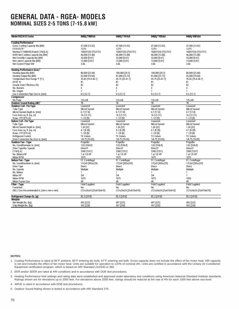
70
Model RGEA15 Series 048AJT08XAA 048AJT101AA 048AJT10XAA 048AJV081AA
Cooling Performance1 Continued -> Gross Cooling Capacity Btu [kW] 47,500 [13.92] 47,500 [13.92] 47,500 [13.92] 47,500 [13.92] EER/SEER2 12/15 12/15 12/15 12/15 Nominal CFM/AHRI Rated CFM [L/s] 1600/1550 [755/731] 1600/1550 [755/731] 1600/1550 [755/731] 1600/1550 [755/731] AHRI Net Cooling Capacity Btu [kW] 46,000 [13.48] 46,000 [13.48] 46,000 [13.48] 46,000 [13.48] Net Sensible Capacity Btu [kW] 33,000 [9.67] 33,000 [9.67] 33,000 [9.67] 33,000 [9.67] Net Latent Capacity Btu [kW] 13,000 [3.81] 13,000 [3.81] 13,000 [3.81] 13,000 [3.81] Net System Power kW 3.66 3.66 3.66 3.66
Heating Performance (Gas) 4
Heating Input Btu [kW] 80,000 [23.44] 100,000 [29.3] 100,000 [29.3] 80,000 [23.44] Heating Output Btu [kW] 65,000 [19.04] 81,000 [23.73] 81,000 [23.73] 65,000 [19.04] Temperature Rise Range ºF [ºC] 35-65 [19.4-36.1] 45-75 [25-41.7] 45-75 [25-41.7] 35-65 [19.4-36.1] AFUE % 81 81 81 81 Steady State Efficiency (%) 82 82 82 82 No. Burners 4 4 4 4 No. Stages 1 1 1 1 Gas Connection Pipe Size in. [mm] 0.5 [12.7] 0.5 [12.7] 0.5 [12.7] 0.5 [12.7]Compressor No./Type 1/Scroll 1/Scroll 1/Scroll 1/ScrollOutdoor Sound Rating (dB)5 78 78 78 78Outdoor Coil - Fin Type Louvered Louvered Louvered Louvered Tube Type MicroChannel MicroChannel MicroChannel MicroChannel MicroChannel Depth in. [mm] 0.7 [17.8] 0.7 [17.8] 0.7 [17.8] 0.7 [17.8] Face Area sq. ft. [sq. m] 16.3 [1.51] 16.3 [1.51] 16.3 [1.51] 16.3 [1.51] Rows / FPI [FPcm] 1 / 23 [9] 1 / 23 [9] 1 / 23 [9] 1 / 23 [9]Indoor Coil - Fin Type Louvered Louvered Louvered Louvered Tube Type MicroChannel MicroChannel MicroChannel MicroChannel MicroChannel Depth in. [mm] 1.26 [32] 1.26 [32] 1.26 [32] 1.26 [32] Face Area sq. ft. [sq. m] 4.1 [0.38] 4.1 [0.38] 4.1 [0.38] 4.1 [0.38] Rows / FPI [FPcm] 1 / 20 [8] 1 / 20 [8] 1 / 20 [8] 1 / 20 [8] Refrigerant Control TX Valves TX Valves TX Valves TX Valves Drain Connection No./Size in. [mm] 1/0.75 [19.05] 1/0.75 [19.05] 1/0.75 [19.05] 1/0.75 [19.05]Outdoor Fan - Type Propeller Propeller Propeller Propeller No. Used/Diameter in. [mm] 1/22 [558.8] 1/22 [558.8] 1/22 [558.8] 1/22 [558.8] Drive Type/No. Speeds Direct/1 Direct/1 Direct/1 Direct/1 CFM [L/s] 3300 [1557] 3300 [1557] 3300 [1557] 3300 [1557] No. Motors/HP 1 at 1/3 HP 1 at 1/3 HP 1 at 1/3 HP 1 at 1/3 HP Motor RPM 1075 1075 1075 1075Indoor Fan - Type FC Centrifugal FC Centrifugal FC Centrifugal FC Centrifugal No. Used/Diameter in. [mm] 1/12x9 [305x229] 1/12x9 [305x229] 1/12x9 [305x229] 1/12x9 [305x229] Drive Type Direct Direct Direct Direct No. Speeds Multiple Multiple Multiple Multiple No. Motors 1 1 1 1 Motor HP 3/4 3/4 3/4 1 Motor RPM 1075 1075 1075 1050 Motor Frame Size 48 48 48 48Filter - Type Field Supplied Field Supplied Field Supplied Field Supplied Furnished No No No No (NO.) Size Recommended in. [mm x mm x mm] (1)1x24x24 [25x610x610] (1)1x24x24 [25x610x610] (1)1x24x24 [25x610x610] (1)1x24x24 [25x610x610]
Refrigerant Charge Oz. [g] 85.3 [2418] 85.3 [2418] 85.3 [2418] 85.3 [2418]Weights Net Weight lbs. [kg] 492 [223] 497 [225] 497 [225] 492 [223] Ship Weight lbs. [kg] 502 [228] 507 [230] 507 [230] 502 [228]
GENERAL DATA - RGEA- MODELSNOMINAL SIZES 2-5 TONS [7-15.8 kW]
NOTES:
1. Cooling Performance is rated at 95°F ambient, 80°F entering dry bulb, 67°F entering wet bulb. Gross capacity does not include the effect of fan motor heat. ARI capacityis net and includes the effect of fan motor heat. Units are suitable for operation to ±20% of nominal cfm. Units are certified in accordance with the Unitary Air ConditionerEquipment certification program, which is based on ARI Standard 210/240 or 360.
2. EER and/or SEER are rated at ARI conditions and in accordance with DOE test procedures.
3. Heating Performance limit settings and rating data were established and approved under laboratory test conditions using American National Standard Institute standards.Ratings shown are for elevations up to 2000 feet. For elevations above 2000 feet, ratings should be reduced at the rate of 4% for each 1000 feet above sea level.
4. ARUE is rated in accordance with DOE test procedures.
5. Outdoor Sound Rating shown is tested in accordance with ARI Standard 270.

71
Model RGEA15 Series 048AJV08XAA 048AJV101AA 048AJV10XAA
Cooling Performance1 Continued -> Gross Cooling Capacity Btu [kW] 47,500 [13.92] 47,500 [13.92] 47,500 [13.92] EER/SEER2 12/15 12/15 12/15 Nominal CFM/AHRI Rated CFM [L/s] 1600/1550 [755/731] 1600/1550 [755/731] 1600/1550 [755/731] AHRI Net Cooling Capacity Btu [kW] 46,000 [13.48] 46,000 [13.48] 46,000 [13.48] Net Sensible Capacity Btu [kW] 33,000 [9.67] 33,000 [9.67] 33,000 [9.67] Net Latent Capacity Btu [kW] 13,000 [3.81] 13,000 [3.81] 13,000 [3.81] Net System Power kW 3.66 3.66 3.66
Heating Performance (Gas) 4
Heating Input Btu [kW] 80,000 [23.44] 100,000 [29.3] 100,000 [29.3] Heating Output Btu [kW] 65,000 [19.04] 81,000 [23.73] 81,000 [23.73] Temperature Rise Range ºF [ºC] 35-65 [19.4-36.1] 45-75 [25-41.7] 45-75 [25-41.7] AFUE % 81 81 81 Steady State Efficiency (%) 82 82 82 No. Burners 4 4 4 No. Stages 1 1 1 Gas Connection Pipe Size in. [mm] 0.5 [12.7] 0.5 [12.7] 0.5 [12.7]Compressor No./Type 1/Scroll 1/Scroll 1/ScrollOutdoor Sound Rating (dB)5 78 78 78Outdoor Coil - Fin Type Louvered Louvered Louvered Tube Type MicroChannel MicroChannel MicroChannel MicroChannel Depth in. [mm] 0.7 [17.8] 0.7 [17.8] 0.7 [17.8] Face Area sq. ft. [sq. m] 16.3 [1.51] 16.3 [1.51] 16.3 [1.51] Rows / FPI [FPcm] 1 / 23 [9] 1 / 23 [9] 1 / 23 [9]Indoor Coil - Fin Type Louvered Louvered Louvered Tube Type MicroChannel MicroChannel MicroChannel MicroChannel Depth in. [mm] 1.26 [32] 1.26 [32] 1.26 [32] Face Area sq. ft. [sq. m] 4.1 [0.38] 4.1 [0.38] 4.1 [0.38] Rows / FPI [FPcm] 1 / 20 [8] 1 / 20 [8] 1 / 20 [8] Refrigerant Control TX Valves TX Valves TX Valves Drain Connection No./Size in. [mm] 1/0.75 [19.05] 1/0.75 [19.05] 1/0.75 [19.05]Outdoor Fan - Type Propeller Propeller Propeller No. Used/Diameter in. [mm] 1/22 [558.8] 1/22 [558.8] 1/22 [558.8] Drive Type/No. Speeds Direct/1 Direct/1 Direct/1 CFM [L/s] 3300 [1557] 3300 [1557] 3300 [1557] No. Motors/HP 1 at 1/3 HP 1 at 1/3 HP 1 at 1/3 HP Motor RPM 1075 1075 1075Indoor Fan - Type FC Centrifugal FC Centrifugal FC Centrifugal No. Used/Diameter in. [mm] 1/12x9 [305x229] 1/12x9 [305x229] 1/12x9 [305x229] Drive Type Direct Direct Direct No. Speeds Multiple Multiple Multiple No. Motors 1 1 1 Motor HP 1 1 1 Motor RPM 1050 1050 1050 Motor Frame Size 48 48 48Filter - Type Field Supplied Field Supplied Field Supplied Furnished No No No (NO.) Size Recommended in. [mm x mm x mm] (1)1x24x24 [25x610x610] (1)1x24x24 [25x610x610] (1)1x24x24 [25x610x610]
Refrigerant Charge Oz. [g] 85.3 [2418] 85.3 [2418] 85.3 [2418]Weights Net Weight lbs. [kg] 492 [223] 497 [225] 497 [225] Ship Weight lbs. [kg] 502 [228] 507 [230] 507 [230]
GENERAL DATA - RGEA- MODELSNOMINAL SIZES 2-5 TONS [7-15.8 kW]
NOTES:
1. Cooling Performance is rated at 95°F ambient, 80°F entering dry bulb, 67°F entering wet bulb. Gross capacity does not include the effect of fan motor heat. ARI capacityis net and includes the effect of fan motor heat. Units are suitable for operation to ±20% of nominal cfm. Units are certified in accordance with the Unitary Air ConditionerEquipment certification program, which is based on ARI Standard 210/240 or 360.
2. EER and/or SEER are rated at ARI conditions and in accordance with DOE test procedures.
3. Heating Performance limit settings and rating data were established and approved under laboratory test conditions using American National Standard Institute standards.Ratings shown are for elevations up to 2000 feet. For elevations above 2000 feet, ratings should be reduced at the rate of 4% for each 1000 feet above sea level.
4. ARUE is rated in accordance with DOE test procedures.
5. Outdoor Sound Rating shown is tested in accordance with ARI Standard 270.
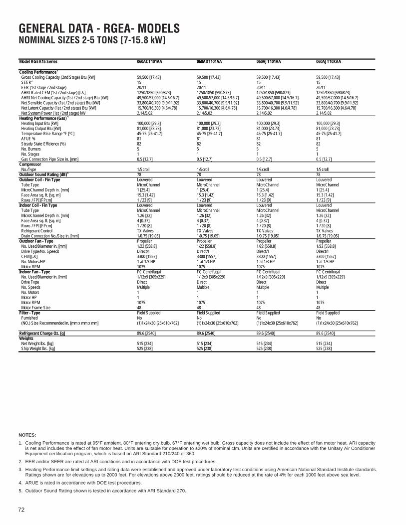
72
Model RGEA15 Series 060ACT101AA 060ADT101AA 060AJT101AA 060AJT10XAA
Cooling Performance1 Continued -> Gross Cooling Capacity (2nd Stage) Btu [kW] 59,500 [17.43] 59,500 [17.43] 59,500 [17.43] 59,500 [17.43] SEER2 15 15 15 15 EER (1st stage / 2nd stage) 20/11 20/11 20/11 20/11 AHRI Rated CFM (1st / 2nd stage) [L/s] 1250/1850 [590/873] 1250/1850 [590/873] 1250/1850 [590/873] 1250/1850 [590/873] AHRI Net Cooling Capacity (1st / 2nd stage) Btu [kW] 49,500/57,000 [14.5/16.7] 49,500/57,000 [14.5/16.7] 49,500/57,000 [14.5/16.7] 49,500/57,000 [14.5/16.7] Net Sensible Capacity (1st / 2nd stage) Btu [kW] 33,800/40,700 [9.9/11.92] 33,800/40,700 [9.9/11.92] 33,800/40,700 [9.9/11.92] 33,800/40,700 [9.9/11.92] Net Latent Capacity (1st / 2nd stage) Btu [kW] 15,700/16,300 [4.6/4.78] 15,700/16,300 [4.6/4.78] 15,700/16,300 [4.6/4.78] 15,700/16,300 [4.6/4.78] Net System Power (1st / 2nd stage) kW 2.14/5.02 2.14/5.02 2.14/5.02 2.14/5.02Heating Performance (Gas) 4
Heating Input Btu [kW] 100,000 [29.3] 100,000 [29.3] 100,000 [29.3] 100,000 [29.3] Heating Output Btu [kW] 81,000 [23.73] 81,000 [23.73] 81,000 [23.73] 81,000 [23.73] Temperature Rise Range ºF [ºC] 45-75 [25-41.7] 45-75 [25-41.7] 45-75 [25-41.7] 45-75 [25-41.7] AFUE % 81 81 81 81 Steady State Efficiency (%) 82 82 82 82 No. Burners 5 5 5 5 No. Stages 1 1 1 1 Gas Connection Pipe Size in. [mm] 0.5 [12.7] 0.5 [12.7] 0.5 [12.7] 0.5 [12.7]Compressor No./Type 1/Scroll 1/Scroll 1/Scroll 1/ScrollOutdoor Sound Rating (dB)5 78 78 78 78Outdoor Coil - Fin Type Louvered Louvered Louvered Louvered Tube Type MicroChannel MicroChannel MicroChannel MicroChannel MicroChannel Depth in. [mm] 1 [25.4] 1 [25.4] 1 [25.4] 1 [25.4] Face Area sq. ft. [sq. m] 15.3 [1.42] 15.3 [1.42] 15.3 [1.42] 15.3 [1.42] Rows / FPI [FPcm] 1 / 23 [9] 1 / 23 [9] 1 / 23 [9] 1 / 23 [9]Indoor Coil - Fin Type Louvered Louvered Louvered Louvered Tube Type MicroChannel MicroChannel MicroChannel MicroChannel MicroChannel Depth in. [mm] 1.26 [32] 1.26 [32] 1.26 [32] 1.26 [32] Face Area sq. ft. [sq. m] 4 [0.37] 4 [0.37] 4 [0.37] 4 [0.37] Rows / FPI [FPcm] 1 / 20 [8] 1 / 20 [8] 1 / 20 [8] 1 / 20 [8] Refrigerant Control TX Valves TX Valves TX Valves TX Valves Drain Connection No./Size in. [mm] 1/0.75 [19.05] 1/0.75 [19.05] 1/0.75 [19.05] 1/0.75 [19.05]Outdoor Fan - Type Propeller Propeller Propeller Propeller No. Used/Diameter in. [mm] 1/22 [558.8] 1/22 [558.8] 1/22 [558.8] 1/22 [558.8] Drive Type/No. Speeds Direct/1 Direct/1 Direct/1 Direct/1 CFM [L/s] 3300 [1557] 3300 [1557] 3300 [1557] 3300 [1557] No. Motors/HP 1 at 1/3 HP 1 at 1/3 HP 1 at 1/3 HP 1 at 1/3 HP Motor RPM 1075 1075 1075 1075Indoor Fan - Type FC Centrifugal FC Centrifugal FC Centrifugal FC Centrifugal No. Used/Diameter in. [mm] 1/12x9 [305x229] 1/12x9 [305x229] 1/12x9 [305x229] 1/12x9 [305x229] Drive Type Direct Direct Direct Direct No. Speeds Multiple Multiple Multiple Multiple No. Motors 1 1 1 1 Motor HP 1 1 1 1 Motor RPM 1075 1075 1075 1075 Motor Frame Size 48 48 48 48Filter - Type Field Supplied Field Supplied Field Supplied Field Supplied Furnished No No No No (NO.) Size Recommended in. [mm x mm x mm] (1)1x24x30 [25x610x762] (1)1x24x30 [25x610x762] (1)1x24x30 [25x610x762] (1)1x24x30 [25x610x762]
Refrigerant Charge Oz. [g] 89.6 [2540] 89.6 [2540] 89.6 [2540] 89.6 [2540]Weights Net Weight lbs. [kg] 515 [234] 515 [234] 515 [234] 515 [234] Ship Weight lbs. [kg] 525 [238] 525 [238] 525 [238] 525 [238]
GENERAL DATA - RGEA- MODELSNOMINAL SIZES 2-5 TONS [7-15.8 kW]
NOTES:
1. Cooling Performance is rated at 95°F ambient, 80°F entering dry bulb, 67°F entering wet bulb. Gross capacity does not include the effect of fan motor heat. ARI capacityis net and includes the effect of fan motor heat. Units are suitable for operation to ±20% of nominal cfm. Units are certified in accordance with the Unitary Air ConditionerEquipment certification program, which is based on ARI Standard 210/240 or 360.
2. EER and/or SEER are rated at ARI conditions and in accordance with DOE test procedures.
3. Heating Performance limit settings and rating data were established and approved under laboratory test conditions using American National Standard Institute standards.Ratings shown are for elevations up to 2000 feet. For elevations above 2000 feet, ratings should be reduced at the rate of 4% for each 1000 feet above sea level.
4. ARUE is rated in accordance with DOE test procedures.
5. Outdoor Sound Rating shown is tested in accordance with ARI Standard 270.

73
Model RGEA15 Series 060AJV101AA 060AJV10XAA
Cooling Performance1
Gross Cooling Capacity (2nd Stage) Btu [kW] 59,500 [17.43] 59,500 [17.43] SEER2 15 15 EER (1st stage / 2nd stage) 20/11 20/11 AHRI Rated CFM (1st / 2nd stage) [L/s] 1250/1850 [590/873] 1250/1850 [590/873] AHRI Net Cooling Capacity (1st / 2nd stage) Btu [kW] 49,500/57,000 [14.5/16.7] 49,500/57,000 [14.5/16.7] Net Sensible Capacity (1st / 2nd stage) Btu [kW] 33,800/40,700 [9.9/11.92] 33,800/40,700 [9.9/11.92] Net Latent Capacity (1st / 2nd stage) Btu [kW] 15,700/16,300 [4.6/4.78] 15,700/16,300 [4.6/4.78] Net System Power (1st / 2nd stage) kW 2.14/5.02 2.14/5.02Heating Performance (Gas) 4
Heating Input Btu [kW] 100,000 [29.3] 100,000 [29.3] Heating Output Btu [kW] 81,000 [23.73] 81,000 [23.73] Temperature Rise Range ºF [ºC] 45-75 [25-41.7] 45-75 [25-41.7] AFUE % 81 81 Steady State Efficiency (%) 82 82 No. Burners 5 5 No. Stages 1 1 Gas Connection Pipe Size in. [mm] 0.5 [12.7] 0.5 [12.7]Compressor No./Type 1/Scroll 1/ScrollOutdoor Sound Rating (dB)5 78 78Outdoor Coil - Fin Type Louvered Louvered Tube Type MicroChannel MicroChannel MicroChannel Depth in. [mm] 1 [25.4] 1 [25.4] Face Area sq. ft. [sq. m] 15.3 [1.42] 15.3 [1.42] Rows / FPI [FPcm] 1 / 23 [9] 1 / 23 [9]Indoor Coil - Fin Type Louvered Louvered Tube Type MicroChannel MicroChannel MicroChannel Depth in. [mm] 1.26 [32] 1.26 [32] Face Area sq. ft. [sq. m] 4 [0.37] 4 [0.37] Rows / FPI [FPcm] 1 / 20 [8] 1 / 20 [8] Refrigerant Control TX Valves TX Valves Drain Connection No./Size in. [mm] 1/0.75 [19.05] 1/0.75 [19.05]Outdoor Fan - Type Propeller Propeller No. Used/Diameter in. [mm] 1/22 [558.8] 1/22 [558.8] Drive Type/No. Speeds Direct/1 Direct/1 CFM [L/s] 3300 [1557] 3300 [1557] No. Motors/HP 1 at 1/3 HP 1 at 1/3 HP Motor RPM 1075 1075Indoor Fan - Type FC Centrifugal FC Centrifugal No. Used/Diameter in. [mm] 1/12x9 [305x229] 1/12x9 [305x229] Drive Type Direct Direct No. Speeds Multiple Multiple No. Motors 1 1 Motor HP 1 1 Motor RPM 1050 1050 Motor Frame Size 48 48Filter - Type Field Supplied Field Supplied Furnished No No (NO.) Size Recommended in. [mm x mm x mm] (1)1x24x30 [25x610x762] (1)1x24x30 [25x610x762]
Refrigerant Charge Oz. [g] 89.6 [2540] 89.6 [2540]Weights Net Weight lbs. [kg] 515 [234] 515 [234] Ship Weight lbs. [kg] 525 [238] 525 [238]
GENERAL DATA - RGEA- MODELSNOMINAL SIZES 2-5 TONS [7-15.8 kW]
NOTES:
1. Cooling Performance is rated at 95°F ambient, 80°F entering dry bulb, 67°F entering wet bulb. Gross capacity does not include the effect of fan motor heat. ARI capacityis net and includes the effect of fan motor heat. Units are suitable for operation to ±20% of nominal cfm. Units are certified in accordance with the Unitary Air ConditionerEquipment certification program, which is based on ARI Standard 210/240 or 360.
2. EER and/or SEER are rated at ARI conditions and in accordance with DOE test procedures.
3. Heating Performance limit settings and rating data were established and approved under laboratory test conditions using American National Standard Institute standards.Ratings shown are for elevations up to 2000 feet. For elevations above 2000 feet, ratings should be reduced at the rate of 4% for each 1000 feet above sea level.
4. ARUE is rated in accordance with DOE test procedures.
5. Outdoor Sound Rating shown is tested in accordance with ARI Standard 270.

74
XIII. MISCELLANEOUS
ELECTRICAL DATA - RGEA13 SERIES024AJD***AA 030AJD***AA 036ACD***AA 036ADD***AA 036AJD***AA 042ACT***AA 042AJT***AA 048ACT***AA 048ADT***AA
Unit I
nform
ation
Unit Operating Voltage Range 187-253 187-253 187-253 414-506 187-253 187-253 187-253 187-253 187-253
Volts 208/230 208/230 208/230 460 208/230 208/230 208/230 208/230 460Phase 1 1 3 3 1 3 1 3 3
Hz 60 60 60 60 60 60 60 60 60Minimum Circuit Ampacity 17 20 16 9 22 24 30 25 12
Minimum Overcurrent Protection Device Size 20 20 20 15 25 25 30 25 35
Maximum Overcurrent Protection Device Size 25 30 20 15 35 35 45 35 15
Comp
ress
or M
otor
No. 1 1 1 1 1 1 1 1 1Volts 208/230 208/230 208/230 460 208/230 208/230 208/230 208/230 460
Phase 1 1 3 3 1 3 1 3 3RPM 3450 3450 3450 3450 3450 3450 3450 3450 3450
HP, Compressor 1 2 1/6 2 2/3 3 1/3 3 1/3 3 1/3 3 1/2 3 1/2 4 4Amps (RLA), Comp. 1 11.2 12.8 9 5.6 14.1 13.2 17.9 13.1 6.1Amps (LRA), Comp. 1 60.8 64 71 38 77 88 112 83.1 41
Cond
ense
r Mot
or
No. 1 1 1 1 1 1 1 1 1Volts 208/230 208/230 208/230 460 208/230 208/230 208/230 208/230 460
Phase 1 1 1 1 1 1 1 1 1HP 1/3 1/3 1/3 1/3 1/3 1/3 1/3 1/3 1/3
Amps (FLA, each) 1.5 1.5 1.5 0.8 1.5 1.5 1.5 2 1Amps (LRA, each) 3 3 3 1.6 3 3 3 3.9 2.2
Evap
orat
or F
an
No. 1 1 1 1 1 1 1 1 1Volts 208/230 208/230 208/230 460 208/230 208/230 208/230 208/230 460
Phase 1 1 1 1 1 1 1 1 1HP 1/4 1/2 1/2 1/2 1/2 3/4 3/4 3/4 3/4
Amps (FLA, each) 1.3 2.4 2.5 1.2 2.5 6 6 6 3.2Amps (LRA, each) 2.3 5.1 4.6 2.4 4.6
ELECTRICAL DATA - RGEA13 SERIES048AJT***AA 060ACT***AA 060ADT***AA 060AJT***AA
Unit I
nform
ation
Unit Operating Voltage Range 187-253 197-253 414-506 197-253
Volts 208/230 208/230 460 208/230Phase 1 3 3 1
Hz 60 60 60 60Minimum Circuit Ampacity 33 32 16 41
Minimum Overcurrent Protection Device Size 35 35 20 45
Maximum Overcurrent Protection Device Size 50 45 20 60
Comp
ress
or M
otor
No. 1 1 1 1Volts 208/230 208/230 460 208/230
Phase 1 3 3 1RPM 3450 3500 3500 3500
HP, Compressor 1 4 5 5 5Amps (RLA), Comp. 1 19.9 17.8 8.6 24.4Amps (LRA), Comp. 1 109 110 52 144.2
Cond
ense
r Mot
or
No. 1 1 1 1Volts 208/230 208/230 460 208/230
Phase 1 1 1 1HP 1/3 1/3 1/3 1/3
Amps (FLA, each) 2 2 1 2Amps (LRA, each) 3.9 3.9 2.2 3.9
Evap
orat
or F
an
No. 1 1 1 1Volts 208/230 208/230 460/460 208/230
Phase 1 1 1 1HP 3/4 1 1 1
Amps (FLA, each) 6 7.6 4 7.6Amps (LRA, each)
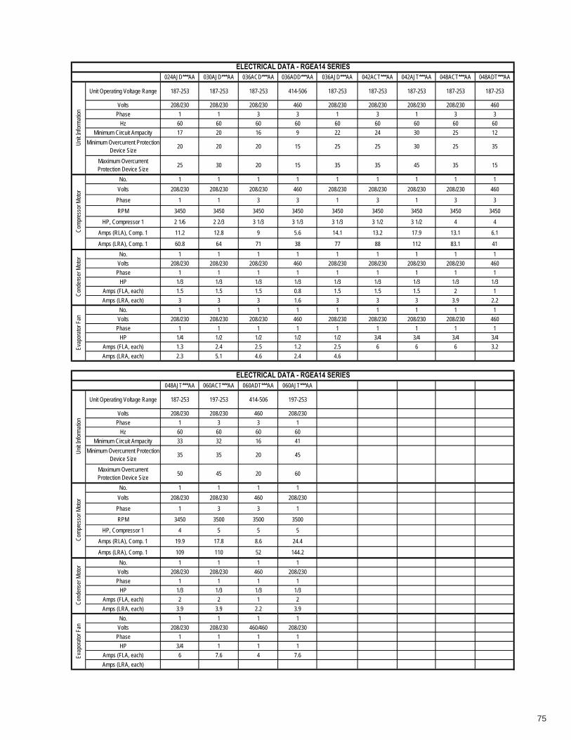
75
ELECTRICAL DATA - RGEA14 SERIES024AJD***AA 030AJD***AA 036ACD***AA 036ADD***AA 036AJD***AA 042ACT***AA 042AJT***AA 048ACT***AA 048ADT***AA
Unit I
nform
ation
Unit Operating Voltage Range 187-253 187-253 187-253 414-506 187-253 187-253 187-253 187-253 187-253
Volts 208/230 208/230 208/230 460 208/230 208/230 208/230 208/230 460Phase 1 1 3 3 1 3 1 3 3
Hz 60 60 60 60 60 60 60 60 60Minimum Circuit Ampacity 17 20 16 9 22 24 30 25 12
Minimum Overcurrent Protection Device Size 20 20 20 15 25 25 30 25 35
Maximum Overcurrent Protection Device Size 25 30 20 15 35 35 45 35 15
Comp
ress
or M
otor
No. 1 1 1 1 1 1 1 1 1Volts 208/230 208/230 208/230 460 208/230 208/230 208/230 208/230 460
Phase 1 1 3 3 1 3 1 3 3
RPM 3450 3450 3450 3450 3450 3450 3450 3450 3450
HP, Compressor 1 2 1/6 2 2/3 3 1/3 3 1/3 3 1/3 3 1/2 3 1/2 4 4
Amps (RLA), Comp. 1 11.2 12.8 9 5.6 14.1 13.2 17.9 13.1 6.1
Amps (LRA), Comp. 1 60.8 64 71 38 77 88 112 83.1 41
Cond
ense
r Moto
r No. 1 1 1 1 1 1 1 1 1Volts 208/230 208/230 208/230 460 208/230 208/230 208/230 208/230 460
Phase 1 1 1 1 1 1 1 1 1HP 1/3 1/3 1/3 1/3 1/3 1/3 1/3 1/3 1/3
Amps (FLA, each) 1.5 1.5 1.5 0.8 1.5 1.5 1.5 2 1Amps (LRA, each) 3 3 3 1.6 3 3 3 3.9 2.2
Evap
orato
r Fan
No. 1 1 1 1 1 1 1 1 1Volts 208/230 208/230 208/230 460 208/230 208/230 208/230 208/230 460
Phase 1 1 1 1 1 1 1 1 1HP 1/4 1/2 1/2 1/2 1/2 3/4 3/4 3/4 3/4
Amps (FLA, each) 1.3 2.4 2.5 1.2 2.5 6 6 6 3.2Amps (LRA, each) 2.3 5.1 4.6 2.4 4.6
ELECTRICAL DATA - RGEA14 SERIES048AJT***AA 060ACT***AA 060ADT***AA 060AJT***AA
Unit I
nform
ation
Unit Operating Voltage Range 187-253 197-253 414-506 197-253
Volts 208/230 208/230 460 208/230Phase 1 3 3 1
Hz 60 60 60 60Minimum Circuit Ampacity 33 32 16 41
Minimum Overcurrent Protection Device Size 35 35 20 45
Maximum Overcurrent Protection Device Size 50 45 20 60
Comp
ress
or M
otor
No. 1 1 1 1Volts 208/230 208/230 460 208/230
Phase 1 3 3 1
RPM 3450 3500 3500 3500
HP, Compressor 1 4 5 5 5
Amps (RLA), Comp. 1 19.9 17.8 8.6 24.4
Amps (LRA), Comp. 1 109 110 52 144.2
Cond
ense
r Moto
r No. 1 1 1 1Volts 208/230 208/230 460 208/230
Phase 1 1 1 1HP 1/3 1/3 1/3 1/3
Amps (FLA, each) 2 2 1 2Amps (LRA, each) 3.9 3.9 2.2 3.9
Evap
orato
r Fan
No. 1 1 1 1Volts 208/230 208/230 460/460 208/230
Phase 1 1 1 1HP 3/4 1 1 1
Amps (FLA, each) 6 7.6 4 7.6Amps (LRA, each)

76
024AJT***AA 024AJV***AA 030AJT***AA 030AJV***AA 036ACT***AA 036ADT***AA 036AJT***AA 036AJV060AA 036AJV080AA
036AJV100AA
Unit Operating Voltage Range 187-253 187-253 187-253 187-253 187-253 414-506 187-253 187-253 187-253
Volts 208/230 208/230 208/230 208/230 208/230 460 208/230 208/230 208/230
Phase 1 1 1 1 3 3 1 1 1
Hz 60 60 60 60 60 60 60 60 60
Minimum Circuit Ampacity 19 19 21 21 17 10 24 23 24
Minimum Overcurrent Protection Device Size 20 25 25 25 20 15 25 30 30
Maximum Overcurrent Protection Device Size 25 30 30 30 25 15 35 35 35
No. 1 1 1 1 1 1 1 1 1
Volts 208/230 208/230 208/230 208/230 208/230 460 208/230 208/230 208/230
Phase 1 1 1 1 3 3 1 1 1
RPM 3450 3450 3450 3450 3450 3450 3450 3450 3450
HP, Compressor 1 2 1/6 2 1/6 2 2/3 2 2/3 3 1/3 3 1/3 3 1/3 3 1/3 3 1/3
Amps (RLA), Comp. 1 11.2 11.2 12.8 12.8 9 5.6 14.1 14.1 14.1
Amps (LRA), Comp. 1 60.8 60.8 64 64 71 38 77 77 77
HP, Compressor 2
Amps (RLA), Comp. 2
Amps (LRA), Comp. 2
No. 1 1 1 1 1 1 1 1 1
Volts 208/230 208/230 208/230 208/230 208/230 460 208/230 208/230 208/230
Phase 1 1 1 1 1 1 1 1 1
HP 1/3 1/3 1/3 1/3 1/3 1/3 1/3 1/3 1/3
Amps (FLA, each) 1.5 1.5 1.5 1.5 1.5 0.8 1.5 1.5 1.5
Amps (LRA, each) 3 3 3 3 3 1.6 3 3 3
No. 1 1 1 1 1 1 1 1 1
Volts 208/230 208/230 208/230 208/230 208/230 460/460 208/230 208/230 208/230
Phase 1 1 1 1 1 1 1 1 1
HP 1/3 1/2 1/2 1/2 1/2 1/2 1/2 1/2 1/2
Amps (FLA, each) 2.8 3.5 2.8 3.5 4.1 2.1 4.1 3.5 4.0
Amps (LRA, each)
ELECTRICAL DATA - RGEA15 SERIESUn
it Info
rmati
onCo
mpre
ssor
Moto
rCo
nden
ser M
otor
Evap
orato
r Fan

77
042ACT***AA 042AJT***AA 042AJV***AA 048ACT***AA 048ADT***AA 048AJT***AA 048AJV***AA 060ACT***AA 060ADT***AA
Unit Operating Voltage Range 187-253 187-253 187-253 187-253 414-506 187-253 187-253 197-253 414-506
Volts 208/230 208/230 208/230 208/230 460 208/230 208/230 208/230 460
Phase 3 1 1 3 3 1 1 3 3
Hz 60 60 60 60 60 60 60 60 60
Minimum Circuit Ampacity 24 30 28 25 12 33 34 30 15
Minimum Overcurrent Protection Device Size 25 30 35 25 35 35 40 50 20
Maximum Overcurrent Protection Device Size 35 45 45 35 15 50 50 45 20
No. 1 1 1 1 1 1 1 1 1
Volts 208/230 208/230 208/230 208/230 460 208/230 208/230 208/230 460
Phase 3 1 1 3 1 1 1 3 3
RPM 3450 3450 3450 3450 3450 3450 3450 3450 3450
HP, Compressor 1 3 1/2 3 1/2 3 1/2 4 4 4 4 5 5
Amps (RLA), Comp. 1 13.2 17.9 17.9 13.1 6.1 19.9 19.9 16.2 7.6
Amps (LRA), Comp. 1 88 112 112 83.1 43 109 109 110 52
HP, Compressor 2
Amps (RLA), Comp. 2
Amps (LRA), Comp. 2
No. 1 1 1 1 1 1 1 1 1
Volts 208/230 208/230 208/230 208/230 460 208/230 208/230 208/230 460
Phase 1 1 1 1 1 1 1 1 1
HP 1/3 1/3 1/3 1/3 1/3 1/3 1/3 1/3 1/3
Amps (FLA, each) 1.5 1.5 1.5 2 1 2 2 2 1
Amps (LRA, each) 3 3 3 3.9 3.9 3.9 3.9 3.9 2.2
No. 1 1 1 1 1 1 1 1 1
Volts 208/230 208/230 208/230 208/230 460 208/230 208/230 208/230 460/460
Phase 1 1 1 1 1 1 1 1 1
HP 3/4 3/4 3/4 3/4 3/4 3/4 1 1 1
Amps (FLA, each) 6 6 4 6 3.2 6 6.8 7.6 4
Amps (LRA, each)
Cond
ense
r Moto
rEv
apor
ator F
anUn
it Info
rmati
onCo
mpre
ssor
Moto
rELECTRICAL DATA - RGEA15 SERIES

78
060AJT***AA 060AJV***AA
Unit Operating Voltage Range 197-253 197-253
Volts 208/230 208/230
Phase 1 1
Hz 60 60
Minimum Circuit Ampacity 46 45
Minimum Overcurrent Protection Device Size 50 60
Maximum Overcurrent Protection Device Size 70 70
No. 1 1
Volts 208/230 208/230
Phase 1 1
RPM 3450 3450
HP, Compressor 1 5 5
Amps (RLA), Comp. 1 28.8 28.8
Amps (LRA), Comp. 1 152.9 152.9
HP, Compressor 2
Amps (RLA), Comp. 2
Amps (LRA), Comp. 2
No. 1 1
Volts 208/230 208/230
Phase 1 1
HP 1/3 1/3
Amps (FLA, each) 2 2
Amps (LRA, each) 3.9 3.9
No. 1 1
Volts 208/230 208/230
Phase 1 1
HP 1 1
Amps (FLA, each) 7.6 6.8
Amps (LRA, each)
Evap
orato
r Fan
ELECTRICAL DATA - RGEA15 SERIESUn
it Info
rmati
onCo
mpre
ssor
Moto
rCo
nden
ser M
otor

79
XIV. AIRFLOW PERFORMANCE DATAINDOOR AIRFLOW PERFORMANCE FOR 2-5 TON PACKAGE GAS ELECTRIC UNITS–RGEA-
DIRECT DRIVE
Coo
lH
eat
0.1
[.02]
0.2
[.05]
0.3
[.07]
0.4
[.10]
0.5
[.12]
0.6
[.15]
0.7
[.17]
0.8
[.20]
0.9
[.22]
1.0
[.25]
CFM
822
[388
]78
9 [3
72]
750
[354
]69
6 [3
28]
624
[294
]49
6 [2
34]
402
[190
]R
PM
917
954
994
1031
1051
1075
1105
Wat
ts22
621
620
318
817
515
013
6C
FM99
2 [4
68]
928
[438
]87
3 [4
12]
810
[382
]74
1 [3
50]
659
[311
]49
0 [2
31]
RP
M10
5510
6810
8010
9611
0611
1911
36W
atts
271
256
245
227
214
199
175
CFM
1093
[516
]10
62 [5
01]
1001
[472
]93
0 [4
39]
815
[385
]72
8 [3
44]
663
[313
]57
1 [2
69]
RP
M90
093
596
999
910
3010
5310
6410
82W
atts
375
358
335
313
283
264
249
229
CFM
1239
[585
]11
84 [5
59]
1114
[526
]10
43 [4
92]
959
[453
]82
7 [3
90]
744
[351
]65
7 [3
10]
RP
M96
198
310
0610
3010
5210
7410
8410
97W
atts
429
409
384
360
334
303
287
266
CFM
1362
[643
]12
92 [6
10]
1213
[572
]11
33 [5
35]
1027
[485
]87
2 [4
12]
800
[378
]70
0 [3
30]
RP
M10
4910
6110
7310
8510
9711
0911
1611
24W
atts
500
472
454
427
405
371
360
339
CFM
1310
[618
]12
46 [5
88]
1186
[560
]11
28 [5
32]
1038
[490
]95
5 [4
51]
847
[400
]73
8 [3
48]
RP
M83
486
789
591
894
997
198
910
19W
atts
460
447
435
424
407
396
380
362
CFM
1644
[776
]15
68 [7
40]
1488
[702
]14
21 [6
71]
1330
[628
]12
48 [5
89]
1133
[535
]10
03 [4
73]
RP
M98
199
610
0914
2113
3012
4810
5810
72W
atts
664
641
620
1421
1330
1248
545
526
CFM
1336
[631
]13
12 [6
19]
1295
[611
]12
41 [5
86]
1200
[566
]11
61 [5
48]
1119
[528
]10
72 [5
06]
RP
M82
785
687
491
394
998
310
1310
48W
atts
298
308
313
325
341
352
361
374
CFM
1336
[631
]13
12 [6
19]
1295
[611
]12
41 [5
86]
1200
[566
]11
61 [5
48]
1119
[528
]10
72 [5
06]
RP
M82
785
687
491
394
998
310
1310
48W
atts
298
308
313
325
341
352
361
374
CFM
1453
[686
]14
24 [6
72]
1395
[658
]13
47 [6
36]
1321
[623
]12
79 [6
04]
1250
[590
]12
14 [5
73]
RP
M83
686
790
494
295
399
210
1910
48W
atts
334
349
364
377
380
394
409
418
CFM
1336
[631
]13
12 [6
19]
1295
[611
]12
41 [5
86]
1200
[566
]11
61 [5
48]
1119
[528
]10
72 [5
06]
RP
M82
785
687
491
394
998
310
1310
48W
atts
298
308
313
325
341
352
361
374
CFM
1591
[751
]15
63 [7
38]
1558
[735
]15
19 [7
17]
1490
[703
]14
58 [6
88]
1410
[665
]13
63 [6
43]
RP
M94
998
199
910
2710
5110
8611
0911
29W
atts
476
490
501
515
527
542
546
543
CFM
1368
[646
]13
31 [6
28]
1299
[613
]12
59 [5
94]
1221
[576
]11
69 [5
52]
1137
[537
]10
79 [5
09]
997
[471
]92
0 [4
34]
RP
M74
978
281
384
987
791
194
697
910
3010
61W
atts
250
264
275
286
295
308
321
327
346
356
CFM
1368
[646
]13
31 [6
28]
1299
[613
]12
59 [5
94]
1221
[576
]11
69 [5
52]
1137
[537
]10
79 [5
09]
997
[471
]92
0 [4
34]
RP
M74
978
281
384
987
791
194
697
910
3010
61W
atts
250
264
275
286
295
308
321
327
346
356
CFM
1447
[683
]14
05 [6
63]
1372
[648
]13
42 [6
33]
1307
[617
]12
37 [5
84]
1222
[577
]11
86 [5
60]
1121
[529
]10
35 [4
88]
RP
M78
380
984
587
290
593
895
999
810
3810
82W
atts
291
298
315
326
337
349
355
369
383
401
CFM
1657
[782
]16
28 [7
68]
1588
[749
]15
59 [7
36]
1519
[717
]14
96 [7
06]
1454
[686
]14
26 [6
73]
1394
[658
]13
42 [6
33]
RP
M87
289
792
695
397
710
0510
3110
6510
8011
13W
atts
417
429
444
457
462
478
488
505
509
524
CFM
1970
[930
]19
45 [9
18]
1920
[906
]18
84 [8
89]
1843
[870
]17
78 [8
39]
1704
[804
]16
42 [7
75]
1547
[730
]14
51 [6
85]
RP
M10
1110
3810
4810
7310
9211
0411
1911
2311
3211
45W
atts
696
710
731
728
727
712
693
666
627
602
CFM
1433
[676
]14
07 [6
64]
1354
[639
]13
29 [6
27]
1270
[599
]12
35 [5
83]
1195
[564
]11
37 [5
37]
1083
[511
]10
30 [4
86]
RP
M82
184
386
888
892
994
497
510
0410
4010
65W
atts
319
331
342
346
365
368
381
391
406
412
CFM
1233
[582
]11
58 [5
47]
1136
[536
]10
90 [5
14]
1039
[490
]96
9 [4
57]
902
[426
]84
7 [4
00]
791
[373
]75
2 [3
55]
RP
M73
477
479
382
286
089
293
495
798
310
11W
atts
223
231
238
248
259
269
288
284
295
306
CFM
1768
[834
]17
30 [8
16]
1693
[799
]16
26 [7
67]
1599
[755
]15
58 [7
35]
1522
[718
]15
03 [7
09]
1444
[681
]13
99 [6
60]
RP
M93
895
998
310
1110
2510
5210
8910
9011
1711
34W
atts
520
533
541
560
563
578
599
599
605
615
CFM
1926
[909
]18
90 [8
92]
1864
[880
]18
22 [8
60]
1794
[847
]17
58 [8
30]
1710
[807
]16
70 [7
88]
1579
[745
]14
93 [7
05]
RP
M99
910
1410
4010
6110
7910
9611
1911
2811
3811
44W
atts
654
660
674
688
699
708
714
705
683
661
CFM
2096
[989
]20
57 [9
71]
2003
[945
]19
51 [9
21]
1890
[892
]18
19 [8
58]
1756
[829
]16
86 [7
96]
1610
[760
]14
98 [7
07]
RP
M10
6910
9211
0611
1611
2111
2911
3811
4011
4811
54W
atts
829
846
840
822
807
782
768
730
708
679
Not
e: (1
) Set
3-1
/2 th
roug
h 5
ton
Coo
l to
Tap
4 fo
r AH
RI r
ated
per
form
ance
. (2)
Set
3 T
on C
ool t
o Lo
w fo
r AH
RI r
ated
per
form
ance
.
800
[378
]10
00 [4
72]
1200
[566
]14
00 [6
61]
1600
[755
]18
00 [8
49]
2000
[944
].0
2 [.0
05]
.05
[.012
].0
7 [.0
17]
.1 [.
025]
.12
[.030
].1
5 [.0
37]
.17
[.042
]
Indo
or A
irflo
w P
erfo
rman
ce R
GEA
13/1
4 - 2
30 V
olts
Nom
inal
Coo
ling
Cap
acity
Tons
[kW
]
Mot
or S
peed
from
Fact
ory
Hea
ting
Inpu
tB
TU/H
R [k
W]
Man
ufac
ture
rR
ecom
men
ded
Coo
ling
Airf
low
(Min
/Max
)
Blo
wer
Siz
e/M
otor
HP
[W] &
# of
Spe
eds
Mot
or
Spee
d/ T
ap
2.0
[7.0
3]H
igh
Hig
h40
,000
[11.
72]
700
CFM
/ 95
0 C
FM
Exte
rnal
Sta
tic P
ress
ure
- Inc
hes
W.C
. [kP
a](S
ide
Dis
char
ge-D
ry C
oil)
Hig
h60
,000
[17.
58]
Hig
h
9x7
Blo
wer
1/4
HP
[186
]2
Spe
ed(P
SC
Mot
or)
Low
2.5
[8.7
9]Lo
w
Low
60,0
00 [1
7.58
]
850
CFM
/ 11
50 C
FM
10x9
Blo
wer
1/2
HP
[372
]3
Spe
ed(P
SC
Mot
or)
Low
Med
3.0
[10.
55]
Hig
h
Low
60,0
00 [1
7.58
]10
00 C
FM /
1400
CFM
12x9
T B
low
er1/
2 H
P [3
72]
2 S
peed
(PS
C M
otor
)
Low
Hig
h80
,000
[23.
45]
Hig
h
3.5
[12.
31]
Tap
512
00 C
FM /
1600
CFM
12x9
T B
low
er3/
4 H
P [5
59]
5 S
peed
(Con
stan
t Tor
que)
Hig
h80
,000
[23.
45]
100,
000
[29.
31]
Hig
h
Tap
1U
nuse
d
Tap
4Lo
w S
tatic
C
ool
Tap3
100,
000
[29.
31]
Tap
310
0K
Tap
280
,000
[23.
45]
Tap
280
K
Tap
5H
igh
Sta
tic
Coo
l
Tap
1U
nuse
d
Tap
4Lo
w S
tatic
C
ool
Tap
310
0,00
0 [2
9.31
]Ta
p 3
100K
Tap
280
,000
[23.
45]
Tap
280
K
5.0
[17.
59]
Tap
5
Tap
110
0,00
0 [2
9.31
]
1600
CFM
/ 21
00 C
FM
12x9
R B
low
er1
HP
[746
]5
Spe
ed(C
onst
ant T
orqu
e)
Tap
5H
igh
Sta
tic
Coo
l
4.0
[14.
07]
Tap
513
50 C
FM /
1850
CFM
12x9
T B
low
er3/
4 H
P [5
59]
5 S
peed
(Con
stan
t Tor
que)
Tap
3Lo
w C
ool
Tap
2U
nuse
d
Tap
110
0K H
eat
Tap
4M
ed C
ool
Dow
n D
isch
arge
Pre
ssur
e D
rop
(Add
to E
xter
nal S
tatic
Pre
ssur
e)C
FM [L
/s]
Pre
ssur
e D
rop
- Inc
hes
W.C
. [kP
a]
Tap
5H
igh
Coo
l
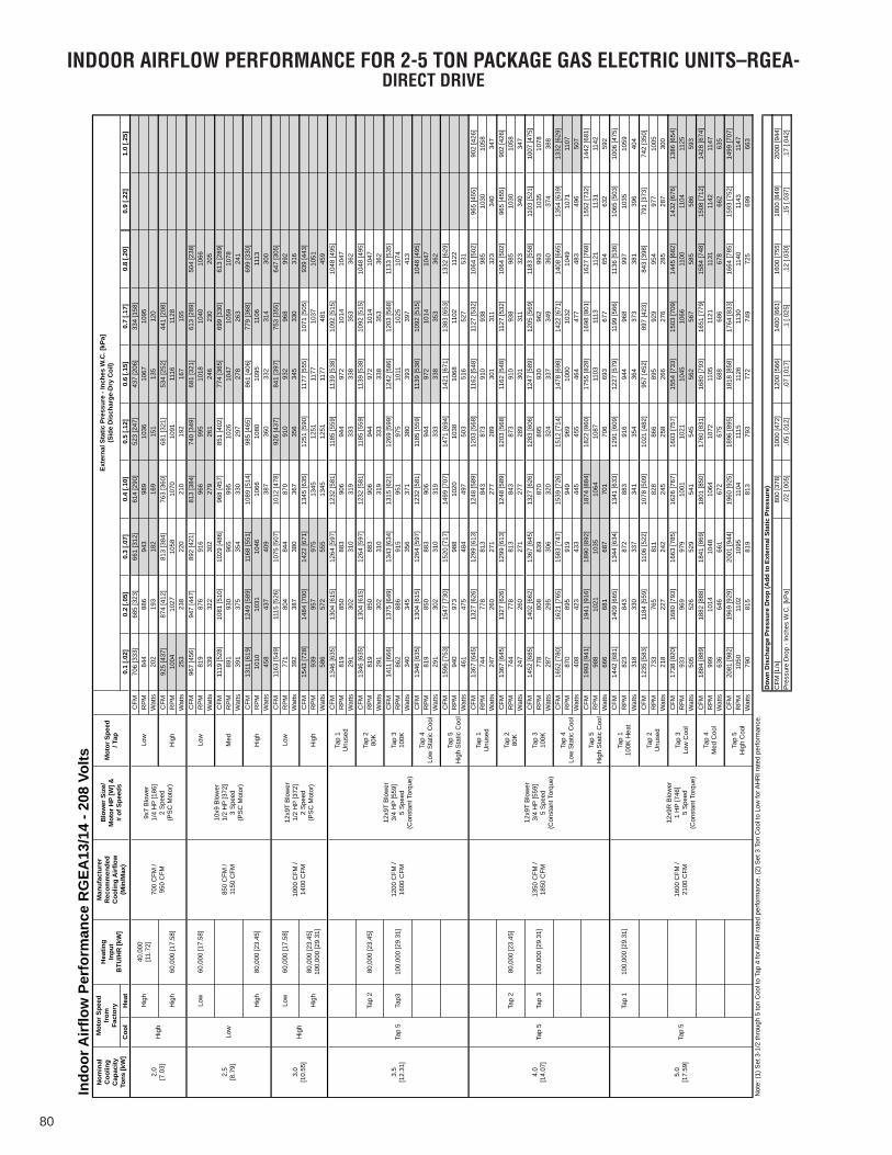
80
INDOOR AIRFLOW PERFORMANCE FOR 2-5 TON PACKAGE GAS ELECTRIC UNITS–RGEA-DIRECT DRIVE
Coo
lH
eat
0.1
[.02]
0.2
[.05]
0.3
[.07]
0.4
[.10]
0.5
[.12]
0.6
[.15]
0.7
[.17]
0.8
[.20]
0.9
[.22]
1.0
[.25]
CFM
706
[333
]68
5 [3
23]
661
[312
]61
4 [2
90]
523
[247
]43
7 [2
06]
334
[158
]R
PM
844
886
943
989
1036
1067
1095
Wat
ts20
219
318
216
915
113
512
0C
FM92
5 [4
37]
874
[412
]81
3 [3
84]
763
[360
]68
1 [3
21]
534
[252
]44
1 [2
08]
RP
M10
0410
2710
5810
7010
9111
1611
28W
atts
253
238
220
210
192
167
155
CFM
967
[456
]94
7 [4
47]
892
[421
]81
3 [3
84]
740
[349
]68
1 [3
21]
613
[289
]50
4 [2
38]
RP
M81
987
691
696
699
510
1810
4010
66W
atts
339
322
302
279
261
246
230
205
CFM
1119
[528
]10
81 [5
10]
1029
[486
]96
8 [4
57]
851
[402
]77
4 [3
65]
699
[330
]61
3 [2
89]
RP
M89
193
096
599
510
2610
4710
5910
78W
atts
391
375
354
330
297
278
263
241
CFM
1311
[619
]12
49 [5
89]
1168
[551
]10
89 [5
14]
985
[465
]86
1 [4
06]
779
[368
]69
9 [3
30]
RP
M10
1010
3110
4610
6610
8010
9511
0611
13W
atts
458
437
409
387
360
332
314
300
CFM
1163
[549
]11
15 [5
26]
1075
[507
]10
12 [4
78]
926
[437
]84
1 [3
97]
753
[355
]64
7 [3
05]
RP
M77
180
484
487
091
093
296
899
2W
atts
392
387
380
367
356
345
330
316
CFM
1543
[728
]14
84 [7
00]
1422
[671
]13
45 [6
35]
1251
[590
]11
77 [5
55]
1071
[505
]93
9 [4
43]
RP
M93
995
797
513
4512
5111
7710
3710
51W
atts
586
572
555
1345
1251
1177
481
459
CFM
1346
[635
]13
04 [6
15]
1264
[597
]12
32 [5
81]
1185
[559
]11
39 [5
38]
1092
[515
]10
48 [4
95]
RP
M81
985
088
390
694
497
210
1410
47W
atts
291
302
310
319
333
338
353
362
CFM
1346
[635
]13
04 [6
15]
1264
[597
]12
32 [5
81]
1185
[559
]11
39 [5
38]
1092
[515
]10
48 [4
95]
RP
M81
985
088
390
694
497
210
1410
47W
atts
291
302
310
319
333
338
353
362
CFM
1411
[666
]13
75 [6
49]
1343
[634
]13
15 [6
21]
1269
[599
]12
42 [5
86]
1203
[568
]11
33 [5
35]
RP
M86
288
691
595
197
510
1110
2510
74W
atts
340
345
356
371
380
393
397
413
CFM
1346
[635
]13
04 [6
15]
1264
[597
]12
32 [5
81]
1185
[559
]11
39 [5
38]
1092
[515
]10
48 [4
95]
RP
M81
985
088
390
694
497
210
1410
47W
atts
291
302
310
319
333
338
353
362
CFM
1596
[753
]15
47 [7
30]
1520
[717
]14
99 [7
07]
1471
[694
]14
21 [6
71]
1383
[653
]13
32 [6
29]
RP
M94
097
398
810
2010
3810
6811
0211
22W
atts
461
475
484
497
503
516
527
531
CFM
1367
[645
]13
27 [6
26]
1299
[613
]12
48 [5
89]
1203
[568
]11
62 [5
48]
1127
[532
]10
64 [5
02]
965
[455
]90
2 [4
26]
RP
M74
477
881
384
387
391
093
898
510
3010
58W
atts
247
260
271
277
289
301
311
323
340
347
CFM
1367
[645
]13
27 [6
26]
1299
[613
]12
48 [5
89]
1203
[568
]11
62 [5
48]
1127
[532
]10
64 [5
02]
965
[455
]90
2 [4
26]
RP
M74
477
881
384
387
391
093
898
510
3010
58W
atts
247
260
271
277
289
301
311
323
340
347
CFM
1452
[685
]14
02 [6
62]
1367
[645
]13
27 [6
26]
1283
[606
]12
47 [5
89]
1205
[569
]11
83 [5
58]
1103
[521
]10
07 [4
75]
RP
M77
880
883
987
089
593
096
299
310
3510
78W
atts
287
295
306
320
324
337
349
360
374
388
CFM
1652
[780
]16
21 [7
65]
1583
[747
]15
39 [7
26]
1512
[714
]14
78 [6
98]
1422
[671
]14
08 [6
65]
1354
[639
]13
32 [6
29]
RP
M87
089
591
994
996
910
0010
3210
4910
7111
07W
atts
408
423
433
445
455
464
477
483
496
507
CFM
1993
[941
]19
41 [9
16]
1890
[892
]18
74 [8
84]
1822
[860
]17
55 [8
28]
1698
[801
]16
27 [7
68]
1552
[732
]14
42 [6
81]
RP
M98
810
2110
3510
6410
8711
0311
1311
2111
3111
42W
atts
666
681
687
701
706
693
677
654
632
592
CFM
1442
[681
]14
09 [6
65]
1344
[634
]13
41 [6
33]
1291
[609
]12
27 [5
79]
1199
[566
]11
36 [5
36]
1065
[503
]10
06 [4
75]
RP
M82
384
387
288
391
694
496
899
710
3510
59W
atts
318
330
337
341
354
364
373
381
396
404
CFM
1235
[583
]11
84 [5
59]
1106
[522
]10
78 [5
09]
1021
[482
]95
7 [4
52]
897
[423
]84
3 [3
98]
791
[373
]74
2 [3
50]
RP
M73
376
581
182
886
689
592
995
497
710
05W
atts
218
227
242
245
258
266
276
285
287
300
CFM
1738
[820
]16
80 [7
93]
1663
[785
]16
26 [7
67]
1603
[757
]15
54 [7
33]
1503
[709
]14
45 [6
82]
1432
[676
]13
86 [6
54]
RP
M93
396
997
910
0110
2110
4510
6611
0011
0411
25W
atts
505
526
529
541
545
562
567
585
586
593
CFM
1884
[889
]18
82 [8
88]
1841
[869
]18
01 [8
50]
1760
[831
]16
80 [7
93]
1651
[779
]15
84 [7
48]
1508
[712
]14
28 [6
74]
RP
M99
910
1410
4810
6410
7211
0511
2111
3111
4211
47W
atts
636
646
661
672
675
688
686
678
662
635
CFM
2081
[982
]19
69 [9
29]
2001
[944
]19
60 [9
25]
1896
[895
]18
18 [8
58]
1764
[833
]16
64 [7
85]
1593
[752
]14
99 [7
07]
RP
M10
5011
0210
9511
0411
1511
2611
3011
4011
4311
47W
atts
790
815
819
813
793
772
749
725
699
663
Not
e: (1
) Set
3-1
/2 th
roug
h 5
ton
Coo
l to
Tap
4 fo
r AH
RI r
ated
per
form
ance
. (2)
Set
3 T
on C
ool t
o Lo
w fo
r AH
RI r
ated
per
form
ance
.
800
[378
]10
00 [4
72]
1200
[566
]14
00 [6
61]
1600
[755
]18
00 [8
49]
2000
[944
].0
2 [.0
05]
.05
[.012
].0
7 [.0
17]
.1 [.
025]
.12
[.030
].1
5 [.0
37]
.17
[.042
]
Indo
or A
irflo
w P
erfo
rman
ce R
GEA
13/1
4 - 2
08 V
olts M
otor
Spe
ed/ T
ap
Exte
rnal
Sta
tic P
ress
ure
- Inc
hes
W.C
. [kP
a](S
ide
Dis
char
ge-D
ry C
oil)
Nom
inal
Coo
ling
Cap
acity
Tons
[kW
]
Mot
or S
peed
from
Fact
ory
Hea
ting
Inpu
tB
TU/H
R [k
W]
Man
ufac
ture
rR
ecom
men
ded
Coo
ling
Airf
low
(Min
/Max
)
Blo
wer
Siz
e/M
otor
HP
[W] &
# of
Spe
eds
Hig
h60
,000
[17.
58]
Hig
h
700
CFM
/ 95
0 C
FM
9x7
Blo
wer
1/4
HP
[186
]2
Spe
ed(P
SC
Mot
or)
Low
2.0
[7.0
3]H
igh
Hig
h40
,000
[11.
72]
Low
2.5
[8.7
9]M
edLo
w
Low
60,0
00 [1
7.58
]
850
CFM
/ 11
50 C
FM
10x9
Blo
wer
1/2
HP
[372
]3
Spe
ed(P
SC
Mot
or)
3.0
[10.
55]
Hig
h
Hig
h80
,000
[23.
45]
Hig
h
Hig
h80
,000
[23.
45]
100,
000
[29.
31]
Hig
h
Low
60,0
00 [1
7.58
]10
00 C
FM /
1400
CFM
12x9
T B
low
er1/
2 H
P [3
72]
2 S
peed
(PS
C M
otor
)
Low
Tap
4Lo
w S
tatic
Coo
l
3.5
[12.
31]
Tap
512
00 C
FM /
1600
CFM
Tap3
100,
000
[29.
31]
Tap
310
0K
Tap
280
,000
[23.
45]
Tap
280
K
12x9
T B
low
er3/
4 H
P [5
59]
5 S
peed
(Con
stan
t Tor
que)
Tap
1U
nuse
d
Tap
5H
igh
Sta
tic C
ool
Tap
4Lo
w S
tatic
Coo
l
4.0
[14.
07]
Tap
513
50 C
FM /
1850
CFM
Tap
310
0,00
0 [2
9.31
]Ta
p 3
100K
Tap
280
,000
[23.
45]
Tap
280
K
12x9
T B
low
er3/
4 H
P [5
59]
5 S
peed
(Con
stan
t Tor
que)
Tap
1U
nuse
d
Tap
5H
igh
Sta
tic C
ool
Tap
3Lo
w C
ool
12x9
R B
low
er1
HP
[746
]5
Spe
ed(C
onst
ant T
orqu
e)
Tap
110
0K H
eat
Tap
2U
nuse
d
5.0
[17.
59]
Tap
5
Tap
110
0,00
0 [2
9.31
]
1600
CFM
/ 21
00 C
FM
Dow
n D
isch
arge
Pre
ssur
e D
rop
(Add
to E
xter
nal S
tatic
Pre
ssur
e)C
FM [L
/s]
Pre
ssur
e D
rop
- Inc
hes
W.C
. [kP
a]
Tap
4M
ed C
ool
Tap
5H
igh
Coo
l
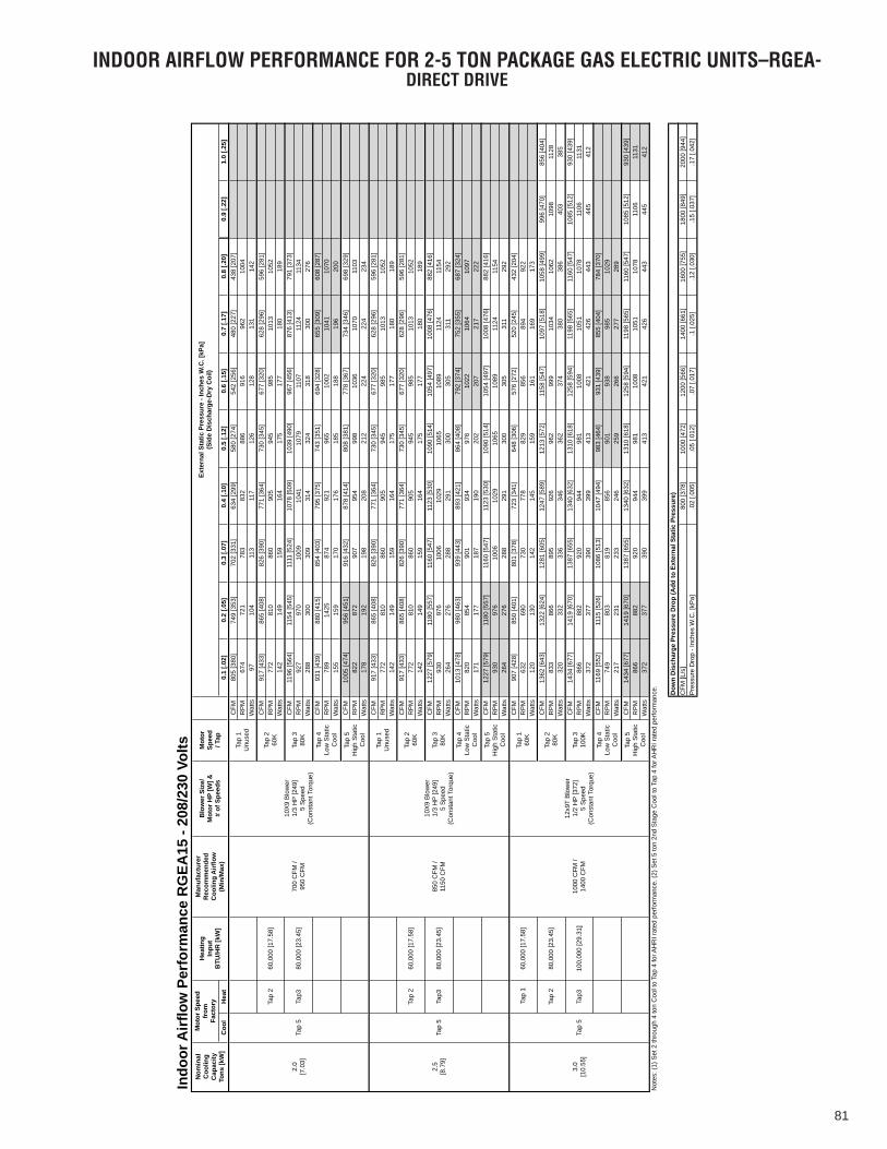
81
INDOOR AIRFLOW PERFORMANCE FOR 2-5 TON PACKAGE GAS ELECTRIC UNITS–RGEA-DIRECT DRIVE
Coo
lH
eat
0.1
[.02]
0.2
[.05]
0.3
[.07]
0.4
[.10]
0.5
[.12]
0.6
[.15]
0.7
[.17]
0.8
[.20]
0.9
[.22]
1.0
[.25]
CFM
805
[380
]74
9 [3
53]
702
[331
]63
4 [2
99]
580
[274
]54
2 [2
56]
480
[227
]43
8 [2
07]
RP
M67
472
178
383
288
691
696
210
04W
atts
9710
411
311
712
612
813
114
2C
FM91
7 [4
33]
865
[408
]82
6 [3
90]
771
[364
]73
0 [3
45]
677
[320
]62
8 [2
96]
596
[281
]R
PM
772
810
860
905
945
985
1013
1052
Wat
ts14
214
915
916
417
517
718
018
9C
FM11
96 [5
64]
1154
[545
]11
11 [5
24]
1078
[509
]10
39 [4
90]
967
[456
]87
6 [4
13]
791
[373
]R
PM
927
970
1009
1041
1079
1107
1124
1134
Wat
ts28
830
030
931
432
431
830
027
6C
FM93
1 [4
39]
880
[415
]85
4 [4
03]
795
[375
]74
3 [3
51]
694
[328
]65
5 [3
09]
608
[287
]R
PM
789
1425
874
921
965
1002
1041
1070
Wat
ts15
515
917
017
618
518
819
620
0C
FM10
05 [4
74]
956
[451
]91
6 [4
32]
878
[414
]80
8 [3
81]
778
[367
]73
4 [3
46]
698
[329
]R
PM
822
872
907
954
998
1036
1070
1103
Wat
ts17
819
219
820
821
222
422
423
4C
FM91
7 [4
33]
865
[408
]82
6 [3
90]
771
[364
]73
0 [3
45]
677
[320
]62
8 [2
96]
596
[281
]R
PM
772
810
860
905
945
985
1013
1052
Wat
ts14
214
915
916
417
517
718
018
9C
FM91
7 [4
33]
865
[408
]82
6 [3
90]
771
[364
]73
0 [3
45]
677
[320
]62
8 [2
96]
596
[281
]R
PM
772
810
860
905
945
985
1013
1052
Wat
ts14
214
915
916
417
517
718
018
9C
FM12
27 [5
79]
1180
[557
]11
60 [5
47]
1123
[530
]10
90 [5
14]
1054
[497
]10
08 [4
76]
882
[416
]R
PM
930
976
1006
1029
1065
1089
1124
1154
Wat
ts26
427
628
829
130
030
531
129
2C
FM10
13 [4
78]
980
[463
]93
9 [4
43]
893
[421
]86
4 [4
08]
792
[374
]75
2 [3
55]
687
[324
]R
PM
820
854
901
934
976
1022
1064
1097
Wat
ts17
117
718
719
020
220
721
722
2C
FM12
27 [5
79]
1180
[557
]11
60 [5
47]
1123
[530
]10
90 [5
14]
1054
[497
]10
08 [4
76]
882
[416
]R
PM
930
976
1006
1029
1065
1089
1124
1154
Wat
ts26
427
628
829
130
030
531
129
2C
FM90
7 [4
28]
850
[401
]80
1 [3
78]
723
[341
]64
8 [3
06]
576
[272
]52
0 [2
45]
432
[204
]R
PM
632
690
730
778
829
856
894
922
Wat
ts12
013
014
214
515
916
116
917
3C
FM13
62 [6
43]
1322
[624
]12
81 [6
05]
1247
[589
]12
13 [5
72]
1158
[547
]10
97 [5
18]
1058
[499
]99
6 [4
70]
856
[404
]R
PM
833
866
895
926
962
999
1034
1062
1098
1128
Wat
ts32
033
233
634
636
237
438
038
640
338
5C
FM14
34 [6
77]
1419
[670
]13
87 [6
55]
1340
[632
]13
10 [6
18]
1258
[594
]11
98 [5
65]
1160
[547
]10
85 [5
12]
930
[439
]R
PM
866
882
920
944
981
1008
1051
1078
1106
1131
Wat
ts37
237
739
039
941
342
142
644
344
541
2C
FM11
69 [5
52]
1115
[526
]10
86 [5
13]
1047
[494
]98
3 [4
64]
931
[439
]85
5 [4
04]
784
[370
]R
PM
749
803
819
856
901
938
985
1029
Wat
ts21
723
123
324
625
926
627
728
9C
FM14
34 [6
77]
1419
[670
]13
87 [6
55]
1340
[632
]13
10 [6
18]
1258
[594
]11
98 [5
65]
1160
[547
]10
85 [5
12]
930
[439
]R
PM
866
882
920
944
981
1008
1051
1078
1106
1131
Wat
ts37
237
739
039
941
342
142
644
344
541
2N
otes
: (1)
Set
2 th
roug
h 4
ton
Coo
l to
Tap
4 fo
r AH
RI r
ated
per
form
ance
. (2)
Set
5 to
n 2n
d S
tage
Coo
l to
Tap
4 fo
r AH
RI r
ated
per
form
ance
.
800
[378
]10
00 [4
72]
1200
[566
]14
00 [6
61]
1600
[755
]18
00 [8
49]
2000
[944
].0
2 [.0
05]
.05
[.012
].0
7 [.0
17]
.1 [.
025]
.12
[.030
].1
5 [.0
37]
.17
[.042
]
Indo
or A
irflo
w P
erfo
rman
ce R
GEA
15 -
208/
230
Volts
Nom
inal
Coo
ling
Cap
acity
Tons
[kW
]
Mot
or S
peed
from
Fact
ory
Hea
ting
Inpu
tB
TU/H
R [k
W]
Man
ufac
ture
rR
ecom
men
ded
Coo
ling
Airf
low
(Min
/Max
)
Blo
wer
Siz
e/M
otor
HP
[W] &
# of
Spe
eds
Mot
or
Spee
d/ T
ap
2.0
[7.0
3]Ta
p 5
700
CFM
/ 95
0 C
FM
Exte
rnal
Sta
tic P
ress
ure
- Inc
hes
W.C
. [kP
a](S
ide
Dis
char
ge-D
ry C
oil)
Tap
260
,000
[17.
58]
Tap
260
K
10X
9 B
low
er1/
3 H
P [2
49]
5 S
peed
(Con
stan
t Tor
que)
Tap
1U
nuse
d
Tap3
80,0
00 [2
3.45
]Ta
p 3
80K
Tap
4Lo
w S
tatic
C
ool
2.5
[8.7
9]Ta
p 5
850
CFM
/ 11
50 C
FM
10X
9 B
low
er1/
3 H
P [2
49]
5 S
peed
(Con
stan
t Tor
que)
Tap
1U
nuse
d
Tap
5H
igh
Sta
tic
Coo
l
Tap
260
,000
[17.
58]
Tap
260
K
Tap
4Lo
w S
tatic
C
ool
Tap3
80,0
00 [2
3.45
]Ta
p 3
80K
3.0
[10.
55]
Tap
5
Tap
160
,000
[17.
58]
1000
CFM
/ 14
00 C
FM
12x9
T B
low
er1/
2 H
P [3
72]
5 S
peed
(Con
stan
t Tor
que)
Tap
160
K
Tap
5H
igh
Sta
tic
Coo
l
Tap
280
,000
[23.
45]
Tap
280
K
Tap
4Lo
w S
tatic
C
ool
Tap3
100,
000
[29.
31]
Tap
310
0K
Tap
5H
igh
Sta
tic
Coo
l
Dow
n D
isch
arge
Pre
ssur
e D
rop
(Add
to E
xter
nal S
tatic
Pre
ssur
e)C
FM [L
/s]
Pre
ssur
e D
rop
- Inc
hes
W.C
. [kP
a]
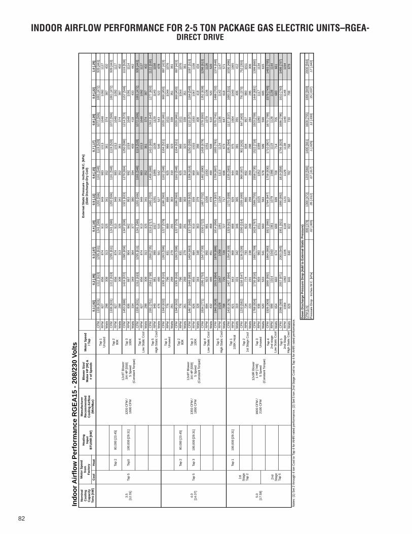
82
INDOOR AIRFLOW PERFORMANCE FOR 2-5 TON PACKAGE GAS ELECTRIC UNITS–RGEA-DIRECT DRIVE
Coo
lH
eat
0.1
[.02]
0.2
[.05]
0.3
[.07]
0.4
[.10]
0.5
[.12]
0.6
[.15]
0.7
[.17]
0.8
[.20]
0.9
[.22]
1.0
[.25]
CFM
1336
[631
]13
12 [6
19]
1295
[611
]12
41 [5
86]
1200
[566
]11
61 [5
48]
1119
[528
]10
72 [5
06]
1001
[472
]93
9 [4
43]
RP
M82
785
687
491
394
998
310
1310
4810
9211
27W
atts
298
308
313
325
341
352
361
374
387
402
CFM
1336
[631
]13
12 [6
19]
1295
[611
]12
41 [5
86]
1200
[566
]11
61 [5
48]
1119
[528
]10
72 [5
06]
1001
[472
]93
9 [4
43]
RP
M82
785
687
491
394
998
310
1310
4810
9211
27W
atts
298
308
313
325
341
352
361
374
387
402
CFM
1453
[686
]14
24 [6
72]
1395
[658
]13
47 [6
36]
1321
[623
]12
79 [6
04]
1250
[590
]12
14 [5
73]
1157
[546
]11
19 [5
28]
RP
M83
686
790
494
295
399
210
1910
4810
9111
14W
atts
334
349
364
377
380
394
409
418
433
442
CFM
1336
[631
]13
12 [6
19]
1295
[611
]12
41 [5
86]
1200
[566
]11
61 [5
48]
1119
[528
]10
72 [5
06]
1001
[472
]93
9 [4
43]
RP
M82
785
687
491
394
998
310
1310
4810
9211
27W
atts
298
308
313
325
341
352
361
374
387
402
CFM
1591
[751
]15
63 [7
38]
1558
[735
]15
19 [7
17]
1490
[703
]14
58 [6
88]
1410
[665
]13
63 [6
43]
1277
[603
]11
22 [5
30]
RP
M94
998
199
910
2710
5110
8611
0911
2911
4011
58W
atts
476
490
501
515
527
542
546
543
522
478
CFM
1340
[632
]13
05 [6
16]
1263
[596
]12
27 [5
79]
1186
[560
]11
62 [5
48]
1104
[521
]10
20 [4
81]
960
[453
]89
7 [4
23]
RP
M77
679
683
186
989
892
596
610
1110
4410
76W
atts
261
268
279
291
303
310
323
339
351
361
CFM
1340
[632
]13
05 [6
16]
1263
[596
]12
27 [5
79]
1186
[560
]11
62 [5
48]
1104
[521
]10
20 [4
81]
960
[453
]89
7 [4
23]
RP
M77
679
683
186
989
892
596
610
1110
4410
76W
atts
261
268
279
291
303
310
323
339
351
361
CFM
1467
[692
]14
48 [6
83]
1404
[663
]13
73 [6
48]
1339
[632
]13
06 [6
16]
1250
[590
]12
10 [5
71]
1164
[549
]10
87 [5
13]
RP
M82
685
588
491
093
996
910
0310
3010
6711
08W
atts
328
344
348
363
379
387
398
408
418
434
CFM
1634
[771
]15
95 [7
53]
1547
[730
]15
30 [7
22]
1487
[702
]14
62 [6
90]
1438
[679
]13
78 [6
50]
1352
[638
]12
98 [6
13]
RP
M89
492
395
098
110
0010
3010
5110
7911
0611
26W
atts
432
446
451
468
479
490
508
510
520
520
CFM
1941
[916
]19
15 [9
04]
1878
[886
]18
14 [8
56]
1773
[837
]17
09 [8
07]
1655
[781
]15
70 [7
41]
1488
[702
]13
74 [6
48]
RP
M10
2810
4710
6810
9111
0411
1311
2411
3611
4211
47W
atts
708
725
729
727
717
696
673
647
618
571
CFM
1433
[676
]14
07 [6
64]
1354
[639
]13
29 [6
27]
1270
[599
]12
35 [5
83]
1195
[564
]11
37 [5
37]
1083
[511
]10
30 [4
86]
RP
M82
184
386
888
892
994
497
510
0410
4010
65W
atts
319
331
342
346
365
368
381
391
406
412
CFM
1233
[582
]11
58 [5
47]
1136
[536
]10
90 [5
14]
1039
[490
]96
9 [4
57]
902
[426
]84
7 [4
00]
791
[373
]75
2 [3
55]
RP
M73
477
479
382
286
089
293
495
798
310
11W
atts
223
231
238
248
259
269
288
284
295
306
CFM
1768
[834
]17
30 [8
16]
1693
[799
]16
26 [7
67]
1599
[755
]15
58 [7
35]
1522
[718
]15
03 [7
09]
1444
[681
]13
99 [6
60]
RP
M93
895
998
310
1110
2510
5210
8910
9011
1711
34W
atts
520
533
541
560
563
578
599
599
605
615
CFM
1926
[909
]18
90 [8
92]
1864
[880
]18
22 [8
60]
1794
[847
]17
58 [8
30]
1710
[807
]16
70 [7
88]
1579
[745
]14
93 [7
05]
RP
M99
910
1410
4010
6110
7910
9611
1911
2811
3811
44W
atts
654
660
674
688
699
708
714
705
683
661
CFM
2096
[989
]20
57 [9
71]
2003
[945
]19
51 [9
21]
1890
[892
]18
19 [8
58]
1756
[829
]16
86 [7
96]
1610
[760
]14
98 [7
07]
RP
M10
6910
9211
0611
1611
2111
2911
3811
4011
4811
54W
atts
829
846
840
822
807
782
768
730
708
679
Not
es: (
1) S
et 2
thro
ugh
4 to
n C
ool t
o Ta
p 4
for A
HR
I rat
ed p
erfo
rman
ce. (
2) S
et 5
ton
2nd
Sta
ge C
ool t
o Ta
p 4
for A
HR
I rat
ed p
erfo
rman
ce.
800
[378
]10
00 [4
72]
1200
[566
]14
00 [6
61]
1600
[755
]18
00 [8
49]
2000
[944
].0
2 [.0
05]
.05
[.012
].0
7 [.0
17]
.1 [.
025]
.12
[.030
].1
5 [.0
37]
.17
[.042
]
Indo
or A
irflo
w P
erfo
rman
ce R
GEA
15 -
208/
230
Volts Mot
or S
peed
/ Tap
Exte
rnal
Sta
tic P
ress
ure
- Inc
hes
W.C
. [kP
a](S
ide
Dis
char
ge-D
ry C
oil)
Nom
inal
Coo
ling
Cap
acity
Tons
[kW
]
Mot
or S
peed
from
Fact
ory
Hea
ting
Inpu
tB
TU/H
R [k
W]
Man
ufac
ture
rR
ecom
men
ded
Coo
ling
Airf
low
(Min
/Max
)
Blo
wer
Siz
e/M
otor
HP
[W] &
# of
Spe
eds
Tap
280
,000
[23.
45]
Tap
280
K
1200
CFM
/ 16
00 C
FM
12x9
T B
low
er3/
4 H
P [5
59]
5 S
peed
(Con
stan
t Tor
que)
Tap
1U
nuse
d
3.5
[12.
31]
Tap
5Ta
p310
0,00
0 [2
9.31
]Ta
p 3
100K
Tap
4Lo
w S
tatic
Coo
l
4.0
[14.
07]
Tap
5H
igh
Sta
tic C
ool
Tap
280
,000
[23.
45]
Tap
280
K
Tap
513
50 C
FM /
1850
CFM
Tap
4Lo
w S
tatic
Coo
l
Tap
310
0,00
0 [2
9.31
]Ta
p 3
100K
12x9
T B
low
er3/
4 H
P [5
59]
5 S
peed
(Con
stan
t Tor
que)
Tap
1U
nuse
d
5.0
[17.
59]
1st
Sta
ge
Tap
2
Tap
5H
igh
Sta
tic C
ool
Tap
21s
t Sta
ge C
ool
Tap
110
0,00
0 [2
9.31
]
1600
CFM
/ 21
00 C
FM
12x9
R B
low
er1
HP
[746
]5
Spe
ed(C
onst
ant T
orqu
e)
Tap
110
0K H
eat
2nd
Sta
ge
Tap
5
Tap
42n
d st
age
Low
Sta
tic C
ool
Tap
3U
nuse
d
Tap
52n
d S
tage
Hig
h S
tatic
Coo
l
Dow
n D
isch
arge
Pre
ssur
e D
rop
(Add
to E
xter
nal S
tatic
Pre
ssur
e)C
FM [L
/s]
Pre
ssur
e D
rop
- Inc
hes
W.C
. [kP
a]
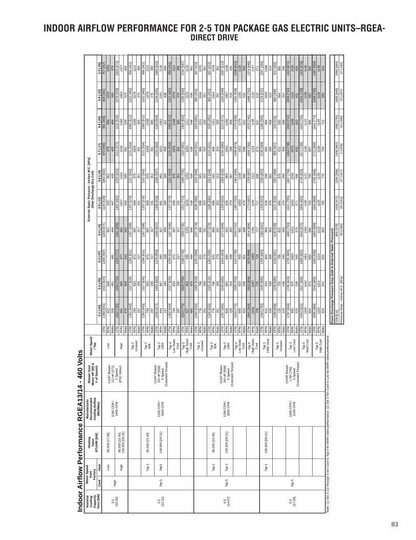
83
INDOOR AIRFLOW PERFORMANCE FOR 2-5 TON PACKAGE GAS ELECTRIC UNITS–RGEA-DIRECT DRIVE
Coo
lH
eat
0.1
[.02]
0.2
[.05]
0.3
[.07]
0.4
[.10]
0.5
[.12]
0.6
[.15]
0.7
[.17]
0.8
[.20]
0.9
[.22]
1.0
[.25]
CFM
1358
[641
]13
22 [6
24]
1266
[597
]12
09 [5
71]
1120
[529
]10
63 [5
02]
970
[458
]86
1 [4
06]
828
[391
]75
7 [3
57]
RP
M82
384
9`
901
932
953
979
999
1029
1055
Wat
ts50
549
148
146
444
743
942
240
439
337
8C
FM16
52 [7
80]
1596
[753
]15
40 [7
27]
1481
[699
]14
02 [6
62]
1320
[623
]12
12 [5
72]
1132
[534
]10
79 [5
09]
1004
[474
]R
PM
951
965
977
992
1007
1019
1036
1050
1063
1077
Wat
ts67
065
864
262
560
058
056
153
952
350
4C
FM13
62 [6
43]
1327
[626
]12
94 [6
11]
1267
[598
]12
07 [5
70]
1151
[543
]11
31 [5
34]
1085
[512
]10
22 [4
82]
956
[451
]R
PM
794
833
872
897
948
976
1005
1038
1078
1112
Wat
ts28
729
531
731
733
135
136
136
537
039
9C
FM13
62 [6
43]
1327
[626
]12
94 [6
11]
1267
[598
]12
07 [5
70]
1151
[543
]11
31 [5
34]
1085
[512
]10
22 [4
82]
956
[451
]R
PM
794
833
872
897
948
976
1005
1038
1078
1112
Wat
ts28
729
531
731
733
135
136
136
537
039
9C
FM14
35 [6
77]
1405
[663
]13
78 [6
50]
1349
[637
]13
09 [6
18]
1266
[597
]12
33 [5
82]
1193
[563
]11
34 [5
35]
1066
[503
]R
PM
844
867
892
927
961
991
1022
1052
1101
1130
Wat
ts33
734
035
836
839
038
940
941
143
844
6C
FM13
62 [6
43]
1327
[626
]12
94 [6
11]
1267
[598
]12
07 [5
70]
1151
[543
]11
31 [5
34]
1085
[512
]10
22 [4
82]
956
[451
]R
PM
794
833
872
897
948
976
1005
1038
1078
1112
Wat
ts28
729
531
731
733
135
136
136
537
039
9C
FM16
43 [7
75]
1609
[759
]15
80 [7
46]
1560
[736
]15
11 [7
13]
1494
[705
]14
43 [6
81]
1404
[663
]13
35 [6
30]
1244
[587
]R
PM
927
954
986
1001
1035
1052
1083
1111
1122
1133
Wat
ts46
147
549
050
651
852
853
554
853
050
2C
FM13
40 [6
32]
1305
[616
]12
63 [5
96]
1227
[579
]11
86 [5
60]
1162
[548
]11
04 [5
21]
1020
[481
]96
0 [4
53]
897
[423
]R
PM
776
796
831
869
898
925
966
1011
1044
1076
Wat
ts26
126
827
929
130
331
032
333
935
136
1C
FM13
40 [6
32]
1305
[616
]12
63 [5
96]
1227
[579
]11
86 [5
60]
1162
[548
]11
04 [5
21]
1020
[481
]96
0 [4
53]
897
[423
]R
PM
776
796
831
869
898
925
966
1011
1044
1076
Wat
ts26
126
827
929
130
331
032
333
935
136
1C
FM14
67 [6
92]
1448
[683
]14
04 [6
63]
1373
[648
]13
39 [6
32]
1306
[616
]12
50 [5
90]
1210
[571
]11
64 [5
49]
1087
[513
]R
PM
826
855
884
910
939
969
1003
1030
1067
1108
Wat
ts32
834
434
836
337
938
739
840
841
843
4C
FM16
34 [7
71]
1595
[753
]15
47 [7
30]
1530
[722
]14
87 [7
02]
1462
[690
]14
38 [6
79]
1378
[650
]13
52 [6
38]
1298
[613
]R
PM
894
923
950
981
1000
1030
1051
1079
1106
1126
Wat
ts43
244
645
146
847
949
050
851
052
052
0C
FM19
41 [9
16]
1915
[904
]18
78 [8
86]
1814
[856
]17
73 [8
37]
1709
[807
]16
55 [7
81]
1570
[741
]14
88 [7
02]
1374
[648
]R
PM
1028
1047
1068
1091
1104
1113
1124
1136
1142
1147
Wat
ts70
872
572
972
771
769
667
364
761
857
1C
FM14
84 [7
00]
1440
[680
]14
05 [6
63]
1360
[642
]13
19 [6
22]
1280
[604
]12
38 [5
84]
1186
[560
]11
28 [5
32]
1047
[494
]R
PM
812
841
863
889
918
938
965
994
1026
1066
Wat
ts33
033
835
535
437
938
139
540
842
341
9C
FM12
89 [6
08]
1239
[585
]11
89 [5
61]
1140
[538
]11
01 [5
20]
1052
[496
]96
9 [4
57]
918
[433
]86
0 [4
06]
812
[383
]R
PM
726
755
786
815
846
876
912
935
964
986
Wat
ts23
324
824
925
927
529
230
930
832
133
0C
FM17
87 [8
43]
1746
[824
]17
05 [8
05]
1680
[793
]16
21 [7
65]
1607
[758
]15
64 [7
38]
1530
[722
]15
05 [7
10]
1424
[672
]R
PM
950
970
1000
1012
1042
1055
1079
1108
1113
1130
Wat
ts52
553
854
557
957
159
661
561
063
162
6C
FM19
54 [9
22]
1927
[909
]18
89 [8
92]
1843
[870
]18
08 [8
53]
1738
[820
]16
71 [7
89]
1620
[765
]15
43 [7
28]
1433
[676
]R
PM
1030
1042
1061
1082
1100
1121
1130
1133
1138
1146
Wat
ts66
467
368
369
670
470
069
768
466
763
5C
FM20
95 [9
89]
2045
[965
]19
83 [9
36]
1905
[899
]18
40 [8
68]
1792
[846
]17
12 [8
08]
1641
[774
]15
58 [7
35]
1397
[659
]R
PM
1103
1114
1114
1123
1125
1130
1139
1140
1144
1148
Wat
ts82
984
183
280
378
577
074
971
068
563
3N
ote:
(1) S
et 3
-1/2
thro
ugh
5 to
n C
ool t
o Ta
p 4
for A
HR
I rat
ed p
erfo
rman
ce. (
2) S
et 3
Ton
Coo
l to
Low
for A
HR
I rat
ed p
erfo
rman
ce.
800
[378
]10
00 [4
72]
1200
[566
]14
00 [6
61]
1600
[755
]18
00 [8
49]
2000
[944
].0
2 [.0
05]
.05
[.012
].0
7 [.0
17]
.1 [.
025]
.12
[.030
].1
5 [.0
37]
.17
[.042
]
Indo
or A
irflo
w P
erfo
rman
ce R
GEA
13/1
4 - 4
60 V
olts
Man
ufac
ture
rR
ecom
men
ded
Coo
ling
Airf
low
(Min
/Max
)
Blo
wer
Siz
e/M
otor
HP
[W] &
# of
Spe
eds
Mot
or S
peed
/ Tap
Exte
rnal
Sta
tic P
ress
ure
- Inc
hes
W.C
. [kP
a](S
ide
Dis
char
ge-D
ry C
oil)
Nom
inal
Coo
ling
Cap
acity
Tons
[kW
]
Mot
or S
peed
from
Fact
ory
Hea
ting
Inpu
tB
TU/H
R [k
W]
60,0
00 [1
7.58
]10
00 C
FM /
1400
CFM
12x9
T B
low
er1/
2 H
P [3
72]
2 S
peed
(PS
C M
otor
)
Low
3.0
[10.
55]
Hig
h
Low
Hig
h80
,000
[23.
45]
100,
000
[29.
31]
Hig
h
Tap
1U
nuse
d
Tap
280
,000
[23.
45]
Tap
280
K
3.5
[12.
31]
Tap
512
00 C
FM /
1600
CFM
12x9
T B
low
er3/
4 H
P [5
59]
5 S
peed
(Con
stan
t Tor
que)
Tap3
100,
000
[29.
31]
Tap
310
0K
Tap
4Lo
w S
tatic
C
ool
Tap
5H
igh
Sta
tic
Coo
l
80,0
00 [2
3.45
]Ta
p 2
80K
Tap
310
0,00
0 [2
9.31
]Ta
p 3
100K
1350
CFM
/ 18
50 C
FM
12x9
T B
low
er3/
4 H
P [5
59]
5 S
peed
(Con
stan
t Tor
que)
Tap
1U
nuse
d
Tap
2
4.0
[14.
07]
Tap
5
Tap
4Lo
w S
tatic
C
ool
Tap
5H
igh
Sta
tic
Coo
l
Tap
110
0,00
0 [2
9.31
]
Tap
2U
nuse
d
Tap
3Lo
w C
ool
1600
CFM
/ 21
00 C
FM
12x9
R B
low
er1
HP
[746
]5
Spe
ed(C
onst
ant T
orqu
e)
Tap
110
0K H
eat
5.0
[17.
59]
Tap
5
Tap
4M
ed C
ool
Tap
5H
igh
Coo
l
Pre
ssur
e D
rop
- Inc
hes
W.C
. [kP
a]
Dow
n D
isch
arge
Pre
ssur
e D
rop
(Add
to E
xter
nal S
tatic
Pre
ssur
e)C
FM [L
/s]

84
INDOOR AIRFLOW PERFORMANCE FOR 2-5 TON PACKAGE GAS ELECTRIC UNITS–RGEA-DIRECT DRIVE
Coo
lH
eat
0.1
[.02]
0.2
[.05]
0.3
[.07]
0.4
[.10]
0.5
[.12]
0.6
[.15]
0.7
[.17]
0.8
[.20]
0.9
[.22]
1.0
[.25]
CFM
912
[430
]87
1 [4
11]
808
[381
]73
4 [3
46]
655
[309
]57
1 [2
69]
520
[245
]44
7 [2
11]
RP
M63
466
472
276
981
185
088
190
6W
atts
111
116
131
137
149
151
162
165
CFM
1362
[643
]13
27 [6
26]
1294
[611
]12
67 [5
98]
1207
[570
]11
51 [5
43]
1131
[534
]10
85 [5
12]
1022
[482
]95
6 [4
51]
RP
M79
483
387
289
794
897
610
0510
3810
7811
12W
atts
287
295
317
317
331
351
361
365
370
399
CFM
1435
[677
]14
05 [6
63]
1378
[650
]13
49 [6
37]
1309
[618
]12
66 [5
97]
1233
[582
]11
93 [5
63]
1134
[535
]10
66 [5
03]
RP
M84
486
789
292
796
199
110
2210
5211
0111
30W
atts
337
340
358
368
390
389
409
411
438
446
CFM
1163
[549
]11
44 [5
40]
1086
[513
]10
73 [5
06]
987
[466
]92
7 [4
37]
870
[411
]81
9 [3
87]
RP
M74
976
181
083
688
792
096
410
05W
atts
202
205
217
230
248
248
266
271
CFM
1435
[677
]14
05 [6
63]
1378
[650
]13
49 [6
37]
1309
[618
]12
66 [5
97]
1233
[582
]11
93 [5
63]
1134
[535
]10
66 [5
03]
RP
M84
486
789
292
796
199
110
2210
5211
0111
30W
atts
337
340
358
368
390
389
409
411
438
446
CFM
1362
[643
]13
27 [6
26]
1294
[611
]12
67 [5
98]
1207
[570
]11
51 [5
43]
1131
[534
]10
85 [5
12]
1022
[482
]95
6 [4
51]
RP
M79
483
387
289
794
897
610
0510
3810
7811
12W
atts
287
295
317
317
331
351
361
365
370
399
CFM
1362
[643
]13
27 [6
26]
1294
[611
]12
67 [5
98]
1207
[570
]11
51 [5
43]
1131
[534
]10
85 [5
12]
1022
[482
]95
6 [4
51]
RP
M79
483
387
289
794
897
610
0510
3810
7811
12W
atts
287
295
317
317
331
351
361
365
370
399
CFM
1435
[677
]14
05 [6
63]
1378
[650
]13
49 [6
37]
1309
[618
]12
66 [5
97]
1233
[582
]11
93 [5
63]
1134
[535
]10
66 [5
03]
RP
M84
486
789
292
796
199
110
2210
5211
0111
30W
atts
337
340
358
368
390
389
409
411
438
446
CFM
1362
[643
]13
27 [6
26]
1294
[611
]12
67 [5
98]
1207
[570
]11
51 [5
43]
1131
[534
]10
85 [5
12]
1022
[482
]95
6 [4
51]
RP
M79
483
387
289
794
897
610
0510
3810
7811
12W
atts
287
295
317
317
331
351
361
365
370
399
CFM
1643
[775
]16
09 [7
59]
1580
[746
]15
60 [7
36]
1511
[713
]14
94 [7
05]
1443
[681
]14
04 [6
63]
1335
[630
]12
44 [5
87]
RP
M92
795
498
610
0110
3510
5210
8311
1111
2211
33W
atts
461
475
490
506
518
528
535
548
530
502
CFM
1340
[632
]13
05 [6
16]
1263
[596
]12
27 [5
79]
1186
[560
]11
62 [5
48]
1104
[521
]10
20 [4
81]
960
[453
]89
7 [4
23]
RP
M77
679
683
186
989
892
596
610
1110
4410
76W
atts
261
268
279
291
303
310
323
339
351
361
CFM
1340
[632
]13
05 [6
16]
1263
[596
]12
27 [5
79]
1186
[560
]11
62 [5
48]
1104
[521
]10
20 [4
81]
960
[453
]89
7 [4
23]
RP
M77
679
683
186
989
892
596
610
1110
4410
76W
atts
261
268
279
291
303
310
323
339
351
361
CFM
1467
[692
]14
48 [6
83]
1404
[663
]13
73 [6
48]
1339
[632
]13
06 [6
16]
1250
[590
]12
10 [5
71]
1164
[549
]10
87 [5
13]
RP
M82
685
588
491
093
996
910
0310
3010
6711
08W
atts
328
344
348
363
379
387
398
408
418
434
CFM
1634
[771
]15
95 [7
53]
1547
[730
]15
30 [7
22]
1487
[702
]14
62 [6
90]
1438
[679
]13
78 [6
50]
1352
[638
]12
98 [6
13]
RP
M89
492
395
098
110
0010
3010
5110
7911
0611
26W
atts
432
446
451
468
479
490
508
510
520
520
CFM
1941
[916
]19
15 [9
04]
1878
[886
]18
14 [8
56]
1773
[837
]17
09 [8
07]
1655
[781
]15
70 [7
41]
1488
[702
]13
74 [6
48]
RP
M10
2810
4710
6810
9111
0411
1311
2411
3611
4211
47W
atts
708
725
729
727
717
696
673
647
618
571
CFM
1484
[700
]14
40 [6
80]
1405
[663
]13
60 [6
42]
1319
[622
]12
80 [6
04]
1238
[584
]11
86 [5
60]
1128
[532
]10
47 [4
94]
RP
M81
284
186
388
991
893
896
599
410
2610
66W
atts
330
338
355
354
379
381
395
408
423
419
CFM
1289
[608
]12
39 [5
85]
1189
[561
]11
40 [5
38]
1101
[520
]10
52 [4
96]
969
[457
]91
8 [4
33]
860
[406
]81
2 [3
83]
RP
M72
675
578
681
584
687
691
293
596
498
6W
atts
233
248
249
259
275
292
309
308
321
330
CFM
1787
[843
]17
46 [8
24]
1705
[805
]16
80 [7
93]
1621
[765
]16
07 [7
58]
1564
[738
]15
30 [7
22]
1505
[710
]14
24 [6
72]
RP
M95
097
010
0010
1210
4210
5510
7911
0811
1311
30W
atts
525
538
545
579
571
596
615
610
631
626
CFM
1954
[922
]19
27 [9
09]
1889
[892
]18
43 [8
70]
1808
[853
]17
38 [8
20]
1671
[789
]16
20 [7
65]
1543
[728
]14
33 [6
76]
RP
M10
3010
4210
6110
8211
0011
2111
3011
3311
3811
46W
atts
664
673
683
696
704
700
697
684
667
635
CFM
2095
[989
]20
45 [9
65]
1983
[936
]19
05 [8
99]
1840
[868
]17
92 [8
46]
1712
[808
]16
41 [7
74]
1558
[735
]13
97 [6
59]
RP
M11
0311
1411
1411
2311
2511
3011
3911
4011
4411
48W
atts
829
841
832
803
785
770
749
710
685
633
Not
es: (
1) S
et 2
thro
ugh
4 to
n C
ool t
o Ta
p 4
for A
HR
I rat
ed p
erfo
rman
ce. (
2) S
et 5
ton
2nd
Sta
ge C
ool t
o Ta
p 4
for A
HR
I rat
ed p
erfo
rman
ce.
800
[378
]10
00 [4
72]
1200
[566
]14
00 [6
61]
1600
[755
]18
00 [8
49]
2000
[944
].0
2 [.0
05]
.05
[.012
].0
7 [.0
17]
.1 [.
025]
.12
[.030
].1
5 [.0
37]
.17
[.042
]
Indo
or A
irflo
w P
erfo
rman
ce R
GEA
15 -
460
Volts
Man
ufac
ture
rR
ecom
men
ded
Coo
ling
Airf
low
(Min
/Max
)
Blo
wer
Siz
e/M
otor
HP
[W] &
# of
Spe
eds
Mot
or S
peed
/ Tap
Exte
rnal
Sta
tic P
ress
ure
- Inc
hes
W.C
. [kP
a](S
ide
Dis
char
ge-D
ry C
oil)
Nom
inal
Coo
ling
Cap
acity
Tons
[kW
]
Mot
or S
peed
from
Fact
ory
Hea
ting
Inpu
tB
TU/H
R [k
W]
60,0
00 [1
7.58
]
1000
CFM
/ 14
00 C
FM
12x9
T B
low
er1/
2 H
P [3
72]
5 S
peed
(Con
stan
t Tor
que)
Tap
160
K
3.0
[10.
55]
Tap
5
Tap
1
Tap
280
,000
[23.
45]
Tap
280
K
Tap3
100,
000
[29.
31]
Tap
310
0K
Tap
4Lo
w S
tatic
C
ool
Tap
5H
igh
Sta
tic
Coo
l
Tap
1U
nuse
d
Tap
280
,000
[23.
45]
Tap
280
K
3.5
[12.
31]
Tap
512
00 C
FM /
1600
CFM
12x9
T B
low
er3/
4 H
P [5
59]
5 S
peed
(Con
stan
t Tor
que)
Tap3
100,
000
[29.
31]
Tap
310
0K
Tap
4Lo
w S
tatic
C
ool
Tap
5H
igh
Sta
tic
Coo
l
Tap
5
Tap
280
,000
[23.
45]
Tap
34.
0[1
4.07
]10
0,00
0 [2
9.31
]Ta
p 3
100K
1350
CFM
/ 18
50 C
FM
12x9
T B
low
er3/
4 H
P [5
59]
5 S
peed
(Con
stan
t Tor
que)
Tap
1U
nuse
d
Tap
280
K
Tap
4Lo
w S
tatic
C
ool
Tap
5H
igh
Sta
tic
Coo
l
5.0
[17.
59]
1st
Sta
ge
Tap
2
Tap
110
0,00
0 [2
9.31
]
1600
CFM
/ 21
00 C
FM
12x9
R B
low
er1
HP
[746
]5
Spe
ed(C
onst
ant T
orqu
e)
Tap
110
0K H
eat
Tap
21s
t Sta
ge C
ool
Dow
n D
isch
arge
Pre
ssur
e D
rop
(Add
to E
xter
nal S
tatic
Pre
ssur
e)C
FM [L
/s]
Pre
ssur
e D
rop
- Inc
hes
W.C
. [kP
a]
Tap
3U
nuse
d
2nd
Sta
ge
Tap
5
Tap
42n
d st
age
Low
Sta
tic
Coo
lTa
p 5
2nd
Sta
geH
igh
Sta
tic
Coo
l

85
INDOOR AIRFLOW PERFORMANCE FOR 2-5 TON PACKAGE GAS ELECTRIC UNITS–RGEA-DIRECT DRIVE
IND
OO
R A
IRFL
OW
PER
FORM
AN
CE -
208
& 2
30 V
OLT
S
0.1
[.02
]0.
2 [.
05]
0.3
[.07
]0.
4 [.
10]
0.5
[.12
]0.
6 [.
15]
0.7
[.17
]0.
8 [.
20]
0.9
[.22
]1.
0 [.
25]
CFM
[l/s
]76
6 [3
62]
773
[365
]77
1 [3
64]
770
[363
]76
8 [3
62]
757
[357
]75
1 [3
54]
742
[350
]72
6 [3
43]
715
[337
]RP
M64
974
682
989
794
610
0010
4610
8811
3311
70W
atts
8310
713
015
216
918
820
622
224
025
5CF
M [l
/s]
891
[421
]90
2 [4
26]
910
[429
]90
6 [4
28]
912
[430
]90
6 [4
28]
903
[426
]89
1 [4
21]
876
[413
]86
8 [4
10]
RPM
747
831
895
957
1017
1068
1111
1151
1186
1223
Wat
ts12
315
217
620
022
524
726
828
830
232
1CF
M [l
/s]
1189
[561
]11
98 [5
65]
1203
[568
]12
10 [5
71]
1212
[572
]12
08 [5
70]
1193
[563
]11
94 [5
64]
1146
[541
]10
72 [5
06]
RPM
894
964
1008
1084
1142
1187
1234
1285
1301
1310
Wat
ts23
627
329
934
437
841
144
147
747
544
6CF
M [l
/s]
891
[421
]90
2 [4
26]
910
[429
]90
6 [4
28]
912
[430
]90
6 [4
28]
903
[426
]89
1 [4
21]
876
[413
]86
8 [4
10]
RPM
747
831
895
957
1017
1068
1111
1151
1186
1223
Wat
ts12
315
217
620
022
524
726
828
830
232
1CF
M [l
/s]
766
[362
]77
3 [3
65]
771
[364
]77
0 [3
63]
768
[362
]75
7 [3
57]
751
[354
]74
2 [3
50]
726
[343
]71
5 [3
37]
RPM
649
746
829
897
946
1000
1046
1088
1133
1170
Wat
ts83
107
130
152
169
188
206
222
240
255
CFM
[l/s
]95
9 [4
53]
973
[459
]97
8 [4
62]
981
[463
]98
5 [4
65]
974
[460
]96
6 [4
56]
962
[454
]95
2 [4
49]
949
[448
]RP
M77
285
592
299
010
5211
0011
4211
8412
1912
56W
atts
141
172
200
231
259
282
304
326
343
363
CFM
[l/s
]11
89 [5
61]
1198
[565
]12
03 [5
68]
1210
[571
]12
12 [5
72]
1208
[570
]11
93 [5
63]
1194
[564
]11
46 [5
41]
1072
[506
]RP
M89
496
410
0810
8411
4211
8712
3412
8513
0113
10W
atts
236
273
299
344
378
411
441
477
475
446
CFM
[l/s
]95
9 [4
53]
973
[459
]97
8 [4
62]
981
[463
]98
5 [4
65]
974
[460
]96
6 [4
56]
962
[454
]95
2 [4
49]
949
[448
]RP
M77
285
592
299
010
5211
0011
4211
8412
1912
56W
atts
141
172
200
231
259
282
304
326
343
363
CFM
[l/s
]76
6 [3
62]
773
[365
]77
1 [3
64]
770
[363
]76
8 [3
62]
757
[357
]75
1 [3
54]
742
[350
]72
6 [3
43]
715
[337
]RP
M64
974
682
989
794
610
0010
4610
8811
3311
70W
atts
8310
713
015
216
918
820
622
224
025
5CF
M [l
/s]
1189
[561
]11
99 [5
66]
1204
[568
]12
06 [5
69]
1210
[571
]12
02 [5
67]
1209
[571
]11
65 [5
50]
1125
[531
]10
61 [5
01]
RPM
908
964
1024
1094
1144
1195
1234
1269
1290
1307
Wat
ts24
727
831
135
438
542
144
845
745
444
6CF
M [l
/s]
1186
[560
]11
91 [5
62]
1191
[562
]11
99 [5
66]
1192
[563
]11
82 [5
58]
1171
[553
]11
56 [5
46]
1123
[530
]10
45 [4
93]
RPM
904
974
1023
1077
1129
1174
1216
1263
1288
1292
Wat
ts23
527
129
632
635
437
940
043
042
541
3CF
M [l
/s]
1194
[564
]12
00 [5
66]
1200
[566
]12
08 [5
70]
1200
[566
]11
90 [5
62]
1179
[556
]11
65 [5
50]
1128
[532
]10
45 [4
93]
RPM
910
981
1027
1083
1134
1179
1219
1267
1291
1294
Wat
ts23
927
630
033
235
938
440
543
542
841
4CF
M [l
/s]
1186
[560
]11
91 [5
62]
1191
[562
]11
99 [5
66]
1192
[563
]11
82 [5
58]
1171
[553
]11
56 [5
46]
1123
[530
]10
45 [4
93]
RPM
904
974
1023
1077
1129
1174
1216
1263
1288
1292
Wat
ts23
527
129
632
635
437
940
043
042
541
3CF
M [l
/s]
1296
[612
]12
94 [6
11]
1299
[613
]12
99 [6
13]
1294
[611
]12
88 [6
08]
1275
[602
]12
26 [5
79]
1141
[538
]10
50 [4
96]
RPM
969
1035
1078
1133
1173
1220
1259
1295
1302
1301
Wat
ts29
233
035
739
041
144
446
748
144
942
3CF
M [l
/s]
1206
[569
]12
15 [5
73]
1219
[575
]12
16 [5
74]
1218
[575
]12
20 [5
76]
1216
[574
]12
15 [5
73]
1205
[569
]11
95 [5
64]
RPM
730
796
837
885
926
962
999
1038
1075
1112
Wat
ts19
923
826
129
231
734
236
839
742
745
7CF
M [l
/s]
1535
[724
]15
45 [7
29]
1551
[732
]15
54 [7
33]
1553
[733
]15
53 [7
33]
1551
[732
]15
48 [7
31]
1543
[728
]15
32 [7
23]
RPM
873
923
967
1005
1052
1096
1124
1149
1180
1200
Wat
ts37
141
645
649
053
757
860
763
466
668
7CF
M [l
/s]
1206
[569
]12
15 [5
73]
1219
[575
]12
16 [5
74]
1218
[575
]12
20 [5
76]
1216
[574
]12
15 [5
73]
1205
[569
]11
95 [5
64]
RPM
730
796
837
885
926
962
999
1038
1075
1112
Wat
ts19
923
826
129
231
734
236
839
742
745
7CF
M [l
/s]
1248
[589
]12
56 [5
93]
1262
[596
]12
61 [5
95]
1262
[596
]12
64 [5
97]
1261
[595
]12
61 [5
95]
1253
[591
]12
43 [5
87]
RPM
749
808
853
903
942
979
1014
1051
1086
1121
Wat
ts21
825
428
131
534
136
939
442
245
248
1CF
M [l
/s]
1837
[867
]18
50 [8
73]
1850
[873
]18
53 [8
75]
1854
[875
]18
47 [8
72]
1834
[866
]18
34 [8
66]
1824
[861
]18
18 [8
58]
RPM
997
1053
1094
1128
1164
1202
1225
1256
1283
1305
Wat
ts60
467
071
976
281
086
087
288
992
795
6
[ ]
Des
igna
tes
Met
ric
Conv
ersi
ons
Exte
rnal
Sta
tic
Pres
sure
- In
ches
W.C
. [kP
a]
(S
ide
Dis
char
ge -
Dry
Coi
l)
1st S
tage
Coo
l5.
0
[17
.59]
12 x
9 B
low
er
1
HP
[746
W]
EC
M10
0,00
0 [2
9.3]
Nom
inal
H
eati
ng
Capa
city
Btu
/hr
[kW
]
Blow
er S
ize/
Mot
or
HP
[W] &
Mot
or T
ype
Mot
or S
peed
Hea
t
Cool
Hea
t
Cool
80,0
00 [2
3.44
]
&
1
00,0
00[2
9.3]
60,0
00 [1
7.58
]
80,0
00 [2
3.44
]
&
1
00,0
00[2
9.3]
Hea
t
Cool
Hea
t
60,0
00 [1
7.58
]
Cool
Cool
Cool
Not
es: A
ll ai
rflo
ws
liste
d (e
xcep
t the
5 to
n hi
gh c
ool)
can
be a
djus
ted
by +
/-10
% u
sing
the
dip
switc
hes
on th
e EC
M in
terf
ace
boar
d lo
cate
d in
the
blow
er s
ectio
n. S
ee E
CM M
otor
Inte
rfac
e Co
ntro
l and
Set
tings
Sec
tion
of th
e I&
O b
efor
e m
akin
g ad
just
men
ts.
The
+10%
set
ting
of th
e 5
ton
high
coo
l is
not a
vaila
ble
to p
reve
nt w
ater
blo
w-o
ff.
10 x
9 B
low
er
3/
4 H
P [5
59 W
] ECM
2nd
Stag
e Co
ol
3.5
[
12.3
1]10
x 9
Blo
wer
3/4
HP
[559
W] E
CM
10 x
9 B
low
er
1/
2 H
P [3
72 W
] ECM
Hea
t
4.0
[
14.0
7]12
x 9
Blo
wer
1 H
P [7
46 W
]
ECM
80,0
00 [2
3.44
]
&
1
00,0
00[2
9.3]
2.0
[
7.03
]
10 x
9 B
low
er
1/
2 H
P [3
72 W
] ECM
60,0
00 [1
7.58
]
2.5
[
8.79
]
10 x
9 B
low
er
1/
2 H
P [3
72 W
] ECM
80,0
00 [2
3.44
]
3.0
[
10.5
5]
10 x
9 B
low
er
1/
2 H
P [3
72 W
] ECM
80,0
00 [2
3.44
]
Hea
t
Nom
inal
Co
olin
g Ca
paci
ty T
ons
[kW
]
Hea
t
10 x
9 B
low
er
1/
2 H
P [3
72 W
] ECM
Hea
t
Cool
Hea
t
Cool

86
FIGURE 33WIRING DIAGRAM
NO
TE
SC
OM
PO
NE
NT
CO
DE
S
WIR
E C
OL
OR
CO
DE
BK
......
BLA
CK
BR
......
BR
OW
NB
L....
...B
LUE
G...
.....G
RE
EN
GY
......
GR
AY
O...
.....O
RA
NG
E
PR
......
PU
RP
LER
......
..RE
DW
......
.WH
ITE
Y....
....Y
ELL
OW
WIR
ING
INFO
RM
AT
ION
WAR
NIN
G-C
ABIN
ET M
UST
BE
PER
MAN
ENTL
Y G
ROU
ND
EDAN
D C
ON
FORM
TO
I.E
.C.,
N.E
.C.,
C.E
.C.,
NAT
ION
AL W
IRIN
G R
EGU
LATI
ON
S, A
ND
LO
CAL
CO
DES
AS
APPL
ICAB
LE.
REP
LAC
EMEN
T W
IRE
-MU
ST B
E TH
E SA
ME
SIZE
AN
D T
YPE
OF
INSU
LATI
ON
AS
OR
IGIN
AL
(105
C.
MIN
.)
-FIE
LD I
NST
ALLE
D-F
ACTO
RY
STAN
DAR
DLO
W
VOLT
AGE
-FIE
LD I
NST
ALLE
D-F
ACTO
RY
OPT
ION
-FAC
TOR
Y ST
AND
ARD
LIN
E VO
LTAG
E
OR
IGIN
AL
RE
LEA
SE
NO
.:
ELE
CTR
ICA
L W
IRIN
G D
IAG
RA
M
MO
DE
LED
BY
:
CH
EC
KE
D:
AP
PR
OV
ED
:
RE
V:
PA
RT
NO
.:
DA
TE:
90-2
3626
-21
01
ZJW
04-2
2-14
R-1
059S
014
3.0
TON
GA
S/E
LEC
TRIC
W/
INTE
GR
ATE
D F
UR
NA
CE
CO
NTR
OL
460V
, 3-P
HA
SE
Spee
dSe
ttin
gs
Fact
ory
Alte
rnat
e
Hea
tIn
put
Blow
er S
peed
Hea
tCo
ol
Low
Hig
h06 08 10
06 ,0
8, 1
0Lo
w
Hig
hH
igh
Hig
hH
igh
Hig
h
Red
041
from
LSB
Rto
IFC
Term
inal
:Bl
ack
042
from
HSB
Rto
IFC
Term
inal
:
Hea
t
Hea
t
Unu
sed
Unu
sed
Unu
sed
ACC
ACC
ACC
Cool
Cool
GN
D
BK
HSB
R H
IGH
SPE
ED B
LOW
ER R
ELAY
LSBR
L
OW
SPE
ED B
LOW
ER R
ELAY
GN
D
GN
D
HSB
RLS
BR
GN
D GN
D
GN
DG
L
BK07
3
072
L H1 200
1BR
BL
071
BL
080
042
GN
DG
ND
AD
JUST
BLO
WER
SPE
EDS
AT IF
C TE
RMIN
ALS
: HEA
T, C
OO
L, A
CC, A
ND
UN
USE
D
Low
Low
Fact
ory
wiri
ng fo
r 08
and
10 m
odel
s sh
own
on w
iring
dia
gram
Cool
ing
spee
d m
ust b
e ch
ange
d to
Low
to a
chie
ve A
HRI
test
con
ditio
ns
128
G
GC
WY
R
GN
D
GN
D
GN
D GN
D
GN
D
RC2
LSBR
HSB
R
HEA
T
COO
L
ACC
D1
UN
USE
DLS
BR C
OIL
MRL
C
UN
USE
D
ACC
HEA
TCO
OL
L1D
1L1
L2
L2L2
L2
HSB
R CO
IL
NPCG
L
COM
P
OFM
IDM
IBM
(OPT
) NO
TE-
LAC
RC1
IDR
CC-1
CC-3
CC-2
460V 24
VFU
SE-A
(IFC) K3
K4
K2 K1K1
PL1-
5
PL1-
1
PL1-
4
PL1-
7
PL1-
8
PL1-
6
PL1-
3PL
1-2
PL1-
2 L2 C
LC
CL2
GV
31 1 1
3 3
059
068
066
065
041
067
143
060
074
069
062
063
003
063
061
056
056
018
019
021
020
055
055
052
053
142
142
XV. WIRING DIAGRAMS
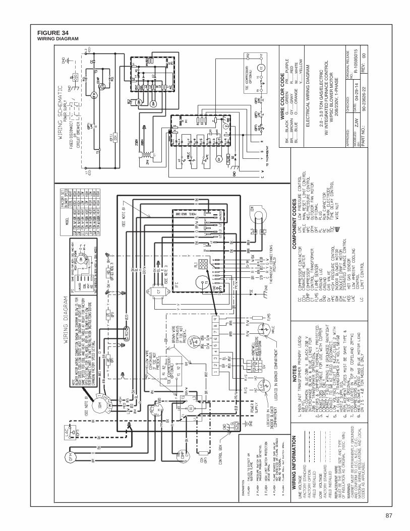
87
FIGURE 34WIRING DIAGRAM
NO
TE
SC
OM
PO
NE
NT
CO
DE
S
WIR
E C
OL
OR
CO
DE
BK
......
BLA
CK
BR
......
BR
OW
NB
L....
...B
LUE
G...
.....G
RE
EN
GY
......
GR
AY
O...
.....O
RA
NG
E
PR
......
PU
RP
LER
......
..RE
DW
......
.WH
ITE
Y....
....Y
ELL
OW
WIR
ING
INFO
RM
AT
ION
WAR
NIN
G-C
ABIN
ET M
UST
BE
PER
MAN
ENTL
Y G
ROU
ND
EDAN
D C
ON
FORM
TO
I.E
.C.,
N.E
.C.,
C.E
.C.,
NAT
ION
AL W
IRIN
G R
EGU
LATI
ON
S, A
ND
LO
CAL
CO
DES
AS
APPL
ICAB
LE.
REP
LAC
EMEN
T W
IRE
-MU
ST B
E TH
E SA
ME
SIZE
AN
D T
YPE
OF
INSU
LATI
ON
AS
OR
IGIN
AL
(105
C.
MIN
.)
-FIE
LD I
NST
ALLE
D-F
ACTO
RY
STAN
DAR
DLO
W
VOLT
AGE
-FIE
LD I
NST
ALLE
D-F
ACTO
RY
OPT
ION
-FAC
TOR
Y ST
AND
ARD
LIN
E VO
LTAG
E
OR
IGIN
AL
RE
LEA
SE
NO
.:
ELE
CTR
ICA
L W
IRIN
G D
IAG
RA
M
MO
DE
LED
BY
:
CH
EC
KE
D:
AP
PR
OV
ED
:
RE
V:
PA
RT
NO
.:
DA
TE:
90-2
3626
-22
00
ZJW
04-2
9-14
R-1
059S
015
2.0
- 3.
0 TO
N G
AS
/ELE
CTR
ICW
/ IN
TEG
RA
TED
FU
RN
AC
E C
ON
TRO
LW
/PS
C B
LOW
ER
MO
TOR
208/
230V
, 1-P
HA
SE
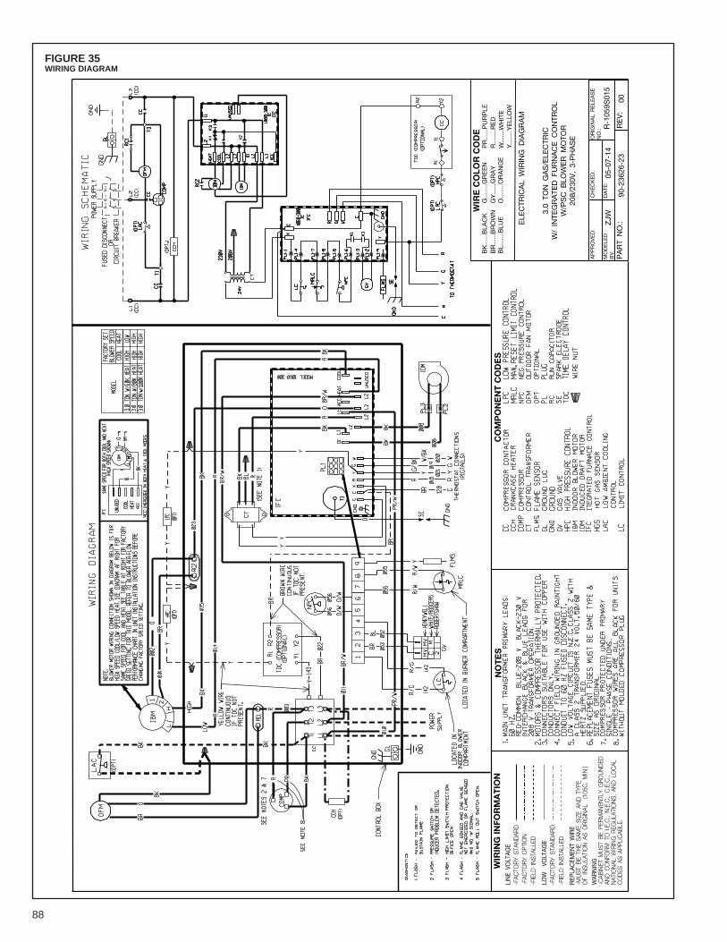
88
FIGURE 35WIRING DIAGRAM
+0
#$
-/
0!
*0
+$
+#
)/0
1$
-
!"#
$%&
'(
'#
%&'
)$
!"
######
!$%
&"
!'
######
!'
()
*!
$####
###!
$+,
-###
#####-
',
,*
-.
######
-'
%.
(###
#####(
'%
*-
,
/'
######
/+
'/
$,'
######
##',
0)
######
#)1
23,
.####
####.
,$$
()
!
2&%
&+,
)&+30
%!
"#
&0+
)%'
*2*
-!"
#$%&
'()*
+,(
)$')
-'.*
#&'&
(/0)
1.2
+&
3'3
#&3
)"2
&42
.*)(
2)%
5'5"
56)&
5'5"
56)"
5'5"
56&
#(%2
&#/
)7%.
%&1
).'1
+/#
(%2
&,6
)#&
3)/
2"
#/"
23
',)#
,)#-
-/%"
#$/'
5!
',/
$%&
,4,*
35)
2',
!*+
,()$
')(8
'),#
*')
,%9'
)#&
3)(
0-'
24)
%&,+
/#(%
2&
)#,)
2.
%1%&
#/))
:;<=
"5)
*%&
5>
!4%'
/3)%
&,(
#//'
3!4
#"(2
.0)
,(#&
3#.
3$(
)55
6($3
%-,
!4%'
/3)%
&,(
#//'
3!4
#"(2
.0)
2-(
%2&
!4#"
(2.
0),(
#&3
#.3
$2*
,56(
$3%-
,
('
2-2*
%$5
',
$,%
7,
*(
#8
,$,
&3'
2&%
$5)
2'2*
-50
2%-
'%
4
4(
0,
$,0
!.
8
&1
,&
",
08
%/
/'
(6
,0
8
',
68
/%
'35
*(
#8
0%
3,8
>;?@
AB@B
?@A5
5555
55;;
CD)
;E?;
F?<G
'?<
;E>7
;<E
A#;5
3(*
5-%
7H,
$,&
3'2&
)H5
2*3,
-'
%3,
05I
+'
*%
&,
5&(
*3'
($
)H/
7&
5!$(
),
'54
(3(
'@;
:H@A
;6=5
A?/
1%
7,

89
FIGURE 36WIRING DIAGRAM
NO
TE
SC
OM
PO
NE
NT
CO
DE
S
WIR
E C
OL
OR
CO
DE
BK......BLA
CK
BR......BROWN
BL.......BLU
E
G........G
REEN
GY......GRAY
O........O
RANGE
PR......PURPLE
R........R
ED
W.......W
HITE
Y........YELL
OW
WIR
ING
INFO
RM
AT
ION
WAR
NING
-CAB
INET
MUST
BE
PERM
ANEN
TLY
GRO
UNDED
AND C
ONFO
RM T
O I.E.C.,
N.E.C.,
C.E.C.,
NAT
IONAL
WIRING R
EGULA
TIONS, A
ND L
OCAL
CODES
AS
APPL
ICAB
LE.
REP
LACEM
ENT
WIRE
-MUST
BE
THE
SAME
SIZE
AND T
YPE
OF
INSU
LATION A
S ORIGINAL
(105
C. MIN.)
-FIELD
INST
ALLE
D-FAC
TORY
STAN
DAR
DLO
W VO
LTAG
E
-FIELD
INST
ALLE
D-FAC
TORY
OPT
ION
-FAC
TORY
STAN
DAR
DLINE
VOLT
AGE
ORIG
INAL
RELE
ASE
NO.:
ELE
CTR
ICAL
WIRING D
IAGRAM
MODELE
DBY:
CHECKED:
APPROVED:
REV:
PART
NO.:
DATE
:
90-236
26-24
00
ZJW
05-07-14
R-105
9S01
5
2.0
- 5.0
TON S
INGLE
STA
GE G
AS/ELE
CTR
ICW/ INTE
GRATE
D F
URNACE C
ONTR
OL
W/ CONSTA
NT
TORQUE B
LOWER M
OTO
R20
8/23
0V, 1-PHASE
Cool
Heat
260
K5
22
80K
53
2.5
60K
52
2.5
80K
53
360
K5
13
80K
52
310
0K5
33.
580
K5
23.
510
0K5
34
80K
52
410
0K5
35
100K
51
Fact
ory
Blow
er S
peed
sCo
nsta
nt T
orqu
e / 1
-Sta
ge C
omp
Cool
ing
(tons
)He
at
Inpu
tSp
eed
Tap

90
FIGURE 37WIRING DIAGRAM
NO
TE
SC
OM
PO
NE
NT
CO
DE
S
WIR
E C
OL
OR
CO
DE
BK......BLA
CK
BR......BROWN
BL.......BLU
E
G........G
REEN
GY......GRAY
O........O
RANGE
PR......PURPLE
R........R
ED
W.......W
HITE
Y........YELL
OW
WIR
ING
INFO
RM
AT
ION
WAR
NING
-CAB
INET
MUST
BE
PERM
ANEN
TLY
GRO
UNDED
AND C
ONFO
RM T
O I.E.C.,
N.E.C.,
C.E.C.,
NAT
IONAL
WIRING R
EGULA
TIONS, A
ND L
OCAL
CODES
AS
APPL
ICAB
LE.
REP
LACEM
ENT
WIRE
-MUST
BE
THE
SAME
SIZE
AND T
YPE
OF
INSU
LATION A
S ORIGINAL
(105
C. MIN.)
-FIELD
INST
ALLE
D-FAC
TORY
STAN
DAR
DLO
W VO
LTAG
E
-FIELD
INST
ALLE
D-FAC
TORY
OPT
ION
-FAC
TORY
STAN
DAR
DLINE
VOLT
AGE
ORIG
INAL
RELE
ASE
NO.:
ELE
CTR
ICAL
WIRING D
IAGRAM
MODELE
DBY:
CHECKED:
APPROVED:
REV:
PART
NO.:
DATE
:
90-236
26-25
00
ZJW
05-07-14
R-105
9S01
5
3.0
- 5.0
TON S
INGLE
STA
GE G
AS/ELE
CTR
ICW/ INTE
GRATE
D F
URNACE C
ONTR
OL
W/ CONSTA
NT
TORQUE B
LOWER M
OTO
R20
8/23
0V, 3-PHASE
Cool
Heat
360
K5
13
80K
52
310
0K5
33.
580
K5
23.
510
0K5
34
80K
52
410
0K5
35
100K
51
Fact
ory
Blow
er S
peed
sCo
nsta
nt T
orqu
e / 1
-Sta
ge C
omp
Cool
ing
(tons
)He
at
Inpu
tSp
eed
Tap

91
FIGURE 38WIRING DIAGRAM
NO
TE
SC
OM
PO
NE
NT
CO
DE
S
WIR
E C
OL
OR
CO
DE
BK......BLA
CK
BR......BROWN
BL.......BLU
E
G........G
REEN
GY......GRAY
O........O
RANGE
PR......PURPLE
R........R
ED
W.......W
HITE
Y........YELL
OW
WIR
ING
INFO
RM
AT
ION
WAR
NING
-CAB
INET
MUST
BE
PERM
ANEN
TLY
GRO
UNDED
AND C
ONFO
RM T
O I.E.C.,
N.E.C.,
C.E.C.,
NAT
IONAL
WIRING R
EGULA
TIONS, A
ND L
OCAL
CODES
AS
APPL
ICAB
LE.
REP
LACEM
ENT
WIRE
-MUST
BE
THE
SAME
SIZE
AND T
YPE
OF
INSU
LATION A
S ORIGINAL
(105
C. MIN.)
-FIELD
INST
ALLE
D-FAC
TORY
STAN
DAR
DLO
W VO
LTAG
E
-FIELD
INST
ALLE
D-FAC
TORY
OPT
ION
-FAC
TORY
STAN
DAR
DLINE
VOLT
AGE
ORIG
INAL
RELE
ASE
NO.:
ELE
CTR
ICAL
WIRING D
IAGRAM
MODELE
DBY:
CHECKED:
APPROVED:
REV:
PART
NO.:
DATE
:
90-236
26-26
00
ZJW
05-07-14
R-106
2S00
1
5.0
TON G
AS/ELE
CTR
ICW/ INTE
GRATE
D F
URNACE C
ONTR
OL
W/ CONSTA
NT
TORQUE B
LOWER M
OTO
RW/ 2-STA
GE C
OMPRESSOR
208/23
0V, 1-PHASE
Cool
Heat
5 (1
st s
tage
)10
0K2
15
(2nd
sta
ge)
100K
51
Cons
tant
Tor
que
/ 2-S
tage
Com
pCo
olin
g (to
ns)
Heat
In
put
Spee
d Ta
p
Fact
ory
Blow
er S
peed
s

92
FIGURE 39WIRING DIAGRAM
NO
TE
SC
OM
PO
NE
NT
CO
DE
S
WIR
E C
OL
OR
CO
DE
BK......BLA
CK
BR......BROWN
BL.......BLU
E
G........G
REEN
GY......GRAY
O........O
RANGE
PR......PURPLE
R........R
ED
W.......W
HITE
Y........YELL
OW
WIR
ING
INFO
RM
AT
ION
WAR
NING
-CAB
INET
MUST
BE
PERM
ANEN
TLY
GRO
UNDED
AND C
ONFO
RM T
O I.E.C.,
N.E.C.,
C.E.C.,
NAT
IONAL
WIRING R
EGULA
TIONS, A
ND L
OCAL
CODES
AS
APPL
ICAB
LE.
REP
LACEM
ENT
WIRE
-MUST
BE
THE
SAME
SIZE
AND T
YPE
OF
INSU
LATION A
S ORIGINAL
(105
C. MIN.)
-FIELD
INST
ALLE
D-FAC
TORY
STAN
DAR
DLO
W VO
LTAG
E
-FIELD
INST
ALLE
D-FAC
TORY
OPT
ION
-FAC
TORY
STAN
DAR
DLINE
VOLT
AGE
ORIG
INAL
RELE
ASE
NO.:
ELE
CTR
ICAL
WIRING D
IAGRAM
MODELE
DBY:
CHECKED:
APPROVED:
REV:
PART
NO.:
DATE
:
90-236
26-27
00
ZJW
05-07-14
R-106
2S00
1
5.0
TON G
AS/ELE
CTR
ICW/ INTE
GRATE
D F
URNACE C
ONTR
OL
W/ CONSTA
NT
TORQUE B
LOWER M
OTO
RW/ 2-STA
GE C
OMPRESSOR
208/23
0V, 3-PHASE
Cool
Heat
5 (1
st s
tage
)10
0K2
15
(2nd
sta
ge)
100K
51
Cons
tant
Tor
que
/ 2-S
tage
Com
pCo
olin
g (to
ns)
Heat
In
put
Spee
d Ta
p
Fact
ory
Blow
er S
peed
s
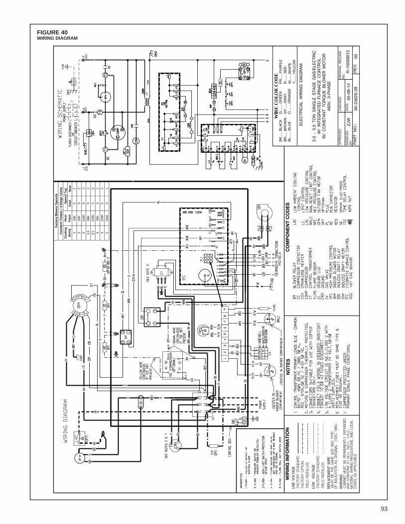
93
FIGURE 40WIRING DIAGRAM
NO
TE
SC
OM
PO
NE
NT
CO
DE
S
WIR
E C
OL
OR
CO
DE
BK......BLA
CK
BR......BROWN
BL.......BLU
E
G........G
REEN
GY......GRAY
O........O
RANGE
PR......PURPLE
R........R
ED
W.......W
HITE
Y........YELL
OW
WIR
ING
INFO
RM
AT
ION
WAR
NING
-CAB
INET
MUST
BE
PERM
ANEN
TLY
GRO
UNDED
AND C
ONFO
RM T
O I.E.C.,
N.E.C.,
C.E.C.,
NAT
IONAL
WIRING R
EGULA
TIONS, A
ND L
OCAL
CODES
AS
APPL
ICAB
LE.
REP
LACEM
ENT
WIRE
-MUST
BE
THE
SAME
SIZE
AND T
YPE
OF
INSU
LATION A
S ORIGINAL
(105
C. MIN.)
-FIELD
INST
ALLE
D-FAC
TORY
STAN
DAR
DLO
W VO
LTAG
E
-FIELD
INST
ALLE
D-FAC
TORY
OPT
ION
-FAC
TORY
STAN
DAR
DLINE
VOLT
AGE
ORIG
INAL
RELE
ASE
NO.:
ELE
CTR
ICAL
WIRING D
IAGRAM
MODELE
DBY:
CHECKED:
APPROVED:
REV:
PART
NO.:
DATE
:
90-236
26-28
00
ZJW
05-08-14
R-105
9S01
5
3.0
- 5.0
TON S
INGLE
STA
GE G
AS/ELE
CTR
ICW/ INTE
GRATE
D F
URNACE C
ONTR
OL
W/ CONSTA
NT
TORQUE B
LOWER M
OTO
R46
0V, 3-PHASE
Cool
Heat
360
K5
13
80K
52
310
0K5
33.
580
K5
23.
510
0K5
34
80K
52
410
0K5
35
100K
51
Fact
ory
Blow
er S
peed
sCo
nsta
nt T
orqu
e / 1
-Sta
ge C
omp
Cool
ing
(tons
)He
at
Inpu
tSp
eed
Tap
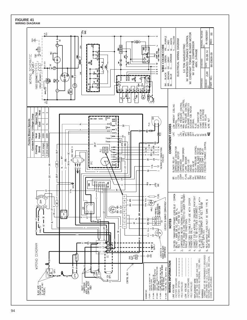
94
FIGURE 41WIRING DIAGRAM
NO
TE
SC
OM
PO
NE
NT
CO
DE
S
WIR
E C
OL
OR
CO
DE
BK......BLA
CK
BR......BROWN
BL.......BLU
E
G........G
REEN
GY......GRAY
O........O
RANGE
PR......PURPLE
R........R
ED
W.......W
HITE
Y........YELL
OW
WIR
ING
INFO
RM
AT
ION
WAR
NING
-CAB
INET
MUST
BE
PERM
ANEN
TLY
GRO
UNDED
AND C
ONFO
RM T
O I.E.C.,
N.E.C.,
C.E.C.,
NAT
IONAL
WIRING R
EGULA
TIONS, A
ND L
OCAL
CODES
AS
APPL
ICAB
LE.
REP
LACEM
ENT
WIRE
-MUST
BE
THE
SAME
SIZE
AND T
YPE
OF
INSU
LATION A
S ORIGINAL
(105
C. MIN.)
-FIELD
INST
ALLE
D-FAC
TORY
STAN
DAR
DLO
W VO
LTAG
E
-FIELD
INST
ALLE
D-FAC
TORY
OPT
ION
-FAC
TORY
STAN
DAR
DLINE
VOLT
AGE
ORIG
INAL
RELE
ASE
NO.:
ELE
CTR
ICAL
WIRING D
IAGRAM
MODELE
DBY:
CHECKED:
APPROVED:
REV:
PART
NO.:
DATE
:
90-236
26-29
00
ZJW
05-08-14
R-106
2S00
1
5.0
TON G
AS/ELE
CTR
ICW/ INTE
GRATE
D F
URNACE C
ONTR
OL
W/ CONSTA
NT
TORQUE B
LOWER M
OTO
RW/ 2-STA
GE C
OMPRESSOR
460V
, 3-PHASE
Cool
Heat
5 (1
st s
tage
)10
0K2
15
(2nd
sta
ge)
100K
51
Cons
tant
Tor
que
/ 2-S
tage
Com
pCo
olin
g (to
ns)
Heat
In
put
Spee
d Ta
p
Fact
ory
Blow
er S
peed
s
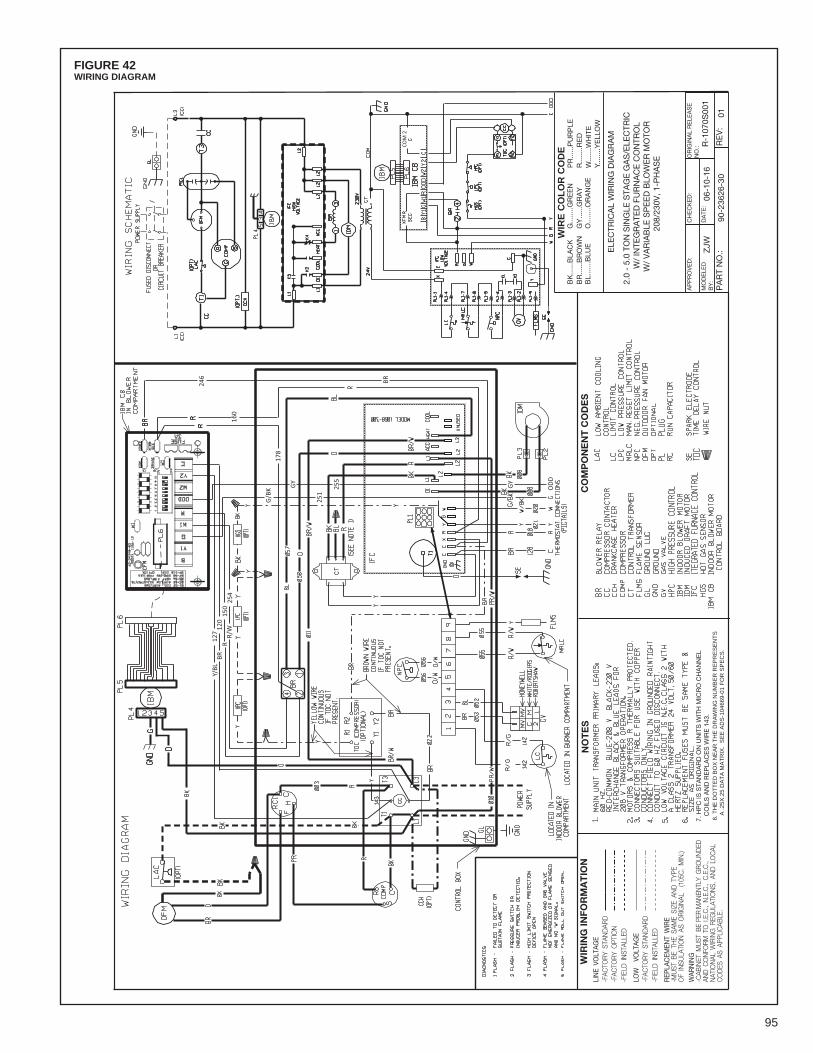
95
FIGURE 42WIRING DIAGRAM
NO
TE
SC
OM
PO
NE
NT
CO
DE
S
WIR
E C
OL
OR
CO
DE
BK
......
BLA
CK
BR
......
BR
OW
NB
L....
...B
LUE
G...
.....G
RE
EN
GY
......
GR
AY
O...
.....O
RA
NG
E
PR
......
PU
RP
LER
......
..RE
DW
......
.WH
ITE
Y....
....Y
ELL
OW
WIR
ING
INFO
RM
AT
ION
WAR
NIN
G-C
ABIN
ET M
UST
BE
PER
MAN
ENTL
Y G
ROU
ND
EDAN
D C
ON
FORM
TO
I.E
.C.,
N.E
.C.,
C.E
.C.,
NAT
ION
AL W
IRIN
G R
EGU
LATI
ON
S, A
ND
LO
CAL
CO
DES
AS
APPL
ICAB
LE.
REP
LAC
EMEN
T W
IRE
-MU
ST B
E TH
E SA
ME
SIZE
AN
D T
YPE
OF
INSU
LATI
ON
AS
OR
IGIN
AL
(105
C.
MIN
.)
-FIE
LD I
NST
ALLE
D-F
ACTO
RY
STAN
DAR
DLO
W
VOLT
AGE
-FIE
LD I
NST
ALLE
D-F
ACTO
RY
OPT
ION
-FAC
TOR
Y ST
AND
ARD
LIN
E VO
LTAG
E
OR
IGIN
AL
RE
LEA
SE
NO
.:
ELE
CTR
ICA
L W
IRIN
G D
IAG
RA
M
MO
DE
LED
BY
:
CH
EC
KE
D:
AP
PR
OV
ED
:
RE
V:
PA
RT
NO
.:
DA
TE:
90-2
3626
-30
01
ZJW
06-1
0-16
R-1
070S
001
2.0
- 5.
0 TO
N S
ING
LE S
TAG
E G
AS
/ELE
CTR
ICW
/ IN
TEG
RA
TED
FU
RN
AC
E C
ON
TRO
LW
/ V
AR
IAB
LE S
PE
ED
BLO
WE
R M
OTO
R20
8/23
0V, 1
-PH
AS
E
7. H
PC
IS S
TAN
DA
RD
ON
UN
ITS
WIT
H M
ICR
O C
HA
NN
EL
C
OIL
S A
ND
RE
PLA
CE
S W
IRE
143
.8.
TH
E D
OT
TE
D B
OX
NE
AR
TH
E D
RA
WIN
G N
UM
BE
R R
EP
RE
SE
NT
S
A .2
5X.2
5 D
AT
A M
AT
RIX
. S
EE
AD
S-1
0466
9-01
FO
R S
PE
CS
.
Y/BL
127
BR12
0R
150
R/W
254
251
G/B
K 255
GY
GY
OD
D
160
BR246
COM
2
178
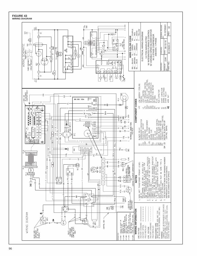
96
FIGURE 43WIRING DIAGRAM
NO
TE
SC
OM
PO
NE
NT
CO
DE
S
WIR
E C
OL
OR
CO
DE
BK
......
BLA
CK
BR
......
BR
OW
NB
L....
...B
LUE
G...
.....G
RE
EN
GY
......
GR
AY
O...
.....O
RA
NG
E
PR
......
PU
RP
LER
......
..RE
DW
......
.WH
ITE
Y....
....Y
ELL
OW
WIR
ING
INFO
RM
AT
ION
WAR
NIN
G-C
ABIN
ET M
UST
BE
PER
MAN
ENTL
Y G
ROU
ND
EDAN
D C
ON
FORM
TO
I.E
.C.,
N.E
.C.,
C.E
.C.,
NAT
ION
AL W
IRIN
G R
EGU
LATI
ON
S, A
ND
LO
CAL
CO
DES
AS
APPL
ICAB
LE.
REP
LAC
EMEN
T W
IRE
-MU
ST B
E TH
E SA
ME
SIZE
AN
D T
YPE
OF
INSU
LATI
ON
AS
OR
IGIN
AL
(105
C.
MIN
.)
-FIE
LD I
NST
ALLE
D-F
ACTO
RY
STAN
DAR
DLO
W
VOLT
AGE
-FIE
LD I
NST
ALLE
D-F
ACTO
RY
OPT
ION
-FAC
TOR
Y ST
AND
ARD
LIN
E VO
LTAG
E
OR
IGIN
AL
RE
LEA
SE
NO
.:
ELE
CTR
ICA
L W
IRIN
G D
IAG
RA
M
MO
DE
LED
BY
:
CH
EC
KE
D:
AP
PR
OV
ED
:
RE
V:
PA
RT
NO
.:
DA
TE:
90-2
3626
-31
02
ZJW
06-1
0-16
R-1
070S
001
5.0
TON
GA
S/E
LEC
TRIC
W/
INTE
GR
ATE
D F
UR
NA
CE
CO
NTR
OL
W/
VA
RIA
BLE
SP
EE
D B
LOW
ER
MO
TOR
W/
2-S
TAG
E C
OM
PR
ES
SO
R20
8/23
0V, 1
-PH
AS
E
7. T
HE
DO
TT
ED
BO
X N
EA
R T
HE
DR
AW
ING
NU
MB
ER
R
EP
RE
SE
NT
S A
.25X
.25
DA
TA
MA
TR
IX.
S
EE
AD
S-1
0466
9-01
FO
R S
PE
CS
.
Y/BL
BR12
0R
155
R/W
254
246
BK
Y13
0
GY
OD
D
160
RR
G/B
KGY 25
1
255
COM
2C
XFM
RSE
CIB
M C
BB
GY1
W1
RO
DD
W2
Y2C
OD
D
Y/BL
178

97
FIGURE 44SYSTEM CHARGE CHARTS
XVI. CHARGE CHARTS
RGEA13/14 – 2 TON COOLINGSYSTEM CHARGE CHART - REFRIGERANT 410A

98
FIGURE 45SYSTEM CHARGE CHARTS
RGEA13/14 – 2.5 TON COOLINGSYSTEM CHARGE CHART - REFRIGERANT 410A
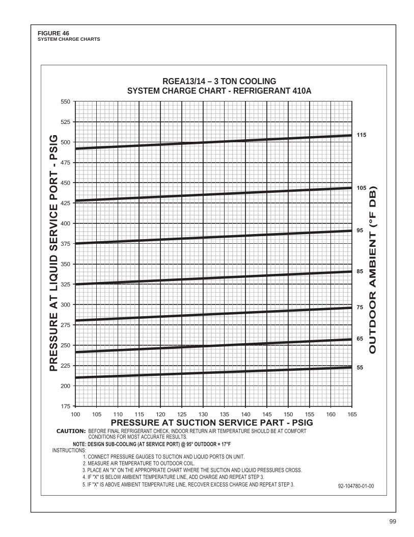
99
FIGURE 46SYSTEM CHARGE CHARTS
RGEA13/14 – 3 TON COOLINGSYSTEM CHARGE CHART - REFRIGERANT 410A

100
FIGURE 47SYSTEM CHARGE CHARTS
RGEA13/14 – 3.5 TON COOLINGSYSTEM CHARGE CHART - REFRIGERANT 410A

101
FIGURE 48SYSTEM CHARGE CHARTS
RGEA13/14 – 4 TON COOLINGSYSTEM CHARGE CHART - REFRIGERANT 410A
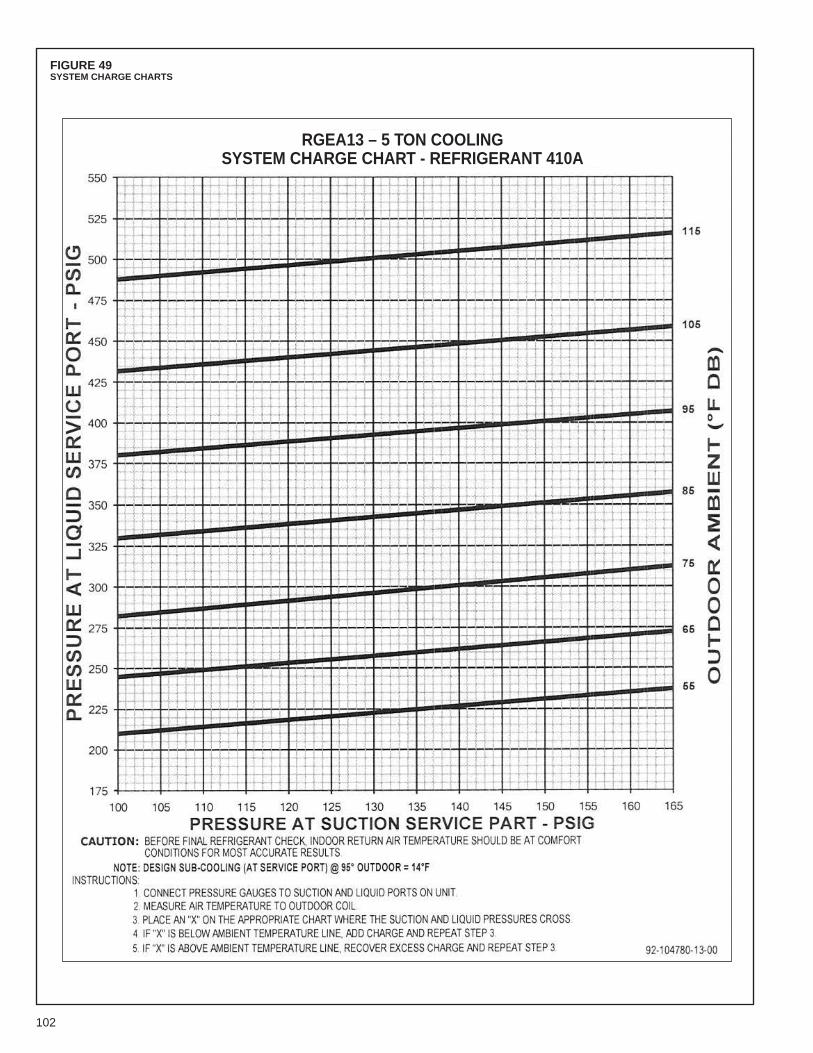
102
FIGURE 49SYSTEM CHARGE CHARTS
RGEA13 – 5 TON COOLINGSYSTEM CHARGE CHART - REFRIGERANT 410A

103
FIGURE 50SYSTEM CHARGE CHARTS
RGEA14 – 5 TON COOLINGSYSTEM CHARGE CHART - REFRIGERANT 410A

104
FIGURE 51SYSTEM CHARGE CHARTS
RGEA15 – 2 TON COOLINGSYSTEM CHARGE CHART - REFRIGERANT 410A

105
RGEA15 – 2.5 TON COOLINGSYSTEM CHARGE CHART - REFRIGERANT 410A
FIGURE 52SYSTEM CHARGE CHARTS

106
RGEA15 – 3 TON COOLINGSYSTEM CHARGE CHART - REFRIGERANT 410A
FIGURE 53SYSTEM CHARGE CHARTS

107
RGEA15 – 3.5 TON COOLINGSYSTEM CHARGE CHART - REFRIGERANT 410A
FIGURE 54SYSTEM CHARGE CHARTS

108
RGEA15 – 4 TON COOLINGSYSTEM CHARGE CHART - REFRIGERANT 410A
FIGURE 55SYSTEM CHARGE CHARTS
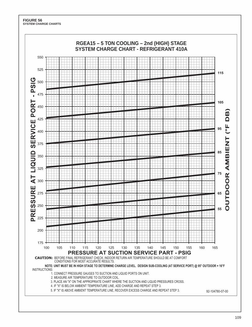
109
RGEA15 – 5 TON COOLING – 2nd (HIGH) STAGESYSTEM CHARGE CHART - REFRIGERANT 410A
FIGURE 56SYSTEM CHARGE CHARTS
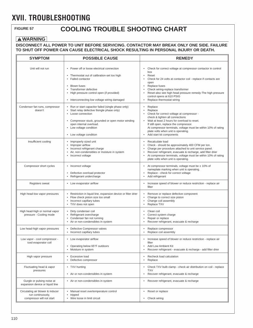
110
WARNING!
DISCONNECT ALL POWER TO UNIT BEFORE SERVICING. CONTACTOR MAY BREAK ONLY ONE SIDE. FAILURETO SHUT OFF POWER CAN CAUSE ELECTRICAL SHOCK RESULTING IN PERSONAL INJURY OR DEATH.
YDEMERESUAC ELBISSOPMOTPMYS
Unit will not run • Power off or loose electrical connection • Check for correct voltage at compressor contactor in controlbox
• Thermostat out of calibration-set too high • Resetera stcatnoc fi ecalper - lioc rotcatnoc ta stlov 42 rof kcehC•rotcatnoc deliaF•
opensesuf ecalpeR•sesuf nwolB•
remrofsnart ecalper-gniriw kcehC•evitcefed remrofsnarT•• High pressure control open (if provided) • Reset-also see high head pressure remedy-The high pressure
control opens at 610 PSIG• Interconnecting low voltage wiring damaged • Replace thermostat wiring
Condenser fan runs, compressor • Run or start capacitor failed (single phase only) • Replacedoesn’t • Start relay defective 9single phase only) • Replace
- rosserpmoc ta egatlov tcerroc rof kcehC•noitcennoc esooL•check & tighten all connections
• Compressor stuck, grounded or open motor winding • Wait at least 2 hours for overload to reset..rosserpmoc eht ecalper ,nepo llits fI.daolrevo lanretni nepo
gnitar fo %01 nihtiw eb tsum egatlov ,slanimret rosserpmoc tAnoitidnoc egatlov woL•plate volts when unit is operating.
stnenopmoc tik trats ddA•noitidnoc egatlov woL•
daol etaluclaceR•tinu dezis ylreporpmI•gnilooc tneiciffusnI.not rep MFC 004 yletamixorppa eb dluohs - kcehC•wolfria reporpmI•
.lenap ecivres tinu ot dehcatta erudecorp rep egrahC•egrahc tnaregirfer tcerrocnI•• Air, non-condensibles or moisture in system • Recover refrigerant, evacuate & recharge, add filter drier
gnitar fo %01 nihtiw eb tsum egatlov ,slanimret rosserpmoc tA•egatlov tcerrocnI•plate volts when unit is operating.
fo %01 ± eb tsum egatlov ,slanimret rosserpmoc tA•egatlov tcerrocnI•selcyc trohs rosserpmoCnameplate marking when unit is operating.
egatlov tcerroc rof kcehc - ecalpeR•rotcetorp daolrevo evitcefeD•tnaregirfer ddA•egrahcrednu tnaregirfeR•
ria ecalper - noitcirtser ecuder ro rewolb fo deeps esaercnI•wolfria rotaropave woL•taews sretsigeRfilter
High head-low vapor pressures • Restriction in liquid line, expansion device or filter drier • Remove or replace defective componentnotsip ezis tcerroc ot egnahC•llams oot ezis notsip kcehc wolF•
ylbmessa lioc egnahC•sebut yrallipac tcerrocnI•VXT ecalpeR•nepo ton seod VXT•
lioc naelC•lioc resnednoc ytriD•ropav lamron ro hgih-daeh hgiHegrahc metsys tcerroC•egrahcrevo tnaregirfeR•edom gnilooC - erusserp
ecalper ro riapeR•gninnur ton naf resnednoC•egrahcer & etaucave ,tnaregirfer revoceR•metsys ni selbisnednoc-non ro riA•
rosserpmoc ecalpeR•sevlav rosserpmoC evitcefeD•serusserp ropav hgih-daeh woLylbmessa lioc ecalpeR•sebut yrallipac tcerrocnI•
ria ecalper - noitcirtser ecuder ro rewolb fo deeps esaercnI•wolfria rotaropave woL•- rosserpmoc looc - ropav woLiced evaporator coil filter
tiK tneibmA woL ddA•sroodtuo F°56 woleb gnitarepO•reird retlif dda - egrahcer & etaucave - tnaregirfer revoceR•metsys ni erutsioM•
noitaluclac daol kcehceR•daol evissecxE•erusserp ropav hgiHecalpeR•rosserpmoc evitcefeD•
ecalper - lioc no noitubirtsid ria kcehc - pmalc blub VXT kcehC•gnitnuh VXT•ropav & daeh gnitautculFpressures TXV
egrahcer & etaucave ,tnaregirfer revoceR•metsys ni selbisnednoc-non ro riA•
egrahcer & etaucave ,tnaregirfer revoceR•metsys ni selbisnednoc-non ro riA•ta esion gnislup ro elgruGexpansion device or liquid line
Circulating air blower & inducer • Manual reset overtemperature control • Reset or replacerun continuously, • tripped
gniriw kcehC•tiucric timil ni esool eriW•trats ton lliw rosserpmoc
COOLING TROUBLE SHOOTING CHART
XVII. TROUBLESHOOTINGFIGURE 57
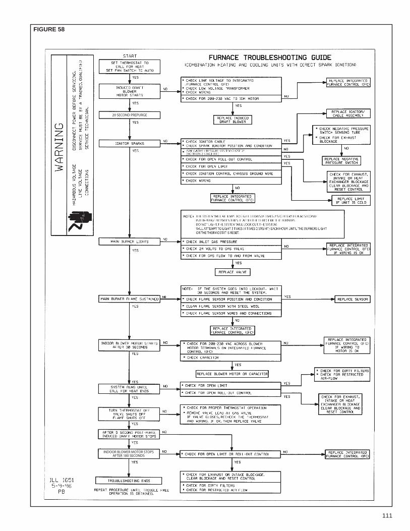
111
FIGURE 58
20 SECOND PREPURGE
INDOOR BLOWER MOTOR STOPSAFTER 180 SECONDS
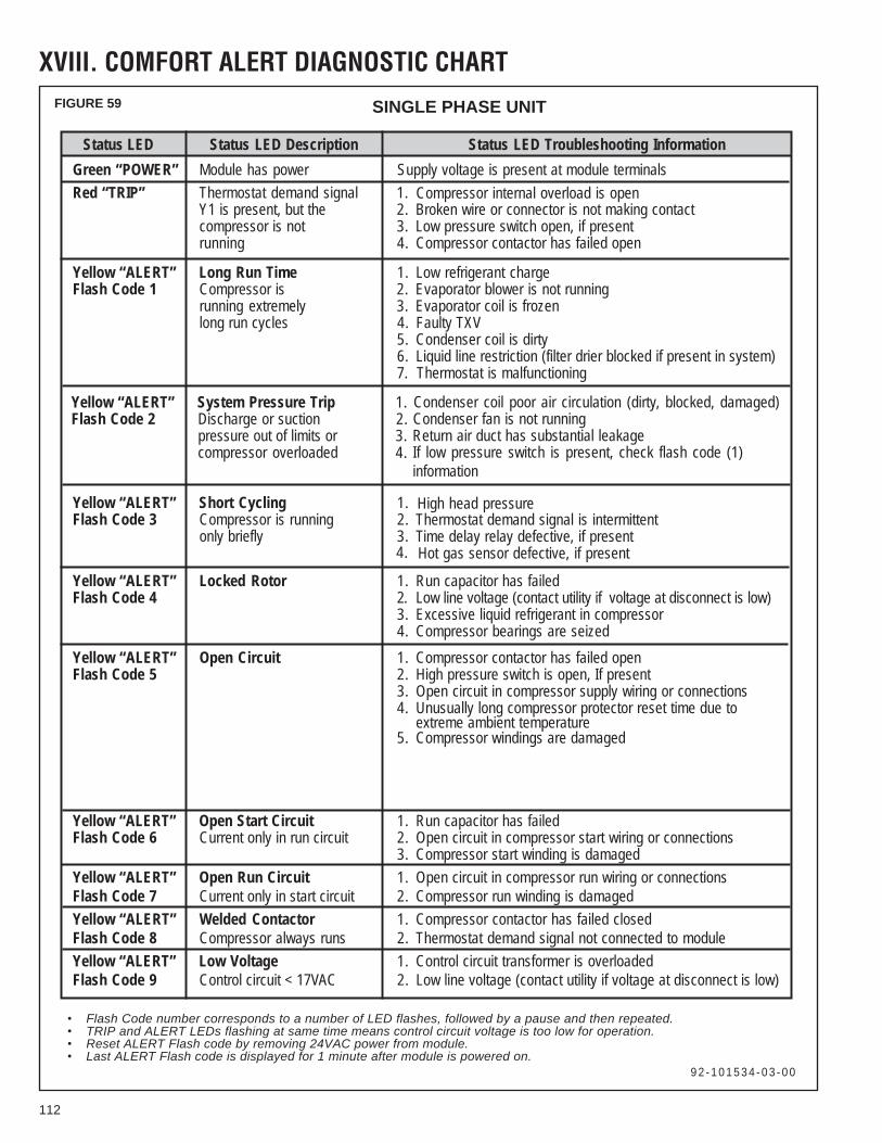
112
FIGURE 59
Status LED Status LED Description Status LED Troubleshooting InformationGreen “POWER” Module has power Supply voltage is present at module terminalsRed “TRIP” Thermostat demand signal 1. Compressor internal overload is open
Y1 is present, but the 2. Broken wire or connector is not making contactcompressor is not 3. Low pressure switch open, if presentrunning 4.
4.
4.
Compressor contactor has failed open
Yellow “ALERT” Long Run Time 1. Low refrigerant chargeFlash Code 1 Compressor is 2. Evaporator blower is not running
running extremely 3. Evaporator coil is frozenlong run cycles 4. Faulty TXV
5. Condenser coil is dirty6. Liquid line restriction (filter drier blocked if present in system)7. Thermostat is malfunctioning
Yellow “ALERT” System Pressure Trip 1. Flash Code 2 Discharge or suction 2.
Condenser coil poor air circulation (dirty, blocked, damaged)
pressure out of limits or 3.Condenser fan is not running
compressor overloadedReturn If low pressure switch is present, check flash code (1)information
air duct has substantial leakage
Yellow “ALERT” Short Cycling 1.Thermostat demand signal is intermittent
Hot gas sensor defective, if present
Flash Code 3 Compressor is running 2.Time delay relay defective, if presentonly briefly 3.
Yellow “ALERT” Locked Rotor 1. Run capacitor has failedFlash Code 4 2. Low line voltage (contact utility if voltage at disconnect is low)
3. Excessive liquid refrigerant in compressor4. Compressor bearings are seized
Yellow “ALERT” Open Circuit 1. Compressor contactor has failed openFlash Code 5 2. High pressure switch is open, If present
3. Open circuit in compressor supply wiring or connections4. Unusually long compressor protector reset time due to
extreme ambient temperature5. Compressor windings are damaged
Yellow “ALERT” Open Start Circuit 1. Run capacitor has failedFlash Code 6 Current only in run circuit 2. Open circuit in compressor start wiring or connections
3. Compressor start winding is damagedYellow “ALERT” Open Run Circuit 1. Open circuit in compressor run wiring or connectionsFlash Code 7 Current only in start circuit 2. Compressor run winding is damagedYellow “ALERT” Welded Contactor 1. Compressor contactor has failed closedFlash Code 8 Compressor always runs 2. Thermostat demand signal not connected to moduleYellow “ALERT” Low Voltage 1. Control circuit transformer is overloadedFlash Code 9 Control circuit < 17VAC 2. Low line voltage (contact utility if voltage at disconnect is low)
Flash Code number corresponds to a number of LED flashes, followed by a pause and then repeated.TRIP and ALERT LEDs flashing at same time means control circuit voltage is too low for operation.Reset ALERT Flash code by removing 24VAC power from module.Last ALERT Flash code is displayed for 1 minute after module is powered on.
9 2 - 1 0 1 5 3 4 - 0 3 - 0 0
High head pressure
XVIII. COMFORT ALERT DIAGNOSTIC CHART
SINGLE PHASE UNIT

113
FIGURE 60
Status LED Status LED Description Status LED Troubleshooting InformationGreen “POWER” Module has power Supply voltage is present at module terminalsRed “TRIP” Thermostat demand signal 1. Compressor internal overload is open
Y1 is present, but the 2. Broken wire or connector is not making contactcompressor is not 3. Low pressure switch open, if presentrunning 4. Compressor contactor has failed
Yellow “ALERT” A. Low refrigerant chargeB. Evaportaor blower is not runningC. Evaporator coil is frozenD. Faulty TXVE. Condenser coil is dirtyF. Liquid line restriction (filter drier blocked, if present in system)G. Thermostat is malfunctioning
A. Low refrigerant chargeB. Evaportaor blower is not runningC. Evaporator coil is frozenD. Faulty TXVE. Condenser coil is dirtyF. Liquid line restriction (filter drier blocked, if present in system)G. Thermostat is malfunctioning
LED on SolidA short circuit orover-current condition existson "P" terminal
Yellow “ALERT” System Pressure Trip 1. Flash Code 2 Discharge or suction 2.
Condenser coil poor air circulation (dirty, blocked, damaged)
pressure out of limits or 3.Condenser fan is not running
compressor overloadedReturn
4. If low pressure switch is present: air duct has substantial leakage
Yellow “ALERT” Short Cycling 1.Thermostat demand signal is intermittentFlash Code 3 Compressor is running 2.T ime delay relay defective, if presentonly briefly 3.
4.
Yellow “ALERT” Locked Rotor 1.Flash Code 4 2.
Low line voltage (contact utility if voltage at disconnect is low)
3.Excessive liquid refrigerant in compressorCompressor bearings are seized
Hot gas sensor defective, if present
Yellow “ALERT” Open Circuit 1.Flash Code 5 2.
3.
Compressor contactor has failed open
4.
High pressure switch is open, if present
5.
Open circuit in compressor supply wiring or connectionsUnusually long compressor protector reset time due toextreme ambient temperatureCompressor windings are damaged
Yellow “ALERT” Missing Phase 1. Broken wire or connector on one phaseFlash Code 6
"Lockout"
"Lockout"
"Lockout"
2. Compressor motor winding is damaged3. Utility supply has dropped one phase
Yellow “ALERT” Reverse Phase 1. Compressor running backwards due to supply phase reversalFlash Code 7 "Lockout"
"Lockout"
Yellow “ALERT” Welded Contactor 1. Compressor contactor has failed closedFlash Code 8 Compressor always runs 2. Thermostat demand signal not connected to moduleYellow “ALERT” Low Voltage 1. Control circuit transformer is overloadedFlash Code 9 Control circuit < 18VAC 2. Low line voltage (contact utility if voltage at disconnect is low)
• Flash Code number corresponds to a number of LED flashes, followed by a pause and then repeated.• TRIP and ALERT LEDs flashing at same time means control circuit voltage is too low for operation.• Reset ALERT Flash code by removing 24VAC power from module.• Last ALERT Flash code is displayed for 1 minute after module is powered on.
9 2 - 1 0 1 5 3 4 - 0 4 - 0 0
High head pressure
3 PHASE UNIT

114

115

CM 0816116


![Rheem Classic Series Package Gas Electric Unit...FORM NO. R11-870 REV. 5 Air Package Gas Electric RGEA14/15 Series RGEA14- 1 4 SEER Series Nominal Sizes 2-5 Tons [7.0-17.6 kW] RGEA15-](https://img.dokumen.tips/doc/110x75/5ea104be509f502dfa075f3e/rheem-classic-series-package-gas-electric-unit-form-no-r11-870-rev-5-air-package.jpg)


