Embed Size (px)
Citation preview

Operation Manual
914
● Please read and observe the informationgiven in this Operation Manual. This willenable you to avoid accidents, preserve themanufacturer’s warranty and maintain theengine in peak operating condition.
● This engine has been built exclusively forthe application specified in the scope ofsupply, as described by the equipment manu-facturer and is to be used only for theintended purpose. Any use exceeding thatscope is considered to be contrary to theintended purpose. The manufacturer willnot assume responsibility for any damageresulting therefrom. The risks involved areto be borne solely by the user.
● Use in accordance with the intended pur-pose also implies compliance with the con-ditions laid down by the manufacturer foroperation, maintenance and servicing. Theengine should only be operated by person-nel trained in its use and the hazards in-volved.
● The relevant accident prevention guidelinesand other generally accepted safety andindustrial hygiene regulations must be ob-served.
● When the engine is running, there is a risk ofinjury through:- turning/hot components- engines with positive ignition- ignition systems (high electrical voltage) You must avoid contact at all times!
● Unauthorized engine modifications will in-validate any liability claims against the manu-facturer for resultant damage.Manipulations of the injection and regulatingsystem may also influence the performanceof the engine, and its emissions. Adherenceto legislation on pollution cannot be guaran-teed under such conditions.
● Do not change, convert or adjust the coolingair intake area to the blower.The manufacturer shall not be held respon-sible for any damage which results fromsuch work.
● When carrying out maintenance/repair op-erations on the engine, the use of DEUTZoriginal parts is prescribed. These are spe-cially designed for your engine and guaran-tee perfect operation.Non-compliance results in the expiry of thewarranty!
● Maintenance and cleaning of the engineshould only be carried out when the engineis switched off and has cooled down.You must ensure that the electrical systemshave been switched off and the ignition keyhas been removed.Accident prevention guidelines concerningelectrical systems (e.g. VDE-0100/-0101/-0104/-0105 Electrical protective measuresagainst dangerous touch voltage) are to beobserved.When cleaning with fluids, all electrical com-ponents are to be covered impermeably.
Safety guidelines / Accident prevention

Operation Manual
914
0312 0382 en
Engine Serial Number
Technical modifications required to improveour engines are reserved with regard to speci-fication data and other technical informationcontained in this Operation Manual. No parts ofthis Manual may be reproduced in any form orby any means without our written approval.
Please enter the engine serial number here.This number should be quoted when inquiringabout Customer Service, Repairs or SpareParts (see Section 2.1).

Foreword
Dear Customer,
Air / liquid-cooled Deutz engines are designedfor a large number of applications. Conse-quently, a wide range of variants is offered tomeet the requirements of specific cases.
Your engine is appropriately equipped for theinstallation concerned, which means that notall of the components described in this Opera-tion Manual are necessarily mounted to yourengine.
We have endeavoured to highlight any differ-ences so that you will be able to locate thesesdifferences relevant to your engine.
Please read this Manual before starting yourengine, and always observe the operating andmaintenance instructions.
We are available to help with any additionalinquiries
Sincerely,DEUTZ AG

Index
1 General2 Engine Description2.1 Model2.1.1 Rating Plate2.1.2 Position of the Rating Plate2.1.3 Engine Serial Number2.1.4 Cylinder numbering2.1.5 Direct injection2.2 Engine Illustrations2.2.1 Operation side BF3L 9142.2.2 Air outlet side BF3L 9142.2.3 Operation side F4L 9142.2.4 Air outlet side F4L 9142.2.5 Operation side BF6L 914
Intercooler over air-intake line2.2.6 Air outlet side BF6L 914 C
Intercooler over air-intake line2.2.7 Operation side BF6L 914 C
Intercooler over flywheel2.2.8 Air outlet side BF6L 914
Intercooler over flywheel2.3 Lube Oil Circuit Schematic2.3.1 Lube Oil Circuit Schematic2.4 Fuel System Plan2.4.1 Fuel System2.5 Engine cooling2.5.1 Amount of cool air regulated by
exhaust thermostat2.5.2 Amount of cool air regulated by
exhaust thermostat and solenoid valve3 Engine Operation3.1 Commissioning3.1.1 Pour in Engine Oil3.1.2 Filling Oil Bath Air Filter with Engine Oil3.1.3 Pour in Fuel3.1.4 Bleed3.1.5 Other Preparations3.1.6 Additional maintenance work3.1.7 Change-over switch for oil heater
3.2 Starting3.2.1 Starting3.3 Monitoring Operation3.3.1 Engine Oil Pressure3.3.2 Engine temperature3.3.3 Cooling fan drive3.4 Shutting off3.4.1 Mechanical shut-off3.4.2 Electrical shut-off3.5 Operating Conditions3.5.1 Winter Operation3.5.2 High Ambient Temperature, High
Altitude4 Operating Media4.1 Lube Oil4.1.1 Quality4.1.2 Viscosity4.2 Fuel4.2.1 Quality4.2.2 Winter Fuel5 Routine Maintenance5.1 Maintenance Plan5.2 Maintenance Diagram5.3 Maintenance Work Completed6 Service and Maintenance6.1 Lube oil system6.1.1 Oil change intervals6.1.2 Check Oil Level / Change Engine Oil6.1.3 Replace Oil Filter6.1.4 Change bypass-oil filter use6.2 Fuel System6.2.1 Replace fuel filter6.2.2 Precleaning fuel/clean fuel filter6.3 Cooling system6.3.1 Cleaning Intervals6.4 Combustion Air Filter6.4.1 Cleaning Intervals6.4.2 Emptying Cyclone Type Precleaner
6.4.3 Clean Oil Bath Air Filter6.4.4 Dry Type Air Cleaner6.5 Belt Drives6.5.1 Check V-belts6.5.2 Change fan belt6.5.3 Tension alternator belts6.5.4 Change alternator belts6.5.5 Check warning system6.5.6 Tension/change air compressor
belts6.5.7 Air compressor model with dual belts6.6 Adjustments6.6.1 Check valve clearance
(adjust if necessary)6.7 Accessories6.7.1 Battery6.7.2 Rotary Current Alternator6.7.3 Transportation Shackles6.8 Engine cleaning6.8.1 Engine cleaning6.9 Additional Maintenance Work6.9.1 Check fastenings6.9.2 Check functioning of glow plugs7 Faults, Causes and Remedies7.1 Fault Table8 Engine Preservation8.1 Preservation8.1.1 Preserve engine8.1.2 Remove engine preservation9 Technical Specification9.1 Engine Specifications and
Settings9.2 Screw Tightening Torques9.3 Tools
10 Service

1DEUTZ Diesel Engines
are the product of many years of research anddevelopment. The resulting know-how, coupledwith stringent quality standards, guarantee theirlong service life, high reliability and low fuelconsumption.It goes without saying that DEUTZ Diesel Enginesmeet the highest standards for environmentalprotection.
Service
Please contact one of our authorized servicerepresentatives in the event of breakdowns or forspare parts inquiries. Our trained specialists willcarry out repairs quickly and professionally, usingonly genuine spare parts.Original parts from DEUTZ AG are always producedin accordance with state-of-the-art technology.Please turn to the end of this manual for furtherservice information.
General
!
Care and Maintenance
Sound care and maintenance practices will ensurethat the engine continues to meet the requirementsplaced on it. Recommended service intervals mustbe observed and service and maintenance workcarried out conscientiously.Special care should be taken under abnormallydemanding operating conditions.
Asbestos
DEUTZ original parts are asbestos-free.
Safety
This symbol is used for all safetywarnings. Please follow themcarefully. The attention of operatingpersonnel should be drawn to thesesafety instructions. General safety
and accident prevention regulations laid down bylaw must also be observed.
Beware of Running Engine
Shut the engine down before carrying out mainte-nance or repair work. Ensure that the engine cannotbe accidentally started. Risk of accidents.When the work is complete, be sure to refit anypanels and guards that may have been removed.Never fill the fuel tank while the engine is running.Observe industrial safety regulations when runningthe engine in an enclosed space or underground.
CaliforniaProposition 65 Warning
Diesel engine exhaust and some of its consti-tuents are known to the State of California tocause cancer, birth defects, and other repro-ductive harm.

1

2
© 2
001
Engine Description
2.1 Model2.2 Engine Illustrations2.3 Lube Oil Circuit Schematic2.4 Fuel System Plan2.5 Engine cooling

2
© 2
001
The engine serial number is stamped on thecrankcase (arrow) as well as the ratingplate.
2.1.2 Position of the RatingPlate
2.1.3 Engine Serial Number
Engine Description 2.1 Model
2.1.1 Rating Plate
The model A, the engine serial number B andthe performance data are stamped on therating plate.The model and engine serial number must begiven when ordering parts.
The rating plate C is attached to the crankcase.Depending on the model, a second ratingplate may be affixed to the air duct hood.
© 34 570 0 © 34 571 0 © 34 572 0
2
© 2
001
© 35 215 0
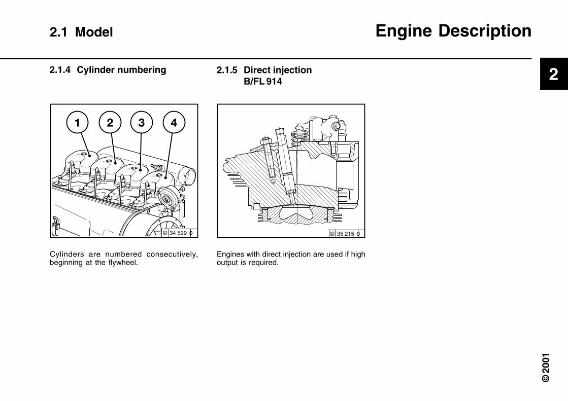
Cylinders are numbered consecutively,beginning at the flywheel.
2.1 Model Engine Description
2.1.4 Cylinder numbering 2.1.5 Direct injectionB/FL 914
Engines with direct injection are used if highoutput is required.
© 34 599 0

2
© 2
001
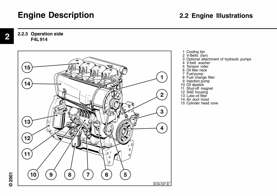
1 Cooling fan2 V-Belts (fan)3 Optional attachment of hydraulic pumps4 V-belt washer5 Tension roller6 Oil pan7 Oil drain screw8 Oil filler neck9 Oil dipstick
10 Fuel change filter11 Solenoid (shut-off magnet)12 Lube oil filter13 Full-stop depending on charge air pressure14 Air duct hood15 Cylinder head cover
Engine Description 2.2 Engine Illustrations
2.2.1 Operation sideBF3L 914
© 34 575 0
2
© 2
001
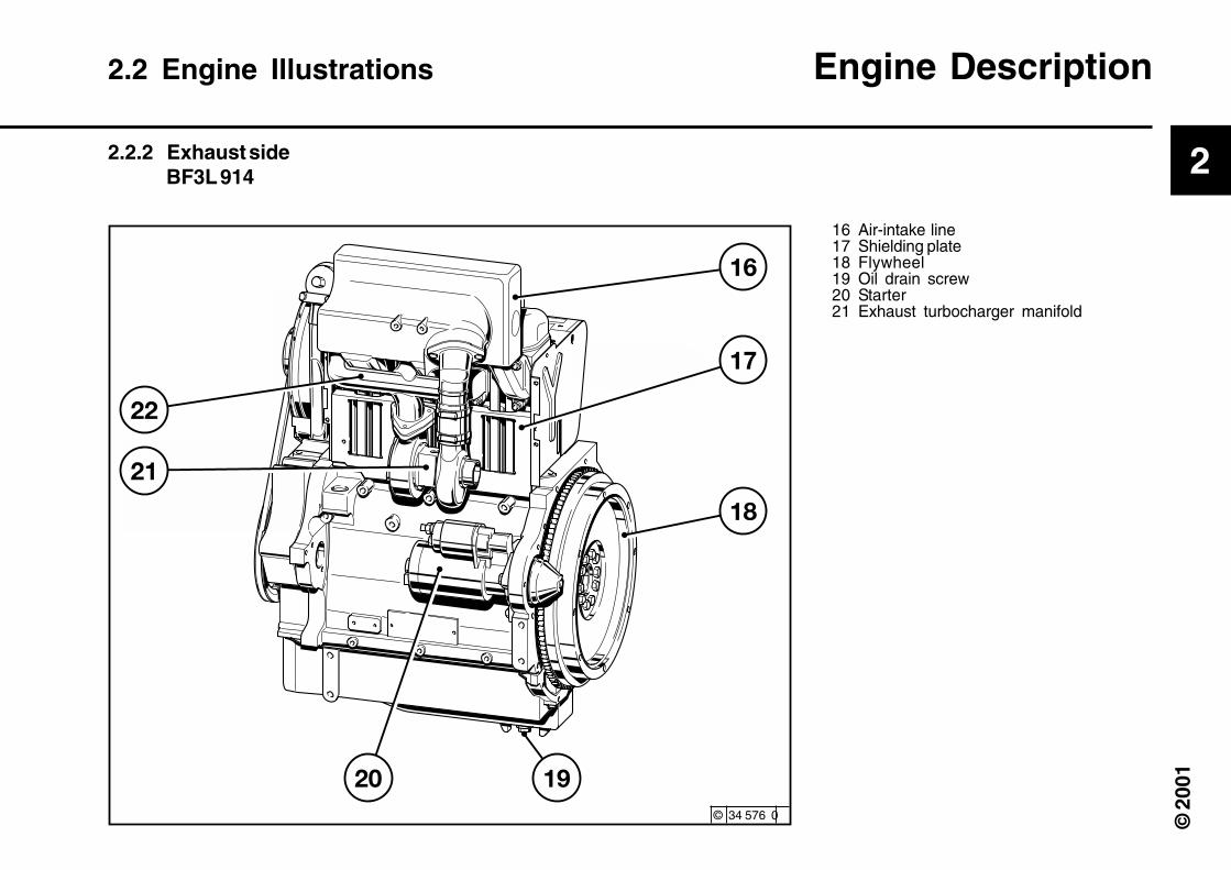
16 Air-intake line17 Shielding plate18 Flywheel19 Oil drain screw20 Starter21 Exhaust turbocharger manifold
2.2 Engine Illustrations Engine Description
2.2.2 Exhaust sideBF3L 914
© 34 576 0
2
© 2
001
1 Cooling fan2 V-Belts (fan)3 Optional attachment of hydraulic pumps4 V-belt washer5 Tension roller6 Oil filler neck7 Fuel pump8 Fuel change filter9 Injection pump
10 Oil dipstick11 Shut-off magnet12 SAE housing13 Lube oil filter14 Air duct hood15 Cylinder head cove
Engine Description 2.2 Engine Illustrations
2.2.3 Operation sideF4L 914
© 34 597 0
2
© 2
001
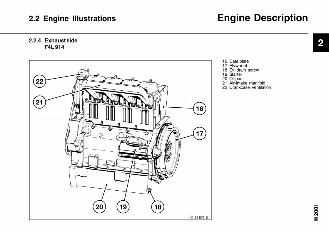
16 Date plate17 Flywheel18 Oil drain screw19 Starter20 Oil pan21 Air-intake manifold22 Crankcase ventilation
2.2 Engine Illustrations Engine Description
2.2.4 Exhaust sideF4L 914
© 34 576 0

2
© 2
001
1 Cooling fan2 V-Belts (fan)3 V-belt pulley on crankshaft4 Tension roller5 Oil filler neck6 Oil drain screw7 Fuel pump with fuel precleaning8 Fuel filter cartridge9 Injection pump
10 Shut-off lifting magnet11 Oil dipstick12 LDA13 Lube oil filter cartridge14 Engine oil cooler15 Air duct hood16 Cylinder head cover
2.2 Engine Illustrations Engine Description
2.2.5 Operation sideBF6L 914 C- intercooler over air-intake line
© 34 577 0

2
© 2
001
17 Intercooler18 Air-intake line19 Exhaust manifold line20 Date plate21 Flywheel22 Starter23 Oil drain screw24 Turbocharger25 Air-intake manifold to exhaust turbocharger26 Alternator
2.2 Engine Illustrations Engine Description
2.2.6 Exhaust sideBF6L 914 C- intercooler over air-intake line
© 34 578 0

2
© 2
001
1 Cooling fan2 V-Belts (fan)3 V-belt pulley on crankshaft4 Tension roller5 Oil filler neck6 Oil drain screw7 Fuel pump with fuel precleaning8 Fuel filter cartridge9 Injection pump
10 Shut-off lifting magnet11 Oil dipstick12 LDA13 Lube oil filter cartridge14 Engine oil cooler15 Air duct hood16 Cylinder head cover
Engine Description 2.2 Engine Illustrations
2.2.7 Operation sideBF6L 914 C- intercooler over flywheel
© 35 579 0

2
© 2
001
17 Intercooler18 Flywheel19 Starter20 Oil drain screw21 Alternator22 Exhaust connection supports23 Exhaust manifold line24 Air-intake manifold to exhaust turbocharger
2.2 Engine Illustrations Engine Description
2.2.8 Exhaust sideBF6L 914 - intercooler over flywheel
© 34 580 0

2
© 2
001
1 Oil pan2 Intake manifold3 Oil pump4 Oil pressure regulating valve5 Pressure oil line6 Short-circuit line or alternative7 Ribbed tube coil or alternative8 Block oil cooler9 Lube oil filter
10 Safety valve11 Main oil channel12 Crankshaft bearing13 Con-rod bearing14 Camshaft bearing15 Tappet16 Pushrod (hollow, for oil intake to lubricate
rocker arm)17 Rocker arm bearings18 Rocker arm lubrication19 Pushrod protective tube20 Throttle bore (to lubricate cogwheels)21 Spray nozzle for piston cooling22 Connection for oil pressure gauge23 Oil pressure gauge24 Injection pump connected to lube oil circuit
schematic25 Connection option for oil heater **
** here the filter carrier must be exchanged.Please contact DEUTZ Service whenchanging-over.
Engine Description 2.3 Lube Oil Circuit Schematic
2.3.1 Lube Oil Circuit SchematicFL 914
© 34 581 0
24
2
© 2
001
© 35 583 0
2.3 Lube Oil Circuit Schematic Engine Description
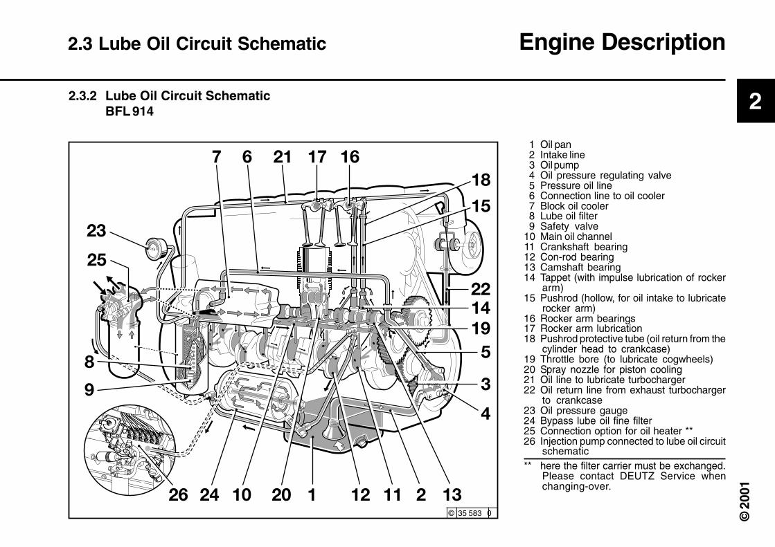
1 Oil pan2 Intake line3 Oil pump4 Oil pressure regulating valve5 Pressure oil line6 Connection line to oil cooler7 Block oil cooler8 Lube oil filter9 Safety valve
10 Main oil channel11 Crankshaft bearing12 Con-rod bearing13 Camshaft bearing14 Tappet (with impulse lubrication of rocker
arm)15 Pushrod (hollow, for oil intake to lubricate
rocker arm)16 Rocker arm bearings17 Rocker arm lubrication18 Pushrod protective tube (oil return from the
cylinder head to crankcase)19 Throttle bore (to lubricate cogwheels)20 Spray nozzle for piston cooling21 Oil line to lubricate turbocharger22 Oil return line from exhaust turbocharger
to crankcase23 Oil pressure gauge24 Bypass lube oil fine filter25 Connection option for oil heater **26 Injection pump connected to lube oil circuit
schematic** here the filter carrier must be exchanged.
Please contact DEUTZ Service whenchanging-over.
2.3.2 Lube Oil Circuit SchematicBFL 914

2
© 2
001
1 Fuel tank2 Fuel line from tank to fuel pump3 Fuel pump4 Fuel change filter5 Injection pump6 Injection line7 Injection valve8 Fuel overflow pipe
A Distance: must be routed as far away fromeach other as possible
Engine Description 2.4 Fuel System Schematic
2.4.1 Fuel System
© 35 582 0
2
© 2
001
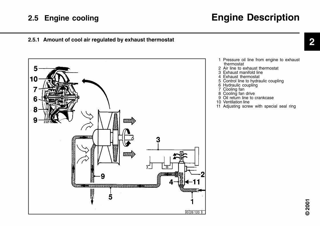
1 Pressure oil line from engine to exhaustthermostat
2 Air line to exhaust thermostat3 Exhaust manifold line4 Exhaust thermostat5 Control line to hydraulic coupling6 Hydraulic coupling7 Cooling fan8 Cooling fan drive9 Oil return line to crankcase
10 Ventilation line11 Adjusting screw with special seal ring
2.5.1 Amount of cool air regulated by exhaust thermostat
2.5 Engine cooling Engine Description
© 26 120 1

2
© 2
001
1 Pressure oil line from engine to exhaustthermostat
2 Air line to exhaust thermostat3 Exhaust manifold line4 Exhaust thermostat5 Control line to hydraulic coupling6 Hydraulic coupling7 Cooling fan8 Cooling fan drive9 Oil return line to crankcase
10 Ventilation line11 Adjusting screw with special seal ring12 Solenoid valve
2.5.2 Amount of cool air regulated by exhaust thermostat and soleno-id valve
Engine Description 2.5 Engine cooling
© 26 121 2

3
© 2
001
Engine Operation
3.1 Commissioning3.2 Starting3.3 Monitoring Operation3.4 Shutting off3.5 Operating Conditions
3
© 2
001
© 35 201 0
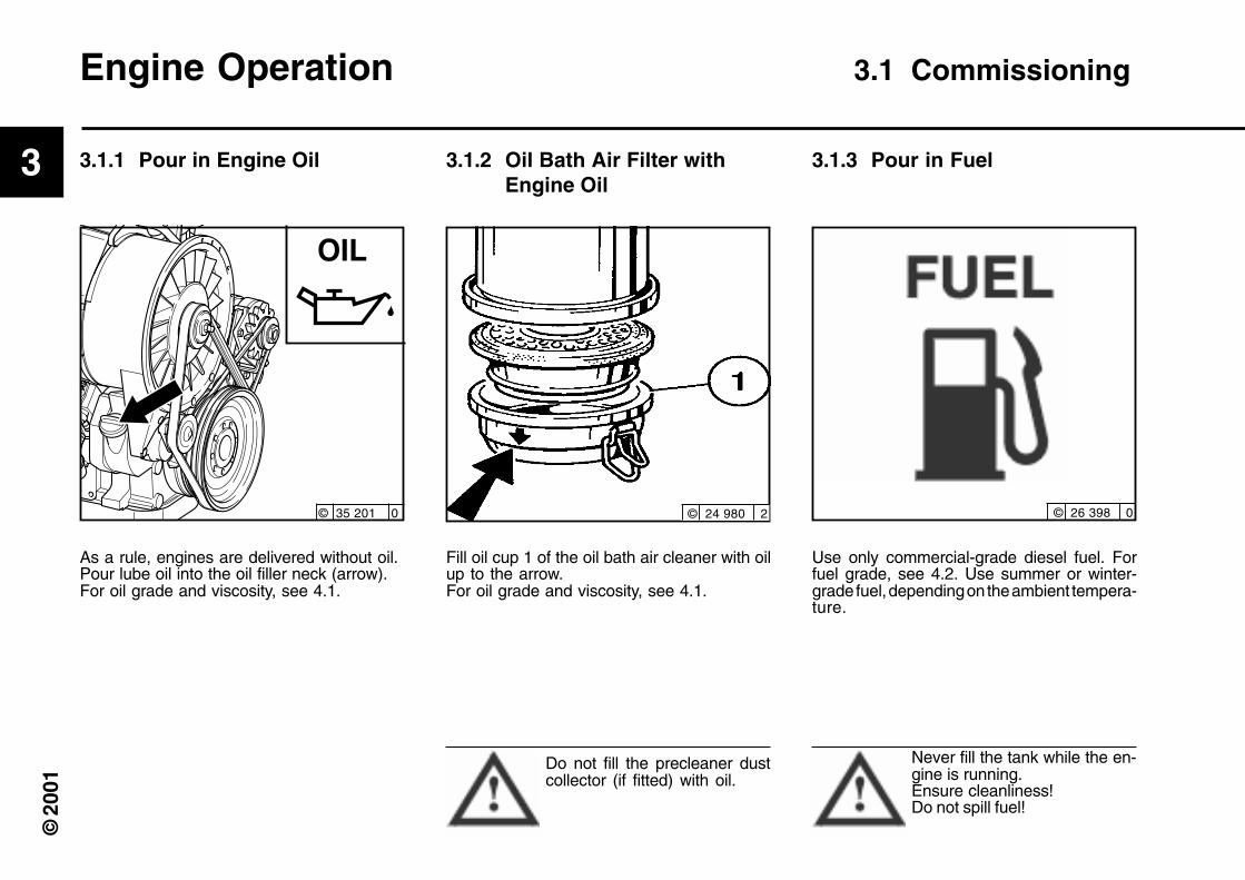
Engine Operation 3.1 Commissioning
Fill oil cup 1 of the oil bath air cleaner with oilup to the arrow.For oil grade and viscosity, see 4.1.
Use only commercial-grade diesel fuel. Forfuel grade, see 4.2. Use summer or winter-grade fuel, depending on the ambient tempera-ture.
Do not fill the precleaner dustcollector (if fitted) with oil.
Never fill the tank while the en-gine is running.Ensure cleanliness!Do not spill fuel!
3.1.1 Pour in Engine Oil 3.1.2 Oil Bath Air Filter withEngine Oil
3.1.3 Pour in Fuel
As a rule, engines are delivered without oil.Pour lube oil into the oil filler neck (arrow).For oil grade and viscosity, see 4.1.
© 24 980 2 © 26 398 0

3
© 2
001
3.1 Commissioning Engine Operation
● Position collecting tank below the injectionpump.
● Unscrew ventilation valve 1 with screw-driver.
● Move hand hump 2 in the direction of thearrow until bubble-free fuel escapes fromthe ventilation valve 1.
● Tighten ventilation valve 1, still pumping.● Remove collecting tank and dispose of the
fuel in an environmentally-friendly manner.
3.1.4 BleedModel:“Motorpal” model
© 35 212 0

3
© 2
001
● Checking battery and cable connectorssee 6.7.1
● Transport hooksRemove if fitted (see 6.7.3)
● Trial runAfter the engine has been prepared, let it runfor about 10 minutes without load.
During and after trial run–Check the engine for leaks.
After the engine has been turned off–Check the oil level, see 6.1.2
If necessary, top up oil, see 3.1.1–Retension V-belts, see 6.5.
● Breaking inDuring the break-in phase, about 200 oper-ating hours, check the oil level twice a day.After the engine is broken in, checking oncea day will be sufficient.
3.1.6 Additional maintenancework
Engine Operation 3.1 Commissioning
After 50-150 operating hours, the followingmaintenance work is to be carried out:
● Change lube oil,see 6.1.2
● Change oil filter cartridge,see 6.1.3
● Change fuel filter cartridge,see 6.2.1
●lCheck V-belts and retension as necessary,see 6.5.
● Check valve clearance (adjust if neces-sary) see 6.6.1
● Check the engine for leaks
● Check engine mounts (retighten if neces-sary) see 9.2.
3.1.5 Other Preparations 3.1.7 Change-over switch for oilheater
Position of change-over switch for oil filterconsoles with an oil heater connected:Pos. 1: openPos. 2: closed
For engines without an oilheater, the change-over switchshould always be fixed to Pos.2: closed.
© 30 027 0

3
© 2
001
3
© 2
001
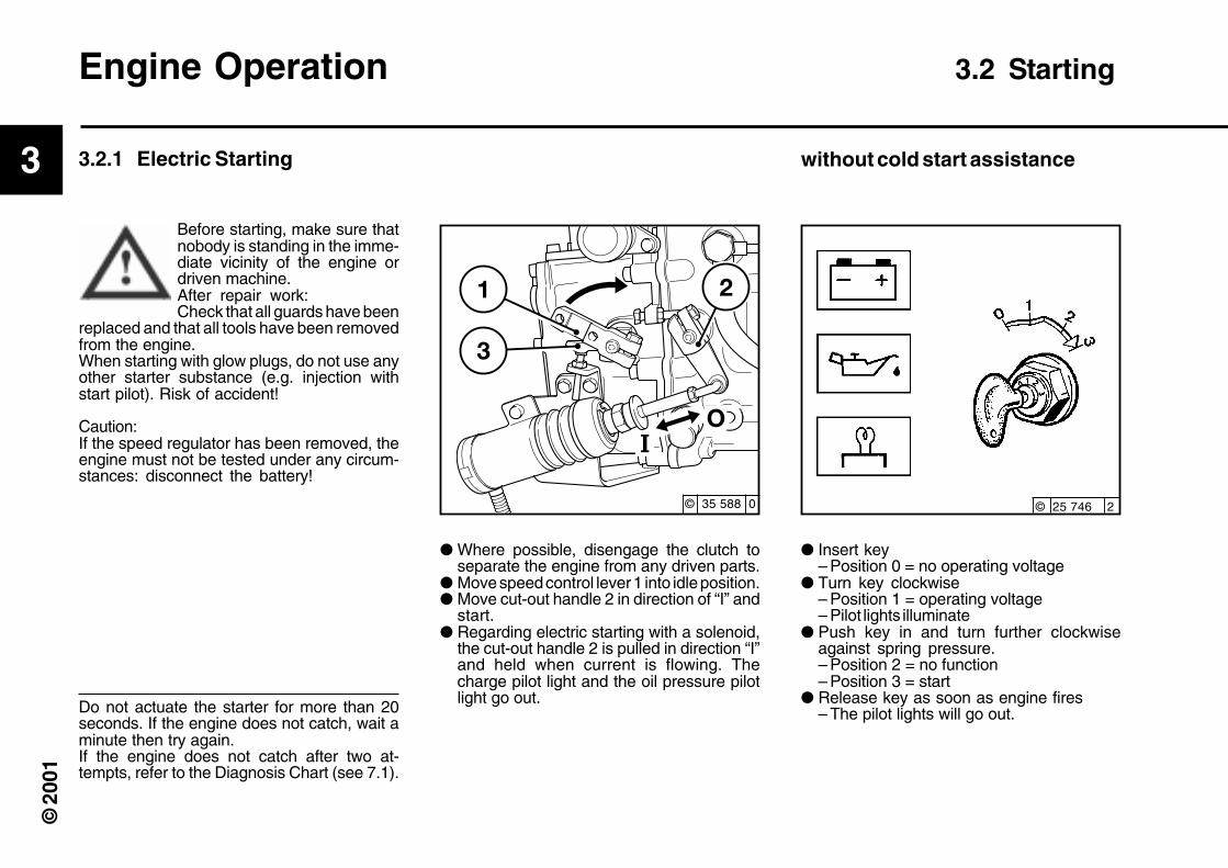
Engine Operation 3.2 Starting
3.2.1 Electric Starting
Before starting, make sure thatnobody is standing in the imme-diate vicinity of the engine ordriven machine.After repair work:Check that all guards have been
replaced and that all tools have been removedfrom the engine.When starting with glow plugs, do not use anyother starter substance (e.g. injection withstart pilot). Risk of accident!
Caution:If the speed regulator has been removed, theengine must not be tested under any circum-stances: disconnect the battery!
Do not actuate the starter for more than 20seconds. If the engine does not catch, wait aminute then try again.If the engine does not catch after two at-tempts, refer to the Diagnosis Chart (see 7.1).
without cold start assistance
● Where possible, disengage the clutch toseparate the engine from any driven parts.
● Move speed control lever 1 into idle position.● Move cut-out handle 2 in direction of “I” and
start.● Regarding electric starting with a solenoid,
the cut-out handle 2 is pulled in direction “I”and held when current is flowing. Thecharge pilot light and the oil pressure pilotlight go out.
● Insert key– Position 0 = no operating voltage
● Turn key clockwise– Position 1 = operating voltage– Pilot lights illuminate
● Push key in and turn further clockwiseagainst spring pressure.– Position 2 = no function– Position 3 = start
● Release key as soon as engine fires– The pilot lights will go out.
© 25 746 2© 35 588 0
3
© 2
001
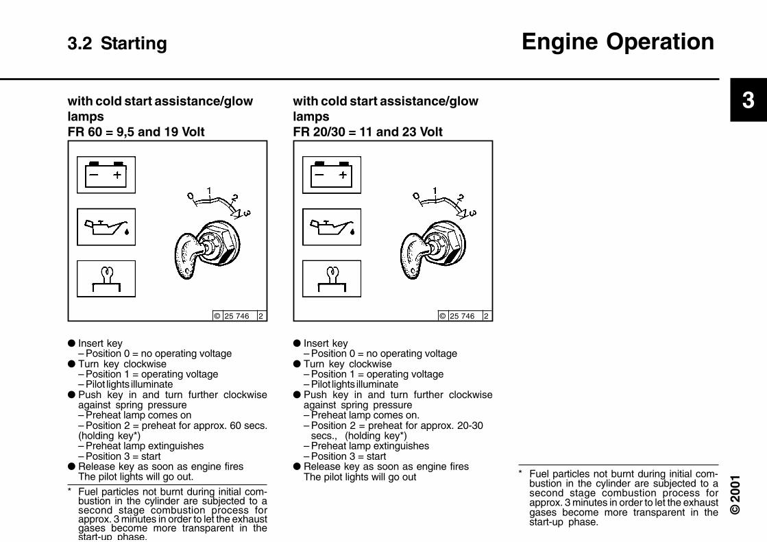
with cold start assistance/glowlampsFR 60 = 9,5 and 19 Volt
● Insert key– Position 0 = no operating voltage
● Turn key clockwise– Position 1 = operating voltage– Pilot lights illuminate
● Push key in and turn further clockwiseagainst spring pressure– Preheat lamp comes on– Position 2 = preheat for approx. 60 secs.(holding key*)– Preheat lamp extinguishes– Position 3 = start
● Release key as soon as engine firesThe pilot lights will go out.
3.2 Starting Engine Operation
with cold start assistance/glowlampsFR 20/30 = 11 and 23 Volt
● Insert key– Position 0 = no operating voltage
● Turn key clockwise– Position 1 = operating voltage– Pilot lights illuminate
● Push key in and turn further clockwiseagainst spring pressure– Preheat lamp comes on.– Position 2 = preheat for approx. 20-30
secs., (holding key*)– Preheat lamp extinguishes– Position 3 = start
● Release key as soon as engine firesThe pilot lights will go out * Fuel particles not burnt during initial com-
bustion in the cylinder are subjected to asecond stage combustion process forapprox. 3 minutes in order to let the exhaustgases become more transparent in thestart-up phase.
* Fuel particles not burnt during initial com-bustion in the cylinder are subjected to asecond stage combustion process forapprox. 3 minutes in order to let the exhaustgases become more transparent in thestart-up phase.
© 25 746 2© 25 746 2

3
© 2
001
Engine Operation 3.3 Monitoring Operation
Oil Pressure Indicator Oil Pressure Gauge
● The oil pressure pilot light comes on withoperating voltage on and engine off.
● The oil pressure pilot light should go outwhen the engine is running.
● The pointer must remain in the green sectorover the entire operating range.
● The pointer of the oil pressure gauge mustdisplay the minimum oil pressure (see 9.1).
3.3.1 Engine Oil Pressure
Oil pressure pilot lights
© 25 752 1 © 25 753 0 © 25 754 0

3
© 2
001
● The engine temperature gauge pointershould remain in the green sector most ofthe time. It should rarely enter the yellow-green sector. If the pointer enters the or-ange sector, the engine is overheating. Turnoff and establish the cause from the FaultTable (see 7.1).
3.3.2 Engine temperature
Engine Temperature Gauge
3.3 Monitoring Operation Engine Operation
● When the V-belt is torn, the pressure pin 1of electrical switch is actuated by the ten-sion roller and an audio signal or a light signalis emitted.Switch off the engine immediately to avoidoverheating.
3.3.3 Cooling fan drive
© 24 985 2 © 24 590 2

3
© 2
001
If possible, do not suddenly switch off theengine when under full load.
● Turn key counterclockwise (to position 0)and remove. The pilot lights will go out.
● Move speed adjustment lever 1 to low idle.● Move shut-off lever 2 in the direction of “0”
until the engine comes to a stop. The chargepilot light and the oil pressure pilot light willcome on when the engine stops.
● Turn key counterclockwise (to position 0)and remove. The pilot lights will go out.
● Concerning electrical shut-off or powerfailure, the shut-off lever 2 is disabled by thesolenoids until the engine stops. The chargepilot light and the oil pressure pilot lightilluminate when the engine stops.
● Turn key counterclockwise (to position 0)and remove. The pilot lights will go out.
Engine Operation 3.4 Shutting Off
3.4.1 Mechanical shut-off 3.4.2 Electrical shut-offIgnition key
© 25 746 2© 35 588 0

3
© 2
001
3.5.1 Winter Operation
● Lube Oil Viscosity– Select the oil viscosity (SAE grade) ac-cording to the ambient temperature whenstarting the engine, see 4.1.2.– Increase oil change frequency whenoperating below -10 °C, see 6.1.1.
● Diesel Fuel– Use winter-grade diesel fuel for operationbelow 0 °C, see 4.2.2
● Additional Maintenance Work– Drain the sludge from the fuel tank once a
week. (Unscrew the sludge drain plug)– If necessary, allow the oil in the oil bath air
cleaner and the engine oil to settle at theambient temperature.
– Below -20 °C, after removing the starter if necessary, smear the ring gear on thefly wheel via the pinion bore from time totime with cold-resistant grease (e.g. BoschFT 1 V 31 grease).
● Cold Start AssistanceAt temperatures near or below freezingpoint, use sheathed glow plugs if neces-sary, see 3.2.1. This not only lowers thestarting limit temperature, but provides easierstarting at temperatures normally not requir-ing a starting aid.
3.5 Operating Conditions Engine Operation
● Battery–Efficient cold starting requires the battery
to be well-charged, see 6.7.1.–The starting limit temperatures can be low-
ered by 4-5 °C by heating the battery up toabout +20 °C. (To do so, remove the batteryand store in a warm place).
© 26 248 2

3
© 2
001
● Air density decreases as altitude or ambienttemperature increase. As a result of this, theengine’s maximum output, the quality of theexhaust gas, the temperature level and, inextreme cases, starting behaviour, are im-peded. Under transient conditions, the en-gine can be used at altitudes up to 1000 mand temperatures up to 30 °C. If the engineis to operate under more severe conditions(at higher altitudes or temperatures), it willbe necessary to reduce the injected fuelquantity and thus, engine power.
● If you have any doubts about engine opera-tion under these or similar conditions, askyour engine or equipment supplier whetherthe engine has been derated in the interestsof reliability, service life and exhaust gasquality (smoke). Otherwise contact DEUTZSERVICE.
Engine Operation 3.5 Operating Conditions
3.5.2 High Ambient Temperature,High Altitude
© 25 901 1

4
© 2
001
Operating Media
4.1 Lube Oil4.2 Fuel

4
© 2
001
Operating Media 4.1 Lube Oil
Lube oils are differentiated according to theirperformance and quality class. In commonuse are specifications named after the API(American Petroleum Institute) and ACEA(European Engine Oil Sequences).
Approved API Oils:At least: CF-4
Approved ACEA Oils:At least: E1-96
It is recommended to operate the engineswith Deutz Oil TLX10W-40FE Europe. Ifthis is not available, use the appropriate oil asdescribed above.
* Oil change intervals, see 6.1.1 Oil capacities, see 9.1
As the viscosity of the lube oil is dependenton temperature, the choice of SAE gradeshould be governed by the ambient tempera-ture prevailing at the engine operating site.Optimum operating behaviour will be attainedif you take the accompanying oil viscositydiagram as a guide.Should the temperature fall temporarily be-low the limits of SAE grade selected, coldstarting may be affected but the engine willnot be damaged. In order to keep wear to aminimum, do not exceed application limits forextended periods of time.Oil changes dictated by the seasons can beavoided by using multi-grade lube oils. Multi-grade oils, particularly light-flowing oils, alsoreduce fuel consumption.
4.1.1 Quality 4.1.2 Viscosity
© 30 298 0Only with engine preheating
4
© 2
001
4.1 Lube Oil Operating Media
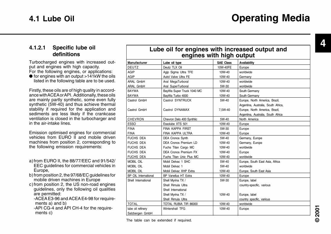
Turbocharged engines with increased out-put and engines with high capacity.For the following engines, or applications:● for engines with an output >141kW the oils
listed in the following table are to be used.
Firstly, these oils are of high quality in accord-ance with ACEA or API. Additionally, these oilsare mainly partly synthetic, some even fullysynthetic (5W-40) and thus achieve thermalstability if required for the application andsediments are less likely if the crankcaseventilation is closed in the turbocharger andin the air-intake lines.
Emission optimised engines for commercialvehicles from EURO II and mobile drivenmachines from position 2, corresponding tothe following emission requirements:
a) from EURO II, the 88/77/EEC and 91/542/EEC guidelines for commercial vehicles inEurope,
b) from position 2, the 97/68/EC guidelines formobile driven machines in Europe
c) from position 2, the US non-road enginesguidelines, only the following oil qualitiesare permitted:-ACEA E3-96 and ACEA E4-98 for require- ments a) and b)-API CG-4 and API CH-4 for the require- ments c)
4.1.2.1 Specific lube oildefinitions
Manufacturer Lube oil type SAE Class AvailabilityDEUTZ Deutz TLX Oil 10W-40FE EuropeAGIP Agip Sigma Ultra TFE 10W-40 worldwideAGIP Autol Valve Ultra FE 10W-40 GermanyARAL GmbH Aral MegaTurboral 10W-40 worldwideARAL GmbH Aral SuperTurboral 5W-30 worldwideBAYWA BayWa Super Truck 1040 MC 10W-40 South GermanyBAYWA BayWa Turbo 4000 10W-40 South GermanyCastrol GmbH Castrol SYNTRUCK 5W-40 Europe, North America, Brazil,
Argentina, Australia, South Africa,Castrol GmbH Castrol DYNAMAX 7,5W-40 Europe, North America, Brazil,
Argentina, Australia, South AfricaCHEVRON Chevron Delo 400 Synthtic 5W-40 North AmericaESSO Essolube XTS 501 10W-40 EuropeFINA FINA KAPPA FIRST 5W-30 EuropeFINA FINA KAPPA ULTRA 10W-40 EuropeFUCHS DEA DEA Cronos Synth 5W-40 Germany, EuropeFUCHS DEA DEA Cronos Premium LD 10W-40 Germany, EuropeFUCHS DEA Fuchs Titan Cargo MC 10W-40 worldwideFUCHS DEA DEA Cronos Premium FX 10W-40 EuropeFUCHS DEA Fuchs Titan Unic Plus MC 10W-40 worldwideMOBIL OIL Mobil Delvac 1 SHC 5W-40 Europe, South East Asia, AfricaMOBIL OIL Mobil Delvac 1 5W-40 worldwideMOBIL OIL Mobil Delvac XHP Extra 10W-40 Europe, South East AsiaBP OIL International BP Vanellus HT Extra 10W-40 EuropeShell International Shell Myrina TX / 5W-30 Europe, label
Shell Rimula Ultra country-specific, variousShell InternationalShell Myrina TX / 10W-40 Europe, labelShell Rimula Ultra country specific, various
TOTAL TOTAL RUBIA TIR 86000 10W-40 worldwidelube oil refinery Wintershall TFG 10W-40 EuropeSalzbergen GmbH
Lube oil for engines with increased output andengines with high output
The table can be extended if required.

4
© 2
001
Use commercially available diesel fuel withless than 0.5 % sulphur content. If the sulphurcontent is higher, oil change intervals shouldbe reduced (see 6.1.1).
The following fuel specifications / standardsare approved: (also see TR 0199-3002)● Diesel fuel
- DIN EN 590- BS 2869: A1 and A2 (with A2, take note of the sulphur content)- ASTM D 975-88; 1-D and 2-D- NATO Code F-54 and F-75- ISO 8217 DMX- ISO 8217 DMA
● Light fuel oilsin accordance with DIN 51603ASTM D 396; 1 and 2BS 2869 Class D
● Jet fuel- F34/F35/F44 (Kerosene)- F54 (corresponds to diesel fuel in accord-ance with DIN EN 590)- XF 63 (corresponds to F34+F35 withadditives)
● Bio diesel fuel- in accordance with DIN 51606- FAME
Exhaust emission values which may bedetermined in the case of type approvaltests always refer to the reference fuelprescribed by the authorities for the typeapproval test.
Waxing may occur at low temperatures,clogging the fuel system and reducing engineefficiency. If the ambient temperature is lessthan 0 °C, winter-grade fuel (suitable downto -20 °C) should be used. (This fuel isavailable from the filling stations well in ad-vance of the cold months).
● Kerosene must be added at temperaturesbelow -20 °C. The relevant percentagesare given in the adjacent diagram.
● Special diesel fuels may be used in arcticclimatic zones up to -44 °C.
If summer-grade diesel fuel must be used attemperatures below 0 °C, up to 60% kero-sene can be added (see diagram).
In most cases, adequate resistance to coldcan be obtained by adding a flow improver(additive). Please ask your DEUTZ partner.
Operating Media 4.2 Fuel
Mix in tank only! Fill with theappropriate amount of kerosenefirst, then add the diesel fuel.
4.2.1 Quality 4.2.2 Winter Fuel
diesel fuel should never be mixedwith petrol (normal or superpetrol)
Legend:
I Summer-grade diesel fuel
II Winter-grade diesel fuel
A Ambient temperature
B Percentage of kerosene added

5
© 2
001
Routine Maintenance
5.1 Maintenance Plan5.2 Maintenance Schedules5.3 Maintenance Work Completed

5
© 2
001
Industrial enginesThe specified engine maintenance values arepermissible recommended maximums. De-pending on usage, reduced maintenance in-tervals may be necessary, comply with the unitmanufacturer’s operating instructions.
# Maintenance must only be carried out byauthorised service personnel
Routine Maintenance 5.1 Maintenance Schedule
check = ● adjust = ❍ clean = ◆ replace = ■
prior to or during 1st trial run, check 2x daily during the breaking in phase or whencommissioning new and overhauled engines
every 10 hours of operation or daily
In hours of operation (HO) every
Operation SectionTop up lube oil if necessary (also with separate container) 6.1.2/3.3.4Lube oil (oil change intervals depending on engine use), see TR 0199-99-3002 6.1.1/6.1.2Oil filter cartridge (at each lube oil change)Oil bath air filter 6.3Bypass – oil filter 6.1.4Fuel filter cartridge #Fuel pre-cleaner 4.2/ 6.2.2Intake air cleaner/dry type air cleaner (If available, maintain according tomaintenance indicator) 6.4.3 /6.4.4Battery and cable connectors 6.7.1Engine monitoring system, warning system 3.3 #Valve clearance (set if necessary, earlier if noises occur) 6.6.1#V-belts (retension or replace if necessary) 6.5.1Sheathed glow lamps 6.9.3Check engine for leaks (visual inspection) –Engine suspension (replace if damaged) 9.2Fastenings, hose connections / clamps 6.9.1Basic overhaul #
E10 E20 E30 E40 E50 E60 E70125 250 500 1000 12000 1 2
● ●
■ ■ ■
■ ■ ■
●
■
■
◆
● ◆
●
●
❍ ❍
● ■
● ■
●
●
●
■
years

5
© 2
001
5.1 Maintenance Schedule Routine Maintenance
Additions and modificationsfor engines with EPA approval
The specified engine maintenance values are permissiblerecommended maximums. Depending on usage, reducedmaintenance intervals may be necessary, comply with theunit manufacturer’s operating instructions.
# Maintenance must only be carried out by authorised service personnel
check = ● adjust = ❍ clean = ◆ replace = ■
max. recommended standard times in operating hours (HO) of allprior to or during 1st trial run, check 2x daily during the breaking in phase or whencommissioning new and overhauled engines
every 10 hours of operation or daily
In hours of operation (HO) every
Operation SectionInjection valve #Intercooler (drain lube oil/condensation) #CPD compressor outlet #Basic overhaul of emission related parts #
E10 E20 E30 E40 E50 E60 E70250 500 1000 2000 3000 4000 1 2
■
◆
◆
■
years

5
© 2
001
Maintenance 5.2 Routine maintenance work plan
Intervals Maintenance Activity Plan executed by: Comments
with/after levels
50 [OH] E 10 after operation and E 50 - E 70 authorised specialised staff
daily E 20 daily inspection the user
250 [OH] E 25 Inspection authorised specialised staff
500 [OH] E 30 further inspection authorised specialised staff
1000 [OH] E 40 intermediate repair authorised specialised staff
3000 [OH] E 50 further intermediate repair authorised specialised staff
6 000 [OH] E 60 partial repair authorised specialised staff
12 000 [OH] E 70 major repair authorised specialised staff
5.2.1 Routine maintenance work plan
5
© 2
001
5.2 Maintenance Charts Routine Maintenance
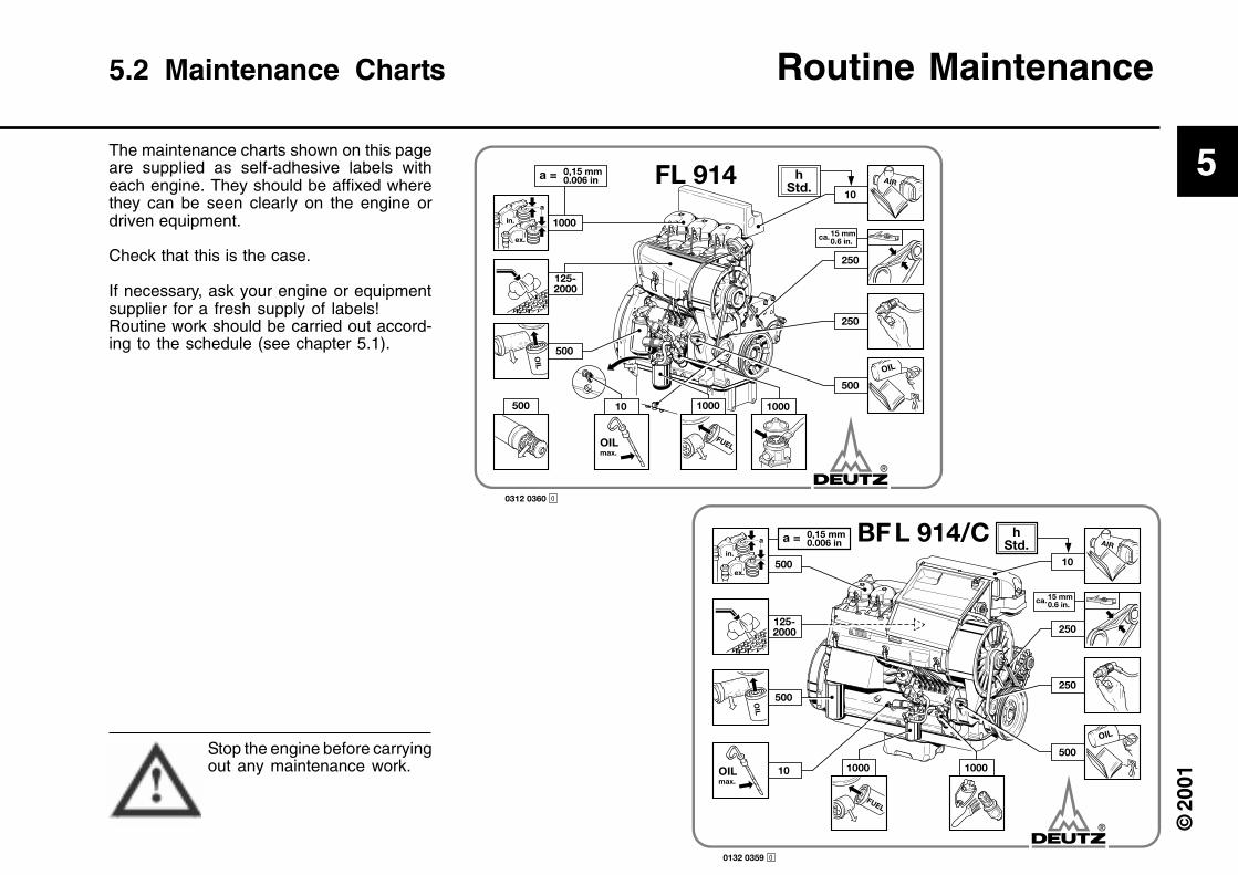
The maintenance charts shown on this pageare supplied as self-adhesive labels witheach engine. They should be affixed wherethey can be seen clearly on the engine ordriven equipment.
Check that this is the case.
If necessary, ask your engine or equipmentsupplier for a fresh supply of labels!Routine work should be carried out accord-ing to the schedule (see chapter 5.1).
Stop the engine before carryingout any maintenance work.
0312 0360 0
hStd.
0,15 mm0.006 ina =
125-2000
1000
FL 914
in.
a
ex.
FUEL
OIL
OIL
AIR
500
1000500
250
500
250
10
1000
OILmax.
10
ca.15 mm0.6 in.
0132 0359 0
10
250
250
500
500
500
10 1000 1000
in.
a
ex.
FUEL
OILmax.
OIL
OIL
AIRh
Std.0,15 mm0.006 ina = BFL 914/C
125-2000
ca.15 mm0.6 in.

5
© 2
001
Routine Maintenance 5.3 Maintenance Work Completed
–
250
500
750
1000
1250
1500
1750
2000
2250
2500
2750
50-150*
125
375
625
875
1125
1375
1625
1875
2115
2375
2625
* following commissioning of new and overhauled engines. Duly completed maintenance jobs can be recorded and signed off in the above chart.
Date Signature/stamp Date Signature/stampOp. hoursOp. hours

5
© 2
001
3000
3250
3500
3750
4000
4250
4500
4750
5000
5250
5500
5750
2875
3125
3375
3625
3875
4125
4375
4625
4875
5125
5375
5625
Duly completed maintenance jobs can be recorded and signed off in the above chart.
Date Signature/stamp Date Signature/stampOp. hoursOp. hours
5.3 Maintenance Work Completed Routine Maintenance

5
© 2
001
Routine Maintenance 5.3 Maintenance Work Completed
6000
6250
6500
6750
7000
7250
7500
7750
8000
8250
8500
8750
5875
6125
6375
6625
6875
7125
7375
7625
7875
8125
8375
8625
Duly completed maintenance jobs can be recorded and signed off in the above chart.
Date Signature/stamp Date Signature/stampOp. hoursOp. hours

5
© 2
001
5.3 Maintenance Work Completed Routine Maintenance

6
Service and Maintenance
6.1 Lubrication System6.2 Fuel System6.3 Cooling system6.4 Combustion Air Filter6.5 Belt Drives6.6 Adjustments6.7 Accessories6.8 Engine cleaning6.9 Additional Maintenance Work

6
Vehicle engines
6.1.1 Oil change intervals
● The oil change intervals are dependent onthe engine application and the quality of thelube oil.
● If the engine runs fewer hours during theyear than stated in the table, the oil shouldbe changed at least once a year.
● The table refers to the following conditions:– For diesel fuel: sulphur content max.
0.5% by weight.– Continuous ambient temperatures down
to -10 °C (+14 °F).
● If the sulphur content is > 0.5 to 1% or thecontinuous ambient temperature belowthe oil change intervals must be halved.
● In the case of fuels with a sulphur contenthigher than 1%, contact your Servicerepresentative.
Change the oil with the engine off but stillwarm (lube oil temperature approx. 80 °C).
Service and Maintenance
Engines for installation
Lube oil quality API specification
ACEA-spezification
Normal oil requirement, e.g.:
Road vehicles, cranes, construction machines,ships electrical modules, pumps, railwayvehicles.
High oil requirement, e.g.:
Combines, emergency pumps, underground miningunits, sweeping machines, winter servicevehicles, emergency power units.
Lube oil quality
Service group
Lube oil change intervals in HONaturally aspirated
engines
CF-4/CH-4/ CG-4 CF-4 CG-4 / CH-4
E1+E2-96 E1+E2-96 E3-96/E4-98
500 250 500
CF-4/CH-4/ CG-4 CF-4 CG-4 / CH-4
E1+E2-96 E1+E2-96 E3-96/E4-98
10 000 5 000 10 000
20 000 10 000 20 000
30 000 15 000 30 000
250 125 250
medium driving speedapprox. km/h
Year’s kilometragekm
API specification
ACEA-spezification
Lube oil change intervals in km
Turbocharged engines
Naturally aspiratedengines Turbocharged engines
I > 30 000 20
II 30.000 -100.000 40
III < 100 000 60

6
6.1 Lubrication System Service and Maintenance
26 023 0 26 022 0 25 729 0
Be careful when draining hot oil - dangerof scalds! Do not let used oil run intothe soil but catch it in a container readyfor proper disposal.
6.1.2 Checking Oil Level /Changing Engine Oil
6.1.2.1 Checking Oil Level 6.1.2.2 Changing Engine Oil
● Run the engine warm● Ensure that the engine or vehicle is on a level
surface– Lube oil temperature approx. 80°C.
● Switch off the engine.
● Place an oil tray beneath the engine● Unscrew drain plug.● Drain oil.● Fit oil drain plug with new gasket and tighten
firmly (for torque, see 9.2).● Fill with lube oil
– For grade/viscosity, see 4.1.– For quantity, see 9.1.
● Check oil level, see 6.1.2.1
● Ensure that the engine or vehicle is on a levelsurface.
● – Warm engine● Switch off engine, wait 5 minutes and check the
oil level● – Cold engine
Check the oil level● Remove the dipstick● Wipe off with a non-fibrous, clean cloth.● Insert up to the stop and pull out again.● Check oil level, if required top up to the
“MAX” level– If the oil level is just above the “MIN” mark,it should be topped up.
!The oil level must not drop below the “MIN” mark.

6
Service and Maintenance 6.1 Lubrication System
6.1.3 Replace Oil Filter
● Clean any dirt from the filter carrier sealingsurface.
● Lightly oil the rubber gasket of the new lubeoil filter cartridge.
● Manually screw in the new cartridge untilthe gasket is flush.
● Tighten the lube oil filter cartridge withanother half-turn.
● Check the oil level, see 6.1.2
● Check oil pressure, see 3.3.1.
● Check lube oil filter cartridge seal for leaks.
● Undo the lube oil filter cartridge using acommercial tool and spin off.
● Catch any escaping oil.
Caution is required in the caseof hot oil: Risk of scalding!Please dispose of oil in anenv i ronmenta l l y - f r i end lymanner!
© 25 881 0© 25 880 0 © 25 882 0

6
6.1 Lubrication System Service and Maintenanceen
6.1.4 Change bypass-oil filteruse
● Remove oil drain screw 1 and let the oil runout.
● Catch any escaping oil.● Remove tensioning screw 2. Remove
cover.● Remove soiled filter 3. Clean filter casing.● Check cover 4 for leaks, and replace if
necessary.● Screw in oil drain screw with a new seal
ring 5.● Insert new filter.● Screw on cover with seal ring 6.● During trial, observe oil pressure and check
for leaks.
© 24 511 1

6
Service and Maintenance 6.2 Fuel System
● Close the fuel shut-off valve.
● Undo fuel filter cartridge with commercialtool and spin off.
● Catch any escaping fuel.
6.2.1 Replace Fuel Filter
● Clean any dirt from the filter carrier sealingsurface.
● Apply light film of oil or diesel fuel to therubber gasket of the new fuel filtercartridge.
● Manually screw in the new cartridge untilthe gasket is flush.
● Tighten the fuel filter cartridge with a finalhalf-turn.
● Open fuel shutoff valve.
● Check for leaks.
Keep naked flames away whenworking on the fuel system. Donot smoke!
The fuel system does not need to bebled.
© 25 881 0© 25 880 0 © 25 882 0

6
6.2 Fuel System Service and Maintenance
● Close the fuel shut-off valve.● Screw out and remove filter cap 4.● Catch any escaping fuel.● Remove strainer 3 and clean with fuel.● Remove seal ring 2.● Clean filter casing 1 with fuel.● Screw on filter cap 4 and strainer 3 with
new seal 2.● Bleed fuel system (see 3.1.4).● Open fuel shutoff valve.● Check for leaks.
6.2.2 Fuel precleaningClean fuel filter“Motorpal” model
Keep naked flames away whenworking on the fuel system. Donot smoke!
© 35 213 0

6
© 2
001
Service and Maintenance 6.3 Cooling System
6.3.1 Cleaning Intervals
● The amount of contamination in the coolingsystem depends on the engine application.
● Oil and fuel residues on the engine in-crease the risk of contamination. There-fore pay special attention to leaks if theengine is used in dusty environments.
● Serious contamination can occur, for ex-ample:- On construction sites where there is a
high level of air-borne dust.- In harvesting application where there are
high concentrations of chaff and choppedstraw in the vicinity of the machine.
● Because applications vary, cleaning inter-vals have to be determined from case tocase. The cleaning intervals given in thetable on the right can be used as a guide.
2000
1000
500
250
125
Checking or cleaning intervals Engine application
Standard values
OH
Ships, electrical modules in enclosed areas, pumps
Vehicles on paved roads
Tractors, fork-lift trucks, drivable electric units.
Vehicles on construction sites and unpaved roads,
construction machines compressors, underground
mining units
Agricultural machines, tractors in harvesting application

6
© 2
001
● The amount of dirt in the air cleaner de-pends on the amount of dust in the air andthe size of the air cleaner used. If a highlevel of dust is anticipated, a cyclone-typeprecleaner can be fitted to the air cleaner.
● Cleaning intervals will have to be deter-mined from case to case.
● If dry type air filters are used, cleaningshould only be carried out according to theservice indicator or service switch.
● Air cleaner servicing is needed when- Service indicator
the red signal 1 is fully visible when theengine is off.
- Service switchthe yellow pilot light comes on when theengine is running.
● After carrying out service work, reset thesignal by pressing the button on the serv-ice indicator. The service indicator is nowready for operation again.
6.4 Combustion Air Filter Service and Maintenance
6.4.1 Cleaning Intervals
© 25 885 1

6
© 2
001
Never fill collector bowl with oil. Replacecollector bowl if damaged.
● Undo wing nut 1 and remove cover 2.● Remove collector bowl 3 from lower sec-
tion 4 and empty. Clean leaves, straw andother foreign matter from lower section ofpre-cleaner.
● Reposition collector bowl 3 onto lowersection 4, fasten cover 2 in place bytightening wing nut 1.
● Turn engine off and wait about 10 minutesfor the oil to drain from filter housing 1.
● Loosen quick fasteners 2 and remove oilcup 3 with filter element 4; if necessary,loosen filter element with the aid of ascrewdriver at the separating point. Do notdamage rubber gasket 5!
● Remove dirty oil and sludge. Clean oil cup.● Clean filter element 4 in diesel fuel and
allow to drip-dry.
● Clean filter housing 1 if very dirty.● Inspect and replace rubber gasket 5 and 6
if necessary.● Fill oil cup with engine oil up to the mark
(arrow) (for viscosity, see 4.1.2).● Refit oil cup and element to filter housing
and secure with snap clips.
Never clean filter with gasoline!Dispose of old oil in accordancewith environmental regulations!
Service and Maintenance 6.4 Combustion Air Filter
6.4.2 Emptying Cyclone TypePrecleaner
6.4.3 Clean Oil Bath Air Filter
© 25 887 0© 25 886 0

6
© 2
001
● Empty dust discharge valve 1 by pressingapart lips of discharge slot as indicated byarrows.
● Clean discharge slot from time to time.● Remove any caked dirt by pressing to-
gether the upper section of the valve.
● Undo clip fasteners 1.● Take off hood 2 and remove cartridge 3.● Clean cartridge (replace at least once a
year).● Clean cartridge 3.
Blow out using dry compressed air (max.5 bar), (or in difficult cases, tap out, takingcare not to damage the cartridge, or washaccording to manufacturer’s instructions).
● Through regular removal and replacement,the gaskets on the filter cartridge canbecome damaged. Check paper filter (lightshowing through) and gaskets for dam-age.Replace if necessary.
Never clean filter cartridge withgasoline or hot fluids.
● After five cleaner services (or after twoyears at the latest), replace safety car-tridge 4 (never clean).To do so:- Undo hex. nut 5 and remove cartridge 4.- Install new cartridge, insert and tighten
hex nut.● Install cartridge 3, replace hood 2 and do up
clip fasteners 1.
6.4 Combustion Air Filter Service and Maintenance
6.4.4 Dry type air cleanerDust discharge valvel Filter Cartridge
© 25 888 1 © 25 889 0
6
© 2
001
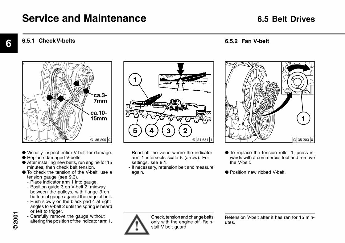
Read off the value where the indicatorarm 1 intersects scale 5 (arrow). Forsettings, see 9.1.
- If necessary, retension belt and measureagain.
Check, tension and change beltsonly with the engine off. Rein-stall V-belt guard
● Visually inspect entire V-belt for damage.● Replace damaged V-belts.● After installing new belts, run engine for 15
minutes, then check belt tension.● To check the tension of the V-belt, use a
tension gauge (see 9.3).- Place indicator arm 1 into gauge.- Position guide 3 on V-belt 2, midway
between the pulleys, with flange 3 onbottom of gauge against the edge of belt.
- Push slowly on the black pad 4 at rightangles to V-belt 2 until the spring is heardor felt to trigger.
- Carefully remove the gauge withoutaltering the position of the indicator arm 1.
Service and Maintenance 6.5 Belt Drives
● To replace the tension roller 1, press in-wards with a commercial tool and removethe V-belt.
● Position new ribbed V-belt.
Retension V-belt after it has ran for 15 min-utes.
6.5.1 Check V-belts 6.5.2 Fan V-belt
© 24 684 1 © 35 203 0© 35 209 0

6
© 2
001
6.5 Belt Drives Service and Maintenance
● Loosen bolts 1, 2 and 3 slightly.
● Press alternator 4 outwards in directionof arrow A until correct belt tension isachieved.
● Retighten bolts 1, 2 and 3.
Check, tension and change beltsonly with the engine off. Rein-stall V-belt guard.
● Remove fan belt, as shown in 6.5.2.● Slacken off bolts 1, 2 and 3.● Swing alternator inwards in the direction
of arrow B.● Remove and replace belt.● Swing alternator 4 outwards in direction
of arrow A until correct belt tension isachieved.
● Retighten bolts 1, 2 and 3.● Fit fan belt.
Retension V-belt after it has ran for 15 min-utes.
● When the V-belt is torn, the pressure pin 1of electrical switch is actuated by thetension roller and an audio signal or a lightsignal is emitted.
● Check the function by pressing pin 1.
Only check function when theengine is off!
6.5.3 Alternator belts 6.5.5 Check warning system6.5.4 Change alternator belt
© 35 207 0 © 35 208 0 © 35 202 0

6
© 2
001
● Unscrew hex screw 1.● Remove outer belt pulley half 2.● Replace V-belt if necessary.
● In order to retension, remove one or moreinner washers 3. Place the removed wash-ers on the outside on the removed beltpulley half 2.
● Tighten screw 1 again. Whilst tightening,turn engine over simultaneously in order toprevent crushing the V-belt.
Service and Maintenance 6.5 Belt Drives
After installing new belts, run engine for 15minutes, then check belt tension.
6.5.6 Tensioningor changing V-belts
© 24 598 1 © 24 599 1

6
© 2
001
● Undo hex nut 1, remove V-belt pulley half2, V-belt 3 and inner washer kit 7.
● Remove inner washers 4, posterior V-belt3, inner washer kit 6 and pulley half 5.
● To retension, remove one or more innerwashers from kits 6 and 7. Place removedwashers in front of or behind pulley half 2to ensure belt alignments. Always removeonly the same number of washers fromeach kit.
● For installation, now proceed in the re-verse order. Whilst tightening the nut 1, turnengine over simultaneously in order toprevent crushing the V-belt.
Check and change belts only with the engineoff.Reinstall V-belt guard, if necessary. RetensionV-belt after it has ran for 15 minutes.
If one belt locks or is damaged, alwaysreplace both belts. The difference of lengthbetween the new belts may not exceed0.15%.
6.5.7 Air compressor model withdual belts
6.5 Belt Drives Service and Maintenance
© 20 762 2
6
© 2
001
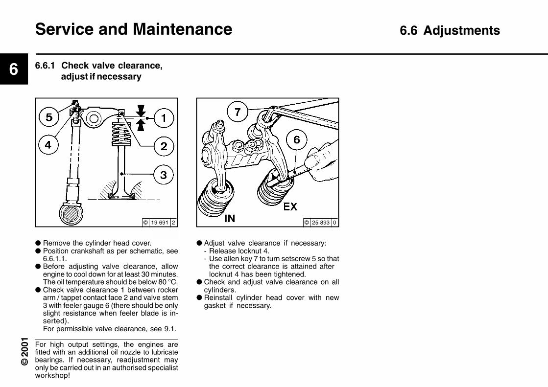
● Remove the cylinder head cover.● Position crankshaft as per schematic, see
6.6.1.1.● Before adjusting valve clearance, allow
engine to cool down for at least 30 minutes.The oil temperature should be below 80 °C.
● Check valve clearance 1 between rockerarm / tappet contact face 2 and valve stem3 with feeler gauge 6 (there should be onlyslight resistance when feeler blade is in-serted).For permissible valve clearance, see 9.1.
For high output settings, the engines arefitted with an additional oil nozzle to lubricatebearings. If necessary, readjustment mayonly be carried out in an authorised specialistworkshop!
● Adjust valve clearance if necessary:- Release locknut 4.- Use allen key 7 to turn setscrew 5 so that
the correct clearance is attained afterlocknut 4 has been tightened.
● Check and adjust valve clearance on allcylinders.
● Reinstall cylinder head cover with newgasket if necessary.
Service and Maintenance 6.6 Adjustments
6.6.1 Check valve clearance,adjust if necessary
© 19 691 2 © 25 893 0
6
© 2
001
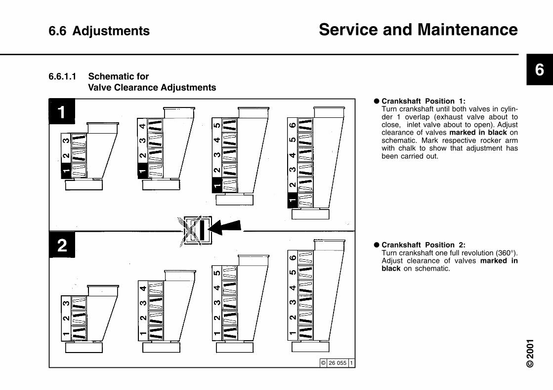
6.6.1.1 Schematic forValve Clearance Adjustments
6.6 Adjustments Service and Maintenance
● Crankshaft Position 2:Turn crankshaft one full revolution (360°).Adjust clearance of valves marked inblack on schematic.
● Crankshaft Position 1:Turn crankshaft until both valves in cylin-der 1 overlap (exhaust valve about toclose, inlet valve about to open). Adjustclearance of valves marked in black onschematic. Mark respective rocker armwith chalk to show that adjustment hasbeen carried out.
© 26 055 1

6
© 2
001
Service and Maintenance 6.7 Accessories
6.7.1.2 Check Electrolyte Level 6.7.1.3 Check electrolytedensity
● Keep battery clean and dry.● Undo dirty clamps.● Clean terminal posts (+ and -) and clamps
of the battery, and grease with acid-freeand acid-resistant grease.
● When reassembling, ensure that clampsmake good contact. Tighten clamp boltshand-tight.
● Remove sealing caps 1.● If testers 2 are present: Electrolyte level
should reach the base of these.● Without testers:
The electrolyte level should be 10-15 mmabove the top of the plates.
● If necessary, top up with distilled water.● Screw sealing caps back in.
● Measure the electrolyte density of indi-vidual cells with a commercial hydrometer.
The hydrometer reading (see table on fol-lowing page) indicates the battery’s stateof charge.During measurement, the temperature ofthe electrolyte should preferably be +20 °C.
6.7.1 Battery6.7.1.1 Checking battery and
cable connectors
© 25 895 0 © 24 232 3 © 25 896 0

6
© 2
001
6.7 Accessories Service and Maintenance
* Measurement of electrolyte density in ° Bé(Baumé-scale) is out of date and rarelyused today.
The gases emitted by the bat-tery are explosive! Keep sparksand naked flames away fromthe battery! Do not allow batteryacid to come into contact with
skin or clothing! Wear protective goggles! Donot rest tools on the battery!
in [kg/ l] in [°Bé (Baumé scale)*] Charge status
Normal Tropical Normal Tropical
1,28 1,23 32 27 well charged
1,20 1,12 24 16 semi-charged, re-charge
1,12 1,08 16 11 discharged, immediately charge
6
© 2
001
Notes on the three-phase system:● Never disconnect the cables between
battery, alternator and regulator while theengine is running.
● If, however, it is necessary to start andoperate the engine without the battery,disconnect the regulator from the alterna-tor before starting.
● Be sure not to confuse the battery termi-nals.
● Replace defective charge pilot lamp bulbimmediately.
● When washing the engine, cover up thealternator and regulator.
● The habit of touching a lead against theframe to check whether it is live must underno circumstances be exercised with three-phase electrical systems.
● In case of electric welding, connect theground terminal on the welder directly tothe piece being welded.
Service and Maintenance 6.7 Accessories
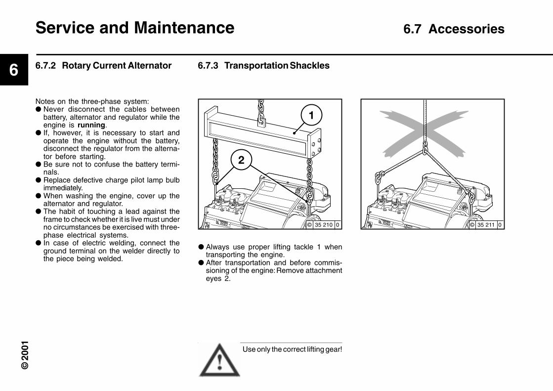
6.7.2 Rotary Current Alternator 6.7.3 Transportation Shackles
● Always use proper lifting tackle 1 whentransporting the engine.
● After transportation and before commis-sioning of the engine:Remove attachmenteyes 2.
Use only the correct lifting gear!
© 35 210 0 © 35 211 0
6
© 2
001
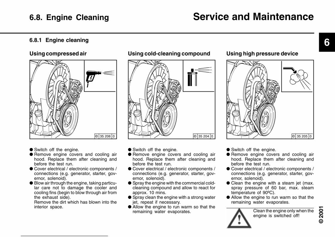
6.8. Engine Cleaning Service and Maintenance
6.8.1 Engine cleaning
Using compressed air
● Switch off the engine.● Remove engine covers and cooling air
hood. Replace them after cleaning andbefore the test run.
● Cover electrical / electronic components /connections (e.g. generator, starter, gov-ernor, solenoid).
● Blow air through the engine, taking particu-lar care not to damage the cooler andcooling fins (begin to blow through air fromthe exhaust side).Remove the dirt which has blown into theinterior space.
Using cold-cleaning compound
● Switch off the engine.● Remove engine covers and cooling air
hood. Replace them after cleaning andbefore the test run.
● Cover electrical / electronic components /connections (e.g. generator, starter, gov-ernor, solenoid).
● Spray the engine with the commercial cold-cleaning compound and allow to react forapprox. 10 mins.
● Spray clean the engine with a strong waterjet, repeat if necessary.
● Allow the engine to run warm so that theremaining water evaporates.
Using high pressure device
● Switch off the engine.● Remove engine covers and cooling air
hood. Replace them after cleaning andbefore the test run.
● Cover electrical / electronic components /connections (e.g. generator, starter, gov-ernor, solenoid).
● Clean the engine with a steam jet (max.spray pressure of 60 bar, max. steamtemperature of 90ºC).
● Allow the engine to run warm so that theremaining water evaporates.
Clean the engine only when theengine is switched off!
© 35 206 0 © 35 204 0 © 35 205 0
6
© 2
001
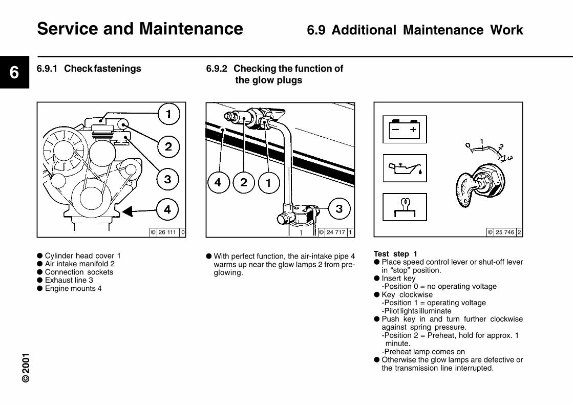
Service and Maintenance 6.9 Additional Maintenance Work
● Cylinder head cover 1● Air intake manifold 2● Connection sockets● Exhaust line 3● Engine mounts 4
● With perfect function, the air-intake pipe 4warms up near the glow lamps 2 from pre-glowing.
Test step 1● Place speed control lever or shut-off lever
in “stop” position.● Insert key
-Position 0 = no operating voltage● Key clockwise
-Position 1 = operating voltage-Pilot lights illuminate
● Push key in and turn further clockwiseagainst spring pressure.-Position 2 = Preheat, hold for approx. 1 minute.-Preheat lamp comes on
● Otherwise the glow lamps are defective orthe transmission line interrupted.
6.9.1 Check fastenings 6.9.2 Checking the function of the glow plugs
© 26 111 0 © 24 717 1 © 25 746 2

6
© 2
001
6.9 Additional Maintenance Work Service and Maintenance
Test step 2● Loosen screw 1.● Turn engine over with starter, key in switch-
ing position 3.● Fuel must be present on the loosened pipe
connection. Otherwise, the system andsolenoid valve should be checked by aspecialist!
Test step 3● Loosen screw 1.● Remove glow lamps 2● Turn engine over with starter, key in switch-
ing position 3.● Fuel must be present on the glow lamps 2,
or replace glow lamps 2 if necessary.● When fitting glow lamps 2, use DEUTZ DW
47 sealants.● Reinstall glow lamps to fuel line.
Keep away from moving parts!Collect any escaping fuel anddispose of this in an environ-mentally-friendly manner.
© 24 717 1 © 24 717 1

6
© 2
001
7
© 2
001
Faults, Causes and Remedies
7.1 Fault Table
7
© 2
001
Faults, Causes and Remedies 7.1 Fault Table
●
● ●
● ●
● ●
● ● ● ●
● ● ●
● ●
● ● ● ● ● ●
● ● ●
●
● ● ●
● ●
●
● ● ●
● ●
●
●
●
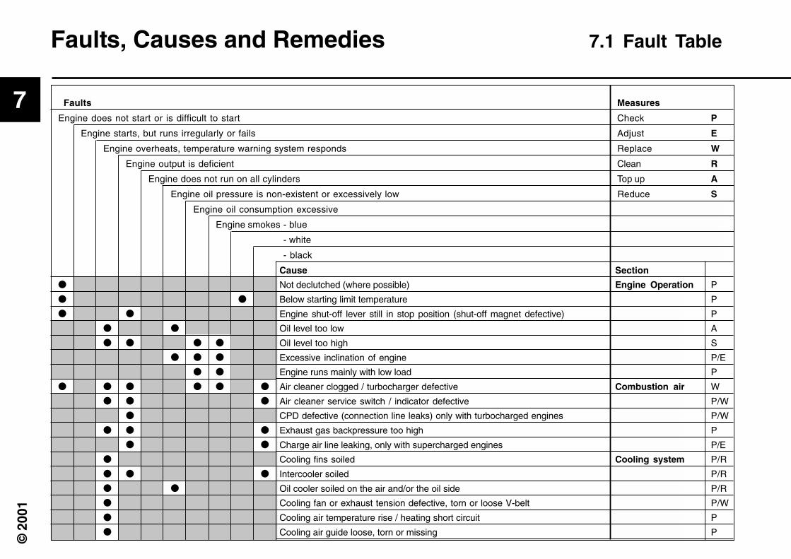
Cause Section
Not declutched (where possible) Engine Operation P
Below starting limit temperature P
Engine shut-off lever still in stop position (shut-off magnet defective) P
Oil level too low A
Oil level too high S
Excessive inclination of engine P/E
Engine runs mainly with low load P
Air cleaner clogged / turbocharger defective Combustion air W
Air cleaner service switch / indicator defective P/W
CPD defective (connection line leaks) only with turbocharged engines P/W
Exhaust gas backpressure too high P
Charge air line leaking, only with supercharged engines P/E
Cooling fins soiled Cooling system P/R
Intercooler soiled P/R
Oil cooler soiled on the air and/or the oil side P/R
Cooling fan or exhaust tension defective, torn or loose V-belt P/W
Cooling air temperature rise / heating short circuit P
Cooling air guide loose, torn or missing P
Faults Measures
Engine does not start or is difficult to start Check P
Engine starts, but runs irregularly or fails Adjust E
Engine overheats, temperature warning system responds Replace W
Engine output is deficient Clean R
Engine does not run on all cylinders Top up A
Engine oil pressure is non-existent or excessively low Reduce S
Engine oil consumption excessive
Engine smokes - blue
- white
- black

7
© 2
001
●
●
●
●
● ● ● ● ● ● ●
● ● ● ●
●
● ● ●
● ● ● ● ● ● ●
● ● ● ●
● ● ● ●
● ●
● ● ●
● ● ● ● ● ●
●
7.1 Fault Table Faults, Causes and Remedies
Faults Measures
Engine does not start or is difficult to start Check P
Engine starts, but runs irregularly or fails Adjust E
Engine overheats, temperature warning system responds Replace W
Engine output is deficient Clean R
Engine does not run on all cylinders Top up A
Engine oil pressure is non-existent or excessively low Reduce S
Engine oil consumption excessive
Engine smokes - blue
- white
- black
Cause Section
Battery defective or discharged Electrics P
Cable connections, starter, electrical circuit loose or oxidised P
Starter defective or pinion does not engage P
Oil pressure switch / gauge defective P/W
Incorrect valve clearance Engine P/E
Injection line leaks P/R
Ventilation line blocked P/R
Glow plugs P/W
Injection valve defective P/W
Air in the fuel system P/W
Fuel filter / fuel pre-cleaner soiled P/R/W
Oil filter defective W
Incorrect engine lube oil SAE class or quality W
Compression too low P
Oil in combustion chamber P/R

7
© 2
001

8
© 2
001
Engine Preservation
8.1 Preservation

8
© 2
001
If the engine is to remain idle for an extendedperiod of time, it is necessary to take protec-tive measures to prevent the formation ofcorrosion. The preservative measures de-scribed here will protect the engine for up toapprox. 6 months. The procedure will have tobe reversed before the engine isrecommissioned
● Anti-corrosion oils to specification:- MIL-L 21260B- TL 9150-037/2- Nato Code C 640 / 642
● Recommended cleaning agent to removepreservatives:- Petroleum benzine (hazardous materialsclass A3)
Engine Preservation 8.1 Preservation
● Remove anti-corrosion agent from groovesin V-belt pulleys.
● Install V-belt, retension after brief opera-tion if necessary (see 6.5).
● Remove covers from intake port and ex-haust ports.
● Commission engine.
8.1 Preservation8.1.1 Preserve engine 8.1.2 Remove engine
preservation
● Clean engine (with cold cleansing agent ifpreferred) using high pressure equipment(see 6.8.1).
● Run engine until warm, then turn off.● Drain engine oil, (see 6.1.2), and fill with
anti-corrosion oil.● If necessary, clean oil bath cleaner (see
6.4.3), and fill with anti-corrosion oil.● Drain fuel tank.● Make up a mixture of 90 % diesel fuel and
10 % anti-corrosion oil, and refill fuel tank.● Allow the engine to run for approx. 10 mins.● Switch off the engine.● Turn engine over manually several times to
preserve the cylinders and combustionchamber.When turning over with starter, set shut-off lever to stop position.
● Remove V-belts and store wrapped, dryand recumbent.
● Spray grooves on V-belt pulleys with anti-corrosion spray.
● Close off intake ports and exhaust ports,possibly with plugs.

9
© 2
001
Technical Specification
9.1 Engine Specifications and Settings9.2 Screw Tightening Torques9.3 Tools

9
© 2
001
Technical Specification 9.1 Engine Specifications and Settings
ModelNumber of cylindersCylinder arrangementBore [mm]Stroke [mm]Total displacement [cm3]Compression ratio [ε]Working cycleCombustion systemDirection of rotation seen on flywheelWeight including cooling system to DIN 70020-Awithout starter or alternator [approx. kg]Engine output [kW]Speed [rpm]LubricationSAE oilOil temperature in oil pan [°C]Min. oil pressure when warm (120 °C)and low idle [bar]ÖOil plate filling quantity without filter [approx. litres]Oil plate filling quantity with filter [approx. litres]Valve clearance with cold engine [mm]Injector opening pressure [bar]Start of feed [°KW of TDC]Firing order of the engineV-Belt tension:Alternator fan [N]Compressor [N]
F3L 914 F4L 914 F5L 914 F6L 9143 4 5 6
vertical in line102132
3236 4314 5393 647220
4-stroke naturally aspirated diesel engine Direct injection
counter-clockwise
270 5) 300 5) 380 5) 410 5)
1)1)
Pressure lubrication15W 40
135
0,4 4)
9,0 3) 12,0 3) 13,5 3) 14,5 3)
9,6 3) 13,0 3) 15,0 3) 16,0 3)
Inlet 0,15 + 0,05 / exhaust 0,15 + 0,05200 + 10
1)1–2–3 1–3–4–2 1–2–4–5–3 1–5–3–6–2–4
Pre-tension / re-tension 2)
450 / 300 ± 20550 / 400 ± 20
1) Engine output, speed, start of delivery are stamped on engine rating plate, etc., (see also 2.1).2) Re-tension 15 minutes after the engine has been operated under load.3) Approx. values may vary depending on version. The upper oil dipstick mark is always authoritative.4) Values for engines without engine oil heating.5) Approx. values may vary depending on version.

9
© 2
001
9.1 Engine Specifications and Settings Technical Specification
BF3L 914 BF4L 914 BF6L 914 BF6L 914 C3 4 6 6
vertical in line102132
3236 4314 6472 647218
4-stroke turbocharged diesel engine Direct injection
counter-clockwise
320 5) 360 5) 485 5) 510 5)
1)1)
Pressure lubrication15W 40
135
0,5 4)
9 3) 12 3) 16,0 3) 16,0 3)
9,6 3) 13 3) 17,5 3) 17,5 3)
Inlet 0,15 + 0,05 / exhaust 0,15 + 0,05200 + 10
1)1–2–3 1–3–4–2 1–5–3–6–2–4 1–5–3–6–2–4
Pretension / Retension 2)
400 / 250 ± 20500 / 350 ± 20
914/C/CT ModelNumber of cylindersCylinder arrangementBore[mm]Stroke[mm]Total displacement [cm3]Compression ratio [ε]Working cycleCombustion systemDirection of rotation seen on flywheelWeight including cooling system to DIN 70020-Awithout starter or alternator [approx. kg]Engine output [kW]Speed [rpm]LubricationSAE oilOil temperature in oil pan [°C]Min. oil pressure when warm (120 °C)and low idle [bar]Oil plate filling quantity without filter [approx. litres]Oil plate filling quantity with filter [approx. litres]Valve clearance with cold engine [mm]Injector opening pressure [bar]Start of feed [°KW of TDC]Firing order of the engineV-Belt tension: Pretension / RetensionAlternator fan [N]Compressor [N]
1) Engine output, speed, start of delivery are stamped on engine rating plate, etc., (see also 2.1).2) Re-tension 15 minutes after the engine has been operated under load.3) Approx. values may vary depending on version. The upper oil dipstick mark is always authoritative.4) Values for engines without engine oil heating.5) Approx. values may vary depending on version.

9
© 2
001
Technical Specification 9.2 Torque Wrench Settings
Installation Pretension Retension Total Comments
[Nm] 1st position 2nd position 3rd position 4th position
Securing the alternator 20 180° – – – 180° M10 x 18030 180° – – – 180° M14 x 230
Cylinder head cover – – – – – 12 ± 1,2 Nm –
Valve clearance adjusting screw – – – – – 22 ± 2 Nm –Foot 30 60° 15° – – 75° M14 x 100
30 60° 45° – – 105° M14 x 110
30 60° 45° – – 105° M14 x 125
Intake manifold – – – – – 21 ± 2 Nm –
Exhaust manifold – – – – – 40 ± 4 Nm –
Oil drain screw – – – – – 150 ± 10 Nm M30 x 1,5Oil drain screw – – – – – 80 ± 10 Nm M22 x 1,5
Injection valve attachment – – – – – 25–30 Nm –

9
© 2
001
9.3 Tools Technical Specification
V-belt tension gauge
The V-belt tension gauge can be obtainedunder order number 8115 from:
WILBÄRPostfach 14 05 80D-42826 Remscheid
© 26 002 0

10
Service
Knowing it’s DEUTZ
DEUTZ has always stood for excellence in motorconstruction, pioneering many developments inthe industry. As an independent motor manu-facturer, we offer — worldwide — a com-prehensive range of diesel and gas motorsspanning from 4kW to 7,400kW. Our products areperfectly tailored to meet our customers’ individualrequirements.
Over 1.4 million DEUTZ motors do their jobreliably all over the world. We are determined topreserve the high standard of performance anddependability of our motors, thus keeping ourcustomers satisfied at all times. Therefore we arerepresented worldwide through a network of highlycompetent service partners who will meet theneeds of our customers, wherever they are.
This is why DEUTZ is not only the name for motorswhich pack a lot of inventive genius. DEUTZ alsomeans reliable service and comprehensive supportto enhance your motor’s performance.
This index Sales & Service offers you an overviewof the DEUTZ partners in your vicinity, including theproducts for which they are responsible and therange of services provided. But even when no directproduct responsibility is mentioned, your DEUTZpartner will be happy to help you with expert advice.
The Index is constantly updated. Please ask yourDEUTZ service partner for the latest edition.
DEUTZ AG — at your service.
Order-No.: 0312 0806
Order-No.: 0312 0807 (CD-ROM)
DEUTZ AGDeutz-Mülheimer Str. 147-149D-51057 Köln
Phone: 0049-221-822-0Telefax: 0049-221-822-5304Telex: 8812-0 khd dhttp://www.deutz.de
Obtainable from the local service Partner reponsiblefor you or from:
en

Imprint:
DEUTZ AG
Service-Technik
Instandhaltungstechnik Motoren
Deutz-Mülheimer Straße 147-149
D - 51057 Köln
Telefon: 0221 - 822 - 0
Fax: 0221 - 822 - 5358
http://www.deutz.de
Printed in Germany
Allrights reserved
1st edition, 01/2002 ©
Order no. 0312 0382 en