Embed Size (px)
DESCRIPTION
solid control
Citation preview

5/21/2010
1
SCOMI OILTOOLS
Solids ControlSolids ControlEquipmentEquipment
Solids ControlSolids ControlEquipmentEquipment
Global Research & Technology Centre/ GRTC
Training Department
SCOMI OILTOOLS
Drilling out hole with bit and generate cuttings
The mud brings the cutting up to surface
At surface, cutting will be separated out from mud.
Cutting will be discarded
Drilling and Making Hole

5/21/2010
2
SCOMI OILTOOLS
Drilling and Making Hole
At surface, cutting will be separated out from mud.
Cutting will be discarded
SOLID CONTROL
MUDMUD
CUTTINGS CUTTINGS discardeddiscardedWASTEWASTE
SCOMI OILTOOLS
What is mud
LIQUID MUDSOLIDS
WATER
OIL
SALT
CHEMICALS
BARITE
BENTONITE/GEL
DRILL SOLIDS
WATER-BASE MUD
OIL-BASE MUD
5/21/2010
3
SCOMI OILTOOLS
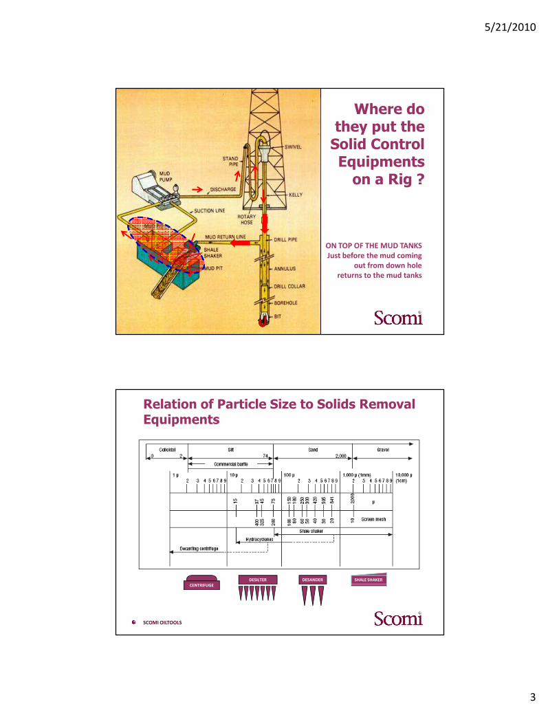
Where do they put the Solid Control Equipments on a Rig ?
ON TOP OF THE MUD TANKS
Just before the mud coming
out from down hole
returns to the mud tanks
SCOMI OILTOOLS
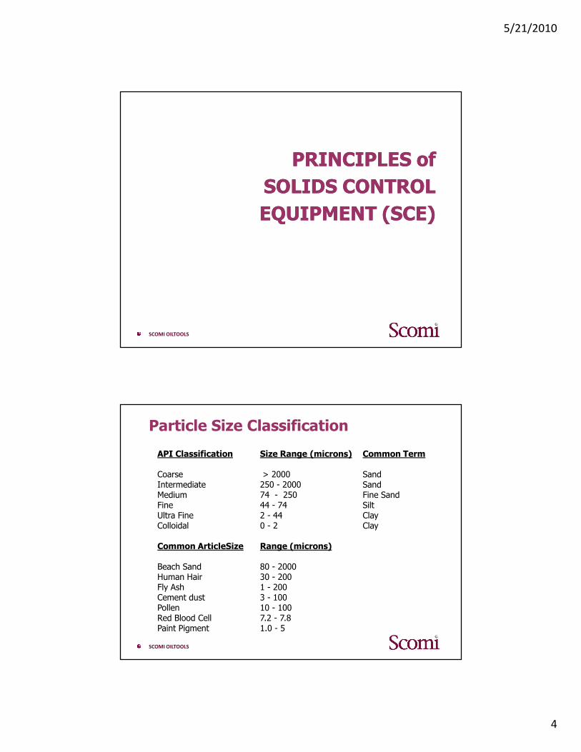
Relation of Particle Size to Solids Removal Equipments
SHALE SHAKERDESANDERDESILTER
CENTRIFUGE
5/21/2010
4
SCOMI OILTOOLS
PRINCIPLES of PRINCIPLES of
SOLIDS CONTROL SOLIDS CONTROL
EQUIPMENT (SCE)EQUIPMENT (SCE)
SCOMI OILTOOLS
Particle Size Classification
API Classification Size Range (microns) Common Term
Coarse > 2000 SandIntermediate 250 - 2000 SandMedium 74 - 250 Fine SandFine 44 - 74 SiltUltra Fine 2 - 44 ClayColloidal 0 - 2 Clay
Common ArticleSize Range (microns)
Beach Sand 80 - 2000Human Hair 30 - 200Fly Ash 1 - 200Cement dust 3 - 100Pollen 10 - 100Red Blood Cell 7.2 - 7.8Paint Pigment 1.0 - 5
5/21/2010
5
SCOMI OILTOOLS
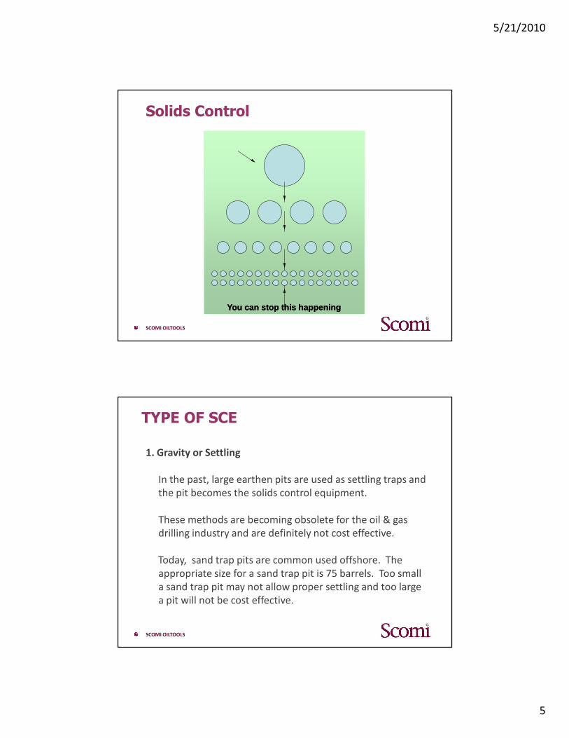
Solids Control
You can stop this happeningYou can stop this happening
SCOMI OILTOOLS
TYPE OF SCE
1. Gravity or Settling
In the past, large earthen pits are used as settling traps and
the pit becomes the solids control equipment.
These methods are becoming obsolete for the oil & gas
drilling industry and are definitely not cost effective.
Today, sand trap pits are common used offshore. The
appropriate size for a sand trap pit is 75 barrels. Too small
a sand trap pit may not allow proper settling and too large
a pit will not be cost effective.

5/21/2010
6
SCOMI OILTOOLS
TYPE OF SCE
2. Dilution
A common method of trying to offset the build-up of
drilled solids is the addition of more liquid to the system.
This is dilution and does not remove cuttings but instead
reduces (or dilutes) their concentration in a drilling mud,
thereby reducing the presence of total solids in the mud.
It is important to note that dilution is expensive.
Dilution, for every 1bbl of solids introduced to the mud, 20
bbls of fresh fluid is required to return the drilling fluid to
the correct concentration (At 5% Solids) ©
SCOMI OILTOOLS
TYPE OF SCE
3. Solids Removal Equipment
Solids removal by mechanical separation can achieve the
benefits of low solids content and at the same time
significantly reduce the many costs associated with
dilution. The primary types of solids removal equipment
include:
• Shale Shaker
• De-sanders, De-silters (Hydro-cyclones)
• Mud Cleaners
• Centrifuges.
5/21/2010
7
SCOMI OILTOOLS
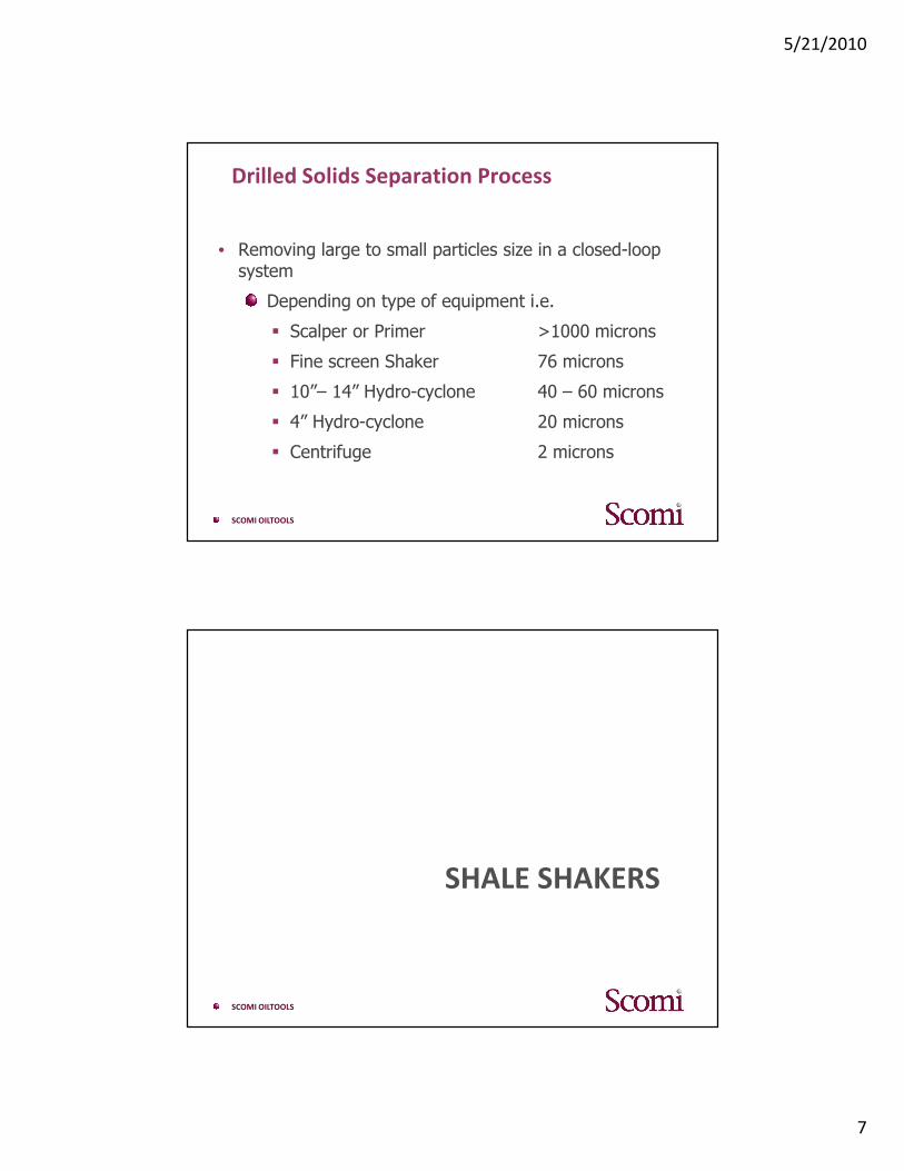
Drilled Solids Separation Process
• Removing large to small particles size in a closed-loop system
Depending on type of equipment i.e.
� Scalper or Primer >1000 microns
� Fine screen Shaker 76 microns
� 10”– 14” Hydro-cyclone 40 – 60 microns
� 4” Hydro-cyclone 20 microns
� Centrifuge 2 microns
SCOMI OILTOOLS
SHALE SHAKERS

5/21/2010
8
SCOMI OILTOOLS
SHALE SHAKERS
If shakers are not used effectively - other SCE downstream will not perform properly
SCOMI OILTOOLS
SHALE SHAKERS
� The first and most effective (in volume terms) ofremoving solids.
� Usually 60 -80% efficient at removing the solidsthat have been drilled.
� All shale shakers rely on screening of the drillingfluid through a vibratory surface. The number andmotion of the vibratory surface varies from onemanufacturer to another.
5/21/2010
9
SCOMI OILTOOLS
SHALE SHAKERS
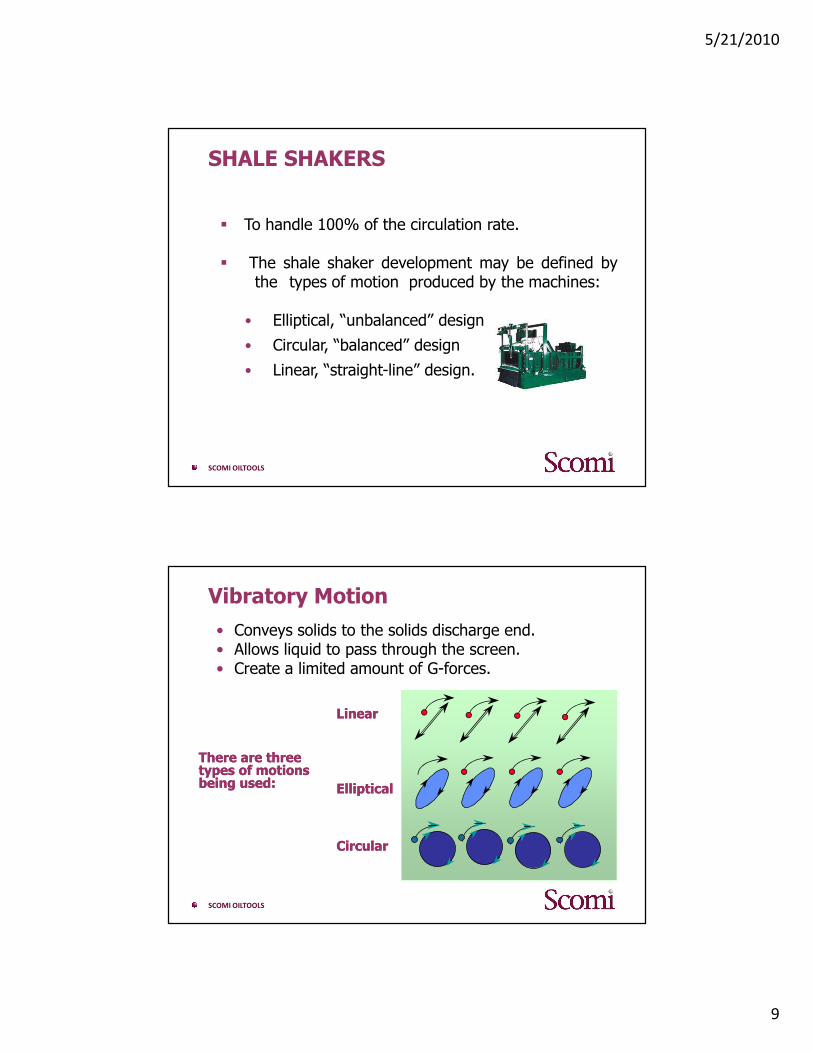
� To handle 100% of the circulation rate.
� The shale shaker development may be defined bythe types of motion produced by the machines:
• Elliptical, “unbalanced” design
• Circular, “balanced” design
• Linear, “straight-line” design.
SCOMI OILTOOLS
Vibratory Motion
• Conveys solids to the solids discharge end.• Allows liquid to pass through the screen.• Create a limited amount of G-forces.
LinearLinear
EllipticalElliptical
CircularCircular
There are three There are three types of motions types of motions being used:being used:

5/21/2010
10
SCOMI OILTOOLS
SHALE SHAKERS
Design performance of shakers are defined by:
• Type of Motion
• Stroke length
• Rpm of vibrator
Vibration motion along the deck depends on:
• Position of the vibrator/motor
• Direction of rotation
SCOMI OILTOOLS
Shale Shakers Motions Shale Shakers Motions –– EllipticalElliptical
If a vibrator is mounted abovethe deck the motion is:
● elliptical at the ends of thedeck
● circular below the vibrator.
The rate of travel of the solidsis controlled by:
● the axis of the ellipse,● slope of the screens,● and direction of rotation.

5/21/2010
11
SCOMI OILTOOLS
Shale Shakers Motions Shale Shakers Motions –– EllipticalElliptical
• The elliptical shaker requires adownward slope basket to properlytransport cuttings across thescreen and off the discharge end.
• This reduces fluid retention timeand limits the capacity of thisdesign.
• Optimum screening with thesetypes of shakers is usually in the30-40 mesh (400-600 micron)range.
SCOMI OILTOOLS
Shale Shakers Motions Shale Shakers Motions –– CircularCircular
• If the vibrator is mounted close to the screens and center of gravity, the motion is circular.
• Cuttings travel direction and speed on a horizontal deck depends on the• direction of rotation,• the frequency of vibration • the amplitude of motion.
The circular motion shaker was introduced in the late 1960s and early 1970s.
• Amplitude of motion is the distance from the mean position of themotion to the point of maximum displacement. For a circular motion,the amplitude is the radius of a point on the screen deck side. Thestroke is the total movement or twice the amplitude
5/21/2010
12
SCOMI OILTOOLS
Shale Shakers Motions Shale Shakers Motions –– CircularCircular
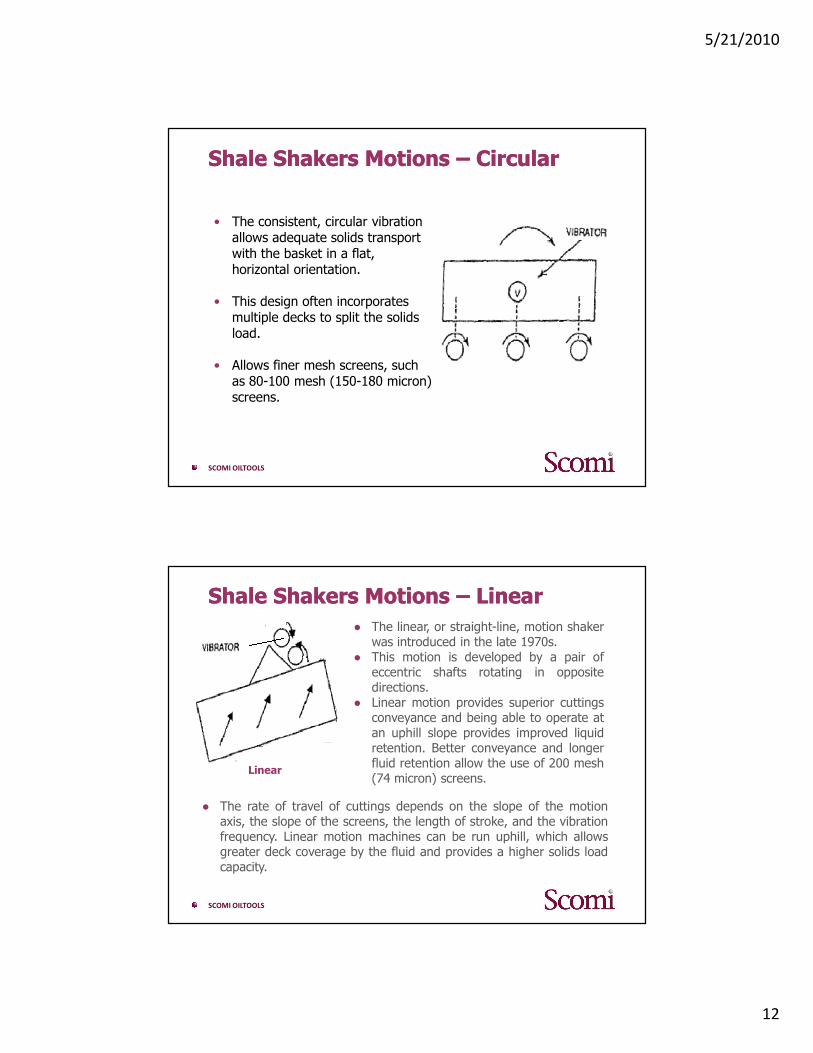
• The consistent, circular vibration allows adequate solids transport with the basket in a flat, horizontal orientation.
• This design often incorporates multiple decks to split the solids load.
• Allows finer mesh screens, such as 80-100 mesh (150-180 micron) screens.
SCOMI OILTOOLS
Shale Shakers Motions Shale Shakers Motions –– LinearLinear
Linear
● The linear, or straight-line, motion shakerwas introduced in the late 1970s.
● This motion is developed by a pair ofeccentric shafts rotating in oppositedirections.
● Linear motion provides superior cuttingsconveyance and being able to operate atan uphill slope provides improved liquidretention. Better conveyance and longerfluid retention allow the use of 200 mesh(74 micron) screens.
● The rate of travel of cuttings depends on the slope of the motionaxis, the slope of the screens, the length of stroke, and the vibrationfrequency. Linear motion machines can be run uphill, which allowsgreater deck coverage by the fluid and provides a higher solids loadcapacity.
5/21/2010
13
SCOMI OILTOOLS
Shale Shakers Motions Shale Shakers Motions –– LinearLinear
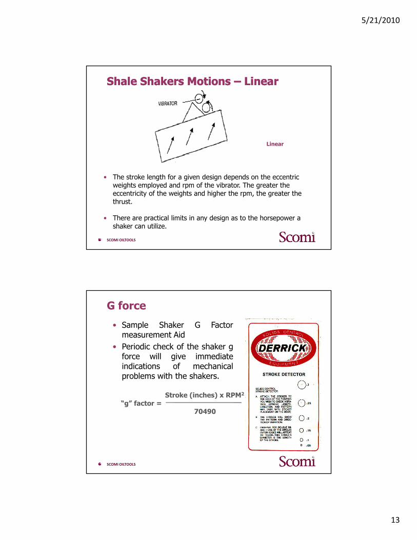
• The stroke length for a given design depends on the eccentric weights employed and rpm of the vibrator. The greater the eccentricity of the weights and higher the rpm, the greater the thrust.
• There are practical limits in any design as to the horsepower a shaker can utilize.
Linear
SCOMI OILTOOLS
G force
• Sample Shaker G Factormeasurement Aid
• Periodic check of the shaker gforce will give immediateindications of mechanicalproblems with the shakers.
Stroke (inches) x RPM2
“g” factor = 70490
5/21/2010
14
SCOMI OILTOOLS
Shale Shakers Shale Shakers –– Screening ComparisonScreening Comparison
The higher the ‘‘g’’ factor• The greater the solids separation possible. • The higher the solids capacity - the less tendency
there is for the screens to blind.
Blinding : Reduction of open area in a screening surface caused by
• Plugging OR Coating.
Screens are plugged - when solids are wedged or jammed in the screen opening
Coating is - reduction in the size opening of screen due to a buildup of a film in the wires such as salt, gypsum, polymer, etc.
SCOMI OILTOOLS
Shale Shakers Shale Shakers –– Screening ComparisonScreening Comparison
• A “g” factor that is too high for a shaker’s screensupports may reduce the life of a screen.
• Proper screen tension is critical to assure goodscreen life.
Shale shakers have capacity limits. Exceeding acapacity limit means excessive mud will bedischarged over the ends along with the solids.Capacity limits can only be defined when the screensare not blinded.

5/21/2010
15
SCOMI OILTOOLS
Shale Shakers Shale Shakers –– Screening ComparisonScreening Comparison
• There are two capacity limits on a shale shaker:
1. The solids capacity limit is the maximumamount of solids that a device will convey.
2. The liquid limit is the maximum gpm capacityfor various drilling muds.
• Usually the solids capacity limit is encounteredonly when drilling soft, gummy formations ordrilling large diameter holes with high penetrationrates.
• The overall capacity of the shaker is acombination of the solids capacity limit and theliquid capacity limit.
SCOMI OILTOOLS
Gumbo ProblemGumbo Problem
• Gumbo solids are young, unconsolidated clays that tend to be sticky and easily dispersed.
• They hydrate and disperse on the way up the hole.
• What is not removed at surface is entrained in the mud system as colloidal sized particles (>2 microns).
• Problems include:
• The more energy put into gumbo solid, the more “plastic” the solid becomes.
• Blinding of shaker screens.
• Increased mud dilution and chemical additions.
5/21/2010
16
SCOMI OILTOOLS
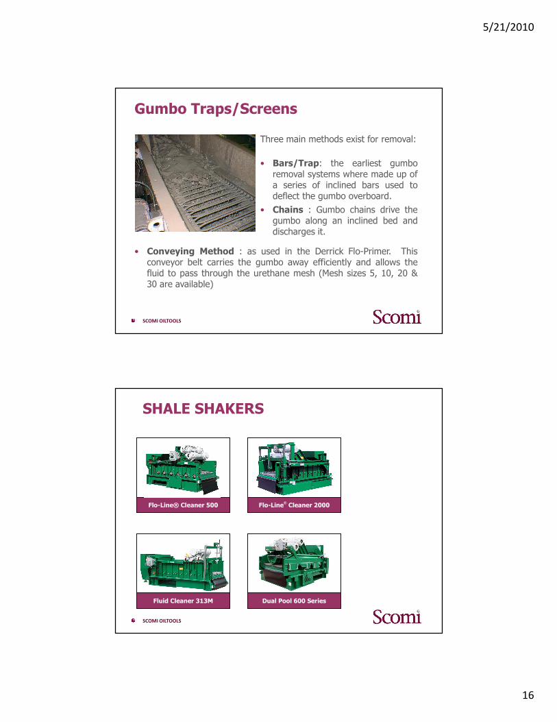
Gumbo Traps/Screens
Three main methods exist for removal:
• Bars/Trap: the earliest gumboremoval systems where made up ofa series of inclined bars used todeflect the gumbo overboard.
• Chains : Gumbo chains drive thegumbo along an inclined bed anddischarges it.
• Conveying Method : as used in the Derrick Flo-Primer. Thisconveyor belt carries the gumbo away efficiently and allows thefluid to pass through the urethane mesh (Mesh sizes 5, 10, 20 &30 are available)
SCOMI OILTOOLS
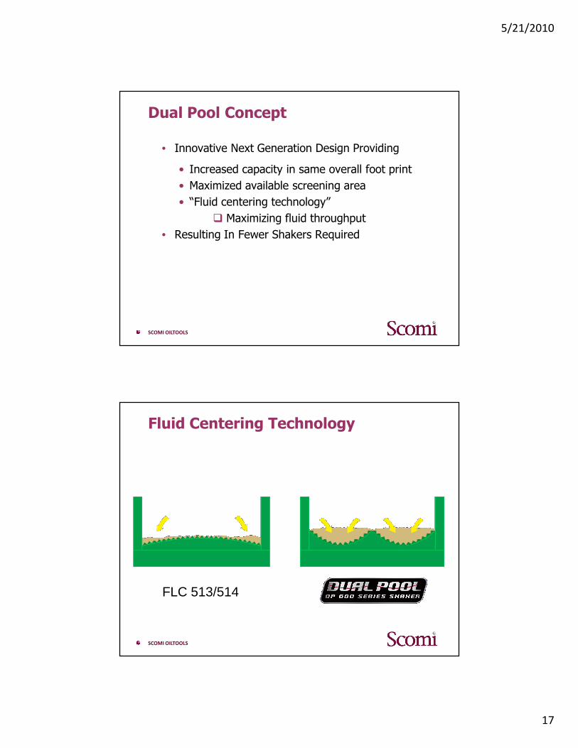
SHALE SHAKERS
Dual Pool 600 SeriesDual Pool 600 Series
Flo-Line® Cleaner 2000Flo-Line® Cleaner 2000Flo-Line® Cleaner 500Flo-Line® Cleaner 500
Fluid Cleaner 313MFluid Cleaner 313M
5/21/2010
17
SCOMI OILTOOLS
Dual Pool Concept
• Innovative Next Generation Design Providing
• Increased capacity in same overall foot print
• Maximized available screening area
• “Fluid centering technology”
� Maximizing fluid throughput
• Resulting In Fewer Shakers Required
SCOMI OILTOOLS
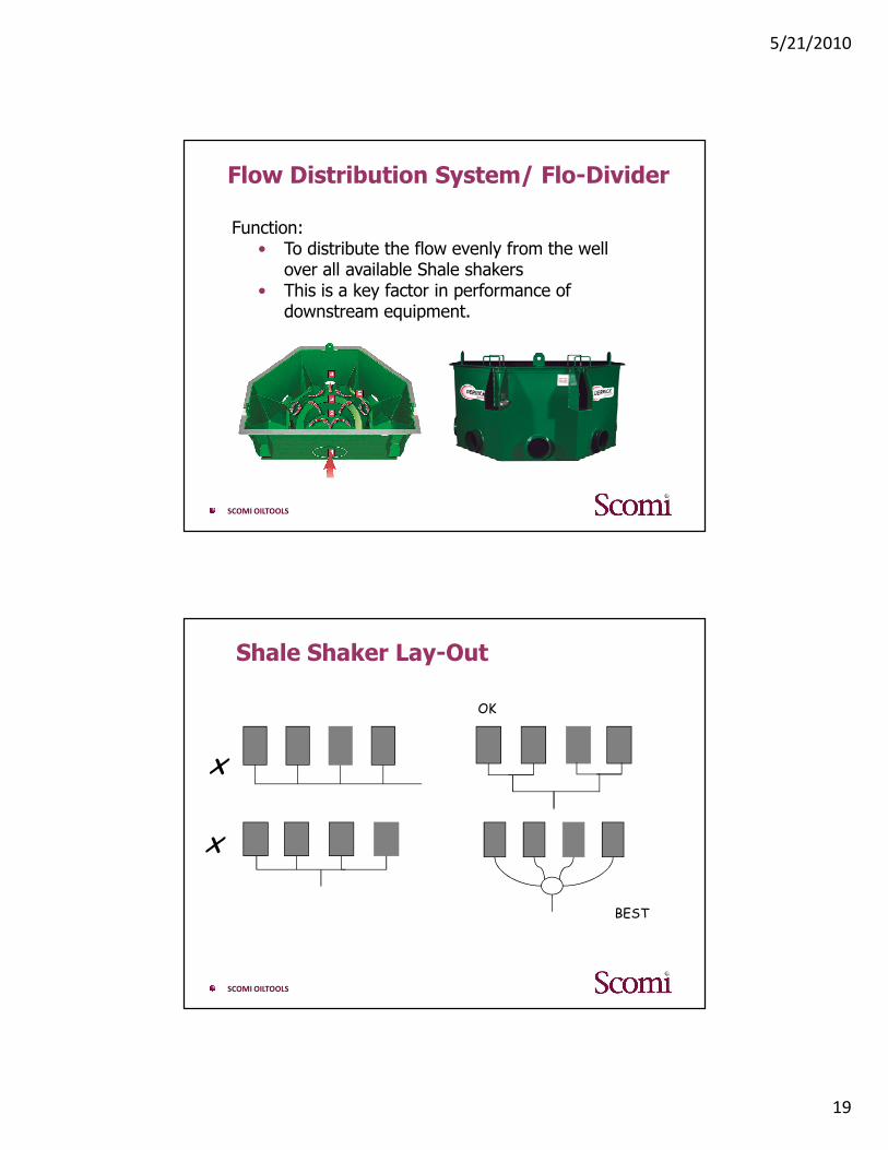
Fluid Centering Technology
FLC 513/514

5/21/2010
18
SCOMI OILTOOLS
Dual Pool 618
SCOMI OILTOOLS
Optional Scalping Deck
5/21/2010
19
SCOMI OILTOOLS
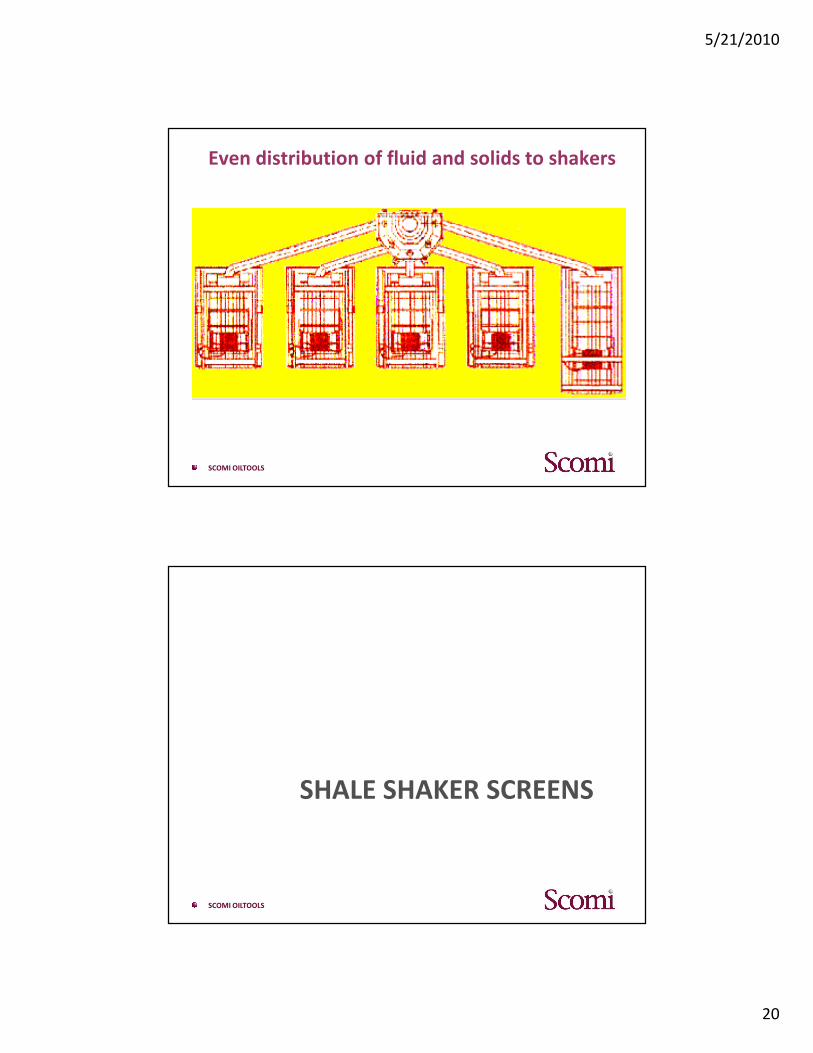
Flow Distribution System/ Flo-Divider
Function:• To distribute the flow evenly from the well
over all available Shale shakers• This is a key factor in performance of
downstream equipment.
SCOMI OILTOOLS
Shale Shaker Lay-Out
x
x
BEST
OK
5/21/2010
20
SCOMI OILTOOLS
Even distribution of fluid and solids to shakers
SCOMI OILTOOLS
SHALE SHAKER SCREENS

5/21/2010
21
SCOMI OILTOOLS
SHALE SHAKER SCREENS
• Screens are a filtering device.
• High-speed linear motion shakers have allowed screen technology to move forward.
• Screens finer than 200 mesh are now common.
SCOMI OILTOOLS
SHALE SHAKER SCREENS
• Histrorically, the drilling industry has rankedshale shaker screens by
� mesh count� opening size� percent open area.
• The field operating procedure has been to run asfine a mesh as possible on un-weighted fluidsand fine as fine as possible up to 200 mesh (74microns) on weighted.

5/21/2010
22
SCOMI OILTOOLS
SHALE SHAKER SCREENS
Shale Shaker Screens● Shale shakers remove solids by processing
solid-laden drilling fluid over the vibratingscreens.
● Particles smaller than the screen openingspass through the screen along with the liquid.
● Larger particles are separated into the shakeroverflow and disposed of.
Desirable characteristics for shaker screens are:● Large liquid flow rate capacity● Plugging and blinding resistance● Acceptable service life● Easy identification.
SCOMI OILTOOLS
SHALE SHAKER SCREENS
Factors that determine the effectiveness of a screen are
●mesh size
● screen design.
Mesh Size.
●The screen opening size determines the particle size a shaker can remove.
●Screen mesh is the number of openings per linear inch as measured from the centre of the wire.
●A mesh count of 50 x 50 indicates a square mesh having 50 openings per inch in both axis directions.
●A 60 x 40 mesh indicates a rectangular opening having 60 openings per inch in one direction and

5/21/2010
23
SCOMI OILTOOLS
SHALE SHAKER SCREENS
● Liquid forms a high surface tension film on thewires reducing the effective opening.
● This film effect is increased with increasingviscosity.
● Piggy backing – small particles are attached tobigger particles.
● Smaller particles than the openings can beremoved but liquid through put is reduced.
SCOMI OILTOOLS
SHALE SHAKER SCREENS
Screens are available in two and three dimensionaldesigns.
● Two-dimensional screens can be classified as:● Panel Screens, are manufactured with two or
three layers bound at each side by the hook strips.● Perforated Plate Screens, are manufactured with
two or three layers bonded to a perforated metalplate. These can be patched / repaired

5/21/2010
24
SCOMI OILTOOLS
SHALE SHAKER SCREENS
● Three-dimensional screens :● Three-dimensional screens are manufactured with
a perforated base plate and covered with acorrugated screen cloth. This configurationprovides more screen area than the two-dimensional screen configuration.
SCOMI OILTOOLS
SCREENS DESIGN
Solids Form Continuous BedImpeding Fluid Throughput
Gravity Forces SolidsInto Troughs
Difference between two dimensions and three
5/21/2010
25
SCOMI OILTOOLS
Screen Conductance
• Screen conductance is the permeability of the screen clothdivided by the thickness of the cloth and is given in kilo-Darcy's per millimeter (KD/MM).
• Screen conductance is a measure of the amount of fluid thatwill pass through a screen.
• Screen permeability is determined by the porosity of thescreen and wire surface area, which causes drag on the fluidand restricts movement of the fluid through the screen.
• Conductance can be calculated from knowledge of the weaveof the cloth, the mesh count, and the wile diameter.
SCOMI OILTOOLS
SHALE SHAKER SCREENS LABELING
Two API Regulationfor screen comparison / evaluation
API RP 13E• Solid Removal Potency-Cut Point• Open Area for liquid to flow• Conductance
API RP 13C• API No• Equivalent mesh size• Conductance• Open Area
5/21/2010
26
SCOMI OILTOOLS
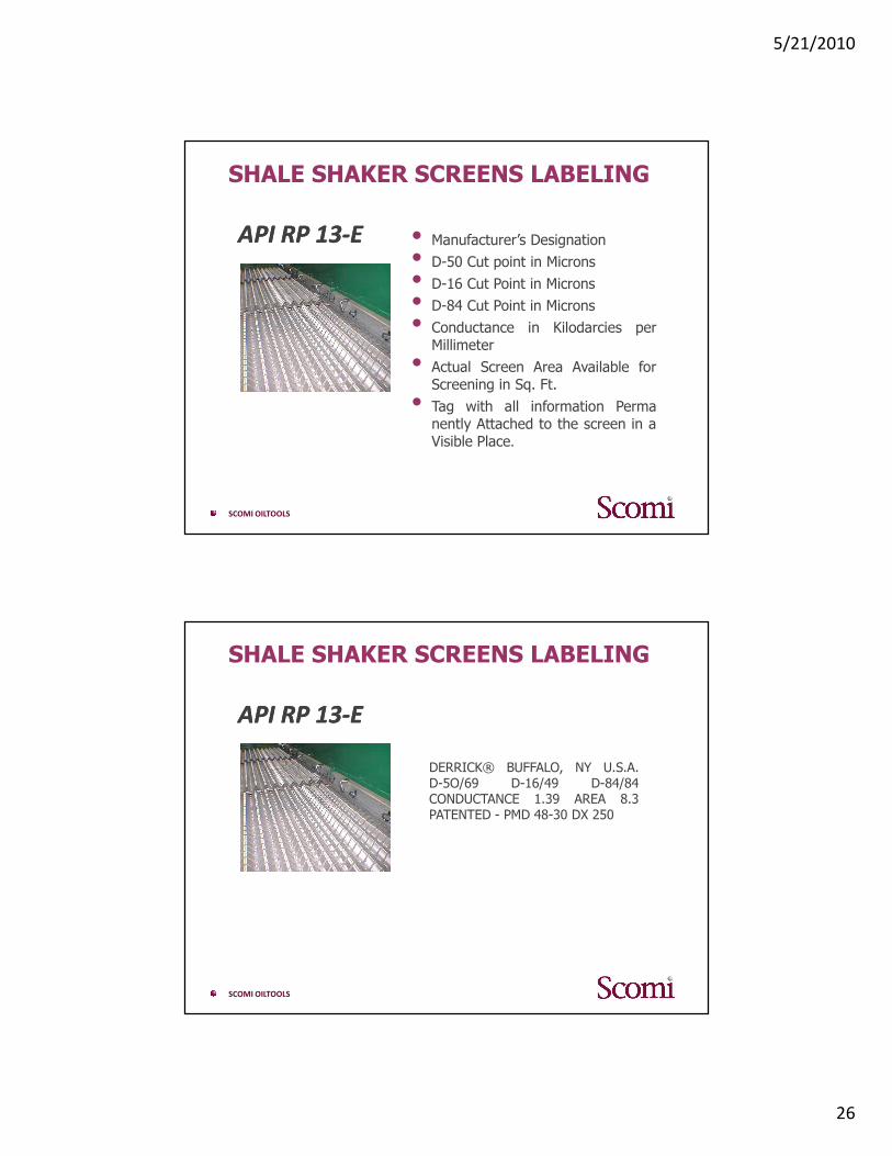
SHALE SHAKER SCREENS LABELING
API RP 13-EAPI RP 13-E • Manufacturer’s Designation
• D-50 Cut point in Microns
• D-16 Cut Point in Microns
• D-84 Cut Point in Microns
• Conductance in Kilodarcies perMillimeter
• Actual Screen Area Available forScreening in Sq. Ft.
• Tag with all information Permanently Attached to the screen in aVisible Place.
SCOMI OILTOOLS
SHALE SHAKER SCREENS LABELING
API RP 13-EAPI RP 13-E
DERRICK® BUFFALO, NY U.S.A.D-5O/69 D-16/49 D-84/84CONDUCTANCE 1.39 AREA 8.3PATENTED - PMD 48-30 DX 250

5/21/2010
27
SCOMI OILTOOLS
API RP 13C Labeling
API RP 13C specifies that a permanent tag or label shall be attached to screen in a position that is both visible and legible
SCOMI OILTOOLS
SHAKER SCREENS ARRANGEMENT
For double-deck shakers
• Run a coarser screen on top and a finer screen onbottom.
• The coarser screen should be at least two meshescoarser.
• Watch for a torn bottom screen.
• Replace or patch torn screens at once.
• Cover 75% to 80% of the bottom screen with mudto maximize utilization of the available screen area.
• It is very important that the bottom screen bechecked often for tears.
For example, use a combination of 100 mesh and 80 mesh NOT 100 mesh and 50 mesh
5/21/2010
28
SCOMI OILTOOLS
SHAKER SCREENS ARRANGEMENT
For a single—deck shaker with parallel screens• Try to run all the same mesh screens.• If coarser screens are necessary to prevent mud
loss, no more than two meshes should be on theshaker at one time
• Finer mesh screen closest to the weir side andcoarse towards beach area.
• Cover 75% to 80% of the screen area with mud toproperly utilize the screen surface.
• If a shaker has multiple screens in series or parallelshakers are used, separation is determined by the -coarsest screen.
Shakers in parallel should use the samemesh screens.
SCOMI OILTOOLS
HYDRO-CYCLONES
5/21/2010
29
SCOMI OILTOOLS
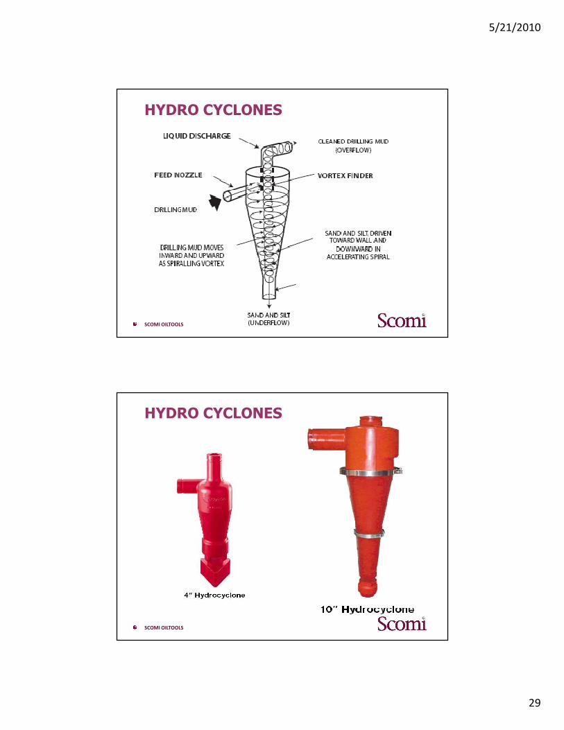
HYDRO CYCLONES
SCOMI OILTOOLS
HYDRO CYCLONES
5/21/2010
30
SCOMI OILTOOLS
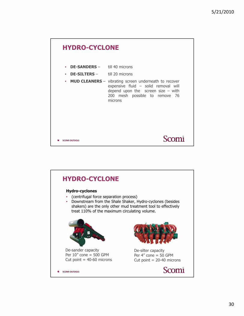
HYDRO-CYCLONE
• DE-SANDERS – till 40 microns
• DE-SILTERS – till 20 microns
• MUD CLEANERS – vibrating screen underneath to recoverexpensive fluid – solid removal willdepend upon the screen size – with200 mesh possible to remove 76microns
SCOMI OILTOOLS
HYDRO-CYCLONE
Hydro-cyclones
• (centrifugal force separation process)• Downstream from the Shale Shaker, Hydro-cyclones (besides
shakers) are the only other mud treatment tool to effectivelytreat 110% of the maximum circulating volume.
De-silter capacityPer 4” cone = 50 GPMCut point = 20-40 microns
De-sander capacityPer 10” cone = 500 GPMCut point = 40-60 microns

5/21/2010
31
SCOMI OILTOOLS
Hydro-Cyclone – Operating Principles
• Feed Chamber is cylindrical
• Mud inlet at the top of feed chamberis tangent to the wall
• Involute flow – from circular feed inlet-
turbulent flow for longer period – reduced separation efficiency
• Tangential flow – from rectangular feed
inlet -reduces turbulence – increase separation efficiency
• Solid Discharge end is conical calledunderflow
• Vortex Finder - Extending inwardsat the top & in the center
• Overflow opening – much larger thaninlet & underflow
SCOMI OILTOOLS
Hydro-Cyclone – Operating Principles
• Centrifugal pump provides high velocity –resulting in Centrifugal forces
• Vortex Finder causes the stream to spiraldownwards
• Solids are thrown outwards toward thehydrocyclone wall, in the downwardspiraling stream
• The solids separation based on density &size
• same density cuttings size matters
• Increasing forces with narrowing of thecone results in inner layer of liquidturning back upwards
• In balanced design cyclone – last of theliquid turns back upward, but solids dueto high inertia & high downward velocity,continue out the underflow.
5/21/2010
32
SCOMI OILTOOLS
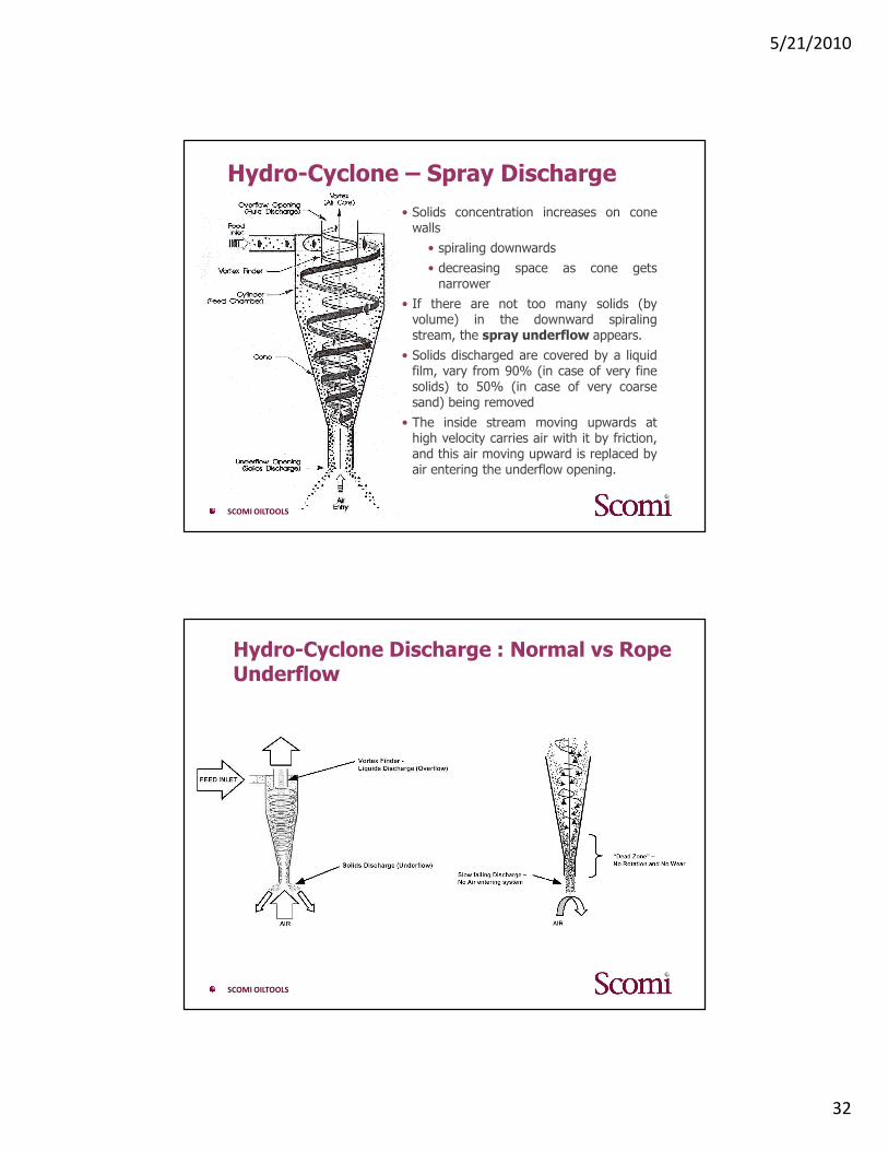
Hydro-Cyclone – Spray Discharge
• Solids concentration increases on conewalls
• spiraling downwards
• decreasing space as cone getsnarrower
• If there are not too many solids (byvolume) in the downward spiralingstream, the spray underflow appears.
• Solids discharged are covered by a liquidfilm, vary from 90% (in case of very finesolids) to 50% (in case of very coarsesand) being removed
• The inside stream moving upwards athigh velocity carries air with it by friction,and this air moving upward is replaced byair entering the underflow opening.
SCOMI OILTOOLS
Hydro-Cyclone Discharge : Normal vs Rope Underflow

5/21/2010
33
SCOMI OILTOOLS
Hydro-Cyclone Discharge : Normal vs Rope Underflow
SCOMI OILTOOLS
Hydro-Cyclone Discharge: Spray Pattern
5/21/2010
34
SCOMI OILTOOLS
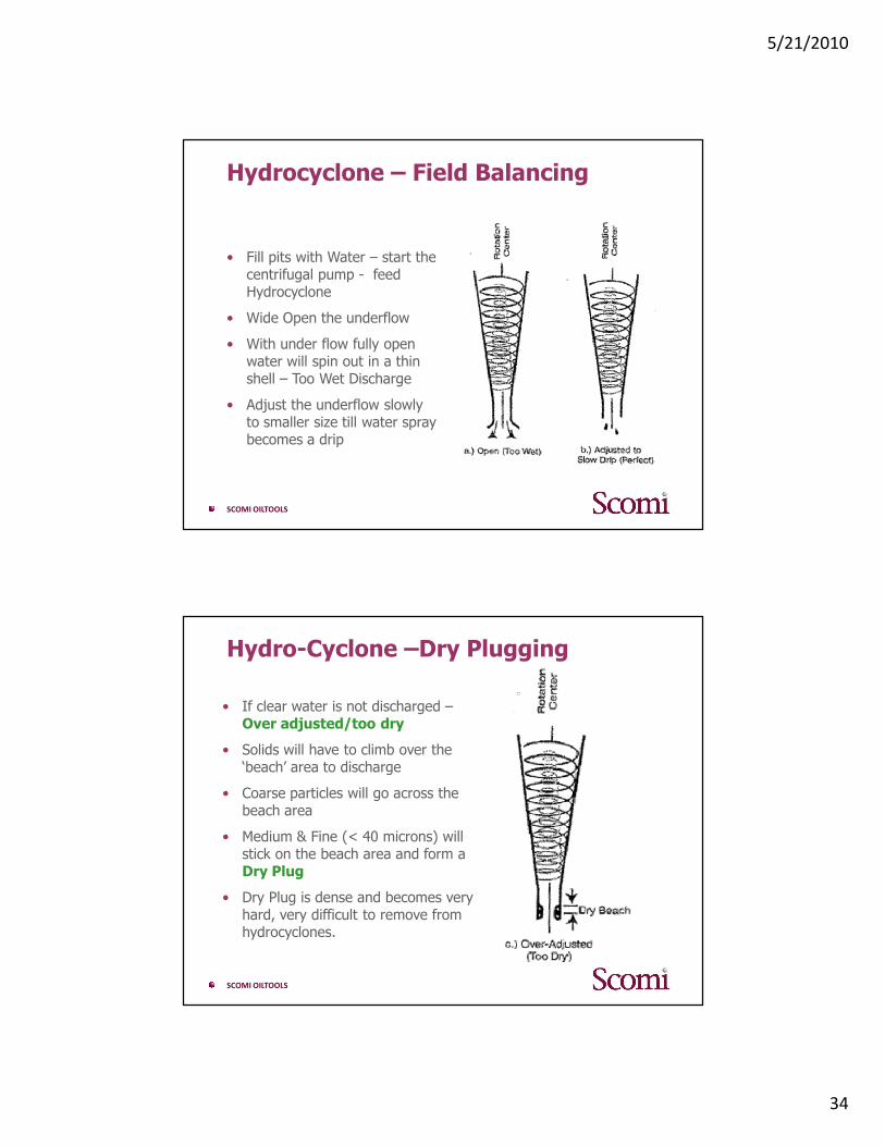
Hydrocyclone – Field Balancing
• Fill pits with Water – start the centrifugal pump - feed Hydrocyclone
• Wide Open the underflow
• With under flow fully open water will spin out in a thin shell – Too Wet Discharge
• Adjust the underflow slowly to smaller size till water spray becomes a drip
SCOMI OILTOOLS
Hydro-Cyclone –Dry Plugging
• If clear water is not discharged –Over adjusted/too dry
• Solids will have to climb over the ‘beach’ area to discharge
• Coarse particles will go across the beach area
• Medium & Fine (< 40 microns) will stick on the beach area and form a Dry Plug
• Dry Plug is dense and becomes very hard, very difficult to remove from hydrocyclones.

5/21/2010
35
SCOMI OILTOOLS
Hydro-Cyclone –Feed Plugging
● If Plugging is partial
• Reason hard objects like piece of welding rod/cement
• decrease in velocity at the inlet – loss of hydrocyclone action
• it works like a swirling funnel with all the mud going out the bottom in an inverted cone shape. Even clean mud from overflow may flow backward.
● If Plugging is complete
• Reason soft object like glove/rag/float collar rubber
• clean mud from the overflow of other cones is lost
• the mud loss rate is high
• discharge is straight
SCOMI OILTOOLS
Hydro-Cyclone – Feed Pressure
The pressure required for a hydro-cyclone to work properly is 75 feet head
mud wt. (ppg) X 4 = PSI at the feed inlet
It will be mud weight (ppg) X 4.4 at the centrifuge
5/21/2010
36
SCOMI OILTOOLS
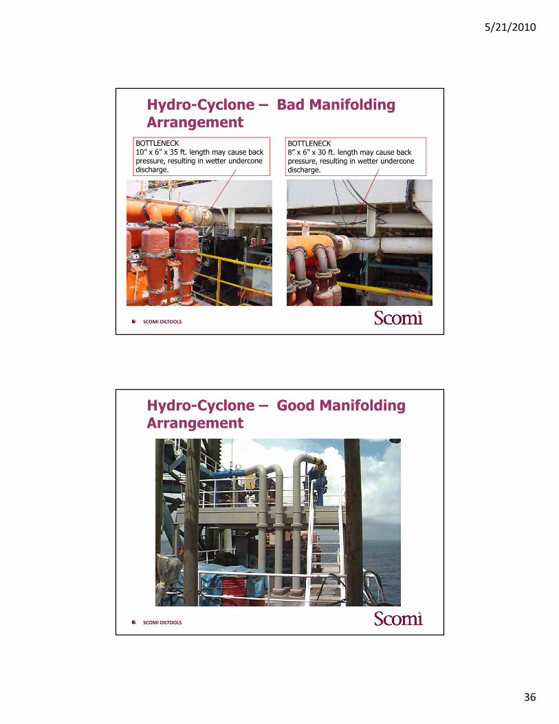
Hydro-Cyclone – Bad ManifoldingArrangement
BOTTLENECK 10” x 6” x 35 ft. length may cause back pressure, resulting in wetter underconedischarge.
BOTTLENECK 8” x 6” x 30 ft. length may cause back pressure, resulting in wetter underconedischarge.
SCOMI OILTOOLS
Hydro-Cyclone – Good ManifoldingArrangement
5/21/2010
37
SCOMI OILTOOLS
Hydro-Cyclone – Benefits
Benefits of having hydro-cyclones:
• Allows for coarser mesh or lower deck angle to be run on fine screen shakers while balancing the load between the two. Providing longer screen life (mud cleaner mode)
• Provides redundancy between shakers and centrifuges in closed or semi-closed loop systems
• Operate as a solids scalper for centrifuge operation
SCOMI OILTOOLS
Mud Cleaner
Mud Cleaner:Use to salvage expensive fluids back to active system

5/21/2010
38
SCOMI OILTOOLS
Desander
SCOMI OILTOOLS
Desilter
5/21/2010
39
SCOMI OILTOOLS
CENTRIFUGES
SCOMI OILTOOLS
Centrifuges – Principle & Theory of Operation
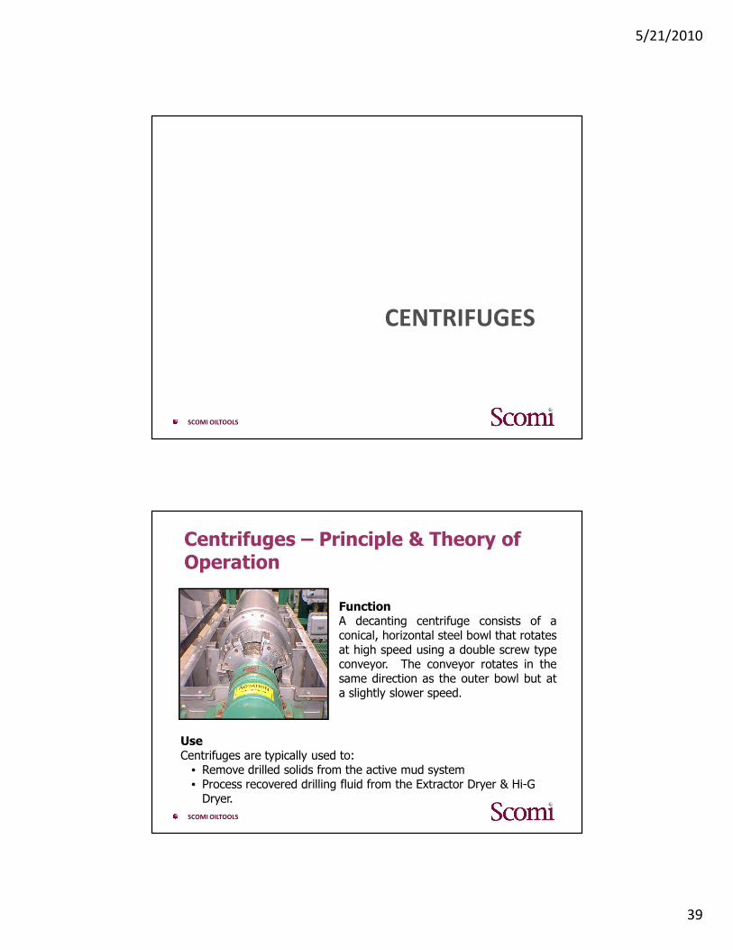
FunctionA decanting centrifuge consists of aconical, horizontal steel bowl that rotatesat high speed using a double screw typeconveyor. The conveyor rotates in thesame direction as the outer bowl but ata slightly slower speed.
UseCentrifuges are typically used to:
• Remove drilled solids from the active mud system• Process recovered drilling fluid from the Extractor Dryer & Hi-G
Dryer.
5/21/2010
40
SCOMI OILTOOLS
Decanting Centrifuge
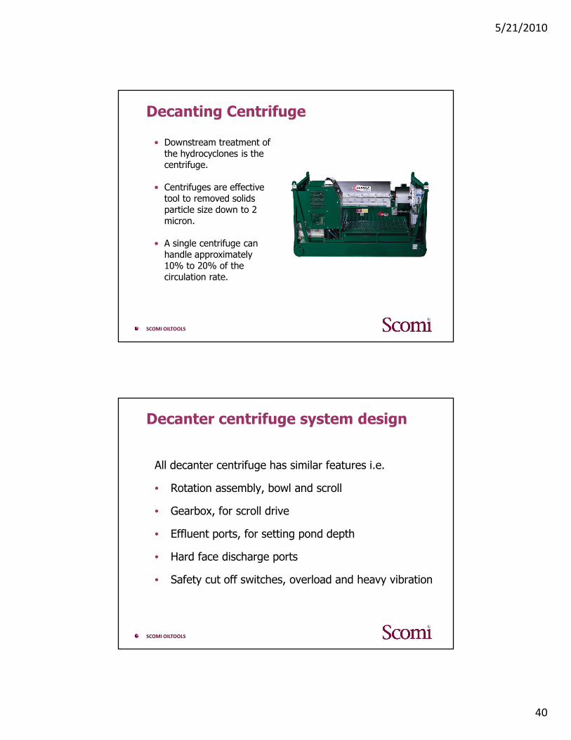
• Downstream treatment of the hydrocyclones is the centrifuge.
• Centrifuges are effective tool to removed solids particle size down to 2 micron.
• A single centrifuge can handle approximately 10% to 20% of the circulation rate.
SCOMI OILTOOLS
Decanter centrifuge system design
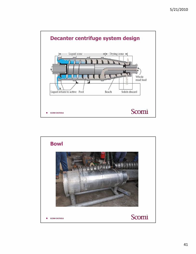
All decanter centrifuge has similar features i.e.
• Rotation assembly, bowl and scroll
• Gearbox, for scroll drive
• Effluent ports, for setting pond depth
• Hard face discharge ports
• Safety cut off switches, overload and heavy vibration
5/21/2010
41
SCOMI OILTOOLS
Decanter centrifuge system design
SCOMI OILTOOLS
Bowl
5/21/2010
42
SCOMI OILTOOLS
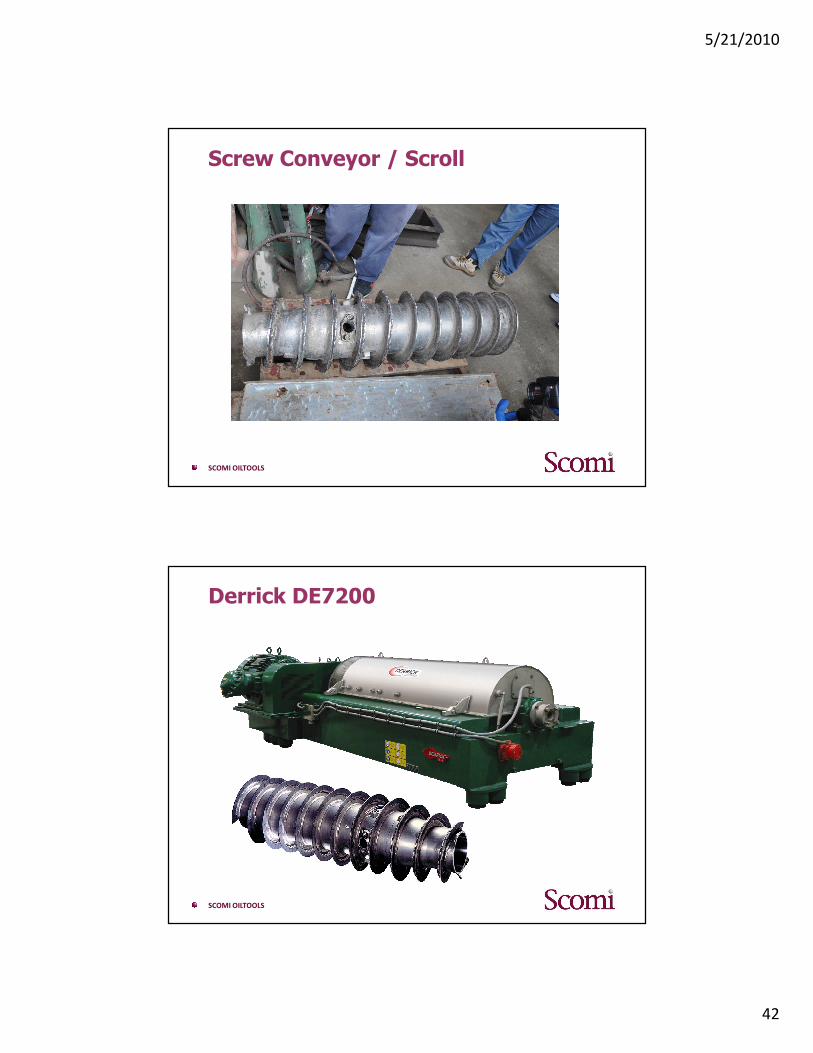
Screw Conveyor / Scroll
SCOMI OILTOOLS
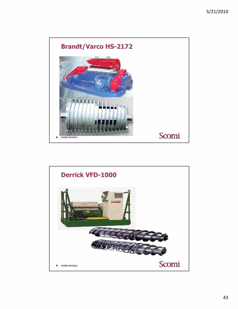
Derrick DE7200
5/21/2010
43
SCOMI OILTOOLS
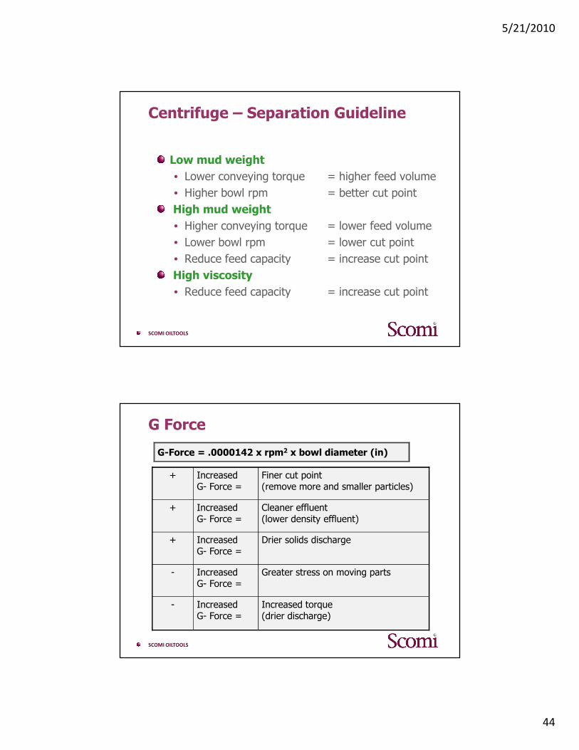
Brandt/Varco HS-2172
SCOMI OILTOOLS
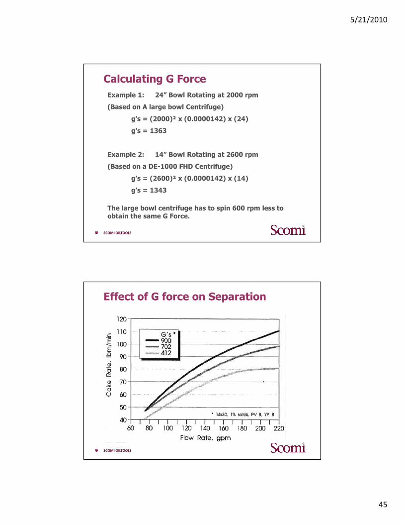
Derrick VFD-1000
5/21/2010
44
SCOMI OILTOOLS
Centrifuge – Separation Guideline
Low mud weight
• Lower conveying torque = higher feed volume
• Higher bowl rpm = better cut point
High mud weight
• Higher conveying torque = lower feed volume
• Lower bowl rpm = lower cut point
• Reduce feed capacity = increase cut point
High viscosity
• Reduce feed capacity = increase cut point
SCOMI OILTOOLS
G Force
G-Force = .0000142 x rpm2 x bowl diameter (in)
Cleaner effluent (lower density effluent)
IncreasedG- Force =
+
Increased torque (drier discharge)
IncreasedG- Force =
-
Greater stress on moving partsIncreasedG- Force =
-
Drier solids dischargeIncreasedG- Force =
+
Finer cut point (remove more and smaller particles)
IncreasedG- Force =
+
5/21/2010
45
SCOMI OILTOOLS
Calculating G Force
Example 1: 24” Bowl Rotating at 2000 rpm
(Based on A large bowl Centrifuge)
g’s = (2000)² x (0.0000142) x (24)
g’s = 1363
Example 2: 14” Bowl Rotating at 2600 rpm
(Based on a DE-1000 FHD Centrifuge)
g’s = (2600)² x (0.0000142) x (14)
g’s = 1343
The large bowl centrifuge has to spin 600 rpm less to obtain the same G Force.
SCOMI OILTOOLS
Effect of G force on Separation
5/21/2010
46
SCOMI OILTOOLS
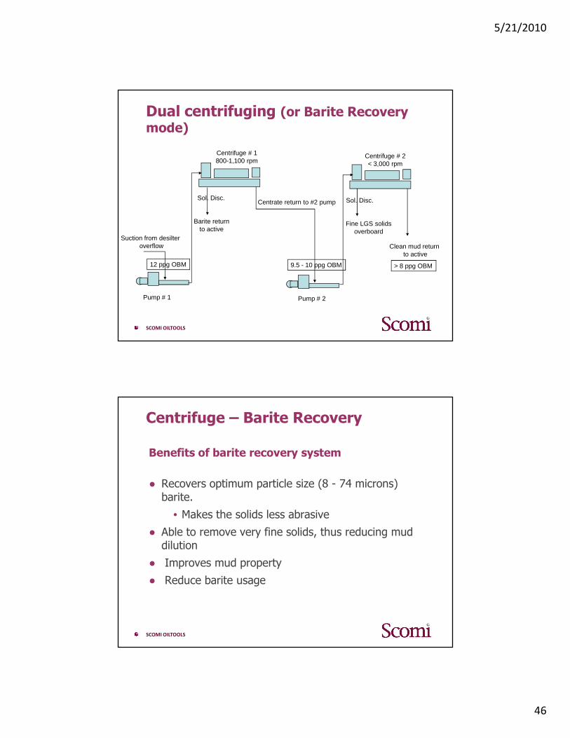
Dual centrifuging (or Barite Recovery mode)
Suction from desilteroverflow
Centrate return to #2 pump
Pump # 1 Pump # 2
Centrifuge # 1800-1,100 rpm
Centrifuge # 2< 3,000 rpm
Barite returnto active
Sol. Disc. Sol. Disc.
Fine LGS solidsoverboard
Clean mud return to active
12 ppg OBM 9.5 - 10 ppg OBM > 8 ppg OBM
SCOMI OILTOOLS
Centrifuge – Barite Recovery
Benefits of barite recovery system
● Recovers optimum particle size (8 - 74 microns) barite.
• Makes the solids less abrasive
● Able to remove very fine solids, thus reducing mud dilution
● Improves mud property
● Reduce barite usage
5/21/2010
47
SCOMI OILTOOLS
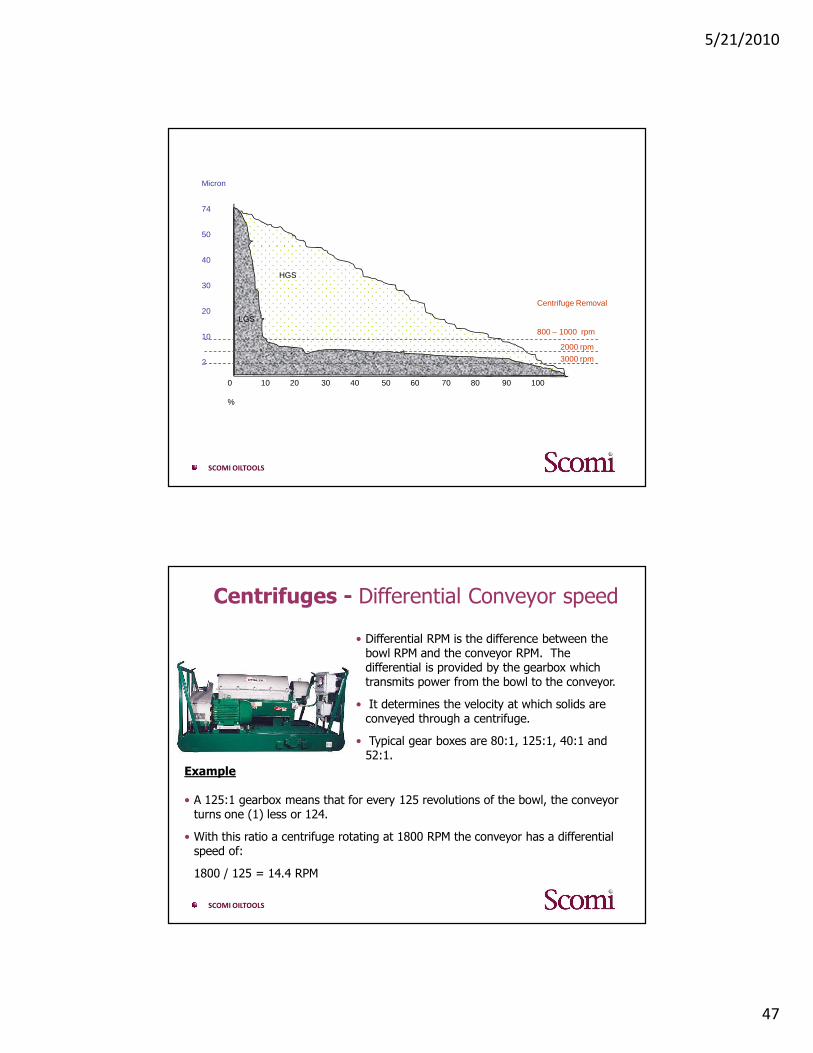
0 10 20 30 40 50 60 70 80 90 100
%
Micron
74
50
40
30
20
10
2
LGS
HGS
Centrifuge Removal
800 – 1000 rpm
2000 rpm
3000 rpm
SCOMI OILTOOLS
Centrifuges - Differential Conveyor speed
• Differential RPM is the difference between the bowl RPM and the conveyor RPM. The differential is provided by the gearbox which transmits power from the bowl to the conveyor.
• It determines the velocity at which solids are conveyed through a centrifuge.
• Typical gear boxes are 80:1, 125:1, 40:1 and 52:1.
Example
• A 125:1 gearbox means that for every 125 revolutions of the bowl, the conveyor turns one (1) less or 124.
• With this ratio a centrifuge rotating at 1800 RPM the conveyor has a differential speed of:
1800 / 125 = 14.4 RPM
5/21/2010
48
SCOMI OILTOOLS
Centrifuges - Operating Guidelines, Centrifuging Un-weighted Mud
• For the best separation the bowl should be run at maximum RPM.
• Operate the centrifuge just below the flood-out point.
• When processing the active system, the centrifuge feed should be taken from the desilter discharge compartment. The centrate should be returned to the next compartment downstream.
• The best feed rate and pond depth will depend on the size distribution of the drilled solids.
• Use a deeper pond and lower feed rates are more efficient when removing fine drilled solids.
• Field experimentation is necessary to optimize centrifuge set-up.
SCOMI OILTOOLS
DRILLING WASTE
MANAGEMENT

5/21/2010
49
SCOMI OILTOOLS
Cutting Dryer
SCOMI OILTOOLS
The Extractor Cuttings Dryer
● As increasingly strict limitations are placed on thedischarge of drilling fluids and their associateddrilled cuttings to the environment; the industryhas adapted specialized technology to comply withthese increasingly stringent dischargerequirements.
● To meet the challenge of low oil on cuttings(OOC), SCOMI Oiltools has developed theExtractor horizontal dryer which can reduce Oil OnCuttings (OOC) to below 4%
● Normal operating RPM 800

5/21/2010
50
SCOMI OILTOOLS
Typical Extractor Installation
SCOMI OILTOOLS
Typical Extractor Installation
5/21/2010
51
SCOMI OILTOOLS
Cutting Dryer
Cuttings DryerThe industry has recently adapted specialized system technology to comply with the strict limitations (EPA compliant) being placed on the discharge of synthetic base fluids and their associated drilled cuttings.
SCOMI OILTOOLS
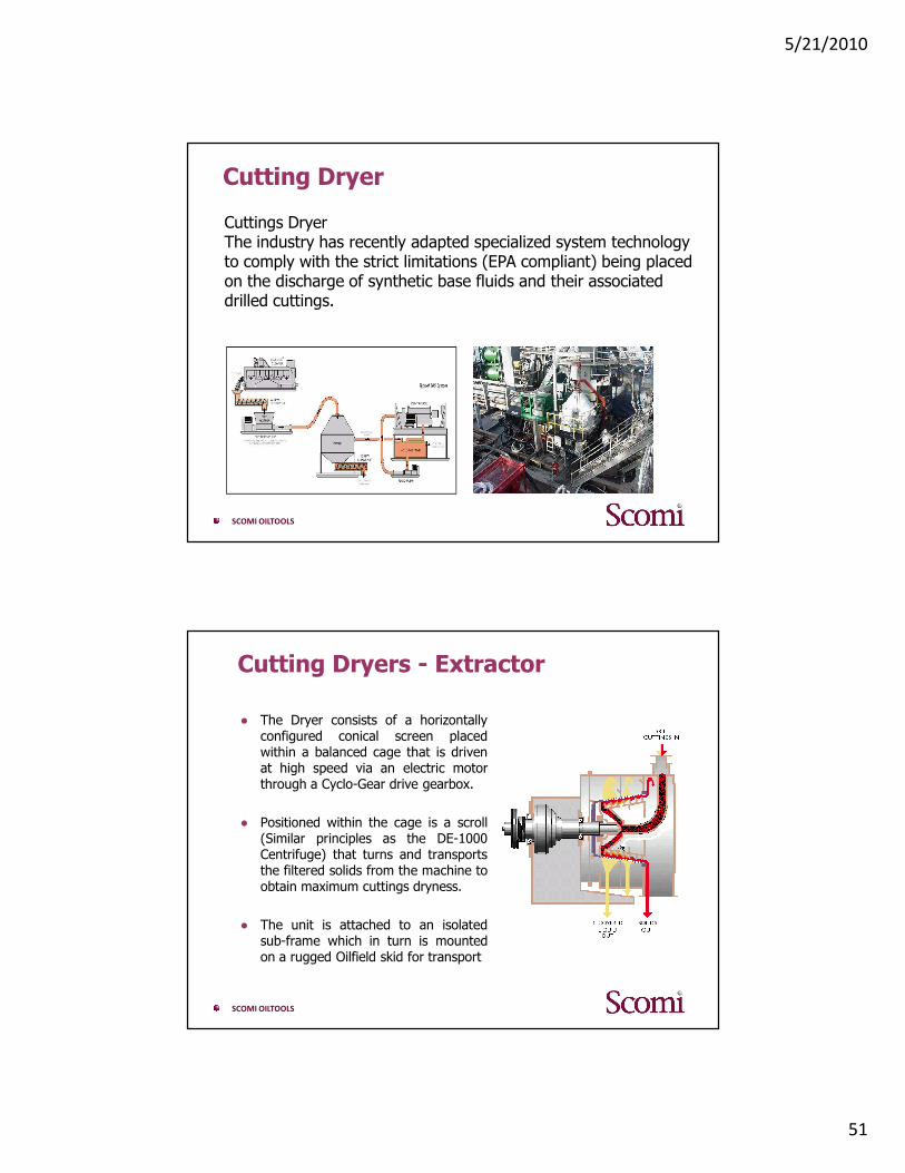
Cutting Dryers - Extractor
● The Dryer consists of a horizontallyconfigured conical screen placedwithin a balanced cage that is drivenat high speed via an electric motorthrough a Cyclo-Gear drive gearbox.
● Positioned within the cage is a scroll(Similar principles as the DE-1000Centrifuge) that turns and transportsthe filtered solids from the machine toobtain maximum cuttings dryness.
● The unit is attached to an isolatedsub-frame which in turn is mountedon a rugged Oilfield skid for transport

5/21/2010
52
SCOMI OILTOOLS
Cutting Dryers - Extractor
SCOMI OILTOOLS
Wet drill cuttings enter into the top of the dryer
Dry drill cuttings exit out the bottom of the dryer
Recycled drilling fluid is recovered out the side ports
Cutting Dryer - Flow Diagram
5/21/2010
53
SCOMI OILTOOLS
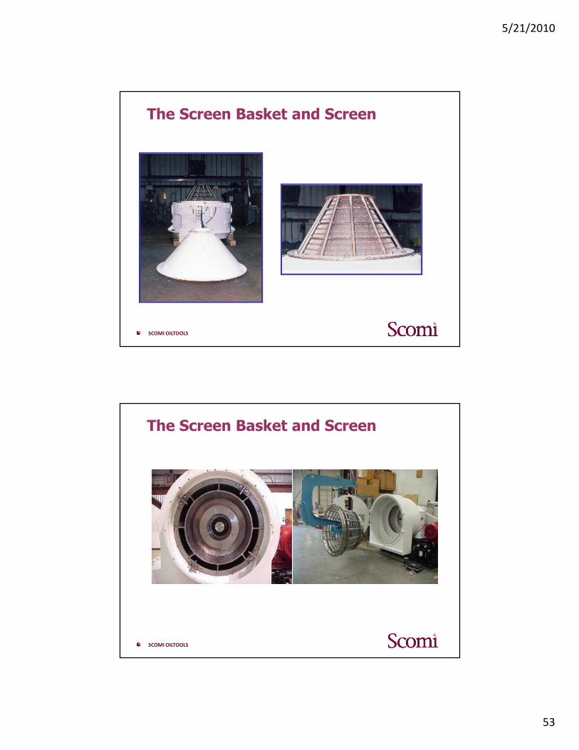
The Screen Basket and Screen
SCOMI OILTOOLS
The Screen Basket and Screen
5/21/2010
54
SCOMI OILTOOLS
Feed System
The dryer receives wet cuttings from the rig solids control equipment via an application specific combination of:
● Screw conveyor(s)
● Positive displacement cuttings pump
● Vacuum collection system.
● Gravity
SCOMI OILTOOLS
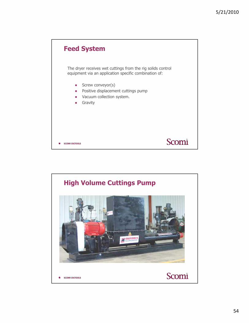
High Volume Cuttings Pump
5/21/2010
55
SCOMI OILTOOLS
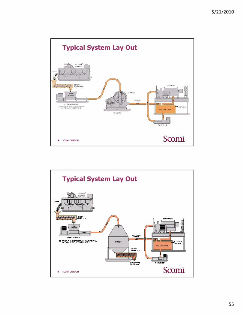
Typical System Lay Out
SCOMI OILTOOLS
Typical System Lay Out
5/21/2010
56
SCOMI OILTOOLS
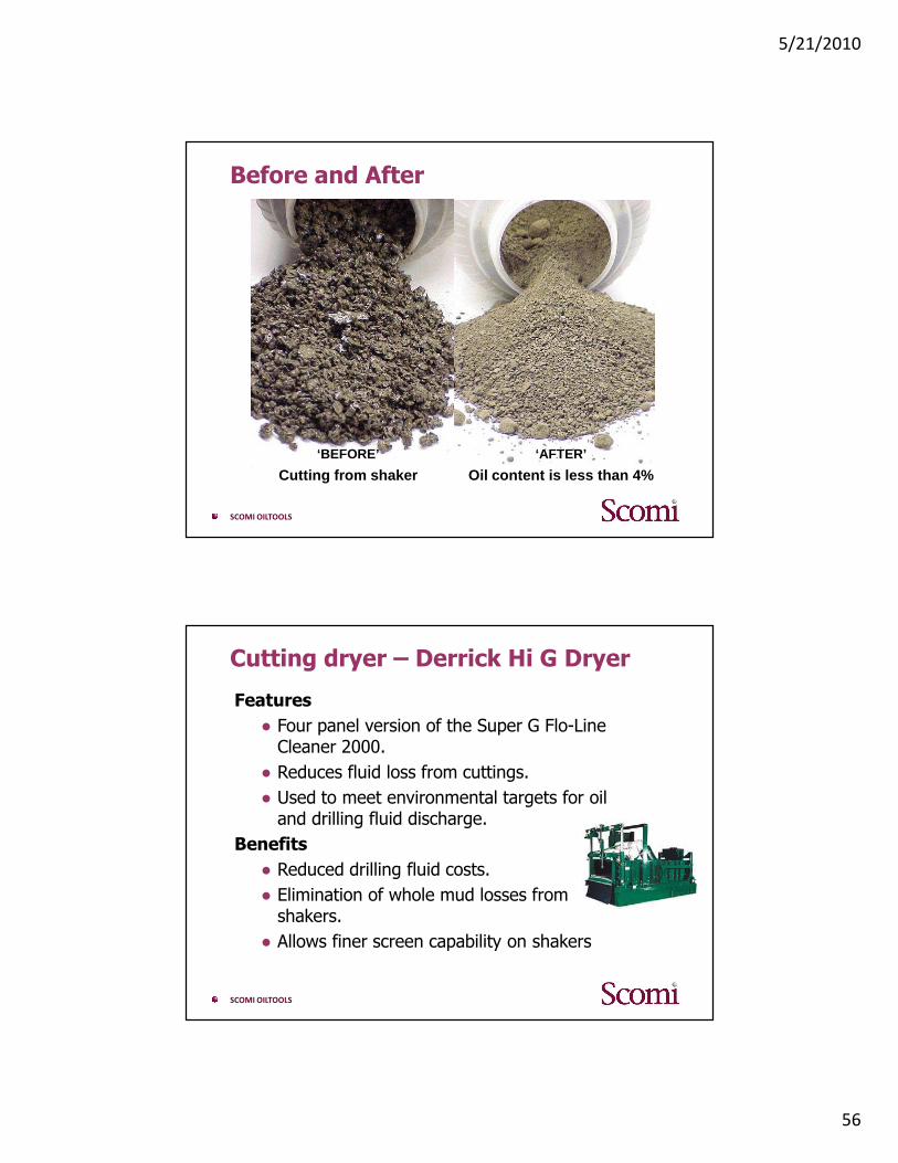
DRILLING WASTE MANAGEMENTBefore and After
‘BEFORE’
Cutting from shaker‘AFTER’
Oil content is less than 4%
SCOMI OILTOOLS
Cutting dryer – Derrick Hi G Dryer
Features
● Four panel version of the Super G Flo-Line Cleaner 2000.
● Reduces fluid loss from cuttings.
● Used to meet environmental targets for oil and drilling fluid discharge.
Benefits
● Reduced drilling fluid costs.
● Elimination of whole mud losses from shakers.
● Allows finer screen capability on shakers

5/21/2010
57
SCOMI OILTOOLS
SYSTEM LAYOUT
SCOMI OILTOOLS
Solids Control Equipments on the Rig
SHALE SHAKER
OVERFLOW
DESANDERDESILTERCENTRIFUGE
FROM
WELLBORE
UNDERFLOW UNDERFLOW UNDERFLOWUNDERFLOW
MIXING HOPER
MUD TREATMENT
(ADD CHEMICALS)
MUD PUMP
IN TO
WELLBORE
TANK # 2
SETTLING TANK
TANK # 3
DESANDER
TANK
TANK # 4
DESILTER TANK
TANK # 5
CENTRIFUGE
TANK
TANK # 6
SUCTION TANK
TANK # 1
SAND TRAP
TANK
5/21/2010
58
SCOMI OILTOOLS
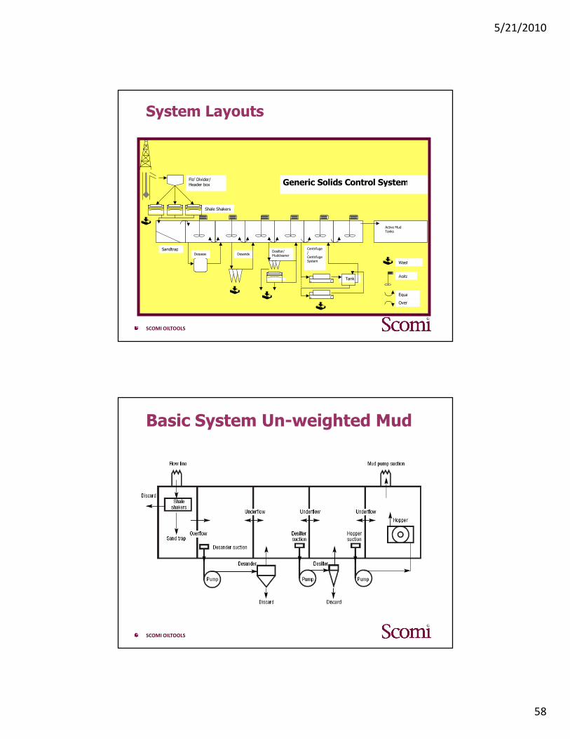
System Layouts
Tank
Desilter/MudcleanerDesande
r
SandtrapDegasse
r
Centrifuge/
CentrifugeSystem
Active MudTanks
Shale Shakers
Flo’ Divider/Header box Generic Solids Control System
�
�
�
�
� Waste
Agitator
Equaliser
Overflow
SCOMI OILTOOLS
Basic System Un-weighted Mud
5/21/2010
59
SCOMI OILTOOLS
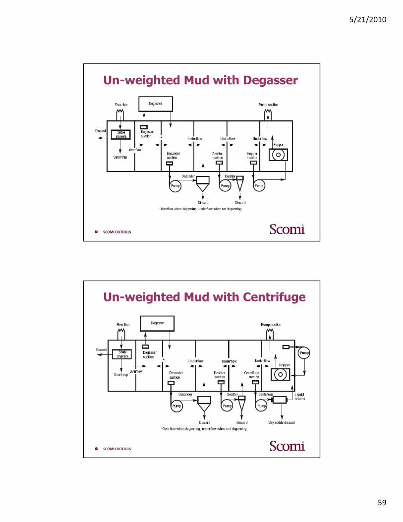
Un-weighted Mud with Degasser
SCOMI OILTOOLS
Un-weighted Mud with Centrifuge
5/21/2010
60
SCOMI OILTOOLS
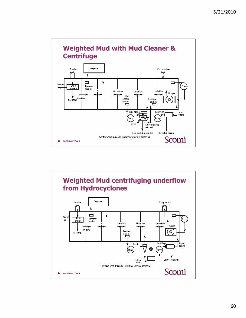
Weighted Mud with Mud Cleaner & Centrifuge
SCOMI OILTOOLS
Weighted Mud centrifuging underflow from Hydrocyclones