Embed Size (px)
Citation preview
9. Seal Systems 1 / 116Heat & Fluid Techniques in Power
9. Seal Systems
Vacuum
Pressure
High
Pressure

9. Seal Systems 2 / 116Heat & Fluid Techniques in Power
Introduction to Seal Systems 163
Brush Seal 635
Other Seals 766
Throttling Process 21
Steam Path Audit 92
Labyrinth Seal 444
Hydrogen Seal for Generator 877
9. Seal Systems 3 / 116Heat & Fluid Techniques in Power
Throttling Process [1/6]
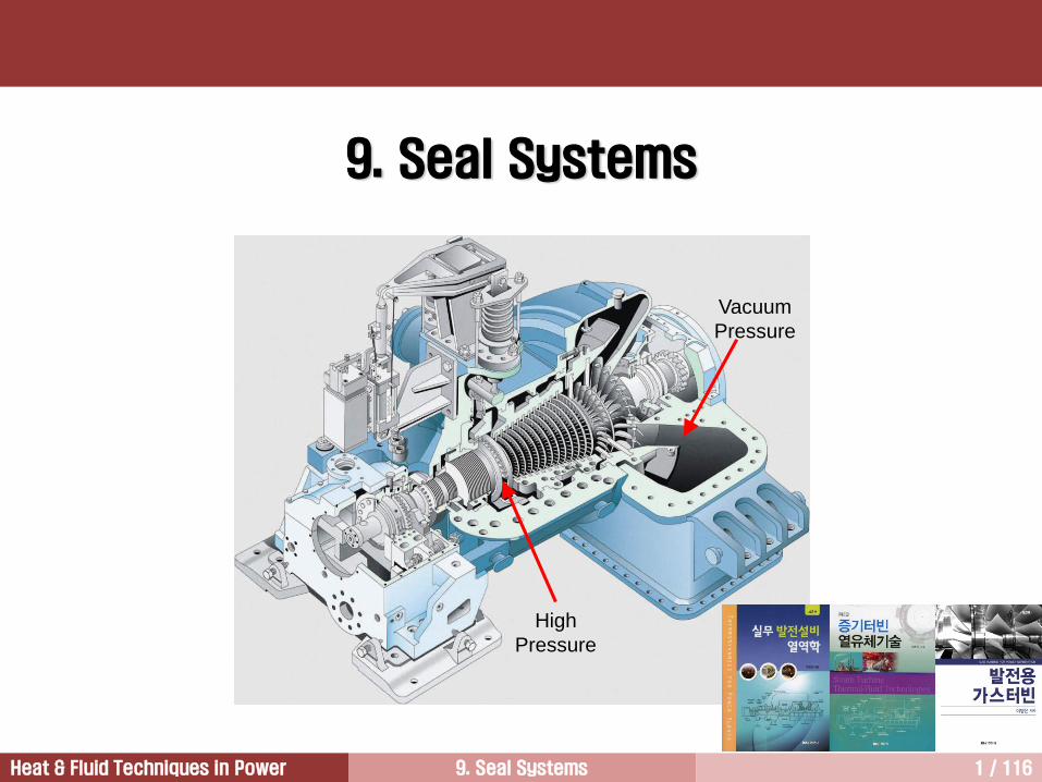
유체가 노즐이나 오리피스와 같이 갑자기 유로가 좁아지는 곳을 통과하면 외부와 열량이나 일의 교환 없
이도 압력이 감소하는 교축과정(throttling process) 발생.
교축과정이 발생하면 와류가 생성되어 에너지가 손실되면서 압력손실 발생.
작동유체가 액체인 경우 교축과정이 일어나서 압력이 액체의 포화압력보다 낮아지면 액체의 일부가 증발
하며, 증발에 필요한 열을 액체 자신으로부터 흡수하기 때문에 액체의 온도는 감소.
Pre
ssu
re P
1 2

9. Seal Systems 4 / 116Heat & Fluid Techniques in Power
열역학 제1법칙:
벽면에서의 열전달이 없으며, 이루어진 일이나 공급된 일도 없으며, 위치에너지 변화량도 무시할
수 있으므로,
속도가 40m/s 이하인 경우 운동에너지는 엔탈피 크기에 비해 매우 작다.
교축과정은 발전설비에서 자주 일어나는 과정인데, 특히 증기가 밸브를 통과할 때 압력강하가 발
생하며, 이를 교축과정이라 한다.
12 hh (교축과정 = 등엔탈피 과정)
1212
2
1
2
212122
1wzzgcchhq
02
1 2
1
2
212 cchh
Throttling Process [2/6]

9. Seal Systems 5 / 116Heat & Fluid Techniques in Power
작동유체가 이상기체인 경우 교축과정이 발생한 후에 엔탈피는 일정하게 유지됨.
엔탈피는 온도만의 함수이므로 교축과정 발생 후에 온도변화 없음.
그러나 작동유체가 증기인 경우에는 교축과정이 발생하면 압력과 온도가 떨어져서 에너지 수준이 낮아
짐. 주울-톰슨 효과(Joule-Thomson effect).
증기터빈 버켓커버 상부에는 증기누설을 방지하기 위해서 seal을 설치하여 증기누설 방지.
Seal을 통해서 누설되는 증기는 seal strips을 통과하면서 교축과정이 발생하기 때문에 실을 빠져나온
증기는 온도와 압력이 떨어져서 엔탈피가 낮아짐.
따라서 누설증기가 다음 단에서 주유동과 합류하더라도 주유동의 에너지 수준을 높이지 못하기 때문에
손실 발생 누설손실
즉 누설증기가 실을 빠져나오면서 에너지를 잃지 않았다면 다음 단에서 사용할 수 있지만 이미 잃어버
렸기 때문에 손실이 됨.
증기 특성
Throttling Process [3/6]

9. Seal Systems 6 / 116Heat & Fluid Techniques in Power
[Exercise 1] Compare the velocity at 2
그림에서 A와 B는동일한규격의도관이다. 도관 B에오리피스를설치하였다. 그리고도관 B 입구압력은도관 A와동일하게유지시킨상태에서질량유량을절반으로줄였다. 그리고이때도관 B의하류 2에서압력을측정하였더니입구압력의절반이었다. 이때오리피스하류 2에서유속을비교하시오.
1 2
A
1 2
B
Exercise
Throttling Process [4/6]

9. Seal Systems 7 / 116Heat & Fluid Techniques in Power
[Solution]
문제에서주어진조건은다음과같다.
(1)
그리고
교축과정이일어나면온도는변하지않는다. 따라서이상기체라고가정하면다음관계식이성립한다.
그러므로다음관계식이성립한다.
and , therefore, (2)
유동단면적이일정하기때문에식 (1)은다음과같이된다.
(3)
식 (2)와식 (3)을결합하면다음과같은식을얻는다.
따라서질량유량이달라지더라도압력을조절하여하류에서일정한속도를얻을수있다.
2,2,2,2,
2
1
2
1ABAB VAVAmm
1,1,2,2
1
2
1ABB ppp
2,2,1,1, BBBB pp
2,1,2 BB
2,2,2,2,2
1AABB VV
2,1,1, AAB 2,2,2 BA
2,2, AB VV
Exercise
Throttling Process [5/6]

9. Seal Systems 8 / 116Heat & Fluid Techniques in Power
The steam has an initial pressure P1 at the entry to the seal
assembly.
After expanding past the first constriction, the pressure will
have been reduced to condition Xo, with pressure P2.
In the chamber formed between the first and second seal
strips, the kinetic energy of the steam is destroyed and
reconverted at constant pressure P2 to condition X.
From point X, there is then a further expansion of the steam
past the second constriction, with the pressure falling to P3 at
condition Yo.
The kinetic energy is again reconverted in the chamber
between the second and third seal strips, raising the thermal
energy level from Yo to Y at constant pressure P3.
This process of expansion and kinetic energy reconversion is
continued throughout the series of seal strips until the final
expansion takes the steam to condition Qo at pressure P5.
The locus of the points Xo….Qo is called the Fanno curve.
h
s
T1
P1 P2P3 P4
P5
Xo YoZo
Qo
X Y Z
Leakage
Flow
P1 P2 P3 P4 P5
X Y Z
Rotation Side
Principle of Labyrinth Seal
Throttling Process [6/6]
9. Seal Systems 9 / 116Heat & Fluid Techniques in Power
Introduction to Seal Systems 3
Brush Seal 5
Other Seals 6
Throttling Process1
Steam Path Audit2
Labyrinth Seal 4
Hydrogen Seal for Generator 7

9. Seal Systems 10 / 116Heat & Fluid Techniques in Power
Definition and Purpose
Steam path audit is to assess the condition of the steam path to identify performance
degradation of the unit and to point out the causes and locations of power and efficiency
losses.
The results of the audit identify specific problem areas and quantify the impact of the
problems in order to assist the owner in making decisions whether to repair or replace
steam path components.
Steam Path Audit
Benefits of Steam Path Audit
Provides detailed inspection of steam path.
Quantify heat rate, power and efficiency impact on component-by-component basis.
Aid economic decisions during the repair outage.
Prioritize maintenance decisions on a benefit-to cost ratio.
Quantify the quality of turbine repairs by performing a closing steam path audit.
Provides excellent record/history of equipment conditions for future reference.

9. Seal Systems 11 / 116Heat & Fluid Techniques in Power
Areas Addressed in Steam Path Audit
• nozzles
• buckets
• shaft end packings where rotors emerge
from casing
• poorly fitting joints
• other miscellaneous leakages
1) Leakage
• deposits
• corrosion
• solid particle erosion
• mechanical damage
2) Surface Roughness
• deposits
• foreign objects
• mechanical damage
3) Flow Blockage
• solid particle erosion
• water droplet erosion
• mechanical damage
4) Flow Path Modification
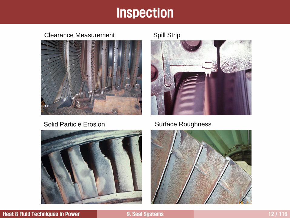
9. Seal Systems 12 / 116Heat & Fluid Techniques in Power
Spill Strip
Surface RoughnessSolid Particle Erosion
Clearance Measurement
Inspection

9. Seal Systems 13 / 116Heat & Fluid Techniques in Power
Sample –200 MW, 3000 rpm, 14710 kPa/535C/535C, 2 Flow LP
Power Loss Distribution
Opening Audit Closing Audit

9. Seal Systems 14 / 116Heat & Fluid Techniques in Power
Opening Audit Closing Audit
Sample –200 MW, 3000 rpm, 14710 kPa/535C/535C, 2 Flow LP
Power Loss Distribution – HP Turbine

9. Seal Systems 15 / 116Heat & Fluid Techniques in Power
Opening Audit Closing Audit
Sample –200 MW, 3000 rpm, 14710 kPa/535C/535C, 2 Flow LP
Heat Rate Loss Distribution

9. Seal Systems 16 / 116Heat & Fluid Techniques in Power
Introduction to Seal Systems 3
Brush Seal 5
Other Seals 6
Throttling Process1
Steam Path Audit2
Labyrinth Seal 4
Hydrogen Seal for Generator 7

9. Seal Systems 17 / 116Heat & Fluid Techniques in Power
TO ATMOSPHEREGLAND EXHAUSTERS
A Typical Steam Seal System

9. Seal Systems 18 / 116Heat & Fluid Techniques in Power
Seal
설치 위치 및 목적
• 로터 양 끝 케이싱 관통 부위
- HP/IP터빈: 터빈 내부 증기 외부(대기중) 누설 방지
- LP터빈: 외부 공기 LP터빈 누입 방지
• 버켓 팁: 버켓 열 압력차에 의한 증기누설 최소화
• 다이아프램 축 관통 부위: 노즐 열 압력차에 의한 증기누설 최소화

9. Seal Systems 19 / 116Heat & Fluid Techniques in Power
Turbine Stage Sealing System
Flow Coefficient
0.58
0.45
0.46
0.38
0.30
Nozzle Profile
15%
Bucket
Profile
15%
Nozzle
Secondary
15%Bucket Secondary
15%
Tip
Leakage
22%
Shaft Packing
Leakage 7%
Root Leakage 4%Rotation 3%
Carryover 4%

9. Seal Systems 20 / 116Heat & Fluid Techniques in Power
Balance Piston
Welding Balance Piston
The reaction design has a significant pressure drop
across the buckets and high thrust. Therefore, a
balance piston, which is normally built into the rotor,
is installed in high-pressure zones of single-flow
turbines to offset the thrust. Otherwise, the turbine is
designed with double-flow. Some designers also use
a balance piston on impulse turbines that have a high
thrust. Balance Piston
(Siemens)

9. Seal Systems 21 / 116Heat & Fluid Techniques in Power
① Valve and admission
② Profile
③ Shaft & inter-stage seal
④ Extraction & exhaust
⑤ Reheat pressure
⑥ X-over pressure
⑦ Moisture
⑧ Mechanical
Com
po
nen
t L
osse
s R
ela
ted
to T
urb
ine O
utp
ut
HP Turbine IP Turbine LP Turbine
Steam Turbine Efficiency
1970
1990
87%
90%
%
2.0
1.0
Siemens
Losses of Turbine Components
600 MW Reheat Steam Turbine

9. Seal Systems 22 / 116Heat & Fluid Techniques in Power
The installation of steam seals is a cost-effective
means for improving steam turbine efficiency and
power output.
Steam leakage losses are a major component of
controllable losses in large steam turbines.
A demonstrated improvement in turbine section
efficiencies of 5% can be achieved for full section
seal upgrades.
The leakage loss can be increased up to 1% of
available energy of steam turbine.
The amount of steam leakage is strongly related to
the operating clearance between the rotating and
stationary elements that are separated by the seal.
A second major influence on steam leakage is the
pressure difference that separates the inlet and exit
of the seal assembly. Seals located in regions of high
pressure drop experience greater leakage flow.
Generals

9. Seal Systems 23 / 116Heat & Fluid Techniques in Power
Tip Leakage [1/7]
Tip leakage flow go through the tip clearance driven by the pressure difference between the up- and
downstream at tip. This flow is function of clearance area and sealing arrangement.
The leakage flow jet mixes out firstly in the clearance space and this mixing process is irreversible because
of throttling loss.
The output of the steam turbine reduces as the leakage flow increases. This is because the amount and
velocity of the main flow reduce as the leakage flow increases.
Front stages, where the blade height is low and pressure difference across the seal is high, are more
affected by leakage loss than rear ones.
In order to decrease tip losses, for any given stage, the radial distribution of the row pressure drop (degree of
reaction) has to be optimized. This means that the degree of reaction at the tip should be decreased, but the
degree of reaction at the hub should be increased to minimize the leakage losses.
The modification of the degree of reaction is done by means of twist and lean.
The seal design is dependent on the pressure drop across the blades. Reaction turbines that high pressure
drops across the blades require the labyrinth type seal, whereas impulse turbines with small pressure drops
across the blades require only spill strips.

9. Seal Systems 24 / 116Heat & Fluid Techniques in Power
This loss is considered in different ways
depending on whether the blade is covered or
uncovered.
The major parameters affecting leakage flow
are tip clearance, degree of reaction, blade
turning, and blade loading (local pressure
difference between the pressure and suction
side).
The tip flow goes through the tip clearance from
the pressure side to the suction side of the
blade.
Tip leakage flow rolls up into a vortex and
interacts with the secondary flow.
The secondary flow and tip leakage flow
interaction produces a distinct interface.
Flow in Free Tip Blades
Tip Leakage [2/7]

9. Seal Systems 25 / 116Heat & Fluid Techniques in Power
From Payne et. al. (2003)
CFD Result for Tip Leakage Flows – Free Tip Blade
Tip Leakage [3/7]

9. Seal Systems 26 / 116Heat & Fluid Techniques in Power
Tip Vortex – Free Tip Blade
Tip Leakage [4/7]

9. Seal Systems 27 / 116Heat & Fluid Techniques in Power
Leakage
clearance
Tip Leakage [5/7]

9. Seal Systems 28 / 116Heat & Fluid Techniques in Power
Tip Clearance, fraction of passage height
Tu
rbin
e E
ffic
ien
cy,
fra
ctio
n o
f e
ffic
iency w
ith
ou
t cle
ara
nce
.01 .02 .03 .040
100
99
98
97
96
95
94
93
92
91
90
010203040
50
60
70 De
gre
e o
f re
actio
n,
(%)
Tip-Clearance Correlation for Unshrouded Blades
Tip Leakage [6/7]
9. Seal Systems 29 / 116Heat & Fluid Techniques in Power
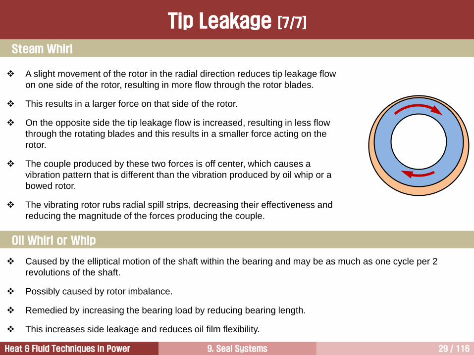
A slight movement of the rotor in the radial direction reduces tip leakage flow
on one side of the rotor, resulting in more flow through the rotor blades.
This results in a larger force on that side of the rotor.
On the opposite side the tip leakage flow is increased, resulting in less flow
through the rotating blades and this results in a smaller force acting on the
rotor.
The couple produced by these two forces is off center, which causes a
vibration pattern that is different than the vibration produced by oil whip or a
bowed rotor.
The vibrating rotor rubs radial spill strips, decreasing their effectiveness and
reducing the magnitude of the forces producing the couple.
Steam Whirl
Oil Whirl or Whip
Caused by the elliptical motion of the shaft within the bearing and may be as much as one cycle per 2
revolutions of the shaft.
Possibly caused by rotor imbalance.
Remedied by increasing the bearing load by reducing bearing length.
This increases side leakage and reduces oil film flexibility.
Tip Leakage [7/7]

9. Seal Systems 30 / 116Heat & Fluid Techniques in Power
Impulse Reaction
Bucket
Tip
Diaphragm
Root
cylindrical
drum type
rotor
disc wheels
shrunk on to
a rotor shaft
Comparison of Leakage

9. Seal Systems 31 / 116Heat & Fluid Techniques in Power
a b
HP IP
1
c d
LP
2
d
46
6
35
89
7
10
1- integrated HP-IP casing and its front (a), central (b), and rear (c) seals, 2-two double flow
LP casings and their end seals (d), 3&4-headers of the HP-IP and LP end seals, 5&6-gland
governors of steam pressure in these headers, 7-outside source of sealing steam, 8-gland
steam ejector, 9-gland steam condenser, 10-to a feedwater heater.
Shaft Packing Leakage [1/3]
Steam Flow for Gland Packing Seals
9. Seal Systems 32 / 116Heat & Fluid Techniques in Power
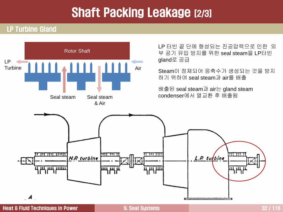
LP 터빈 끝 단에 형성되는 진공압력으로인한 외부 공기 유입 방지를 위한 seal steam을 LP터빈gland로공급
Steam이정체되어 응축수가 생성되는 것을 방지하기 위하여 seal steam과 air를 배출
배출된 seal steam과 air는 gland steam
condenser에서열교환 후 배출됨
Rotor Shaft
Air
Seal steam Seal steam
& Air
LP
Turbine
LP Turbine Gland
Shaft Packing Leakage [2/3]

9. Seal Systems 33 / 116Heat & Fluid Techniques in Power
Shaft Packing Leakage [3/3]

9. Seal Systems 34 / 116Heat & Fluid Techniques in Power
MHI
Root Leakage [1/3]
Retractable Packing

9. Seal Systems 35 / 116Heat & Fluid Techniques in Power
This figure shows the force diagram
around a labyrinth seal of a
retractable design during both
normal operation and at
startup/shutdown when the steam
pressures are significantly lower.
It can be seen that there is a
radially inward force, which is the
sum of the spring force and the
steam force.
In the HP and IP turbine, the steam
force is considerably larger than the
spring force.
Retractable Packing
Root Leakage [2/3]

9. Seal Systems 36 / 116Heat & Fluid Techniques in Power
Retractable packing was developed to avoid packing rubs that can occur during unit startup when the shaft
passes through critical speeds.
Retractable packing provides a very large shaft clearance during unit startup, when turbine steam flow and
local pressure are very low.
During normal operation when the flow and pressure are at design levels, the seal element close, or move
radially inward (closer to the shaft). In this case, leakage losses are reduced because of reduced clearance.
Unlike conventional spring-backed packing, the springs in retractable packing assemblies hold the packing
at a large radial clearance to the shaft (typically 0.15 in.).
As the turbine steam flow increases, the increasing steam pressure closes the packing, causing the springs
to compress to mechanical stops.
By operating in this manner, retractable packing eliminates startup problems caused by the shaft rubbing
and bowed rotors.
Over the life span of the equipment, this results in higher sustained efficiency and lower maintenance costs.
Retractable packing can be installed throughout the steam path with the exception of the three outer rings in
the shaft end packing boxes
Commercial suppliers of variable clearance packing include Brandon Engineering, TurboCare, and Dresser-
Rand.
Retractable Packing
Root Leakage [3/3]

9. Seal Systems 37 / 116Heat & Fluid Techniques in Power
Full-Annular
Rub Damage
Undamaged Seal Continuous Rub Damage on End-Glands
Damage and Degradation of Seals [1/4]

9. Seal Systems 38 / 116Heat & Fluid Techniques in Power
Seals are often damaged by shaft rubs that increase leakage flow and reduce efficiency. Therefore, seals
should be designed to withstand shaft vibration experienced during startups and shutdowns.
The stationary and rotating surfaces of turbine seal elements can be subjected to high-speed rubs, large
pressure differentials, and high temperatures of surrounding steam and metal.
If rubbing occurs with high-contact forces, the seal knives and shaft will heat up to excessive levels, raising
the temperature of the affected components beyond the austenitizing temperature.
The surrounding steam creates a quenching effect that can cause the seal material to become brittle and
susceptible to failure during next rubbing.
The knife deformation damage has two detrimental effects on sealing efficiency. First, it will increase leakage
area. Second, the rub will modify the shape of the knife profile, changing the sharp knife corner to a rounded
corner and increasing the flow coefficient.
Similarly, there is a potential for quenching damage to the shaft, resulting in areas of increased hardness and
possible crack initiation sites.
The resulting deformation of the shaft surface due to wear will also increase the seal clearance and leakage
flow.
Damage and Degradation of Seals [2/4]

9. Seal Systems 39 / 116Heat & Fluid Techniques in Power
Labyrinth seal knives have tapered cross-sections so that any accidental rub will limit frictional heating by
reducing the contact area.
A major part of the effort in reducing the steam leakage involves minimizing the incidence and severity of
these rubs during unit startup, shutdown, and system transients.
Shaft rubs can occur during startup when the rotor passes through critical speed and the resulting mid-span
lateral shaft deflections are high enough to exceed the clearance.
In many steam turbines backing springs are used to hold seal segments in place but also allow them to be
compliant in the radial direction in the event of a hard rub between the shaft and the seal.
Seal degradation and the need to periodically restore damaged elements to their original condition represent
a barrier to the current industry desire to extend scheduled maintenance intervals on large steam turbines.
Seal damages are also associated with water droplet erosion and solid particle erosion.
Damage and Degradation of Seals [3/4]

9. Seal Systems 40 / 116Heat & Fluid Techniques in Power
The most common source of seal damage is shaft rubs during unit startup and shutdown, which experience
high lateral vibration at the critical speeds.
Once a rub starts, local heating of the shaft due to friction can cause thermal distortion and worsen vibration
and the associated rub.
Plant operators need to be aware of the shaft critical speeds and avoid any extended operation during
startup/shutdown at these speeds.
Also, the degree of balance of the shaft system will affect the lateral vibration amplitude at critical speed, so
rotating unbalance should be maintained as low as possible in order to protect the seal elements.
Damage and Degradation of Seals [4/4]

9. Seal Systems 41 / 116Heat & Fluid Techniques in Power
Causes of Rubbing and Seal Damage
The unit will pass through critical speeds during startup.
The critical speed vibration amplitude is typically highest at the mid-span of the rotors, and it can damage the
shaft seals on the diaphragms if the vibration amplitude exceeds the clearances.
Conventional seals use stiff backing springs to hold the labyrinth seal rings radially inward.
These springs permit some level of protection by allowing the labyrinth assembly to move outward in the
event of hard rubbing.
Depending on the spring stiffness, the extent and consequences of startup rubbing remain serious.
Retractable seals allow the labyrinth seal assemblies to displace radially away from the rotor surface when
steam pressures are low. This kind of condition happens during unit startup and shutdown.
The rub-tolerant strip, which is designed slightly taller than the standard knives surrounding it, can be used
to minimize seal damage.
This strip is the first to come in contact with the shaft in rubbing conditions and thus protects the remaining
labyrinth knives.
1. Unit Startup [1/2]

9. Seal Systems 42 / 116Heat & Fluid Techniques in Power
This design is used in combination with a soft backing spring so that the protective strip pushes the seal
assembly away.
For those seals incorporating rub-tolerant strips, the clearances between the conventional knife-edged seal
strip and rotating surfaces are set at normal design levels.
The rub-tolerant strip has a marginally smaller clearances, but it is large enough so that during normal unit
startup, contact will not occur.
At startup, the pressures in the steam path are considerably lower, therefore, the steam force on the gland
rings are not large. In this case, relatively low contact pressures are developed at the rub surfaces, and the
contacting force is determined by the soft backing spring.
Distortion of turbine casings during thermal transients (e.g. in start-up or rapid load changes) can damage
radial seals between the rotor and stationary parts, especially if the fixed blades are mounted directly into the
casings.
1. Unit Startup [2/2]
Causes of Rubbing and Seal Damage

9. Seal Systems 43 / 116Heat & Fluid Techniques in Power
When a unit is shutdown either under a controlled condition or emergency condition, the main and
intermediate stop and/or control valves close, and the steam pressure levels within the flow path decay as
the rotor slows.
For a normal shutdown, the steam pressure is controlled, but the rotor must pass through its critical speeds
with the potential to initiate rubs if procedures are not followed.
So, under controlled shutdown conditions, the radial inward force on the labyrinth seal assemblies when the
rotor passes through critical speed is governed by the spring device.
If the steam pressure is not reduced as required during shutdown, the steam forces are added to the backing
spring forces, hold the labyrinth assembly in place with tight clearances, and thus risk damaging the seals
during coast down.
3. Unit Operating Transients and Trips
Unit trip represent a risk of seal damage during an uncontrolled shutdown.
Under these conditions, the rotor can be accelerated momentarily to overspeed and vibrate either in going to
overspeed or coasting down through its critical speeds.
Immediately upon disconnection from the grid, the stop and control valves will assume a control status, but
there is a finite period when steam pressures are high, and heavy shaft-seal rubs can occur at critical
speeds.
2. Unit Shutdown
Causes of Rubbing and Seal Damage

9. Seal Systems 44 / 116Heat & Fluid Techniques in Power
Introduction to Seal Systems 3
Brush Seal 5
Other Seals 6
Throttling Process1
Steam Path Audit2
Labyrinth Seal 4
Hydrogen Seal for Generator 7

9. Seal Systems 45 / 116Heat & Fluid Techniques in Power
Configuration
Labyrinth Seal

9. Seal Systems 46 / 116Heat & Fluid Techniques in Power
Stepped labyrinth seals (high-low packing)
with multiple knives are the most common
method used in order to reduce leakage
flow by providing a tortuous flow area.
The leakage jet in a stepped labyrinth seal
is bounded by counter-rotating vortices that
restrict the leakage flow.
Flow in a Stepped Labyrinth Seal
Labyrinth Seal

9. Seal Systems 47 / 116Heat & Fluid Techniques in Power
This type of seal is the most common one used in large steam turbines.
Backing springs push the seal radially inwards toward the turbine shaft. The compliance of these springs
permit some radial deflection during heavy rubbing.
Fluid pressure produces a radially inward force and makes a minimum clearance. This additional force is
normally proportional to turbine flow and is insignificant under no steam flow.
Rubbing between the shaft and the packing can cause nonuniform shaft heating that leads to a bowed rotor
condition and shaft vibration.
Turbine
Rotor
Conventional
Seal
(in a rub
condition)Steam Flow
Spring Tension
1. Spring-Backed Labyrinth Seal
Labyrinth Seal

9. Seal Systems 48 / 116Heat & Fluid Techniques in Power
Retractable Packing Arrangement Pressure Distribution
This is developed by Ronald E.
Brandon in the early 1980s and
is installed in many steam
turbines
2. Retractable Packing
Labyrinth Seal

9. Seal Systems 49 / 116Heat & Fluid Techniques in Power
MHI
2. Retractable Packing
Labyrinth Seal

9. Seal Systems 50 / 116Heat & Fluid Techniques in Power
This figure shows the force diagram
around a labyrinth seal of a
retractable design during both
normal operation and at
startup/shutdown when the steam
pressures are significantly lower.
It can be seen that there is a
radially inward force, which is the
sum of the spring force and the
steam force.
In the HP and IP turbine, the steam
force is considerably larger than the
spring force.
2. Retractable Packing
Labyrinth Seal

9. Seal Systems 51 / 116Heat & Fluid Techniques in Power
Retractable packing was developed to avoid packing rubs that can occur during unit startup when the shaft
passes through critical speeds.
Retractable packing provides a very large shaft clearance during unit startup, when turbine steam flow and
local pressure are very low.
During normal operation when the flow and pressure are at design levels, the seal element close, or move
radially inward (closer to the shaft). In this case, leakage losses are reduced because of reduced clearance.
Unlike conventional spring-backed packing, the springs in retractable packing assemblies hold the packing at
a large radial clearance to the shaft (typically 0.15 in.).
As the turbine steam flow increases, the increasing steam pressure closes the packing, causing the springs
to compress to mechanical stops.
By operating in this manner, retractable packing eliminates startup problems caused by the shaft rubbing and
bowed rotors.
Over the life span of the equipment, this results in higher sustained efficiency and lower maintenance costs.
Retractable packing can be installed throughout the steam path with the exception of the three outer rings in
the shaft end packing boxes
Commercial suppliers of variable clearance packing include Brandon Engineering, TurboCare, and Dresser-
Rand.
2. Retractable Packing
Labyrinth Seal

9. Seal Systems 52 / 116Heat & Fluid Techniques in Power
3. Brandon Sensitized Packing
Labyrinth Seal

9. Seal Systems 53 / 116Heat & Fluid Techniques in Power
3. Brandon Sensitized Packing
Labyrinth Seal

9. Seal Systems 54 / 116Heat & Fluid Techniques in Power
The steam has an initial pressure P1 at the entry to the seal assembly.
After expanding past the first constriction, the pressure will have been reduced to condition Xo, with pressure
P2.
In the chamber formed between the first and second seal strips, the kinetic energy of the steam is destroyed
and reconverted at constant pressure P2 to condition X.
From point X, there is then a further expansion of the steam past the second constriction, with the pressure
falling to P3 at condition Yo.
The kinetic energy is again reconverted in the chamber between the second and third seal strips, raising the
thermal energy level from Yo to Y at constant pressure P3.
This process of expansion and kinetic energy reconversion is continued throughout the series of seal strips
until the final expansion takes the steam to condition Qo at pressure P5.
The locus of the points Xo….Qo is called the Fanno curve.
h
s
T1
P1 P2P3 P4
P5
Xo YoZo
Qo
X Y Z
Leakage
Flow
P1 P2 P3 P4 P5
X Y Z
Rotation Side
Labyrinth Seal

9. Seal Systems 55 / 116Heat & Fluid Techniques in Power
hmkW
xNVs
xpAekm
i
i
ln
/11 2
Ae = leakage area = Ds Cl
Ds = mean diameter of the leakage annulus (in.)
Cl = radial clearance (in.)
= flow coefficient
x = pressure ratio across the series seals (pi/pd)
pi = inlet pressure (psi)
pd = pressure at discharge (psi)
Vsi = specific volume corresponding to pi (ft3/lb)
N = the number of series constrictions
k = conversion constant (= 0.472 for the flow in lb/s)
(Martin’s equation)
m = leakage flow
h = enthalpy drop across the seals
Leakage Loss – Martins Equation
Labyrinth Seal

9. Seal Systems 56 / 116Heat & Fluid Techniques in Power
21
= flow coefficient for Martin’s equation
1 = basic flow factor
2 = knife sharpness factor
= 1.0 for 100% circumferential rub
= 0.9 for 50% circumferential rub
= 0.8 for sharp teeth
Seal ShapeFlow Coefficient
(Basic flow factor)
Flow Coefficient
Labyrinth Seal

9. Seal Systems 57 / 116Heat & Fluid Techniques in Power
The leakage flow will be at a maximum when the value of pressure ratio (x) reaches the critical value.
Because the flow cannot exceed that associated with the critical pressure ratio, if the value of ‘x’ exceeds
the critical value, shown in the above figure, should be used.
Critical Pressure Ratio - Martins Equation
Labyrinth Seal

9. Seal Systems 58 / 116Heat & Fluid Techniques in Power
The Guardian seal design concept (essentially an adaptation of
the spring-backed labyrinth seal) has been steadily increasing
application since it was introduced for commercial use in June of
1997.
The unique feature of this design is that two of the high knives in
each segment are replaced by a slightly higher sacrificial post
designed to contact the shaft in the event of a rub.
This post is essentially sacrificial and protects the remaining adjacent conventional knives.
In the event of contact between the shaft and the packing, this higher post pushes the entire spring-backed
assembly outward, preventing the shaft from contacting the adjacent knives and causing rub damage.
The coil spring supporting the Guardian packing rings are softer than those used in retractable packing
design in order to permit easier radial movement and reduced contact force in the event of rub.
The post is nominally 0.005 in. (o.127 mm) closer to the shaft than the adjacent high knives, which still
provides significant clearance under typical operating conditions when shaft vibration is normal.
Guradian Seal
Labyrinth Seal

9. Seal Systems 59 / 116Heat & Fluid Techniques in Power
The clearance between the shaft and the knives in the Guardian packing is typical of that used in
conventional labyrinth designs.
The main advantage of this design is the maintaining the desired clearance of all labyrinth knives for an
extended period of time between major section overhauls.
The Guardian strip is the main feature of this labyrinth design and is fabricated from Nitronic 60 stainless
steel alloy that is designed to prevent galling and exhibits low friction when it comes into contact with the
turbine shaft in the event of rub.
It has been reported from field experience that the Nitronic strip does not cause shaft damage as evidenced
by local areas of high hardness.
The body of the seal is made from 12-chrome stainless steel alloy in order to provide a longer service life in
the steam environment.
Guradian Seal
Labyrinth Seal

9. Seal Systems 60 / 116Heat & Fluid Techniques in Power
Guradian Seal
Labyrinth Seal

9. Seal Systems 61 / 116Heat & Fluid Techniques in Power
The seal design is dependent on the pressure drop
across the blades. Reaction turbines that high
pressure drops across the blades require the
labyrinth type seal, whereas impulse turbines with
small pressure drops across the blades require
only spill strips.
Labyrinth Seal

9. Seal Systems 62 / 116Heat & Fluid Techniques in Power
Labyrinth Seal

9. Seal Systems 63 / 116Heat & Fluid Techniques in Power
Introduction to Seal Systems 3
Brush Seal 5
Other Seals 6
Throttling Process1
Steam Path Audit2
Labyrinth Seal 4
Hydrogen Seal for Generator 7

9. Seal Systems 64 / 116Heat & Fluid Techniques in Power
Brush Seal
Brush seals are becoming standard features in advanced steam turbines,
particularly for the HP and IP modules of SC and USC steam turbines.
Brush seals provide a curtain of metal bristles between adjacent areas of different
pressures.
The bristles are canted at an angle relative to the radial direction of the shaft, and
sealing process starts as soon as differential pressure is created, even though
there is still a gap between the bristles and the rotor.
In this type of application, a 50% reduction of leakage flow is achieved compared with that of a conventional
seal.
The absence of any clearance between the brush and the surface of the parts reduces the leakage
considerably – 70% and more – and can improve turbine efficiency by 0.5%.
It is a modified labyrinth seal in which one of the high knives is replaced with an element consisting of fine
wire bristle material sandwiched between two plates.
This assembly is inserted into an enlarged slot in the packing assembly.
The key design feature of the brush element is the bristle pack in which the brush elements are slanted in
the direction of the shaft rotation.
The brush is designed to be compliant when it contacts with the shaft, and this is why the slanted orientation
is used.

9. Seal Systems 65 / 116Heat & Fluid Techniques in Power
Since bristles are extruded at an angle relative to the radial direction
of the shaft, the seal closes as soon as pressure is applied and even
if the brush seal is built in with an initial gap between rotor and
bristles.
This “blow-down effect” account for the more than 50% reduction in
leakage flow compared to standard labyrinth seals.
The flexible nature of the bristle pack allows for sufficient relative
movement of rotating and stationary parts during transient operation,
while the clearance between hard parts can even be increased by the
use of brush seals.
While a single brush row withstands more than 10 bar pressure
difference, several adjacent rows to be used to seal higher pressure
drops.
Multiple stage brush seals are already being used in turbines since
several years.
Brush seal has also been applied to gland seal system for large
steam turbines.
Flow
Bristle
Pack
Backing
Plate
Fence
Height
Brush Seal

9. Seal Systems 66 / 116Heat & Fluid Techniques in Power
The function of the backing plate is to support and prevent
axial deflection of the relatively flexible bristles against the
pressure loading across the seal.
The backing plate does not extend to the tip of the bristle
pack, and its diameter is set to prevent contact with the
shaft during the maximum expected lateral excursions in
shaft vibration.
The bristle tips are not fully in contact with the shaft, but
maintain a small nominal clearance, that is significantly
less than a conventional knife element.
Brush seal has a better performance than conventional
labyrinth seal because of reduced clearance.
Brush Seal

9. Seal Systems 67 / 116Heat & Fluid Techniques in Power
Incorporating the brush seal element into a
spring-back packing provides additional
compliance in the event of a shaft rub.
This feature is expected to extend the life of the
bristle pack by reducing the likelihood of a hard
rub that can damage the bristles due to
excessive bristle deflection, overheating, or wear.
Retractable brush seals have been used in both
nuclear and fossil steam turbines.
Brush Seal

9. Seal Systems 68 / 116Heat & Fluid Techniques in Power
Gas Turbine Stage 2 Nozzle Inner Diaphragm
Brush Seal

9. Seal Systems 69 / 116Heat & Fluid Techniques in Power
The brush spill strip basically applies the brush pack
design from the retractable brush packing into the
existing knife grooves in the casing near the blade tips
of the turbine.
Similar to the shaft seals, the brush spill strip is
designed to run at a reduced nominal clearance as
compared to conventional spill strips, thus reducing
leakage flow.
Brush Spill Strip [TurboCare]
Brush Seal

9. Seal Systems 70 / 116Heat & Fluid Techniques in Power
Gland Seal Packing (Brush Seal)
Brush Seal

9. Seal Systems 71 / 116Heat & Fluid Techniques in Power
HPP
Applications in Gas Turbines
Brush Seal

9. Seal Systems 72 / 116Heat & Fluid Techniques in Power
HPP (High Pressure Packing)
In general, a rub of 20 mils on the labyrinth seal
teeth equates to at least 1.0% loss in unit
performance.
To increase unit performance and to reduce the
rate of performance degradation due to the wear
on labyrinth seal teeth, a new wire brush seal
design has been developed.
Since the wire brush seal is flexible and will bend
(not wear) on contact with the compressor aft shaft,
a closer clearance can be allowed for the initial
installation.
Since the wire brush seal will “bounce back” to its
original configuration after a “rub”, there will be
substantially less performance degradation for the
labyrinth seal.
Performance improvement by replacement of
labyrinth seal into brush seal is normally about 1%
output and 0.5% heat rate.
Brush Seal

9. Seal Systems 73 / 116Heat & Fluid Techniques in Power
1) Pressure capability
2) Frequency
3) Seal leakage
4) Seal blow-down
5) Seal stiffness
6) Bristle tip forces and pressure
stiffening effect
7) Seal heat generation
8) Bristle tip temperature
9) Rotor dynamics
10) Rotor thermal stability
11) Secondary flow and cavity
flow
12) Seal upstream protection
13) Seal HCF and LCF
analysis
14) Seal oxidation
15) Seal creep
16) Seal wear
17) Solid particle erosion
18) Seal performance
19) Oil seal
Parameters Evaluated during Seal Design
Brush Seal

9. Seal Systems 74 / 116Heat & Fluid Techniques in Power
HPP (High Pressure Packing)
Brush Seal

9. Seal Systems 75 / 116Heat & Fluid Techniques in Power
#2 Bearing Brush Seal
Brush Seal

9. Seal Systems 76 / 116Heat & Fluid Techniques in Power
Introduction to Seal Systems 3
Brush Seal 5
Other Seals 6
Throttling Process1
Steam Path Audit2
Labyrinth Seal 4
Hydrogen Seal for Generator 7

9. Seal Systems 77 / 116Heat & Fluid Techniques in Power
Leaf Seal [1/2]
Leaf seals were used to replace existing brush seal in both
gas turbines and steam turbines.
During rotation of shaft, hydrodynamic forces lift the leaf tips,
eliminating direct contact, reducing friction, heat generation
and vibration.
The tip of the leaf is lifted-up by a balance of the pushing
force due to pre-pressure of the setting, lifting force due to
hydrodynamic pressure generated during rotation of the
rotor, and lifting force due to the differential pressure of the
seal.

9. Seal Systems 78 / 116Heat & Fluid Techniques in Power
MHI
Application of Leaf Seal in Steam Turbines
Leaf Seal [2/2]

9. Seal Systems 79 / 116Heat & Fluid Techniques in Power
Vortex Shedder Spill Strip
In the spill strip, the knife profile is not constant in the circumferential direction, but instead includes a series
of dimples that protrude in the axial direction.
These dimples disturb the flow (that has a very strong circumferential component) and produce vortices in
the leakage jet.
In turn, these vortices increase the average pressure within the seal area and produce the pressure drop
across the seal.
This reduced pressure drop lowers the leakage flow proportionally.

9. Seal Systems 80 / 116Heat & Fluid Techniques in Power
An abradable coating is a coating made of an abradable
material – meaning if it rubs against a more abrasive
material in motion, the former will be worn whereas the
latter will face no wear.
Abradable coatings are used in aircraft jet engines in the
compressor and turbine sections where a minimal
clearance is needed between the blade tips and the casing.
Recently, it has been applied in USC steam turbines to
reduce leakage loss occurred clearance between bucket tip
and casing.
Abradable Coating
In typical turbo machinery, the clearance between blade tips and the casing must account for thermal
expansion as well as changes in concentricity due to shock loading events. To prevent catastrophic tip to
casing contact, conservatively large clearances must be employed.
The role of abradable coatings is not only to allow for closer clearances, but to automatically adjust
clearances, in-situ, to accept physical events and/or thermal scenarios that may be found in a devices
operational history

9. Seal Systems 81 / 116Heat & Fluid Techniques in Power
Carbon Packing
탄소는 회전축과 접촉하더라도 마찰이 적어 마찰열 발생이 적음
탄소는 고열에 견디는 성질을 가짐
이런 탄소의 특성을 이용하여 압축 성형한 탄소환을 원주상으로 등분하여 축 둘레에 감고 스프링으로 가볍게 접촉시켜 누설을 방지
현재 대용량 터빈에는 사용하지 않음

9. Seal Systems 82 / 116Heat & Fluid Techniques in Power
Combined seal with “Honeycomb” seal for balance piston
Honeycomb Seal

9. Seal Systems 83 / 116Heat & Fluid Techniques in Power
Honeycomb Shroud [1/3]

9. Seal Systems 84 / 116Heat & Fluid Techniques in Power
GE 6FA Stage 2 & 3 Diaphragm Seals
Honeycomb Shroud [2/3]

9. Seal Systems 85 / 116Heat & Fluid Techniques in Power
The clearance between the bucket tip and the stationary shroud blocks have
always been about 100 mils in order to avoid bucket tip rubbing.
This large clearance allows a significant amount of hot gas flow over the
bucket tip, resulting in significant performance loss.
This loss can be reduced by the insertion of honeycomb material in the
stage 2 and 3 shroud blocks.
The bucket tip shroud labyrinth seals are designed to cut a groove into the
honeycomb material.
The tight clearance between the bucket tip and the honeycomb shroud seal
provide a performance improvement up to 0.6% in both output and heat rate.
Honeycomb Shroud [3/3]

9. Seal Systems 86 / 116Heat & Fluid Techniques in Power
Diaphragm Seal
Stage 3 Nozzle of 6FA

9. Seal Systems 87 / 116Heat & Fluid Techniques in Power
Introduction to Seal Systems 3
Brush Seal 5
Other Seals 6
Throttling Process1
Steam Path Audit2
Labyrinth Seal 4
Hydrogen Seal for Generator 7

9. Seal Systems 88 / 116Heat & Fluid Techniques in Power
Hydrogen Cooled Generator

9. Seal Systems 89 / 116Heat & Fluid Techniques in Power
Seal Ring 구조

9. Seal Systems 90 / 116Heat & Fluid Techniques in Power
Seal Ring 사진

9. Seal Systems 91 / 116Heat & Fluid Techniques in Power
Turbine End Contact Face
Seal Ring 구조

9. Seal Systems 92 / 116Heat & Fluid Techniques in Power
1) Seal Oil 주입 압력 점진적 증가
2) 고온에 의한 시일 손상 발생
연구 배경

9. Seal Systems 93 / 116Heat & Fluid Techniques in Power
Seal Oil 주입 Seal Oil 주입
Rotor
Collar
회전
Oil flow out to atmosphere
Oil flow in to generator
Land는고정
작동 원리
Velocity Vector Distributions

9. Seal Systems 94 / 116Heat & Fluid Techniques in Power
CFD(Computational Fluid Dynamics)
- Code: FLUENT
- Turbulence model: standard k- model
- Scheme: second-order scheme
Grid generation
- Tool: Gambit
- Type: Hybrid
- Number of grid: 360,000
Viscous heating model was employed to consider temperature
rise
해석 방법

9. Seal Systems 95 / 116Heat & Fluid Techniques in Power
Temperature Measuring Points

9. Seal Systems 96 / 116Heat & Fluid Techniques in Power
Oil film thickness (0.04 mm)
Hybrid Grid
No. of Grid 360,000
Grid

9. Seal Systems 97 / 116Heat & Fluid Techniques in Power
Grid

9. Seal Systems 98 / 116Heat & Fluid Techniques in Power
Flat Seal Tapered Land Seal
Seal Type

9. Seal Systems 99 / 116Heat & Fluid Techniques in Power
0.03 0.04 0.05 0.06 0.07 0.08 0.09 0.10 0.11
Oil film thickness [mm]
30000
32000
34000
36000
38000
40000
42000
44000
46000
48000
50000
Fo
rce
actin
go
nth
eco
llar
[N]
dP = 150kPa
dP = 83kPa
Film Thk. = 0.04 mm
Film Thk. = 0.10 mm
Film Thk. = 0.06 mm
Film Thk. = 0.08 mm
Collar에요구되는힘 57,000N 만족시키지못함 Flat seal 부적합
Flat Seal
Force acting on the Collar

9. Seal Systems 100 / 116Heat & Fluid Techniques in Power
0.03 0.04 0.05 0.06 0.07 0.08 0.09 0.10 0.11
Oil film thickness [mm]
310
315
320
325
330
335
340
345
350
355
360
365
370
375
380
385
390
395
400
Tem
pera
ture
[K]
dP (kPa)
150 Upper part of the seal
150 Lower part of the seal
83 Upper part of the seal
83 Lower part of the seal
Film Thk. = 0.04 mm
Film Thk. = 0.10 mm
Film Thk. = 0.06 mm
Film Thk. = 0.08 mm
하부에서과도한온도상승발생 Seal 하부고온손상발생원인
Seal Temperature
Flat Seal

9. Seal Systems 101 / 116Heat & Fluid Techniques in Power
0.03 0.04 0.05 0.06 0.07 0.08 0.09 0.1 0.11
Oil film thickness [mm]
-0.5
0.0
0.5
1.0
1.5
2.0
2.5
3.0
3.5
4.0
4.5
5.0
5.5
6.0
6.5
7.0
Oil
flo
w[l/s
]
dP = 83kPa, Oil flow comming in
dP = 83kPa, Oil flow out to atmosphere
dP = 83kPa, Oil flow out to generator
dP = 150kPa, Oil flow comming in
dP = 150kPa, Oil flow out to atmosphere
dP = 150kPa, Oil flow out to generator
To Generator
To Atmosphere
Oil Flow
Flat Seal

9. Seal Systems 102 / 116Heat & Fluid Techniques in Power
0 50 100 150 200
Differential pressure between inlet and generator side [kPa]
30000
35000
40000
45000
50000
55000
60000
65000
70000
75000
80000
Fo
rce
actin
go
nth
eco
llar
[N]
Taper-Land ratio = 0.7Taper = 0.05mm Film thickness
0.04mm
0.06mm
0.08mm
dP = 35 kPa
dP = 83 kPa
dP = 150 kPa
Film Thk. = 0.04 mm
Film Thk. = 0.04 mm
Film Thk. = 0.04 mm
Film thickness가 0.05mm 이하인경우 Collar에요구되는힘(57,000N) 만족
Tapered Land Seal
Force acting on the Collar with the variation of dP

9. Seal Systems 103 / 116Heat & Fluid Techniques in Power
-0.01 0.00 0.01 0.02 0.03 0.04 0.05 0.06 0.07 0.08 0.09 0.10 0.11
The amount of taper [mm]
30000
35000
40000
45000
50000
55000
60000
65000
70000
75000
80000
85000
90000
Fo
rce
actin
go
nth
eco
llar
[N]
dP = 83kPa
dP = 150kPa
Oil film thickness = 0.04mmTaper-Land ratio = 0.7
Taper = 0.03 mm
dP = 83 kPa
Taper = 0.05 mm
dP = 83 kPa
Taper = 0.10 mm
dP = 83 kPa
Force acting on the Collar with the variation of the Taper
Tapered Land Seal

9. Seal Systems 104 / 116Heat & Fluid Techniques in Power
0.4 0.5 0.6 0.7 0.8 0.9 1
Taper-Land ratio
40000
42500
45000
47500
50000
52500
55000
57500
60000
62500
65000
67500
70000
72500
75000
77500
80000
Fo
rce
actin
go
nth
ela
nd
[N]
(150, 0.03)
(dP,Taper)
(150, 0.05)
(150, 0.10)
(dP,Taper)
(83, 0.10)
(83, 0.05)
(83, 0.03)
Film thickness = 0.04 mm
T-L ratio = 0.5 T-L ratio = 0.6 T-L ratio = 0.7 T-L ratio = 0.8 T-L ratio = 0.9
Force acting on the Collar with the variation of Taper-Land Ratio
Tapered Land Seal

9. Seal Systems 105 / 116Heat & Fluid Techniques in Power
0.03 0.04 0.05 0.06 0.07 0.08 0.09 0.1 0.11
Oil film thickness [mm]
35000
37500
40000
42500
45000
47500
50000
52500
55000
57500
60000
62500
65000
67500
70000
72500
75000
Fo
rce
actin
go
nth
eco
llar
[N]
Taper = 0.05mmdP = 83kPaTaper-Land ratio = 0.7
Film Thk. = 0.04 mm
Film Thk. = 0.06 mm
Film Thk. = 0.08 mm
Force acting on the Collar with the variation of Oil-Film Thickness
Tapered Land Seal

9. Seal Systems 106 / 116Heat & Fluid Techniques in Power
0 20 40 60 80 100 120 140 160 180 200
Differential pressure between inlet and generator side [kPa]
320
330
340
350
360
370
380
390
400
410
420
Tem
pera
ture
[K]
Taper-Land ratio = 0.7Taper = 0.05mmOil film thickness = 0.04mm
Lower part of the seal
Upper part of the seal
dP = 150 kPa
dP = 83 kPa
dP = 35 kPa
Seal Temperature with the variation of Oil Pressure
Tapered Land Seal

9. Seal Systems 107 / 116Heat & Fluid Techniques in Power
0.03 0.04 0.05 0.06 0.07 0.08 0.09
Oil film thickness [mm]
320
325
330
335
340
345
350
355
360
365
370
375
380
385
390
395
400
Tem
pera
ture
[K]
Lower part of the seal
Upper part of the seal
Taper = 0.05mmTaper-Land ratio = 0.7dP = 83kPa
F.T. = 0.04 mm
F.T. = 0.06 mm
F.T. = 0.08 mm
Seal Temperature with the variation of the Oil Film Thickness
Tapered Land Seal

9. Seal Systems 108 / 116Heat & Fluid Techniques in Power
-0.01 0.00 0.01 0.02 0.03 0.04 0.05 0.06 0.07 0.08 0.09 0.10 0.11
The amount of taper [mm]
320
325
330
335
340
345
350
355
360
365
370
375
380
385
390
395
400
Tem
pera
ture
[K]
Film thickness = 0.04mm
Film thickness = 0.06mm
Film thickness = 0.04mm
Film thickness = 0.06mm
Upper part of the seal
Lower part of the seal
Taper-Land ratio = 0.7dP = 83kPa
Seal Temperature with the variation of the Amount of Taper
Tapered Land Seal

9. Seal Systems 109 / 116Heat & Fluid Techniques in Power
0.4 0.5 0.6 0.7 0.8 0.9 1.0
Taper-Land ratio
320
325
330
335
340
345
350
355
360
365
370
375
380
385
390
395
400T
em
pera
ture
[K]
Lower part of the seal
Upper part of the seal
Taper = 0.05mmdP = 83kPaOil film thickness = 0.04mm
Seal Temperature with the variation of the Taper-Land Ratio
Tapered Land Seal

9. Seal Systems 110 / 116Heat & Fluid Techniques in Power
0 50 100 150 200
Differential pressure between inlet and generator side [kPa]
-1.0
-0.5
0.0
0.5
1.0
1.5
2.0
2.5
3.0
3.5
4.0
4.5
5.0
5.5
6.0V
olu
me
flo
wra
teo
fth
eo
il[l/s
]
Oil comming in
Oil exiting through outlet facing with generator
Oil exiting through outlet facing with atmosphere
Taper-Land ratio = 0.7Taper = 0.05mmOil film thickness = 0.04mm
-0.01 0.00 0.01 0.02 0.03 0.04 0.05 0.06 0.07 0.08 0.09 0.10 0.11
The amount of taper [mm]
-1.0
-0.5
0.0
0.5
1.0
1.5
2.0
2.5
3.0
3.5
4.0
4.5
5.0
5.5
6.0
6.5
7.0
Vo
lum
eflo
wra
teo
fth
eo
il[l/s
]
Oil comming in
Oil exiting through outlet facing with atmosphere
Oil exiting through outlet facing with generator
Oil film thickness = 0.04mmTaper-Land ratio = 0.7dP = 83kPa
0.4 0.5 0.6 0.7 0.8 0.9 1.0
Taper-Land ratio
-1
-0.5
0
0.5
1
1.5
2
2.5
3
3.5
4
4.5
5
5.5
6
Vo
lum
eflo
wra
teo
fth
eo
il[l/s
]
Taper = 0.05mmdP = 83kPaOil film thickness = 0.04mm
Oil comming in
Oil exiting through outlet facing with atmosphere
Oil exiting through outlet facing with generator
0.03 0.04 0.05 0.06 0.07 0.08 0.09
Oil film thickness [mm]
-1.0
-0.5
0.0
0.5
1.0
1.5
2.0
2.5
3.0
3.5
4.0
4.5
5.0
5.5
6.0
Vo
lum
eflo
wra
teo
fth
eo
il[l/s
]
Oil comming in
Oil exiting through outlet facing with atmosphere
Oil exiting through outlet facing with generator
Taper = 0.05mmTaper-Land ratio = 0.7dP = 83kPa
1) Oil
Pressure
2) Taper
3) T-L ratio 4) Oil Film
Thk.
Oil Flow
Tapered Land Seal

9. Seal Systems 111 / 116Heat & Fluid Techniques in Power
0.00 0.25 0.50 0.75 1.00
Throat depth of the groove [mm]
-0.5
0.0
0.5
1.0
1.5
2.0
2.5
3.0
3.5
4.0
4.5
5.0
5.5
6.0
Oil
flo
wra
te[l/s
]
Oil comming in
Oil exiting to atmosphere
Oil exiting to generator
Oil film thickness = 0.06mmTaper = 0.05mmTaper-Land ratio = 0.5dP = 83kPa
Throat depth = 0.75 mm
Throat depth = 0.50 mm
Throat depth = 0.25 mm
Oil Flow with the variation of the Throat Depth
Tapered Land Seal

9. Seal Systems 112 / 116Heat & Fluid Techniques in Power
0.00 0.25 0.50 0.75 1.00
Throat depth of the groove [mm]
20000
22500
25000
27500
30000
32500
35000
37500
40000
42500
45000
47500
50000
52500
55000
57500
60000
Fo
rce
actin
go
nth
eco
llar
[N]
dP = 150 kPa
dP = 83kPa
Oil film thickness = 0.06mmTaper = 0.05mmTaper-Land ratio = 0.5
T.D. = 0.25 mm
T.D. = 0.50 mm
T.D. = 0.75 mm
Force acting on the Collar with the variation of the Throat Depth
Tapered Land Seal

9. Seal Systems 113 / 116Heat & Fluid Techniques in Power
0.00 0.25 0.50 0.75 1.00
Throat depth of the groove [mm]
320
325
330
335
340
345
350
355
360
365
370
375
380
Tem
pera
ture
[K]
Lower part of the seal
Upper part of the seal
Oil film thickness = 0.06mmTaper = 0.05mmTaper-Land ratio = 0.5dP = 83kPa
T.D. = 0.25 mm
T.D. = 0.50 mm
T.D. = 0.75 mm
Seal Temperature with the variation of the Throat Depth
Tapered Land Seal

9. Seal Systems 114 / 116Heat & Fluid Techniques in Power
Slot
The Effect of a Slot on the Collar
Tapered Land Seal

9. Seal Systems 115 / 116Heat & Fluid Techniques in Power
50 100 150 200
Differential pressure between inlet and generator [kPa]
0
5000
10000
15000
20000
25000
30000
35000
40000
45000
50000
55000
60000
Fo
rce
actin
go
nth
eco
llar
[N]
Oil film thickness = 0.06mmTaper = 0.05mmTaper-Land ratio = 0.5
w/o
slo
t
with
slo
t
Force acting on the Collar with a Slot
Tapered Land Seal

9. Seal Systems 116 / 116Heat & Fluid Techniques in Power
질의 및 응답
작성자: 이 병 은 (공학박사)작성일: 2015.02.11 (Ver.0)연락처: [email protected]
Mobile: 010-3122-2262저서: 실무 발전설비 열역학/증기터빈 열유체기술