Embed Size (px)
Citation preview

1 Date 2015-08-24 Rev. 1 Factory: NIELFU (17052) E
9-Cube Room Divider with 2 Drawers ITM. / ART. 618127
Model # RH9RD2D ASSEMBLY INSTRUCTIONS
IMPORTANT, RETAIN FOR FUTURE REFERENCE: READ CAREFULLY
If you have any questions regarding assembly or if parts are missing, DO NOT return this item to the store where it was purchased. Please call our toll-free customer service number and have your instructions and parts list ready to provide the model name, part name or factory number:
1-877-494-2536 (English, French and Spanish) Pacific Standard Time: 8:30 a.m. - 4:30 p.m., Monday to Friday
(In US, Canada, and Mexico only) Or visit our website www.baysidefurnishings.com
Or e-mail your request to [email protected]
LOT NUMBER: DATE OF PURCHASE: / /

ITM. / ART. 618127
2 E
MANUFACTURER: Bayside Furnishings® CATALOG: 9-Cube Room Divider with 2 Drawers (RH9RD2D) MADE IN CHINA
CAM LOCK SYSTEM OPERATION
HOW THE ASSEMBLY SYSTEM WORKS
1. Screw the Cam Bolt into the threaded inserts on the panel. Connect both panels together; making sure Cam Bolt goes into the pre-drilled hole on the end of panel for Cam Lock.
2. Insert the Cam Lock into the pre-drilled large hole on the panel. Make sure the arrow on the face of Cam Lock faces out and points towards Cam Bolt.
3. Take a Phillips screwdriver and rotate the Cam Lock clockwise to lock the Cam Bolt in place. 4. Plug the Cam Lock Cover into the cross slot of the Cam Lock to conceal the Cam.
You are now ready to assemble the room divider.
MAXIMUM LOAD 90.7 kg / 200 lb
MAXIMUM LOAD 9.1 kg / 20 lb
M A X IMU M RE C OM M E N D E D W E IG HT LO AD S
THIS UNIT IS INTENDED ONLY FOR USE WITHIN THE MAXIMUM WEIGHTS INDICATED. USE WITH LOAD HEAVIER THAN THE MAXIMUM WEIGHTS INDICATED MAY RESULT IN INSTABILITY, CAUSING POSSIBLE INJURY.

ITM. / ART. 618127
3 E
Parts and Hardware List
PART # PART DESCRIPTION PART FIGURE QUANTITY
A Top Panel
1
B Bottom Panel 1
C Left Side Panel 1
D Right Side Panel 1
E Divider Panel 6
F Drawer Partition 1
G Upper Fixed Shelf 1
H Middle Fixed Shelf 1

ITM. / ART. 618127
4 E
Parts and Hardware List
PART # PART DESCRIPTION PART FIGURE QUANTITY
I Bottom Fixed Shelf
1
J Back Panel
1
K Drawer Front
2
L Drawer Left Side Panel
2
M Drawer Right Side Panel
2
N Drawer Back Panel
2
O Drawer Bottom Panel
2
P Storage Basket
9
Q Basket Flooring
9
R Ball Bearing Slides
4

ITM. / ART. 618127
5 E
Parts and Hardware List
PART # PART DESCRIPTION PART FIGURE QUANTITY
AA Bolt
8+1 extra
BB Lock Washer
8+1 extra
CC Flat Washer
8+1 extra
DD Large Cam Lock
4+1 extra
EE Small Cam Lock
22+1 extra
FF Cam Bolt
26+1 extra
GG X-Large Wood Dowel
12+1 extra
HH Large Wood Dowel
48+2 extra
II Medium Wood Dowel
12+1 extra
JJ Small Wood Dowel
16+1 extra

ITM. / ART. 618127
6 E
Parts and Hardware List
PART # PART DESCRIPTION PART FIGURE QUANTITY
KK Long Screw
12+1 extra
LL Slides Screw
24+1 extra
MM Drawer Pull
2
NN Drawer Pull Bolt
4
OO Cam Lock Cover
4+1 extra
PP Wood Plug
4+1 extra
QQ Plastic Cap
4+1 extra
Allen Wrench
2
Touch-up Pen
1
Tipping Restraint
Hardware Kit
2 sets
Tools required: Allen wrench (included), Phillips screwdriver and mallet (not included).
ITM. / ART. 618127
7 E
Assembly Instructions
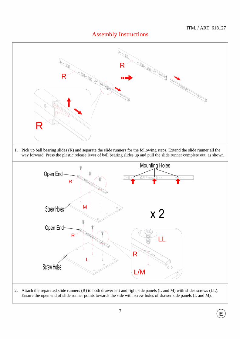
1. Pick up ball bearing slides (R) and separate the slide runners for the following steps. Extend the slide runner all the way forward. Press the plastic release lever of ball bearing slides up and pull the slide runner complete out, as shown.
2. Attach the separated slide runners (R) to both drawer left and right side panels (L and M) with slides screws (LL). Ensure the open end of slide runner points towards the side with screw holes of drawer side panels (L and M).
R
R
R
L
M
R
R
L/M
R
LL

ITM. / ART. 618127
8 E
Assembly Instructions
3. Securely screw six cam bolts (FF) into the plastic bushings on one drawer front (K), as shown.
4. Attach drawer side panels (L and M) to the drawer front (K) with four small wood dowels (JJ) and six small cam
locks (EE) making sure the grooves face inward and line up with each other. (Refer to page 2 on Cam Lock system operation supplement).
5. Slide drawer bottom panel (O) into the grooves between the drawer side panels (L and M) until fully inserted into the drawer front (K), as shown.
FF
K
K
K
L
M
EE
EE
JJJJ
JJJJ
KL
M
O

ITM. / ART. 618127
9 E
Assembly Instructions
KL
MO
N
KL
MO
N
KK
KK
6. Attach one drawer back panel (N) to the drawer side panels (L and M) with six long screws (KK) as shown. Tighten
all the screws with a Phillips head screwdriver.
7. Attach the drawer pull (MM) to the outside of the drawer front (K) with the provided bolts (NN) using a Phillips head screwdriver.
8. Repeat the same procedure to assemble the other drawer.
9. Attach the separated slide tracks (R) to both sides of Drawer Partition (F) with three slides screws (LL) per slide track. Make sure that the slide opening is against the front edge as shown.
KMM
NN
FF
LLLL
RR
ITM. / ART. 618127
10 E
Assembly Instructions
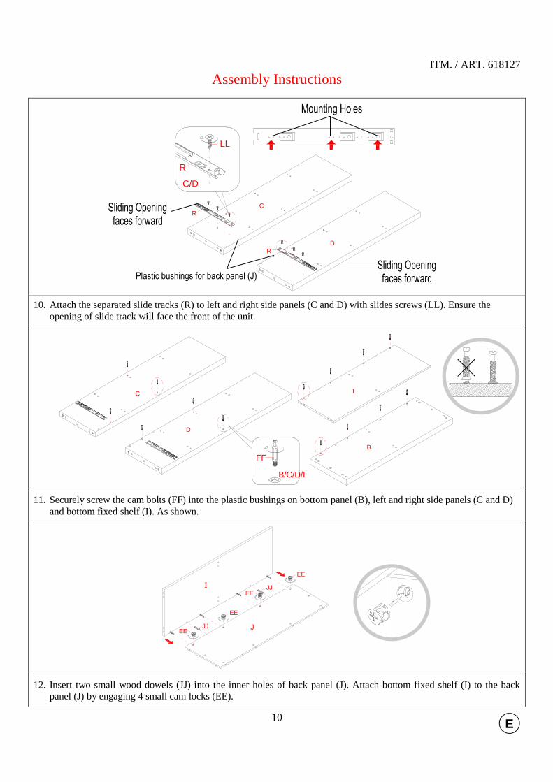
10. Attach the separated slide tracks (R) to left and right side panels (C and D) with slides screws (LL). Ensure the opening of slide track will face the front of the unit.
11. Securely screw the cam bolts (FF) into the plastic bushings on bottom panel (B), left and right side panels (C and D) and bottom fixed shelf (I). As shown.
12. Insert two small wood dowels (JJ) into the inner holes of back panel (J). Attach bottom fixed shelf (I) to the back panel (J) by engaging 4 small cam locks (EE).
J
I
JJEE
JJEE
EE
EE
C
D
R
R
C/D
R
LL
FF
B/C/D/I
C
D
I
B

ITM. / ART. 618127
11 E
Assembly Instructions
13. Attach drawer partition panel (F) to bottom fixed shelf (I) with four medium wood dowels (II). As shown.
14. Attach two divider panels (E) the assembled bottom fixed shelf (I) using four medium wood dowels (II).
15. Attach two divider panels (E) and middle fixed shelf (H) to the assembled divider panels (E) using eight large wood dowels (HH).
16. Proceed to install the remaining divider panels (E) and upper fixed shelf (G) to the assembled divider panels (E) using eight large wood dowels (HH). As shown.
HH
HH
HH
HH
J
IF
E
E
H
E
E
HH
HH
HH
HH
E
E
E
E
E
E
J
IF
H
G
J
I
F
II
II
J
I F
E
E
II
II
II
II

ITM. / ART. 618127
12 E
Assembly Instructions
17. Insert 20 large wood dowels (HH) into the end holes of fixed shelves (G, H and I) and 4 small wood dowels (JJ) to back panel (J) at both ends. DO NOT put dowels into the cam bolt holes.
18. Using the wood dowels as a guide, attach side panels (C and D) to the assembled unit with 4 large cam locks (DD) and 2 small cam locks (EE).
19. Insert 6 X-large wood dowels (GG), 4 large wood dowels (HH) and 2 small wood dowels (JJ) into the end holes of side panels (C and D), drawer partition panel (F) and back panel (J) respectively.
20. Attach bottom panel (B) to side panels (C and D) using four bolts (AA) with the lock washers (BB) and flat washers (CC) through the countersunk holes and screw into place.
21. Secure the back panel (J) to the bottom panel (B) by engaging 4 small cam locks (EE). 22. Cover the countersunk holes on bottom panel (B) with four plastic caps (QQ).
J
IF
H
G
C
D
HH
HH
HH
HH
HH
HH
HH
HH
HH
HH
JJ
JJ
JJ
JJ
EE
EEDD
DD
J
I FC
D
B
BC/DGG
QQCC
BBAA
B
J
EE
JJ
B
F
GG
GG
JJ
JJ
HH
HH
HH
ITM. / ART. 618127
13 E
Assembly Instructions
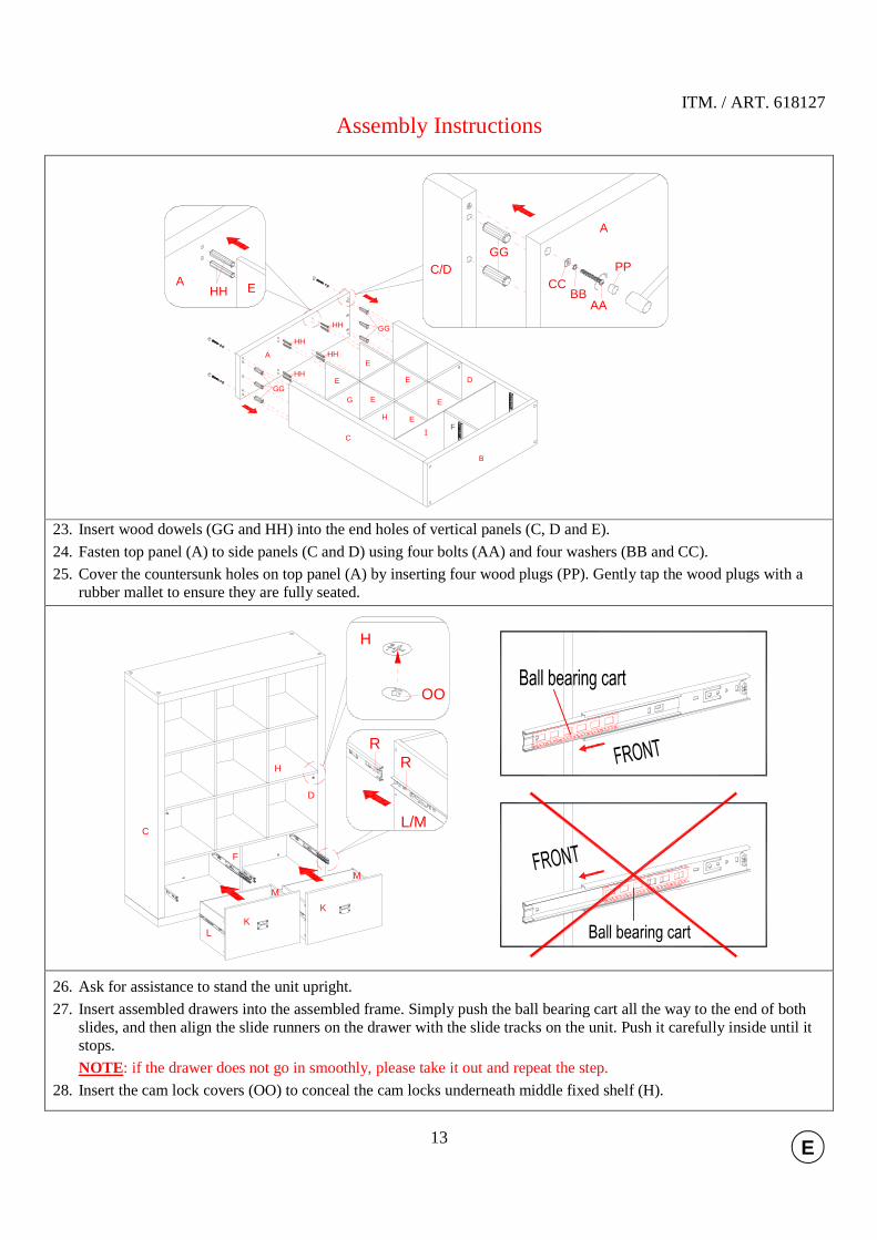
23. Insert wood dowels (GG and HH) into the end holes of vertical panels (C, D and E).
24. Fasten top panel (A) to side panels (C and D) using four bolts (AA) and four washers (BB and CC).
25. Cover the countersunk holes on top panel (A) by inserting four wood plugs (PP). Gently tap the wood plugs with a rubber mallet to ensure they are fully seated.
26. Ask for assistance to stand the unit upright.
27. Insert assembled drawers into the assembled frame. Simply push the ball bearing cart all the way to the end of both slides, and then align the slide runners on the drawer with the slide tracks on the unit. Push it carefully inside until it stops.
NOTE: if the drawer does not go in smoothly, please take it out and repeat the step.
28. Insert the cam lock covers (OO) to conceal the cam locks underneath middle fixed shelf (H).
KL
M
K
M
C
F
D
L/M
RR
OO
H
H
E
E
E
E
E
H
G E
IF
B
C
D
A
GG
GG
A
C/DCC
BBAA
PPGG
A E
HH
HH
HH
HH
HH

ITM. / ART. 618127
14 E
Assembly Instructions
29. Unfold storage baskets (P) and then place basket flooring (Q) inside the open basket to ensure it remains square. Position storage baskets onto the compartments, as shown.
30. You can combine 2 or more units to create an attractive storage wall for your home.
Tools required: Phillips screwdriver, power drill, 9.5 mm drill bit and rubber mallet.
31. Position the unit at the desired location against a wall. Follow the instructions printed on the plastic bag containing the tipping restraint hardware to attach the tip-over restraints to the unit and the wall.
32. The unit is now ready for use.
A
P
Q
P

ITM. / ART. 618127
15 E
Care and Maintenance
� Use a soft, clean cloth that will not scratch the surface when dusting. � Use of furniture polish is not necessary. Should you choose to use polish, test first in an inconspicuous area. � Using solvents of any kind on your furniture may damage the finish. � Never use water to clean your furniture as it may cause damage to the finish. � Always use coasters under beverage glasses and flowerpots. � Liquid spills should be removed immediately. Using a soft clean cloth, blot the spill gently. Avoid rubbing. � Always use protective pads under hot dishes and plates. Heat can cause chemical changes that may create
spotting within the furniture finish. � Stains or marks from crayons or ink markers will be difficult to remove. � In the event that your furniture is stained or otherwise damaged during use, we recommend that you call a
professional to repair your furniture. � Check bolts/screws periodically and tighten them if necessary.
Further advice about wood furniture care
It is best to keep your furniture in a climate-controlled environment. Extreme temperature and humidity changes can cause fading, warping, shrinking and splitting of wood. It is advised to keep furniture away from direct sunlight as sun may damage the finish.
Proper care and cleaning at home will extend the life of your purchase. Following these important and helpful tips will enhance your furniture as it ages.
A touch-up pen has been provided to repair any small nicks or scratches that may occur during assembly or shipping.
We hope you enjoy your purchase for many years. Thank you for your purchase!
QUALITY GUARANTEE
We are confident that you will be delighted with your Bayside Furnishings® purchase.
Should this product be defective in workmanship or materials or fail under normal use, we will repair or replace it for up to one (1) year from date of purchase. Every Bayside Furnishings® product is designed to meet your highest expectations. We guarantee that you will immediately see the value of our fine furniture. This warranty gives you specific legal rights and you may also have other rights which vary from State to State.
AUSTRALIA: Our goods come with guarantees that cannot be excluded under the Australian Consumer Law. You are entitled to a replacement or refund for a major failure and for compensation for any other reasonably foreseeable loss or damage. You are also entitled to have the goods repaired or replaced if the goods fail to be of acceptable quality and the failure does not amount to a major failure.
Customer Service: 1-877-494-2536 (English, French and Spanish) Pacific Standard Time: 8:30 a.m. - 4:30 p.m., Monday to Friday
(In US, Canada, and Mexico only) www.baysidefurnishings.com
MADE IN CHINA / FABRIQUÉ EN CHINE / HECHO EN CHINA