Embed Size (px)
Citation preview

Welded Joint
• A Permanent joint
• What is Welding? (M.M.M.M.) • Brazing, Soldering, Adhesive - - -

Multi
Pass
Bead Weld

HAZ
Throat & Leg


Type of welded joints

SPECIFICATION OF WELD SYSTEM
The AWS standard welding symbol


Weldment Design Practice
Eliminate welding by forming the
plate and using rolled or extruded
sections
Minimise the amount of weld
metal
Do not over weld
Use intermittent welding in
preference to a continuous weld
pass
Avoid multiple weld accumulation
Metal to metal contact should
bear load, not the weld
Place welds about the neutral
axis
Balance the welding about the
middle of the joint by using a
double-V joint in preference to a
single-V joint

ARC AND GAS WELDING SYMBOLS

Fillet welds
(a) The number beside triangle indicates the leg size. The arrow
need to point only to one weld when the weld on all sides is
same.
(b) Here the weld symbol indicates that he weldment is
intermittent and staggered at 60 mm length at an interval of
200 mm (centre to centre distance).

Square butt welded on both
sides. Single V with 60o bevel and
root opening of 2 mm
Double V Single bevel
Different groove preparations for butt joints

Circle on the weld symbol indicates that the welding is to go
all around.
All arround fillet weld

T joint for thick plates U and J joints for thick plates
Corner weld, meant
only for light loads
Edge weld for sheet metal
and light loads
Different groove preparations for fillet joints

Typical butt joints with possible loading
/F hl /F hl
Reinforcements, though can increase the area taking the load, but for
fatigue loading, it induce stress concentration at location “A” and
hence normally removed by grinding or machining.

Typical fillet with possible loading
sincos
ht
sincos
2
45180sin45sin
cos
sin
hht
FF
FF
oo
n
s
Along any plain at angle

The stresses at any angle in the weld
hl
F
hl
F
tl
F
A
F ss
2sincossinsincossin
hl
F
hl
F
tl
F
A
F nn
cossincossincoscos 2
222222 cossinsincossincos3' hl
F
The resultant von-Mises stress is
sincos
ht
Largest von-Mises stress
occurs at = 62.5 degree

Final Formulas
hl
F
hl
F
hl
F
o
o
o
623.0
196.1
16.2'
,62.5at occurs stress Mises- vonmaximum The
5.62
5.62
5.62
'
max
0

Parallel Fillet Weld: Welding Code Method
/ 0.707 1.414 /F hl F hl
htFor
ht
707.0,45
sincos
0

Minimum Weld-Metal Properties
Table 9–3

Stresses Permitted by the AISC Code for Weld Metal
Table 9–4
a M = Fa
/V A
/Mr J
Primary shear stress:
Secondary shear stress:
Where:
22
areas weldment theof cetroid about the
weldments theof area ofmoment polar Second
iiiyyxxiiG rAIIrAJ
J
i
WELDED JOINT IN TORSION
21
22 )(

An example of
unequal weld
2- weldmentof size leg
1- weldmentof size leg
707.0
707.0
2
1
22
11
h
h
hd
hb
btdtAAA 2121
The total throat area against primary shear
Secondary shear estimation needs the estimation of the total
second polar moment of area of the two weldments together.
1212
;12
;12
1212;
12;
123
2
3
2
22
3
2
2
3
2
2
3
1
3
1
11
3
1
1
3
1
1
2
1
btbtIIJ
btI
btI
dtdtIIJ
dtI
dtI
yxGyx
yxGyx

The centroid G can be
located as follows.
A
yAyAy
A
xAxAx
2211
2211
2
22
2
11
2
2
2
22
22
11
21
;
rAJrAJJ
yyxxryxxr
GG
An example of unequal weld

Torsional Properties of Fillet Welds
(Table 9-1, page:484)
uhJJ 707.0
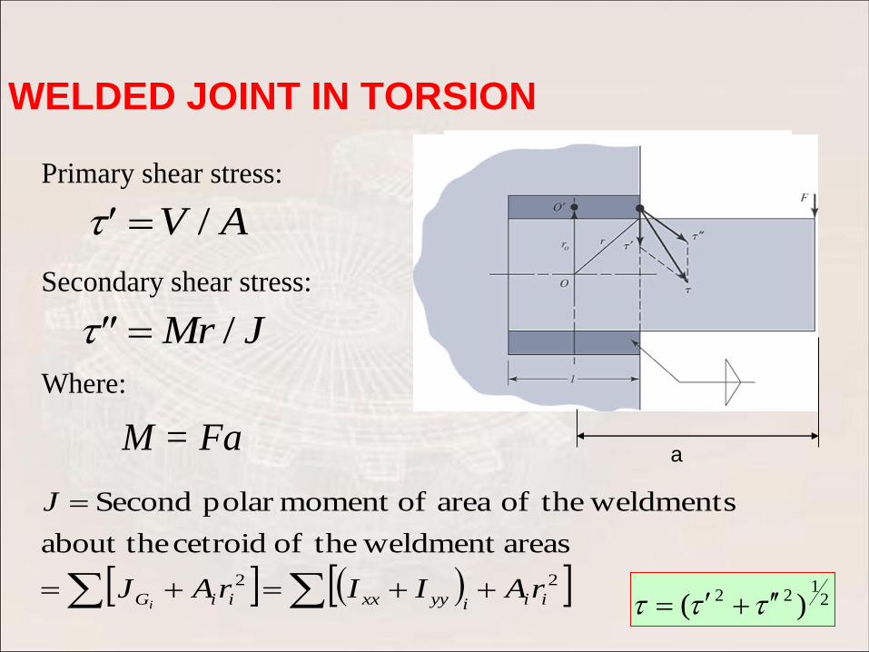
BENDING WELDED JOINT
A
V' stress,shear Primary
bdh
M
hbd
Md
I
Mc
bdhhII
bdI uu
414.1
2/707.0
2/
stressshear Secondary
2707.0707.0 ,
2
2
22
21
22 )( Combining

Bending Properties of Fillet Welds
(Table 9-2; page:488-489)
uhII 707.0

Bending Properties of Fillet Welds - contd….
(Table 9-2;
page:488-489)

Welded Joint under Fatigue loading
Conventional methods will be used
In fatigue, the Gerber criterion is best; however,
Goodman criterion is commonly used for simplicity.
For the surface factor, forged surface will be assumed for
weld unless a superior finish is specified.
For stress concentration factor use Table 9.5

Fatigue Stress-Concentration Factors, Kfs
Table 9–5