Embed Size (px)
Citation preview

OPERATIONAL MANUAL
MODEL: 8MM DUCT RODDER
by BLUEROCK ® Tools
Volume
1.1

M W S - 8 M M D U C T R O D D E R
© THE NEWMAN TRADING COMPANY LLC DBA BLUEROCK® TOOLS 2016 1100 SW 16th St • Suite D
Renton, WA 98057 Phone 206.604.8363 • Fax 425.572.5167
www.bluerocktools.com

8 M M D U C T R O D D E R
TableofContents
SAFETY 1PRE-OPERATIONAL SAFETY CHECKS 1OPERATIONAL SAFETY CHECKS 1
SPECIFICATIONS 3
OPERATIONS 4PURPOSE 4INSTALLATION 4OPERATIONAL PRINCIPLES 4
CONDUITSIZECHART 5
8 M M D U C T R O D D E R
1
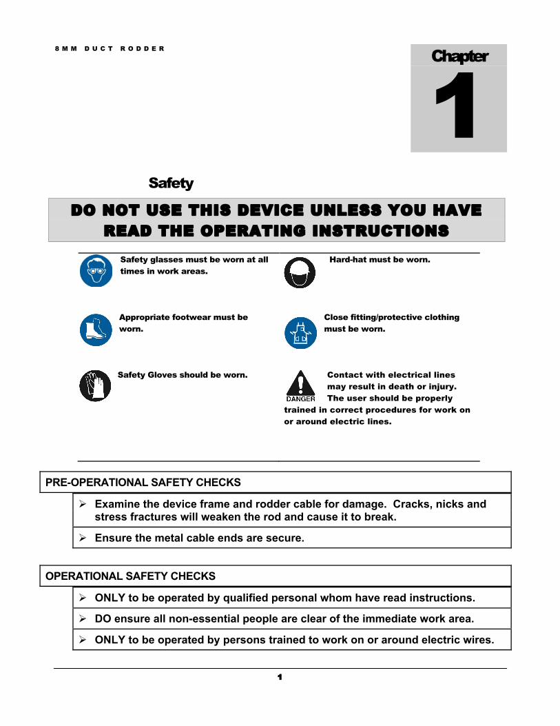
Safety
DO NOT USE THIS DEVICE UNLESS YOU HAVE READ THE OPERATING INSTRUCTIONS
Safety glasses must be worn at all times in work areas.
Hard-hat must be worn.
Appropriate footwear must be worn.
Close fitting/protective clothing must be worn.
Safety Gloves should be worn. Contact with electrical lines may result in death or injury. The user should be properly
trained in correct procedures for work on or around electric lines.
PRE-OPERATIONAL SAFETY CHECKS
Ø Examine the device frame and rodder cable for damage. Cracks, nicks and stress fractures will weaken the rod and cause it to break.
Ø Ensure the metal cable ends are secure.
OPERATIONAL SAFETY CHECKS
Ø ONLY to be operated by qualified personal whom have read instructions.
Ø DO ensure all non-essential people are clear of the immediate work area.
Ø ONLY to be operated by persons trained to work on or around electric wires.
Chapter
1

8 M M D U C T R O D D E R
2
Ø DO NOT operate machine outside of device specifications.
Ø DO be mindful to only feed cable out using the eye on the frame. Failure to do this could result in injury from rodder coming out too quickly or quickly snapping out towards the users.
Ø DO NOT allow children or untrained personal near device.
Ø DO NOT use on live electrical circuits.
Ø DO NOT bend beyond maximum allowable bending radius.
Ø DO keep secure footing to protect yourself from the possibility of a fall should the rod break or pulling eye move suddenly.
Ø DO NOT use pliers or powered pulling equipment with rod as damage may occur to rod.
Ø DO keep rod inside metal frame when not in use.
Ø DO NOT force a pull that is not moving. Remove wires and device and check for obstructions.
Ø DO NOT pull rod over sharp edges as damage may occur.
Ø DO wear protective safety glasses/face shield, protective clothing, hard hat, proper shoes when operating, servicing, or transporting device.
Ø DO keep work area free of debris.
Ø DO be mindful that when the rod is coiled it is like a large spring. The stored energy can be very strong when unleashed. Do not attempt to use rod without a frame or reel. Uncontained rod can whip around and cause damage to persons or property.
Ø DO keep rod clean of contaminants that may damage the rod including water which can also be conductive of electricity.
Ø DO NOT store the rodder in excessive heat. It will cause the rod to kink or snap.

8 M M D U C T R O D D E R
3
Specifications 8MM RODDER Diameter 8mm (0.31”) Length 260 Meters (850’) Color Yellow Length Markers Every 1 meter starting at 1 meter
RODDER CABLE DATA Reinforcement E-Glass Fiber Inner Glass Content 80-85% Material of Pulling Rod Epoxy Fiberglass (inner) and High Density
Polyethylene (outer) Density >150g/m Diameter Tolerance ±0.10mm Minimum Pulling Strength 4000N ±5% Tensile Modulus >45 MPa Consistency of Rod 150g ±5% Flexural Modulus >45 MPa Elongation at Break 2.5-3% Polyethylene Cover Medium Density Polyethylene Resin Tensile Strength >150N Strength & Crack Resistance >1000 hr
Chapter
2
8 M M D U C T R O D D E R
4
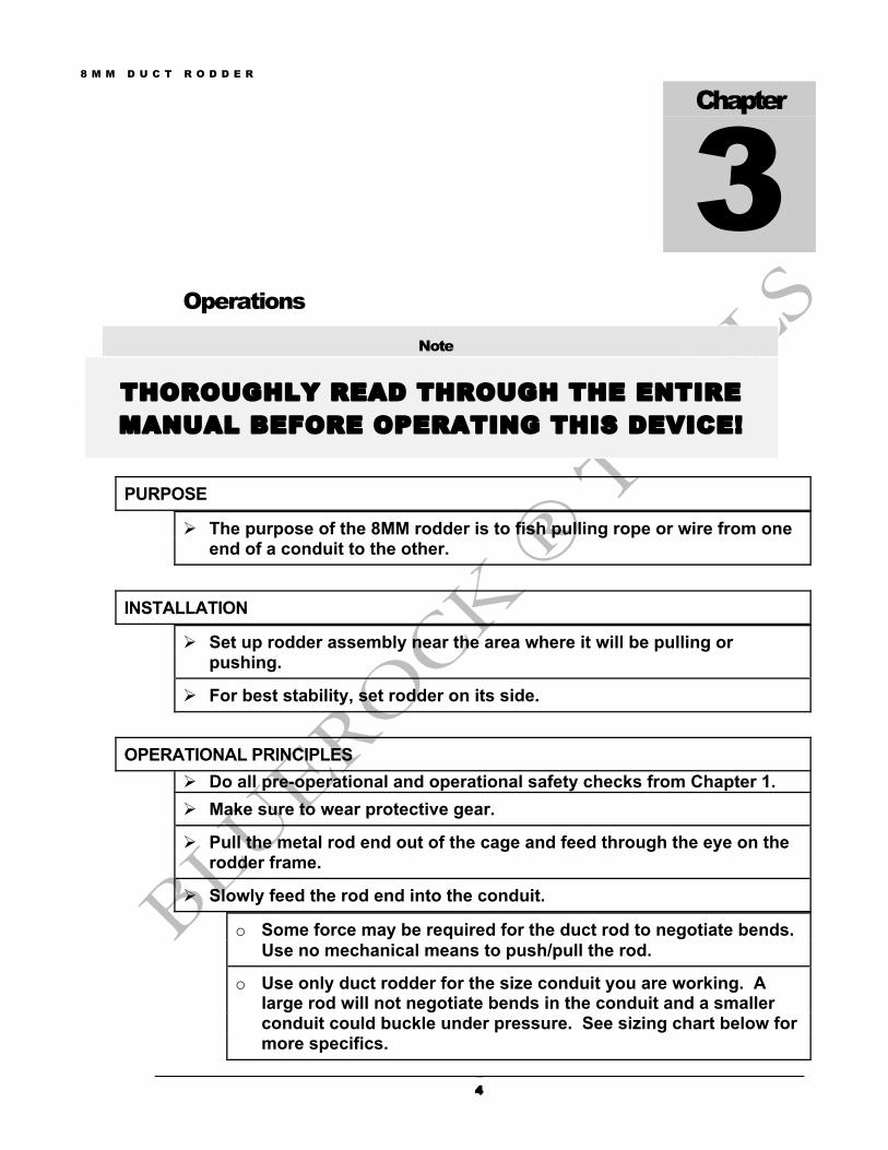
Operations
Note
THOROUGHLY READ THROUGH THE ENTIRE MANUAL BEFORE OPERATING THIS DEVICE!
PURPOSE
Ø The purpose of the 8MM rodder is to fish pulling rope or wire from one end of a conduit to the other.
INSTALLATION
Ø Set up rodder assembly near the area where it will be pulling or pushing.
Ø For best stability, set rodder on its side.
OPERATIONAL PRINCIPLES Ø Do all pre-operational and operational safety checks from Chapter 1. Ø Make sure to wear protective gear.
Ø Pull the metal rod end out of the cage and feed through the eye on the rodder frame.
Ø Slowly feed the rod end into the conduit.
o Some force may be required for the duct rod to negotiate bends. Use no mechanical means to push/pull the rod.
o Use only duct rodder for the size conduit you are working. A large rod will not negotiate bends in the conduit and a smaller conduit could buckle under pressure. See sizing chart below for more specifics.
Chapter
3
8 M M D U C T R O D D E R
5
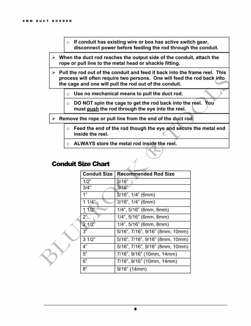
o If conduit has existing wire or box has active switch gear, disconnect power before feeding the rod through the conduit.
Ø When the duct rod reaches the output side of the conduit, attach the rope or pull line to the metal head or shackle fitting.
Ø Pull the rod out of the conduit and feed it back into the frame reel. This process will often require two persons. One will feed the rod back into the cage and one will pull the rod out of the conduit.
o Use no mechanical means to pull the duct rod.
o DO NOT spin the cage to get the rod back into the reel. You must push the rod through the eye into the reel.
Ø Remove the rope or pull line from the end of the duct rod.
o Feed the end of the rod though the eye and secure the metal end inside the reel.
o ALWAYS store the metal rod inside the reel.
Conduit Size Chart Conduit Size Recommended Rod Size 1/2” 3/16” 3/4” 3/16” 1” 3/16”, 1/4” (6mm) 1 1/4” 3/16”, 1/4” (6mm) 1 1/2” 1/4”, 5/16” (6mm, 8mm) 2” 1/4”, 5/16” (6mm, 8mm) 2 1/2” 1/4”, 5/16” (6mm, 8mm) 3” 5/16”, 7/16”, 9/16” (8mm, 10mm) 3 1/2” 5/16”, 7/16”, 9/16” (8mm, 10mm) 4” 5/16”, 7/16”, 9/16” (8mm, 10mm) 5” 7/16”, 9/16” (10mm, 14mm) 6” 7/16”, 9/16” (10mm, 14mm) 8” 9/16” (14mm)