Embed Size (px)
Citation preview

CS 7600
Installation Guide

Notice
CARESTREAM Systems are designed to meet international safety and performance standards. Personnel operating the unit must have a thorough understanding of the proper operation of the system. This guide has been prepared to aid personnel in system installation. Do not operate the system before reading this guide and the CS 7600 User Guide for gaining a clear understanding of the operation of the system. If any part of this guide is not clear, please contact your Carestream Health representative for clarification.
The CS 7600 is intended for digital dental radiography using an imaging plate (storage phosphor screen) for radiographic diagnostic intraoral images.
The CS 7600 in addition, optionally provides the Scan & Go technology to enable dental practitioners prior to acquisition to record the dental imaging plates with exam acquisition data.
U.S. Federal law restricts this device to sale by or on the order of a dentist or physician.
This document is originally written in English.
No part of this guide may be reproduced without the express permission of Carestream Health, Inc.
Guide Name: CS 7600 Installation Guide Part Number: 8J6395 Revision Number: 01 Print Date: 2011-08
In this guide, all trademarks and registered trademarks are the property of their respective holders.The brand names and logos reproduced in this guide are copyright.CS 7600, complies with Directive 93/42/CEE relating to medical equipment.
Manufacturer
Authorized Representative in the European Community
Carestream Health France
COPERNIC II
Immeuble Le Neptune
1, Rue Galilée
93192 Noisy-Le-Grand
FRANCE
WARNING: Read the “Safety, Regulatory and the Technical Specifications User Guide” and make sure you observe all the Warnings and Cautions before using the CS 7600.
0086
Carestream Health, Inc.150 Verona StreetRochester NY 14 608
EC REP

Contents
Chapter 1 Conventions in this Guide
Conventions in this Guide. . . . . . . . . . . . . . . . . . . . . . . . . . . . . . .1
Chapter 2 CS 7600 System Overview
Introduction . . . . . . . . . . . . . . . . . . . . . . . . . . . . . . . . . . . . . . . . . . . .3
CS 7600 Components Overview. . . . . . . . . . . . . . . . . . . . . . . . .4
Scanner Overview. . . . . . . . . . . . . . . . . . . . . . . . . . . . . . . . . . .4
Smart Imaging Plates Overview . . . . . . . . . . . . . . . . . . . . . .6
Hygienic Sheaths . . . . . . . . . . . . . . . . . . . . . . . . . . . . . . . . . . .8
Scan & Go Overview . . . . . . . . . . . . . . . . . . . . . . . . . . . . . . .9
Shelf . . . . . . . . . . . . . . . . . . . . . . . . . . . . . . . . . . . . . . . . . . . . 10
Chapter 3 CS 7600 Systems Packaging
CS 7600 Systems Description . . . . . . . . . . . . . . . . . . . . . . . . 11
Packaging of CS 7600 System. . . . . . . . . . . . . . . . . . . . . . . . 11
Box Components . . . . . . . . . . . . . . . . . . . . . . . . . . . . . . . . . . . . . 11
Chapter 4 Site Preparation Before Installation
Environmental Requirements . . . . . . . . . . . . . . . . . . . . . . . . . . . 13
Electrical Requirements. . . . . . . . . . . . . . . . . . . . . . . . . . . . . . . . 14
Minimum System Requirements . . . . . . . . . . . . . . . . . . . . . . . . 14
Networking Requirements. . . . . . . . . . . . . . . . . . . . . . . . . . . . . . 14
Chapter 5 Software Installa-tion
Installing the KODAK Dental Imaging Software . . . . . . . . . . 16
Installing the CS 7600 Acquisition interface . . . . . . . . . . . . 21
Installing the Scan & Go Device. . . . . . . . . . . . . . . . . . . . . . . 26
Uninstalling the CS 7600 Acquisition interface . . . . . . . . . . 28
Chapter 6 Setting Up the CS 7600
CS 7600 Setup Configuration Options . . . . . . . . . . . . . . . . . 29
Single Scanner and Single Computer . . . . . . . . . . . . . . . 29
Single Scanner, Single Computer and Scan & Go Device . . . . . . . . . . . . . . . . . . . . . . . . . . . . . . . 30
Single Scanner, Multiple Computers Setup . . . . . . . . . . 30
Single Scanner, Multiple Computers with Multiple Scan & Go Devices. . . . . . . . . . . . . . . . . . . . . . . 31
Setting Up Procedures. . . . . . . . . . . . . . . . . . . . . . . . . . . . . . . . 32
Setting Up Single Scanner, Single Computer, Scan & Go Device . . . . . . . . . . . . . . . . . . . . . . . . . . . . . . . 32
Setting Up Single scanner, Multiple Computers, Scan & Go Device . . . . . . . . . . . . . . . . . . . . . . . . . . . . . . . 36
Setting Up Network Connections, Windows XP. . . . 40
Setting Up Network Connections, Windows 7 . . . . 43
CS 7600_Installation Guide (8J6395)_Ed01 i

Scanner Manual IP Setup . . . . . . . . . . . . . . . 47
Scanner Setup . . . . . . . . . . . . . . . . . . . . . . . . . . . . . . . . . . . . . . . 49
Scan & Go Device Setup . . . . . . . . . . . . . . . . . . . . . . . . . . . . . 51
Imaging Processing Adjustment . . . . . . . . . . . . . . . . . . . . . . . . 53
Configuring the DICOM Character Set Encoding . . . . . . . . 54
Image Quality Control . . . . . . . . . . . . . . . . . . . . . . . . . . . . . . . . . 55
Required Tools. . . . . . . . . . . . . . . . . . . . . . . . . . . . . . . . . . . . 55
Pre-requisites . . . . . . . . . . . . . . . . . . . . . . . . . . . . . . . . . . . . . 55
Image Quality Control Procedure . . . . . . . . . . . . . . . . . . . 55
Defining the X-ray and CS 7600 Acquisition interface Settings . . . . . . . . . . . . . 55
Preparing the QC tool . . . . . . . . . . . . . . . . . 56
Performing the X-ray . . . . . . . . . . . . . . . . . . 57
Scanning the Imaging Plate . . . . . . . . . . . . . . 58
Evaluating Image Quality . . . . . . . . . . . . . . . . 58
ii

1 Conventions in this Guide
Conventions in this GuideThe following special messages emphasize information or indicate potential risk to personnel or equipment:
WARNING: Warns you to avoid injury to yourself or others by following the safety instructions precisely.
CAUTION: Alerts you to a condition that might cause serious damage.
Important: Alerts you to a condition that might cause problems.
Note: Emphasizes important information.
Tip: Provides extra information and hints.
CS 7600_Installation Guide (8J6395)_Ed01 1

2 Chapter 1 Conventions in this Guide

2 CS 7600 System Overview
Introduction
CS 7600 is a scanner system for intraoral X-ray exposed imaging plates.
The CS 7600 is intended for digital dental radiography using an imaging plate (storage phosphor screen) for radiographic diagnostic intraoral images. Use the CS 7600 system to scan and review intraoral dental X-ray images. When scanning the X-ray exposed imaging plate a digital image is previewed on the scanner’s LCD and saved to the scanner’s internal memory. After scanning, the scanner erases the imaging plate and ejects it. The imaging plate is ready for re-use.
The exam acquisition’s scanned image is sent over the network to the workstation’s Acquisition interface. Using the Acquisition interface the image is processed and reviewed.
The Acquisition interface sends the images to the Kodak Dental Imaging Software, which archives the acquired images.
The scanner connects directly to the network, or is connected peer-to-peer to the workstation.
The scanner can be optionally mounted on a wall, or placed on a desk/counter top using a special shelf (adapter).
The system is composed of the following elements:
• CS 7600 scanning device (page 4)
• Smart imaging plates (page 6)
• CS 7600 Acquisition interface (page 11)
• Scan & Go device (optional, page 45)
Note: The CS 7600 is intended for dental professionals. You are required to have training to use the CS 7600.
Note: The scanner is supplied with a separate viewing and archiving software package: Kodak Dental Imaging Software, approved by Carestream Health.
Note: The CS 7600 User Guide is also provided as a PDF file on the supplied CD-ROM.
CS 7600_Installation Guide (8J6395)_Ed01 3

CS 7600 Components Overview
Scanner Overview
The CS 7600 scanner includes the functions necessary for scanning and acquiring images from the imaging plates.
Figure 1 CS 7600 Front View
1 3.5" QVGA color LCD (320 X 240 pixels, landscape matrix)
2 Function buttons for menus
3 On/Off button + power indication LED. On/Off button functions:
• Turn scanner On: press for 1 second
• Shut down (close application and files and then turn off): press for 2 seconds.
4 Base
5 Intraoral imaging plates tray
6 Detachable insertion panel. The CS 7600 makes use of two insertion panel sizes according to the inserted imaging plates size (0–3 or 4).
7 Front cover
8 Back covers
2
7
8
3
6
1
4
5
4 Chapter 2 CS 7600 System Overview

Figure 2 CS 7600 Rear View
Figure 3 Cables Compartment in detail
1 Service door
2 Base
3 Cables compartment for power supply connection and interface ports (RJ-45 Ethernet port)
4 Back cover
1
4
3
2
1
3
2
4
1 Power supply inlet
2RJ-45 Ethernet port (Ethernet activity LEDs: yellow indicates speed, green indicates link status)
3 Service ONLY ports
4 Compartment cover
CS 7600_Installation Guide (8J6395)_Ed01 5

Smart Imaging Plates Overview
The CS 7600 works with five imaging plate sizes: 0 to 4. The scanned image file size depends on the imaging plate size and the scanning resolution set by the user.
The smart function of the imaging plates is utilized when using the Scan & Go device.
Table 2-1 Intraoral imaging plates sizes
Size Illustration Application
0 Periapical exam (Pediatric dentistry)
1 Bitewing exam (Pediatric dentistry)
2 Periapical exam (Adult)
3 Bitewing exam (Adult)
4 Occlusal exam
6 Chapter 2 CS 7600 System Overview

The imaging plate has two sides: the active side for capturing the X-ray image and the inactive side. The active side of the imaging plate includes an orientation mark ‘c’ to facilitate accurate positioning within the patients’ mouth. The inactive side has a printed dot that corresponds to the location of the orientation mark on the active side. This dot is visible through the transparent hygienic sheath and is helpful too in correct positioning of the imaging plate in the patient’s mouth.
Inactive side
Active side
C
Important: Use only Carestream imaging plates and hygienic sheaths!
CS 7600_Installation Guide (8J6395)_Ed01 7

Hygienic Sheaths
For each imaging plate size there is a corresponding one-time use, disposable, hygienic sheath for preventing cross contamination. The transparent side allows viewing the orientation mark for positioning the imaging plate correctly in the patient’s mouth while the opaque side protects the active side of the inserted imaging plate from light damaging effects. The foam strip is a stopper that prevents inserting the hygienic sheath by mistake into the scanner (as long as the insertion direction is correct).
Figure 4 Hygienic Sheath (front view)
1 Adhesive strip (for sealing the hygienic sheath)
2 Foam stopper
3 Sheath transparent and light protection barrier
3
1
2
8 Chapter 2 CS 7600 System Overview

Scan & Go Overview
Scan & Go is an optional device that enables you to link the imaging plate to a specific exam acquisition (e.g. patient) prior to acquisition. This information is retrieved by the scanner and the imaging plate is scanned automatically according to this information (resolution, target workstation, etc.). Scanned images are then routed automatically to the correct workstation, associated to the correct exam acquisition and placed in the correct frame in the CS 7600 Acquisition interface.
1 USB 2.0 port
2 On/Off button
3 On/Off/Recording status indicator LED (blue)
Turning On/Off, 3 short flashes
Standby (intermittent flashing)
Recording data to the imaging plate (successive short flashes)
4 Battery status indicator LED (amber):
Charging (static light)
Low battery (successive short flashes)
(light Off) battery charged
5 Recording surface for imaging plate
6 Mounting adapter
5
1
4
3
2
6
CS 7600_Installation Guide (8J6395)_Ed01 9

Shelf
The CS 7600 can be optionally mounted on the wall using an adapter.
10 Chapter 2 CS 7600 System Overview

3 CS 7600 Systems Packaging
CS 7600 Systems DescriptionCS 7600 Systems are available in 2 configurations:
• CS 7600 System with Scan & Go device OR
• CS 7600 System
Packaging of CS 7600 SystemCS 7600 System packaging is composed of the following boxes:
• CS 7600 system box (box A), see page 11.• Dependent on ordered configuration: The Scan & Go pack (box B), see page 12.
Box Components
Table 3-1 Box A Components
Product Comments
CS 7600 system
Intraoral imaging plates tray Removable collection tray
Smart imaging plates starter kit Two size 2 imaging plates, and two size 0 imaging plates.
CS 7600 hygienic sheaths size 2 1 package of 200 hygienic sheaths
CS 7600 hygienic sheaths size 0 1 package of 200 hygienic sheaths
CS 7600 Regulatory and Safety guide
CS 7600 Installation Guide
Quick reference guide poster
CS 7600 installation CD Acquisition interface, and User Guide in PDF format.
Insertion slot for size 4 imaging plates
CS 7600 imaging plates transport box
CS 7600 imaging plates pad
CS 7600 power supply External, 24 V (dc)
One country-specific power cord EU/US/Japan
RJ-45 Ethernet cable 3 meters
Crossover network cable 3 meters
CS 7600_Installation Guide (8J6395)_Ed01 11

Table 3-2 Box B Components
Product Comments
Scan & Go license card Number of supplied licenses on card according to order
Scan & Go device Number of devices corresponding to the number of licenses
USB cable Number of cables corresponding to the number of Scan & Go devices
12 Chapter 3 CS 7600 Systems Packaging

4 Site Preparation Before Installation
Environmental RequirementsCheck the following ambient operating condition requirements of the room before installing the unit:
Temperature: 5–35 °C
Relative humidity: 30–85 % Non-condensing
Atmospheric pressure: 700–1060 hPa
For optimal results it is recommended that room light is less than 500 lux to minimize the imaging plates exposure to light.
The unit dimensions illustrated in the above figure are as follows:
• Height of the unit (267 mm)
• Width (237 mm) and depth (260 mm) of the unit
260 mm
237 mm
270
mm
CS 7600_Installation Guide (8J6395)_Ed01 13

Electrical Requirements
Minimum System RequirementsFollow the CS 7600 Safety, Regulatory & Technical Specification Guide for the minimum computer system requirements for CS 7600 intraoral imaging software. If necessary you must update your computer system configuration.
Networking RequirementsIf the site implements a network configuration and not a direct peer-to-peer connection, the site must have an available RJ-45 network socket for plugging in the scanner. The workstation computer must meet the minimum computer requirements as specified in the Safety, Regulatory & Technical Specifications User Guide.
Table 4-1 Electrical installation specifications
Electrical Installation specifications
Power Supply 100 V AC – 240 V AC 1.5 A
Frequency 50/60 Hz
UPS (online, recommended) 700 VA (UPS is connected to the CR system, computer and monitor)
Important: It is MANDATORY to check that the computer system configuration is compatible with the computer minimum system requirements specified in the Safety, Regulatory and the Technical Specifications User Guide. If necessary you must update your computer system configuration.
Important: The scanner cannot connect to a computer through wireless communication.
14 Chapter 4 Site Preparation Before Installation

5 Software Installation
Important: In order to install the Kodak Dental Imaging Software and CS 7600 Acquisition interface you must have administrator privileges.
Important: To enable sending images by the Kodak Dental Imaging Software to a central database, all workstations need to be in the same workgroup.
Important: Do not connect the Scan & Go device before you have installed the KODAK Dental Imaging Software and the Acquisition interface.
CS 7600_Installation Guide (8J6395)_Ed01 15

Installing the KODAK Dental Imaging SoftwareBefore installing the KODAK Dental Imaging Software, check that:
• The computer has all the system requirements• You have the software DVD as of KODAK Dental Imaging Software version 6.12.19 or
higher
To install the KODAK Dental Imaging Software, follow these steps:
1 Insert the software DVD in the DVD-ROM drive of the computer.
Wait for the installation program to start. If the program does not start automatically, click Start >
Run and enter D:\setup.exe if D is the letter for the DVD-ROM drive, or the letter of the relevant
drive on the computer.
2 The Choose Setup Language dialog box is displayed. Select the installation language and click OK.
3 The Kodak Dental Imaging Software welcome page and the InstallShield wizard are displayed.
16 Chapter 5 Software Installation

4 The Welcome to KODAK Dental Imaging Software Installation dialog box is displayed. Click Next to launch the installation.
5 The License Agreement dialog box is displayed. Accept and click Yes.
CS 7600_Installation Guide (8J6395)_Ed01 17

6 The Choose Destination Location dialog box is displayed. Click Next if you accept the default destination folder (c:\program files\Kodak\Kodak Dental Imaging Software) or browse to choose another destination folder.
7 The KODAK Dental Imaging Software dialog box is displayed. The Patient file is selected by default.
8 The following dialog box is displayed. Keep the defaults and click Next to begin the installation.
18 Chapter 5 Software Installation
The InstallShield Wizard is displayed. Let the installation process run automatically.
The Kodak Patient file - InstallShield Wizard is displayed while the patient files are installed on
the hard drive.
The CS 7600 InstallShield Wizard launches the installation.
If the firewall is active, the Windows Security Alert dialog box is displayed. Click Unlock.
CS 7600_Installation Guide (8J6395)_Ed01 19

9 The Installation Complete dialog box is displayed when the installation is finished. Click Finish.
The is installed on your desktop.
20 Chapter 5 Software Installation
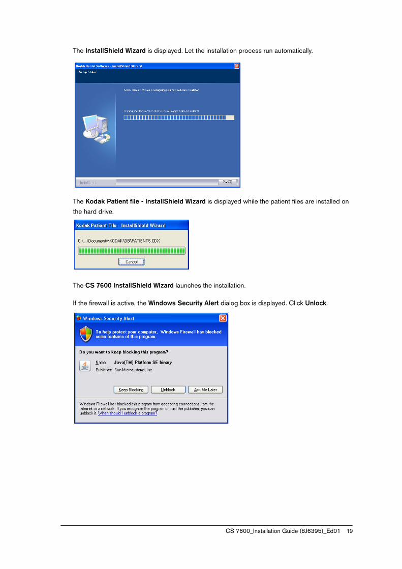
Installing the CS 7600 Acquisition interface
Before installing the CS 7600 Acquisition interface check that:
• The computer has all the computer system requirements (refer to the CS 7600 Safety, Regulatory & Technical Specification Guide).
• You have the software CD.
To install the CS 7600 Acquisition interface, follow these steps:
1 Insert the installation CD shipped with the system in the CD-ROM drive of the computer.
2 The CS 7600 Acquisition interface InstallShield wizard launches the installation. Click Install.
The CS7600 - InstallShield Wizard is displayed while the installation is setup.
Important: The KODAK Dental Imaging Software must be installed prior to installing the CS 7600 Acquisition interface.
Important: In order to install the CS 7600 Acquisition interface you must have administrator privileges.
CS 7600_Installation Guide (8J6395)_Ed01 21

3 The Welcome to the Carestream Wizard for CS7600 dialog box is displayed. Click Next to launch the installation.
4 The Destination Folder dialog box is displayed. Click Next if you accept the default destination folder (C:Program Files/CSH/CS7600\), or browse to choose another destination folder.
22 Chapter 5 Software Installation

5 The Room -Workstation name dialog box is displayed. Enter the room or workstation name. By default the field is populated with <workstation name_user name>. Click Next.
6 The Ready to Install the Program dialog box is displayed. Click Install to start the installation of the Acquisition interface.
CS 7600_Installation Guide (8J6395)_Ed01 23

7 Let the installation process run automatically.
8 The installation includes installing the driver. Click Install.
9 When the driver installation is completed, a confirmation message will be displayed. Click OK.
24 Chapter 5 Software Installation
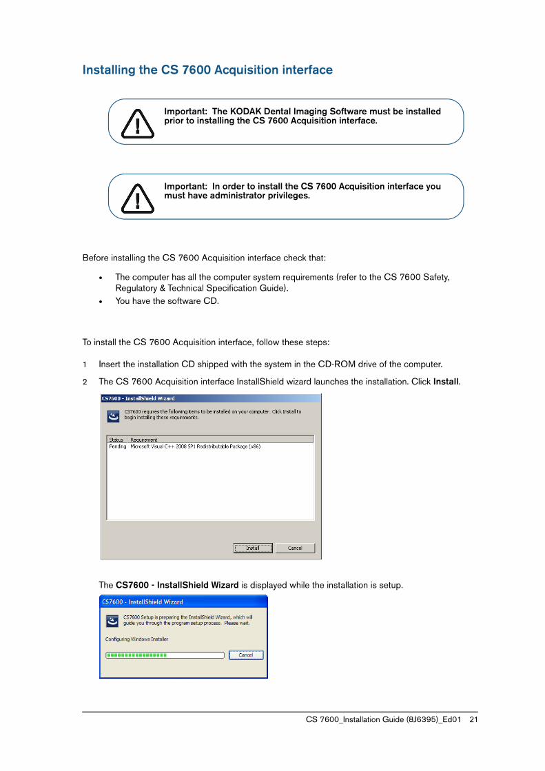
10 The Carestream Wizard Completed dialog box is displayed when the installation is finished. Click Finish.
Note: It is recommended to upgrade to the latest software version whenever possible. Updates are posted at: http://infotec.carestreamdental.com
CS 7600_Installation Guide (8J6395)_Ed01 25

Installing the Scan & Go Device For CS 7600 configurations that include the optional Scan & Go device, install the Scan & Go driver at each workstation where you install a Scan & Go device.
To install the Scan & Go driver, follow these steps:
1 Connect the Scan & Go device USB cable to a workstation USB port.
The Scan & Go device’s amber LED lights up to indicate it is charging and the Found New Hardware Wizard starts.
2 Select the No, not this time option and then click Next.
Important: Before installing the Scan & Go driver and device, make sure each workstation has the following software installed:
• KODAK Dental Imaging Software
• Acquisition interface
26 Chapter 5 Software Installation

3 Select the Install the software automatically option and then click Next.
4 The Wizard conducts a search for the Scan & Go device software.
5 While the Wizard searches or installs, the Windows Logo testing message is displayed.
Click Continue Anyway.
CS 7600_Installation Guide (8J6395)_Ed01 27

6 The Installation screen is displayed.
7 When the software installation is finished, the Completing the Found New Hardware Wizard dialog box is displayed.
Click Finish to complete the Scan & Go device installation.
Uninstalling the CS 7600 Acquisition interfaceIf for some reason you need to uninstall the CS 7600 Acquisition interface, use the Windows Add or Remove Programs option, select ‘CS7600’ and click Remove.
The Output folder with the acquired images (if applicable) will remain at the installation location, for example: C:\Program Files\CSH\CS7600\Images\Output.
28 Chapter 5 Software Installation

6 Setting Up the CS 7600
CS 7600 Setup Configuration OptionsThere are 4 setup configuration options:
• Single scanner, single computer, see page 29.
• Single scanner, single computer, single Scan & Go device, see page 30.
• Single Scanner, Multiple Computers, see page 30.
• Single Scanner, Multiple Computers with Multiple Scan & Go Devices, see page 31.
Single Scanner and Single Computer
This configuration is suitable for a dental clinic with the following setup:
• Single dental chair
• Single computer, chair-side
• Single set of intra-oral X-ray equipment
The scanner is connected directly to the computer for chairside operation.
Note: The above are the most common configuration implementations. Multiple scanner configurations are also optional.
ETHERNET
Important: Use a peer-to-peer crossover cable (red cable jacks).
CS 7600_Installation Guide (8J6395)_Ed01 29

Single Scanner, Single Computer and Scan & Go Device
This configuration is suitable for one chair side-option and when working with a single workstation.
Single Scanner, Multiple Computers Setup
This configuration is suitable for a dental clinic with the following setup:
• Multiple dental chairs with workstations
• Multiple sets of intra-oral X-ray equipment
USB
ETHERNET
Important: Use a peer-to-peer crossover cable (red cable jacks).
ETHERNET
ETHERNET
ETHERNET
ETHERNET
30 Chapter 6 Setting Up the CS 7600

Single Scanner, Multiple Computers with Multiple Scan & Go Devices
In this configuration setup, the connections are between the scanner to multiple computers with multiple Scan & Go devices.
ETHERNET
ETHERNET
ETHERNET
ETHERNET
USB
USB
USB
CS 7600_Installation Guide (8J6395)_Ed01 31
Setting Up Procedures
Setting Up Single Scanner, Single Computer, Scan & Go Device
To set up the scanner follow these steps:
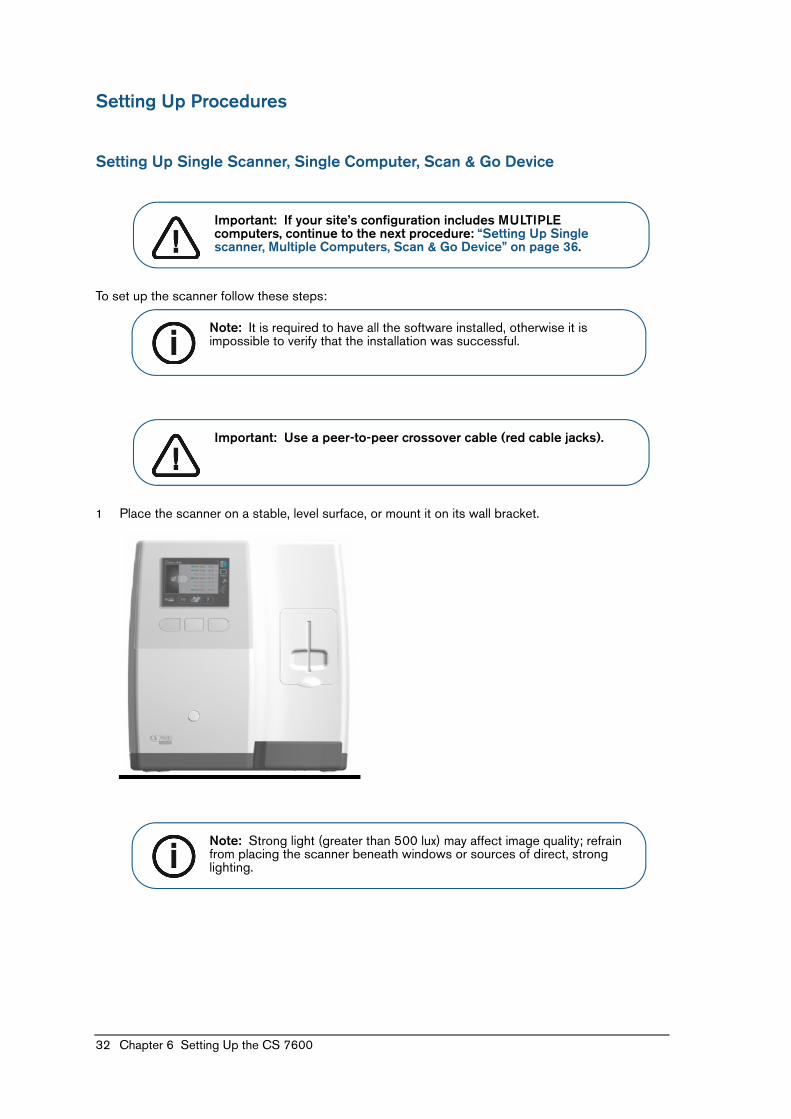
1 Place the scanner on a stable, level surface, or mount it on its wall bracket.
Important: If your site’s configuration includes MULTIPLE computers, continue to the next procedure: “Setting Up Single scanner, Multiple Computers, Scan & Go Device” on page 36.
Note: It is required to have all the software installed, otherwise it is impossible to verify that the installation was successful.
Important: Use a peer-to-peer crossover cable (red cable jacks).
Note: Strong light (greater than 500 lux) may affect image quality; refrain from placing the scanner beneath windows or sources of direct, strong lighting.
32 Chapter 6 Setting Up the CS 7600

2 Remove the cables compartment cover (A) at the back of the system, and connect the assembled power supply’s cable to the scanner’s mains outlet (B) and to a mains wall socket (C).
3 Connect the Ethernet crossover cable (red cable jacks) to the scanner’s Ethernet port (A, B), and to the computer’s RJ-45 port (A, B).
4 (Optional) Connect the USB cable of the Scan & Go device to the computer. See “Scan & Go Device Setup” on page 51.
5 Make sure the computer is turned on and the crossover cable is connected.
A
B
C
B
A
B
ETHERNET
A
CS 7600_Installation Guide (8J6395)_Ed01 33

6 Access the Acquisition interface. (Refer to the Getting Started chapter in the CS 7600 User Guide).
7 Turn on the scanner.
The LCD displays the initializing screens, which include the scanner’s default IP address.
Check that the Insert Plate screen displays the room name in its list and that the connection
status indicator is blue.
1 sec.
34 Chapter 6 Setting Up the CS 7600

8 Check that the scanner is displayed in the Acquisition interface.
9 Insert an exposed (X-ray) imaging plate into the scanner by positioning the open side of the hygienic sheath in the scanner’s insertion panel slot.
10 Press the middle function button to perform a test scan and make sure the image reaches the Acquisition interface.
11 (Optional) Place an imaging plate on the Scan & Go device recording surface to record the exam acquisition data. An audible beep and two successive blinks of the blue LED indicate the exam acquisition information was recorded. Additionally, the Acquisition interface marks the corresponding frame as recorded (frame color changes to indicate recorded status). Perform a test scan of the recorded imaging plate (step 9 and step 10 above) and check that the image populates its correct frame in the Acquisition interface.
12 Perform image quality control. See “Image Quality Control” on page 55.
Note: If the Acquisition interface does not detect the scanner, automatic dynamic IP assignment may be disabled (see page 47). If you need to set a manual IP, refer to page 40.
CS 7600_Installation Guide (8J6395)_Ed01 35

Setting Up Single scanner, Multiple Computers, Scan & Go Device
To set up the scanner follow these steps:
1 Place the scanner on a stable, level surface, or mount it on its wall bracket.
Note: It is required to have all the software installed, otherwise it is impossible to verify that the installation was successful.
Note: Strong light (greater than 500 lux) may affect image quality; refrain from placing the scanner beneath windows or sources of direct, strong lighting.
36 Chapter 6 Setting Up the CS 7600

2 Remove the cables compartment cover (A) at the back of the system and connect the assembled power supply’s cable to the scanner’s mains outlet (B) and to a mains wall socket (C).
3 Connect the standard Ethernet cable (A) to the scanner’s Ethernet port, and to the RJ-45 terminal/wall socket (C). Make sure the room’s computer (B) is connected to the same LAN network as the scanner.
4 Access the CS 7600 Acquisition interface as detailed in the Getting Started chapter in the CS 7600 User Guide. Launch the Acquisition interface at each workstation.
5 Optional: Connect the Scan & Go device USB cable to the computer. See “Scan & Go Device Setup” on page 51. Do this for each workstation.
A
B
C
B
B
ETHERNET
ETHERNET
C
A
AETHERNET
ETHERNET
BB
C
C
CS 7600_Installation Guide (8J6395)_Ed01 37

6 Turn on the scanner.
The LCD displays the initializing screens, which include the scanner’s IP address.
Check that the Insert Plate screen displays the room name in its list and that the network
connection status indicator is blue.
1 sec.1
38 Chapter 6 Setting Up the CS 7600
7 Check that the scanner is displayed in the Acquisition interface.
8 Insert an exposed (X-ray) imaging plate into the scanner by positioning the open side of the hygienic sheath in the scanner’s insertion panel slot.
9 Press the middle function button to perform a test scan and make sure the image reaches the Acquisition interface.
10 (Optional) Place an imaging plate on the Scan & Go device recording surface to record the exam acquisition data. An audible beep and two successive blinks of the blue LED indicate the exam acquisition information was recorded. Additionally, the Acquisition interface marks the corresponding frame as recorded (frame color changes to indicate recorded status). Perform a test scan of the recorded imaging plate (step 8 and step 9 above) and check that the image populates its correct frame in the Acquisition interface. Do this for each workstation that uses a Scan & Go device.
11 Perform image quality control. See “Image Quality Control” on page 55.
Note: If the Acquisition interface does not detect the scanner, automatic dynamic IP assignment may be disabled (see page 47). If you need to set a manual IP, refer to page 40.
CS 7600_Installation Guide (8J6395)_Ed01 39

Setting Up Network Connections, Windows XP
In case your network requires configuring IP addresses manually, follow these steps:
1 Click start > Settings > Network Connections.
2 In the LAN or High-Speed Internet area, right-click the Local Area Connection icon and select Properties.
3 The Local Area Connection Properties dialog box is displayed. Select Internet Protocol (TCP/IP) and click Properties.
Note: This procedure is for computers installed with a Windows XP operating system and when the scanner is connected to the computer via a crossover cable.
40 Chapter 6 Setting Up the CS 7600

4 The Internet Protocol (TCP/IP Properties dialog box is displayed. Select Use the following IP address. To enable communication between the computer and the scanner, both should use the same network identifier in their IP address. See also “Scanner Manual IP Setup” on page 47.
Click OK after entering the IP settings.
5 The Local Area Connection Properties dialog is displayed. click Close and exit Network Connections.
Important: Make sure the IP address entered here uses the same network identifier as the scanner, consult with your network administrator for the appropriate IP settings.
CS 7600_Installation Guide (8J6395)_Ed01 41

6 Start the CS 7600 Acquisition interface and check that the scanner is displayed within 20 s with a green frame in the scanner area.
If the scanner is not displayed with a green frame, refer to the CS 7600 User Guide’s
Troubleshooting chapter.
42 Chapter 6 Setting Up the CS 7600

Setting Up Network Connections, Windows 7
In case your network requires configuring IP addresses manually, follow these steps:
1 Click Start > Control Panel > Network and Sharing Center.
2 In the Network and Sharing Center window, click Local Area Connections.
Note: This procedure is for computers installed with a Windows 7 operating system and when the scanner is connected to the computer via a crossover cable.
CS 7600_Installation Guide (8J6395)_Ed01 43
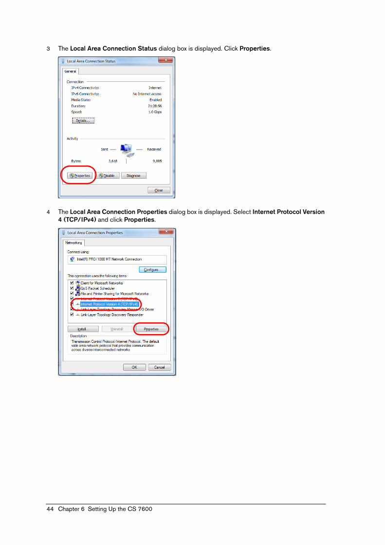
3 The Local Area Connection Status dialog box is displayed. Click Properties.
4 The Local Area Connection Properties dialog box is displayed. Select Internet Protocol Version 4 (TCP/IPv4) and click Properties.
44 Chapter 6 Setting Up the CS 7600

5 The Internet Protocol Version 4 (TCP/IPv4) Properties dialog box is displayed. Select Use the following IP address. To enable communication between the computer and the scanner, both should use the same network identifier in their IP address. See also “Scanner Manual IP Setup” on page 47.
Click OK after entering the IP settings.
6 The Local Area Connection Properties dialog box is displayed. Click Close.
Important: Make sure the IP address entered here uses the same network identifier as the scanner, consult with your network administrator for the appropriate IP settings.
CS 7600_Installation Guide (8J6395)_Ed01 45

7 The Local Area Connection Status dialog box is displayed. Click Close and exit Network and Sharing Center.
8 Start the CS 7600 Acquisition interface and check that the scanner is displayed within 20 s with a green frame in the scanner area.
9 If the scanner is not displayed with a green frame, refer to the CS 7600 User Guide’s Troubleshooting chapter.
46 Chapter 6 Setting Up the CS 7600

Scanner Manual IP Setup
To manually set the scanner’s IP address, follow these steps:
1 Press the scanner’s left function button to access the Settings menu.
2 The Settings screen is displayed. Press the scanner’s left function button to scroll down to IP Setup and press the scanner’s middle function button to apply ( ) your selection.
3 The IP Setup screen is displayed. Use the scanner function buttons to clear the DHCP check box and continue to the IP Address field:
• Use the scanner function buttons to reach the digit you need to change.
• When the digit is framed in blue, press the middle function button to change it to an active orange color.
• Use the function buttons to change the digit’s value.
• Press the middle function button to apply the change: orange digit reverts to default color with blue frame.
• Navigate to the next digit you need to change and change it according to the above instructions.
CS 7600_Installation Guide (8J6395)_Ed01 47

• To apply all changes and exit the IP setup screen, use the function buttons to reach the
confirm button ( ) and then press the middle function button.
• To exit the IP Setup screen without saving changes, use the function buttons to reach the discard button (X) and then press the middle function button.
48 Chapter 6 Setting Up the CS 7600

Scanner SetupTo set up the scanner, follow these steps:
1 From the Insert Plate screen, press the scanner’s right function button.
2 The scanner’s IP address and Scanner Name is displayed. Note this information.
3 Enter this scanner’s IP address in your Internet browser’s address field and press Enter.
4 In the CS 7600 Web page click Setup.
5 Make sure the ScannerName field (A) is populated with the correct scanner name, as you noted in step 2 above.
A
B
D
E
C
CS 7600_Installation Guide (8J6395)_Ed01 49

6 To change the scanner’s interface language from the default of English, select the language from the Language list (B). Click Set (C) to apply these settings.
7 To change the scanner’s date and time, select the correct date and time settings from the Day, Month, Year, Hour, Minutes lists (D). Click Set (E) to apply these settings.
50 Chapter 6 Setting Up the CS 7600

Scan & Go Device SetupTo set up the Scan & Go device, follow these steps:
1 Make sure the computer and scanner are turned on.
2 Connect the Scan & Go device to the computer using its USB cable (A, B).
For multiple computer configurations, do this for each workstation.
AB
ETHERNET
ETHERNET
USBUSB
Note: When using USB cable connection, power is drawn from the connected computer and the Scan & Go device battery is charged.
USB
USB
USB
ETHERNET
ETHERNET
A
A
A
B
B
B
ETHERNET
ETHERNET
CS 7600_Installation Guide (8J6395)_Ed01 51

3 The Found New Hardware message is displayed briefly.
4 The Scan & Go device’s amber charging LED lights up.
5 Access the Acquisition interface. (Refer to the Getting Started chapter in the CS 7600 User Guide.)
6 Place an imaging plate on the Scan & Go device recording surface to record the exam acquisition data. An audible beep and two successive blinks of the blue LED indicate the exam acquisition information was recorded. Additionally, the Acquisition interface marks the corresponding frame as recorded (frame color changes to indicate recorded status).
If this imaging plate is used for testing additional computers, make sure the imaging plate is
recorded by briefly placing it on the Scan & Go device recording surface and verifying that the
overwrite prompt is displayed.
Remove the imaging plate from the Scan & Go device without clicking any option in the prompt
window.
7 Insert the recorded imaging plate into the scanner’s insertion panel slot.
8 Make sure the scanner immediately scans the imaging plate without any prompts on the LCD.
9 Check that the scanned imaging plate image populates the correct frame.
52 Chapter 6 Setting Up the CS 7600

Imaging Processing AdjustmentTo configure the optimal imaging processing filter and preset combination for the workstation, follow these steps:
1 Start the CS 7600 Acquisition interface (refer to the Getting Started chapter in the CS 7600 User
Guide) and click to access the General settings tab.
2 In the imaging processing area click Adjustment mode and then click OK.
3 The main screen is displayed in imaging processing adjustment mode. Scan an exposed imaging plate according to the procedure in the CS 7600 user guide.
4 The scanned image is processed automatically in adjustment mode and the Acquisition interface displays all the preset-filter combinations for each filter. Examine the results and note for each filter its optimal preset.
5 Return to the General settings tab and enter these optimal settings in the image processing area fields.
6 Click OK.
7 Exit the Acquisition interface. (The next time the Acquisition interface is run, it will be in its regular mode.)
CS 7600_Installation Guide (8J6395)_Ed01 53

Configuring the DICOM Character Set EncodingTo ensure the information is rendered correctly on DICOM viewers, regardless of the locale, set the applicable DICOM character set encoding for the site.
To set the applicable DICOM character set encoding for the site follow these steps:
1 Access the CS 7600 Acquisition interface (refer to the Getting Started chapter in the CS 7600
User Guide) and click to access the General settings tab.
2 In the DICOM Character Set area select the character set encoding for the site.
3 Click OK.
Table 6-1 Supported Character Sets
Character Set Languages
Default English only (no DICOM tag sent)
ISO_IR 100 European Languages
ISO_IR 101 Polish
ISO 2022 IR 6 English only
GB18030 Chinese
ISO 2022 IR 87 Japanese for Kanji, full only Katakana, Hiragana
ISO 2022 IR 13_87 Japanese for Kanji, full and half Katakana, Hiragana
ISO 2022 IR 6 Korean
ISO 2022 IR 149 Korean
ISO_IR 126 Greek
ISO_IR 144 Cyrillic (Russian)
ISO_IR 148 Turkish
ISO_IR 166 Thai
ISO_IR 192 UTF-8 for Thai
54 Chapter 6 Setting Up the CS 7600

Image Quality ControlImage quality control testing is performed to assure the unit issues quality images.
Required Tools
• CS 7600 installed with all required software
• Intraoral size 2 imaging plate
• QC tool with step-wedge phantom (not provided with system, order separately)
Pre-requisites
• Clean the imaging plate.
• Verify the imaging plate is not damaged.
• Verify the imaging plate is erased.
Image Quality Control Procedure
To perform the image quality test, follow these steps:
Defining the X-ray and CS 7600 Acquisition interface Settings
1 Set the your clinic’s X-ray generator to the following settings:
2 Start the CS 7600 Acquisition interface (refer to the Getting Started chapter in the CS 7600 User Guide) and click to access the General settings tab.
Table 6-2 Quality testing X-ray parameters
X-ray Tube SID Exposure Duration
70 kVp, 7 mA 12 in. 0.1 s
CS 7600_Installation Guide (8J6395)_Ed01 55

Preparing the QC tool
1 Take out the step-wedge phantom from its housing in the QC tool’s side (A), and insert it into the QC tool’s phantom step-wedge’s groove, until it is clasped by the holders (B).
2 Insert the intraoral imaging plate, without an hygienic sheath, in the QC tool’s imaging plate slot, beneath the aluminum.
3 Place the QC tool on a stable surface.
B
A
56 Chapter 6 Setting Up the CS 7600
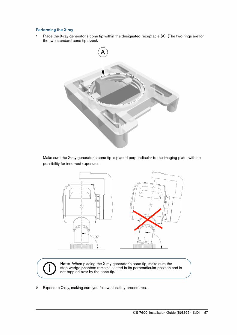
Performing the X-ray
1 Place the X-ray generator’s cone tip within the designated receptacle (A). (The two rings are for the two standard cone tip sizes).
Make sure the X-ray generator’s cone tip is placed perpendicular to the imaging plate, with no
possibility for incorrect exposure.
2 Expose to X-ray, making sure you follow all safety procedures.
A
90°
Note: When placing the X-ray generator’s cone tip, make sure the step-wedge phantom remains seated in its perpendicular position and is not toppled over by the cone tip.
CS 7600_Installation Guide (8J6395)_Ed01 57

3 Remove the cone and extract the imaging plate making sure the imaging plate is minimally exposed to room light.
Scanning the Imaging Plate
1 In the Acquisition interface create a new exam acquisition.
2 Insert the exposed imaging plate into the CS 7600 insertion panel slot. Select the exam acquisition you created in step 1. The imaging plate is scanned and ejected, the image is routed to the CS 7600 Acquisition interface. Collect the imaging plate.
3 Evaluate the image as described in the following section.
Evaluating Image Quality
1 In the CS 7600 Acquisition interface use the Contrast and Brightness options to optimize the image’s visibility.
2 Verify that the following image quality requirements are met:
• The step-wedge phantom’s 6 steps are visible and clearly defined.
• The image is uniform without any artifacts.
• The imaging plate’s 4 rounded corners are visible.
3 If the image quality requirements are not met, apply the following corrective actions.
• The step-wedge phantom’s 6 steps are not visible or clearly defined:
• Adjust the brightness/contrast of the image.
• Verify the X-ray setup.
• The image is not uniform:
• Verify the imaging plate is not damaged.
• Clean the imaging plate.
• The imaging plate’s 4 rounded corners are not visible:
• Eject the imaging plate and reload it.
• Replace the imaging plate.
If all the above does not resolve the image quality issue(s), perform system calibration as detailed
in the CS 7600 Service Guide.
58 Chapter 6 Setting Up the CS 7600