Embed Size (px)
Citation preview
8960 Operation, Verification and
Troubleshooting Guide
E5515 Verification Guide.doc RevE2-4.26.2004 1Page
Contents
Section
Page
1. Purpose
2
2. Troubleshooting Test System Element
3
3. System Problem Resolution Flowchart
4
4. Spare Parts Philosophy
5
5. Activity Timelines
5
6. Operation, Verification and Troubleshooting Guide
Process Efficiency Recommendations
6
Verification Test Record Sheet
7
Verification Test Setup Procedures Test 1 - Power up Self-Test 8 Test 2 - Digital Average Power Calibration 9 Test 3 - Channel Power Calibration 10 Test 4 - RFIO Self-Test 11 Test 5 - I/Q Mod Calibration 12 Test 6 - MDC Test 13 Test 7 - RF Loopback Test 14 Test 8-9 - Call Processing and Measurements 15-16 Test 10 - Boot-up Failure Table 17
7. Appendix Calibration Interval Table 18 Block Diagram and Assembly Description 19-22 Error Messages 23-24 Test Set Verification System Equipment List 25-26 Hard Drive Recovery Procedure 27 8960 Serial Port Logging Procedure 28
Purpose The purpose of this document is to help maintenance personnel quickly assess and debug the performance of integrated Cellular Phone Test Systems developed by Agilent Technologies. This document provides procedures to verify the functional performance of the Test Set while racked in a Test System or on a bench. Although various levels of testing are possible, this document utilizes tests that do not require external test equipment. Available tests include:
User-initiated calibration and verification tests Loopback Self-Tests Mobile phone call processing tests
If located in a racked system, Test Set removal should be avoided after completion of functional performance tests as system level calibration may be compromised. Performing and passing all tests will result in a very high level of confidence that the Test Set is functioning properly. This document is not intended to provide instruction for hardware replacement and repair. If self-maintenance capability is desired contact your Agilent Field Engineer for 8960 Service and Repair certified training details. Desired results from using this document
To quickly isolate cause of Test System problems when related to the Test Set To minimize unnecessary Test Set swapping To identify the root cause of poor Test System yields if related to the Test Set To improve user confidence level in the Test System To educate technicians on Test Set usage
E5515 Verification Guide.doc RevE2-4.26.2004 2Page
To document: - Calibration cycle requirements - Spare instrument and parts requirements - Repair turn around time cycles
Troubleshooting Test System Elements The flowchart in Figure-1 shows the recommended approach to quickly troubleshoot a suspected problem with a Test System and the 8960 Test Set. The time to assess and repair a Test System can range from just a few minutes (replacing or tightening a RF cable) to days (for intermittent problems). A typical Test System repair time is about 1 hour. Check the Test System Cabling Visually inspect the Test System cabling, particularly the cabling to and from the Agilent 8960 and the device under test. Tighten, Replace, or Repair any Test System Cabling if Suspected to be Faulty Tighten, replace, or repair the Test System cabling if it appears to be faulty. The Test System should be re-calibrated if faulty cabling has been detected, particularly any RF cabling. Monitor the performance of the Test System to determine if the problem has been solved. Check the 8960 Performance Execute the 8960 Performance Verification Tests as defined in the Test Description section. The test plan requires about 45 minutes to complete. Upon any failure the following steps should be performed:
Replace the 8960 Check that the replacement Test Set firmware revision is compatible Re-Calibrate the Test System Monitor the performance of the Test System to assure that the problem has been
corrected Repair or ship the Test Set to an Agilent Service Center
Tips on troubleshooting intermittent problems Test Set failures occurring in a Test System may not be repeatable on the repair bench. This type of fault is likely caused by elevated temperatures found in a Test System and is difficult to duplicate. One method to elevate the internal temperature of a Test Set on the bench is to temporarily restrict in/out airflow. Looking from the front of the Test Set, ambient temperature air enters from the right hand side and exits the left at a temperature rise nominally 5-6 degrees centigrade. The following steps should be performed:
Requires two sheets of standard 8 x 11 paper Place sheets flat against the external cover on the right hand side Depending upon the failure symptom, perform the appropriate verification test
E5515 Verification Guide.doc RevE2-4.26.2004 3Page
Recommendation is to perform the quick test suite: Tests 4, 6, and 7

System problem-resolution flowchart Figure-1
E5515 Verification Guide.doc RevE2-4.26.2004
Monitor System performance
A production line problem is reported
Bad connection or defective cable found?
Check System cabling
Run the 8960 Verification quick suite: Tests 4, 6, and 7
Was a fault detected?
- Tighten, replace, or repair cabling
o
o
Run remaining 8960 Verification tests
Was a fault detected?
Yes
test
- Re-calibrate the test system
- Replace the 8960
YesN
- Check for current firmware revision
N
Yes
No
4Page
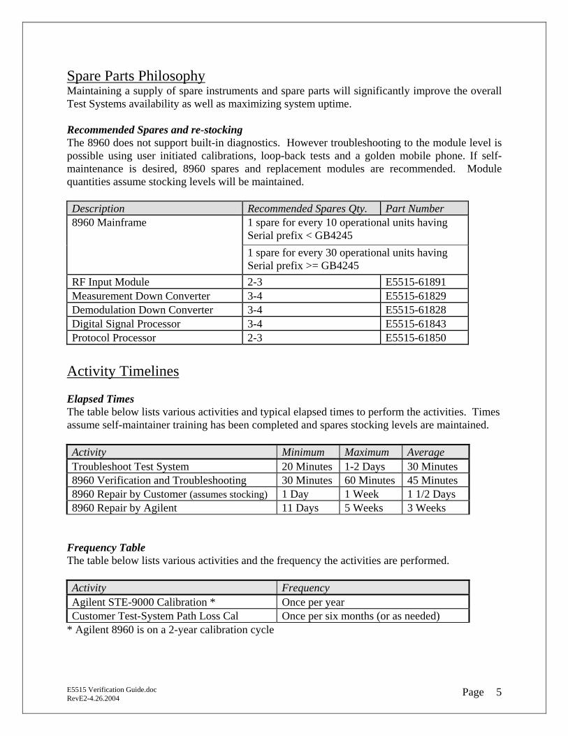
Spare Parts Philosophy Maintaining a supply of spare instruments and spare parts will significantly improve the overall Test Systems availability as well as maximizing system uptime. Recommended Spares and re-stocking The 8960 does not support built-in diagnostics. However troubleshooting to the module level is possible using user initiated calibrations, loop-back tests and a golden mobile phone. If self-maintenance is desired, 8960 spares and replacement modules are recommended. Module quantities assume stocking levels will be maintained. Description Recommended Spares Qty. Part Number
1 spare for every 10 operational units having Serial prefix < GB4245
8960 Mainframe
1 spare for every 30 operational units having Serial prefix >= GB4245
RF Input Module 2-3 E5515-61891 Measurement Down Converter 3-4 E5515-61829 Demodulation Down Converter 3-4 E5515-61828 Digital Signal Processor 3-4 E5515-61843 Protocol Processor 2-3 E5515-61850
Activity Timelines Elapsed Times The table below lists various activities and typical elapsed times to perform the activities. Times assume self-maintainer training has been completed and spares stocking levels are maintained. Activity Minimum Maximum Average Troubleshoot Test System 20 Minutes 1-2 Days 30 Minutes 8960 Verification and Troubleshooting 30 Minutes 60 Minutes 45 Minutes 8960 Repair by Customer (assumes stocking) 1 Day 1 Week 1 1/2 Days 8960 Repair by Agilent 11 Days 5 Weeks 3 Weeks
Frequency Table The table below lists various activities and the frequency the activities are performed. Activity Frequency Agilent STE-9000 Calibration * Once per year Customer Test-System Path Loss Cal Once per six months (or as needed)
E5515 Verification Guide.doc RevE2-4.26.2004 5Page
* Agilent 8960 is on a 2-year calibration cycle
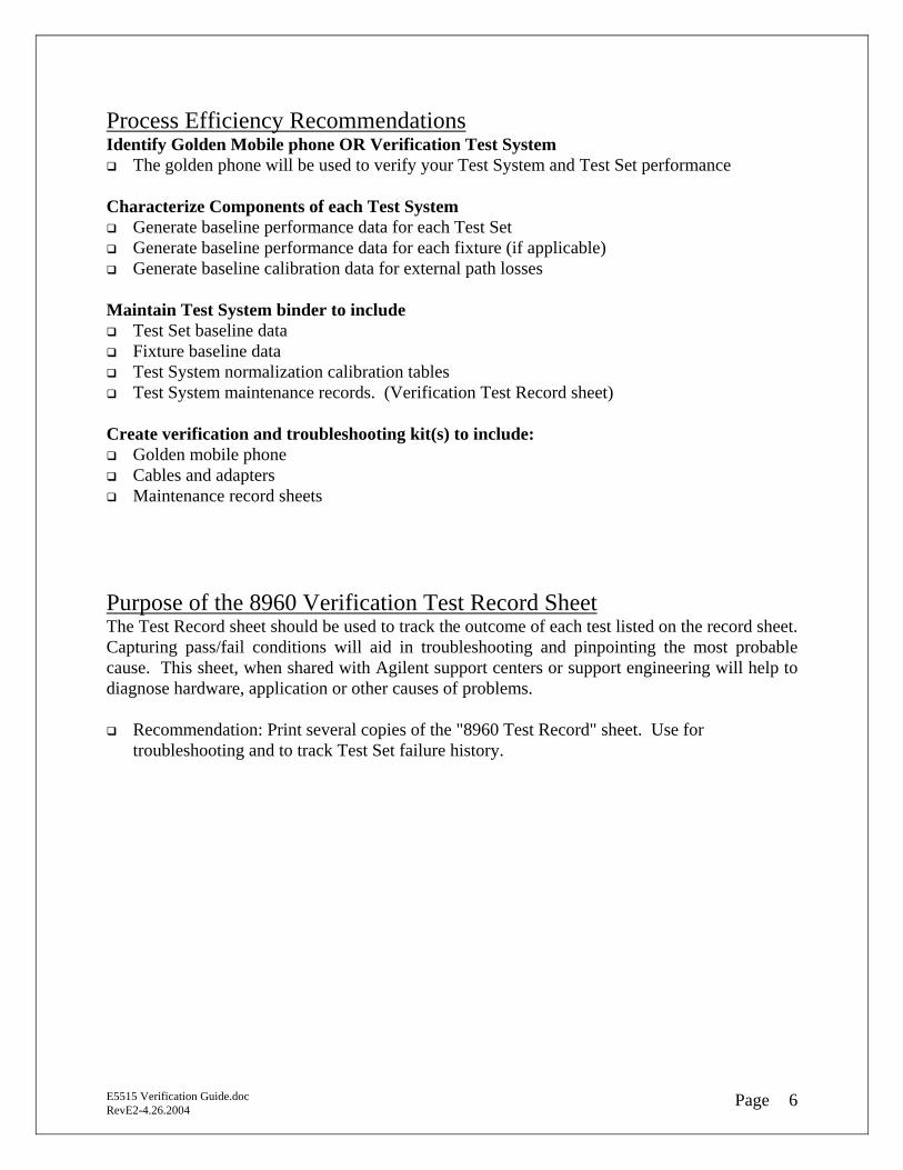
Process Efficiency Recommendations Identify Golden Mobile phone OR Verification Test System
The golden phone will be used to verify your Test System and Test Set performance Characterize Components of each Test System
Generate baseline performance data for each Test Set Generate baseline performance data for each fixture (if applicable) Generate baseline calibration data for external path losses
Maintain Test System binder to include
Test Set baseline data Fixture baseline data Test System normalization calibration tables Test System maintenance records. (Verification Test Record sheet)
Create verification and troubleshooting kit(s) to include:
Golden mobile phone Cables and adapters Maintenance record sheets
Purpose of the 8960 Verification Test Record Sheet The Test Record sheet should be used to track the outcome of each test listed on the record sheet. Capturing pass/fail conditions will aid in troubleshooting and pinpointing the most probable cause. This sheet, when shared with Agilent support centers or support engineering will help to diagnose hardware, application or other causes of problems.
E5515 Verification Guide.doc RevE2-4.26.2004 6Page
Recommendation: Print several copies of the "8960 Test Record" sheet. Use for troubleshooting and to track Test Set failure history.
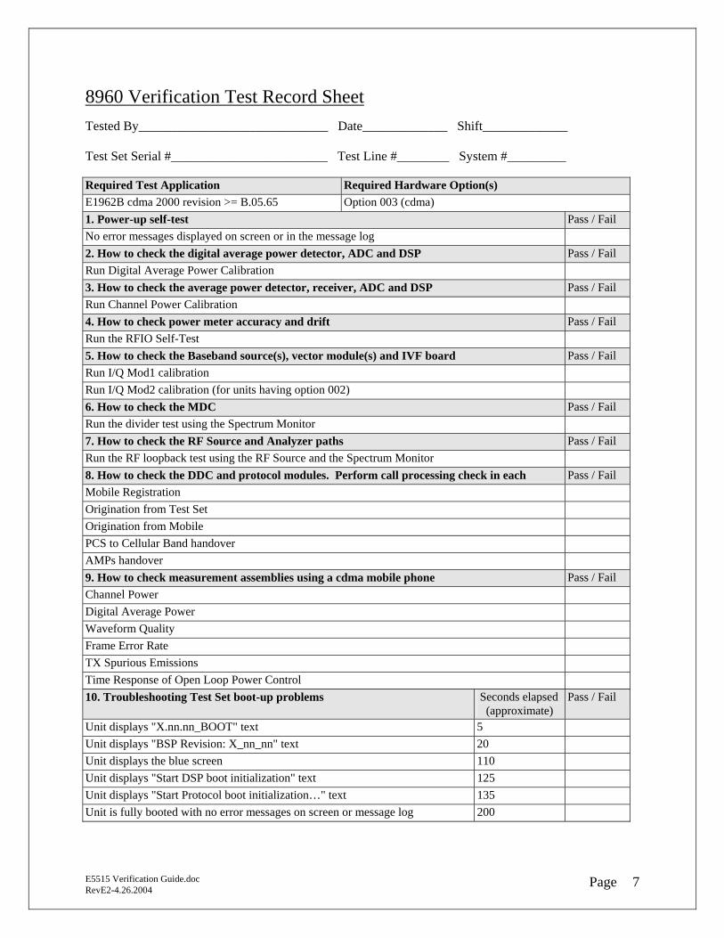
8960 Verification Test Record Sheet Tested By_____________________________ Date_____________ Shift_____________ Test Set Serial #________________________ Test Line #________ System #_________ Required Test Application Required Hardware Option(s) E1962B cdma 2000 revision >= B.05.65 Option 003 (cdma) 1. Power-up self-test Pass / Fail No error messages displayed on screen or in the message log 2. How to check the digital average power detector, ADC and DSP Pass / Fail Run Digital Average Power Calibration 3. How to check the average power detector, receiver, ADC and DSP Pass / Fail Run Channel Power Calibration 4. How to check power meter accuracy and drift Pass / Fail Run the RFIO Self-Test 5. How to check the Baseband source(s), vector module(s) and IVF board Pass / Fail Run I/Q Mod1 calibration Run I/Q Mod2 calibration (for units having option 002) 6. How to check the MDC Pass / Fail Run the divider test using the Spectrum Monitor 7. How to check the RF Source and Analyzer paths Pass / Fail Run the RF loopback test using the RF Source and the Spectrum Monitor 8. How to check the DDC and protocol modules. Perform call processing check in each Pass / Fail Mobile Registration Origination from Test Set Origination from Mobile PCS to Cellular Band handover AMPs handover 9. How to check measurement assemblies using a cdma mobile phone Pass / Fail Channel Power Digital Average Power Waveform Quality Frame Error Rate TX Spurious Emissions Time Response of Open Loop Power Control 10. Troubleshooting Test Set boot-up problems Seconds elapsed
(approximate) Pass / Fail
Unit displays "X.nn.nn_BOOT" text 5 Unit displays "BSP Revision: X_nn_nn" text 20 Unit displays the blue screen 110 Unit displays "Start DSP boot initialization" text 125 Unit displays "Start Protocol boot initialization…" text 135 Unit is fully booted with no error messages on screen or message log 200
E5515 Verification Guide.doc RevE2-4.26.2004 7Page
Test Descriptions and Procedures 1. Power-up Self Test A properly working Test Set will power-up with no messages displayed during and after boot-up. There should be no messages in the Message Log screen. SetupTo access the Message Log screen 1. Press the gray “SYSTEM CONFIG” key 2. Press the F7 key Time to complete Test Set boot-up is approximately 3-4 minutes depending upon the application being loaded Dependency With normal Test Set usage, messages will appear in the Message Log screen. Many messages are NOT error related. If the Test Set is working properly, messages in the message log should be ignored. Action1. See Test Procedure #9 to troubleshoot a boot-up problem
E5515 Verification Guide.doc RevE2-4.26.2004 8Page
2. If error messages are persistent contact your Agilent representative for assistance

2. Digital Average Power Calibration (DAP) This calibration generates calibration data for the Digital Average Power measurement. The RF Source is internally looped in the RFIO module to the thermocouple detector and finally sampled and measured by the ADC and DSP. During calibration the internal temperature of the Test Set will be measured and calibration data will be generated that covers the measurement amplitude range of the available frequency bands The Digital Average Power measurement uses a very accurate thermocouple-measuring device having a dynamic measurement range of +30 dBm to -10 dBm. Executing the Digital Average Power calibration is a quick way to ensure that the power detector, ADC Sampler and DSP are working properly. Setup 1. Press the "Measurement selection" key 2. Use the knob to select the "Digital Average Power" measurement 3. Press the F4 key to execute Digital Average Power calibration Time to complete Approximately 10 minutes Dependency 1. Test Set must be turned on for at least 10 minutes before executing 2. The active application must support cdma 3. No power should be applied to the front panel RF IN/OUT port 4. Test Set power must be cycled after completion. This is necessary to save the calibration results to the
Test Set Hard Disk Drive 5. In normal operation, DAP calibration is executed every 12 months Quick Test - with no RF signal applied 1. Press the "Measurement selection" key 2. Use the knob to select the "Digital Average Power" measurement 3. Check the DAP measured value: - Should read approximately -30 dBm Recommendation
E5515 Verification Guide.doc RevE2-4.26.2004 9Page
1. If the Quick Test fails, check the RFIO

3. Tuned Channel Power Calibration (TCP) This calibration generates calibration data for channel power and access probe power measurements using the accuracy of the fast power detector for cross-calibration accuracy. The RF Source signal is internally looped in the RFIO module to the Receiver path and finally sampled and measured by the Main ADC sampler and DSP. During calibration the internal temperature of the Test Set will be measured and calibration data will be generated that covers the measurement amplitude range of the available frequency bands. The Tuned Channel Power measurement has a dynamic measurement range of +30 to -61 dBm This detector should be chosen for cdma and wcdma power measurements extending below –10 dBm. Channel Power calibration is a quick way to check that the fast power detector, measurement receiver, main ADC sampler and DSP are operating properly. Setup1. Press the "Measurement selection" key 2. Use the knob to select the "Channel Power" measurement 3. Press the F4 key to execute Channel Power calibration Time to complete Approximately 1 minute Dependency 1. Test Set must be turned on for at least 10 minutes before executing 2. The active application must support cdma 3. No power should be applied to the front panel RF IN/OUT port Quick Test - with no RF signal applied 1. Press the "Measurement selection" key 2. Use the knob to select the "Channel Power" measurement 3. Check the Channel Power measured value: - Should read approximately -70 dBm Fail Symptoms 1. Calibration doesn’t complete. May stop or display the red assert screen at 67% or 72% completion.
The most likely cause is a defective MDC module. 2. With no external signal applied, Channel Power measurement value is much higher than -70 dBm Recommendation 2. See Test Procedure #6 to troubleshoot a measurement receiver problem - If the MDC test fails, replace the MDC
E5515 Verification Guide.doc RevE2-4.26.2004 10Page
- If the "no signal applied" quick test fails, check the RFIO
4. RFIO Self-Test The RFIO self-test was designed to identify power amplifier faults in the RF Interface module. Over time the gain of the amplifier(s) may drift resulting in power measurement inaccuracy. The RFIO self-test uses the RF source, a loopback switch in the RFIO, and power detection and measurement assemblies. Setup1. Press the gray “SYSTEM CONFIG” key 2. Press the "More" key located below the F12 key 3. Press the F8 key Time to complete Approximately 10 seconds. Dependency 1. Test Set firmware revision must support the self-test program
- GSM >= A.10.55 - TDMA >= A.07.55 - CDMA >= B.05.65 - WCDMA >= A.01.55
E5515 Verification Guide.doc RevE2-4.26.2004 11Page
2. The RFIO Self-Test baseline must have been activated. If the self-test completes in 1-2 seconds, the RFIO self-test baseline has not been activated. Contact your Agilent representative for assistance.

5. Checking the Vector and Baseband Source Assemblies - I/Q Mod Calibration This calibration generates calibration data for the I/Q Vector Module. The digital data sources are the Baseband Generator(s) for GSM, TDMA and the LSS baseband assemblies for CDMA. Setup1. Press the gray “SYSTEM CONFIG” key 2. Press the "More" key located below the F12 key 3. Press the “Service”, F7 key 4. Select and execute I/Q Mod1 cal 5. Select and execute I/Q Mod2 cal (if unit has option 002) Time to complete Approximately 7-10 minutes per RF Source Dependency A Test Set may have several Test and Lab Applications loaded. Because the I/Q calibration file is used by all applications, it only needs to be executed once. However, because cdma applications require additional cal data for the option 003, Link Subsystem modules, this cal should always be executed in a licensed cdma application. If a cdma application is not available, execute I/Q calibration in any other licensed application.
E5515 Verification Guide.doc RevE2-4.26.2004 12Page
6. Checking the MDC The Measurement Down Converter is the main receiver module providing RF conversion and conditioning for Mobile phone TX measurements. Using the internal Spectrum Monitor feature, it's possible to view the down converted Intermediate Frequency for analysis. Setup 1. Perform a FULL Preset
- Press the blue "SHIFT" key - Press the green "Preset" key
2. Press the "Active Cell”, F1 key - Using the knob, select "CW" operating mode
3. Press the gray "Instrument selection" key located below the display - Using the knob, select "Spectrum Monitor" - Set Frequency Span to: 10 MHz - Set Reference to: -20 dB
4. Press the "RF Gen Freq", F8 key - Enter 293.5 MHz
5. Press the "Receiver Control", F12 key - Using the knob, highlight the "Measurement Frequency" field - Enter 293.5 MHz
6. Perform steps 4 and 5 for the following frequencies: - 854.5 MHz - 1604.5 MHz
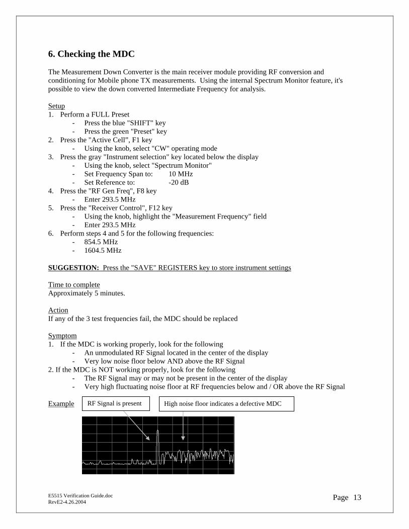
SUGGESTION: Press the "SAVE" REGISTERS key to store instrument settings Time to complete Approximately 5 minutes. Action If any of the 3 test frequencies fail, the MDC should be replaced Symptom1. If the MDC is working properly, look for the following
- An unmodulated RF Signal located in the center of the display - Very low noise floor below AND above the RF Signal
2. If the MDC is NOT working properly, look for the following - The RF Signal may or may not be present in the center of the display - Very high fluctuating noise floor at RF frequencies below and / OR above the RF Signal
Example
E5515 Verification Guide.doc RevE2-4.26.2004 13Page
RF Signal is present High noise floor indicates a defective MDC
7. Checking RF Frequency Accuracy and Level Looping the RF Out Only port to the RF In/Out port allows limited signal analysis with the internal Spectrum Monitor. RF Frequency can be accurately measured over the 292-2700 MHz frequency range of the RF Source, and RF Level can be accurately measured from –15 to –90 dBm. This test assumes the "RF OUT ONLY" port is available, accurate and operating properly. Setup Connect an RF cable between the "RF OUT ONLY" and "RF IN / OUT" ports 1. Perform a FULL Preset
- Press the blue "SHIFT" key - Press the green "Preset" key
2. Make the RF Out Only port active - Press the gray “SYSTEM CONFIG” key - Press the “RF Output Port”, F6 key - Using the knob, select “RF Out Only”
3. Press the gray “CALL SETUP” key - Press the "Active Cell”, F1 key - Using the knob, select "CW"
4. Press the gray "Instrument selection" key located below the display - Using the knob, select "Spectrum Monitor" - Set Frequency Span to: 10 MHz - Set Reference to: 0 dBm - Set Cell Power to: -10 dBm - Set RF Gen Freq to: 450 MHz
5. Press the "Receiver Control", F12 key - Set Expected CW Power to: -10 dBm - Set Measurement Frequency to: 450 MHz - Press the "Close Menu", F6 key
6. Use the Marker to measure RF Frequency and RF Level - Press the “Display”, F6 key - Press the “Marker Mode”, F8 key - Using the knob, select “Position” - Press the “Return”, F6 key to return to the Control Parms screen
7. Checking the RF Source and Analyzer - Press the “Cell Power”, F7 key - Using the knob step the “Cell Power” level down in 1 dB steps - View the Marker Amplitude level at the bottom of the Spectrum Monitor screen - RF Level should be within +/- 1 dB of the Cell Power setting (don’t forget to account for loss in the
external cable) 8. Perform steps 4 - 7 for each of the frequencies below. Don't forget to reset the Marker position accordingly:
- 850 MHz; 1800 MHz; 1900 MHz
SUGGESTION: Press the "SAVE" REGISTERS key to store instrument settings Time to complete Approximately 5 minutes. Action If any of the test frequencies fail troubleshoot to the RF Source or RF Analyzer
E5515 Verification Guide.doc RevE2-4.26.2004 14Page

8-9. Checking the DDC and Protocol using a CDMA Mobile Phone Setup1. Connect the Mobile Phone to the Test Set 2. Setup for Call Processing NOTE: Knowledge of the mobile’s ‘System ID’, ‘Cell Band’, and ‘RF Channel’and "Radio Config", capability are essential to call processing. Therefore, the mobile phone functional test may not be successful if this information is not known. Perform a FULL Preset
- Press the blue "SHIFT" key - Press the green "Preset" key
Press the "More" key located below the F6 key Press the "Cell Info" F2 key Press the "Call Parameters" F2 key (If parms are unknown follow suggestions) Enter System ID # (suggest ID #1) Press the "CALL SETUP" key System Type: Select IS-2000 or appropriate System Type (suggest IS-2000) Cell Power: -55 dBm Cell Band: Use default or select appropriate Band (suggest default) Channel: Use default or enter appropriate Channel (suggest default value) Radio Config Select appropriate Radio Config (suggest Fwd3, Rvs3) FCH Service Option: Select appropriate Service Optio (suggest Fwd3,Rvs3 / SO2) SUGGESTION: Press the "SAVE" REGISTERS key to store instrument settings 3. Turn Mobile Phone ON. Mobile should obtain service with the Test Set
* If capable, the mobile will power-on register in approximately 30-35 seconds indicated by Mobile Station information displayed on the "Mobile Station Information" screen
* The Mobile RSSI indicator should show 4-5 bars 4. Page Mobile Phone Press the "Originate Call" F3 key * Test Set should page the mobile * Mobile should automatically connect to Test Set if loopback option is set * Test Set ‘Connected’ message is at bottom of screen 5. Perform an In-band channel and band to band handoff (mobile should be Dual Band/Mode capable) Press the "Handoff Setup" F5 key * Highlight "Handoff Cell Band" Select appropriate band * Press the "Execute Handoff" F5 key Mobile should not drop call Mobile is operating on the Handoff band * Highlight "Handoff Channel" Enter channel number * Press the "Execute Handoff" F5 key Mobile should not drop call Mobile is operating on the Handoff channel
E5515 Verification Guide.doc RevE2-4.26.2004 15Page
* Press the "End Call" F3 key "Idle" message is at bottom of display
CDMA Mobile Phone Functional Test Continued . . . 6. Originate a call from the Mobile phone (May not work when the Service Option is loopback mode) Dial '123' on the Mobile then press 'YES' or ‘Send’ * Test Set ‘Connected’ message is at bottom of screen * Mobile should be connected in the chosen Service Option state 7. Mobile Phone Measurements Channel Power Test Press the gray "Measurement selection" key * Select the measurement * Measured value should be +/- 1.0 dB of the ‘Expected Mobile Power’ value Digital Average Power Test Press the gray "Measurement selection" key * Select the measurement * Measured value should be +/- .32 dB of the "Expected Mobile Power" value (Cellular band) * Measured value should be +/- .42 dB of the "Expected Mobile Power" value (PCS band) Waveform Quality + Code Domain Test Press the gray "Measurement selection" key * Select the measurement
* Rho should be > 0.95. Typical = .99 Frame Error Rate Test (requires mobile be in a loopback test mode) Press the gray "Measurement selection" key * Select the measurement * Set AWGN Power to – 57 dBm * Test should display "Pass" Time Response of Open Loop Power Control Test (requires mobile be in a loopback test mode) Press the gray "Measurement selection" key * Select the measurement * Press the F2 key - Test should display "Pass" * Press the F3 key - Test should display "Pass" 8. End Call Press the gray "Call Setup" key
E5515 Verification Guide.doc RevE2-4.26.2004 16Page
Press the "End Call" F3 key

10. Boot-up Failure Table Troubleshooting 8960 Boot-up Problems
Symptom Probable Cause(s) Procedure to use (see list below this table
Equipment / Application Required
- Defective Hard Disk Drive 1 (do not replace the HDD) 2
- Defective Host Controller 3
Test Set stops at “Bootrom revision: “
- Corrupt file on Hard Disk Drive
1 OR 2
- PC with LAN card - Crossover cable 8121-0510 - Serial Cable E5515-61215 - 8960 File Utility
Unit display stops at “BSP revision:”
- Corrupt file on Hard Disk Drive
OR - Active TA doesn’t support
the Host Controller or Protocol Processor
1 OR 2 - PC with LAN card - Crossover cable 8121-0510 - Serial Cable E5515-61215
Unit display stops at “DSP Subsystem”
- DSP OR ADC 3 - Serial Cable E5515-61215
Unit displays incorrect Serial Number or “License not found”
Occurs when multiple modules are changed simultaneously
2 AND 4 - PC with serial port - Serial cable E5515-61215 - GPIB cable - GPIB Program
Unit won’t boot after changing the IP address
The first three IP group numbers used by the Host Controller and Protocol Processor IP addresses do not match
5
- PC with serial port - Serial Cable E5515-61215
Unit displays a TA error message
- Wrong license or - Missing license or - Corrupt license
1 AND 2 - PC with LAN card - Crossover cable 8121-0510
Unit continually reboots by itself
- Defective Protocol Processor
- TA BSP file doesn’t support hardware
1 AND 3 - PC with LAN card - Crossover cable 8121-0510 - Serial Cable E5515-61215
Procedure 1 and 3 are included in the Appendix Section of this document. Customers must call Agilent Support for assistance with problems requiring procedure 2, 4, or 5. For assistance call the Spokane Support Hotline at, 1 800 827-3848 1. Hard Drive Recovery Procedure 2. Serial License Fix Procedure (Agilent Confidential - Internal use only) 3. 8960 Serial Port Logging Procedure 4. GPIB Procedure (Agilent Confidential - Internal use only)
E5515 Verification Guide.doc RevE2-4.26.2004 17Page
5. VX Works Procedure (Agilent Confidential - Internal use only)
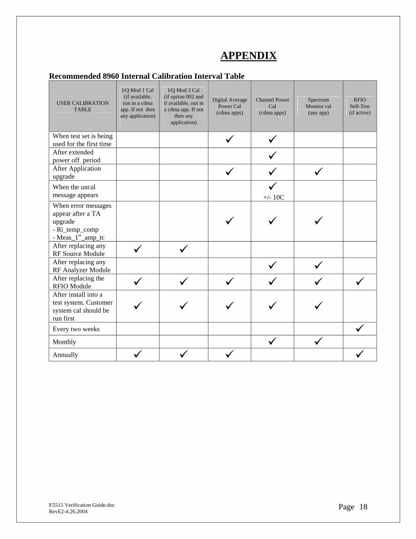
APPENDIX Recommended 8960 Internal Calibration Interval Table
USER CALIBRATION TABLE
I/Q Mod 1 Cal (if available, run in a cdma
app. If not then any application)
I/Q Mod 2 Cal (if option 002 and if available, run in a cdma app. If not
then any application)
Digital Average Power Cal
(cdma apps)
Channel Power Cal
(cdma apps)
Spectrum Monitor cal (any app)
RFIO Self-Test (if active)
When test set is being used for the first time
After extended power off period
After Application upgrade
When the uncal message appears
+/- 10C
When error messages appear after a TA upgrade - Ri_temp_comp - Meas_1st_amp_tc
After replacing any RF Source Module
After replacing any RF Analyzer Module
After replacing the RFIO Module After install into a test system. Customer system cal should be run first
Every two weeks Monthly
Annually
E5515 Verification Guide.doc RevE2-4.26.2004 18Page
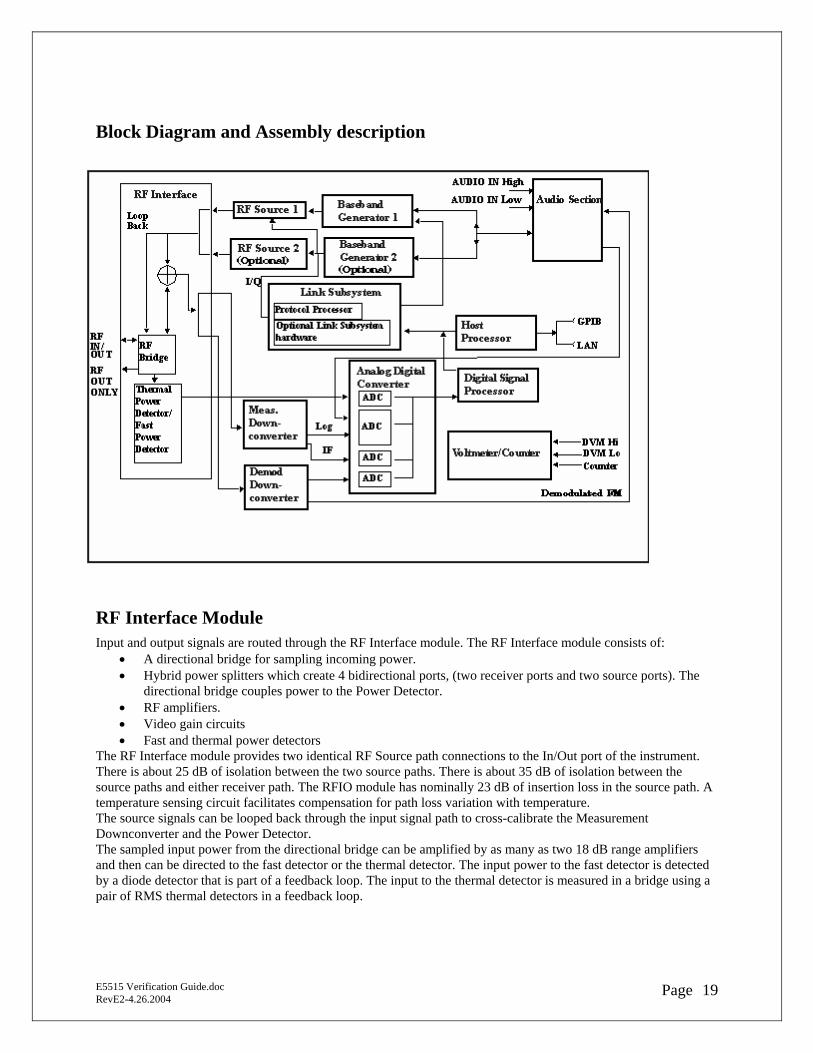
Block Diagram and Assembly description
RF Interface Module Input and output signals are routed through the RF Interface module. The RF Interface module consists of:
• A directional bridge for sampling incoming power. • Hybrid power splitters which create 4 bidirectional ports, (two receiver ports and two source ports). The
directional bridge couples power to the Power Detector. • RF amplifiers. • Video gain circuits • Fast and thermal power detectors
The RF Interface module provides two identical RF Source path connections to the In/Out port of the instrument. There is about 25 dB of isolation between the two source paths. There is about 35 dB of isolation between the source paths and either receiver path. The RFIO module has nominally 23 dB of insertion loss in the source path. A temperature sensing circuit facilitates compensation for path loss variation with temperature. The source signals can be looped back through the input signal path to cross-calibrate the Measurement Downconverter and the Power Detector. The sampled input power from the directional bridge can be amplified by as many as two 18 dB range amplifiers and then can be directed to the fast detector or the thermal detector. The input power to the fast detector is detected by a diode detector that is part of a feedback loop. The input to the thermal detector is measured in a bridge using a pair of RMS thermal detectors in a feedback loop.
E5515 Verification Guide.doc RevE2-4.26.2004 19Page

Signal Downconversion The test set's downconversion receiver section has two downconversion modules; a Measurement Downconversion Module for making measurements, and a Demodulation Downconversion Module for maintaining the radio link.
Demodulation Downconverter Module The Demodulation Downconverter module is used as part of the demodulation receiver that maintains the radio link.
Measurement Downconverter Module The Measurement Downconverter module provides high quality (wide dynamic range, spurious free) signals to the Analog To Digital Converter module's measurement sampler input. The Measurement Downconverter module is designed for very high performance operation to ensure accurate and repeatable measurement results. The Measurement Downconverter module contains two downconversion stages, two local oscillators, and a logarithmic IF envelope detector . Both first and second LO synthesizers are tunable. The first LO is used when tuning to the RF input frequency, and the second LO is used when setting second IF frequency, which is fed to the measurement sampler on the Analog To Digital Converter module.
Link Subsystem The Link Subsystem maintains the radio link for all CDMA formats. The Link Subsystem has two parts:
• Protocol Processor • Optional Link Subsystem hardware
The Protocol Processor module is responsible for maintaining the radio link between the test set and the mobile station under test. The primary tasks of the Protocol Processor module are:
• Generating the protocol messaging necessary for the forward channel and sending that protocol stream to the test set's RF source for transmission to the mobile station
• Decoding the protocol messaging received from the mobile station under test on the reverse channel • Computing measurement results which are associated with data bits contained within the mobile stations
messaging, such as bit error ratio and frame error rate. The optional Link Subsystem hardware provides additional signaling link control for CDMA signaling formats. These include:
• Layer 1 digital signal processing • Providing I/Q baseband signals which are sent to the I/Q modulator in the RF Source
Analog To Digital Converter Module Following the Measurement Downconverter and Demodulation Downconverter IF 1 is the Analog to Digital Converter module. The purpose of the Analog to Digital Converter module is to convert the downconverted analog signals into digital data streams which can be processed by the Digital Signal Processing module. In order to maintain the radio link of non-CDMA formats, the downconversion path through the Demodulation Downconverter module has a dedicated A/D conversion path. To optimize measurement throughput, the fast RF power detector also has a single dedicated A/D path. This allows power measurements, in many cases, to be made concurrently with other measurements. The two outputs from the Measurement Downconverter module and the Audio In signal share a single multiplexed A/D path. The outputs of the various analog to digital converters on the Analog to Digital Converter module share a common data bus with the Digital Signal Processing module.
Digital Signal Processing Module The Digital Signal Processing (DSP) module is responsible for a variety of tasks within the overall test set architecture. These tasks are:
• demodulating data from the radio under test (data received from the Demodulation Downconverter module) and sending the demodulated data bits to the Protocol Processor module
E5515 Verification Guide.doc RevE2-4.26.2004 20Page
• for some systems, perform audio measurements using audio information sent to the DSP module from the Protocol Processor module
• execute a variety of signal processing algorithms to perform measurements on the radio system of the currently loaded TA (data received from the power detector ADC, the measurement ADC and, in some cases, data received from the Demodulation Downconverter ADC)
The DSP processor communicates with the Host Processor and the Protocol Processor, as well as controlling the configuration and synchronization of the Analog To Digital Converter module.
Host Processor Module The Host Processor module is responsible for a variety of tasks within the overall test set architecture. These tasks include:
• control of the manual user interface (MUI) • executing commands and processing data received from the LAN interface • executing commands and processing data received from the GPIB interface • controlling hard disk access • control of all RF and audio hardware modules • routing measurement results received frm the Digital Signal Processing and Protocol Processor modules to
the appropriate output device (display, GPIB, LAN, serial, etc.)
Voltmeter/Counter
Voltmeter The voltmeter is used to measure internal voltages for instrument self-diagnostics.
Frequency Counter The Frequency Counter is used to measure external frequencies from the front panel Audio IN, High or Low BNC connectors, and to measure internal signals for diagnostics. The external input can receive a signal between 20 Hz and 50 MHz, with a level from 25 mV to 8 V rms.
Audio Section
Audio Analysis Path Externally applied audio signals can be analyzed through the test set's DSP module for such characteristics as AC level, SINAD, or distortion. The audio signal to be analyzed is input to the test set using the front panel Audio IN High/Low connectors. The signal is then routed to the Analog To Digital Converter module's measurement sampler for analysis by the DSP module. The Audio In connector accepts signals from 20 Hz to 15 KHz, at input levels from 10 mV to 20 V peak.
Audio 1 Path The Audio 1 path provides analog baseband signals used for frequency modulation of the test set's RF sources. Up to four separate audio sources may be summed together in any combination to provide the composite Audio 1 output. These include the external FM input, internal direct digital synthesis (DDS,) regenerated SAT, and audio echo input. The external FM input accepts an externally supplied audio signal with a peak voltage between 0.25 and 2 V peak. The internal DDS generates low distortion audio signals from DC to 20 KHz with 0.1 Hz resolution. One to four signals may be generated and internally summed, with independent level control of each waveform. The SAT regeneration circuit outputs a signal which is phase-locked to a received SAT signal. This is useful for testing situations where the test set needs to emulate a mobile station. The audio echo input is used for retransmitting the received audio after a selectable time delay, to check both radio transmit and receive paths simultaneously.
E5515 Verification Guide.doc RevE2-4.26.2004 21Page
For most applications, only one or two of these Audio 1 path sources are enabled at any given time.
Audio 2 Path The Audio 2 path provides a secondary means for sending analog baseband signals to the FM modulator. Audio 2 contains only one source, a DDS similar to that used for Audio 1. Typically, the Audio 2 path DDS is used for cases where multiple signals must be summed together with the lowest possible distortion. Another potential use of Audio 2 would be to obtain higher output levels than Audio 1 is capable of (up to twice as much), assuming the two outputs are set to the same frequency and phase, and then summed together at the Baseband Generator module. Audio 2 is rarely used in practice because the DDS used for Audio 2 is the same DDS that is used for the front panel audio output.
Audio Out Path Any one of four inputs may be coupled to the front panel audio output connector. These include a 4 channel DDS (shared with Audio 2), receiver discriminator audio from the Demodulation Downconverter module, audio echo from the Analog To Digital Converter module, and audio vocoder. The front panel output is capable of providing signal levels up to 9 V peak into > 600 ohm loads, and up to 0.8 V peak into an 8 ohm load (e.g. speaker). The output level is calibrated for all modes except discriminator audio, The discriminator audio has an uncalibrated volume control provided due to the high tolerances involved. Typically the DDS mode is used to feed the MIC input of a radio, or it may simply be used as a general purpose low distortion function generator. Audio echo can be selected to route the received audio to the front panel audio output connector.
RF Sources The test set has up to two identical RF sources. The RF sources are used to provide analog or digitally modulated RF carriers for use in parametric testing of mobile stations encompassing a variety of cellular radio formats. In general, the sources have a frequency range of 292 MHz to 2.7 GHz and an amplitude range of -10 dBm to -127 dBm. The RF sources consist of a Synthesized Signal Generator module followed by a Vector Output module and an RF Attenuator module. Baseband modulation information is supplied to the RF sources from a Baseband Generator module preceded by an Audio Section module.
Baseband Generators The purpose of the Baseband Generator module is to provide, for the modulation type currently in effect, properly formatted baseband signals to the modulation circuits on the RF Source modules. The Baseband Generator performs several functions related to the generation and processing of these base-band modulation signals. These are:
• Transform data and clock signals from the Protocol Processor module into base-band analog I/Q modulation signals for the I/Q modulator in the Vector Output module
• Transform data from the Protocol Processor module into baseband FSK modulation for the FM modulator in the Signal Generator module
• Provide baseband FM path source selection, gain adjustment and summing node for analog FM signals from the Audio module and internally generated baseband FSK signals which are output to the FM modulator in the Signal Generator module
E5515 Verification Guide.doc RevE2-4.26.2004 22Page
• Transform burst and adjacent timeslot signals from the Protocol Processor module into baseband burst modulation signals for the burst modulator in the Vector Output module
Error Messages To view less or more verbose error messaging, change the "Message Display Verbose Level" setting: - Press the gray "SYSTEM CONFIG" key - Press the "Instrument Setup", F1 key - Use the knob to scroll and and make your selection Each error message that is generated is recorded in either the error/event queue or the message log or both. Error messages are shown in a message window at the center of the test set's display. When an error message is displayed an audio beep occurs, the beeper state of the test set can be set to on or off. The error/event queue is read remotely using the SYSTem:ERRor? query. The error/event queue is able to hold 100 messages. To read the entire error/event queue use the following program. 10 DIM Err_msg$[255] 20 REPEAT 30 OUTPUT 714;"SYSTEM:ERROR?" 40 ENTER 714; Err_num,Err_msg$ 50 PRINT Err_num,Err_msg$ 60 UNTIL Err_num = 0 The message log may be viewed on the test set's display by pressing the SYSTEM CONFIG screen's Message Log key. The message log can display up to 24 entries over two pages. Error messages can be cleared from the test set's display using the DISPlay:WINDow:ERRor:CLEar command. Pressing any functional front panel key, i.e. the LOCAL key, will clear an error message for the test set's display.
Classes of Errors Error messages are divided into classes, each class of error is handled differently by the test set. The message log is cleared when the test set is power cycled.
Measurement Integrity Indicators These messages occur as a result of a measurement, they indicate the validity of the measurement. Measurement integrity indicators are read with the FETCh command.
Non-Persistent Errors These messages are generated when a condition occurs that is incorrect, but has no serious or long lasting effect on the test set's operation. Examples could include an out of range value to a parameter, or an invalid GPIB mnemonic. The message window is cleared when any front panel key is pressed.
Persistent Errors These errors are generated when a non-transitory error condition exists. Persistent errors occur when a hardware failure is found, or when damage or injury to a person or the test set may occur. The test set displays these errors in the error message window and as a prompt at the bottom of the display screen where it remains until the error condition no longer exists.
Fatal Errors
E5515 Verification Guide.doc RevE2-4.26.2004 23Page
When these errors occur no further operation of the test set is possible without cycling the power switch. Fatal errors are not saved in the error message log. The test set display will provide the user with information about what to do next and some details about what the test set was doing when the fatal error occurred.
Maskable Messages These messages are intended to inform the user of a condition within the test set. They are generally meant to provide information to the user. The user will need to decide if this condition is undesirable and if they want the message to appear. Maskable Message Display State
The Maskable Messages Display State found in the Instrument Setup menu gives users a way to block these messages and the associated beep from ever happening. When the state is Off these messages and their associated beep will be blocked. The Maskable Message Display State can be set manually or with the following GPIB command: OUTPUT 714;"DISPLAY:MESSAGE:MASKABLE:STATE OFF" !Prevents certain messages from appearing on the display.
Instrument Maskable Messages • Instrument warning: Audio Generator instrument has been closed. • Instrument warning: Audio Analyzer instrument has been closed.
E5515 Verification Guide.doc RevE2-4.26.2004 24Page
• Instrument warning: Analog Audio instrument has been closed.

Test Set Verify System Requirements Running Windows® 95, 98, NT4.0, 2000 or XP For the Help system to work, Windows® Internet Explorer version 4 or higher must be installed. Hardware: 5 MB of free hard disk space (or more if you intend on extensive archiving of the test results), 64 MB RAM, 800x600 monitor, GPIB output port with appropriate VISA drivers and a printer is optional. A security key is also needed to run this program: Part Number: 1258-0713 The Test Set Verify Program automates procedures that verify the basic functioning of the Agilent 8960 RF Communication Mobile Test Sets. It requires three instruments:
• RF Communications Mobile Test Set (the unit under test) • ESG-4000D, ESG-D, or ESG-DP Series Signal Generator • E4406 Series VSA Transmitter Tester
Test equipment will need the correct options for the technologie(s) being tested.
E5515 Verification Guide.doc RevE2-4.26.2004 25Page
This is the only equipment that will work with the software. Other instruments, even near equivalents, may not function properly or may not have the measurement accuracy. In addition the personalities of the test instruments must have personalities that match the Test Set being tested
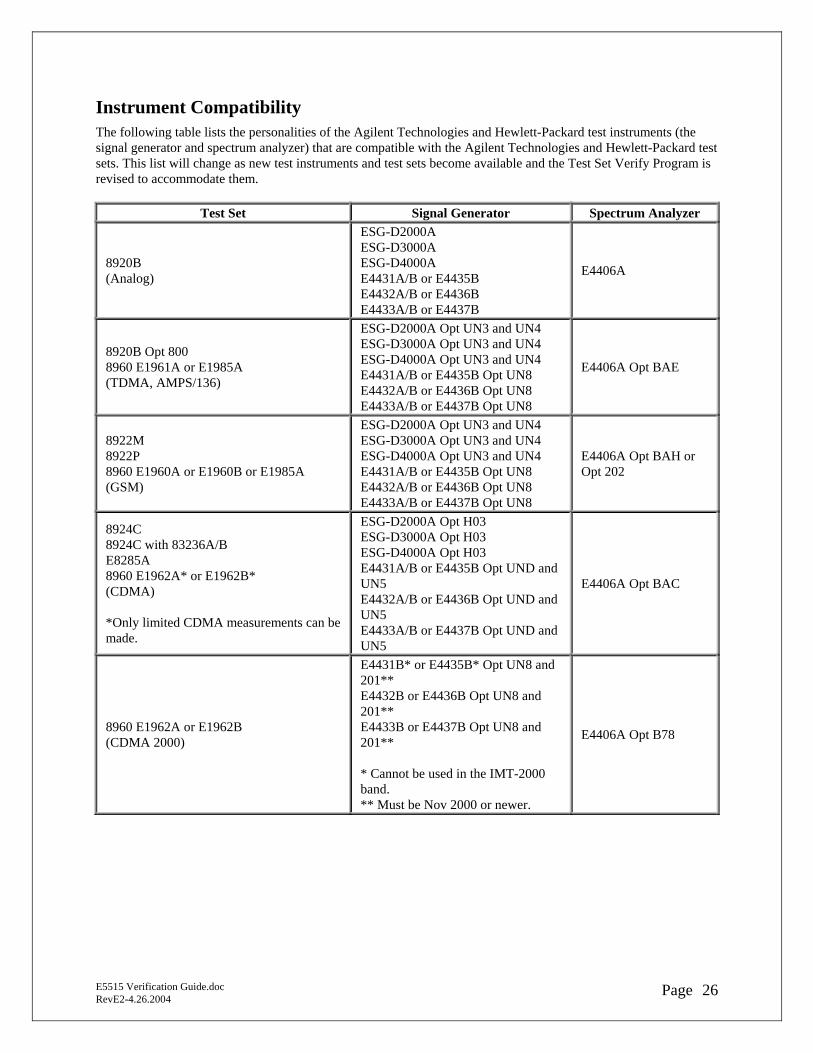
Instrument Compatibility The following table lists the personalities of the Agilent Technologies and Hewlett-Packard test instruments (the signal generator and spectrum analyzer) that are compatible with the Agilent Technologies and Hewlett-Packard test sets. This list will change as new test instruments and test sets become available and the Test Set Verify Program is revised to accommodate them.
Test Set Signal Generator Spectrum Analyzer
8920B (Analog)
ESG-D2000A ESG-D3000A ESG-D4000A E4431A/B or E4435B E4432A/B or E4436B E4433A/B or E4437B
E4406A
8920B Opt 800 8960 E1961A or E1985A (TDMA, AMPS/136)
ESG-D2000A Opt UN3 and UN4 ESG-D3000A Opt UN3 and UN4 ESG-D4000A Opt UN3 and UN4 E4431A/B or E4435B Opt UN8 E4432A/B or E4436B Opt UN8 E4433A/B or E4437B Opt UN8
E4406A Opt BAE
8922M 8922P 8960 E1960A or E1960B or E1985A (GSM)
ESG-D2000A Opt UN3 and UN4 ESG-D3000A Opt UN3 and UN4 ESG-D4000A Opt UN3 and UN4 E4431A/B or E4435B Opt UN8 E4432A/B or E4436B Opt UN8 E4433A/B or E4437B Opt UN8
E4406A Opt BAH or Opt 202
8924C 8924C with 83236A/B E8285A 8960 E1962A* or E1962B* (CDMA) *Only limited CDMA measurements can be made.
ESG-D2000A Opt H03 ESG-D3000A Opt H03 ESG-D4000A Opt H03 E4431A/B or E4435B Opt UND and UN5 E4432A/B or E4436B Opt UND and UN5 E4433A/B or E4437B Opt UND and UN5
E4406A Opt BAC
8960 E1962A or E1962B (CDMA 2000)
E4431B* or E4435B* Opt UN8 and 201** E4432B or E4436B Opt UN8 and 201** E4433B or E4437B Opt UN8 and 201** * Cannot be used in the IMT-2000 band. ** Must be Nov 2000 or newer.
E4406A Opt B78
E5515 Verification Guide.doc RevE2-4.26.2004 26Page
8960 Hard Disk Drive Recovery Procedure The 8960 Test Set is designed to use files located on the hard disk drive to boot up properly, i.e. Operating System, Test Applications, Calibration and License files, and Board Support Packages. For reasons unknown, files may get erased or corrupted and the Test Set is not operational. This procedure uses the 8960 File Utility, LAN and Serial cables to recover from a corrupt or missing file condition. Items required for this procedure - Desktop or Laptop PC configured with a LAN card - LAN crossover cable, 8121-0510 - Serial cable, E5515-61215 - License certificate matching instruments serial number and test application Download Test Application License File For a Test Application to be activated, a valid license file must be found on the unit hard disk drive. If the license.txt file is missing, corrupt, or does not contain a valid license specific to the serial number of the unit, then the valid license file should be downloaded via the web to the unit using the following procedure. If the license file is ok, skip this step. 1. Go to http://www.agilent.com/find/softwarelicense/ 2. Enter the license number, press SUBMIT 3. Select “Previously Generated License Files” 4. Save the license file to directory: C:\Test_Set_Data\Licenses 5. The license will be loaded onto the 8960 during the firmware upgrade procedure Steps to recover from a corrupt file on the Hard Disk Knowing the IP address for the Test Set is not necessary for this procedure as the 8960 File Utility will automatically set the IP address of the Test Set to 1 + the computer IP address 1. Connect the laptop LAN cable to the 8960 LAN port on the front panel. 2. Turn the unit on 3. Start the “Agilent 8960 File Utility” 4. Select “Options” from the Welcome page 5. Select “Power Up Monitoring/ Hard Drive Recovery” 6. Follow the set up diagram:
- Connect the computer LAN cable to the 8960 LAN port on the front panel - Connect the computer COM port, to the 8960 SERIAL 1 port on the rear panel - NOTE: Check that no other application is using this port!
7. When all physical connections are made, select “OK’ 8. Turn the Test Set power off and back on when prompted 9. At this point, the recovery software will take over and if all goes well, the standard application load
screen will be displayed on your computer 10. Highlight desired application and select "Upload To Test Set" 11. The software will upload the selected TA and inform you to cycle power 12. When done, exit from the File Utility program. The Test Set should boot up completely Recommendation
E5515 Verification Guide.doc RevE2-4.26.2004 27Page
You may have to diable Firewall software and IE proxy settings
8960 Serial Port Logging Procedure When to use this procedure If the Test Set is rebooting, or stops during a bootup , logging data from the serial ports will provide important information to aid in troubleshooting a hardware problem. Items required for this procedure - Desktop or Laptop PC with available serial port - RJ-11(m) to DB-9(f) Serial cable, E5515-61215 (Cable must be 6-pin conductor type. The 4 pin, RJ-ll cable will not work) Viewing data - Turn OFF the E5515 - For Control data: Connect the serial cable from the PC to the HOST port (SERIAL1) - For Protocol data: Connect the serial cable from the PC to the PROTOCOL port (SERIAL3) - Start and create a HyperTerminal session using these settings:
• Baud Rate = 38400 • Data Bits = 8 • Parity = None • Stop Bits = 1 • Flow Control = Xon / Xoff
- Turn ON the E5515 Instrument Boot-up information and data should be displayed on your PC screen Capturing data All data that has been logged to the HyperTerminal session can be saved to a *.txt file - On the HyperTerminal Menu, click “Transfer” - Click “Capture Text” - Use the “Browse” button to change to the desired directory and to name the file Interpreting the data Because the logged file is large, a qualified Customer Support Engineer should do interpretation of data. Please email both Host and Protocol log files to [email protected] or call the Spokane Service Hotline at 1 800 827-3848.
E5515 Verification Guide.doc RevE2-4.26.2004 28Page