Embed Size (px)
Citation preview

, ~ 8 9 - 1 8 5 % 5
STUDIES . A N D ANALYSES OF THE
SPACE SHUTTLE M A I N ENGINE
Contract No. NASw-3737
FINAL REPORT
BCD-SSME-TR-87-3
December 31, 1987
A. E. Tischer and R. C. Glover
Prepared For
National Aeronautics and Space Administration George C. Marshall Space Flight Center Marshall Space Flight Center, AL 35812
BATTELLE Columbus Division 505 King Avenue
Columbus, Ohio 43201 -2693
https://ntrs.nasa.gov/search.jsp?R=19890009154 2020-04-17T18:06:13+00:00Z

STUDIES AND ANALYSES OF THE
SPACE SHUTTLE M A I N ENGINE
Contract No. NASw-3737
FINAL REPORT
BCD-SSME-TR-87-3
December 31, 1987
A. E. Tischer and R. C. Glover
Prepared For
National Aeronautics and Space Administration George C. Marshall Space Flight Center Marshall Space Flight Center, AL 35812
A. E. Tischer Manager SSME Study
1 N. H. Fischer Manager Space Systems Section
BATTELLE Columbus Division 505 King Avenue
Columbus, Ohio 43201-2693

This report is a work prepared for the United States by Battelle. In no event shall either the United States or Battelle have any responsibility or liability for any consequences of any use, misuse, inability to use, or reliance upon the information contained herein, .nor does either warrant or otherwise represent in any way the accuracy, adequacy, efficacy, or applicability of the contents hereof.

ABSTRACT
This report documents all of the activities on Contract No.
NASw-3737. This contract was initiated in July 1983 and extended through December 1987. The primary objectives of this study were to: evaluate ways to maximize the information yield from the current Space Shuttle Main Engine (SSME) condition monitoring sensors, identify additional sensors or monitoring capabilities which would significantly improve SSME data, and provide continuing support of the Main Engine Cost/Operations (MECO) model. In the area of SSME condition monitoring, the principal tasks were a review of selected SSME failure data, a general survey of condition monitoring, and an evaluation of the current engine monitoring system. A computerized data base was developed to assist in modeling engine failure information propagations. Each of the above items is discussed in detail in this report. Also included is a brief discussion of the activities conducted in support of the MECO model.

EXECUTIVE SUMMARY
The National Aeronautics and Space Administration (NASA) is currently funding a number of research programs in condition monitoring. The primary goals of these efforts are to increase the safety and reliability of the Space Shuttle and to reduce the cost associated with vehicle turnaround. This study provides an independent assessment of the condition monitoring priorities for the Space Shuttle Main Engine (SSME) and evaluates potential improvements to the present SSME condition monitoring system.
Studv Supports SSME Development and Operation
The objectives of this study, performed from July 1983 through December 1987, were directed at generating results which would support program planning for improved SSME condition monitoring. The study included both flight and ground test operations. Specifically, the study objectives were:
Evaluate ways to maximize the information yield from the current SSME condition monitoring sensors
Identify additional sensors or monitoring capabilities which would significantly improve engine data.
Reviewed SSME Failure Data and Surveved Status of Condition Monitorinq
The review of SSME failure information concentrated on the Unsatisfactory Condition Reports (UCRs) generated and tracked by Rocketdyne from January 1980 through November 1983. This activity included collection and reduction of the UCRs to determine SSME failure modes, categorization of the failure modes, ranking of the failure modes, identification and evaluation of measurable parameters for each failure mode, and identification of parameters for possible trending of engine condition. This review established an understanding of the SSME operating characteristics and failure modes.
The condition monitoring survey included devices and approaches for collecting, processing, and interpreting degradation and/or failure
i
information. The task determined the status of condition monitoring in the areas of liquid rocket engines, aircraft gas turbines, and heavy machine industries (refining, power generation, etc.) . This survey identified new diagnostic sensors, signal processing techniques, and condition monitoring approaches which might be useful for the SSME.
Developed Failure Information Propagation Model Data Base and Modeled SSME Components
A data base and supporting software was developed to store, maintain, and manipulate failure information propagation data for major SSME components. The information generated and entered in this data base is part of a systematic evaluation of failure data available at various test points in the component. The data base can be used to evaluate ways to extract additional condition monitoring information from the current engine sensors. The data base can also be used to analyze potential locations for new sensors.
A complete failure information propagation model (FIPM) was developed for the high-pressure oxidizer turbopump (HPOTP) . The HPOTP FIPM consists of a drawing of the turbopump and a set of data base files containing all of the information generated for this engine component. The HPOTP FIPM consists of 105 modules (piece parts or functions), 198 connections, 260 failure modes, and 8213 failure information propagations.
FIPM drawings were also prepared for the following engine components: high-pressure fuel turbopump, 1 ow-pressure oxidizer turbopump , 1 ow-pressure fuel turbopump, heat exchanger , oxidizer preburner, fuel preburner, main injector, main combustion chamber, and nozzle.
Results and Conclusions Emphasize Continued Development of Specialized SSME Sensors and Techniques
Turbopumps Have Hiqh-Priority for Condition Monitorinq. The review of the SSME failure data included in this study indicated that the engine turbopumps are very high on the list of components to be monitored. A major item of interest in the turbopumps is the condition of the bearings. This review also indicated that there is a distinct division between monitoring for safety and maintenance purposes. This distinction
i i

is the result of the time constants involved in major engine failures. Most failure modes currently cannot be detected early enough to safely shut down the engine. Hydrogen leak detection was also shown to be a major area of concern from the standpoint of engine turnaround and launch processing.
SSME Represents State of the Art in Rocket Enqine Condition Monitorinq. The survey of condition monitoring found no sensors or techniques associated with other rocket engines which would improve the availability of SSME degradatiodfailure information. However, several promising techniques such as gas-path analysis and pattern recognition could provide future improvements in engine monitoring. Improvements in computer processing speed would be required before these approaches could be used in flight. Image processing was identified as a means for improving the quality o f internal visual inspections conducted on SSME components.
Inteqrated Svstem Needed to Track and Analyze SSME Condition Data. A major finding of this study was the need for an integrated system to store, evaluate, and report information related to SSME condition monitoring. This system must include both the flight and ground test operations conducted by NASA and Rocketdyne. 'Once collected, the information must be reviewed and analyzed to identify significant trends or patterns which indicate engine condition. This data tracking system must include historical data on engine operations and performance.
FIPM Useful in Evaluating Enqine Monitorinq Requirements. The FIPM approach was successfully modified to model the flow of information in the SSME components. The data base format allowed a substantial amount of data to be stored and manipulated. The records contained in the data base were used to analyze the failure information detectable by current HPOTP sensors and to evaluate several locations for new monitoring devices . Recommendations Encouraqe Continued Research and Development of SSME Condition Monitorinq System
The recommendations provided below were formulated during the conduct of this study:
i i i

Continue the development and testing of new sensing techniques which target specific SSME failure modes (fi beroptic deflectometer, optical pyrometer, etc .)
Design and develop an integrated condition monitoring system which includes both safety (real-time) and maintenance (off- line or ground-based) elements
Pursue pattern recognition as a means for improving on-board engine condition monitoring
Establish a condition monitoring data base to collect and integrate SSME historical and operational information
Increase the computational capability of the SSME controller to expand engine monitoring
Utilize the oxygen/hydrogen technology test bed engine to test and validate promising condition monitoring improvements.
iv

TABLE OF CONTENTS
Paqe INTRODUCTION . . . . . . . . . . . . . . . . . . . . . . . . . . . . 1
SSME FAILURE DATA REVIEW . . . . . . . . . . . . . . . . . . . . . . 5
F a i l u r e Modes Analys is . . . . . . . . . . . . . . . . . . . . . 5
Data C o l l e c t i o n . . . . . . . . . . . . . . . . . . . . . . . 5 UCRReview . . . . . . . . . . . . . . . . . . . . . . . . 6 SSME Acc ident / Inc ident Reports Review . . . . . . . . . . . 13 F a i l u r e Modes and E f fec ts Analysis Report Review . . . . . 14 Test F i r i n g Cu to f f UCRs Review . . . . . . . . . . . . . . 16 F a i l u r e Mode Ranking . . . . . . . . . . . . . . . . . . . 18
Measurement Parameter Analysis . . . . . . . . . . . . . . . . . 19 Conclusions . . . . . . . . . . . . . . . . . . . . . . . . . . 27 Recommendations . . . . . . . . . . . . . . . . . . . . . . . . 28
P a r t i a l l y Developed and Tested . . . . . . . . . . . . . . 29 Devices w i t h Major Development E f f o r t s Needed . . . . . . . 30
DIAGNOSTICS SURVEY . . . . . . . . . . . . . . . . . . . . . . . . . 33
Survey Approach and Methodology . . . . . . . . . . . . . . . . . 33
Approach . . . . . . . . . . . . . . . . . . . . . . . . . 33 Methodology . . . . . . . . . . . . . . . . . . . . . . . . 34
Diagnost ics Background . . . . . . . . . . . . . . . . . . . . . 35
D e f i n i t i o n s . . . . . . . . . . . . . . . . . . . . . . . . 35 S ta te I d e n t i f i c a t i o n Process Hierarchy . . . . . . . . . . 38 Information Acquisition . . . . . . . . . . . . . . . . . . 38
Spec i f i ca t i ons . . . . . . . . . . . . . . . . . . . . 38 H i s t o r y . . . . . . . . . . . . . . . . . . . . . . . 39 Sensors . . . . . . . . . . . . . . . . . . . . . . . 39 Inspec t ion . . . . . . . . . . . . . . . . . . . . . . 39
In fo rmat ion Reduction . . . . . . . . . . . . . . . . . . . 39 Sta te I d e n t i f i c a t i o n . . . . . . . . . . . . . . . . . . . 40 Summary and Conclusions . . . . . . . . . . . . . . . . . . 41
SSME Diagnost ic and Maintenance System Overview . . . . . . . . 42
In fo rmat ion Gather ing . . . . . . . . . . . . . . . . . . . 44 In fo rmat ion Reduction . . . . . . . . . . . . . . . . . . . 45 Diagnost ic Decisions . . . . . . . . . . . . . . . . . . . 45 Summary . . . . . . . . . . . . . . . . . . . . . . . . . . 46
V

TABLE OF CONTENTS Continued
Survey Findings . . . . . . . . . . . . . . . . . . . . . . . . 46
Liquid-Fueled Rocket Engines . . . . . . . . . . . . . . . 46
Data A c q u i s i t i o n . . . . . . . . . . . . . . . . . . . 47 Signal Processing . . . . . . . . . . . . . . . . . . 47 Diagnost ic Techniques . . . . . . . . . . . . . . . . 47 H i g h l i g h t s . . . . . . . . . . . . . . . . . . . . . . 48
A i r c r a f t . . . . . . . . . . . . . . . . . . . . . . . . . 51
Data A c q u i s i t i o n . . . . . . . . . . . . . . . . . . . 52 Signal Processing . . . . . . . . . . . . . . . . . . 52 Diagnost ic Techniques . . . . . . . . . . . . . . . . 53 H i g h l i g h t s . . . . . . . . . . . . . . . . . . . . . . 54
Non-Aerospace I n d u s t r i e s . . . . . . . . . . . . . . . . . 58
Data A c q u i s i t i o n . . . . . . . . . . . . . . . . . . . 58 Signal Processing . . . . . . . . . . . . . . . . . . 60 Diagnost ic Techniques . . . . . . . . . . . . . . . . 60
Recommendations . . . . . . . . . . . . . . . . . . . . . . . . 62
Data A c q u i s i t i o n . . . . . . . . . . . . . . . . . . . . . 62 Signal Processing . . . . . . . . . . . . . . . . . . . . . 64 Diagnost ic Techniques . . . . . . . . . . . . . . . . . . . 65
SSME DIAGNOSTIC EVALUATION . . . . . . . . . . . . . . . . . . . . . 67
Issues and Approach . . . . . . . . . . . . . . . . . . . . . . 67 F a i l u r e In fo rmat ion Propagation Model" . . . . . . . . . . . . . 68 FIPM Example . . . . . . . . . . . . . . . . . . . . . . . . . . 69 High-pressure Ox id izer Turbopump F I P M . . . . . . . . . . . . . 74 Current FIPM Methodology . . . . . . . . . . . . . . . . . . . . 78
F I P M D e f i n i t i o n s . . . . . . . . . . . . . . . . . . . . . 78 FIPMDrawing . . . . . . . . . . . . . . . . . . . . . . . 79 FIPMDataBase . . . . . . . . . . . . . . . . . . . . . . 81
Space S h u t t l e Main Engine FIPMs . . . . . . . . . . . . . . . . 82
F IPM DATA BASE . . . . . . . . . . . . . . . . . . . . . . . . . . . 85
Data Base S t r u c t u r e . . . . . . . . . . . . . . . . . . . . . . 85
v i

TABLE OF CONTENTS Continued
Data Descr ip t ion . . . . . . . . . . . . . . . . . . . . . . . . 89
Domains SYSTEMS and SYSTEMS-FORM . . . . . . . . . . . . . 90 Domains MODULES and MODULES-FORM . . . . . . . . . . . . . 93 Domains FAILUREMODES and FAILUREMODES-FORM . . . . . . . . 95 Domains CONNECTIONS and CONNECTIONS-FORM . . . . . . . . . 97 Doma i n s PRO PAGAT I ONS-A 150 t h rough PRO PAGAT I ON S-Z9 10
and PROPAGATIONS-FORM . . . . . . . . . . . . . . . . . . 99 Domains REFERENCES and REFERENCES-FORM . . . . . . . . . . 103
F IPM DATA BASE SOFTWARE . . . . . . . . . . . . . . . . . . . . . . . 107
D i g i t a l Command Language Procedures . . . . . . . . . . . . . . 107 Da ta t r i eve Command F i 1 es. Procedures. and Tab1 es . . . . . . . . 115 Terminal Data Management System Forms . . . . . . . . . . . . . 121
F IPM DATA BASE TRANSFER . . . . . . . . . . . . . . . . . . . . . . . 123
HIGH-PRESSURE OXIDIZER TURBOPUMP F IPM . . . . . . . . . . . . . . . . 129
D e f i n i t i o n o f High-pressure Ox id izer Turbopump . . . . . . . . . 129
High-pressure Ox id izer Turbopump F IPM Data . . . . . . . . . . . 130 High-pressure Ox id izer Turbopump F IPM Drawing . . . . . . . . . . 130
Systems Data F i l e . . . . . . . . . . . . . . . . . . . . . 131 Modules Data F i l e . . . . . . . . . . . . . . . . . . . . . 134 F a i l u r e Modes Data F i l e . . . . . . . . . . . . . . . . . . 135 Connections Data F i l e . . . . . . . . . . . . . . . . . . . 137 F a i l u r e In fo rmat ion Propagations Data F i l e . . . . . . . . 138 References Data F i l e . . . . . . . . . . . . . . . . . . . 140
SSME FIPM DRAWINGS . . . . . . . . . . . . . . . . . . . . . . . . . 143
HPOTP DIAGNOSTIC ASSESSMENT . . . . . . . . . . . . . . . . . . . . . 147
Present Inst rumentat ion . . . . . . . . . . . . . . . . . . . . 147
1 . LPOTP Discharge Pressure (HPOTP Pump I n l e t ) B400 0350 LQ 02 F B800 9910 PRESSURE . . . . . . . . . 153
2 . HPOTP Discharge Pressure 8400 0380 LQ 02 F B400 0390 PRESSURE . . . . . . . . . . 153
3 . Preburner Pump Discharge Pressure 8400 0620 LQ 02 F 8400 0630 PRESSURE . . . . . . . . . . 153
4 . Preburner Pump Discharge Temperature B400 0620 LQ 02 F B400 0630 TEMPERATURE . . . . . . . . 153
5 . HPOTP Turbine Discharge Temperature A150 9930 GA HG F B400 0080 TEMPERATURE . . . . . . . . 154
v i i

TABLE OF CONTENTS Continued
6 . HPOTP Secondary Turbine Seal Drain Pressure 7 . HPOTP Intermediate Seal Helium Purge Pressure 8 . HPOTP Radial Accelerometers
B400 0170 GA HG T 8400 0180 PRESSURE . . . . . . . . . . 154 B400 0260 GA HE F C200 9910 PRESSURE . . . . . . . . . . 154 B400 0570 ME CP F B400 0600 VIBRATION . . . . . . . . . 154
Test Point Analysis for Possible Future Instrumentation . . . . 155 1 . Bearing Fault Detection
B400 0520 ME .. F B400 0530 VIBRATION B400 0550 ME .. F B400 0290 VIBRATION B400 0770 ME .. F B400 0790 VIBRATION . . . . . . . . . 166
2 . Turbine Blade Fracture Detection B400 0050 ME .. F B400 0140 THERMAL B400 0070 ME .. F B400 0150 THERMAL . . . . . . . . . . 166
3 . Shaft Speed Sensor (RPM) B400 0410 ME .. F B400 0660 RPM, VIBRATION . . . . . . . 167
4 . HPOTP Pump Outlet Flow . Ultrasonic Flowmeter 8400 0380 LQ 02 F 8400 0390 FLOW . . . . . . . . . . . . 167
HPOTP ACCELEROMETER DATA REVIEW . . . . . . . . . . . . . . . . . . . 169 ON-BOARD CONDITION MONITORING . . . . . . . . . . . . . . . . . . . . 177
SSME Controller . . . . . . . . . . . . . . . . . . . . . . . . 177 Orbiter Telemetry and Recording Systems . . . . . . . . . . . . 179 Implications of SSME Monitoring Changes . . . . . . . . . . . . 180
SSME CONDITION MONITORING DEVELOPMENT . . . . . . . . . . . . . . . . 183 MAIN ENGINE COST/OPERATIONS MODEL . . . . . . . . . . . . . . . . . . 187
Cost Spread Functions for Budget Planning Exercise . . . . . . . 187 Expanded Cost Displays . . . . . . . . . . . . . . . . . . . . . 187 Revised Overhaul/Maintenance Procedures . . . . . . . . . . . . 187 Assessment of a Stochastic Model . . . . . . . . . . . . . . . . 188 Assessment of Graphics Requirements . . . . . . . . . . . . . . 188 On-Going Support/Minor Modifications . . . . . . . . . . . . . . 188 Documentation . . . . . . . . . . . . . . . . . . . . . . . . . 188
REFERENCES . . . . . . . . . . . . . . . . . . . . . . . . . . . . . 189
viii

TABLE OF CONTENTS C o n t i n u e d
Paqe
APPENDIX A -- F I P M DEVELOPMENT TOOLS . . . . . . . . . . . . . . . . A - 1
APPENDIX B -- SSME F I P M DRAWINGS . . . . . . . . . . . ( S e p a r a t e V o l u m e )
APPENDIX C -- EXCERPT FROM "HIGH-PRESSURE OXYGEN TURBOPUMP BEARING CAGE S T A B I L I T Y ANALYSIS" REPORT TO NASA MSFC BY BATTELLE COLUMBUS D I V I S I O N . . . . . . . . C - 1
APPENDIX D -- STBE AND STME DIAGNOSTIC REQUIREMENTS DOCUMENT . . . . D - 1
APPENDIX E -- M A I N ENGINE COST/OPERATIONS MODEL LOGIC DIAGRAMS . . . E - 1
i x

TABLE 1 . TABLE 2 . TABLE 3 . TABLE 4 . TABLE 5 . TABLE 6 . TABLE 7 . TABLE 8 . TABLE 9 . TABLE 10 . TABLE 11 . TABLE 12 . TABLE 13 . TABLE 14 .
TABLE 15 . TABLE 16 . TABLE 17 . TABLE 18 . TABLE 19 .
L I S T OF TABLES
Paqe
F A I L U R E MODE RANKING RESULTS FOR RANK 5 OR ABOVE . . . . . 20
SUMMARY OF DIAGNOSTICS RECOMMENDATIONS . . . . . . . . . . 63 F I P M RECORDS. DOMAINS. AND DATA F I L E S . . . . . . . . . . 88 SUMMARY OF F I P M RECORD SYSTEMS-REC . . . . . . . . . . . . 91 KEY F I E L D S FOR DOMAINS SYSTEMS AND SYSTEMS-FORM . . . . . 93 SUMMARY OF F I P M RECORD MODULES-REC . . . . . . . . . . . . 94 KEY F I E L D S FOR DOMAINS MODULES AND MODULES-FORM . . . . . 95 SUMMARY OF F I P M RECORD FAILUREMODES-REC . . . . . . . . . 96 KEY F I E L D S FOR DOMAINS FAILUREMODES AND FAILUREMODES-FORM . . . . . . . . . . . . . . . . . . 9 7 SUMMARY OF F I P M RECORD CONNECTIONS-REC . . . . . . . . . . 98 KEY F I E L D S FOR DOMAINS CONNECTIONS AND CONNECTIONS-FORM . . . . . . . . . . . . . . . . . . . 99 SUMMARY OF F I P M RECORD PROPAGATIONS-REC . . . . . . . . . 100 KEY F I E L D S FOR DOMAINS P R O P A G A T I O N S J 1 5 0 THROUGH PROPAGATIONS, Z 9 1 0 AND PROPAGATIONS-FORM . . . . . . . . . . . . . . . . . . . . 102 SUMMARY OF F I P M RECORD REFERENCES-REC . . . . . . . . . . 104 KEY F I E L D S FOR DOMAINS REFERENCES AND REFERENCES-FORM . . 105 PRESENT HPOTP INSTRUMENTATION . . . . . . . . . . . . . . 148 F A I L U R E INFORMATION FOR CURRENT INSTRUMENTATION . . . . . 149 F A I L U R E INFORMATION FOR POSSIBLE FUTURE INSTRUMENTATION . 156
BREAK-DOWN OF THE DIAGNOSTIC HIERARCHY . . . . . . . . . . 43
X

L I S T OF FIGURES
FIGURE 1 . FIGURE 2 . FIGURE 3 . FIGURE 4 . FIGURE 5 . FIGURE 6 . FIGURE 7 . FIGURE 8 . FIGURE 9 . FIGURE 10 . FIGURE 11 . FIGURE 12 . FIGURE 13 . FIGURE 14 . FIGURE 15 . FIGURE 16 . FIGURE 17 . FIGURE 18 . FIGURE 19 . FIGURE 20 . FIGURE 21 . FIGURE 22 . FIGURE 23 . FIGURE 24 . FIGURE 25 . FIGURE 26 . FIGURE 27 . FIGURE 28 . FIGURE 29 . FIGURE 30 . FIGURE 31 . FIGURE 32 . FIGURE 33 . FIGURE 34 . FIGURE 35 . FIGURE 36 . FIGURE 37 . FIGURE 38 . FIGURE 39 .
SAMPLE OF F I R S T UCR REVIEW L I S T I N G BY COMPONENT SAMPLE OF F I R S T UCR REVIEW F A I L U R E MODE TABLES
NUMBER OF UCRs BY F A I L U R E TYPE . . . . . . . . NUMBER OF UCRs BY COMPONENT . . . . . . . . . . SAMPLE OF SECOND-CUT UCR TABLES . . . . . . . . FAULT TREE DIAGRAM FOR HOT-GAS MANIFOLD . . . . EXAMPLE OF TEST F I R I N G CUTOFF UCR REVIEW TABLE EXAMPLE OF MEASUREMENT PARAMETER TABLES . . . . MACHINE DIAGNOSTICS . . . . . . . . . . . . . . P A R T I T I O N I N G OF SYSTEM STATES I N T O OPERATIONAL AND ERRONEOUS STATES N o t i c e t he O v e r l a D . . . . . . . . . . . . . .
STRATEGY FOR STATE-OF-THE-ART SURVEY OF
. . . . . 7 . . . . . 7 . . . . . 8 . . . . . 10 . . . . . 10 . . . . . 15 . . . . . 1 7 . . . . . 26
. . . . . 34
. . . . . 36 THE HIERARCHY OF PROCESS REQUIRED FOR STATE I DENT1 F I C A T I O N . . . . . . . 38 MACHINE CONTROL VERSUS MACHINE DIAGNOSTICS NOTE THE OPPORTUNITY FOR SHARING RESOURCES . . . . . . . 42 OVERALL SSME DIAGNOSTICS AND MAINTENANCE PICTURE . . . . 44 MODULES COMPRISING EXHAUST FAN F I P M . . . . . . . . . . . 71 CONNECTIONS BETWEEN EXHAUST FAN MODULES . . . . . . . . . 7 1 A D D I T I O N OF F A I L U R E MODES TO EXHAUST FAN F I P M . . . . . . 7 2 F A I L U R E INFORMATION ASSOCIATED WITH EXHAUST FAN CONNECTIONS . . . . . . . . . . . . . . . . . 7 2 F A I L U R E INFORMATION GROUPED BY S I G N A L TYPE FOR THE EXHAUST FAN F I P M . . . . . . . 73 EXCERPT FROM I N I T I A L HPOTP F I P M . . . . . . . . . . . . . 7 5 KEY FOR I N I T I A L HPOTP F I P M . . . . . . . . . . . . . . . 7 5 F A I L U R E INFORMATION MATRIX FOR I N I T I A L HPOTP F I P M . . . . 7 6 KEY FOR CURRENT F I P M DRAWINGS . . . . . . . . . . . . . . 80 SAMPLE MODULE FROM AN F I P M DRAWING . . . . . . . . . . . 80 SAMPLE CONNECTION FROM AN F I P M DRAWING . . . . . . . . . 81 DATATRIEVE DEFINE DOMAIN COMMAND . . . . . . . . . . . . 86 DATATRIEVE D E F I N E RECORD COMMAND . . . . . . . . . . . . 86 DATATRIEVE D E F I N E F I L E COMMAND . . . . . . . . . . . . . 87 DOMAIN D E F I N I T I O N COMMANDS FOR PROPAGATIONS-A150 . . . . 102 F I L E D E F I N I T I O N COMMANDS FOR PROPAGATIONS-A150 . . . . . 103 MENU FOR CONTROLLED ACCESS TO F I P M DATA BASE . . . . . . 109
MENU FOR STORING F I P M DATA BASE RECORDS . . . . . . . . . 111 PROGRAM FLOW FOR STORING F I P M DATA . . . . . . . . . . . 111 MENU FOR MODIFYING F I P M DATA BASE RECORDS . . . . . . . . 112 PROGRAM FLOW FOR MODIFYING F I P M DATA . . . . . . . . . . 112 MENU FOR L I S T I N G F I P M DATA BASE RECORDS . . . . . . . . . 113 PROGRAM FLOW FOR L I S T I N G F I P M DATA . . . . . . . . . . . 114 SAMPLE DATATRIEVE TABLE . . . . . . . . . . . . . . . . . 115 DATATRIEVE COMMAND F I L E S . PROCEDURES AND TABLES USED TO STORE F I P M DATA . . . . . . . . . . . . . 1 1 7
TOP-LEVEL F I P M SOFTWARE FLOWS . . . . . . . . . . . . . . 109
x i

L I S T OF FIGURES C o n t i n u e d
F IGURE 40 . FIGURE 41 . FIGURE 42 . FIGURE 43 . FIGURE 44 . FIGURE 45 . FIGURE 46 . FIGURE 47 . FIGURE 48 . FIGURE 49 . FIGURE 50 . FIGURE 51 . FIGURE 52 . FIGURE 53 . FIGURE 54 . FIGURE 55 . FIGURE 56 . FIGURE 57 . FIGURE 58 . FIGURE 59 . FIGURE 60 . FIGURE 61 . FIGURE 62 .
FIGURE 63 .
FIGURE 64 .
DATATRIEVE COMMAND F I L E S . PROCEDURES AND TABLES USED TO MODIFY F I P M DATA . . . . . . . . . . . . . 118 DATATRIEVE COMMAND F I L E S AND PROCEDURES USED TO L I S T F I P M DATA . . . . . . . . . . . . . . . . . 120 MISCELLANEOUS DATATRIEVE PROCEDURES AND TABLES USED FOR F I P M . . . . . . . . . . . . . . . . . . 120 F I P M REQUEST L IBRARY D E F I N I T I O N . . . . . . . . . . . . . 121 VAX/VMS F I L E S USED TO TRANSFER F I P M DATA BASE . . . . . . 123 F I P M DIRECTORY STRUCTURE . . . . . . . . . . . . . . . . 125 DIRECTORY DEVb206: [BCDSSME2] . . . . . . . . . . . . . . 126 DIRECTORY DEVS206: [BCDSSMEZ.DATA] . . . . . . . . . . . . 126 DIRECTORY DEVS206: [BCDSSMEZ.DTR] . . . . . . . . . . . . 1 2 7 DIRECTORY DEV$206: [BCDSSMEZ.FIPM] . . . . . . . . . . . . 127 DIRECTORY DEV$206: [BCDSSMEZ.FORMS] . . . . . . . . . . . 127 RELATIONSHIPS BETWEEN DATA RECORDS I N F I P M DOMAINS . . . 132 SAMPLE RECORD FROM DOMAIN SYSTEMS . . . . . . . . . . . . 133 SAMPLE RECORD FROM DOMAIN MODULES . . . . . . . . . . . . 134 SAMPLE RECORD FROM DOMAIN FAILUREMODES . . . . . . . . . 135 ELEMENTS REPRESENTED BY FMCODE . . . . . . . . . . . . . 136 SAMPLE RECORD FROM DOMAIN CONNECTIONS . . . . . . . . . . 137 ELEMENTS CONTAINED I N CODE-NUMBER . . . . . . . . . . . . 138 SAMPLE RECORD FROM DOMAIN PROPAGATIONS-B400 . . . . . . . 139 SAMPLE RECORD FROM DOMAIN REFERENCES . . . . . . . . . . 141 IMPACT OF CAGE AND BALLS AT APPROXIMATELY 450 HZ . CALCULATED BY BASDAP FOR A MARGINALLY STABLE CASE ( R e f e r e n c e 8) . . . . . . . . . . . . . . . . . . . . . . 170 HIGH-FREQUENCY CAGE I N S T A B I L I T Y WITH 2 X FREQUENCY SUPERIMPOSED . CALCULATED BY BASDAP ( R e f e r e n c e 8) . . . . 1 7 0 TEST 7500283 HPOTP R A D I A L ACCELEROMETER 135' FREQUENCY VERSUS ACCELERATION PLOT AT 265.2 SECONDS . . . . . . . . . . . . . . . . . . . . . . 171 TEST 7500284 HPOTP PREBURNER PUMP R A D I A L ACCELEROMETER 45' SPECTRAL MAPS SHOWING 1 X AND 2 X CAGE FREQUENCY PEAKS . . . . . . . . . . . . . 1 7 2 V I B R A T I O N SPECTRAL DATA FOR THE BEARING SERVICE L I F E I N A POWER PLANT AXIAL-FLOW FAN . (REFERENCE 9) . . . . . . . . . . . . . . . . . . . 174
FIGURE 65 . SSME CONTROLLER ORGANIZATION . . . . . . . . . . . . . . 1 7 8
x i i

STUDIES AND ANALYSES OF THE SPACE SHUTTLE MAIN ENGINE
Contract Number NASw-3737
FINAL REPORT
INTRODUCTION
The National Aeronautics and Space Administration (NASA) has increasingly stressed condition monitoring and failure diagnostics as a major element of the Space Shuttle program. The overall importance of condition monitoring has been elevated by the reusability of key Space Shuttle hardware elements such as the Orbiter, Space Shuttle Main Engines (SSMES), and Solid Rocket Boosters (SRBs). Valid condition and failure data is needed to verify the proper functioning of the Space Shuttle during its mission as well as to evaluate the maintenance required between flights. The principal NASA goals for monitoring and diagnostic systems are increased Space Shuttle reliability and safety coupled with reduced maintenance and turnaround costs. To accomplish these goals, NASA is exploring the entire spectrum of monitoring and diagnostic techniques. Research is being conducted in the areas of instrumentation, data acquisition, data analysis, automated decision making, and automated record keeping. These investigations are being carried out by several of the NASA field centers with the support of a number of contractors.
NASA is emphasizing the SSME as a key candidate for condition monitoring and diagnostics. The need for accurate SSME data is the direct result o f the engine's vital role during Space Shuttle launch and ascent. The ability to monitor, diagnose, and control degradations or failures of an operating engine is important to both safety and mission success. I t is also desirable to obtain an accurate assessment of the engine's overall condition following each launch or ground test. Decisions concerning an engine's suitability for a subsequent mission or test and the extent of any post-operation maintenance or repairs require detailed data on major engine components. However, the goal of accurately monitoring and diagnosing conditions in the SSME is complicated by a number of factors including: the general engine design which maximizes performance while minimizing size and weight; the severe thermal and acoustic environments during engine operation; the physical properties of the liquid oxygen and

2
liquid hydrogen propellants; and the extremely small time constants associated with major degradations and failures.
This study was initiated by the NASA Headquarters, Office of Shuttle Operations, Propulsion Division in July 1983 to evaluate various means for improving the condition monitoring (diagnostic) system for the SSME. The effort was to include both flight and ground test operations. The primary objective of the study was to maximize the information yield which could be obtained from the current engine sensors. The secondary objective was to identify additional sensors or diagnostic capabilities which would significantly improve the available engine data. The study also included continued development and support of the Main Engine Cost/Operations (MECO) model.
The statement of work for this study included the following five tasks:
SSME failure data review
Diagnostic survey
SSME diagnostic evaluation
Diagnostic implementation plan
MECO refinement and support.
The SSME failure data review involved the collection, review, and assessment o f available information on the engine failure modes and failure history. The results o f this task would be used to determine engine monitoring priorities. The diagnostic survey was to collect and review information on a broad spectrum of sensors and techniques used in aerospace and other heavy industrial applications. The output would be used to identify promising candidates for application to the SSME. The SSME diagnostic evaluation was to combine the results of the failure data review and the diagnostic survey to determine ways to improve the SSME condition monitoring system. The diagnostic implementation plan was to suggest a programmatic and budgetary framework to accomplish the recommendations o f this study. The MECO refinement and support task included continued user support for NASA Headquarters and program modifications to provide new capabilities.

3
NASA Headquarters decided in late 1984 to continue the effort begun under this contract by expanding the scope of the activities included in the SSME diagnostic evaluation. The task to develop a diagnostic implementation plan was deferred until the completion of the analysis activities. A contract modification added the following five tasks to the statement of work:
Continuation of SSME di agnostic eval uat i on - Failure information propagation model ( F I P M ) data base
development - SSME F I P M s
Assessment of candidate diagnostics
Analysis of existing engine data
On-board diagnostic imp1 ications
Diagnostic implementation plan (deferred from previous phase)
MECO analysis and programming support.
The task to continue the SSME diagnostic evaluation was focused on developing F I P M s for the major SSME components. As a precursor to this activity, it was necessary to develop a computerized data base system to store and manipulate the associated information. The assessment of candidate diagnostics was to use the F I P M s to analyze the failure information available at current sensor locations. This assessment was also to examine potential monitoring system improvements on the basis of the new failure information obtained. The analysis of existing engine data was directed at comparing the output of the F I P M against recorded information from engine sensors. The on-board diagnostic implications task was to identify the potential controller and telemetry impacts which might result from suggested changes in the SSME condition monitoring system. The implementation plan was to provide a suggested schedule and funding level required to develop any candidate improvements resulting from this study. The final task was to provide continued support of the MECO model to NASA Headquarters.
This report summarizes all of the work performed under NASA Contract Number NASw-3737. The major sections o f this report correspond

4
t o the study tasks mentioned i n the preceding paragraphs. I t should be noted tha t this contract was transferred from NASA Headquarters t o the NASA Marshall Space Flight Center, Science and Engineering Directorate, Propulsion Laboratory i n March 1986. Most of the work d u r i n g the second phase of this study was accomplished under the direction of the Marshall Space Flight Center (MSFC) technical s t a f f .

5
SSME FAILURE DATA REVIEW
The first task of the SSME study was to develop an understanding of the engine operating characteristics and failure modes. The task included collection and reduction of data on SSME failure modes, categorization of the failure modes, ranking of the failure modes, identification and evaluation of measurable parameters for each failure mode, and identification of parameters for possible trending information. This information is necessary to evaluate the effectiveness of diagnostic monitoring systems.
Failure Modes Analysis
Data Collection
Most of the data necessary for the failure modes analysis was supplied by the Rocketdyne Division, Rockwell International Corporation, Canoga Park, CA. The main source of information was the Unsatisfactory Condition Reports (UCRs). Since there were many UCRs written and Rocketdyne's previous study had included UCR information through 1979, it was decided in the present study to review all UCRs in a three-line format from January 1980 through November 1983. After the preliminary data reduction had taken place, selected full-page UCRs were collected for review. Other supplemental information received from Rocketdyne included the Failure Modes and Effects Analysis (FMEA) Report and Accident/Incident Reports for 1980 through 1983.
To provide Battelle personnel with additional information, engine data from a recent test firing and a Shuttle flight were obtained from NASA Marshall Space Flight Center (MSFC) along with general information on the SSME program. A diagnostics overview presentation was given by NASA Lewis Research Center (LeRC) personnel along with other general information needed to educate the Battel le researchers about various aspects of the SSME program. Information was also obtained from Rocketdyne personnel at NASA Kennedy Space Center (KSC) with regard to maintenance procedure and history.

6
UCR Review
To importance, a
ident i fy the SSME failure modes and their relative 1 three-1 ,,le UCRs wr, tten from January 1980 through November
1983 were reviewed and categorized. Approximately 3000 UCRs were used in the review process. Each UCR had a criticality factor associated with it which ranged from one to three, one being the most dangerous. The only UCRs that were eliminated on the basis of their low criticality factor were those that had criticality N , or no criticality factor. These were very minor problems for which a UCR should not necessarily have been written. Some UCRs of criticality three were eliminated because the problem described could not possibly cause any failures. Examples of this type include UCRs written on normal discolorations of the main combustion chamber or small contaminants on the nozzle that could not affect engine performance. Approximately 2900 UCRs were included in the first-cut review.
The complete listing of the UCRs and their criticalities by component is contained in Reference 1, Appendix A. A sample of the UCR listing is shown in Figure 1. The high-pressure fuel turbopump had the most UCRs followed by the high-pressure oxidizer turbopump and the nozzle, respectively. The high-pressure oxidizer turbopump had the most criticality one UCRs, followed by the main injector, heat exchanger, and high-pressure fuel turbopump, in that order.
A breakdown of the failure modes, cause, and recurrence control for each component is contained in Reference 1, Appendix B. A sample failure table mode is given in Figure 2. There were literally hundreds of failure modes identified, many having several causes. A large percentage of the problems were assembly or manufacturing problems. Most listed design, assembly, or manufacturing changes to correct the problems.

7
Component Oescri pt ion No. of CRITICALITY UCR'S 1 2 3 N*
A100
A150
A200
A330
A340
A600
A700
8200
8400
Hot Gas Manifold
Heat Exchanger
Main Injector
Main Combustion Chamber
Nozzle
Fuel Preburner
Oxidizer Preburner
Hign Pressure Fuel Turbopuq
Hign Pressure Oxidizer Turbopunp
80 2 77 1
18 4 12 2
175 5 3 162 5
105 1 3 9 8 3
296 2 285 9
171 2 165 4
13 13
457 3 11 429 14
331 7 11 302 11
F IGURE 1. SAMPLE OF F I R S T UCR REVIEW L I S T I N G BY COMPONENT
Fai 1. Fallure Mode - Failure Cause - Total Criticality ID Recurrence Control NO. 1 2 3 N
1 Leak (a) Pin Plug Leak--Inadequate Seal--Add
Leak Test 1 (b) Wireway Leak--Epoxy Old Not Adhere--
(c) Internal Leak--Tolerance Stackup--
(d) Hyd Oil Leak--Excessive Proof Test
(e) Static Seal Leak--8urr Induced Scratch--
(9) Wireway Leak--Inadequate Epoxy Coverage--
Process Change 3
Oetectable in Test 2
Cycling--None 2
New Inspectlon 1 2
Spec. Change 2
( f ) Vent Port Leak--Defective 0-Ring--Open
2 Hydraulic Lockup Orift--Mfg. Error--0etectable-- None 5
3 Slew Rate Error--Contamjnation--None 2
2
5
2
FIGURE 2. SAMPLE OF F I R S T UCR REVIEW FAILURE MODE TABLES

8
The next step in data reduction was to chart the failure modes over time to see whether the recurrence control procedures had remedied the problems. Also, the failure mode listings were revised to combine like failure modes and to eliminate those that were minor, had occurred only once or twice, and where the corrective action showed that there were no recurrences. The results o f this review are contained in Reference 1, Appendix C. A sample second-cut UCR table is shown in Figure 3 . After this step, the number of UCRs remaining was approximately 1900 from the original 3000 reviewed including 260 failure modes.
Description - Cause
variations-evaluation
FIGURE 3 . SAMPLE OF SECOND-CUT UCR TABLES
The final step in the UCR data reduction was to collect the significant full-page UCRs and review the detailed information. At least one full-page UCR was requested from Rocketdyne for each failure mode identified. As a result of this step, several more failure modes were eliminated because they were minor problems of an aesthetic nature or were items which quality control and/or engine pretesting would eliminate. Some failure mode descriptions were modified using the more detailed information in the full-page UCRs. The full-page UCRs also provided more

9
information as to the severity of the failure mode for use in the ranking of the failure modes. At the conclusion of the full-page UCR review, some failure modes were found to be similar enough to be grouped together. With some of the failure modes being eliminated, there were 1440 of the original 3000 UCRs and approximately 190 failure modes.
Many of the failure modes in the UCR review were of an infrequent nature and were the result of assembly, procedure, or repair mistakes. Only a few of the failures were recurrent in nature and posed an important safety risk. (Among these were turbopump bearing wear, turbine blade cracking, nozzle leaks, injector erosion, and sensor system f ai 1 ures . )
The failure modes were then placed into fifteen categories and tabulated for each component. This categorization resulted in a matrix which is found in Reference 1, Appendix D. Figure 4 gives one dimension of the matrix, the number of UCRs versus failure type after the completed screening process. Cracking, usually caused by vibration or thermally induced fatigue, was shown to be the dominant failure type followed by various leakage problems. Most of the leakage UCRs were written on the nozzle coolant tubes which are mainly a time consuming maintenance item. The electrical problems mostly related to the sensors and their associated wiring. Contamination was a significant problem and was found on many of the components; it was usually caused by assembly errors and some contamination could precipitate many other failures depending upon the type of contaminant and location involved. Erosion was mainly a problem in the high temperature areas such as the injectors, turbines, and igniters. Wear was typically a problem for the high-pressure oxidizer turbopump bearings and this has been a continuing problem on the SSME. Torque, vibration, and excess travel problems are measurements made on the turbopumps to check for problems before they lead to catastrophic failure. The rest of the categories are not indicative of any particular component of the SSME.
Figure 5 shows the number of UCRs versus individual SSME components. The dominance of the two high-pressure turbopumps along with the disparity between the preburners are the most striking features in the graph. A detailed listing of the failure types and causes for each component is found in Reference 1, Appendix E.

10
300
250
m
d L 150
f 100
50
0
FIGURE 4. NUMBER OF UCRs BY F A I L U R E TYPE
L - P
w a -1
x o W
n a
-1 W
Y a
- V I
0 a c
s : W
VI
-1
3 la
FIGURE 5. NUMBER OF UCRs BY COMPONENT

11
A brief description of the fa for most of the major components follows:
lure modes and general prob ems
High-pressure Fuel Turbopump (HPFTP) - The turbine area of the HPFTP is subjected to higher temperature and pressure than the other turbopumps in the SSME and consequently has more problems. Erosion and fatigue cracking were the subject of many UCRs for the turbine blades, turbine sheetmetal , and preburner to turbine joint area. The pump inlet and diffuser had a few failures along with some minor bearing problems. Seal leakage and rubbing has been more of a problem than in the high-pressure oxidizer turbopump. Vibration due to cavitation and possible near resonance vibration conditions have been the subject of several UCRs.
High-pressure Oxidizer Turbopump (HPOTP) - Bearing problems have been a major source of UCRs for the HPOTP including severe vibration levels during testing as well as bearing ball and race wear. Bearing cage del amination has a1 so occurred several times. Turbine blade cracking and erosion has been a lesser problem on this turbopump than for the fuel turbopump. Contamination and erosion of the turbine area is also a concern. Turbine area rubbing and minor sheetmetal cracking have also been reported.
Nozzle - Unlike the rotating machinery, the nozzle has only a few problems. Cracking and leakage in the small nozzle coolant tubes that line the inside of the nozzle are the most common source of UCRs. Nozzle coolant tube leakage i s caused by vibration fatigue, thermal fatigue, and brazing anomalies in assembly or repair. While these leaks are usually a nuisance item, the nozzle has been the source of at least one catastrophic failure. A steerhorn rupture caused by the use of incorrect weld wire during fabrication destroyed an engine on the National Space Technology Laboratories (NSTL) test stand.
Sensors and Electrical Harnesses - Sensor or sensor output failures were a frequent problem and are to be expected in view

12
of the environmental Typical ly , temperature fa i lure rate. Sensor
extremes associated with the SSME. and pressure sensors had the highest r e l i ab i l i t y i s an extremely important
factor in designing an on-board diagnostic system. To date, the only specific action taken with respect t o a post-flight data review i s t o replace faulty sensors or sensor cabling.
Fuel Preburner (FPB) , Oxidizer Preburner (OPB) , and Main Injector - All three of these components have similar problems even though the fuel preburner dominates the number of UCRs. This i s probably due t o the higher temperature and pressure in the FPB. Erosion and cracking of the LOX posts and injector faceplates are the most frequent subject of the UCRs on the injectors. Vibration, temperature, and nonconcentricity of the LOX posts are the primary causes of injector fa i lures .
Hot-Gas Manifold ( H G M ) - Cracking and rupture of ducting was the primary fa i lure mode and t h i s i s caused by vibration loading or assembly error. Leakage a t the jo in ts along with loose fasteners which could cause leakage was also a problem.
Main Combustion Chamber (MCC) - Most of the UCRs were written for erosion or cracking on the hot-gas wall of the MCC. Low- pressure fuel turbine drive manifold leaks were the only major f a i lu re occurrences for this component.
Heat Exchanger ( H E ) - There were few UCRs written for the heat exchanger, probably because of the extreme precautions taken during assembly. Small leaks of oxygen from the HE would be catastrophic, so even minor tolerance and clearance discrepancies were reported in UCRs.
Low-Pressure Turbopumps (LPFTP) and (LPOTP) - These had problems similar t o those for the high-pressure turbopumps, b u t they were minor in nature and much less frequent.
Valves and Actuators - Leaks were the common thread throughout the UCRs on these components. Internal leakage and ball seal leakage occurred in various valves and actuators. A 1 so, valves

13
did not function properly due to contaminants or a noisy or erratic position transducer signal.
Igniter - The igniter UCRs usually dealt with either the electrical connection or tip erosion failures.
Fuel Line, Oxidizer Line, and Drain Line Ducts - Joint problems and joint leakage were the focus of most of these UCRs. Weld and seal cracks also occurred.
Gimbal - Wear of the gimbal and cracks in the bushing were the two failure modes which caused UCRs to be written for the gimbal.
SSME Accident/Incident ReDorts Review
Major failures of the SSME or its components are subjected to a rigorous review with the results summarized in Accident/Incident Reports. The eight reports written between January 1980 and reviewed for failure mode information and the instrumentation for failure detection. Summaries reports are contained in Reference 1, Appendix F.
During this four-year period, there were no
December 1983 were value of present of the individual
dupl ications of any of these major failures. This indicates the complexity of the SSME and the degree o f randomness involved in the failures. The nonrepetitiveness of the failures is also influenced by the detailed analysis o f the incidents and the corrective actions taken to prevent recurrence.
Certain reports showed that human error in the SSME fabrication and assembly cannot totally be eliminated. The use of the wrong weld wire on the steerhorn portion of the nozzle caused a catastrophic failure and a welding mistake on the heat exchanger coil could have destroyed an engine or worse had it gone undetected. The UCR data reviewed has shown that human error in fabrication, assembly, and repair has been a constant source of problems.
Most of the catastrophic failures occurred on test stands after the instrumentation had indicated an unsafe condition and shutdown procedures had been started. In these cases, the time between detection

14
of the measured failure condition and the consequent engine destruction was much shorter than the time to safely shut down the engine. To correctly and safely shut down the SSME, deteriorating conditions must be detected earlier than is presently being done. Because of the random causes of these major failures, the diagnostic system design should include as many of the engine parameters as is economically and technically possible.
Failure Modes and Effects Analvsis ReDort Review
The Failure Modes and Effects Analysis (FMEA) Report prepared by Rocketdyne was reviewed to evaluate failure modes to help in ranking them. Although it was some help for major failure types and valve procedure problems, the FMEA Report did not contain a sufficiently thorough analysis of the failure modes and their propagation paths.
Fault tree diagrams are very helpful in charting failure modes and their effects on the engine. Figure 6 shows an example of such a diagram for the hot-gas manifold. Reference 1, Appendix G contains fault tree diagrams for each of the major components. The diagrams provided in this report are not at a detailed piece-part level, but at the level shown, they can help with two major tasks. They show the cause and effect of particular failure modes in a simple graphical fashion which determines their relevant importance and provides a means for diagnosis. Another important aspect of the fault tree diagram is that they allow the representation of failure propagation times for each step in the failure process, and this is important in structuring a diagnostic system, as indicated below.

15
\
F I G U R E 6. FAULT TREE DIAGRAM FOR HOT-GAS MANIFOLD
Because the time between the duct rupturing and engine fire (Figure 6) could be practically instantaneous, detection o f such ruptures is too late for shutdown and would not be an effective diagnostic measurement. The diagram shows that cracking precedes rupturing of the duct and may be detectable for many seconds before rupture occurs. If the failure could be detected at this level, the engine could be safely shut down and repaired. To detect all the causes of cracking, however, might take a prohibitive amount of time and be very costly.
I n many cases, the most desired failure mode to detect may be real istical ly undetectable because of the advanced level of technology needed or because the environment within the engine would preclude measurement. In these cases, ground inspection techniques for the failure modes may be necessary. The fault tree diagram can be used to check the

16
completeness of the diagnostic system. If the system checks for cracking of the ducts, but fails to detect loose bolts, the diagram in Figure 6 indicates that an engine fire would still be a possibility. Thus, if a particular failure mode propagates very quickly and there is presently no method for detection, then it may be cost effective to develop an appropriate sensor.
To conclude, the FMEA report should be greatly expanded with inputs from the Rocketdyne design groups for each particular component by assessing the thermal and vibration environment in conjunction with the design parameters.
Test Firinq Cutoff UCRs Review
The UCRs that resulted from test firing cutoffs (shutdowns) from early 1975 through late 1983 were reviewed to assist in determining the usefulness of the present sensors on the SSME for the design of a diagnostic system. Even though the sensors produced a significant number of improper cutoffs, as shown in the tables in Reference 1, Appendix H, there were also many shutdowns that were due to valid measurements. These shutdowns were usually due to simple signal-level-activated commands. However, several catastrophic failures occurred after some safety 1 imits ("red 1 ines") had been exceeded but before shutdown could be completed.
Figure 7 is an example of the tables of the reduced UCR data. The data are organized by the measurement that caused shutdown. The year of occurrence, the number of improper cutoffs, the criticality of the UCR, the place they occurred, and the determined cause and action taken are included in the table. If there was a valid reason for the measurement to have exceeded the appropriate "red line" level, it was not an improper cutoff. Of over 255 test firing cutoffs, 41 (16 percent) were the fault of the test facility or the controller; 130 (51 percent) of the UCRs involved cutoffs for valid reasons.

17
s L
H
?I 1 U
Y Y c (L
U f c U
V
i g - P3
U e 3 y‘ c c 0 Y
0 V
--r
L Y U c - b
? E 3
I
L Y
4 f L Y
u U
L Y
- a
d c v) =
“1“
“P
“I“
e g F v)
c L L U H w - a 0 L U
5 9 c L 0 I
d d cc v)v)
2 2
- ‘1
- 1
- ‘I t 0 U
c P L e 2 Y
0
01 c
L
r, Y c - - x L
0 Y
t * a c 0 c f 6
d d cc v)v)
Z X
- “I I
- Y
I
- -r - t
“I-
-- I“
e 3 t
%
H
0
1 c U H
Q .-
Y &
“t r
E c t c a- U U
0
E I
c 0 - F 5
li
U
8 c a
I
c)
3 - 2 c u c)
1 m
L 0 H
Y v)
d c v) 2
-r
-r
‘t
t H H
Y L P
% :c” u 1 4 - .- 0 0-
c c c
-
w J
4 I-
m
z U w w p?
LL L L 0 I- 3 V
U
LL
I- v) W I-
LL 0 w -I n 5 x W

18
This does not, however, mean that a similar event would result in an engine shutdown during flight. The importance of engine power output to the safety of a flight is such that many undesirable conditions would be accepted, but the basis for an overall diagnostic system may well reside with these previously used basic sensors. Other activities, moreover, will be required to adapt these sensors. For example, signal processing techniques, such as frequency domain and trend analysis, may be utilized to locate specific failures. Outputs from several sensors may indicate a unique failure mode (pattern recognition). Downstream and upstream sensors can be used to validate sensor output to improve the reliability of any diagnosis. Some of these techniques can be used for prognostic monitoring, and with the inclusion of a ground-based data acquisition and maintenance computer system, the results can be in the maintenance personnel ' s hands before the Shutt 1 e returns. Such an "expert system" would be too slow for on-board diagnosis using today's computer technology, but may become a viable on-board tool in the future.
For the most part, fast-propagating and high-criticality failure modes are key targets for any on-board diagnostic or shutdown decisions. The present sensors should be helpful , but optimized placement of these sensors may be necessary. Also, knowledge of the background signal levels and expected signal levels of the failure modes is important.
Failure Mode Rankinq
To assess the importance of each failure mode to the design of a diagnostic monitoring system, a procedure for ranking the failure modes was developed. Three factors were given equal weighting for the ranking:
Cost Factor - estimated cost per year of the failure after subtracting the cost that diagnostics could not eliminate
Risk Factor - based on the criticality factor Time Factor - estimated time for failure mode to propagate to a catastrophic failure.
A detailed explanation of the ranking procedure can be found in Reference 1, Appendix I along with the tabulated results. The failure modes are

19
ranked in categories of importance from 1 to 10, with 1 being the most critical and 10 the least.
Failure modes in Categories 1 through 5, listed in Table 1, are most important and must be considered in the design of an on-board diagnostic system. In Categories 6 through 10, some failure modes may still be economically included in an on-board system although they are not ranked very high. Their inclusion should depend on the additional cost involved to detect each failure mode. Due to economic and technical considerations, some highly-rated failure modes may be impossible to include in an on-board system in the near future, but they are important areas for research and development of either in-flight or ground-based detection methods.
Measurement Parameter Analvsis
Once the importance of the failure modes to the design of a diagnostic system has been evaluated, the measurements that can detect each failure mode must be identified and evaluated. To evaluate the measurement parameters, certain factors must be assessed such as signal level, background noise, existence of commercially available transducers, feasibility of developing special transducers, and the information necessary to uniquely identify the failure modes.
Signal level and background noise can only be roughly evaluated by experience and engineering judgment. An important step in evaluating signal levels quantitatively is to review the real-time data recordings of test stand and flight engine firings. Analyzing the real-time analog data should provide enough information to assess signal and noise levels, and may also indicate signal processing enhancements that would discriminate particular failure occurrences.

20
TABLE 1. FAILURE MODE RANKING RESULTS FOR RANK 5 OR ABOVE
RANK COMPONENT FAILURE MODE
1
2
5
HPOTP Heat Exchanger
Hot-Gas Man i fo ld Hot-Gas Man i fo ld Main I n j e c t o r HPOTP
MCC HPFTP
Sensors Nozzle Fuel Preburner HPFTP HPFTP HPFTP B a l l Valves Poppet Valves Sensors
Main I n j e c t o r Fuel Preburner Fuel Preburner
Fuel Preburner HPFTP
HPFTP HPFTP HPFTP HPOTP HPOTP Check Valves I g n i t e r E l e c t r i c a l Harnesses E l e c t r i c a l Harnesses E l e c t r i c a l Harnesses Duct Seals HPOTP
V ib ra t i on - bear ing load ing Cracks, leak i n c o i l
Cracks, rup tu re i n duct Leak i n MCC i g n i t i o n j o i n t AS1 supply l i n e cracks Bearing b a l l and race wear
Turbine d r i v e man i fo ld leak 6-5 j o i n t eros ion
Temp. and press. output f a i l u r e s Steerhorn rup tu re Faceplate eros ion D i f f u s e r f a i l u r e I n l e t f a i l u r e Missing s h i e l d nuts B a l l seal leak and b a l l me l t i ng Cracked poppet Temperature sensor debonding
Heat s h i e l d r e t a i n e r cracks B a f f l e and LOX post eros ion B a f f l e , molyshie ld , and l i n e r cracks Miss ing lex t ra support p i n s . Turbine blade and p l a t f o r m eros ion Seal crack ing Cool ie cap nu t c rack ing Broken t u r b i n e blades Turbine blade cracks Bearing cage delaminat ion Check va lve leaks I g n i t e r t i p eros ion B i rdcaged harness Loose, de fec t i ve connector Debonded torque lock Seal damage V ib ra t i on l e v e l - c a v i t a t i o n

21
With reference to Figure 4, the several hundred failure modes for the entire engine can be reduced to about fifteen failure types. In particular leaks and cracks are by far the most common failure type among all the failure modes. Each failure type has a unique signature, but since many failure modes have the same failure type, it may be difficult to identify a particular failure mode. A brief description of each failure type, the nature of the signal produced, and the possibility of identifying individual failure modes follows:
Leaks - Leakage of a liquid or gas from the system, or from one component to another within the system, can occur in several ways. It may be due to a crack in a structure, a bad seal, or possibly a malfunctioning valve. Presently, leaks are detected between flights by pressurizing the system with helium. The signals produced by leakage for possible in-flight detection are sound, vibration, optical, and possibly, in some cases, temperature or engine performance. In most cases, the sound and vibration signals will be low when compared to the background noise, probably even at ultrasonic frequencies (acoustic emission frequencies). An acoustic emission method for leak detection would moreover require many transducers to detect a1 1 the possible places that leaks can occur even if selected as a between-flight method of leak detection. Optical methods such as holographic leak detection are still in the developmental stages and also have resolution problems in detecting small leaks and are moreover only applicable where easy access i s
possible (e.g., for external leakage). In many cases, indirect measurements such as temperature, flow, or pressure may infer leakage. For example, leakage of hot gas into coolant passages could be detected by temperature measurements. Also if the leakage is severe enough, it will affect the downstream pressure and flow.
Cracks - Cracking of a structure i s usually caused by mechanical or thermal loading which can eventually lead to failure of the structure with possible secondary effects such as fluid leakage. One present method of detecting cracking is by

22
measuring the acoustic signal in the structure's material caused by the energy released through the cracking phenomena. These signals are detected by acoustic emission transducers at a frequency dependent upon material properties. High background noise, however, may be a problem in the application of this technique to many parts of the SSME. Other detection methods include magnetic, electric potential , and mechanical impedance methods. When the cracking leads to other problems, detection of these failure modes may be easier. But, since these are secondary effects, catastrophic failure of a component may be imminent, and the ability to shut down the SSME with minimal damage at this point may be impossible. Nevertheless, predicting cracking by trending vibration and temperature data should be useful in monitoring structural fatigue life.
Erosion - Erosion o f surfaces usually occurs in the hot-gas turbine sections of turbopumps and in injectors. In the case of injectors, local hot spots may indicate erosion. In the case of both turbine and injector erosion, the performance of the turbopump and downstream components wi 1 1 directly be affected and should give rise to indicative measurements. Temperature trending of these components may be the most useful measurement possible in flight. Detection of ablated particles or, more likely, surface wear is possible in the case of erosion. Isotope wear detection, presently being developed by Rocketdyne, is considered to have the best chance of success for erosion detection.
Wear - Wear is caused by surface friction on a component due to mechanical contact or flow impingement. Erosion is a special case of wear, but it has been considered in a separate category of its own. Wear was considered, in this study, to result from mechanical contact between components with relative motion. Wear in the SSME generally occurs in the rotating machinery, e.g. the turbopumps. Bearings are the most critical parts affected by wear, followed by seals. Rubbing usually causes vibration, and in many cases the nature of the vibration signal

23
can be used to identify which parts are involved. For example, seal rubbing may involve some RPM related vibration as well as indirect measurements such as reduced shaft RPM and torque. Wear is usually detected at high frequencies where the ambient noise is relatively low. More accurate measurements may be made by isotope wear detection (but not for pitting) , magnetic wear detection, or ultrasonic doppler transducer. Magnetic wear detection measures the ball passage frequency. Ultrasonic doppler transducers can detect the shaft vibration, and should be more sensitive to bearing wear than vibration of the housing. Detection of worn particles or surface wear is also possible, as in the case of erosion. Isotope wear shows the most promise in this category. All these wear detection methods, moreover, are nonintrusive. Another possible wear measurement device, the fiberoptic deflectometer, however, would be intrusive.
Dings, Dents, and Damage - This is a general category that usually relates to debris impacting a part of the SSME. This can usually be detected by vibration sensors as a high-energy impulse signal.
Electrical - Electrical problems in this study relate to sensors, sensor cabling, and electrical connections. Many systems presently can self-check for continuity and other transducers can be used to verify the validity of a sensor's output (analytic redundancy) , rather than using multiple sensor redundancy to increase sensor reliability.
Contamination - Contamination is a broad category o f foreign deposits or objects present in a component. In most cases there is little or no effect, but problems such as reduced coolant flow through passages and impaired valve operation can occur. The effects of contamination can manifest themselves in different ways, but temperature, flow, and pressure measurements generally provide a good indication of a serious con t am i n a t i on pro b 1 em.

24
Del ami nat i on and extensions of previously disc vibration signal catastrophic f ai
Loose Parts - involving bolts
Broken Parts - These failure types are further cracking and several other failure types ssed. When a part fails structurally, the will increase dramatically in most cases, but ure of the engine may also be imminent.
This category usually refers to connections or other fasteners. The possibilities for
detection include increased vibration levels, an optical method, and measurement of torque on the bolt.
Missing/Extra Parts - This failure type is usually a problem with stud keys or other small parts that are installed in large quantities. Inspection and verification during assembly or between firings is the only way to directly detect missing or extra parts. One verification method might involve accurately weighing subcomponents before final assembly. Miss i ng/extra parts may also result in another failure type that may be detected in flight, e.g. loose bolts.
Torque, Vibration, and Excess Travel - These measurements have all been used as criteria for assessing turbopump condition. All three have the potential for being performed in flight and could be used in combination to adequately evaluate turbopump condition.
Tolerance - Tolerance problems can possibly be detected in flight by optical methods, but ground inspection is usually required. Optical methods for enhancing ground-based inspection o f injector parts could possibly save time, but these techniques will need extensive development.
Information on potentially useful transducers for detecting particular failure modes came from several sources including the diagnostic survey conducted as part of this study, the Rocketdyne Reusable Rocket Enqine Maintenance Study, Final Report, and Battel le's past experience. Detailed descriptions of several promising sensors and diagnostic techniques are included in this section's recommendations or in the section covering the diagnostic survey.

25
To evaluate diagnostics for detection of particular failure modes, a Battell e devel oped tool, the Fai 1 ure Information Propagat ion Model (FIPM), has been used and is described in detail in a subsequent section of this report. This tool can be used to evaluate the information at a transducer location and to assess the ability of the entire transducer set to identify engine failure modes.
The results of the measurement parameter analysis for each component are described in tabular form in Reference 1, Appendix J. A sample table of results is shown in Figure 8. The failure modes, their causes, rankings, and effects are listed in the tables. The possible measurable parameters for each failure mode are listed along with possible in-flight and between-flight sensors or techniques. Additional comments are also supplied to indicate relative strengths and weaknesses of the measurement techniques.
For most failures, the possibility exists to trend or detect their occurrence with conventional transducers that are already being used on the SSME. The problem is that current engine transducers may not be strategically located for detection of many of these failures. Knowledge of the signal content is also insufficient to differentiate between the many possible failure modes detectable by a given transducer. There are also some transducing methods that need development, but which have excellent promise for detecting failure modes which are undetectable by conventional methods.
The use of sensor data for failure trending could reduce the amount of between-flight inspections. Any failure mode that involves a slow degradation or fatigue type of failure could be trended. Detailed descriptions of measurements that can be used for trending particular failure modes are included in the measurement parameter tables found in Reference 1, Appendix J. Many fatigue failures in the turbopumps and other components can be trended with mechanical and thermal load history information obtained by accelerometers, other vibration transducers, and temperature sensors. Injector and hot-gas component erosion can be trended with temperature measurements and, in some cases, pressure measurements.

26
n a u a c Y
* I - L - o a a z w
c a a U w L u
c
ii + E
u r n U L
2 e . 2
h
ul
ul x
u Y u a 0
ul a
a c
t v)
n Y
0) a c -
1
u L &
u
- - en c W
c(
h
I
ulu x-
u o d L
f a n
n z s c = z 2 V ) 3 d C Q 4 c- 0-
c- 4 4 u u al- ul
v ) C C Ln- I
W
m .- I
c a 1, c w
x 8 ul u L 0 m
v, W J
a I-
m
e W I- W E a ni a n
W p: x a ~
U
L L

27
Conclusions
The conclusions drawn from the failure modes and measurement parameter analyses are:
Turbopumps have the highest priority for in-flight monitoring, but many other components also have high-ranking failure modes which must be considered.
Major accident failure modes have been random in nature and the commonly recurring failure modes general ly have not been to blame. Many of the major accidents were due to either assembly, manufacturing, or design problems which must be considered in the development of a diagnostic system.
Presently, many failure modes are detected too late to safely shut down the SSME with minimal damage. The propagation rate of many failure modes provides an extreme challenge in designing an effective diagnostic system.
Test firing cutoff UCR data reveal that the present sensors can be valuable for reliably diagnosing many failure modes. This could and should be achieved with proper signal processing, pattern recognition (unique combination of sensor outputs) , analytical redundancy (correlate outputs from upstream and downstream sensors) , and development of more rugged sensors and cab1 i ng . Some recently developed and novel sensors could be useful for detection of critical failure modes, especially in the high- speed turbopumps. Some of these can target key failure modes that may be masked from conventional sensors. They are described in the diagnostic survey discussion or in this section's recommendations. In many cases, there will be a great deal of development required before these new sensors are flight ready. The most immediate gains may be made by improving the use of the present sensors.
Many slow-developing fatigue or wear related failures can be trended by information from conventional sensors, both to

28
predict eventual failure and to reduce the amount of between- flight inspections. Such applications are possible for many turbopump and injector failure modes.
Recommendations
Diagnostic monitoring o f the SSME can be improved by better use of present instrumentation, installation of more conventional sensors, and use of some recently developed sensing techniques which target specific failure modes. Three important steps for improving flight safety and maintenance costs are:
Design of an integrated diagnostic system including both in- flight monitoring and ground inspection and maintenance.
Improving failure diagnosis with conventional sensors by analysis of present flight and test firing data as well as assessment of signal processing and enhancement techniques to identify failure modes.
Further development and testing of promising sensing techniques which target costly and hazardous failure modes that are difficult to detect with conventional sensors.
To design an effective diagnostic system for reduction of maintenance costs, turnaround time, and catastrophic failure risk; failure information in the entire SSME must be evaluated. The Failure Information Propagation Model (FIPM) is being used to evaluate failure information for all possible failure modes on the high-pressure oxidizer turbopump and assess sensing opportunities at various locations in the turbopump. Once the FIPM is completed for all components, a qualitative evaluation of a complete SSME diagnostic system can be made. The FIPM will help determine how better to use conventional and advanced technology sensors for in- flight monitoring and trending of information in conjunction with necessary ground inspections. An important aspect in the design of the complete diagnostic system is to incorporate an effective computerized information system for data processing and retrieval. Such a system would give maintenance personnel the relevant information to quickly assess and

29
complete between-fl ight inspection and maintenance and would also be adaptable to incorporate new diagnostic developments.
There are many opportunities to improve the capabilities of the present sensor set as well as possible additional conventional sensors. The key to developing the use of these sensors is analyze the recorded analog flight and test firing data. By looking at the full bandwidth of the sensors, combining various sensor outputs, and correlating the signals with the known failure occurrences, diagnosis of many failure modes may be improved. Also, the FIPM can be useful in identifying possible applications for the present sensors and situations where additional conventional sensors would be helpful. The reliability problems of the present conventional sensors can be attacked by technological gains in hardening the sensors and through analytical redundancy in checking the validity o f the sensor outputs. Analytical redundancy could reduce the number of sensors needed and thus reduce the amount of sensor repair and replacement. Specific applications are detailed in the measurement parameter tables in Reference 1, Appendix K.
Some new sensors may see applications' on 'the SSME in the next couple years and others could be developed for use on the engine within five years. Most of these new or additional sensors target specific failure modes that are both costly and not presently detectable by conventional sensors. A list o f the most promising sensors or sensing techniques follows:
Partially Developed and Tested
Isotope Wear Detection - Between-flight nonintrusive detection of slowly developing wear-related failure modes. Potential uses, mainly in the turbopumps, include bearings, seals, and turbine blades. Cannot detect cracking or pitting. Presently being tested by Rocketdyne with funding from NASA LeRC.
Ultrasonic Doppler Transducer - Nonintrusive means of detecting shaft vibration through solid and liquid interfaces. Extremely sensitive to imbalance and other RPM

30
related vibration and may be useful for detecting other failure modes on the information rich shaft assemblies of the turbopump. It can detect cavitation, bearing wear, and seal rubbing. Developed by Battelle and tested at NASA MSFC in the mid-70's.
Fiberoptic Deflectometer - Possibly more durable than conventional accelerometers and can potentially target specific vibration problems that need intrusive measurement capabilities such as bearing wear. Presently being tested at NASA LeRC by Rocketdyne.
Ultrasonic Flowmeter - Has been tested as a means of nonintrusively measuring flow through ducts. The mounting conditions, however, have caused a duct to rupture. With proper design o f the duct and transducer mounting, this sensor is believed to be a reliable method of detecting flow rate. Optical Pyrometer - For possible trending, of turbine blade cracking . May have resol uti on and cal i brat i on probl ems , but there is no other acceptable method of detecting this failure mode at present. Under test by Rocketdyne with funding by NASA LeRC.
Borescope Image Processor - Off-the-shelf packages are available to enhance the visual inspection o f internal parts. New generation borescopes may be much better for low- light situations.
Devices with Major Development Efforts Needed
Magnetic Wear Detector - A small experiment at Battelle showed that the ball passage rate can be monitored by a Hall- effect sensor. Bearing ball wear will change the contact angle and thus the ball speed. If the signal can be cleaned up enough, higher order effects may also be detected. Could be used as either a flight sensor or ground inspection met hod.
31
Acoustic Emission Detectors - Possible in-flight applications for detecting cracks and leaks of quickly propagating failure modes. May have resolution problems in high background noise environment. Cracks and leaks are by far the most predominate types of failures.
Laser Doppler Velocimeter - Can measure flow speed and direction, but needs access via an optic fiber through a hole or "window" . Tracers Added to Helium Leak Detection - A radioactive tracer (Krypton, Tritium, etc.) could improve leak detection for ground-based applications.
Holographic Leak Detection - Has the possibility of detecting and locating leaks faster and more effectively than the present helium method. Being investigated in a detailed Rocketdyne study.
Exo-Electron Emission - May be useful, in ground inspection for cracked parts. Also detailed in Rocketdyne study.
All o f the above measurement applications should be evaluated for cost effective means of improving the present diagnostic system, but the most immediate improvements should come through studying the on-board sensors.

32
(This Page Intentionally Blank).

33
DIAGNOSTICS SURVEY
A survey of the state of the art of machine diagnostics was performed as the second task in the SSME study. In this survey, a general look was taken at the area of machine diagnostics across three rather broadly defined application areas:
1. Diagnostics for liquid-fueled rocket engines, 2. Diagnostics for aircraft engines, 3 . Diagnostics in relevant non-aerospace industries.
The survey involved interviews with experts in a broad range of industries, NASA, and the military. In addition, relevant Battelle experts were interviewed and the literature was reviewed. The current diagnostic methods for the Space Shuttle Main Engine (SSME) were also examined and the relevant survey findings were identified for potential use on the SSME.
Survev Approach and Methodoloqy
Aporoach
This diagnostic survey has two objectives: (1) the determination o f the state-of-the-art of machine diagnostics, and (2) the i d e n t i f i c a t i o n o f new, candidate d iagnost ic techniques and/or approaches
for potential application to the SSME. Throughout this effort, the focus is on those techniques that are considered to be off-the-shelf, or mature areas of research and development.
The intent of the diagnostic survey is to be broad, spanning as wide a spectrum of industries as possible. Within the general area o f machine diagnostics, three topics are considered:
1. Maintenance logistics and strategies, 2. Diagnostic techniques, 3 . Design approaches for diagnostic systems.
Because of its breadth, this study does not attempt to focus on any specific technique or approach in great detail. Throughout the

34
survey, only enough detail was sought to permit an assessment of the usefulness of the techniques under study.
Methodoloqy
There are two phases in diagnostics survey, a state-of-the-art survey and the subsequent assessment of the survey findings. For the survey phase, we selected three application categories:
1. Diagnostic systems for liquid rocket engines, 2. Diagnostic systems on civil and military aircraft, 3 . Diagnostic systems in non-aerospace industries.
Information was gathered using 1 iterature reviews and interviews with a number of industry, government, and military experts. Figure 9 depicts the overall survey strategy.
WNUFACTURERS / INTERVIEWS
BATTELLE' EXPERTS
INTERVIEWS
LITERATURE
INTEl
MON- AFROSPACE
l A R Y MIYTARY I\ cTL\
AIR CARRIERS MANUFACTURERS INTERVIEWS INTERVIEWS LITERATURE
FIGURE 9. STRATEGY FOR STATE-OF-THE-ART SURVEY OF MACHINE DIAGNOSTICS
The second phase of the Diagnostics Survey was a preliminary assessment of the survey findings to screen out those that were not considered relevant to the SSME. This was done in two steps:

35
1. The diagnostic systems and maintenance strategy currently employed for the SSME were reviewed.
2. The survey findings were reexamined in light of the current SSME environment, and those that were not considered useful were dropped.
Information sources for the review of current SSME diagnostic systems and maintenance practices were NASA and Rocketdyne experts, and selected published reports.
Diaqnostics Backqround
By its very nature, machine diagnostics encompasses a broad set of disciplines. Much of the scientific knowledge necessary to design and fabricate machines, as well as to understand the physics of their failures, falls under the technological umbrella of machine diagnostics. Because of this breadth, it is necessary to provide an organization through a hierarchy of related functions. This organization results in a logical, manageable set of elements.
Definitions
We begin our discussion with a set of definitions to remove ambiguity in terminology. The following are taken from Reference 3-8:
FAULT DETECTION - the act of identifying the presence of an unspecified failure mode in a system resulting in an unspecified mal function. MALFUNCTION - an inability to operate in the normal manner or at the expected level of performance. FAULT ISOLATION - the designation of the materials, structures , components , or subsystems that have malfunctioned. Fault isolation extends fault detection to the detection/identification of the specific part that must be repaired or replaced in order to restore the system to normal operation.
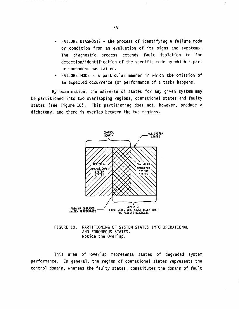
36
fying a fa signs and
FAILURE DIAGNOSIS - the process of ident or condition from an evaluation of its
lure mode symptoms.
The diagnostic process extends fault isolation to the detection/identification of the specific mode by which a part or component has failed. FAILURE MODE - a particular manner in which the omission of an expected occurrence (or performance of a task) happens.
By examination, the universe of states for any given system may be partitioned into two overlapping regions, operational states and faulty states (see Figure 10). This partitioning does not, however, produce a dichotomy, and there is overlap between the two regions.
CONTROL M I N
ALL SYSTEM STATES
WRAiN OF ERROR DETECTION, FAULT ISOLATION,
AND FAILURE DIAGNOSIS
AREA OF DEGRADED SYSTEM PERFORWNCE
FIGURE 10. PARTITIONING OF SYSTEM STATES INTO OPERATIONAL AND ERRONEOUS STATES. Notice the Overlap.
This area of overlap represents states o f degraded system performance. In general , the region of operational states represents the control domain, whereas the faulty states, constitutes the domain of fault
37
detection, fault isolation, and failure diagnosis. The above definitions can now be rewritten so that they are in terms of these states.
FAULT DETECTION - the identification of within the region of faulty states. FAULT ISOLATION - identification of a c within the region of faulty states malfunction of a specific module or comp
a system state lying
ass of system states which classify the ment.
FAILURE DIAGNOSIS - identification of a system state within the region of faulty states which classifies a specific failure mode of the malfunctioning module or component. STATE IDENTIFICATION - the determination of the condition or mode of a system with respect to a set of circumstances at a particular time.
In addition to redefining some of the diagnostic-related elements, one can also express the concept of control in terms of system states.
CONTROL - the identification of a current system operational state and the subsequent adjustment of the system so as to maneuver it to another desired operational state.
From the above discussion the following, self-evident conclusion results:
All types o f detection associated with error perception, fault isolation, failure diagnosis, and system control are classes of state identification.
This conclusion is quite important in that it allows the grouping of the various facets of machine diagnostics, fault detection, fault isolation, and failure diagnosis under the more general topic of state identification. Additionally, since detection for control purposes is also a class of state identification, the importance of considering both the machine diagnostics and control in an integrated fashion is emphasized. Therefore, there exists a common denominator, state identification, around which this study is logically focused.

38
State Identification Process Hierarchy
One can specify a hierarchy of elements that are necessary for the state identification process. First, at the lowest level, information about the system or machine in question must be gathered. Second, once this information has been gathered, it must somehow be reduced to a manageable set of relevant features. Finally, at the highest level, that set of features can be used to perform the state identification. This hierarchy of functions is shown in Figure 11.
STATE IDENlIFICATION
I INFORH4TION REDUCTION I I INFORMTI ON ACOUI S IT ION
I MCWIME OR SYSTEM I FIGURE 11. THE HIERARCHY OF PROCESS REQUIRED FOR STATE
IDENTIFICATION
Information Acqui sit ion
The potential sources of information about a given system or machine necessary for state identification are: specifications , hi story, sensors, and inspection. Optimally, all of these are utilized in the state identification process for machine diagnostics.
Specifications. Specifications are those documents which define the normal operating characteristics of the system or machine. Deviations from this norm may be caused by component failures, design errors, or both.
If a given system is operating according t o specifications, it is in that sector within the region of operational states which does not

39
overlap with the region of faulty states (see Figure l o ) , otherwise it is in the region of faulty states. The specifications define the performance explicitly for the system controller, and implicitly for the system fault detection mechanism.
History. History about a system or machine's performance can be of a short-term or long-term nature. Short-term history represents those events which are related to one another and take place within the physical or characteristic time cycles of the machine. For example, all events occurring within the decay time for a pendulum might be considered short- term history. Long-term history consists of those events which occur in a time frame greater than that considered to be short-term (as previously defined). Observation of all events, whether they are of short-term or long-term historical nature are made using sensors or by inspection (see below).
Sensors. The transducers that measure the various physical parameters. Sensors may either be permanently instal led on-board a machine or used as part of test instrumentation. The sensor output information i s often called raw data. This raw data must be reduced to a set of features in order to perform state identification for diagnostic or control purposes.
Inspection. Inspection techniques are often used in lieu of sensors. In effect, a human serves the function of a wide-band sensor. Some tools are available to assist the human during the inspection process. The physician's stethoscope is an example of such a tool.
Information Reduction
Having acquired information about the performance of a machine or system, it must be subsequently processed and reduced to produce a set of features from which to perform the state identification. Usually, this part of the process involves the reduction of the information by removing that which is redundant or irrelevant. Sometimes data from several

40
sources are combined to generate features which cannot be or which have not been physically measured at a single place or time. A commonplace example of this is the combination of sensory data about a machine, along with its long-term history, in order to derive a feature which describes a machine's failure trends.
There are two principal means by which this reduction of information takes place, signal processing and/or human expert analysis. The difference between these two approaches may be seen simply as the difference between machines and humans. Signal processing can be accomplished in a number of machine domains:
Analog electronics (continuous or discrete), Other analog domains, Digital electronics (hardware only), Hardware and software.
Human expert analysis may be accomplished with or without the assistance of mechanized tools. A mechanic listening to the noise of an automobile engine to discern the tapping of a valve exemplifies the later case. An automotive engineer observing the output of an acoustic spectrum analyzer to make the same determination represents the former case.
State Identification
Having acquired information about a system or machine, and subsequently generating a set of relevant features, the state identification must be performed. As is the case with information reduction, the same identification can be carried out either by humans or automated devices.
In general, there are three approaches for automated state identification :
1. Pattern recognition (with the most trivial case being a table 1 ookup)
2. Nonlinear filters (with the simple algorithm representing the most trivial case)
3. Expert systems.

41
In the specific cases where state identification is used for error detection or fault isolation, a fourth technique is at our disposal, i.e., voting. In the voting process, a society of identical hardware modules operate in parallel to high1 ight any nonconformists (malfunctioning modules) .
Human-based decisions (state identifications) are the most common in the diagnostic/maintenance areas. In the vast majority of these cases, the expert has no assistance (other than perhaps another human expert). Recently however, the use of computer expert systems as decision aids is gaining acceptance. Witness, for example, the increasing commercialization of computer-based expert systems to assist in medical diagnosis.
Summary and Conclusions
In an effort to find a common denominator for the various aspects of machine diagnostics (namely fault detection, fault isolation, and failure diagnosis), it was determined that all were classes of the more general process of state identification. In addition, it was concluded that detection for control purposes was also a class of state identification.
The process of state identification can be thought of as a hierarchy. First information must be gathered about the system in question. Then, the information must be reduced to a set of features. Finally, based upon those features, an identification of the system state may be accomplished.
Viewing this hierarchy from the perspective of machine diagnostics versus machine control, we can gain insight into the interaction between those two functions. Revising the pyramid of Figure 11 we obtain that of Figure 12. It is evident from the above discussion that machine control requires many of the same elements as do machine diagnostics. As shown in Figure 12, there is every reason to expect that a sharing of hardware between the control and diagnostic functions is both possible and desirable. Reliability theory tells us

42
that the addition of any component into a system will always increase the likelihood of failure--even though the component may serve a diagnostic purpose (it is possible that system reliability could be increased if the addition of the component in question added redundancy of some type). By allowing control and diagnostic functions to share resources, system reliability is kept to a maximum. Because diagnostics help to reduce system down-time, once a failure has occurred, system availability is improved.
FIGURE 12. MACHINE CONTROL VERSUS MACHINE DIAGNOSTICS. NOTE THE OPPORTUNITY FOR SHARING RESOURCES
Taking the elements from the above hierarchy and using the classifications discussed earlier in this section, Table 2 is formulated. We are now in a position to use this classification as a tool for organizing the results of our diagnostic survey.
SSME Diaqnostic and Maintenance System Overview
This section presents a brief description o f the SSME diagnostic and maintenance system. It should be noted that the current maintenance/ diagnostic structure is highly complex. In the interest of brevity, the elements chosen represent rather coarse groupings of the numerous re1 ated components. Nevertheless, it is felt that the categorizations are accurate and that the description is therefore a good representation of the diagnostic system.

43
TABLE 2. BREAK-DOWN OF THE DIAGNOSTIC HIERARCHY
AUTMTED OECISION
HUUN EXPERT OP IN I ON
SIGNAL PROCESSING
HI" EXPERT ANALYSIS
DIAGmKTIC
PAlTERN RECOGNITION MONLEAR FILTERS EXPERT s v s m VOTING SYSTEMS HUUN ONLY MCHINE ASSISTED MALOG ELECTRON ICs OTHER ANALOG M I N S
DIGITAL ELECTRON1 CS HUMN ONLY MCHINE ASSISTED
INFOR(UT1ON REDUCTION
t ~~
I SPECIFICATIONS I 1 I
- -. . . . . . I SHORT TERM LONG TERn
TEST INSTRUMENTATION
HISTORY
SENSORS INFORMTION SOURCES ON-BOARD
I H W ONLY MACHINE ASSISTED INSPECTION
The diagnostic system elements for the SSME may be broadly categorized as either "on-board" or "ground-based". For the sake of this discussion, by the term "on-board" we mean those diagnostic elements that are physically close to the engine, whether it is flying on a Space Shuttle or operating on a test stand. "Ground-based" elements of the diagnostic and maintenance system are those that are not considered to be on-board ("everything else").
In addition to the "ground-based" versus "on-board" categorization of the SSME diagnostic elements, they may also be classified according to the diagnostic hierarchy discussed in the previous section. There are a number of levels in the hierarchy, the lowest of which is the plant level (the level containing the engine itself). The next-to-the-bottom level can be thought of as the information gathering level. All elements which have a role in the acquisition of information about the plant's (engine's) performance belong to this level. Control actuators also reside at the information gathering level. The next-to- the-highest level is termed the information reduction level. It is here that any signal processing or conditioning occurs. Finally, the highest

44
level is termed the decision level. At this level, diagnostic and control decisions are made.
Based upon the previously described hierarchical organization we can identify (albeit somewhat broadly) the various elements that comprise the diagnostic system for the SSME. Such an overview is given schematically in Figure 13. It must be noted that those elements which are classified as on-board (including crew) are meant to apply to test stand firings as well as in-flight service.
I I b b I -. nm L f U L
FIGURE 13. OVERALL SSME DIAGNOSTICS AND MAINTENANCEPICTURE
Information Gatherinq
There are two on-board elements which provide the function of data acquisition: crew perceptions and on-board sensors. The crew perceptions are those observations of the flight crew on the Orbiter, and the support staff during test stand engine firings. These observations

45
are results of the physical senses and should not be confused with information presented to the crew by the diagnostic subsystems.
A number of on-board sensors are used primarily for control purposes. The remaining sensors are dedicated to diagnostic functions. Some of the control related sensor outputs are also used for diagnostic purposes.
Aside from the data acquisition function, there are on-board elements for data telemetry and data recording. Nearly all sensor outputs are ultimately telemetered for ground-based analysis. A number of these data are also recorded on-board the Orbiter.
On the ground-based side, a large amount of diagnostic data comes from between-flight inspections. Data acquired by on-board subsystems are ultimately integrated with the results of ground-based inspections and engine repair actions to establish the engine flight and service history. This historical data represents a valuable information pool for detailed analysis.
Information Reduction
All of the data, whether acquired by sensor, observation, or between flight inspection must be reduced to a manageable set of features so that the appropriate diagnostic or control decision may be quickly and accurately made. Sensor data is characteristically reduced using signal processing techniques such as time integration or low-pass filtering. Observations and inspection results are typically reduced by the inspection specialists through the use o f heuristics.
Diaqnostic Decisions
The on-board diagnostic subsystem uses a basic form of pattern recognition. A table of "red lines", dynamically adjusted for changes in the engine's operational modes, is employed to flag potentially dangerous conditions and dictate responses. Similarly, the crew reactions represent a human pattern recognition resulting in we1 1 practiced responses.

46
Currently, the ground-based analysis employs an analytical model of the engine combined with heuristic-based decisions to identify potential trouble spots. This information is used to some degree to direct the between-flight inspections, and aids in the maintenance evaluations and repair decisions.
Summary
This section has presented a high level overview of the SSME diagnostic and maintenance system. The various diagnostic and maintenance elements as well as their interactions (or possible interactions) have been described and are depicted in Figure 13. The intent of the state-of- the-art diagnostic survey is to identify possible techniques to improve the performance of those elements and/or to improve the quality of their interconnections.
Survev Fi ndi nqs
This section presents the significant findings and highlights of the state-of-the-art diagnostic survey. These findings are broken down into three major application areas:
1. Liquid-fueled rocket engines, 2. Aircraft, 3. Non-aerospace industries.
Within each application area, the findings are further organized according to the hierarchical classification discussed in the previous sections .
Liquid-Fueled Rocket Enqines
The principal sources of information for this part of the survey were rocket engine manufacturers, instrumentation vendors, Battel le experts, and NASA reports.
47
The SSME is unique in that is the first truly reusable rocket engine not on an experimental vehicle. This fact, combined with a design which allows for smaller error margins than previous rocket engines, has dictated a much more comprehensive diagnostic and maintenance philosophy than any of its predecessors.
Data Acquisition. The vast majority of the sensing and instrumentation techniques are based upon well-seasoned approaches. In the case of on-board devices, such well-established transducers as thermocouples, pressure sensors, accelerometers, etc. are typically used. The data from these transducers are usually telemetered for ground-based analysis. Historically, manufacturers have not had a great deal of confidence in on-board instrumentation. Rocketdyne is currently under contract with NASA to develop new instrumentation as a part of an advanced condition monitoring system.
Ground-based inspections are characteristically manual in nature. Some instruments such as mass spectrometers have found application in the isolation of gas leaks. Some new techniques for data acquisition have been proposed and/or are under development, but none o f those are yet considered to be mature products.
Siqnal Processinq. Because of the basic nature of the diagnostic systems employed on prior rocket engines, minimal on-board signal processing techniques were used. The techniques used are basic in nature and have as their objective the enhancement of the signal-to-noise ratio or sensor signals. Ground-based analyses of telemetered data characteristically employ more sophisticated approaches.
Diaqnostic Techniques. The sophistication o f the diagnostic techniques used on-board previous rocket engines has been minimal. The most common real-time monitoring technique was based upon the violation o f limits or "red lines". Post-flight analyses, were usually more thorough, relying on tools such as computer simulations.

48
Hiqhliqhts. Items of particular interest which were obtained during.the liquid rocket engine portion of the survey include:
Awareness of Need for Diagnostics. All of the manufacturers of rocket engines that were interviewed (Rocketdyne, Pratt and Whitney, and Aerojet) indicated an awareness of the need for comprehensive diagnostics on reusable engines. Rocketdyne, due to its involvement with the SSME, has already embarked on the development of a comprehensive condition monitoring system. Both Aerojet and Pratt and Whitney intend to develop such systems on future engine programs.
Current SSME Diagnostics. The engine monitoring system currently employed on the SSME has been successful from the standpoint of crew/vehicle safety. However, it is labor intensive and does not lend itself well to the quick turnaround objectives of the STS program. The on-board diagnostics are based upon violations of a series of safety limits ("red lines") some of which are dynamically allocated. The on- board sensor set includes the following:
temperature - resistive temperature detectors, thermocouples pressure - strain gauge, piezoelectric tachometer - magnetic pickup position - potentiometers, RVDT, LVDT vibration - piezoelectric accelerometer flowmeter - turbine calorimeter - thermopile radiometer - foil.
These sensors are considered by Rocketdyne to be adequately reliable. Data from some of these sensors are telemetered for ground- based recording at 20 millisecond intervals during engine firings. The ground-based portion of the diagnostic system is centered around a series of routine and periodic inspections. The routine inspections include the following:
external inspection internal inspections - HPFTP, HPOTP, MCC

49
leak tests automatic/electrical checkouts.
Borescopes are used for some of the internal inspections. Instrumentation required for leak tests includes flowmeters and mass spectrometers. The periodic inspections involve the removal of either the HPOTP, HPFTP, or both. During this activity turbine blades are inspected using optical microscopy, and the respective preburner sections are inspected visually and with concentricity gauges. In addition to the physical inspections of the various engine components, the recorded flight sensor data is reviewed to identify anomalies. The results of this review are communicated to the inspection team when any action is deemed necessary.
Future SSME Condition Monitoring System. Rocketdyne is currently under contract with NASA LeRC to develop an advanced engine condition monitoring system. The first phase of this study involved an analysis of failure reports for a number of liquid-fueled rocket engines, including the SSME, 5-2, H-1, F-1, RS-27, Thor, and Atlas. The failure reports were reduced by successive screening and the resulting reports categorized into sixteen general failure types.
bolt torque relaxation coolant passage splits joint leakage
hot-gas manifold transfer tube cracks high torque cracked turbine blades failure of bellows loose electrical connectors
bearing damage tube fracture turbopump face seal
lube pressure anomalies valve fails to perform valve internal leakage regulator discrepancies contaminated hydraulic
1 eakage
control assembly.
Sensors were subsequently evaluated based upon their ability to aid in the detection of the sixteen failure groups. An implicit philosophy during this selection process was that one sensor (or group o f

50
sensors) would be dedicated to each failure mode. A number of state-of- the-art and novel concepts were identified. The sensors selected from those concepts were:
fiberoptic deflectometer optical pyrometer digital quartz pressure
isotope wear detector holographic leak detector tunable diode-laser spectrometer thermal conductivity leak
ultrasonic thermometer exo-electron fatigue
optical tachometer connector continuity
ultrasonic flowmeter
sensor
detector
detector
checking particle analysis.
Ultimately, the first three of these concepts were identified for development and testing. This program is currently in progress. Another of the sensors mentioned above, an ultrasonic flow meter, was tested during an NSTL test firing. Because of problems arising from the sensor mounting, a duct rupture occurred precipitating a catastrophic engine failure.
In addition to the identification of applicable sensors, the study identified and evaluated the required signal processing techniques for use with sensors to isolate the various failure modes. These techniques are:
amplitude histogram RMS histogram filtered histogram cross correlation transfer function integral over threshold product histogram ratio histogram Cambell diagram
differentiated histogram phase diagram histogram time profile power spectrum density
RPM profiles
The various instrumentation vendors interviewed provided information regarding many of the currently implemented SSME and aircraft

51
test programs. However, little information was obtained regarding new or novel instrumentation concepts.
Ultrasonic Doppler Vibration Sensor. Under contract with NASA MSFC, Battelle's Columbus Division developed a shaft vibration sensor and successfully tested it on a 3-2 rocket engine. The sensor was of a non- invasive nature and determined the velocity of shaft vibrations by measuring doppler shifting from reflected ultrasonic waves. Although a success, this sensor was never developed further or utilized.
Aircraft
Sources for this part of the survey included interviews with experts from the military, commercial air carriers, airframe manufacturers, engine manufacturers, and instrumentation vendors. Information was also gathered from literature and interviews with Battelle experts.
Aircraft engines and their diagnostics have received considerable attention over the years. This attention is due to a number of factors, including the military's emphasis on weapon system availability, the civilian air carriers' push to minimize maintenance costs, and the FAA's desire to assure safety and reliability. Consequently, this part of the survey yielded a good deal of relevant information.
The current diagnostic/maintenance phi losophies in the Air Force and the civilian air carriers are similar. The Air Force is attempting to establish a policy termed "retirement for cause". This concept is most easily described as an interactive preventative maintenance program. Component failures are carefully analyzed and accurate life indicators are derived for the engine components. The components will then be replaced only when a component is deemed to have degraded sufficiently that it will not last until the next periodic maintenance cycle.
The air carriers have a slightly different approach to maintenance. Given the need to reduce ground time and keep the aircraft flying as much as possible, a modified life limit approach to maintenance seems to prevail. An engine is used until a component failure occurs,

52
albeit in some cases an incipient failure, or until life limits dictate a scheduled repair cycle. If the engine is being repaired after a component failure, additional components which would exceed their life limit prior to the next scheduled repair cycle may be replaced.
Both the military and the commercial carriers employ a multi- tiered maintenance structure. The first level is that of the flight line at which major modules are replaced. A second level is responsible for troubleshooting the modules that have been replaced so that they may be quickly placed back in inventory. The third (ultimate) repair level is that of the specialized shops. This level may also include the equipment vendors. Here the damaged components are repaired and returned to the inventory o f good parts.
Data Acquisition. Commercial aircraft engines all come equipped with an array of accelerometers, temperature sensors, flow meters, pressure transducers, and tachometers. The presence of some of those transducers is due to FAA requirements placed on the manufacturers. While all of the airlines use the majority of the installed sensors, there has been some mistrust of the accelerometers. Historically, they have experienced high false alarm rates. As such, at least one airline removes them upon receipt of new engines. The sensor manufacturers insist that the current generation of sensors exhibit high reliability. Their claims seem to be substantiated by the number of airlines that do use the entire sensor package for sophisticated analyses such as trending.
Military aircraft engines usually carry many o f the same transducers as commercial engines. They serve both control and diagnostic purposes.
In the area of ground-based test, vi sua1 inspections, borescope inspections, x-ray checks, eddy current checks, and oil analyses all find application. Some sophisticated instrumentation systems are employed to acquire data from engines in test cells. Temperatures, hot-gas flows and pressures, and other similar data are gathered for off-line analysis.
Siqnal Processinq. The signal processing employed for data from on-board sensors is centered around the enhancement of signal -to-noise ratios. Techniques such as low-pass, high-pass, and band-pass filtering

53
are common place. Features are sometimes generated using straight- forward approaches such as integrating acceleration signals to derive velocity information. Ground-based instrumentation employs similar signal processing approaches.
Diagnostic Techniques. The most common approach employed for on-board jet engine diagnostics relies on a table of limits. When a limit has been exceeded, the appropriate alarm is signaled and the response, if any, initiated. Recently, this approach has been extended or supplemented by some carriers who perform limited on-board trend analysis. Data gathered by on-board sensors are recorded at regular intervals (ranging from several seconds to several minutes). Trends are calculated in order to estimate when the measured parameters will exceed their "red lines". This estimate may be modified to allow for changes in the rate o f degradation. Some air carriers are now relying on information from ground-based trend analyses to conveniently schedule engine repair.
One diagnostic technique used by both the military and the civilian air carriers merits discussion. This technique is referred to as "gas path analysis". Developed and popularized by Hamilton Standard, the approach involves the optimal estimation of the state, and subsequently the health, o f jet engines. In practice, a mathematical model is developed which represents a simulation of a particular engine. Sensor data are then used as a gauge for the optimal adjustment of the model parameters. When those parameters exceed acceptable limits, a failure i s
decl ared . At Kelly Air Force Base, the Air Force uses such a system for
test cell analysis of engines. TWA has also recently purchased such a system from Hamilton Standard. In addition, TWA has initiated a program whereby sensor data is telemetered from their latest generation of aircraft, and a quasi-real-time analysis is performed to assess engine performance. The air carriers rely heavily on an integrated system where in-flight data is analyzed and used in conjunction with ground-based test results to plan maintenance actions.
An on-going research and development effort is focused on the concept of an expert system (artificial intell igence based computer program) for jet engine diagnostics. This concept is based on the

54
transfer of human expertise to the expert system computer program. Although these systems are maturing very rapidly, they are not yet considered to be off-the-shelf.
Hiqhliqhts. Items o f particular interest which were obtained during the aircraft portion of the survey include:
USAF Retirement for Cause. The USAF is in the process of implementing a maintenance policy referred to as "retirement for cause". In short, this policy requires that an experimental analysis be performed on each batch of engine components in order to accurately understand and predict the life limits in the presence of the potential failures. For example, the level of propagation that a crack in a turbine vane must attain before failing will be empirically determined. Once these life limits are known (or at least estimated), the engine monitoring systems and periodic inspections are used to track engine component failures. Only when the life limits are approached are the faulty components rep1 aced.
USAF On-Board Diagnostic System. An on-board engine monitoring system similar to the AIDS (see below) was experimentally implemented on five tactical F-15A aircraft (F100 Engines). The parameters monitored were :
augmenter fuel pump discharge rear compressor
augmenter permission fuel pressure fuel pump inlet temperature burner pressure main oil temperature fan/core mixing pressure compressor exit static fan exit duct pressure fuel pump boost pressure fan exit duct temperature fuel pump inlet pressure fuel pump discharge pressure main breather pressure power level angle number four bearing scavenge
pressure variable vane pressure
temperature
diffuser case vibration inlet case vibration
position. pressure

55
The on-board data acquisition system monitored these parameters and subsequently transferred the data for ground-based analysis. Such analyses, in conjunction with ground-based tests were used as the basis for a maintenance program. On the whole, the experiment was considered to be successful.
Experience with Commercial Carriers. Three domestic air carriers were interviewed in addition to making a review of literature describing some of the maintenance policies of European air1 ines.
Nearly all carriers utilize a variation of the aircraft integrated data system (AIDS). This data system was specified by ARINC and has the following attributes:
diagnostic information is centralized some data is available for in-flight analysis data is recorded on a cassette tape for later ground-based analysis.
A number of carriers have implemented engine monitoring systems which are also integrated with the AIDS. In these systems, important engine parameters are monitored in-flight such as gas pressures and temperatures, fuel flows, rotor velocities, lubricant temperatures, and vibrations. Engine condition reports are available during flight to the flight engineer for short-term trending analyses. Long-term trending is performed using the AIDS data tapes during ground-based analyses.
In addition to the engine monitoring systems, ground tests and inspections are used to identify failures and trends. Ground-based inspections may include:
visual inspection eddy current checks borescope inspections spectrographic oil analysis x-ray checks ferrographic oil analysis
The general consensus in the European air carrier community is that such sophisticated diagnostic and maintenance programs are cost justified. The domestic air carriers are not quite so aggressive. TWA,

56
however, has a maintenance and diagnostic program which is very much along the lines of the European carriers. United Air Lines on the other hand, seems to employ a more conservative, people intensive approach to maintenance and diagnostics.
Gas Path Analysis. Hamilton Standard Division of United Technologies has been marketing a computer software package called Gas Path Analysis. This software relies upon a linearized mathematical model of a specific jet engine to estimate the performance characteristics of the engine's constituent modules using measured input parameters such as temperatures, pressures, spool speeds, and fuel consumption. The program also estimates the performance of the various sensors that are used to acquire the data used in the analysis.
The mathematics of gas path analysis is based on the premise that it is possible to linearize any thermodynamic cycle model by deriving matrices of influence coefficients which relate deviations in measured parameters and component per 'ormances to coefficients describing component faults for each of the eng ne's operating points. The equations solved are:
A = H X + B Y = Ge Xe
where X = (E) and H = (HelHs)
The significance of the various variables is as follows:
Z is a column vector of measurement deviations or deltas Y is a column vector of performance deltas for the engines' constituent modules Xe is a column vector of engine fault deltas Xs is a column vector of apparent sensor errors He and Ge are the matrices of coefficients derived from the engines' mathematical model Hs is a matrix of sensor fault coefficients B is a random vector denoting sensor non-repeatability.
The dimensions are such that there is an over-specified set of equations which are a result of analytical redundancy in the measured

57
parameters. errors as well as engine component malfunctions.
It is also this fact which allows the determination of sensor
A number of air carriers use this technique for ground-based analysis. Some European carriers and TWA use the gas path analysis program for analysis of flight data. Other carriers and the USAF use it only for test cell analysis of engine performance.
Sensors and Instrumentation Development. The area of sensor development receiving the greatest amount of attention for flight applications is that of fiber optic sensors. These sensors are especially desirable from the standpoint of weight and noise immunity. At this stage of development, however, the fiber optic connector technology is not sufficiently robust to allow widespread use on flight engines. A recent NASA study has examined applications for fiber optic sensors such as:
rotary encoders optical tachometers rotor blade tip clearance optical temperature sensors (pyrometers) .
Optical pyrometers have also been used in experiments to accurately determine turbine blade life. Solar Turbines Incorporated has provided such instrumentation for a number of these experiments. Optical clouding due to the presence of combustion products has been the principal operational drawback o f this type o f instrumentation.
In the more general area of data acquisition, a number o f instrumented engine core test programs have been carried out. An off-the- shelf system for telemetering data from an engine rotor is available from Acurex Corporation. These systems are not considered to be sufficiently robust for flight applications.
Expert Systems. There are at least two programs underway for the development of rule-based expert systems for jet engine diagnosis. On the military side, the Air Force has been funding such a development at General Electric. In the commercial sector, Boeing has also been developing an expert system for jet engine diagnosis.

58
Non-Aerospace Industries
Information sources for this part of the survey included interviews with experts in fields ranging from medical electronics to transportation systems. In addition, interviews were conducted with Battelle experts and relevant publications were reviewed.
In general, the industrial sector has been somewhat slow in recognizing the potential of machine diagnostics, but recently, there has been an increasing emphasis in this area. The motives for this interest are varied. For example, NRC regulations have had a strong influence on the nuclear power industry while customer support issues have had an impact on the use of diagnostics in the automobile industry. Whatever the motives, some interesting techniques have resulted which may ultimately be of value to the SSME program.
Data Acquisition. In the area of transducers, most industries have embraced the proven sensors , e. g . , accel erometers , t hermocoupl es , etc. The manufacturers of those devices have been. developing more reliable and "ruggedized" transducers and recognize that their sensors will be located in progressively more hostile environments.
In terms of sensing concepts, a number of techniques in development or use merit discussion. These concepts are described in the following paragraphs.
In the nuclear power industry, a device known as a miniature accelerator or MINAC has been developed for radiographing pump housings. The device is placed inside the housing and photographic film is placed around the outside of the housing. Once activated, the MINAC generates radiation that penetrates the pump and exposes the film--from the inside- out.
For the conventional power industry, Solar Turbines Incorporated is under contract with the Electric Power Research Institute to instrument a gas power turbine with an optical pyrometer. The pyrometer is positioned to scan the passing turbine blades and provide measurements leading to accurate predictions of the blades' life.
A number of novel fiberoptic-based sensors have been under development . An exampl e of this is the 1 aser-doppl er-vel ocimeter (LDV)
This device has simplified a difficult imaging problem.

59
which measures the velocity, not speed, of moving material. The material being measured can be a solid or a fluid. Because of its optical nature, the information can be communicated from the moving medium to the sensor by optical fibers. This sensor is already finding application in the manufacture o f synthetic fibers.
A new class o f semiconductor devices for measuring the presence of various elements has been under development. This device is called an ion selective field effect transistor (ISFET). These devices have been proposed for measuring such parameters as hydrogen concentrations in gases, and glucose levels in human blood. ISFETs have certain stability problems that have not as yet been resolved.
Cooperative sensing schemes are finding increased usage. The principal behind this concept is not new: the design o f the system or component to be examined is altered so as to provide a clear, unmistakable signature which is easily monitored. Putting a tracer in a gas to measure concentrations and flows represents a well developed application of this technique. In a more recent example, bearing balls where magnetized to allow the monitoring of their behavior by simple magnetic field sensors.
For the storage of performance data, the memory card, an extremely portable device, is gaining popularity. This device is comprised of a microcomputer and nonvolatile data memory in a very small package (typically the size of a credit card). Memory cards, because they are inexpensive and portable, can permit the highly accurate tracking and monitoring of modules and components as they progress through the repair cycles. Unfortunately, the storage capacities o f the data memory are still limited.
Vibration monitoring is common in numerous industries ranging from petrochemical plants to paper mills. For example, at Exxon's petrochemical plant in Baytown, Texas much of the machinery is continuously monitored using a minicomputer and on-board accelerometers. The signal levels of the accelerometers are analyzed to determine trends. Based upon such trends, maintenance can be optimally scheduled. In this same plant, such phenomena as pump cavitation were also detected by more careful analysis of the accelerometer signals. However, the ability to gather this additional information has not been integrated into the monitoring system.

60
Sianal Processinq. In the realm of signal processing, the most impressive developments have been in the area of hardware. Integrated circuits are now available which perform such functions as real-time digital filtering or real-time Fast Fourier Transforms. A manufacturer of charge-coupled-device (CCD) arrays , EG&G Reticon, a1 so manufacturers semiconductor devices which perform many of the filtering and analysis functions in the discrete time analog domain. Prior to the availability of those devices, these filtering techniques were only possible using digital electronics.
In the continuous time domain, a number of sensors have been developed for specific applications to perform filtering functions in a non-electronic fashion. One well developed example o f this approach is the use of a tuned acoustic transducer for the monitoring of predetonation in GM automobile engines. This approach was used by GM in a effort to minimize production costs.
In the field o f automated inspection systems a good deal of progress has been made in image processing and image interpretation. Commercial systems are now available for the automated inspection of pieces on an assembly line for manufacturing defects. Similar techniques have been developed for the autonomous inspection of printed circuit boards. This area will likely continue to evolve due to the recent successes.
Recent research in the human factors associated with display technology is directed toward the presentation of high level information, rather than machine parameters, in a graphical format. In industries such as nuclear power, the operators of the systems need diagnostic information in a high-level and unambiguous format, thus, permitting the decisions to be made quickly and accurately via human pattern recognition.
Diaqnostic Techniques. The approaches used in the industrial sector for making diagnostic decisions span the entire spectrum, from the simple table lookup technique employed on most automobiles, to expert system computer programs for the diagnosis of failures in train locomotives. Of the information gathered during this part of the survey,

61
there are several concepts worth mentioning. These make up the remainder of this section.
General Electric Corporation has developed an expert system (computer program) for the diagnosis of failures on railroad locomotives. In this approach, the computer program was written to reason and draw conclusions based upon a set o f rules. The set of rules is derived from interviews with human experts in the area (that of repairing GE's locomotives). In operation, the expert system guides the actions of a repair technician. This is only one of several diagnostic "experts" that have been developed: Westinghouse's Steam Turbines Division has developed a diagnostic expert system for steam turbines. The Westinghouse program, moreover, identifies sensor malfunctions as we1 1 as turbine component failures.
On-going research in the area of non-linear diagnostic filters promises to improve their performance by increasing sensitivity and reducing false alarm rates. In one particular effort involving Case Western Reserve University and Bailey Controls Division of Babcock and Wilcox, an industrial heat exchanger will be the test bed for an improved non-linear diagnostic filter. The benefits of such research efforts are likely to be incremental in nature, but available in the relatively short term.
The commercial application of pattern recognition based upon statistically derived and/or empirically determined features has been a reality for a number of years. The benefits of this approach is that the computation times for making decisions about a machine's performance can be very brief. Other computationally oriented techniques, non-linear diagnostic filters and expert systems, typically require substantially more time than pattern recognition. Historically, most pattern recognition systems have been custom tailored to the signatures of single specific machines, rather than, for example, other identical machines. This shortcoming has been addressed through the use of adaptive pattern recognition systems.
Vibration trend analysis is becoming a commonly used technique, especially in industries such as petrochemicals and paper manufacturing. This technique usually involves the monitoring of vibration sensors (most often the integrated outputs of accelerometers) to watch for change. The

62
rate of increase is estimated, and repairs scheduled according to the estimated time until a failure occurs.
Predictive diagnostics based upon ferrographic analysis of lubricant has been a reality for a number of years. This technique is based upon the gathering and analysis o f wear particles to determine the mechanisms and severity o f wear. While there are machine mounted sensors available for automated ferrographic analysis, the most thorough analyses are performed off-line using bichromatic microscopy.
Voting systems have been used to address anticipated failures (i.e., those failures that result from known component failure modes). However, unanticipated faults due to such causes as design errors cannot be addressed by voting systems. The more complex a machine, the greater is the likelihood of latent design errors.
Recommendations
Given the nature of the SSME environment and maintenance structure, several of the approaches and techniques identified in the previous section are recommended. We will hold to the same organization that has been used throughout this report. These recommendations are further summarized in Table 3.
Data Acquisition
To the extent possible, those existing on-board sensors which have experienced reliability problems, should be considered for replacement. As existing sensors are continually improved for sensitivity and durability, they should be examined and, as warranted, tested and considered for use on the SSME. A sensor data base would be beneficial for both the SSME, and for future rocket engine development programs.

63
TABLE 3. SUMMARY OF DIAGNOSTICS RECOMMENDATIONS
Diagnostics Category
Recommendations On-Board Ground-Based
Data Acquistion More Reliable Sensors
Increased Bandwidth for Existing Accel er- ometers and Trans- ducers (pressure, temperature, flow, and speed)
Additional Conventional Sensors
Extensive Data Record i ng
Continued Development of:
Optical Pyrometer Fiber Optic Deflecto- meter
Ultrasonic Doppler Transducer
Ultrasonic Flow Meter
Signal Processing Improve S/N Ratios by Spectral Fi 1 tering and Noise Cancellation
Diagnostic Techniques
Analysis and Development of Pattern Recognition D i agnost i c System
Continued Development of Isotope Wear Detector
Extension of Isotope Wear Detector Concept to Include Ferro- graphic Analysis
Use o f Tracer Elements (Tritium or Sulfur Hexafluoride) for Leak Detection
Image Processing to Enhance Borescope Inspections
Develop Gas Path Analysis Model of SSME
Evolve Gas Path Analysis Model to Include Non- Linear Diagnostic Filter
Establish and Maintain Integrated SSME Data Base (diagnostic and maintenance)

64
The on-board sensors should be more effectively used. For example, the accelerometers currently on the SSME are only used for the RMS values of their outputs. There is undoubtedly a great deal of information available in the higher frequency harmonics that is not being used. The full bandwidth of all existing sensors should be recorded on board and the data later used for detailed ground-based analysis. It also may be possible to telemeter this recorded data while the STS is on orbit.
It is estimated that upwards of 85 percent of all failures are intermittent in nature. Over the course of our survey, two approaches to the isolation of intermittent failures were identified: marginal testing and extensive logging. The use of marginal testing techniques on the SSME is not feasible. Therefore, we recommend that extensive on-board recording of the engine be performed. By analyzing this extensive amount of data, either on the ground or on-board, intermittent problems may be identified and isolated. In addition, the extra sensors required for such monitoring will augment the analytical redundancy of the diagnostic system.
The sensors proposed by Rocketdyne for the monitoring of turbomachinery should be carried through to application. Specifically, the optical pyrometer, fiberoptic deflectometer, and isotope wear detectors, will significantly improve the information available on the health of the turbopumps. In addition, the isotope wear detector program should be extended to encompass ferrographic analysis. Numerous precedents suggest that this type of analysis would be valuable for predictive diagnosis.
For ground-based inspections, we recommend that tracing elements should be considered to aid in the detection of hydrogen and other fluid leaks. It is felt that this would result in the simplified sensing apparatus.
Signal Processinq
For ground-based tests, image processing should be used to augment certain inspection processes, especially the borescope

65
inspections. It is believed that such techniques could both improve the accuracy, and reduce the time required for inspections.
For on-board instrumentation, more elaborate signal processing will be required. Given the noise environment of the SSME, both spectral filtering and statistical noise cancellation techniques could be used to provide improved signal-to-noise ratios. High signal-to-noise ratios are essential if the existing sensors are to be more fully utilized.
Diaqnostic Techniques
In the arena of diagnostic techniques there are three recommendations, one for on-board diagnosis and two for ground-based analysis. The principal purpose of the on-board diagnostics is to avert rapidly developing, catastrophic failures. Because of the speed of diagnosis and level of accuracy required, pattern recognition is the only realistic technique. To increase the coverage and accuracy of the on- board diagnostic system, a pattern recognition-based diagnostics should be considered.
For ground-based analyses, an effort to improve the analytical model for the SSME should be undertaken. In conjunction with such a model, a non-linear diagnostic filter should be developed. This effort might begin by initiating a gas path analysis program, and improving the analysis on an incremental basis. It may even be possible to run such a program in real-time based upon telemetered data (given adequate computing resources). If the system is sufficiently accurate, detailed trend analysis capabilities could result.
Finally, a thorough and highly integrated data base should be established to track and correlate information about engines and components. Information from on-board sensors, ground-based inspections, repair actions, and component histories should be included. Analysis of this data base must be made highly interactive to be most effective. Ultimately, such a data base could benefit the SSME maintenance staff, the operations staff, and the engine component manufacturers.

66
(This page intentionally blank)

67
SSME DIAGNOSTIC EVALUATION
The third task of the SSME study assimilated the outputs of the SSME failure data review and the diagnostics survey and used this information to evaluate the current SSME diagnostic system. The principal objective of this task was to identify potential means for improving the availability of high-quality, pertinent engine data. This information could be used both in-flight and on the ground to assess the condition of the SSME and its respective components. To accomplish this objective, an analysis tool (Failure Information Propagation Model) was selected to perform a systematic examination of the diagnostic information in the SSME. The Failure Information Propagation Model (FIPM) is discussed in this section. Also included is a description of the initial application of the FIPM to an SSME component.
Issues and Approach
To evaluate the overall SSME diagnostic system, the information gathered during the failure data review and diagnostic survey was integrated and analyzed. At the outset of this evaluation task, the following data were available:
Results of the SSME failure data review Knowledge of the existing SSME inspection and maintenance
Information on sensor research and development underway for
process Knowledge of the current SSME sensors
the SSME Results of the diagnostic survey.
This information provided a sol id foundation for performing the required evaluation.
The first step in the analysis was to select the actual tool or technique to be used. To facilitate selection of a suitable analysis method, an overall approach was defined for the task. The approach adopted centered on addressing several key diagnostic issues. These issues included the following:

68
What additional diagnostic information exi sting SSME sensors?
s ava lable to the
Are there any information rich test points on the SSME that should be instrumented? If so, which sensors should be considered? How can we optimize the placement of additional sensors so as to minimize their total number and cost while maximizing their information gathering potential and reliability? Which instrumentation research and development areas represent the best investment relative to the diagnostic needs of the SSME?
The common denominator for all of the issues mentioned above is an understanding and characterization of the engine failure information and its flow paths.
The major focus of the initial effort on this task was directed, therefore, at finding a suitable means to represent the SSME failure information and at developing a data format which could be easily manipulated to address each of the above issues. The tool which appeared to satisfy all of the proposed requirements was the Failure Information Propagation Model (FIPM). The FIPM concept is discussed in the following subsection.
Failure Information Propaqation Model
The Failure Information Propagation Model (FIPM) is a technique developed by the Battelle Columbus Division to qualitatively evaluate the potential test points in a system. The objective of this qualitative evaluation is to assess the information bearing value of each test point. The FIPM basically divides the system under analysis into its principal components or functions, describes the failure modes for these components , catalogs the physical connections between the components , details the flow of failure information through the various connections, and groups the failure information according to signal properties. It must be emphasized at this point that the FIPM models the propagation of failure information and not the failure itself. The model assumes that

69
the system being depicted is in a near-normal state of operation. The failure information flow is described for the instant of time immediately following a given failure.
The FIPM was initially developed to evaluate the factors affecting image quality in a photographic copy machine. This proprietary study was performed for an industrial client. Due to the nature of the system involved, this analysis was primarily concerned with the electronic functions of the device. Subsequent to this study, the FIPM was applied to an ion chamber and a home furnace. All of this work preceded the FIPM's consideration for this task. As a result of this early work, the FIPM has demonstrated the capability to adapt to a broad range of mechanical and electronic systems.
Three principal applications exist for the output of this model. These applications are:
Evaluation of existing sensor systems to maximize the
Identification of sensor research and development needs to
Design of sensor systems for new devices or components
information yield
target key diagnostic data.
These important features o f the FIPM made it especially attractive for use in the SSME diagnostic evaluation.
FIPM Example
The formulation of an FIPM must begin with the identification of the modules (components or functions) that comprise the system being evaluated. These modules may be piece parts, subassemblies, or subsystems depending on the level of detail sought. In the case of a typical exhaust fan, which is used here solely as an example, the constituent modules are subassemblies which have been selected to illustrate a top- level FIPM. In the case of the high-pressure oxidizer turbopump (HPOTP) FIPM which will be discussed later in this section, the constituent modules general ly are piece parts.

70
The modules selected to illustrate the FIPM concept for the exhaust fan are the AC motor, the fan belt, the fan, the fan bearing, and the frame which supports these components. These elements are shown in Figure 14. The resulting model is very simple in that the AC motor actually has both electrical and mechanical parts, the fan has both blades and a pulley for the drive belt, etc. It is recognized that this model ignores many factors which would be considered in a thorough engineering analysis.
The network of connections between the exhaust fan modules is depicted in Figure 15. As indicated in this figure, the motor is mechanically mounted to the frame and transforms electrical power into mechanical power through friction with the fan belt. The fan belt also is connected by friction to the fan. The fan and frame are joined through the bearing by means of rolling elements. A thermal connection also exists, in normal operation, between the AC motor and the frame. The final element in the network is an air flow path out of the fan.
The failure modes of each of the exhaust fan modules i s shown in Figure 16. It should be noted that these failure modes do not include -r,hanisms which are external to the module. Failures due to such outside
,.AS as fire, explosion, or mechanical damage are not considered. Events such as fire in the fan motor also are not considered since these are actually effects of more fundamental failure modes. It should be reiterated that the FIPM is modeling the situation immediately following a failure and not the longer-term effects and consequences of that failure.
The occurrence of any exhaust fan failure mode produces failure information which can be detected externally to the component and which will, in general, be transmitted to adjacent components. An assessment of the failure information propagations for the exhaust fan example i s shown in Figure 17. It is interesting to note that, in this example, all of the failure modes transmit failure information to all of the other modules. The large amount of failure data which is available at any given connection in the system is evident in this figure.

71
AC Elect& ;1
FIGURE 14. MODULES COMPRISING EXHAUST FAN F I P M
FWI AC Electrk
Motor Fan Belt
1 2 3
\. \ \
m
\. \\
\. \\
\,\\
\. \\ Frame \. \
5 4 = Electrkd Power - Friction + Air Flow 9W- RoiHng Element
Mechanical Thermal
-- ---
Fan Belt FWI -
2 3
m
FIGURE 15. CONNECTIONS BETWEEN EXHAUST FAN MODULES

72
-
AC Electrlc Motor F8n Bett Fan 1 2 3
A. 8*dng A. srpprcla A . B l 8 d e W - B. On B. Br(ngwbmtI0n B. %..kagD
c. 0P.n- D. sha(.dWkdbg
FIGURE 16. A D D I T I O N OF F A I L U R E MODES TO EXHAUST FAN F I P M
\. \\ Key \.
- Electrical Power - Frlctlan
2/G Alr Flow
r
5 4
A. Wear 8- -
= Electrlcal Power - Friction -vb- Alr Flow
Roiling Element Mechanical Thermal
--
1-A.8.C.D 2 4 . 8 3-8
FIGURE 17. F A I L U R E INFORMATION ASSOCIATED WITH EXHAUST FAN CONNECTIONS
r - 14,C.D Fm 1-A.C,D
44.0
2 4 . 0 2-AB 34.8 3 3-A.B
Motor 1-A.0.C.D Fan Belt 2
A. srpprcla B. Ewmk.g.
24.0 3-8
1
A. Bkdkrp 8. 8.r*lg- c. 0P.n- 0. ShoridWlndlng
B. w
Frame
5
I-A.D\. \ Bearing 3 4 4-A.D 4
A. Wear 8. Prmng

73
The failure information in the current example can be further categorized at each connection according to the type of measurement or sensor required for detection. An open winding [lC] or breakage of the fan belt [ZB] could be detected by an ammeter on the electrical line. Similarly, binding o f the motor [lA], a shorted winding [lD], or dirt on the fan [3B] can be detected by a voltmeter across the motor terminals. In Figure 18, the failure information for each connection has been grouped according to the type o f measurement involved. This clustering of the failure information is the final step in the development of the FIPM. Analysis of the data in the model can now be initiated.
. . \ ' . , ' y , 4 A I
Bearing 13A.4Al Frame
A. Wow \.
= Electrical Power - Fr icth 2/G Air Flow ?Rm\- Rdllng Element
Mechanical Thermal
-- ---
U I
FIGURE 18. FAILURE INFORMATION GROUPED BY SIGNAL TYPE FOR THE EXHAUST FAN FIPM
A sensor of the appropriate type would detect any or all of the failure modes within a particular group. It would be necessary, therefore, to provide additional information or to further process the signal to uniquely identify any single failure mode. The process of determining the failure signatures and respective sensor sets is highly detailed and has not been undertaken for the exhaust fan example.

74
Hiqh-Pressure Oxidizer Turbopump FIPM
The high-pressure oxidizer turbopump (HPOTP) was selected as the initial SSME component for evaluation using the FIPM. An HPOTP FIPM was graphically constructed using the steps outlined in the preceding example. The resulting model was quite large due to the complex nature of the HPOTP. A large portion of the initial representation also was color coded for ease of interpretation. Due to both of these factors, the initial HPOTP FIPM is unsuitable for inclusion in this report. An attempt will, however, be made to describe the significant features of this model and the subsequent analysis which was performed. The version of the FIPM which will be described in this section is no longer the baseline configuration for the HPOTP. The reasons for this situation will be discussed. The revised FIPM approach which is currently being used is out 1 i ned in a subsequent subsection.
The original HPOTP FIPM had the following features:
46 modules 100 module failure modes 59 connections 2248 failure information propagations.
A small black and white excerpt of this FIPM is shown in Figure 19. A key for this graphic is included as Figure 20. All of the data comprising the FIPM was displayed on the graphic representation.
Subsequent to the development of the HPOTP FIPM, a preliminary analysis of the HPOTP failure information was performed using a failure information matrix. A portion of this matrix is shown in Figure 21. In this matrix, the rows represent connections (test points) between modules. The columns correspond to specific module failure modes. The data entered in the matrix at the intersection of a given row and column is the failure information types associated with the designated failure mode which can be detected at the designated connection. This matrix was used to develop a preliminary set of test signature equations for the HPOTP.

75
BEARING 1 3 INNER RACE I a. Wear
1 b. P i t t i n g 1
[CAV 2d. 21b [RUB] 2b. 21a
[RAY] 19a AXIAL SPRING CARTRIDGE d . Year: F r i c t i o n
WTER RACE a. Year
FIGURE 19. EXCERPT FROM I N I T I A L HPOTP F I P M
FAILURE S I W L TYPES
COUPLING TYPE
N Y :I tE tE U 'P .F ;1 :R I1
I] Rubbing
' Cracking ;] Ro l l i ng Element b a r ;] Ro l l i ng Element P l t t f n g RW Associated Vibrat ion
'1 Impact '1 Lou Flow o r Pnssure :] S t r e s s - t i r Fatigue Candidate !] Erosion ] High Local Tanpcriture
I] C I V f t J t f m
COUPLING W I F I E R
a OxypIn
a Comon Part
a Melirm
-47 Unanticipated Coupling
Spring
Ro l l ing Element
@ Lubricant
F IGURE 20. KEY FOR I N I T I A L HPOTP F I P M

76
4- c a VIU
* *
P
* I I
i - I - "l

77
The test signatures were formulated by marching through the columns of the matrix. For each column, the rows were examined to determine where failure information resided. The rows also were scanned to identify other failure data present at the connection which exhibited the same signal characteristics (i .e. , high temperature, low pressure, etc.). By careful evaluation of the matrix, it was possible to determine sets of signals which could be used to uniquely identify specific failures. Some examples of the initial results included:
Failure mode 1B = rpm associated vibration Q test point 34 OR = rpm associated vibration Q test point 36 OR = rpm associated vibration Q test point 38
Failure mode 2A = cavitation Q test point 5 AND NOT cavitation 8 test point 1
Failure mode 28 OR Failure mode 3A OR Failure mode 5C = rubbing Q test point 4 .
No attempt was made to determine a unique signature for certain classes of failure modes. In cases such as the turbopump bearings, it is not necessary to know which particular bearing is bad. An indication that any of the four bearings is experiencing degradation is sufficient cause to remove the turbopump from the engine and overhaul the bearings.
Subsequent efforts to specify a set o f diagnostic sensors which would target all of the high-priority HPOTP failure modes, as identified in the SSME failure data review, encountered difficulty due to the need for additional data. The model, as constructed, did not have sufficient detail to adequately describe the failure signals. It was determined that specifying high temperature was insufficient without some sort of associated range. This initial application of the F I P M methodology to a complex mechanical system had also demonstrated the need for more formal definitions and standardized development rules. The definitions and development rules had previously been instituted on an ad hoc basis as the need arose. A decision was reached to restructure the HPOTP F I P M based on a more formal development methodology.

78
Current FIPM Methodoloqy
The current FIPM methodology was developed by the originator of the FIPM concept with major inputs provided by the participants in the initial SSME FIPM activity. A number of FIPM development tools resulted from this process. These tools are included in Appendix A of this report. The allowable types of physical connections, failure modes, signals, and signal parameters are included for use in constructing an FIPM. These allowable values have been selected with respect to fundamental physical properties and laws. Their intent is to reduce the number of arbitrary and possibly confusing choices which must be made during model formulation. Rules regulating the handling of potentially ambiguous situations are also included. It was decided that the new FIPM procedure should be implemented in a data base format. This step was necessary to accommodate the large amounts of information which were projected for the SSME models.
The current FIPM methodology consists of two primary elements. These elements are:
Simplified FIPM drawing FIPM data base.
The present FIPM drawing format summarizes key information about the system being modeled for use during generation and input of appropriate data base records. The data base stores all of the information associated with the FIPM including the items shown on the drawing. The data base, however, permits substantial amounts of additional descriptive and qualifying information to be stored and accessed.
FIPM Definitions
The following terms are used in reference to a failure information propagation model:
SYSTEM - The top-level item or component which is being modeled
MODULE - A subelement or function of the system (analyzed)

79
CONNECTION - A path (mechanical, fluid, etc.) which exists between two modules FAILURE MODE - The physical mechanism or process by which a module ceases to perform its intended function FAILURE INFORMATION PROPAGATION - A description of specific signal characteristics associated with a given failure mode which can be detected at a particular connection.
FIPM Drawinq
The first step in formulating a failure information propagation model is to develop a graphical representation or drawing of the system being analyzed. The principal function of the FIPM drawing is to describe the constituent modules of the system and to identify the connections between these modules. The initial drafts of the FIPM drawing are prepared by technical analysts or engineers familiar with the system involved. The number o f modules included is chosen to be consistent with the overall level of detail required for the. anadysis. The accurate depiction of the system is critical to the overall development of the FIPM. This illustration is the foundation for the entire data base associated with a given system. Careful construction and review of the FIPM drawing minimizes potential corrections and changes to the data base.
The FIPM drawing is composed basically of boxes and lines which connect the boxes. Each box on the drawing represents a particular module. The 1 ines represent the physical connections between the various modules. Additional information is also shown for both the boxes (modules) and the lines (connections) to further identify specific physical details associated with both of these elements. The format selected for the FIPM drawing allows all of the necessary data to be displayed in black and white for ease of reproduction. The key for the current FIPM drawings is shown in Figure 22.
An example of an FIPM module is shown in Figure 23. Each module on the FIPM drawing displays the following items of information:
System code Module number

80
Connection Connection Modifier
Mechanical
~
a Common-Piece
111- Liquid
........ m m 1 Gaseous
Two-Phase ---.- @ o m
@ Hot-Gas
@ Helium
@ Rolling-Element
4 Unanticipnted
[ External
FIGURE 22. KEY FOR CURRENT F I P M DRAWINGS
3 T l - a 8200 IMPELLER NO. 3
W A. FRACTURE VlBRATlON FATIGUE E. FRACTURE MERMAL FATIGUE C. WEAR RUBBINQ WITH [ E m 0 04101 0. WEAR: RUBBINQ WITH [E200 05401 E. WEAR: CAVITATION
1 - SYSTEM
2 - MODULE NUMBER
3 - MODULE NAME 4 - MODULE FAILURE MODES
FIGURE 23. SAMPLE MODULE FROM AN F I P M DRAWING

81
Module name Module failure modes.
For a given system, the module number and name must be unique. An example of an FIPM connection is shown in Figure 24.
Examination o f the line type and symbols associated with specific connections enables the following items of information to be determined:
General type of connection (solid, liquid, etc.) Additional data specifying exact type o f connection Unanticipated connection Connection to external system.
Symbols may be combined as required to completely describe a particular connection.
1 - LIQUID 2 - HYDROGEN 3 - UNANTICIPATED 4 - EXTERNAL
FIGURE 24. SAMPLE CONNECTION FROM AN FIPM DRAWING
FIPM Data Base
After completing the FIPM drawing, the next step is to generate and enter data into the failure information propagation model data base.

82
The current FIPM data base and software are discussed in detail in later sections of this report.
Space Shuttle Main Enqine FIPMs
The initial approach to analyzing the SSME divides the engine into major components (systems) which are examined independently. This process reduces the size of the individual models to a manageable level and also eliminates the crossflow of failure information between systems. The idea behind the current method is to gain diagnostic insights relative to each high-priority item. This data subsequently will be used to make recommendations concerning monitoring requirements for a particular component.
The "SSME Failure Mode and Effects Analysis and Critical Items List" compiled by the Rocketdyne Division, Rockwell International Corporation (Reference 3) includes over 200 SSME components. Developing an individual FIPM for each of these items would not be the most efficient way to analyze the entire engine. Certai.n components, such as propellant ducts and pressurant lines, are relatively simple in nature. These systems can be easily modeled with just a few modules and connections. SSME items of this type are included as modules in the FIPM of the appropriate major component. For example, the high-pressure oxidizer duct i s included with the HPOTP FIPM.
Each system (major component) i s represented in the FIPM data base by a four-character code. These system designations coincide with the Rocketdyne FMEA item numbers (Reference 3, Table 2-1) whenever feasible. The record in the systems data file also indicates any additional Rocketdyne FMEA items which have been included in a particular FIPM system. Components which do not have a corresponding Rocketdyne FMEA number are given a similar four-character code. Confusion is avoided by selecting a number not used by Rocketdyne.
The generation of data for the HPOTP FIPM demonstrated that a very large number of failure information propagation records can be associated with a major SSME component such as the HPOTP. This observation resulted in the creation of separate failure information propagation data files for each major SSME component (system). There is

83
one data file each associated with the systems, modules, connections, failure modes, and references. Information of the appropriate nature is stored in each of these five files for all of the various FIPMs.
The FIPM methodology, as used for analyzing the SSME, includes special provisions f o r hand1 ing the connections between major engine components (FIPM systems). This feature of the technique allows the data flows between systems to be evaluated on a preliminary basis. It also enables the future expansion of the SSME model to a higher level through the combination of various system FIPMs.

84
(This page intentionally blank)

85
FIPM DATA BASE
The FIPM data base is a computerized system which stores all of the data necessary to create the various SSME failure information propagation models. The information contained in the FIPM data base is divided into the following six categories: systems, modules, connections, failure modes, failure information propagations, and references. Each of these categories corresponds to a major element of the overall FIPM process as discussed in the previous section. The data base was designed to store the essential FIPM information, additional descriptive data pertinent to each category and entries which document data base operations. Details on the structure and contents of the FIPM data base are included in the following subsections.
The FIPM data base has been implemented on a Digital Equipment Corporation (DEC) VAX computer. The data base management system selected was DEC's VAX Datatrieve. The computer and data base system were selected based on the availability of these items at both Battelle and NASA MSFC. The data base design and development activities were performed on the Battelle computers. After entry and verification at Battelle, the initial FIPM data files were transferred to NASA MSFC in February 1987.
Data Base Structure
The fundamental elements required to create a Datatrieve data base are records, domains, and data files. Records are the detailed descriptions of the data fields (information) which are stored. Domains are sets of data which share a common record definition. The data files are the actual VAX RMS (record management services) files which contain the information. Each of these elements must be defined at the Datatrieve command level before information can be stored. A domain i s logically related to the corresponding record and data file through the domain definition. The definition for one of the FIPM domains (SYSTEMS) is shown in Figure 25. An excerpt from the corresponding record definition (SYSTEMS-REC) is displayed in Figure 26. The file definition command for this domain is illustrated in Figure 27.

86
Q Q DEFINE DOMAIN SYSTEMS USING SYSTEMS-REC ON
DEVf206 : [BCDSSMEP. DATA] SYSTEMS. DAT -0
1 - Domain name 2 - Record name 3 - Data f i l e 4 - D e f i n i t i o n terminator
F IGURE 25. DATATRIEVE D E F I N E DOMAIN COMMAND
DEFINE RECORD SYSTEMS-REC USING
01 SYSTEMSJ~EC.
- USAGE I S DATE
!
05 SYSTEM
QUERY-NAME IS DCREATED
- EDIT-STRING I S X(23). -@ PICTURE IS X(4)
QUERY-NAME IS SYS.
1 - Record name 2 - Comnent l i n e 3 - Group f i e l d 4 - Level number 5 - F i e l d name 6 - E l m n t a r y f i e l d 7 - F i e l d d e f i n i t i o n clauses 8 - F i e l d d e f i n i t i o n terminator 9 - Addi t ional f i e l d d e f i n i t i o n s
10 - Record d e f i n i t i o n terminator
F IGURE 26. DATATRIEVE D E F I N E RECORD COMMAND

87
Q Q DEFINE FILE FOR SYSTEMS KEY = DATLCREATED (DUP) , 4
KEY = SYSTEM
KEY = SYSTEM-NAME
1 - Domain name 2 - F i e l d op t ion t o a l low
dupl i c a t e values 3 - Primary key clause 4 - Secondary key clauses
FIGURE 27. DATATRIEVE DEFINE FILE COMMAND
The FIPM data base i s s t ruc tu red around s i x Da ta t r i eve records. These include:
SYSTEMS-REC
MODULES-REC
FA1 LUREMODES-REC
CONNECT I ONS-REC
PROPAGATIONS-REC
REFERENCES-REC.
Each o f t h e records SYSTEMS-REC, MODULES-REC, FAILUREMODES-REC, CONNECTIONS-REC, and REFERENCES-REC i s associated w i t h two FIPM domains. PROPAGATIONS-REC i s t h e bas is f o r a group o f domains which s t o r e SSME f a i l u r e i n fo rma t ion propagation records. Table 4 l i s t s a l l o f t h e F I P M
records, domains, and data f i l e s .

88
I- < a
LL
d
W J
e !-
m
Q)
LL
m Y m
c .C
a
c .C
d 0
0 L 0 U Q) a
c U 0
.. ..
B 0
36
u W
in
c U : d
< I
v) z c U
E
z 0 Q n u o 0
a
s 9 Y ru
v) v) 0 V m Y .. W 0 cu * w W a
z
E o e
3
d U
I v) L
c U W U Q
0
V W
I v) L
c U W U Q
Q
a
El
3
c < 9
9 "1 A v)v) W W V U S Z W W
W W LLLL w w
U < c c u u C U N
cncn v)v)
v u
aa
ap:
9 9 Y Y
- aa m m _.
6 . .. W W 00 " ** w w w w m a
B 8
I m m w w O V == W W
W W LLLL w w
aa
aa
V w I
v) w u L W
W LL w a
a
a

89
The failure information propagations are not stored in a single domain (data file) due to the large number of data records involved. In the case of the HPOTP FIPM, there are 8213 failure information propagations. The access time for large files is a limiting factor on the overall size of the file. Experience with the HPOTP model indicated that a separate failure information propagation domain should be created for each SSME system (major component) being modeled. This format was adopted for the FIPM data base. As mentioned earlier, the same Datatrieve record definition is used for all of the propagations domains.
The data file associated with each FIPM domain is a VAX RMS indexed sequential file. These files contain an index of pointers based on the specified primary and secondary keys. The index allows the file access system to rapidly locate a record with specific attributes. This feature significantly improves the time required for many input and output operations. A primary key and at least one secondary key have been defined for all of the FIPM domains.
Data Description
The data formats established for the various FIPM domains are described in the following subsections. The data fields, query names, field type, data class, field length, and total record length are discussed for each of the Datatrieve domains. A query name is an abbreviated form of the field name which can be used during Datatrieve operations. The field type is group, elementary, or redefines. A group field contains one or more additional fields while an elementary field contains a single item o f data. A redefines field creates an alternate definition for either a group or an elementary field without increasing the total length of the record. The field class describes the nature of the data contained in that field. Three field classes were used to define the six FIPM records: alphanumeric, numeric, and date. An alphanumeric field can contain any member of the Datatrieve character set (letter, digit, or special). A numeric field is restricted to digits plus an optional sign (+ or - ) . The date field is required for storing and manipulating dates in Datatrieve. The key fields which have been defined for the respective VAX RMS files are also identified.

90
Domains SYSTEMS and SYSTEMS FORM
The domain SYSTEMS stores information which defines the top- level items or components (systems) being modeled. Each major engine component (high-pressure oxidizer turbopump, oxidizer preburner , etc .) has a corresponding FIPM system. A field has been provided for storing a descriptive name for each system. A total of 15 fields have been defined for identifying the Rocketdyne FMEA items which comprise each system. Fields also are included for specifying reference documents which were used in formulating each system model. Several additional fields are defined for storage of pertinent data relative to the creation and modification of each record. Domain SYSTEMS-FORM i s used to display input/output forms on the computer terminal during data entry and modification. It is functionally identical to SYSTEMS but contains only one record.
The domain definitions for SYSTEMS and SYSTEMS-FORM are included in Reference 4, Appendix A. The corresponding record definition, SYSTEMS-REC, is contained in Reference 4, Appendix B . The major features associated with this record are summarized in Table 5. The Datatrieve file definition commands for both of these domains are included in Reference 4, Appendix C. The key fields for SYSTEMS and SYSTEMS-FORM are given in Table 6.

91
V W c*
I
LL 0 > a
f 3 v)
In W
0, n a c
* & g &=
I I
I I
I 4
I , I I
I I
I I
I I I
I I
, I
a

92
n a W 3 L c( L
v)
aJ Q 2, h
W
aJ c
.- L
a
c - c
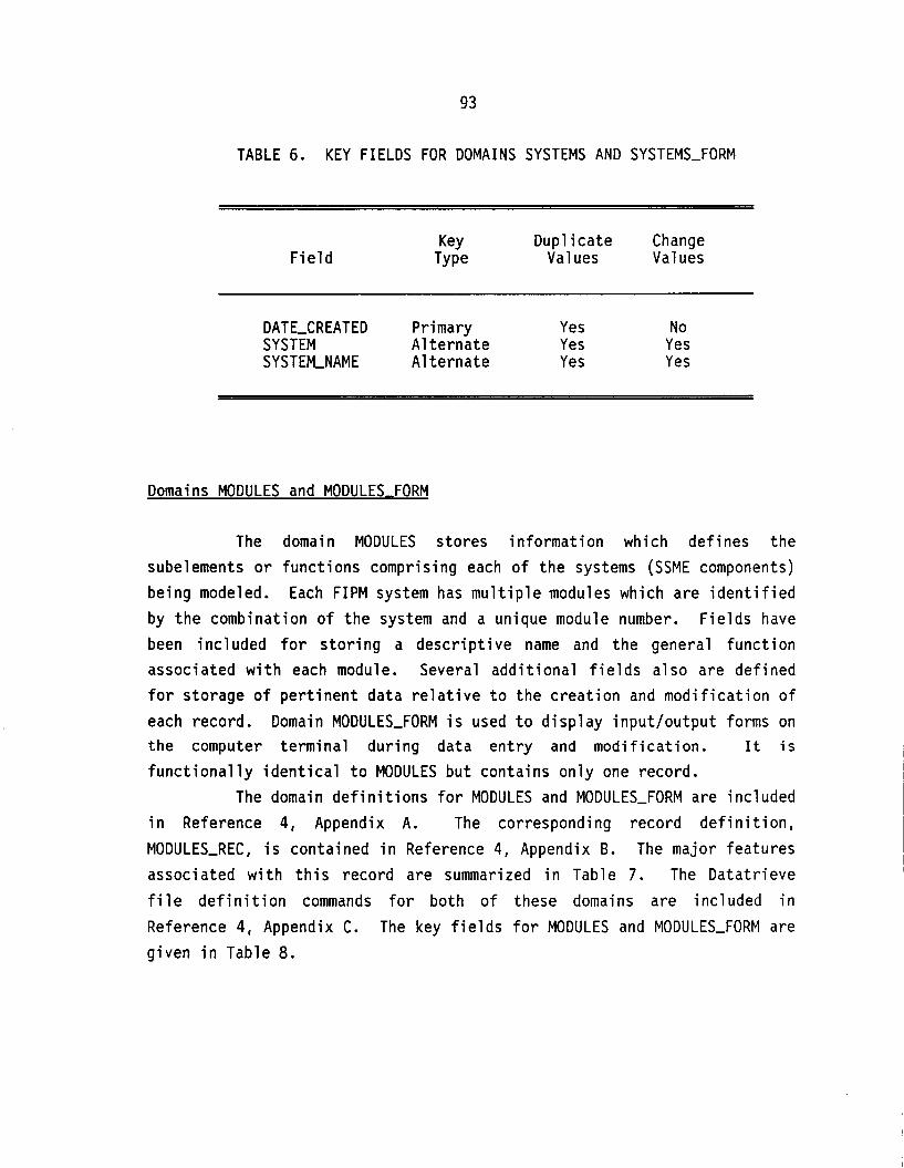
93
TABLE 6. KEY FIELDS FOR DOMAINS SYSTEMS AND SYSTEMS-FORM
Duplicate Change Values
Key Field Type Values
DATE-CREATED Primary Yes No SYSTEM A1 ternate Yes Yes SYSTEKNAME A1 ternate Yes Yes
Domains MODULES and MODULES FORM
The domain MODULES stores information which defines the subelements or functions comprising each of the systems (SSME components) being modeled. Each FIPM system has multiple modules which are identified by the combination of the system and a unique module number. Fields have been included for storing a descriptive name and the general function associated with each module. Several additional fields also are defined for storage of pertinent data relative to the creation and modification of each record. the computer functionally
The in Reference MODULES-REC,
Domain MODULES-FORM is used to display input/output forms on terminal during data entry and modification. It is
dentical to MODULES but contains only one record. domain definitions for MODULES and MODULES-FORM are included 4, Appendix A. The corresponding record definition,
s contained in Reference 4, Appendix B. The major features associated with this record are summarized in Table 7. The Datatrieve file definition commands for both of these domains are included in Reference 4, Appendix C. The key fields for MODULES and MODULES-FORM are given in Table 8.

94
x P Y . . LL
L 0
h
w m d
ee
u u u v u v u . . . c . - . c . - . c
w w w' w' E

95
TABLE 8. KEY FIELDS FOR DOMAINS MODULES AND MODULES-FORM
F i e l d Key Dup l ica te Change
Type Values Values
DATE-CREATED Primary Yes No SYSTEM-MODULE A1 te rna te Yes Yes SYSTEM-MODULE-NAME A1 te rna te Yes Yes
Domains FA1 LUREMODES and FAILUREMODES-FORM
The domain FAILUREMODES stores in fo rmat ion which def ines the f a i l u r e modes i d e n t i f i e d f o r each module. The i n d i v i d u a l modules, i n general , w i l l have m u l t i p l e f a i l u r e modes. The p r i n c i p a l f i e l d f o r each record i s a 20-character code which s p e c i f i e s t h e source module, t he f a i l u r e mechanism, and any accomplice module which may be involved. F ie lds a re prov ided f o r t h e en t r y o f t e x t which descr ibes t h e f a i l u r e mode and i d e n t i f i e s t h e general e f f e c t s associated w i t h it. Several add i t i ona l f i e l d s a l so are def ined f o r storage o f p e r t i n e n t data r e l a t i v e t o the c rea t i on and mod i f i ca t i on o f each record. Domain FAILUREMODES-FORM i s
used t o d i s p l a y input /ou tpu t forms on the computer te rmina l dur ing data e n t r y and mod i f i ca t i on . It i s f u n c t i o n a l l y i d e n t i c a l t o FAILUREMODES bu t conta ins on ly one record.
The domain d e f i n i t i o n s f o r FAILUREMODES and FAILUREMODES-FORM are inc luded i n Reference 4 , Appendix A. The corresponding record d e f i n i t i o n , FAILUREMODES-REC, i s contained i n Reference 4 , Appendix B. The major fea tures associated w i t h t h i s record are summarized i n Table 9. The Da ta t r i eve f i l e d e f i n i t i o n commands f o r both o f these domains are inc luded i n Reference 4, Appendix C. The key f i e l d s f o r FAILUREMODES and
FAILUREMODES-FORM are given i n Table 10.

96
CI LL
LL 0
m W
I-
L .n- o ) - %
.n rn * U -
2 a c
2 o) .- L
u u u u u u u u u u u u u u u u u u u ._ ._ ._ .- .- .- .- .- .- ._ .- .- .- .- .- .- .- .C .-
a u, r u, c 2: a a y w
4 4 u - -
w a a - a w 3

97
TABLE 10. KEY FIELDS FOR DOMAINS FAILUREMODES AND FAILUREMODES-FORM
Key Duplicate Change Field Type Values Values
DATE-CREATED Primary Yes No FMCODE A1 ternate Yes Yes
Domains CONNECTIONS and CONNECTIONS FORM
The domain CONNECTIONS stores information which defines the physical paths which exist between modules. In general, each module will have multiple connections to the adjacent module(s). The principal field in each record is a 21-character code which specifies the two modules being connected and the exact nature of the connection. Several additional fields also are defined for storage of pertinent data relative to the creation and modification of each record. Domain CONNECTIONS-FORM is used to display input/output forms on the computer terminal during data entry and modification. It is functionally identical to CONNECTIONS but contains only one record.
The domain definitions for CONNECTIONS and CONNECTIONS-FORM are included in Reference 4, Appendix A. The corresponding record definition, CONNECTIONS-REC, is contained in Reference 4, Appendix B. The major features associated with this record are summarized in Table 11. The Datatrieve file definition commands for both o f these domains are included in Reference 4, Appendix C. The key fields for CONNECTIONS and CONNECTIONS-FORM are given in Table 12.

98
I-
n a 0 u w Qc
E w LL
LL 0
I I

99
TABLE 12. KEY FIELDS FOR DOMAINS CONNECTIONS AND CONNECTIONS-FORM
Key Dup l ica te Change F i e l d Type Values Values
DATECREATED P r i ma ry Yes No CODE-NUMBER A1 te rna te Yes Yes
Domains PROPAGATIONS. A150 throuqh PROPAGATIONS,Z910 and PROPAGATIONS FORM
The domains PROPAGATIONS-A150 through PROPAGATIONS-Z910 s t o r e t h e ac tua l f a i l u r e in fo rmat ion propagat ion data. Each o f t h e items i n domain SYSTEMS has a separate propagations domain. One o f t h e f i e l d s i d e n t i f i e s t h e module f a i l u r e mode which i n i t i a t e d t h e in fo rmat ion f low. Another f i e l d s p e c i f i e s the p a r t i c u l a r connection t o which the data has passed. Most o f t h e f i e l d s descr ibe the s p e c i f i c c h a r a c t e r i s t i c s o f the f a i l u r e s igna l . Three t e x t f i e l d s have been inc luded f o r e n t r y o f comments p e r t a i n i n g t o the f a i l u r e in fo rmat ion propagation. Three f i e l d s a l so are def ined f o r storage o f data concerning t h e c rea t i on and m o d i f i c a t i o n o f each record. Domain PROPAGATIONS-FORM i s used t o d i sp lay i npu t /ou tpu t forms on the computer terminal . It i s f u n c t i o n a l l y i d e n t i c a l t o t h e o the r propagations domains bu t conta ins on ly one record.
The domain d e f i n i t i o n s f o r a l l o f t h e cu r ren t f a i l u r e in fo rmat ion propagations domains are inc luded i n Reference 4, Appendix A. The corresponding record d e f i n i t i o n , PROPAGATIONS-REC, i s contained i n Reference 4 , Appendix B. The major features associated w i t h t h i s record are summarized i n Table 13. The Data t r ieve f i l e d e f i n i t i o n commands f o r a l l o f t he domains are inc luded i n Reference 4, Appendix C. The key
f i e l d s f o r PROPAGATIONS-A150 through PROPAGATIONS-Z910 and PROPAGATIONS-FORM are given i n Table 14.

100
L L
LL 0
v)
Q: U v) v) Q
c

101
n a w 3
c r 0 0 Y
0 w a I VI r 0 I L
n c* 0 Y a E U L
LL 0
m
W
l-l
Ln 0- "N N N
o m m Ln NN--N- W-CUN- o " $ $
0 T cu- 0 Ln \o h
a U -

102
TABLE 14. KEY FIELDS FOR DOMAINS PROPAGATIONS-A150 THROUGH PROPAGATIONS-Z910 AND PROPAGATIONS-FORM
Key Dupl i c a t e Change F i e l d TY Pe Values Values
DATE-CREATED Primary Yes No FMCODE A1 te rna te Yes Yes CODE-NUMBER A1 te rna te Yes Yes S I G N A L T Y P E A1 te rna te Yes Yes
The domain and f i l e d e f i n i t i o n commands f o r PROPAGATIONLA150 through PROPAGATIONS-Z910 d i f f e r from those used f o r t h e o the r F I P M domains. The domain and f i l e d e f i n i t i o n commands. associated w i t h PROPAGATIONSA150 are shown respec t i ve l y i n Figures 28 and 29. The domain d e f i n i t i o n uses t h e Data t r ieve l o g i c a l s PROPAGATIONS and PROPAGATIONS-FILE w h i l e t h e f i l e d e f i n i t i o n uses the l o g i c a l PROPAGATIONS. This process was se lected t o a l l ow automated d e f i n i t i o n o f a f a i l u r e in fo rmat ion
propagat ion domain and f i l e f o r each new e n t r y i n domain SYSTEMS.
FNf CREATE-LOG ( "PROPAGAT IONS" , "PROPAGATIONSJ\lSO") FNfCREATE-LOG( "PROPAGATIONS-FILE" ,
"DEVf206 : [BCDSSME2. DATA] PROPAGATIONS-AlSO. OAT") DEFINE DOMAIN PROPAGATIONS USING PROPAGATIONS-REC ON PROPAGATIONS-FILE
I
FIGURE 28. DOMAIN D E F I N I T I O N COMMANDS FOR PROPAGATIONS-A150

103
FN$CREATE-LOG ("PROPAGATIONS", "PROPAGATIONS-A150") DEFINE FILE FOR PROPAGATIONS KEY = DATE-CREATED (DUP),
KEY = CODE-NUMBER (DUP) , KEY = SIGNAL-TYPE (DUP)
KEY = FMCODE (DUP) 1
FIGURE 29. FILE DEFINITION COMMANDS FOR PROPAGATIONS-A150
Domains REFERENCES and REFERENCES FORM
The domain REFERENCES stores in fo rmat ion on t h e var ious documents used dur ing the fo rmula t ion o f t he FIPMs. The f i e l d s i n t h i s record prov ide f o r t h e i n p u t o f standard b i b l i o g r a p h i c a l in fo rmat ion such as author(s) , t i t l e , company, company document number, data, and con t rac t number. Another f i e l d s to res a unique reference number f o r t he document which i s assigned by t h e Data t r ieve i n p u t procedure. Several add i t i ona l f i e l d s a l s o are def ined f o r storage o f p e r t i n e n t data r e l a t i v e t o the c r e a t i o n and mod i f i ca t i on o f each record. Domain REFERENCES-FORM i s used t o d i s p l a y input /ou tpu t forms on the computer te rmina l dur ing data en t r y and mod i f i ca t i on . It i s f u n c t i o n a l l y i d e n t i c a l t o REFERENCES but contains
on ly one record. The domain d e f i n i t i o n s f o r REFERENCES and REFERENCES-FORM are
inc luded i n Reference 4, Appendix A. The corresponding record d e f i n i t i o n ,
REFERENCES-REC, i s contained i n Reference 4, Appendix B. The major fea tures associated w i t h t h i s record are summarized i n Table 15. The Da ta t r i eve f i l e d e f i n i t i o n commands f o r both o f these domains are inc luded i n Reference 4, Appendix C. The key f i e l d s f o r REFERENCES and REFERENCES-FORM are given i n Table 16.

104
LL W a
0 w a
v u .- .- L L U U
c c a m c a J c 14 Q - a- S J
u a u
v v v v v v v u u u v v u .- . - . - . C . - . C . C . C . C . C . C .C.C
L L L L L L L L L L L L L

105
TABLE 16. KEY FIELDS FOR DOMAINS REFERENCES AND REFERENCES-FORM
F i e l d Key Dup l ica te Change
TY Pe Values Values
DATE-CREATED Primary Yes No REFERENCLNUMBER A1 te rna te Yes Yes DOCUMENT-TITLE A1 te rna te Yes Yes DOCUMENT-SOURCE A1 te rna te Yes Yes

106
(This page intentionally blank)

107
FIPM DATA BASE SOFTWARE
The FIPM data base development software provides a controlled, interactive environment in which failure information propagation data can be stored, modified, and listed. The software allows the user to perform a number of predefined data base operations. Direct access to the data base is restricted to prevent inadvertent changes which can invalidate large portions of the data files. The software also performs an extensive number of validation tests on the information entered by the user during the storage and modification of FIPM records. The data base software was developed using the following three Digital Equipment Corporation (DEC) software packages:
VAX/VMS Digital Command Language (DCL)
Datatrieve
Terminal Data Management System (TDMS).
DCL command procedures provide the overall control of the FIPM software through a series of four menus. VAX command files 'containing Datatrieve instructions are used in conjunction with the menus to initiate the storage, modification, or listing o f FIPM information. The actual manipulation of the FIPM records is accomplished using Datatrieve procedures and tables. Terminal forms created using TDMS utilities provide the interactive user interface. The DCL, Datatrieve, and TDMS software elements are outlined in the following subsections.
Diqi tal Command Lanquaqe Procedures
The Digital Command Language enables the user to instruct the VAX/VMS operating system to perform various operations. DCL command procedures are files which contain a series of DCL commands. When a command procedure is executed, the computer processes a1 1 of the commands contained in the file and then returns to the point of origin. DCL command procedures are used in the FIPM data base to provide the top- level control of the software elements.

108
When a user i n i t i a t e s a VAX computer session, t he operat ing system searches t h e d e f a u l t f i l e d i r e c t o r y f o r a f i l e named LOGIN.COM. I f the f i l e i s found, t h e computer executes the DCL commands i n LOGIN.COM before per forming any o the r operat ions. The FIPM data base development sof tware uses t h i s i n t r i n s i c VAX process t o d i r e c t t he program f l o w i n t o a c a r e f u l l y c o n t r o l l e d environment. The user i s channeled from one procedure t o t h e nex t w i thout going t o t h e DCL command l e v e l . Prov is ions are incorporated f o r users w i t h specia l access p r i v i l e g e s t o bypass these procedures and execute commands a t the DCL l e v e l .
The LOGIN.COM f i l e created f o r t he FIPM data base pauses f o r a response from t h e te rmina l . I f the user enters t h e c o r r e c t access code, the procedure w i l l prompt f o r PASSWORD 1 procedure e x i t s t o t h e DCL command l e v e l passwords are entered c o r r e c t l y . I f e i t h e r no t v a l i d , t h e procedure loops back t o the A l l responses except f o r t he co r rec t acce
and then PASSWORD 2. The f the access code and both PASSWORD 1 o r PASSWORD 2 i s p o i n t o f t he i n i t i a l pause. s code w i l l r e s u l t i n the
computer execut ing the DCL procedure FIPFLMENU.COM. FIPM-MENU.COM d isp lays the main FIPM menu t o the user. This menu i s shown i n F igure 30. The program f l o w i s d i r e c t e d t o e i t h e r FIPM_STORE.COM, FIPM_MODIFY.COM, o r FIPFLLIST.COM depending on t he l i n e number se lected (1, 2, o r 3 respec t i ve l y ) . The user can a l so terminate the cu r ren t computer session by en te r ing l i n e number 4. It i s poss ib le t o e x i t t o t h e DCL command l e v e l f rom t h e main menu by en te r ing the c o r r e c t access code and passwords. The top - leve l FIPM software f l o w i s depic ted i n F i g u r e 31.
L i s t i n g s o f t h e DCL procedures LOGIN.COM and FIPlotMENU.COM are inc luded i n Reference 4, Appendix D.

109
MAIN MENU
1. S t o r e FIPM Data 2. M o d i f y FIPM Data 3. L i s t FIPM Data 4. E x i t Procedure and Logout
P lease e n t e r LINE NUMBER:
F IGURE 30. MENU FOR CONTROLLED ACCESS TO F I P M DATA BASE
LOGIN. COM
F I PM-MENU. COM
F I PM-STORE . COM
F I PM-MOD I FY . COM
F I PM-LI ST. COM
Terminate Session
VAX DCL Comnand Level
Invoke D a t a t r i e v e
Invoke TDMS U t i l i t i e s
Execute DCL Comnands
Terminate Session
F IGURE 31. TOP-LEVEL F I P M SOFTWARE FLOWS
110
I f t h e user se lec ts the s to re F I P M data op t ion , t he DCL procedure FIPM_STORE.COM i s c a l l e d t o d i sp lay t h e menu shown i n F igure 32. A response o f 1 through 6 w i l l r e s u l t i n the execut ion o f t h e Data t r ieve command f i l e STORE-REF.COM, STORE,SYS.COM, STORE-MOD.COM, STORE-FM.COM,
STORE-CON.COM, o r S T O R L F I P . C O M respec t ive ly . A f t e r execut ing the appropr ia te Da ta t r i eve command f i l e , t he procedure FIPM_STORE.COM red isp lays t h e s t o r e menu. The user may e l e c t t o cont inue s t o r i n g data i n any o f t h e d isp layed domains o r may r e t u r n t o the main menu procedure by s e l e c t i n g l i n e number 7 . The program f l o w f o r s t o r i n g F IPM data i s shown i n F igure 33. A l i s t i n g o f t he DCL command procedure FIPM_STORE.COM i s inc luded i n Reference 4, Appendix D.
I f t h e user se lec ts the modify F IPM data opt ion, t h e DCL procedure FIPM-MODIFY.COM i s c a l l e d t o d i sp lay t h e menu shown i n F igure 34. A response o f 1 through 5 w i l l r e s u l t i n t h e execut ion o f t he Da ta t r i eve command f i l e MODIFY-REF.COM, MODIFY-SYS.COM, MODIFY-MOD.COM, MODIFY,FM.COM, o r MODIFY-FIP.COM respec t ive ly . The records i n domain CONNECTIONS cannot be mod i f ied from t h i s menu. A f t e r execut ing the appropr ia te Data t r ieve command f i l e , t he procedure FIPM-MODIFY.COM red isp lays t h e modi fy menu. The user may e l e c t t o cont inue modi fy ing data i n any o f t h e d isp layed domains o r may r e t u r n t o the main menu procedure by s e l e c t i n g l i n e number 6. The program f l ow f o r modi fy ing F I P M data i s shown i n F igure 35. A l i s t i n g o f t he DCL command procedure FIPM_MODIFY.COM i s inc luded i n Reference 4, Appendix D.

111
FIPM-STORE.COM (DCL) 4
STORE-REF . COM (DTR) .)
w STORE-SYS .COM (DTR) w
t STORE-MOD . COM (DTR) h
t STORE-FM. COM (DTR) D
> STORE-CON. COM (DTR) w
* STORE-FI P. COM (DTR)
aaIIIIIIIIaIaIIIaIIaaIIaIaaaIIIaaa~aaIaIaaaxaIx
FAILURE INFORMATION PROPAGATION MODEL
STORE MENU
1. D o m a i n REFERENCES 2. D o m a i n SYSTEMS 3. D o m a i n MODULES 4 . D o m a i n FAILUREMODES 5. Domain CONNECTIONS 6. D o m a i n PROPAGATIONS 7. E x i t t o MAIN MENU
P l e a s e enter L I N E NUMBER:
F I G U R E 32. MENU FOR STORING F I P M DATA BASE RECORDS
F I G U R E 33. PROGRAM FLOW FOR STORING F I P M DATA

112
* MODI FY-REF . COM (DTR) w
w MOD I FY-SY S . COM (DTR) *
* MODI FY-MOD. COM (DTR) *
w MODI FY-FM. COM (DTR) *
* MODIFY-FIP.COM (DTR)
MODIFY MENU
1. Domain REFERENCES 2. Domain SYSTEMS 3. Domain MODULES 4. Domain FAILUREMODES 5 . Domain PROPAGATIONS 6. E x i t t o MAIN MENU
P l e a s e enter L I N E NUMBER:
FIGURE 34. MENU FOR MODIFYING F I P M DATA BASE RECORDS
FIPM-MENU.COM (DCL) 4 I
FIGURE 35. PROGRAM FLOW FOR MODIFYING F I P M DATA

113
If the user selects the list FIPM data option, the DCL procedure FIPM-LIST.COM is called to display the menu shown in Figure 36 . A response of 1 through 6 will result in the execution of the Datatrieve command file LIST-REF-l.COM, LIST-SYS-l.COM, LIST-MOD-l.COM, LIST-FM_l.COM, LIST-CON,l.COM, or LIST-FIP-1.COM respectively. After executing the appropriate Datatrieve command file, the procedure FIPM-LIST.COM requests a yes or no response to list the records in the domain. A response of yes results in a batch job being submitted to generate the listing. A
no response causes the immediate redisplay of the list menu. The user may elect t o continue listing data for any of the displayed domains or may return to the main menu by selecting line number 7 . The program flow for listing FIPM data is shown in Figure 37 . A listing of the DCL command procedure FIPM_LIST.COM is included in Reference 4 , Appendix D.
The procedure then loops back to the list menu.
FAILURE INFORMATION PROPAGATION MODEL
L I S T MENU
1. Domain REFERENCES 2. Domain SYSTEMS 3 . Domain MODULES 4. Domain FAILUREMODES 5. Domain CONNECTIONS 6 . Domain PROPAGATIONS 7 . Exit to MAIN MENU
Please enter LINE NUMBER:
FIGURE 36 . MENU FOR LISTING FIPM DATA BASE RECORDS
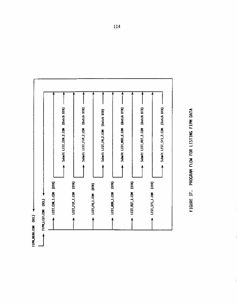
114
r
s c!
d
4
n
c
c V 4 a
a n
m - 5 u N
d LL
c
d
Y
P
v)
I
‘c
c
a
f
4 A A
I,
CI a c 0
c V Y a m u
6 c! 2 3 z -I
Y
3 a v)
n
0
c V Y a m
P
Y
s u Yl cl
N
W m
v)
-1
Y
E a a v)
- c
f h m

115
Data t r i eve Command F i l e s . Procedures, and Tables
The ac tua l storage, mod i f i ca t i on , and l i s t i n g o f FIPM in fo rma t ion i s performed us ing Da ta t r i eve command f i l e s and procedures. Da ta t r i eve command f i l e s a re VAX system-level f i l e s which con ta in a se r ies o f Da ta t r i eve commands and statements. These f i l e s a re invoked from i n s i d e Da ta t r i eve t o perform t h e desired operations. Da ta t r i eve procedures a l s o conta in a se r ies o f Data t r ieve commands and statements. However, these procedures are s to red i n t h e VAX Common Data D ic t i ona ry (CDD). The CDD i s used by Da ta t r i eve t o s t o r e and access t h e var ious elements associated w i t h t h e data base.
The Da ta t r i eve command f i l e s and procedures developed f o r t h e FIPM data base use Da ta t r i eve tab les t o v a l i d a t e and supplement i n fo rma t ion be ing entered. An example o f a Da ta t r i eve t a b l e i s shown i n F igure 38. These tab les are used t o v a l i d a t e data by accept ing on ly values which a re i n t h e tab le . They a l so prov ide a d d i t i o n a l da ta through t r a n s l a t i o n o f t h e value on t h e l e f t -hand s ide o f t h e co lon i n t o t h e value on t h e r igh t -hand side. This l a t t e r f unc t i on was e s p e c i a l l y use fu l f o r c r e a t i n g abbrev ia t ions t o represent key FIPM data. The o v e r a l l record s i z e was reduced by s t o r i n g t h e abbrev ia t ion r a t h e r than t h e e n t i r e value.
DEFINE TABLE REFERENCE-ABBREV-TABLE 1
: IIAJ" : IIBA"
"AEROJET" " BATTELLE" "MARTIN MARIETTA" : I'MM" "NASA HDQ" "NASA MSFC" "PRATT & WHITNEY" : "PW"
: IINH" : IlNMIl
"ROCKETDYNE" : IlRDIl 1
EN D-TAB LE
FIGURE 38. SAMPLE DATATRIEVE TABLE

116
The Datatrieve command f i l e s , procedures, and tables used t o s tore FIPM information are shown in Figure 39. The command f i l e s STORE-REF. COM , STORE-SYS . COM, STORE-MOD . COM , STORE-FM. COM , STORE-CON . COM , and STORE-FIP.COM are executed by the DCL command procedure FIPM,STORE.COM (s tore menu). Each of these Datatrieve command f i l e s opens a log f i l e t o document the records being stored i n the corresponding domain, prints the current date/time t o the log f i l e and then invokes the appropriate Datatrieve procedure(s). After completion of the storage ac t iv i ty , the program flow i s returned t o the command f i l e where the current date/time i s again printed before closing the log f i l e . Execution i s then returned t o the DCL procedure FIPM-STORE.COM for redisplay of the s tore menu. The Datatrieve command f i l e s , procedures, and tables used t o s tore FIPM data are included i n Appendixes E , F, and G of Reference 4.
The Datatrieve command f i l e s , procedures, and tables used t o modify FIPM information are shown in Figure 40. The command f i l e s MODIFY-REF.COM, MODIFY-SYS.COM, MODIFY-MOD.COM, MODIFY-FM.COM, and MODIFY-FIP.COM are executed by the DCL command procedure FIPM-MODIFY.COM (modify menu). Each of these Datatrieve command f i l e s opens a log f i l e t o document the records being modified in the corresponding domain, prints the current date/time t o the log f i l e and then invokes the appropriate Datatrieve procedure(s). After completion of the modification ac t iv i ty , the program flow i s returned t o the command f i l e where the current date/time i s again printed before closing the log f i l e . Execution i s then returned t o the DCL procedure FIPM-MODIFY.COM for redisplay of the modify menu. The Datatrieve command f i l e s , procedures, and tables used t o modify FIPM data are included in Appendixes E , F, and G of Reference 4.

1 1 7
Command F i 1 es :
STORLCON.COM STORE-FIP.COM S T O R L F M . COM STORLMOD. COM S T O R L R E F . COM STORE-FIP.COM
P r o c e d u r e s :
BELL CLRSCRN CON-STORE CREATLPROPAGAT I ONS-F I P-1 CREATLPROPAGATIONS-FIP-2 CREATE-PROPAGATIONS-SYS-1 CREATE-PROPAGATIONS-SYS-2 D T R N U L L FIP-STORE F I P-STORE-1 F I P-STORE-2 F K S T O R E MOD-STOR E REF-STORE SY S-STORE
T a b l e s :
ACCOMPLICLREQUIRED-TABLE CONNECTION-TABLE FAILURLMODLSUBMODE-TABLE FMEA-ITEM-NAME-TABLE FREQ-T I M L U N I TS-TABLE MONTH-TABLE PARAMETERTABLE REFERENCE-ABBREV-TABLE REFERENCE-SOURCE-TABLE SIGNAL-TABLE
FIGURE 39. DATATRIEVE COMMAND F I L E S , PROCEDURES AND TABLES USED TO STORE F I P M DATA

118
Command Files:
MODIFY-FIP.COM MODIFY-FM.COM MODIFYJIOD.COM MODIFY,REF.COM MOD I FY-SY S . COM
Procedures :
BELL CLRSCRN DTRNULL FI PJIOD I FY FIP-MODIFY-1 FIP-MODIFY-2 F I P-MOD I FY-3 FIP-MODIFY-4 F K M O D I FY FM-MODIFY-1 MOD-MOD I FY MODJIODI FY-1 REF-MODIFY REF-MODI FY-1 SY S-MOD I FY SYS-MODI FY-1 SYSJIODIFY-2
Tables:
FAILURE-MODE-SUBMODE-TABLE FMELITEM-NAME-TABLE MONTH-TABLE NUMBERTABLE PARAMETERTABLE REFERENCLSOURCE-TABLE SIGNALTABLE SIGN-TABLE
FIGURE 40. DATATRIEVE COMMAND FILES, PROCEDURES AND TABLES USED TO MODIFY FIPM DATA

119
The Data t r ieve command f i l e s , procedures, and tab les used t o l i s t F IPM in fo rmat ion are shown i n F igure 41. The command f i l e s LIST-REF-l.COM, LIST-SYS,l.COM, LIST-MOL1 .COM, LIST-FKl.COM, LIST-CON-l.COM, and LIST-FIP-1.COM are executed by t h e DCL command procedure FIPlrtLIST.COM ( l i s t menu). Each o f these Data t r ieve command f i l e s counts t h e number o f records i n the corresponding domain and ca l cu la tes t h e number o f pages i n the l i s t f i l e . Th is in fo rmat ion i s p r i n t e d t o t h e screen and program execut ion re tu rns t o FIPM-LIST.COM. I f an ac tua l l i s t i n g i s desired, t h e appropr ia te Data t r ieve command f i l e LIST,REF,2.COM, L I ST-SY S-2. COM, LIST,MOD,2.COM, LIST-FM2.COM, LIST-CON-2.COM, o r LIST-FIP,Z.COM i s submitted as a batch job t o generate t h e l i s t f i l e . Execution o f t h e DCL procedure FIPM_LIST.COM then cont inues w i t h red i sp lay o f t he l i s t menu. The Data t r ieve command f i l e s , procedures, and tab les used t o l i s t FIPM data are inc luded i n Appendixes
E, F, and G o f Reference 4. A number o f Data t r ieve procedures were used dur ing the F I P M data
base sof tware development t o simp1 i f y c e r t a i n funct ions. As examples, t he procedure CREATLCONNECTIONS executes t h e f i l e d e f i n i t i o n command f o r domain CONNECTIONS and the procedure S132 sets t h e te rmina l screen w id th t o 132 characters . I n add i t i on t o these procedures, t h e Data t r ieve t a b l e FMELITElrtPART-NO-TABLE was created t o p rov ide the Rocketdyne p a r t numbers (Reference 3, Table 2-1) associated w i t h s p e c i f i c FMEA items. These
procedures and t a b l e a re shown i n F igure 42. L i s t i n g s f o r t h e procedures are inc luded i n Reference 4, Appendix F and the t a b l e i s inc luded i n Reference 4 , Appendix G.
I

120
Comand F i l e s :
LIST-CON-1. COM L I S T CON 2.COM
LIST-FIP 2.COM L I S T FM T.COM L I STIFM-2. COM LIST MOB-l.COM LISTIMOD-2. COM L I ST-REF 1 . COM LIST-REF-2. COM LIST SYS-1.COM L I STISY S I2 . COM
LIST:FIP:~.COM
Procedures :
C L R S C R N DTR NULL FIPICOUNT FIP COUNT-1
FIP LIST-2
F I P-L I S T I 4
FIP-COUNT 2 FI P ~ L I ST-T
FIP~LIST 3
FIGURE 41. DATATRIEVE COMMAND F I L E S AND PROCEDURES USED TO L I S T F I P M DATA
Procedures :
CREATE-CONNECTIONS CREATE CONNECTIONS FORM
CREATE-FA1 LUREMODES-FORM
CREATE MODULES FORM
CREATE-FAILUREMODES CREATE~MODULES
CREATE-PROPAGATIONS CREATE-PROPAGATIONS-FORM CREATE-REFERENCES CREATE-REFERENCES-FORM CREATE~SY STEMS
FIPLOGTCALC CREATE SYSTEMS-FORM
F I PLOGICALD HDR PRNTOFF PRNTON 5132 580
Tab les :
FMEA-ITEM-PART-NO-TABLE
F IGURE 42. MISCELLANEOUS DATATRIEVE PROCEDURES AND TABLES USED FOR F I P M

121
Terminal Data Manaqement Svstem Forms
Two TDMS u t i l i t i e s were used t o c rea te and compile terminal forms f o r use w i t h t h e FIPM data base. These forms prov ide the i n t e r a c t i v e i n t e r f a c e between the data base user and the under ly ing software. The s p e c i f i c u t i l i t i e s used were t h e Form D e f i n i t i o n U t i l i t y (FDU) and t h e Request D e f i n i t i o n U t i l i t y (RDU). FDU was used t o c rea te t h e screen image, de f i ne t h e v ideo features, assign a t t r i b u t e s t o the var ious i n p u t f i e l d s , es tab l i sh t h e f i e l d access order , and save the completed form i n t h e Common Data D ic t i ona ry (CDD). The FIPM form d e f i n i t i o n s are inc luded i n Reference 4, Appendix H. The RDU was used t o c rea te a request l i b r a r y which i d e n t i f i e s a l l o f t he F IPM forms. The VAX
computer f i l e associated w i t h the compiled forms i s a l so s p e c i f i e d i n the request l i b r a r y d e f i n i t i o n . F i n a l l y , RDU i s used t o b u i l d (compile) t he request l i b r a r y and c rea te the l i b r a r y f i l e i d e n t i f i e d i n the d e f i n i t i o n . The FIPM request l i b r a r y d e f i n i t i o n i s shown i n F igure 43.
FORM I S CONNECTIONS-STO-FORM; FORM I S FA1 LUREMODES-FINLFORM; FORM IS FAILUREMODES-FIN2-FORM; FORM I S FAILUREMODES-MODLFORM; FORM IS FA1 LUREMODES-MOD2-FORM; FORM I S FA1 LUREMODES-STOLFORM; FORM IS FAILUREMODES-ST02-FORM; FORM I S MODULES-FIN-FORM; FORM I S MODULESJOD-FORM; FORM I S MODULES-STO-FORM; FORM I S PROPAGATIONS-FIN-FORM; FORM I S PROPAGATIONS-MOD-FORM; FORM I S PROPAGATIONS-STO-FORM; FORM IS REFERENCES-FIN-FORM; FORM IS REFERENCES-MOD-FORM; FORM I S REFERENCES-STO-FORM; FORM I S SYSTEMS-FIN-FORM; FORM I S SYSTEMS-MOD-FORM; FORM I S SYSTEMS-STO-FORM; FILE I S "DEV$206: [BCDSSME2.FORMS] FORMSLIB.RLB";
END DEFINIT ION;
FIGURE 43. F I P M REQUEST LIBRARY DEFINIT ION

122
(This page intentionally blank)

123
FIPM DATA BASE TRANSFER
A magnetic tape conta in ing the FIPM data base development sof tware and t h e high-pressure o x i d i z e r turbopump (HPOTP) data f i l e s was mai led t o t h e NASA Marshal l Space F l i g h t Center i n February 1987. This tape was w r i t t e n us ing the VAX/VMS Backup U t i l i t y and contained m u l t i p l e copies o f 60 f i l e s . These f i l e s are shown i n F igure 44. The f i l e ACTIVATE.COM was a DCL command procedure developed t o load and organize a l l o f t h e requ i red FIPM s t r u c t u r e i n t o a newly es tab l i shed VAX username. The 19 f i l e s o f t he type *.DAT a re the data f i l e s associated w i t h the HPOTP FIPM. The 28 f i l e s o f t he types FIPK*.COM, LIST-*.COM, LOGIN.COM, MODIFY-*.COM, and STORL*.COM are the DCL command procedures and Da ta t r i eve command f i l e s discussed i n the prev ious sect ion. The th ree f i l e s o f t h e type CDD-FORMS,*.BAK conta in the compiled form d e f i n i t i o n s as ex t rac ted from the CDD. The n ine f i l e s o f t h e type DTR-*.COM conta in the Da ta t r i eve domain, record, procedure, and t a b l e d e f i n i t i o n s .
ACTIVATE.COM CDD-FORMS-3.BAK DTRDOMAI NS . COM DTRPROCS-3.COM DTRPROCS-6. COM FA1 LUREMODES. DAT FIPM_MENU.COM LIST-CON-1.COM LIST-FIP-2.COM LIST-MOD,l.COM LIST-REF-2.COM LOG I N . COM MODIFY,MOD.COM MODULES.DAT PROPAGATIONS-A200.DAT PROPAGATIONS-B400.DAT PROPAGATIONS,FORM.DAT REFERENCES-FORM.DAT STORE-FM.COM STORE,SYS.COM
CDD-FORMS-1. BAK CONNECTIONS.DAT DTRPROCS-l.COM DTRPROCS-4. COM DTRRECORDS . COM FA1 LUREMODES-FORM. DAT FIPKMODIFY.COM LIST-CON-2.COM LIST-FM-1.COM LIST-MOD-2.COM LIST-SYS-1.COM MODIFY,FIP.COM MODIFY-REF.COM MODULES-FORM.DAT PROPAGATIONS-A600. DAT PROPAGATIONS-B800. DAT PROPAGATIONS-Z910.DAT STORLCON.COM STOREJIOD.COM SYSTEMS.DAT
Tota l o f 60 f i l e s .
CDD-FORMS-2.BAK CONNECTIONS,FORM.DAT DTR-PROCS-2.COM DTR-PROCS-5.COM DTRTABLES.COM F I PM-LIST. COM FIPM-STORE.COM LIST-FIP-1.COM LIST-FM-2.COM LIST-REF-1.COM LIST-SYS-2.COM MODIFY-FM.COM MODIFY-SYS.COM PROPAGATIONS-A15O.DAT PROPAGATIONS-A700.DAT PROPAGATIONS-C200.DAT REFERENCES.DAT STORE-FIP.COM STORE-REF.COM SYSTEMS-FORM.DAT
FIGURE 44. VAX/VMS FILES USED TO TRANSFER F I P M DATA BASE
124
The procedure ACTIVATE.COM created t h e necessary VAX/VMS
d i r e c t o r y s t r u c t u r e , created a Data t r ieve d i c t i o n a r y , loaded a l l o f t he Data t r ieve elements (domains, records, procedures, and tab les) def ined a TDMS request l i b r a r y and b u i l t t he TDMS request l i b r a r y f i l e . A l i s t i n g o f t h e f i l e ACTIVATE.COM i s inc luded i n Reference 4 , Appendix D. The r e s u l t i n g VAX d i r e c t o r y s t r u c t u r e i s shown i n F igure 45. The top- leve l d i r e c t o r y , [BCDSSME2], conta ins the o ther d i r e c t o r y f i l e s , t he Data t r ieve d i c t i o n a r y f i l e , and two DCL command procedures. The f i l e s contained i n t h i s d i r e c t o r y a re shown i n F igure 46. The d i r e c t o r y [BCDSSMEZ.DATA] conta ins t h e FIPM data f i l e s as shown i n F igure 47. The d i r e c t o r y [BCDSSME2.DTR] i s used as a ho ld ing area f o r t h e command f i l e s conta in ing t h e Da ta t r i eve domain, record, procedure, and t a b l e d e f i n i t i o n s . The f i l e s i n t h i s d i r e c t o r y are shown i n F igure 48. The d i r e c t o r y [BCDSSME2. FIPM] conta ins t h e DCL command procedures and Data t r ieve command
f i l e s which d i s p l a y the FIPM menus and i n t e r a c t w i t h the data base. These f i l e s a re shown i n F igure 49. The d i r e c t o r y [BCDSSMEZ.FORMS] conta ins the compiled form d e f i n i t i o n f i l e s and the request l i b r a r y f i l e as shown i n F igure 50. The d i r e c t o r i e s [BCDSSME2. LISTS], [BCDSSMEZ.LOGS] I and [BCDSSMEZ.MISC] a re i n i t i a l l y empty. Any F IPM l i s t i n g f i l e s generated by t h e FIPM sof tware w i l l be w r i t t e n t o the [BCDSSMEZ.LISTS] d i r e c t o r y . The l o g f i l e s which are created as FIPM records are s to red o r mod i f ied are
w r i t t e n t o t h e d i r e c t o r y [BCDSSME2.LOGS]. The f i n a l d i r e c t o r y , [BCDSSMEZ.MISC], was inc luded f o r miscellaneous f i l e s which may be created by t h e user.

Level 1
Level 2
Level 2
Level 2
Level 2
Level 2
Level 2
Level 2
F IGURE 45. F I P M DIRECTORY STRUCTURE

126
ACTIVATE.COM DATA.DIR DTR.DIR F I PM . D I R FORMS. D I R L I S T S . D I R LOG1 N . COM LOGS. D I R MISC.DIR SSME. D I C
T o t a l of 10 files.
FIGURE 46. DIRECTORY DEV$206: [BCDSSME2]
CONNECTIONS.DAT CONNECT I ONS-FORM . D AT FAILUREMODES. DAT F A 1 LUREMODELFORM. DAT MODULES.DAT MODULES,FORM.DAT PROPAGATIONS-A150.DAT PROPAGATIONS4200.DAT PROPAGATIONS-A600. DAT PROPAGATIONS-A700. DAT PROPAGATIONS-B400.DAT PROPAGATIONS-B800.DAT PROPAGATIONS-C200.DAT PROPAGATIONS-FORM.DAT PROPAGATIONS-Z910.DAT REFERENCES.DAT REFERENCES,FORM.DAT SYSTEMS.DAT SYSTEMS-FORM.DAT
T o t a l of 19 files.
FIGURE 47. DIRECTORY DEV$206: rBCDSSME2. DATA]

127
DTRDOMAINS.COM DTRPROCS-1. COM DTRPROCS-2. COM DTRPROCS-3. COM DTRPROCS-4.COM DTRPROCS-5.COM DTRPROCS-6. COM DTRRECORDS.COM D T R T A B L E S . COM
T o t a l o f 9 f i l e s .
FIGURE 48. DIRECTORY DEV$206 : [ BCDSSME2 . DTR]
FIPM-LIST.COM FIPM-MENU.COM FIPM_MODIFY.COM F I PM-STORE. COM LIST-CON-1.COM LIST-CON-2.COM LIST-FIP- l .COM LIST-FIP-2.COM LIST-FM-1.COM LIST-FM-2.COM LISTJIOD-1.COM LIST-REF-1 .COM LIST-SYS-1 .COM MODIFY,FIP.COM MODIFY,MOD.COM MODIFY,SYS.COM STORE-FIP.COM STORLMOD. COM STORE-SYS . COM
L I ST-MOD-2. COM LIST-REF-2.COM LIST-SYS-2.COM MODIFY,FM.COM MODIFY-REF.COM STORE-CON. COM STORE-FM.COM S T O R L R E F . COM
T o t a l o f 27 f i l e s .
F IGURE 49. DIRECTORY DEV6206: [BCDSSMEZ. F I P M ]
CDD-FORMS-1.BAK CDD-FORMS,Z.BAK CDD-FORMS-3.BAK FORMSLIB.RLB
T o t a l o f 4 f i l e s .
F IGURE 50. DIRECTORY DEV$206: [BCDSSMEZ. FORMS]

128
(This page intentionally blank)
129
HIGH-PRESSURE OXIDIZER TURBOPUMP FIPM
The first SSME component analyzed using the failure information propagation model (FIPM) was the high-pressure oxidizer turbopump (HPOTP) . One of the reasons for selecting the HPOTP was the relatively high number of unsatisfactory condition reports (UCRs) associated with this component. The HPOTP also received a very high score in the failure mode ranking which considered the cost, risk, and time factors connected with various component failure modes. A major area of concern for the HPOTP is ball bearing wear and cage delamination. Another item which has received considerable attention is cracking of the hot-gas turbine blades. Both of these areas have been the focus of extensive efforts by NASA and Rocketdyne to identify and diagnose degradation of the respective parts. All of these factors made the HPOTP an attractive candidate for the initial FIPM.
following items: The HPOTP failure information propagation model consists of the
HPOTP FIPM drawing HPOTP data stored in the FIPM data base.
Specific details concerning each of these elements are provided later in this section.
Definition o f Hiqh-Pressure Oxidizer TurboDurne
The high-pressure oxidizer turbopump is designated in the FIPM The failure information propagation model f o r data base as System 8400.
this system includes the following Rocketdyne FMEA items:
High-pressure oxidizer turbopump (8400) Low-pressure oxidizer turbopump turbine drive duct (K202)
High-pressure oxidizer duct (K205) Fuel preburner oxidizer supply duct (K206) Preburner pump inlet duct (K208) Oxidizer preburner oxidizer supply duct (K212).

130
References 3, 5, and 6 of this report were the principal sources used during the preparation of this FIPM.
Hiqh-Pressure Oxidizer Turbopump FIPM Drawinq
The HPOTP FIPM drawing is included in Appendix B of this report. The drawing for the HPOTP (System B400) includes the following features:
105 modules 198 connections 260 failure modes.
8 systems (B400 plus 7 adjacent)
The actual HPOTP, including associated engine items such as ducts and lines, is depicted by 90 modules (boxes). The remaining 15 modules are piece-parts or functions of adjacent engine systems such as System A150 (heat exchanger). The modules which are not part of the HPOTP are easily identified by the diagonal lines in the lower portion of the box. Of the 198 connections (lines) shown on the diagram, 29 represent physical paths to the various external systems. The remaining 169 connections are internal to the HPOTP.
Hiqh-Pressure Oxidizer Turbopump FIPM Data
The information which collectively defines the HPOTP FIPM is stored in a total of six domains. The domains which contain HPOTP FIPM information include:
SYSTEMS MODULES FAILUREMODES (failure modes) CONNECTIONS PROPAGATIONS,B400 (failure information propagations) REFERENCES.

13 1
The key r e l a t i o n s h i p s between records i n t h e var ious FIPM domains are
i l l u s t r a t e d i n F igure 51. The domains SYSTEMS, MODULES, FAILUREMODES, CONNECTIONS, and REFERENCES s to re records f o r a l l o f t h e var ious engine components (systems) being modeled. The domain PROPAGATIONS-B400 inc ludes f a i l u r e in fo rmat ion propagations on ly f o r t he HPOTP (System B400). D e t a i l s concerning t h e data content and number o f HPOTP records f o r each o f these domains o r f i l e s are provided i n the f o l l o w i n g subsections o f t h i s repo r t .
Svstems Data F i l e
There are e i g h t records i n t h e domain SYSTEMS which are associated w i t h t h e HPOTP FIPM. The cu r ren t data f o r each o f these records are inc luded i n Reference 7 , Appendix B. A l l o f t h e records i n domain SYSTEMS conta in t h e 31 data f i e l d s shown i n F igure 52. The f i e l d names are shown t o the l e f t o f t he colons. The data s to red i n the f i e l d s a re found t o t h e r i g h t o f t he colons.
The DATE-CREATED, DATELAST-MODIFIED, and MODIFYING-PROCEDURE f i e l d s a re used f o r t r a c k i n g purposes. DATE-CREATED i s t h e date t h a t t he record was f i r s t s to red i n t h e data base. DATE-LAST-MODIFIED i s t h e date o f t h e most recent record mod i f i ca t ion . MODIFYING-PROCEDURE i d e n t i f i e s
t h e procedure which performed the l a s t record mod i f i ca t ion . A l l t h ree o f
these f i e l d s a re au tomat ica l l y assigned by the appropr ia te Data t r ieve e n t r y and m o d i f i c a t i o n procedures. The f i e l d SYSTEM conta ins the fou r -
charac ter code which i s used t o represent a given system. S Y S T E L N A M E i s t h e FIPM name associated w i t h t h e system designat ion. ITEM1 through ITEM15 are t h e Rocketdyne FMEA items which are inc luded i n a p a r t i c u l a r system. REFERENCE1 through REFERENCE10 conta in the f i ve -cha rac te r codes which represent var ious reference documents used t o de f i ne the cu r ren t system. The f i e l d PROPAGATIONS-FILECREATED i s used by one o f several Da ta t r i eve procedures t o c rea te a corresponding f a i l u r e in fo rmat ion propagat ion f i l e f o r t h i s system.

132
I I I 1 HI I 93 I I[ I
r r n i i i i ; P
. . .I.. . I . . . P I . . .3.. .91.. .H.. . x x ; ; ; ; a # ; I
L9
E D E D D E I E . . . e a . . . i s . . .!I!. . . P . . .
0 e . . e l . . A i . . . d
L VI z CI
=c 2z 0 n I: CL
n e 0 u W e
P a n L W W r w m VI n U
I VI z
I-
w
2 5 a

133
DATE-CREATED : 11-Dec-1986 14:12:18.51 SYSTEM : 8400 SYSTEM-NAME HIGH-PRESSURE OXIDIZER TURBOPUMP I TEMl : 8400 ITEM2 : K202 ITEM3 : K205 I TEM4 : K206 ITEM5 : K208 ITEM6 : K212 ITEM7 ITEM8 ITEM9 ITEM10 I TEMll ITEM12 ITEM13 ITEM14 ITEM15 REFERENCE1 : RDOOl REFERENCE2 : RD002 REFERENCE3 : RD003 REFERENCE4 REFERENCE5 REFERENCE6 REFERENCE7 REFERENCE8 REFERENCE9 REFERENCE10 PROPAGATIONS-FILE CREATED : YES DATE-LAST-MOD IF I ED MODIFY ING-PROCEDURE : SYS-STORE
: 11-Dec-1986 14:23:28.22
FIGURE 52. SAMPLE RECORD FROM DOMAIN SYSTEMS

134
Addi t iona l d e s c r i p t i v e in fo rmat ion p e r t a i n i n g t o the FMEA items may be obtained by p r i n t i n g the i tem number v i a FMEA-ITEKNAME-TABLE o r FMELITEM-PART-NO-TABLE. Add i t iona l data on any references shown may be loca ted by f i n d i n g t h e record i n domain REFERENCES w i t h REFERENCE-NUMBER
equal t o t h e appropr ia te code.
Modules Data F i l e
There a re 105 records i n the domain MODULES which are associated
w i t h t h e HPOTP FIPM. The cu r ren t inc luded i n Reference 7 , Appendix C. con ta in t h e s i x da ta f i e l d s shown i n t o t h e l e f t o f t h e colons. The data r i g h t o f t h e colons.
data f o r each o f these records are A l l o f t he records i n domain MODULES
Figure 53. The f i e l d names are shown stored i n t h e f i e l d s a re found t o the
DATE CREATED : 1 1 - D e c - 1 9 8 6 1 5 : 5 6 : 1 0 . 0 2 SYSTEM-MODULE : B 4 0 0 0 0 1 0 SYSTEM-MODULE-NAME F IRST-STAGE TURBINE BLADE DAMPERS SYSTEM-MODULE-FUNCT I O N : ALTER VIBRATIONAL MODES OF 1ST-STAGE TURBINE BLADES DATE-LAST-MOD I F I ED MODIFY ING-PROCEDURE :
FIGURE 53. SAMPLE RECORD FROM DOMAIN MODULES
The DATLCREATED, DATE-LAST-MODIFIED, and MODIFYING-PROCEDURE
f i e l d s a re used f o r t r a c k i n g purposes. DATE-CREATED i s t he date t h a t the record was f i r s t s to red i n the data base. DATE-LAST-MODIFIED i s the date o f t h e most recent record mod i f i ca t ion . MODIFYING-PROCEDURE i d e n t i f i e s the procedure which performed the l a s t record mod i f i ca t ion . A l l th ree o f
these f i e l d s a re au tomat ica l l y assigned by the appropr ia te Data t r ieve en t r y and m o d i f i c a t i o n procedures. The f i e l d SYSTEM-MODULE conta ins the composite e igh t -charac ter code which i d e n t i f i e s a given module. The f i r s t

135
f o u r characters a re t h e respec t ive system and t h e l a s t f o u r characters are the module number. SYSTEM-MODULE-NAME i s the F I P M name f o r t h i s module. SYSTEM-MODULE-FUNCTION i s a b r i e f statement o f t h e func t i on o r purpose o f t h i s p a r t i c u l a r module.
Add i t iona l d e s c r i p t i v e in fo rmat ion p e r t a i n i n g t o the spec i f i ed system may be obtained by f i n d i n g the record i n domain SYSTEMS w i t h the f i e l d SYSTEM equal t o t h e appropr ia te code.
F a i l u r e Modes Data F i l e
There are 260 records i n t h e domain FAILUREMODES which are associated w i t h t h e HPOTP FIPM. The cu r ren t data f o r each o f these records are inc luded i n Reference 7 , Appendix D. A l l o f t h e records i n domain FAILUREMODES conta in the 11 data f i e l d s shown i n F igure 54. The f i e l d names are shown t o t h e l e f t o f t he colons. The data s tored i n the f i e l d s a re found t o the r i g h t o f t he colons.
DATE-CREATED : 19-Nov-1986 14:54:35.22 FMCODE : B4000050WRRBB4000040 DESCRIPTION ABRASION DUE TO MECHANICAL CONTACT BETWEEN COMPONENTS WITH RELATIVE MOTION (1ST-STAGE TURBINE BLADES WITH 1ST-STAGE TURBINE STATOR) EFFECT1 REDUCED SPEED (RPM) OF SHAFT ASSEMBLY EFFECT2 INCREASED VIBRATION OF SHAFT ASSEMBLY (TURBINE END) EFFECT3 REDUCTION OF TURBINE EFFICIENCY EFFECT4 INCREASED TORQUE VALUE FOR HPOTP (GROUND TEST) EFFECTS EXTREME REDUCTION I N L I F E OF 1ST-STAGE BLADES AND 1ST-STAGE STATOR EFFECT6
DATE-LAST-MODIFIED : MODIFY ING-PROCEDURE :
FIGURE 54. SAMPLE RECORD FROM DOMAIN FAILUREMODES

136
The DATE-CREATED, DATE-LAST-MODIFIED, and MODIFYING-PROCEDURE f i e l d s a re used f o r t r a c k i n g purposes. DATE-CREATED i s t h e date t h a t t he record was f i r s t s to red i n the data base. DATE-LAST-MODIFIED i s the date o f t h e most recent record mod i f i ca t ion . MODIFYING-PROCEDURE i d e n t i f i e s the procedure which performed the l a s t record mod i f i ca t ion . A l l t h ree of these f i e l d s a re au tomat ica l l y assigned by t h e appropr ia te Data t r ieve e n t r y and m o d i f i c a t i o n procedures. FMCODE i s a 20-character code which i d e n t i f i e s and descr ibes a p a r t i c u l a r f a i l u r e mode. The cons t i t uen t elements o f t h i s f a i l u r e mode code are d e t a i l e d i n F igure 55. DESCRIPTION i s a b r i e f statement which inc ludes s p e c i f i c d e t a i l s on t h e f a i l u r e mode. EFFECT1 through EFFECT6 are q u a l i t a t i v e statements which descr ibe probable e f f e c t s o f t h e f a i l u r e mode.
B 4 0 0 0 0 5 0 W R R B B 4 0 0 0 0 4 0
1 - SOURCE-SYSTEt1
2 - SOURCE - SYSTEt.l-MOOULE
3 - F A I L U R E - MODE-SUBMODE
4 - ACCOMPLICE-SYSTEM 5 - AC COMP L I CE-S Y STEM-MODU L E
FIGURE 55. ELEMENTS REPRESENTED BY FMCODE
Add i t i ona l d e s c r i p t i v e in fo rmat ion p e r t a i n i n g t o t h e source and accomplice systems may be obtained by f i n d i n g the records i n domain SYSTEMS w i t h t h e f i e l d SYSTEM equal t o the appropr ia te codes. Add i t iona l data on t h e source and accomplice modules may be located by f i n d i n g the records i n domain MODULES w i t h SYSTEKMODULE equal t o t h e respec t ive
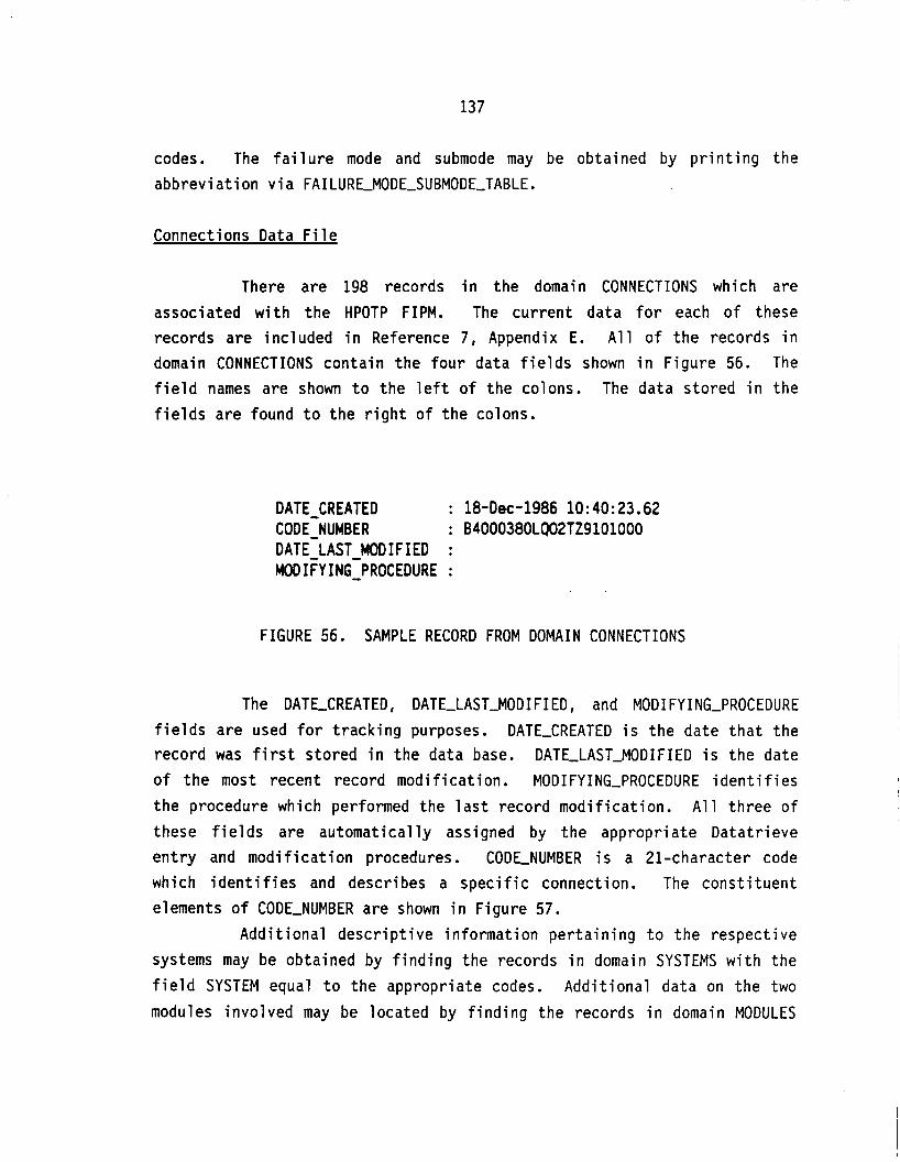
137
codes. The f a i l u r e mode and submode may be obtained by p r i n t i n g the abbrev ia t ion v i a FAILURLMODE-SUBMODE-TABLE.
Connections Data F i l e
There are 198 records i n the domain CONNECTIONS which are
associated w i t h t h e HPOTP FIPM. The cu r ren t data f o r each o f these records are inc luded i n Reference 7, Appendix E. A l l o f t he records i n domain CONNECTIONS conta in the f o u r data f i e l d s shown i n F igure 56. The f i e l d names are shown t o the l e f t o f t he colons. The data s to red i n the f i e l d s a re found t o t h e r i g h t o f t h e colons.
DATE-CREATED COD E-NUMB E R DATE LAST M O D I F I E D : MODIFY ING-PROCEDURE - :
: 1 8 - D e c - 1 9 8 6 10: 40: 23.62 : B4000380LQO2TZ9101000
FIGURE 56. SAMPLE RECORD FROM DOMAIN CONNECTIONS
The DATE-CREATED, DATE-LAST-MODIFIED, and MODIFYING-PROCEDURE f i e l d s a re used f o r t r a c k i n g purposes. DATE-CREATED i s t he date t h a t t he record was f i r s t s to red i n the data base. DATE-LAST-MODIFIED i s the date o f t h e most recent record mod i f i ca t ion . MODIFYING-PROCEDURE i d e n t i f i e s t h e procedure which performed the l a s t record mod i f i ca t i on . A l l t h ree o f these f i e l d s a re au tomat ica l l y assigned by the appropr ia te Data t r ieve e n t r y and m o d i f i c a t i o n procedures. CODLNUMBER i s a 21-character code which i d e n t i f i e s and descr ibes a s p e c i f i c connection. The cons t i t uen t elements o f CODE-NUMBER are shown i n F igure 57.
Add i t iona l d e s c r i p t i v e in fo rmat ion p e r t a i n i n g t o the respec t ive systems may be obtained by f i n d i n g the records i n domain SYSTEMS w i t h the f i e l d SYSTEM equal t o the appropr ia te codes. Add i t iona l data on the two
modules invo lved may be located by f i n d i n g the records i n domain MODULES

138
w i t h SYSTELMODULE equal t o the respec t ive codes. The connect ion type and q u a l i f i e r may be obtained by p r i n t i n g t h e abbrev ia t ion v i a
CONNECTION-TABLE.
B 4 0 0 0 3 8 0 L Q 0 2 T Z 9 1 0 1 0 0 0
1 - 2 - 3 - 4 -
5 - 6 -
S Y STEM-A S Y STEM-I-lODULE-A
CONNECTION UNANTICIPATED-CONNECTION
SYSTEM-B S Y STEM-MODU LE-B
FIGURE 57. ELEMENTS CONTAINED I N CODLNUMBER
F a i l u r e In fo rmat ion Propaqations Data F i l e
A l l o f t h e 8213 records i n the domain PROPAGATIONLB400 are associated w i t h t h e HPOTP FIPM. A p a r t i a l l i s t i n g o f t h e cu r ren t data f o r each o f these records i s inc luded i n Reference 7, Appendix F. A l l o f t he records i n domain PROPAGATIONLB400 conta in the 20 data f i e l d s shown i n F igure 58. The f i e l d names are shown t o the l e f t o f t he colons. The data s to red i n t h e f i e l d s are found t o the r i g h t o f t h e colons.

139
DATE CREATED : 1 8 - A p r - 1 9 8 6 13:31:20.30 F M C O ~ E : B4000010FAVF- - - -0000 CODE-NUMBER : B4000010ME- -FB4000050 SIGNAL-TYPE : VIBRATION S I GNAL-UN I T S : ACCELERATION-G DIMENSIONS : 1
: 1 MAX FREQ-OR-TIME : 3
FT UNITS- : HERTZ PARAMETER : AMPLITUDE PARAMETER-UNITS SYMPTOM-DURATION : 1
I ND I CATES-FA I LURE COMMENT1 V IBRATION AMPLITUDE CHANGES WITH CRACK GROWTH COMMENT2 NATURAL FREQUENCY MAY CHANGE AS A FUNCTION OF CRACKING COMMENT3 P O S S I B I L I T Y OF TRENDING GROSS VIBRATION AND TEMPERATURE LEVELS DATE LAST-MODIFIED : 2 - S e p - 1 9 8 6 1 4 : 2 2 : 18.33
S I GNAL-QUAL I TY
MIN-FREQ OR-TIME : 2
: SAME AS SIGNAL U N I T S
PER 100-OF-ONSET : 2 : T
MODIFY ING-PROCEDURE : FIP-MODIFY
FIGURE 58. SAMPLE RECORD FROM DOMAIN PROPAGATIONS-B400
The DATE-CREATED, DATLLASTJIODIFIED, and MODIFYING-PROCEDURE f i e l d s a re used f o r t r a c k i n g purposes. DATE-CREATED i s t h e date t h a t the record was f i r s t s to red i n the data base. DATE-LAST-MODIFIED i s t he date o f t h e most recent record mod i f i ca t ion . MODIFYING-PROCEDURE i d e n t i f i e s the procedure which performed the l a s t record mod i f i ca t ion . A l l th ree o f these f i e l d s a re au tomat ica l l y assigned by the appropr ia te Data t r ieve e n t r y and m o d i f i c a t i o n procedures. FMCODE i s t he 20-character code which i d e n t i f i e s t h e p a r t i c u l a r f a i l u r e mode being propagated. The elements o f
t h i s code a re descr ibed i n the previous subsect ion on f a i l u r e modes. CODE-NUMBER i s t he 21-character code which s p e c i f i e s the connection t o
which t h e g iven f a i l u r e in fo rmat ion has propagated. The in fo rmat ion contained i n t h i s code i s discussed i n the e a r l i e r subsection on

140
connections. SIGNAL-TYPE identifies the physical nature of the failure information such as vibration, thermal, etc. SIGNAL-UNITS are the units of measure associated with the specified signal. DIMENSIONS is the spatial resolution which can be obtained from a specific signal type (e.g., thermal is a one-dimensional signal while acoustic can provide two- dimensional information). SIGNALQUALITY is an estimate of the relative strength of the given failure signal at this particular location (connection) . MALFREQ-ORTIME and MIN-FREQ-ORTIME define the frequency/time range associated with this signal. FT-UNITS are the physical units associated with the maximum and minimum frequency/time. PARAMETER identifies the sensitive or important feature of the failure signal such as amplitude. PARAMETERUNITS are the units assigned to a particular parameter. SYMPTOM-DURATION is an estimate of the time between the initiation of a detectable, symptomatic signal and the actual component failure. PERIOD-OF-ONSET is a projection of the operational time which can be accumulated before failure symptoms are likely to occur. INDICATES-FAILURE is a true or false statement of whether the given failure information indicates that the failure has occurred. COMMENT1 through COMMENT3 are brief statements which provide additional data pertinent to the failure information propagation being described. All of the various unit fields are assigned by the Datatrieve input procedure based on predefined relationships.
Additional descriptive information pertaining to the given FMCODE may be obtained by finding the record in domain FAILUREMODES with the identical value for this field.
References Data Fi 1 e
There are three records in the domain REFERENCES which are associated with the HPOTP FIPM. The current data for each of these records are included in Reference 7, Appendix G. All of the records in domain REFERENCES contain the 13 data fields shown in Figure 59. The field names are shown to the left of the colons. The data stored in the fields are found to the right of the colons.

141
DATE-CREATED : 20-Nov-1986 15:47:21.52 REFERENCE-NUMBER : RDOOl AUTHOR1 AUTHOR2 AUTHOR3 AUTHOR4 DOCUMENT-TITLE SPACE TRANSPORTATION SYSTEM TECHNICAL MANUAL, SSME DESCRIPTION AND OPERATION (INPUT DATA), SPACE SHUTTLE MAIN ENGINE, PART NUMBER RS007001 DOCUMENT-SOURCE : ROCKETDYNE DOCUMENT-NUMBER : E41000, RSS-8559-1-1-1 DOCUMENT-DATE : 05-APR-1982 CONTRACT-NUMBER : NAS8-27980 DATE-LAST-MOD IF IED : MODIFY ING-PROCEDURE :
FIGURE 59. SAMPLE RECORD FROM DOMAIN REFERENCES
The DATLCREATED, DATLLASTJODIFIED, and MODIFYING-PROCEDURE f i e l d s a re used f o r t r a c k i n g purposes. DATE-CREATED i s t h e date t h a t t he record was f i r s t s to red i n t h e data base. DATE-LAST-MODIFIED i s t h e date o f t h e most recent record mod i f i ca t ion . MODIFYING-PROCEDURE i d e n t i f i e s t h e procedure which performed t h e l a s t record mod i f i ca t i on . A l l t h ree o f these f i e l d s a re au tomat ica l l y assigned by the appropr ia te Data t r ieve
e n t r y and m o d i f i c a t i o n procedures. REFERENCE-NUMBER i s a f i ve -cha rac te r code assigned t o t h e reference dur ing data en t r y . This number is generated by t h e i n p u t procedure. AUTHOR1 through AUTHOR4 are any authors which are l i s t e d f o r t he reference being c i t e d . DOCUMENT-TITLE i s the t i t l e o f t h e repo r t , book, e tc . DOCUMENT-SOURCE i d e n t i f i e s the organ iza t ion o r company which produced the i tem being referenced. DOCUMENT-NUMBER i s any i d e n t i f y i n g number assigned by the source o rgan iza t i on o r company. DOCUMENT-DATE i s t he date o f pub l i ca t i on . CONTRACT-NUMBER i nd i ca tes the government con t rac t number under which the work was performed.

142
(This page intentionally blank)

143
SSME FIPM DRAWINGS
In addition to the high-pressure oxidizer turbopump FIPM drawing discussed in the previous section, FIPM drawings were generated for the following nine SSME systems:
A150 - Heat exchanger (HE) A200 - Main injector A330 - Main combustion chamber (MCC) A340 - Nozzle A600 - Fuel preburner (FPB) A700 - Oxidizer preburner (OPB) 8200 - High-pressure fuel turbopump (HPFTP) B600 - Low-pressure fuel turbopump (LPFTP) B800 - Low-pressure oxidizer turbopump (LPOTP)
All of the FIPM drawings are included in Appendix B of this report. The heat exchanger (A150) FIPM drawing depicts a total of 36
modules. Of this number, 24 are modules of A150 while the remaining 12 are modules of external systems. The drawing also shows 68 connections. 51 of these are internal to this system while 17 are external connections. A total of 69 failure modes have been identified for the various modules comprising system A150.
The main injector (A200) FIPM drawing depicts a total of 52 modules. Of this number, 36 are modules of A200 while the remaining 16 are modules of external systems. The drawing also shows 123 connections. 77 of these are internal to this system while 46 are external connections. A total of 95 failure modes have been identified for the various modules comprising system A200.
The main combustion chamber (A330) FIPM drawing depicts a total of 28 modules. Of this number, 18 are modules of A330 while the remaining 10 are modules of external systems. The drawing also shows 42 connections. 29 of these are internal to this system while 13 are

144
external connections. A total of 48 failure modes have been identified for the various modules comprising system A330.
The nozzle (A340) FIPM drawing depicts a total of 54 modules. Of this number, 41 are modules of A340 while the remaining 13 are modules of external systems. The drawing also shows 88 connections. 63 of these are internal to this system while 25 are external connections. A total of 132 failure modes have been identified for the various modules comprising system A340.
The fuel preburner (A600) FIPM drawing depicts a total of 43 modules. Of this number, 27 are modules of A600 while the remaining 16 are modules of external systems. The drawing also shows 100 connections. 70 of these are internal to this system while 30 are external connections. A total of 89 failure modes have been identified for the various modules comprising system A600.
The oxidizer preburner (A700) FIPM drawing depicts a total of 43 modules. Of this number, 27 are modules of A700 while the remaining 16 are modules of external systems. The drawing also shows 94 connections. 62 of these are internal to this system while 32 are external connections. A total of 85 failure modes have been identified for the various modules comprising system A700.
The high-pressure fuel turbopump (B200) FIPM drawing depicts a total of 101 modules. Of this number, 94 are modules of B200 while the remaining 7 are modules of external systems. The drawing also shows 197 connections. 181 of these are internal to this system while 16 are external connections. A total of 281 failure modes have been identified for the various modules comprising system B200.
The low-pressure fuel turbopump (B600) FIPM drawing depicts a total of 54 modules. Of this number, 47 are modules of B600 while the remaining 7 are modules of external systems. The drawing also shows 99 connections. 89 of these are internal to this system while 10 are external connections. A total of 123 failure modes have been identified for the various modules comprising system B600.
The low-pressure oxidizer turbopump (B800) FIPM drawing depicts a total of 49 modules. Of this number, 44 are modules of B800 while the

145
remaining 5 are modules of external systems. The drawing also shows 89 connections. 81 o f these are internal to this system while 8 are external connections. A total of 150 failure modes have been identified for the various modules comprising system B800.

146
(This page intentionally blank)

147
HPOTP DIAGNOSTIC ASSESSMENT
Present Instrumentation
There is presently instrumentation for eight different measurements on the HPOTP. These measurements are shown in Table 17. These sensors can pick up information for many failure modes as shown in the FIPM output listings in Table 18. The problem is in isolating the component failing from the information available. This is especially true for the accelerometers, which can detect information for over 81 failure modes. Also, most of the information available cannot directly determine if a failure i s imminent or has occurred, but can only give an indication of the environment the components are subjected to for trending information. On the positive side, only a few of the failure modes have been a problem, so even though their is a possibility of many failure modes having the same signature, there is a high probability that it can be narrowed down to a few failure modes.
The FIPM model assumes that the system depicted is in the near- normal state and that it models the propagation of failure information, not the failure itself. The failure information at each sensor will be discussed along with the possible capability to discriminate the individual failure modes from the information at each sensor. Then, with knowledge of the critical failure modes and instrumentation under development, possible test points have been investigated for isolation o f
the important failure information. These test points will be discussed later in this section.

148
c 0
c, m u 0
.r
r 0 c, 0. L V VI a
.C
.r
n
c 0 c, u a c e 0 V
.r
c, c W
L v) m
5
P
n c
I Y- O
E m aJ L
8
z
s m 0 0
m LL
N 0
s 4: m m 0
8
0) cn L c uaJ rnL nv)
C L
m
.- a n a
v)
8"
d
n I-
I
Y- 0
8
5 0, L GaJ m c n c c 3 m 0 -
m a aJcn C L u m E C m u
v) m -- nk
tun
0 0, m 0 0 0 e m LL
(v 0
s 2 0
0 0 0 e m
a cn L m r ue, LnL
VI
-7 a a m n a J
!$ I
N
0 m Io 0 0 s m LL
N 0
s 0 N W 0 0 0 e m
a L VI v) 0,
0 . L E n a no, cn L L w m c C L V
a
av) n e-
n
0, > 0 U
U
n
v)
P m v)
0 m tn 0 0 s m LL
N 0
s 0 N W 0 0 s m
2
B 5'
S c, m L aJ
0.0,
n a J Ell
L L o m E C L W a m n e- a n n L
e
n c
I I a J
u r n - L o m
Y - r *- u e m
g
9s v ) a J m e W 0-
c , L o s I C
n
0 m m m 0 m U LL
4
U W
0
0 0
2
s m
aJ L c, m L W CT
a J c c .r aJ L L cc
V nv) c e-
I
a
5 n c n a m
8"
m
0 0 rD 0 cu Io 0 0 0 0 0 e
LL L L
I V
U W
s m m
W n
Y x s m m m 0
0 0 0 N V m
E:
h
0 o m m m e -

149
TABLE 18. F A I L U R E INFORMATION FOR CURRENT INSTRUMENTATION
CODE-WER : A 1 W 8#30 QA HO f B 4 0 0 WOO SIWL-TYPE : M#UL (DEORCLS-K) PARMETER : A Y P L I W E ( W E AS SI- UNITS)
1 B 4 0 0 OO40 FA TF 2 8 4 0 0 0 0 4 0 W E R 3 B 4 0 0 OOOO FA TF 4 UOO 0120 W ER 6 ,400 0167 FA Tf 6 8 4 0 0 O O O O W E R 7 B 4 0 0 0120 FA TF 0 UOO 0283 FA TF @ B 4 0 0 O O O O F A T F
10 B 4 0 0 W O O U R E R
1 1 1 1 1 1 1 1 1 1
2 2 2 2 2 3 3 3 4 4
1 2 3 4 6 a 7 8 8
10 11 12 13 14 I S
1 1 1 1 1 1 1 1 1 1 1 1 1 1 1
0 1 1 1 1 1 1 2 2 2 2 2 3 3 3
1141 1 E* 1 E M l 1 E* lE+Ol 1 E* 1 E 4 1 lE+01
1 E* i e+Oi
1 E+Ol 11+01 1E+Ol 1 E 4 1 1 E 4 1 1E+01 1c+01 ( E a 1 1E*1 1 c e 1 l e e 1 1c+01 1E-1
lE+01 ir+Oi
lE-01 1E-02 1E-01 1E-02 1E-01 1E-02 1E-01 1E-01 1E-01 1E-02
. . 1E-01 1E-01 1s-01 1E-01 1E-01 It-01 1E-01 (E-01 1E-01 (E-01 1E-01 1E-01 1E-01 (E-01 1E-01
St- SECONDS
SE WNDS
1 E M 1 ( E M 2 l E M 1 1E-2 1 E 4 1 1 E M 2 1E+O1 1E*1 l E + O l 1 E M 2
lE* l 1E+01 1 E M l 1 E M 1 1 E M l lE+o l 1E+O1 lE+01 1c-1 1E+O1 1E+01 ( E M 1 1E-1 1LM1 1 E M 1
1 E 4 2 1 E+02 1 E+02 1E+02 1 E+02 1 E+02 1 E M 2 1 E+02 1 E+02 lE+O2
1E+02 l E M 2 1 E+02 1 E+02 1 E 4 2 1 E+02 1 E+02 1 E+02 1E+02 1 E+02 1 E+02 1 E a 2 1E-2 1 E M 2 1 E+02
F F F F F F F F F F
c F F F F F F F F f F F F F F

150
TABLE 18. F A I L U R E INFORMATION FOR CURRENT INSTRUMENTATION (CONTINUED)
CODE-MM8ER : 6400 0170 QA HQ T 6400 0180 SIQNAL-TYPE : PRESSURE (PSIA) PARAMETER : W L I W D E ( S U E AS SI- UNITS)
1 6400 0180 LK TL ---- oooo 1 1 2 6400 0 1 7 0 LU TL ---- oooo 1 2
C O D E - m E R : 6400 0 2 6 0 QI HE F C200 @@lo SIGNAL-TYPE : PRESSURE (PSI*) PARAMETER : AMPLITUDE ( S U E AS SI- UNITS)
1 B400 0 2 2 0 D f SD ---- oooo 1 4 2 B400 0200 D f SD ---- oooo 1 4
CODE-UER : 1400 03so L a 02 F ~ a o o aaio SIQNAL-TYPE : PRESSURE (PSIA) PARAMETER : AMPLITUDE ( S U E AS Sf- UNITS)
1 6400 0370 UR CV ---- oooo 1 0 2 6400 0380 YR CV ---- oooo 1 1
C O D E - W E R : 6400 0380 LO 0 2 F B400 0390 SIQNAL-TYPE : PRESSURE (PSIA) PARAMETER : AMPLITUDE (SAME AS SIQNAL UNITS)
1 B400 a 3 0 FA I P ---- oooo 1 0 2 6400 0300 WR CV ---- oooo 1 1 3 9400 0370 WR CV ---- oooo 1 3 4 B400 0 5 9 0 FA I P ---- oooo 1 3 5 6400 0390 FA I P ---- oooo 1 4
WDE-HnaER : B400 0570 YE CP F 6400 0000 SI--TYPE : VIBRATION (ACCELERATION-G) PARAMETER : UlPLItuM (SAME AS SIQNAL UNITS)
1 2 3 4 I 8 7 8 a
1 0 11 12
0400 0070 a Ip 6400 -0 B400 0080 FA V f ---- oooo B400 0 1 2 0 F A I M ---- oooo B400 0230 FA V f ---- oooo B400 0240 f A VF ---- oooo B400 0 2 7 0 f A VF ---- oooo ~ 4 4 0 0 2 8 0 rlr vr ---- oooo B400 0287 FA V f ---- oooo ~ 4 0 0 0287 r1 SL ---- oooo B400 02@3 FA V f ---- oooo 6400 0310 F I SL ---- oooo 6400 0330 FA VF ---- oooo
1 1 1 1 1 1 1 1 1 1 1 1
0 0 0 0 0 0 0 0 0 0 0 0
1 E+03 1 E+03
1 E a 3 1 E+03
1E+OS 1 €+OS
1€+02 1 €+OS lE+OS 1 E+02 1 E+02
1 €+os 1 c+04 1 E+04 1 E+04 1 E+04 lE+04 1 E+04 1 E+04 1 E+04 1 E#4 1 E* 1E+04
1E+00 1E+00
1c+oo lE+00
1L+O1 lE+O1
1 E -02 1E+O1 lE#1 1E-02 1 E -02
1E+Ol 1E+O1 1E+01 1E+01 1E+O1 1c+o1 lE#1 1E#1 lE+Ol lE+O1 1E+O1 1E+O1
HERTZ HERTZ
HERTZ HERTZ
HERTZ HERTZ
HERTZ HERTZ HERTZ HERTZ HERTZ
HERTZ HERTZ HERTZ HERTZ HERTZ HERTZ HSRTZ HERTZ HERTZ HERTZ HERTZ HERTZ
lE+Ol 1E+O1
1€+02 1 E+02
1 E+02 1 E+02
1E#1 1 E+02 1E+02 1E+Ol 1E+Ol
1E+O1 1E#l 1E-01 1 e a 2 1 ~ 2 1 E#2 1E+02 1E+O1 lE+O1 1E#1 1E+Ol 1E+O2
1E+O2 1E+02
1E+02 1€+02
1E+02 1E+02
1 E+O 1 1 E+02 1 E+O2 lE+Ol 1E+Ol
1 E+OO 1E+O1 1E-01 1 E+O2 1 E+02 1 E#2 1 E+O2 1E+02 1E+02 1E+02 1 E+O2 1 E+02
T T
T T
F F
F F F F F
T F F F F F F F T F T F

151
TABLE 18. FAILURE INFORMATION FOR CURRENT INSTRUMENTATION (CONTINUED)
13 14 15 16 17 18 19 2 0 2 1 22 23 2 4 2s 2 s 27 28 2 9 30 31 3 2 33 3 4 35 39 37 38 39 4 0 41 42 43 44 45 46 47 48 49 50 5 1 52 I3 1 4 55 w 5 7 58 19 60 5 1 52 53 e 4 65
0400 0330 rx SL ---- oooo 0400 0350 FA VF ---- oooo 0400 0300 F A IM ---- oooo B400 03- FA V f ---- oooo 0400 0380 FA VF ---- oooo 0400 0390 F A I M ---- oooo 0400 0 5 4 0 FA VF ---- oooo B400 0550 F A VF ---- oooo 0400 0133 FA IM ---- oooo 0400 0157 F A VF ---- oooo 0400 0157 F I SL ---- oooo 0400 0190 WR P I ---- oooo 0400 -90 WR RE ---- oooo
0 7 1 0 WR PT ---- oooo B400 0 7 1 0 UR RE ---- oooo 8400 0720 UR P I ---- oooo 0400 0 7 2 0 WR RE ---- oooo 0400 0730 WR PT ---- oooo 0400 0730 YR RE ---- oooo 0400 0740 WR PT ---- oooo 0400 0 7 4 0 YR RE ---- oooo 0400 0750 CIR RO 1400 0740 B400 0 7 5 0 WR RE 0400 0750 0400 0760 W PT ---- oooo 0400 0760 WR RE ---- oooo B400 0080 FA I M ---- oooo 0400 0 2 9 0 FA VF ---- oooo 0400 0350 FA I M ---- oooo 0400 0380 F A I M ---- oooo 0400 0403 FA VF ---- oooo 0400 0403 F I SL ---- oooo 0400 05bo F I SL ---- oooo 8400 0557 FA VF ---- oooo B400 OS87 FI SL ---- oooo 0 4 0 0 0583 FA VF ---- oooo 0400 0583 FI SL ---- oooo 0400 0153 FA VF ---- oooo 0400 0113 F I SL ---- oooo B400 0750 F A VC ---- oooo 0400 0 4 1 0 FA VF ---- oooo 0400 050O FA VF ---- oooo 0400 0130 F A VF ---- oooo 0400 0170 UR RB 0400 0080 0400 0770 FA VF ---- oooo 0 4 0 0 0790 FA VF ---- oooo 0100 0700 PI SL ---- oooo 0400 0680 FA VF ---- oooo 0400 0680 F I SL ---- oooo 0 4 0 0 ows FA VF ---- oooo 0 4 0 0 OSes F I SL ---- oooo 5400 0570 FA VF ---- oooo 0400 0580 FA VF ---- oooo 0 4 0 0 0580 F I SL ---- oooo
1 1 1 1 1 1 1 1 1 1 1 1 1 1 1 1 1 1 1 1 1 1 1 1 1 1 1 1 1 1 1 1 1 1 1 1 1 1 1 1 1 1 1 1 1 1 1 1 1 1 1 1 1
0 0 0 0 0 0 0 0 0 0 0 0 0 0 0 0 0 0 0 0 0 0 0 0 0 1 1 1 1 1 1 1 1 1 1 1 1 1 1 2 2 2 2 2 2 2 3 3 3 3 3 3 3
1 E M 1E+04 1E+M 1E- 1 E+o4 1E+04 1 E + M 1 E+04 1 E+04 lE* lE+04 1 €+Of 1 E+07 1 E M 7 1E+07 1 E+07 1E+O7 lE+07 1 €+07 1E+07 1 E+07 1 E+03 1E+03 1 E+07 1€+07 1E+04 1 E + M 1 E+04 1E+04 1E+04 1E+04 1E+04 lE+04 1 c*o4 1 E+o4 1 E+o4 1 E+o4 1E+o4 lE+04 1 E + M 1E+04 1E+o4 (E+- 1E+04 1 E+o4 1 E+04 11- 1 E+o4 1c+o4 1 E+04 1 E+04 1 E + M 1 E+04
( E M 1 lE+Ol 1E+01 l t + O l 1E+Ql 1E+O1 1E+Ol 1E+01 1 E a l 1E+Ol I t 4 1 1E+04 lE+04 1 E+o4 1E* 1 E+04 1E+04 lE* 1€+04 1E+04 1E* 1E+O1 1E+01 lE+04 1E+04 1E+O1 1c-1 1E+O1 lE+01 1t-1 1E-1 1E+O1 1E-l lL*1 1E+o1 1 E M l 1E+01 1E+O1 1E+01 I t 4 1 1E+O1 lE+01 1c-1 1E-l lE+01 1 E M 1 1E-1 lE+Ol 1E+01 1E+O1 1 E M 1 1E+O1 1E+O1
HERTZ HERTZ HERTZ HERTZ HERTZ HERTZ HERTZ HERTZ HERTZ HERTZ HERTZ HERTZ HERTZ HERTZ HERTZ HERTZ HERTZ HERTZ HERTZ HERTZ HERTZ HERTZ HERTZ HERTZ HERTZ HERTZ HERTZ HERTZ HERTZ HERTZ HERTZ HERTZ HERTZ HERTZ HERTZ HERTZ HERTZ HERTZ HERTZ HERTZ HERTZ HERTZ HERTZ MRTZ HERTZ HERTZ HERTZ HERTZ HERTZ HERTZ HERTZ HERTZ HERTZ
1E+O1 1 E+02 I t - 0 1 lE+02 1E+02 1E-01 1 E +02 1E+02 1E-01 1E+Ol l E M 1
1E+02 1E+02 1 E+02 1 E+02 1E+02 1E+02 lE+02 1E+02 1E+02 1 E+O2 1E+02 1 E+02 1 E+02 1E-01 1 E+02 l a - 0 1 1E-01 1E*1 1E+0l l e e 1 1E+O1 lE+o l 1E+Ol 1E+O1 1E+O1 1E+O1 1E+02 1E+Ol 1 E+02 1 E+02 ( E e l 1 E M 2
1E*1 1E+02 lE+01 1E+02 1E+O1 lE+02 1 E+02 1E+01
1e+02
leu12
1 E+02 1E+02 1E-01 lE+02 1 E+O2 1E-01 1E+02 1E+02 (E-01 1 E+02 1 E+02 lE+02 1E+02 1E+02 1E+02 1E+02 1 E+02 1 E+O2 lE+O2 1 E+02 1E+02 1E+00 1E+W lE+02 1 E+02 1E-01 1 E+02 1E-01 1E-01 1E+02 1E+02 1 E+02 1E+02 1E+02 1E+02 1 E+02 1 E+O2 1 E+02 1 E+02 1E+0l 1 E+02 lE+02 1E+00 1 E+02 1 E+02 1 E+02 1 E+02 lE+02 1 E+02 lE+02 1E+02 1E+O2 1 E+02
T F F F F F F F F F T T T T T T T T T T T F F T T f F F F F T T F T F T F T F T F F T F F T F T F T F F T
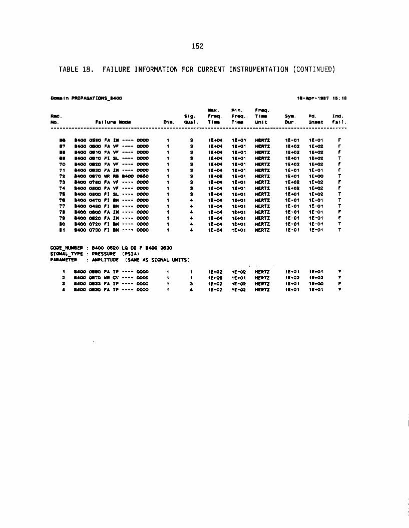
152
TABLE 18. FAILURE INFORMATION FOR CURRENT INSTRUMENTATION (CONTINUED)
66 67 08 om 70 7 1 7 2 73 74 78 76 77 78 7 0 BO 8 1
1400 OSOO f A IM ---- oooo B400 0600 f A VF ---- oooo UOO 0610 f A V f ---- oooo B400 0610 f1 SL ---- oooo B400 0620 f A V f ---- oooo 1400 0630 FA IM ---- oooo B400 0670 UR Itl D400 06- 1400 0780 FA V f ---- oooo 0400 0000 f A V f ---- oooo 0400 0000 F I SL ---- oooo 0400 0470 f1 BN ---- oooo B400 0460 f1 DN ---- oooo 0400 0600 f A I M ---- oooo 8400 0620 FA IM ---- oooo B400 0720 f1 BN ---- oooo B400 0730 f I ON ---- oooo
1 1 1 1 1 1 1 1 1 1 1 1 1 1 1 1
3 3 3 3 3 3 3 3 3 3 4 4 4 4 4 4
UIDE-WMDER : ,400 0620 La 02 r WOO 0630 SI--TYPE : PRESSURE (PSI*) PMAMETER : *WPLINDL (SAME AS SIGNAL UNITS)
1 UOO OSOO FA IP ---- oooo 1 1 2 0400 0670 WR CV ---- oooo 1 1 3 8400 0633 FA IP ---- oooo 1 3 4 B400 0630 FA IP ---- oooo 1 4
1E+04 lE+04 1E+04 1 E W 1 E W 1 E+04 lE+cn 1E+04 1E+04 l E W 1 E W 1E+04 1 c+04 1 E+04 1 E+04 1 E+O4
1E+O2 1E+OS 1 E M 2 lE+O2
1 E 4 1 1€+01 1E+O1 1 E 4 1 1E+Ol 1 E 4 1 1 E 4 1 1 E M 1 1c-1 lE+Ol lE+Ol lE+Ol lE+O1 lE+01 1E+O1 1E+O1
1E-02 lE+Ol 1E-02 1E-02
HERTZ HERTZ HERTZ HERTZ HERTZ HERTZ HERTZ HERTZ HERTZ HERTZ HERTZ HERTZ HERTZ HERTZ HERTZ HERTZ
HERTZ HERTZ HERTZ HERTZ
1E-01 1 E+02 1 E+O2 1E+O1 1E+O2 1E-01 1E+O1 lE+OZ lE+02 I t 4 1 1E-01 1E-01 I € - 0 1 1E-01 1E-01 1E-01
1E+O1 lE+OZ 1 E M l 1E+01
1E-01 lE+02 1E+O2 1 E+02 1 E+02 1E-01 1 E+OO 1 E+02 1 E+02 1 E+O2 1E-01 l f - 0 1 1E-01 1E-01 1E-01 1E-01
1E+O1 1 E+O2 1 E+oo 1E+Ol
F F f T F F T F F T T T F F t t
f F f F

153
1. LPOTP Discharge Pressure (HPOTP Pump Inlet) 8400 0350 LO 02 F 8800 9910 PRESSURE
The pressure sensor upstream of the pump may be able to detect cavitation in the pump. An increase in amplitude above 1000 Hz could indicate cavitation. This measurement could be used to trend wear and loads due to cavitation for trending life limits of the affected parts. In conjunction with the discharge pressure and turbine outlet temperature, some determination of the turbopump performance could be made. The performance loss might indicate cavitation, turbine efficiency loss, or other degradation phenomena. It would also help to have flow and temperature information at these points. The pressure sensor can also detect pressure surges that might fracture the ducts upstream of the HPOTP which are not shown on the HPOTP FIPM.
2. HPOTP Discharge Pressure B400 0380 LO 02 F B400 0390 PRESSURE
In conjunction with the inlet pressure and turbine outlet temperature, trending of the performance of the pump. along with cavitation related failure modes may be possible. Also, pressure surges that might fracture the ducts and cause leaks can be monitored for trending information. A large enough pressure surge might warrant inspection of the ducts during post-flight inspection.
3. Preburner Pump Discharge Pressure B400 0620 LQ 02 F 8400 0630 PRESSURE
Trending of preburner pump cavitation is possible along with This monitoring pressure surges that might fracture ducts and manifolds.
measurement may also be helpful in determining overall pump efficiency.
4. Preburner Pump Discharge Temperature B400 0620 LO 02 F 8400 0630 TEMPERATURE
Can be used for trending information about thermally induced loads on components in the preburner pump. Along with the discharge pressure, some assessment of pump performance can be made. It would also be helpful to have flow information and inlet pressure and flow information. Since the performance of both pumps are related, the inlet

154
and outlet sensor information from the main pump could be helpful in evaluating performance.
5. HPOTP Turbine Di scharqe Temperature A150 9930 GA HG F B400 0080 TEMPERATURE
The turbine exhaust temperature measurement can be used for trending information on the thermal loading and possibly the erosion process for the hot gas section parts. Also may help determine preburner problems which are not a part of this FIPM.
6. HPOTP Secondarv Turbine Seal Drain Pressure B400 0170 GA HG T B400 0180 PRESSURE
This pressure measurement may detect excess leakage in turbine seals which could be critical if hydrogen-rich hot gas mixes with liquid oxygen from the pump-end of the turbopump.
7. HPOTP Intermediate Seal Helium Purqe Pressure 6400 0260 GA HE F C200 9910 PRESSURE
This pressure measurement can be used to determine that the proper helium pressure is supplied to the intermediate seal to separate LOX from hydrogen-rich hot gas. High pressure may indicate clogging in the supply line and low pressure might indicate excessive leakage in seals or upstream supply problems. If the helium supply to the seals is cut-off or restricted, a catastrophic failure o f the pump would be imminent as hydrogen gas would mix with LOX and into the bearings.
8. HPOTP Radial Accelerometers B400 0570 ME CP F 6400 0600 VIBRATION
The housing accelerometers pick up almost every vibration related failure mode signal in the pump. There is a wealth of information available, but great difficulty in isolating the failure modes. General prognostic monitoring of dynamic loading may be achieved with the accelerometers, but this will not be very precise and will require research into developing a life assessment o f each component in relation to the vibration signal and time. Detection of bearing failure modes in the nearby 1st and 2nd bearings may be possible since the accelerometers

155
are close to the bearings and the signal strength is good. Some seal rubbing failure modes may be detectable since they will produce distinctive spikes in the frequency domain related to the operating RPM of the shaft.
Test Point Analvsis for Possible Future Instrumentation
There are several instrumentation concepts under development to These failure modes and the monitor for several important failure modes.
i nstrumentat i on under devel opment are :
Bearing faults (wear, pitting, & ball -cage resonance)
Turbine blades
Performance parameters
Bearing Deflectometer, Isotope Wear, Acoustic Emission Sensor
Optical Pyrometer
Shaft Speed Sensor Ultrasonic Flowmeter
FIPM output of several test points that correspond to these sensors and several other test points that show promise are listed in Table 19 and are analyzed for their potential to monitor various failure modes in the following paragraphs.

156
TABLE 19. F A I L U R E INFORMATION FOR POSSIBLE FUTURE INSTRUMENTATION
a D E - m E R : D 4 0 0 oobo ME -- F 0400 0140 SIan*L-TYPE : THE- (DCQREES-K) PAlULlLtER : NWLITWE (SAME AS SI- WITS)
1 D400 0130 DF SD ---- oooo 1 1 2 0400 ooso FA tu ---- oooo 1 2 3 0400 0080 FA TF ---- oooo 1 2 4 0400 0050 FA VF ---- oooo 1 2
WDC_WW.ER : 0400 oobo WE -- C 0400 0140 SI--WPE : VIBRATION (*CCLLERATION-Q) P-ER : mLIruDt (SAME AS SI- WITS)
1 2 3 4 S e 7 6
1 0 1 1 12 13 14 I S 16 17 18 1s 20 2 1 22 23 24
a
0400 0 4 1 0 UR RI 0400 0170 0400 0410 UR M 0400 0100 0400 0410 UR RI 0400 OlDO 0400 0410 UR M 0400 02- 0400 0070 FA IY ---- oooo 0400 0070 UR M 0400 0000 0400 0070 UR M 0400 0080 0400 O l e o f A w ---- oooo 0400 o400 f A IY ---- oooo 0400 o400 UR U D 4 0 0 0300 0400 o400 UR RB D 4 0 0 0370 D 4 0 0 0 4 4 0 FA VF ---- oooo D400 0 1 8 0 FA VF ---- oooo 0400 01% UR U B400 0110 D400 0470 PI BN ---- oooo 0400 0480 FI w ---- oooo WOO 0720 FI BN ---- oooo uoo 0730 rI BN ---- oooo UOO oo#) r A IY ---- oooo 0400 0140 r A w ---- oooo ~ 4 0 0 o m r1 SL ---- oooo D 4 0 0 0 0 8 O U R R B U O O O W O 0400ooboURwUOOooM) UOO 0 4 1 0 r A w ---- oooo
1 1 1 1 1 1 1 1 1 1 1 1 1 1 1 1 1 1 1 1 1 1 1 1
0 0 0 0 1 1 1 1 1 1 1 1 2 2 2 2 2 2 3 3 3 4 4 B
1 D 4 0 0 0430 UR PT ---- oooo 1 0 2 0400 0430 UR RE ---- oooo 1 0 3 0400 0450 a PT ---- oooo 1 0 4 0400 0460 UR RE ---- oooo 1 0 S UOO 0010 FA lT ---- oooo 1 2 6 0400 0070 FA VF ---- oooo 1 2
1 E M 1 E* 1 E- 1 E W
It- 1 €+os lE+OS 1 €+os 1 L+04 1 E M lE+O8 lE+04 1E+04 1 E M 1E- 1 E+04 1 E+04 1E- 1 E+04 1E+04
1 E+04 1E+04 1E+04 lE+04 1 E- l E- 1E+04
i t u n
lE+Ol lE+Ol 1c-1 1E+O1 1 E* 1 E-
1E-02 1E+O3 1 E+O3 1 E+O3
1E+O1 1E+O1 lL+Ol 1E+O1 1E+O1 1E+Ol lE+Ol 1 E M 1 1E+O1 ( E M 1 lE+Ol lE+Ol 1E+Ol 1E+O1 1E+O1 1E+Ol lL+O1 1L+Ol 1E+O1 lL+Ol lE+O1 1E+O1 1E+O1 1E+O1
1E-01 1 t -01
IC-01 l t + O l 1 E+O3
le-oi
SECONDS O E M SECOWOS S L M
HERTZ HERTZ HERTZ HERTZ HERTZ HERTZ HERTZ HERTZ HERTZ HERTZ HERTZ HERTZ HERTZ HERTZ HERTZ HERTZ HERTZ M R T Z WRTZ HERTZ HERTZ HERTZ HERTZ HERTZ
S E M SECOWOS st- S E M SI- S E W S
lE+02 1E-02 1E+O3 1 E+O3
1E+O1 1E+O1 1L+O1 1E+O1 I t - 0 1 1E+O1 lE+O1 lE+O2 I t - 0 1 1E+O1 1E+Ol 1E+O2 lE+02 lE+O1 1E-01 It-01 1L-01 1E-01 1E-01 1 c+O2 1E+O1 1E+O1 1E+O1 1 E+O 1
1E+Ol 1E+O1 1E+O1 lE+Ol 1c+O1 1 E+03
lE+Ol 1E-02 1 E+O3 1E+O3
1 E+OO 1 E M 1 E+OO l t M 1E-01 1€+00 1E+OO lE+02 1E-01 l t M 1 E M lE+02 lE+O2 1 E M (E-01 I t - 0 1 1L-01 It-01 1E-01 1 E+O2 lE#2 lt- 1 E M 1E+Ol
1E#3 1E+O3 1E+O3 1 E+O3 1 E a 2 1E+O3
T T T T
T f T T F T T F f T T f F T T T T T F F T T T T
T T T f T T
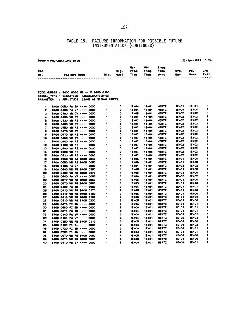
157
TABLE 19. FAILURE INFORMATION FOR POSSIBLE FUTURE INSTRUMENTATION (CONTINUED)
W O E - M E R : B400 0070 ME -- F UOO 0150 S I m - T Y P E : VIBRATION (*CCELERATIffl-Q) PARMETER : MPLITUOE ( S M E AS SI- UNITS)
1 2 3 4 1 1 7 8 8
10 11 12 13 14 15 16 17 18 19 2 0 2 1 22 2 3 2 4 2 5 2 6 27 28 2 9 30 3 1 32 33 3 4 35 30 37
39 40
a8
B400 0050 FA I M ---- oo00 ~ 4 0 0 0400 FA vr ---- oooo B 4 0 0 0400 VR CV ---- oooo DUX) 0430 UR PT ---- oooo B 4 0 0 0430 NR RE ---- oo00 1400 0450 VR PT ---- oooo B400 0450 YII RE ---- oo00 DUX) 0470 a PT ---- oo00 DUX) 0470 RE ---- oooo DUX) 0480 UR PT ---- oo00 B 4 0 0 0480 VR RE ---- oooo B400 0480 YR PT ---- oooo B 4 0 0 0480 UR RE ---- oooo B400 OS20 a PT ---- oooo B400 0 5 2 0 YR RE ---- oooo B 4 0 0 0050 UR RB B400 0040 B400 0050 VR RB B400 -0 uoo oleo r A vr ---- oooo ~ O 4 O O ~ R B B ~ o # o UOO O4OO a RB B400 0370 B400 0440 FA W ---- oooo B 4 0 0 0870 YR M B400 -0 B400 0870 UR RB B400 W80 B400 O4OO FA I M ---- oooo DUX) 0 4 1 0 VR M B400 0170 DUX) 0 4 1 0 YR M B400 0180
B400 0 4 1 0 a RB B400 0200 ~ 4 0 0 0470 r I BN ---- oooo ~ 4 0 0 0480 r1 BN ---- oooo B400 0070 FA I M ---- oo00 ~ 4 4 0 0140 r A vr ---- oooo DUX) 0 1 5 0 FA W ---- oooo B400 0150 UR RB B400 0110 B400 0180 F I SL ---- oooo B400 0 7 2 0 f I W ---- oooo B400 0730 F I Iw ---- oooo B400 0070 a M DUX) OQO B400 0070 a W DUX) 0080 uoo 0410 rA vr ---- oooo
BMO 0410 UR RB BMO 01.0
1 1 1 1 1 1 1 1 1 1 1 1 1 1 1 1 1 1 1 1 1 1 1 1 1 1 1 1 1 1 1 1 1 1 1 1 1 1 1 1
0 0 0 0 0 0 0 0 0 0 0 0 0 0 0 1 1 1 1 1 1 1 1 2 2 2 2 2 2 2 3 3 3 3 3 3 3 4 4 5
1E+04 1E+04 lE* l a 4 7 1 E+O7 1 E+O7 1E+O7 1 E M 7 1 E M 7 1 E+O7 1E+O7 1 €+Of 1E+O7 1 E 4 7 1 E 4 7 1 E a 1 E a 1 E+04 1 E- 1E- 1 E+04 1 E M 1 E M 1 E+04 I t a 1 E- 1 c* 1 E M 1E+04 1 E+04 1E+04 1 E+04 lE+04 1 E a 1E+04 l E W 1E+04 1 E M 1 E a 1 L+04
1E+O1 lE+O1 1E+Ol 1E+04 1 E+04 1 E+04 11- 11- 1 E* 1E+04 1E+04 1 E+04 1 E+04 1 E+04 1E+04 1 E 4 1 lE+Ol 1E+O1 1E+Ol 1 E 4 1 l f + O 1 lE+O1 1 E+O 1 lE+Ol 1E+Ol lE+Ol ( L a 1 lE+Ol 1E+O1 lE+Ol lE+Ol lE+Ol lE+O1 l E # l 1E+O1 lE+Ol 1E+Ol lE4-01 lE+Ol 1E+Ol
HERTZ HERTZ HERTZ HERTZ HERTZ HERTZ HERTZ HERTZ HERTZ HERTZ HERTZ HERTZ HERTZ H E R R HERTZ H E R R HERTZ HERTZ HERTZ HERTZ HERTZ HERTZ HERTZ HERTZ HERTZ HERTZ HERTZ HERTZ HERTZ HERTZ H E R R HERTZ HERTZ HERTZ HERTZ HERTZ H E R R HERTZ HERTZ HERTZ
1E-01 1E+04 1E+O2 1E-2 l a 4 2 1 E 4 2 l E M 2 1E+02 1 E M 2 1 E M 2 1E+O2 1 E+02 ( E M 2 lE-2 1 E 4 2 lE+o l lE+Ol 1E+02 1E+Ol l E + o l 1c-2 1E+O1 1E+Ol 1L-01 1E+O1 1E+Ol 11-1 lE#1 1E-01 1E-01 1E-01 1 E+02 1 E M 2 lE#1 1E+Ol 11-01 1E-01 1E+Ol lE+Ol 1E+O1
1E-01 1 E+04 1 E+O2 l E 4 2 1 E+02 1E+02 1 E+O2 1 E+02 1 E+O2 1€+02 1 E+02 1 E+02 1 E+02 1 E+O2 1 E+O2 1 E+OO 1E+00 1 E+02 1E+OO 1E+00 lE+02 1 E+00 1E+00 1E-01 1 E+OO 1 E+00 1 L+OO 1 E+00 1E-01 I € - 0 1 1E-01 1 L+O2 lE+02 1 E+OO 1€+02 1E-01 1E-01 1 E- 1 E+OO lE+O1
f F F T T T T T T T T T T T T T T F T T F T T F T T T T T T f F F T T T T T T T

158
TABLE 19. F A I L U R E INFORMATION FOR POSSIBLE FUTURE INSTRUMENTATION (CONTINUED)
CODE-HYIER : 0400 0030 QA HQ F 8400 oo40 SIan*L-TYPE : (DEQREES-K) PAIWIETER : WLItUDE (Urn AS SI- WITS)
1 2 3 4 5 e 7 8 8
10
0400 0007 FA TF ---- oooo 0400 0080 YR ER ---- oooo 0400 0 1 2 0 FA TF ---- oooo 0400 0 1 2 0 WR E l ---- oooo B400 0030 UR ER ---- oooo 0400 oO40 FA TF ---- oooo 0400 oO40 YR ER ---- oooo 8400 WOO FA TF ---- oooo 1400 0060 WR ER ---- oooo 8400 0080 FA TF ---- oooo
1 1 1 1 2 1 1 1 1 1
1 3 3 3 4 4 4 4 4 4
WOE-NUIIER : 0400 OOH) QI HG F 0400 OOW SIOUL-TYPE : "HERWL (DEQREES-K) PAIWIETER : AMPLITUDE (SWE AS SI- WITS)
0400 0 1 2 0 FA TF ---- oooo 1400 0120 WR LR ---- oooo B 4 0 0 0040 f A TF ---- oooo 0400 oO40 WR ER ---- oooo 8400 0000 FA TF ---- oooo 0400 OOW WR ER ---- oooo 8400 0080 FA TF ---- oooo 0400 OOIO WR ER ---- oooo
1 2 3 4 5 8 7 8 8
10 11 12 13 14 15 16 17
8400 ooso FA 1Y ---- oooo B 4 0 0 0080 FA TF ---- oooo ~ 4 0 0 ooso r A vr ---- oooo B400 0070 FA IY ---- oooo B 4 0 0 0070 FA TF ---- oooo 8400 0070 r A vr ---- oooo 0400 om0 FA I Y ---- oooo M O O W70 FA TF ---- oooo ~ 4 0 0 0070 r A vr ---- oooo 1400 0140 FA TF ---- oooo 8400 0 1 4 0 FA VF ---- oooo 0400 0150 FA T t ---- oooo 0400 0160 FA T f ---- oooo 0400 oleo r A vr ---- oooo 0400 0400 FA IY ---- oooo 0400 O40O FA TF ---- oooo 1400 0400 r A vr ---- oooo
2 2 2 2 2 2 2 2 2 2 2 2 2 2 2 2 2
0 0 0 0 0 0 0 0 0 1 1 1 1 1 1 1 1
lE+Ol 1 E- 1E+Ol 1 E- l E- lE+O1 1E- 1E+01 1 E+oo lE+Ol
lE+O1 1 E- 1 E M 1 1 E+oo 1E+01 1t- 1E+O1 1 E-
1 E+07 1 E+07 1 E M 7 1 E+07 lE+07 1 E+07 1 E+07 1 C+07 1 E+07 1 E+07 1 Em7 lE+07 1 C+07 1 E+07 lE+07 1 E M 7 1 E M 7
1E-01 1E-02 (E-01 1E-02 1 E -02 1E-01 1E-02 1E-01 1E-02 I t - 0 1
1E-01
1E-01 1E-02 1E-01 1E-02 1E-01 1E-02
l e - 0 2
1E+04 1 E+o4 1 E+oe 1 E+04 1 E+04 1 E* 1 E+04 1 E+04 1 E+04 1E+04 1 E+04 1 E+04 1 E+04 1 E+04 1 E+04 1E+oe 1 E-
S E W S SECONDS
SECOIJDS SECONDS SECONDS
SECOK)S SECONDS SECOWS SI- SECONDS SEComS SECOWDS SECDNDS
HERTZ HERTZ HERTZ HERTZ HERTZ HERTZ HERTZ HERTZ HERTZ HERTZ HERTZ HERTZ HERTZ HERTZ HERTZ HERTZ HERTZ
1 E M l 1E+02 1E+O1 1 E+02 1 E+O2 lE+O1 1 E M 2 1E+O1 1E+O2 1E+O1
1E+O1 1 E+02 1E+01 1E+02 lE+01 1 E+O2 1E+O1 1 E+02
1E-01 (E-01 1E-01 1E-01 1E-01 1E-01 1E-01 1E-01 1E-01 I t - 0 1 I f - 0 1 1E-01 1E-01 1E-01 1E-01 1E-01 1E-01
lE+02 1 E+02 1 E+O2 1E+02 lE+02 1E+02 1E+02 1 E+O2 1E+02 lE+O2
1 E+02 1 E+02 1E+02 1 E+02 1E+O2 11+02 1E+O2 1 E+02
(E-01 1E+02 1E+03 1E-01 1E+O2 1E+03 1E-01 lE+02 1 E+O2 1E+02 1E+02 1 E+02 1 E+02 1E+02 1E-01 1 E+02 1E+03
F F F F F F F F r r
F F F F
F F F
r
t T T T T t T T T T T t T T T T T

159
TABLE 19. F A I L U R E INFORMATION FOR POSSIBLE FUTURE INSTRUMENTATION (CONTINUED)
18 0400 0440 FA W ---- oooo 2 1 18 0400 FA TF ---- oooo 2 1 2 0 0400 OM0 FA VF ---- oooo 2 1 2 1 8400 oibo FA vr ---- oooo 2 2 22 0400 0 4 1 0 FA T f ---- oooo 2 2 2 3 0 4 1 0 FA VF ---- oooo 2 2
1 2 3 4 I 8 7 a 8
10 11 12 13 14 1s 16 17 18 18 20 2 1 22 2 3 24 21 26 27 28 28 30 3 1 32
0400 0 2 4 0 FA VF ---- oooo 0400 0280 FA VF ---- oooo 0400 0287 FA TF ---- oooo 0400 0287 FA VF ---- oooo 0400 0283 FA IP ---- oooo 8400 0283 FA TF ---- oooo 0400 0293 FA VF ---- oooo 0400 0283 LK FA ---- oooo 0400 0293 LK PO ---- oooo 0400 0330 FA VF ---- oooo 0400 0350 FA I N ---- oooo 0400 0350 FA T f ---- oooo 0400 0350 FA VF ---- oooo UOO 0380 FA I N ---- oooo 0400 0380 FA TF ---- oooo 0400 0380 FA W ---- oooo 0400 -eo FA IN ---- oooo UOO ob00 FA W ---- oooo 0400 0810 FA VF ---- oooo 0400 0830 FA VF ---- oooo e400 o w 0 r A I N ---- oooo 0400 0600 FA TF ---- oooo 0400 OOOO FA VF ---- oooo 0400 0620 FA I N ---- oooo 0400 0 6 2 0 FA TF ---- oooo 0400 0 0 2 0 FA V f ---- oooo 0400 0640 FA VF ---- oooo 0400 os50 FA VF ---- oooo 0400 0506 FA TF ---- oooo 0400 OWS FA VF ---- oooo 0400 0200 FA TF ---- oooo uoo 02e0 FA w ---- oooo
2 2 2 2 2 2 2 2 2 2 2 2 2 2 2 2 2 2 2 2 2 2 2 2 2 2 2 2 2 2 2 2
0 0 0 0 0 0 0 0 0 0 0 0 0 0 0 0 0 0 0 0 0 0 0 0 0 0 1 1 1 1 2 2
m D E - W E R : 0400 0290 ME -- F 0400 0850 S I W T Y P E : VIBRATION (ACCELERATIWJ-0) PIRAYETER : W L X N D t (SAME AS SI- UNITS)
1 1400 OO40 FA I Y ---- oooo 1 0 2 0400 OO40 FA VF ---- oooo 1 0 3 uO0oobomwo400oO40 1 0
lL+O7 lE+O7 1 E+O7 1E+O7 1E-7 1 E-7
1 €+Of 1 E+07 1E+O7 1 E+O7
1 E+O7 1 E M 7 1 E+07 1 €+07 1 E M 7 1 E+O7 1E+O7 1 €+Of 1 €+Of lE+O7 lE+O7 1 E a 7 1 E M 7 1€+07 1E+O7 1 E+O7 1 €+Of 1 E-7 1 E-7 1 E 4 7 1 E+O7 1 E M 7 1 €+Of 1 E M 7 1 E 4 7 1 E+O7 1 E+O7
1 €+Of
1 E+04 1 E+04 1 €+os
1 E+04 1 €+04 1 E+04 1 E+04 1E+OS 1E+O4
1 €+04 1 E+04 1 E* 1 E+04 1 E+04 1 €+04 1E+O4 1 E+04 1E+04 1E+04 1 E+04 1 E+04 1 E+04 1 E+04 lE+04 1 €+04 1€+04 1 E+04 1 E+04 1 €+04 1E+04 lE+04 lt+04 1€+04 1E+04 1E+04 lE+04 1 t+04 1 €+04 1E+04 1 E+04 1 €+04
1E+Ol 1E+O1 lE+O1
HERTZ HERTZ HERTZ HERTZ HERTZ HERTZ
HERTZ HERTZ HERTZ HERTZ HERTZ HERTZ HERTZ HERTZ HFRTZ HERTZ HERTZ HERTZ HERTZ HERTZ HERTZ HERTZ HERTZ HERTZ HERTZ HERTZ HERTZ HERTZ HERTZ HERTZ HERTZ HERTZ HERTZ M R T Z HERTZ HERTZ HERTZ HERTZ
HERTZ HERTZ HERTZ
11-01 1E-01 1E-01 1E-01 1E-01 1E-01
1E-01 1E-01 1E-01 1E-01 1E-01 1E-01 1E-01 1E+02 1 E+02 1E-01 1E-01 1E-01 1E-01 1E-01 1E-01 1E-01 1E-01 1E-01 1E-01 l l - 0 1 (E-01 1E-01 1E-01 1E-01 I € - 0 1 1E-01 1E-01 1E-01 1E-01 1E-01 lE-01 1E-01
I t - 0 1 1E+O1 1€+01
1E+02 1E+02 1E+O2 1 E+02 1 E+02 1€+01
1 E+02 1E+02 1E+02 1E+02 1E+W 1 E+O2 1 E+02 1 E+O2 1 E+02 1 E+02 1E-01 1 E+02 1 E+02 1E-01 1 E+O2 1E+02 I f - 0 1 1E+02 1E+02 1 E+O2 1E-01 1 E+02 1 E+02 1E-01 1E+02 1E+02 1E+02 1E+02 1€+02 1 E+O2 1 E+02 1 €+02
1E-01 lE+O1 l E + W
T T T T T T
T T T 1 1 T T T T T T T T T T T T T T T T T T T T T T T T T T T
F F T

160
TABLE 19. F A I L U R E INFORMATION FOR POSSIBLE FUTURE INSTRUMENTATION (CONTINUED)
Dolp i n PROPMATI--0400
R u . sig. r m . ~nq. ti- S p . Pd. Im. No. 011. Qual . T l r TI- Un l t Our. Ommt F a l l .
21-Apr-1087 20:33
YU. M l n . F r r q .
4 1 0 7 8 0 10 11 12 13 14 11 10 17 18 19 20 21 22 23 24 21 2s 27 20 2s 30 31 32 33 34 35 3a 37 38 30 40 41 42 43 44 41 46 47 48 48 50 11 12 13 54 111 56
U O O ~ U R M B . 0 0 ~ UOO WOO FA IY ---- oooo uoo 0100 r A vr ---- oooo 0400 0120 r A vr ---- oooo 0400 0240 r1 SL ---- oooo 0400 0300 UR cv ---- oooo UOO 0370 FA W ---- oooo UOO 0370 UR CV ---- oooo uoo =BO r A vr ---- oooo 0400 o400 r A IY ---- oooo 0400 o400 UR cv ---- oooo 0400 0400 UR M B400 0300 B400 0430 UR PT ---- oooo UOO 0430 UR RE ---- oooo B400 0450 UR PT ---- oooo 0400 0450 UR RE ---- oooo 0400 0470 UR P l ---- oooo ,400 0470 UR RE ---- oooo B400 0400 UR PT ---- oooo B400 0480 UR RE ---- oooo 1400 0400 UR PT ---- oooo 0400 0400 UR RE ---- oooo B400 OMK) WR RB B400 0490 B400 0510 UR M B400 0520 MOO 0520 UR PT ---- oooo B400 OS20 UR RE ---- oooo 0400 MOO FA vr ---- oooo 0400 0630 r A VF ---- oooo 0400 0670 UR RB 0400 0680 0400 0770 r* vr ---- oooo 0400 07.0 FA VF ---- oooo B400 07.0 FI SL ---- oooo 0400 ooao r A vr ---- oooo 1400 0070 UR M 0400 WOO MOO 0120 FA IN ---- oooo ~ 4 0 0 0210 r A vr ---- oooo 0400 0230 r A vr ---- oooo 0400 0250 r A vr ---- oooo 0400 0250 rI SL ---- oooo o m 0270 r A vr ---- oooo 0400 0270 r1 SL ---- oooo uoo 0287 r A vr ---- oooo uoo 0287 rx SL ---- oooo 0400 0203 r A vr ---- oooo 0400 0310 r1 SL ---- oooo HOO 0320 FA vr ---- oooo 0400 0320 r1 SL ---- oooo 0400 0330 r A vr ---- oooo ~ 4 0 0 0330 r1 SL ---- oooo 0400 03BO r A IY ---- oooo 0400 0300 FA VF ---- oooo 0400 0300 FA vr ---- oooo
0400 0200 r A vr ---- oooo
1 1 1 1 1 1 1 1 1 1 1 1 1 1 1 1 1 1 1 1 1 1 1 1 1 1 1 1 1 1 1 1 1 1 1 1 1 1 1 1 1 1 1 1 1 1 1 1 1 1 1 1 1
0 0 0 0 0 0 0 0 0 0 0 0 0 0 0 0 0 0 0 0 0 0 0 0 0 0 0 0 0 0 0 0 0 1 1 1 1 1 1 1 1 1 1 1 1 1 1 1 1 1 1 1 1
1E* 1E+04 1E+04 1 E+04 1 E+04 1E+04 1 E+os 1 E+04 1 E + M lE+04
1E*
1 E+O7 lE+O7 1 €+Of 1 E+O7 (€+Of 1E+O7 1E+O7 1E+O7 1 E+O7 1 E+O7 1E+03 1E+03 1E+O7 1 E+O7 1 E+04 1 E+04 1 E+CH 1E+04 lE+04 lf+04 lE+04 11- 1E+04 lE+04 1E+04 lE+04 1E+04 1 E+04 1E+04 1E+04 1E+04 lE+04 lE+04 1E+04 lE+04 1 E+04 1 E+04 1 E+04 1 E+04 1 E+04
1 e+04
ic+os
1c-1 lE+O1 1E+Ol 1E+O1 1E+O1 lL+Ol 1E+Ol lE+Ol 1E+Ol 1L+O1 lE+Ol 1E+O1 lE+Ol i E + 0 4 lE+O4 1 E+04 1 E+04 1 E+04 lt+O4 1E+04 1 E+04 1 L+04 1 t+O4 lL+O1 1E+O1 1 E+04 1 L+04 1E+O1 lt+Ol 1E+O1 1EM1 1E+O1 1L+Ol 1E+O1 lE+Ol 1E+O1 1E+Ol 1E#l 1E+O1 1E+O1 lE+O1 lE+O1 1E+O1 lE+O1 1E+O1 1E+Ol lE+Ol 1E+O1 lE+Ol 1E+O1 1E+O1 1€+01 lE+Ol
HERTZ HERTZ HERTZ HERTZ HERTZ HERTZ HERTZ HERTZ HERTZ HERTZ HERTZ HERTZ HERTZ HERTZ HERTZ HERTZ HERTZ HERTZ HERTZ HERTZ HE RTZ HERTZ HERTZ HERTZ HERTZ HERTZ HERTZ HERTZ HERTZ HERTZ HERTZ HERTZ HERTZ HERTZ HERTZ HERTZ HERTZ HERTZ HERTZ HERTZ HERTZ HERTZ HERTZ HERTZ HERTZ HERTZ HERTZ HERTZ HERTZ HERTZ HERTZ HERTZ HERTZ
1E+O1 1E-01 lE+02 lE+01 lE+Ol 1 E+O2 1E+O1 1 E+O2 1 E+O2 1 E+O2 1E-01 1 E+02 1E+Ol lE+O2 1€+02 1E+02 1 E+O2 1 E+O2 1 E+02 1E+O2 1 e+o2 1E+02 1E+02 1E+02 1€+02 1E+O2 1 E+O2 1E+02 lE+O2 lE+Ol 1E+02 lE+02 1L+O1 1€+01 lE+ol (E-01 1E+O2 1€+02 1 E+02 1E+Ol 1 E+02 1E+O1 lE+Ol 1c+O1
lE+01 1 EM2 1E+O1 1 E+O2 1E+01 1E-01 1E+02 1E+02
ie+Oi
1 E+OO 1E-01 1E+O2 1E+O1 1 E +02 1€+02 1 E+O2 1E+O2 1 L+O2 1 E+O2 1E-01 1 E-2 1 E+OO 1 E+O2 1E+02 1E+02 1E+O2 1 L+02 1 E+02 1 E+02 1 E+02 1 E+O2 1E+02 1E+OO 1 E+00 1 E+02 lE+02 1 E+02 1 L+O2 1 L+00 1 E+O2 1 E+02 1L+O2 1E+O1 1E+00 1E-01 lE+02 1 E+02 1 E+O2 1E+02 1 E+O2 1 E+O2 1 E+o2 1 E+O2 1 E+O2 1 E+02 1€+02 1E+02 lE42 lE+02 1L-01 1 E+O2 1€+02
T F
F T
F F F F
r
r
r r T T T T T T T T T T T T T T T F
T
F T F T
F F F T F T F T
T
T F T F F F
r
r
r
r
r

161
TABLE 19. FAILURE INFORMATION FOR POSSIBLE FUTURE INSTRUMENTATION (CONTINUED)
I7 58 59 80 81 82 83 8 4 86
67 88 89 70 71 72 73 74 7s 78 77 78 78 80 81 82 83 84 05 8 8 87 88 19 a0 81 82 83 94 96 86 07
B400 03u) FA IM ---- oo00 B400 0410 YR RB B400 0200 B400 OS00 FA VF ---- oooo UOO OS10 FA VF ---- oooo B400 0560 FA VF ---- oooo ,400 0580 FI SL ---- oooo B400 OS70 FA VF ---- oooo B400 OS80 FA W ---- oooo a400 omo r1 SL ---- oooo 0400 OS90 FA IM ---- oooo a400 FA VI ---- oooo B400 0010 FA VF ---- oooo B400 0610 F I SL ---- oooo B400 0620 FA VF ---- oooo B400 -30 FA IM ---- oooo B400 W70 UR RB a400 WSO a400 0780 F A VF ---- oooo b400 0800 FA VF ---- oooo 6400 0800 F I SL ---- oooo B400 0070 YR RB B400 0080 B400 0080 F A I M ---- oooo 8400 0080 FA VF ---- oooo B400 0240 FA VF ---- oooo B400 0310 FA VF ---- oooo a400 03- FA VF ---- oooo B400 0380 FA IM ---- oooo MOO 0630 FA VF ---- oooo B400 0540 FA VF ---- oooo B400 OS66 F A VF ---- oooo B400 OW0 FA IM ---- oooo 0400 0620 FA IM ---- oooo B400 0720 F I BN ---- oooo B400 07JO FI BN ---- oooo B400 0290 FA VF ---- oooo UOO 03- F A 1M ---- oooo B400 0410 FA VF ---- oooo UOO OS50 FA VF ---- oooo a400 OS6s FI SL ---- oooo 0400 0470 F I BN ---- oooo 8400 0400 FI BN ---- oooo B400 OSW FI SL ---- oooo
1 1 1 1 1 1 1 1 1 1 1 1 1 1 1 1 1 1 1 1 1 1 1 1 1 1 1 1 1 1 1 1 1 1 1 1 1 1 1 1 1
1 1 1 1 1 1 1 1 1 1 1 1 1 1 1 1 1 1 1 2 2 2 2 2 2 2 2 2 2 2 2 2 2 3 3 3 3 3 4 4 4
WOE-nUlER : UOO 03M LO 02 f 6400 0390
PARAMETER : IYPLITUDE (SAME AS Sf- UNITS) sroru-npr : rLw (u-MASS PER SEQWD)
1 a400 0360 YR cv ---- oooo 1 0 2 B400 0370 UR CV ---- oooo 1 1
1E+04 1 E+OS 1€+04 1 E+04 1E+04 1E+04 1E+04 1 E+04 1 E+04 1 E+04 1 E+04 1 E W 1E+04 1E+04 1E+04 1E- lE+04 1E+04 lE+04 1 €+os 1 E+04 1 E+04 1 €+04 1 E+04 1 E+04 1 E+04 1E+04 1E+04 1 E+04 1 E+04 1E+04 1 E+04 1E+04 1E+04 1 E+04 1 E+04 1 E+04 1 E+04 1 E+04 lE+04 1 E+04
1 €+os 1 €+os
HERTZ HERTZ HERTZ HERTZ HERTZ HERTZ HERTZ HERTZ HERTZ HERTZ HERTZ HERTZ HERTZ HERTZ HERTZ HERTZ HERTZ HERTZ HERTZ HERTZ HE,RTZ HERTZ HERTZ HERTZ HERTZ HERTZ HERTZ HERTZ HERTZ HERTZ HERTZ HERTZ HERTZ HfRTz HERTZ HERTZ HERTZ HERTZ HERTZ HERTZ HERTZ
HERTZ HERTZ
1E-01 lE+O1 1E+02 1E+02 1E+02 lE+01 1E+02 1E+02 1E+O1 1E-01 1 E+02 1 E+02 1E+O1 1 E+02 1E-01 lE+Ol lE+02 1E+02 1E+O1 lE+Ol 1E-01 lE+01 1E+02 1E+02 1E+02 It-01 1 E+02 lE+02 1E+02 1E-01 1E-01 1E-01 1E-01 1E+02 1E-01 lE+O1 1 E+02 1E-1 1E-01 1E-01 lE+O1
lE+02 1E+02
1E-01 1E* 1 E+02 1 E+02 1 E+02 1 E+02 1 E+02 lE+02 1 E+02 1E-01 1E+02 lE+02 lE+02 1E+02 1E-01 1E* 1 E+02 1E+02 1 E+02 1E* 1E-01 1E+01 1E+02 lE+O2 1 E+02 1E-01 lE+02 1E+02 1E+02 1E-01 1E-01 1E-01 1E-01 1 E+02 1E-01 lE+O1 1 E+02 1 E+02 1E-01 1E-01 1 E+02
lE+02 1E+02
F T F F F T F F T F F F T F F T F F T T F F F F F F f F F F F T t F F T F T T T T
F F

162
TABLE 19. F A I L U R E INFORMATION FOR POSSIBLE FUTURE INSTRUMENTATION (CONTINUED)
DouIn PROPItATIWJ400 21-Apr-1887 20:33
Max. M l n . Froq. R.C. SIg . frrq. fmq. TI- syr. pe. Id. No. D I I . -81. T I N TIN U n I t Cur. Onsot F 8 f 1 .
W D E - m E R : 0400 0410 ME -- t MOO 0060 S I Q N A l j Y P E : RPM (RPM) PARAMETER : MPLITUDE (SAME AS SI- W I T S )
1 0400ooboWRRo0400oO40 1 3 2 0 4 0 0 O O S O W R M B 4 0 0 ~ 1 3 3 0400 0070 WR M 0400 OOW 1 3 4 0400 0070 UR M 0400 0080 1 3 5 0400 0070 UR M 0400 0050 1 3 6 0400 0070 WR M 0400 0060 1 3 7 0400 0150 WR M 0400 0110 1 4
W D E - W E R : 0400 0410 ME -- F 0400 SIWAL-TYPE : RPM (RPM) PARMETER : FREQUENCY (HERTZ)
1 1400 0410 VR RB 0400 0170 1 5 2 0400 0410 YR RB 6400 oiao 1 5 3 0400 0410 UR Ro 0400 0180 1 S 4 0400 0410 WR M 0400 0200 1 5
C O D E - W E R : 0400 0 4 1 0 ME -- t 0400 OW0 SIWAL-TYPE : VIBRATION (ACCELERATION-Q) PARMETER : AWLIfLIDE (SAME AS SI- UNITS)
1 2 3 4 5 I 7 0 8
10 11 12 13 14 15 16 17 16 18 20 21 22 23 24
0440 0070 f A IN ---- oooo 0400 0430 WR RE ---- oooo 6400 0450 WR RE ---- oooo 8400 0470 WR PT ---- oooo 0400 0470 WR RE ---- oooo 0400 0480 WR PT ---- oooo 0400 0480 WR RE ---- oooo B400 0480 WR PT ---- oooo 0400 0480 WR RE ---- oooo 0400 OS20 WR PT ---- oooo 0400 OS20 WR RE ---- oooo 0400 0080 WR PT ---- oooo 0400 0080 WR RE ---- oooo 0400 0710 WR PT ---- oooo 0400 0710 UR RE ---- oooo 0400 0720 WR PT ---- oooo 0400 0720 WR RE ---- oooo 0400 0730 WR PT ---- oooo 0400 0730 UR RE ---- oooo 0 4 0 0 0740 UR PT ---- oooo 0400 0740 UR RE ---- oooo 0400 07M) WR PT ---- oooo 0400 0750 UR RE ---- oooo 0400 UR M 0400 oO40
1 1 1 1 1 1 1 1 1 1 1 1 1 1 1 1 1 1 1 1 1 1 1 1
0 0 0 0 0 0 0 0 0 0 0 0 0 0 0 0 0 0 0 0 0 0 0 1
1 E+04 1 E+04 1 E+04 1E+04
1 E+04 1E+04
lE+03 1 E+03 1 E+03 1 E+03
lE+04 lE+07 1E+07 1 E+O7 1 C+07 1 E+O7 1 E+07 1 E+07 1 C+07 1 E M 7 lE+07 1 E+07
lE+07 1E+O7 1 E-7 1s-7 1 E M 7 1 E+07 1 E a 7 1 E+07 1 E M 7 1 E M 7 1 E a
1 E+O7
1 E+OO 1 E+OO lE+OO 1 E+OO 1 E+OO 1 E+OO 1 E+OO
1 E+02 1 E 4 2 l e 4 2 1 E M 2
1E#1 1E+O4 1E+04 1 E* 1 E+04 1 E+04 1 E+04 1 E+04 1 E+04 1 E+04 1E+04 1E+04 1 E+04 1 E+04 1 E+04 1 E+04 1E+04 1E+04 1E+04 1 E a 1E+04 1E+O4 1 E+04 1E+01
HERTZ HERTZ HERTZ HERTZ HERTZ HERTZ HERTZ
HERTZ HERTZ HERTZ HERTZ
HERTZ HERTZ HERTZ HERTZ HERTZ HERTZ HERTZ HERTZ HERTZ HERTZ HERTZ HERTZ HERTZ HERTZ HERTZ HERTZ HERTZ HERTZ HERTZ HERTZ WRTZ HERTZ HERTZ HERTZ
1 E+02 1 E+02 1E+02 1E+02 1E#2 1E+02 1 E+02
1E+02 1€+02 1E+02 1 E+02
1E-01 1 E +02 1E+02 1 E+OZ 1 E+02 1 E+02 1 E+02 1 E+02 1 E+02 1E+02 1c+02 1 E+02 1€+02 1 E+02 1 E+02 1 €+02 1E+02 1 E+02 1 c+02 1E+02 1E+02 1c+o2 1 E+02 1E+O1
1 E+00 1€+00 1 E+00 1 E+OO 1 t+W 1E+00 1E+W
lE+W lE+00 1 E+00 1 c+oo
1E-01 1 E+02 1 E+02 1 E+OZ 1€+02 1E+02 1E+02 1 E+02 1 E M 2
1€+02 1 E+02 1 E+02 1 E+02 1 c+02 lE+02 1E+02 1E+02 1E+02 1 E+02 1 E M 2 1 E+02 1 E+02 1 L+00
ic+o2
T T T T T T T
T T T T
F T T T T T T T T T T T T T T T T T T T T T T T

163
TABLE 19. FAILURE INFORMATION FOR POSSIBLE FUTURE INSTRUMENTATION (CONTINUED)
25 20 27 20
30 31 32 33 34 31 3e 37 31
40 41 42 43 44 45 46 47 48
BO 51 52 I3 54 55 sa I 7
2a
3a
49
6400 ooso m RD 6400 oom 6400 0070 m RD 6400 6400 0070 M 6400 0080 n400 0400 FA vr ---- oooo 6400 0400 UR cv ---- oooo 6400 0430 UR PT ---- oooo 6400 0450 UR PT ---- oooo 6400 0700 FA V r ---- oooo 6400 0140 FA VF ---- oooo 6400 0150 FA VF ---- oooo 6400 0150 YR u 6400 0110 6400 0180 FA V f ---- oooo m400 Oleo FI SL ---- oooo 6400 0400 W U 6400 O W 0 6400 o*oo UR M 1400 0370 6400 0440 FA VF ---- oooo 6400 0670 FA VF ---- oooo 6400 0670 YR CV ---- oooo 6400 0400 FA I Y ---- oooo 1400 0060 FA VF ---- oooo 6400 0060 F I SL ---- oooo 6400 0670 FA I Y ---- oooo 6400 M70 YR M 6400 0650 6400 -70 WR M 6400 0680 6400 0410 UR M 6400 0170 n400 0410 UR Iu 6400 0180
1400 0410 UR Rm 6400 0200 6400 0410 FA VF ---- oooo 6400 0470 F I W ---- oooo 6400 0400 F I BN ---- oooo 6400 0720 f1 BN ---- oo00 B400 0730 F I BN ---- oooo
0400 0410 UR RE BUM oiao
1 1 1 1 1 1 1 1 1 1 1 1 1 1 1 1 1 1 1 1 1 1 1 1 1 1 1 1 1 1 1 1 1
1 1 1 1 1 1 1 1 2 2 2 2 2 2 2 2 2 2 3 3 3 3 3 3 4 4 4 4 5 5 5 I 5
C O D E - W E R : 6400 OS20 ME -- F 6400 OS30 SI(H*L-TYPE : ACDUSTIC (ACOUSTIC EVENTS) PARAMETER : MPLITUDE ( S U E AS SI- UNITS)
1 6400 OS00 FA VF ---- oooo 2 0 2 6400 0510 FA VF ---- oooo 2 1 3 6400 0530 FA VF ---- oooo 2 1
CODE-nulER : 6400 OS20 ME -- F 6400 OS30 SI--TYPE : VIBRATION (MCELERATIW-Q) P M E T E R : MPLITUDE ( S U E AS 31-L UNITS)
1 6400 0240 FA w ---- oooo 1 0 2 n400 02ao FA VF ---- oooo 1 0 3 0400 0350 FA I M ---- oooo 1 0 4 6400 MOO YR RE ~ 4 0 0 o4ao 1 0 5 6400 OS40 FA VF ---- oooo 1 0
1E* 1E* 1 €+os 1 E+04 1 E* 1E+O7 1E+O7 1E+04 lE+M 1 E+04 1 E M 1 E+04 lE+04 1E- 1 E* 1E+04 lE+04 1E+os 1E+O4 1E+04 1E+04 1E+04 1E+W 1 E + M lE+os 1 E M 1E* 1 E+OS 1€+04 1E+04 lE+04 1 E+04 1 E+04
1E47 1E+O7 1 E+O7
1 E+04 1 E+04 1 E+04 1 E+03 1 E+04
lE+Ol 1E+O1 lE*1 1E+O1 1E+O1 1 E+04 1 E* 1 E+Ol lE+Ol 1E+O1 lE+Ol lE+Ol I t 4 1 1E+O1 1E+O1 1E+O1 1E+o1 1E+O1 1E+O1 1c-1 lE+O! 1E+O1 lE+Ol lE+O1 1E+O1 1E+O1 lE+Ol 1E+O1 lE*l 1E+O1 1E+Ol 1 E e l lE+Ol
1 E+04 1E+04 1 E+04
lE+Ol 1E+O1 1E+O1 lE+Ol lE+Ol
HERTZ HERTZ HERTZ HERTZ HERTZ HERTZ HERTZ HERTZ HERTZ HERTZ HERTZ HERTZ HERTZ HERTZ HERTZ HERTZ HERTZ HERTZ HERTZ HERTZ HERTZ HERTZ HERTZ HERTZ HERTZ HERTZ HERTZ HERTZ HERTZ HERTZ HERTZ HERTZ HERTZ
HERTZ HERTZ HERTZ
HERTZ HERTZ HERTZ HERTZ HERTZ
1E+o1 lE+O1 1 E+O 1 1 E+04 1E+02 lE+O2 1E+O2 1 E+02 1 E+O2 1 E+02 1E+O1 lE+02 1E+O1 1E-1 lE+O1 1E+O2 1E+02 1 E+O2 1E-01 1 E+02 lE+O1 1E-01 1E+Ol lE+O1 lE+O1 1E#1 1c-1 1E+O1 1E+O1 1E-01 1E-01 1E-01 1E-01
1E-01 1E-01 1E-01
lE+O2 1 E+O2 1E-01 1 E+02 1 E+02
1 E + W 1E+W 1 E + W lE+04 1E+02 1E-2 1€+02 1E-2 1 E+02 1 E+02 1 E+00 lE+02 1 E +02 1E+00 l E + W 1E+O2 1E+O2 1E+02 It-01 1E+02 1E+02 1E-01 1€+ 0 0 1E+00 1c+00 1E+00 1c+oo 1 E + W lE+Ol 1E-01 1E-01 1E-01 1L-01
1 E+02 1 E+02 1 E+02
lE+02 lE+02 1E-01 lE+00 1E+O2
T T T F F T T F F F T F T T T F f f F F T F T T T T T T T T T T T
T T T
F F F T F

164
TABLE 19. F A I L U R E INFORMATION FOR POSSIBLE FUTURE INSTRUMENTATION (CONTINUED)
6 7 8 8 10 1 1 12 13 14 11 16 17 18 19 20 21 22 23 24 21 28 27 20 29 30 31 32
B400 0561 F I SL ---- oooo B400 0720 F I W ---- oooo ~ 4 0 0 0730 rr BN ---- oooo B400 0280 FA VF ---- oooo B400 O400 FA I Y ---- oooo 1400 0480 FA VF ---- oo00 B400 OS10 UR R8 B400 OS20 ~ 4 0 0 OS- FA vr ---- oooo B400 0410 FA VF ---- oooo B400 0430 UR PT ---- oooo UOO 0430 VR RE ---- oooo 1400 0470 WR PT ---- oooo B400 0470 UR RE ---- oooo B400 0490 WR PT ---- oooo B400 0490 UR RE ---- oooo B400 0800 FA V f ---- oooo B400 04% UR PT ---- oooo 1400 0410 UR RE ---- oooo B400 0480 UR PT ---- oooo B400 0480 WR RE ---- oooo 6400 OS10 FA VF ---- oooo B400 0520 UR PT ---- oooo B400 OS20 UR RE ---- oooo ~ 4 0 0 01130 FA vr ---- oooo B400 0850 F I SL ---- oooo B400 0470 F I W ---- oo00 B400 0480 F I BN ---- oooo
1 1 1 1 1 1 1 1 1 1 1 1 1 1 1 1 1 1 1 1 1 1 1 1 1 1 1
0 0 0 1 1 1 1 1 2 2 2 2 2 2 2 2 3 3 3 3 3 3 3 3 3 4 4
WDE-HWER : 1400 0770 IIE -- F B400 0790 SIWL-TYPE : ACOUSTIC (ACDUSTIC EVEmS) PARAMETER : Y Q L I N D E ( S H E AS SI- W I T S )
1 B400 0780 FA VF ---- oooo 2 1 2 B400 0780 FA V f ---- oooo 2 1 3 1400 moo FA V f ---- oooo 2 1 4 B400 0770 FA W ---- oooo 2 2 S B400 0790 FA VF ---- oooo 2 2
WDE-WMDER : UOO 0770 YL -- F 1400 07- SIWL-TYPE : VIBRATION (ACCELERATION-G) P W E T E R : YPLITUOE ( S M E AS SI- W I T S )
B400 0470 FI BN ---- oooo ~ 4 0 0 0480 r i BN ---- oooo UOO OS70 FA VF ---- oooo B400 0600 FA V f ---- oooo B400 0620 FA VF ---- oooo ~ 4 0 0 oeeo rt SL ---- oooo- B400 0670 UR RE 1400 06% B400 0720 FA VF ---- oooo B400 0730 FA VF ---- oooo
1 0 1 0 1 0 1 0 1 0 -1 0 1 0 1 0 1 0
1E+04 1 E+04 11- 1 E+04 lE+04 1 E M 1 E+03 1 E+04 1 E+04 1 E+07 1 E47 1 EM7 1 €+Of 1 €+Of 1 €+Of 1 E+04 1 E+O7 1 €+Of 1 E+07 1 E47 1 E+04 1 E+07 1 E+07 1E+04 1 E+04 1 E+04 1 E+04
1 E+07 1 EM7 1E+07 1 E+07 1 E+07
1 E+04 1 L e 4 1 E+04 1 E+04 1E+04 1 E+04 1 E M 1 E+OS 1 E+OS
1E+Ol 1E+O1 1E-l 1E#1 lE+Ol 1E+01 1E+O1 lE+Ol 1E+O1 1L+04 1 E+o4 1f-4
1 E+04 1 E+04 lE+Ol 1 E+04 1 E+04 1 E+04 1 E+o4 1E+O1 1f#4 11+04 lE+Ol 1c+O1 1E#1 1E#1
i e w
1 E+04 1 E+04 1 E* 1 E W 1E+04
lE#1 lE+Ol 1L+O1 1E+O1 lE#1 1E+O1 1E+O1 1E#l 1E#1
WRTZ HERTZ HERTZ HERTZ HERTZ HERTZ HERTZ HERTZ HERTZ HERTZ HERTZ HERTZ HERTZ HERTZ HERTZ HERTZ HERTZ HERTZ HERTZ HERTZ HERTZ HERTZ H E R R HERTZ HERTZ HERTZ HERTZ
HERTZ HERTZ HERTZ HERTZ H E R R
HERTZ HERTZ HERTZ HERTZ HERTZ HERTZ HERTZ HERTZ HERTZ
lE+Ol 1E-01 1L-01 1E+02 1E-01 1E+O1 1 E+02 lE+02 1E+O1 lE+02 1E*2 1 E+02 1€+02 lE+02 1 E+02 1E+02 1f+02 1E+02 1 E+02 1E+02 1E+O2 1E+02 1 E+02 1 E+O2 lE+Ol 1E-01 le-01
1E-01 1E-01 1E-01 lf-01 1E-01
It-01 1E-01 1E+O2 1 E+02 1 E+O2 1E#l lE+Ol 1E#l 1E+Ol
lE+02 (E-01 1E-01 1 E+02 1E-01 1E+O1 1 E+OO 1E+02 1E+01 lE+02 1E+02 1E+O2 1E+02 1E+O2 lE+02 1 E+02 1€+02 1 E+02 1E+02 1E+02 1E+02 1E+02 lE+O2 lE+02 1 E+02 1E-01 1E-01
1E+02 1E+02 1 E+02 1 E+02 1 E+02
1E-01 lE-01 1 E+02 1 E+02 1E+02 1 E+02 1E+00 1E+O1 1E+O1
T T T F F F T F T T T T T T T F T T T T F 1 T F T T T
T 1 T T T
T T F F F T T F F

165
TABLE 19. F A I L U R E INFORMATION FOR POSSIBLE FUTURE INSTRUMENTATION (CONTINUED)
lo 11 12 13 14 15 10 17 18 10 20 21 22 23 24 25 20 27 28 29 30 31 32 33 34
B400 07SO UR RB a400 0740 0400 07- UR M B 4 0 0 0700 0400 0670 UR M B400 0880 B400 WOO UR PT ---- oooo 0400 0600 UR RE ---- oooo B400 0710 UR PT ---- oooo 0400 0710 UR RE ---- oooo B400 0720 YR PT ---- oooo 0400 0720 UR RE ---- oooo m400 0730 UR PT ---- oooo 0400 0730 UR RE ---- oooo B400 0740 UR PT ---- oooo B400 0740 UR RE ---- oooo m4oo 07so FA VF ---- oooo B400 0780 WR PT ---- oooo a400 0780 UR RE ---- woo 0400 0800 FA VF ---- oooo 0400 0800 FI SL ---- oooo B400 0410 FA VF ---- oooo B400 0770 FA VF ---- oooo B400 0780 FA V f ---- oooo B400 0700 FA VF ---- oooo E400 0700 FI SL ---- oooo ~ 4 0 0 0720 r1 BN ---- oooo B400 0730 FI ON ---- oooo
1 1 1 1 1 2 1 2 1 2 1 2 1 2 1 2 1 2 1 2 1 2 1 2 1 2 1 2 1 2 1 2 1 2 1 2 1 3 1 3 1 3 1 3 1 3 1 4 1 4
1 E+03 1 E+03 1 E a 1 E+07 1 E47 1 E+07 1 E+07 lE+07 lE+07 1 E+07 1 E+07 1 E+07 1 E+07 1 E+04 11+07 1 E+07 1 €+04 1 E+04 1 E+04 1 E + M 1 E+04 1 E+o4 1 E+04 1 E+o4 1 E+04
1E-1 lE+O1 1E+O1 1 E+04 1 E+04 1 E+04 1E+04 1E+04 1E+04 1E+04 1E+04 lE+04 1E+04 lE-1 1E+04 1E44 lt#l 1E-l 1L-1 lE+01 1E+O1 lE+oi 1E+O1 1E+01 1c-1
HERTZ HERTZ HERTZ HERTZ HERTZ HERTZ HERTZ HERTZ HERTZ HERTZ HERTZ HERTZ M R T Z HERTZ HERTZ HERTZ WRTZ HERTZ HERTZ HERTZ HERTZ &RTZ HERTZ HERTZ HERTZ
1E+02 1E+02 1E+Ol 1 E+02 1 E+02 1 E+02 1 E+02 1E+02 1E+02 1€+02 1€+02 lE+02 1E+02 lE+02 lE+02 1E42 1E+02 1E+O1 1E+O1 1 E+02 1€+02 1 €+02 1E+01 1E-01 1E-01
lE+00 1 E+OO 1 E* 1 E+02 1 E+02 1 €+02 1E+02 1 E+02 1E+02 1 E+02 1 E+02 1E+02 1 E+O2 1 E+02 1E+O2 lE+02 1 E+02 lE+02 lE+Ol lE+O2 1 E+02 1E+O2 1E+02 1E-01 1E-01
F F T T T T T 1 1 T T T 1 F T 1 F T T F F F T T T

166
At the first connection (Bearing #3 outer race), the signal from bearing #3 failure modes is very strong in the high frequency range. The only other high frequency information is from fracture-generated acoustic signals (see same connection with parameter - ACOUSTIC), but are a lower signal level than the bearing fault signals. The second connection, where Bearings #3 and #4 support block mounts to the pump housing, shows that signals from both bearings can be detected, but the signal levels are much lower and fracture-generated acoustic signals from nearby parts are at the same signal level or higher. This would make it difficult to extract the bearing failure information from that of other components except for the ball-cage resonance type failure, denoted by the FI BN (Friction- Binding) failure mode. The ball-cage resonance failure mode from all the bearings can be readily detected at the second location. The third location, near bearings #1 and #2 spring isolator, shows the capability of detection all the failure modes of these two bearings.
2. Turbine Blade Fracture Detection B400 0050 ME -- F B400 0140 THERMAL B400 0070 ME -- F B400 0150 THERMAL
There are two major failure modes an optical pyrometer can detect and isolate. In looking at the FIPM output for a thermal signal type, fracture of the blades and lack of coolant flow to the rotor from the coolant nozzle ring can be detected. The frequency response of the pyrometer must be very high to measure a temperature profile of each blade as it passes. To detect the lack of coolant flow to the rotor, a long term increase in the RMS value of the temperature is required for detection and isolation. The optical pyrometer could be very useful in reducing the inspection time of the turbine blades. To detect fractures in the 1st (0050) and 2nd (0070) stage turbine blades would require two pyrometers. The only other method of turbine blade crack detection would require an acoustic emission sensor mounted in the shaft or rotor to detect fracture propagation. This method has two problems. First, the signal must be transmitted from the shaft to the housing by telemetry and

167
second, the influence of other fracture failure modes would mean that two sensors would be required to locate the fracture acoustic signal by the difference in arrival time between each transducer mounted at different locations.
3. Shaft Speed Sensor (RPML B400 0410 ME -- F 8400 0660 RPM, VIBRATION
There is ongoing development to add a shaft speed sensor to the HPOTP which can be used for pump performance, but also may be an excellent method to detect rubbing failure modes. The sensor being developed uses four magnets imbedded concentrically in a nut fastened to the shaft. As the components rub, instead of a steady sine wave signal, there will be glitches in the time domain signal, which should show up as sidebands of 4X the RPM frequency. Another non-intrusive method to measure turbopump RPM is using an ultrasonic doppler technique to detect the impeller blade passage. The ultrasonic doppler transducer method may also detect bearing problems and imbalance problems (same location, but with parameter- VIBRATION), since it may detect shaft vibration at much higher frequencies than the shaft RPM. This transducer might not be able to isolate the individual failure mode for each part, but could be effective in discriminating specific classes of failure modes, such as wear by rubbing, wear by cavitation, bearing faults, fracture by impact, and vibration fatigue trending. At any of the above test points, shaft imbalance (8400 0410 FA VF) caused failures i s detectable. The best detection position for this failure mode is the shaft using the ultrasonic doppler transducer mounted to the pump housing. This the shaft imbalance would be characterized by a sharp peak in the frequency domain at the shaft RPM frequency, slightly less than the shaft RPM frequency, or multiples of the RPM frequency.
4. HPOTP Pump Outlet Flow - Ultrasonic Flowmeter B400 0380 LO 02 F B400 0390 FLOW
Other than flow information for monitoring and control of system performance, high frequency information might be useful in detection of pump cavitation.

168
(This page intentionally blank)

169
HPOTP ACCELEROMETER DATA REVIEW
The high amplitude signals at 2X cage frequency found in the data from the HPOTP radial accelerometers during tests 7500283 and 7500284 are consistent with the results of the cage instability study conducted by Battelle several years ago (Reference 8). The 2X cage frequency signal is typical of a marginally stable, marginally unstable, or unstable cage. A high-frequency signal above 4 kHz would be indicative of an unstable case only. The 2X frequency was picked up very easily by the pump radial accelerometers and could easily be used for diagnostic monitoring of the bearing cage instability problem. There is not much noise in this region of the frequency spectrum, and a peak for an extended period of time could be used trend for inspection of the bearings or even shutdown of the engine if the high-frequency information is detected. Detection of signals at both frequencies would give a two-level indication of an imminent failure. The high-frequency data was not shown on any of the plots reviewed, so it was difficult to determine if the cage resonance was only marginally stable or unstable. The force required to cause structural failure of the cage would easily be produced by a very unstable case and might be produced by a marginally stable case according to the same analytical study.
The analytical study mentioned above used a Battel le-developed computer code called BASDAP to determine the sensitivity of cage instability to various design parameters and the resulting affect on the structural integrity of the race. The conclusions and recommendations from this study are included in Appendix C. The 2 X cage frequency (approximately 450 Hz) can be seen in the plot in Figure 60 of the relative angular displacement of the cage versus time. This is a marginally stable case where the cage is moving back and forth relative to the balls and impacting them. In this case, there is just enough energy dissipated in the system for the oscillation to slowly die out and prevent an unstable condition. The amplitude is high enough to cause relatively high impact forces on the cage. In a completely unstable case shown in Figure 61, the 2X cage frequency is superimposed on the high-frequency instability in the time domain. Therefore, energy at 2X indicates at least there is a marginally unstable environment, but energy at much

170
higher f requencies (above 4 kHz) must be detected t o v e r i f y a completely unstable case.
l a ' - F ".'O0 t
1 -- I '-
FIGURE 60. IMPACT OF CAGE AND BALLS AT APPROXIMATELY 450 HZ. CALCULATED BY BASDAP FOR A MARGINALLY STABLE CASE (Reference 8)
i -- i I 1
a 10.101
E lo.m
- .w
- .aw
4
FIGURE 61. HIGH-FREQUENCY CAGE INSTABILITY WITH 2X FREQUENCY SUPERIMPOSED. CALCULATED BY BASDAP (Reference 8)

171
The HPOTP radial accelerometer data for tests 7500283 and 7500284, plotted in the frequency domain at 3.6 second intervals, shows predominant peaks at 2X cage frequency (about 430 Hz) and smaller peaks at l X , 3x, and 4X cage frequency. The 2X peak can clearly be seen in the plot in Figure 62 at 265.2 seconds into test 7500283. These peaks suddenly disappear about 200 seconds into test 7500284 as seen in the waterfall plot in Figure 63. At this point the cage has probably disintegrated and the test ended at 309 seconds. Upon examination of the bearings, the cage was gone and pieces were found in the MOV downstream of the pump. The bearings were worn in excess of 15 mils and if the test ran much longer, the balls would probably have been thrown out of the races and the turbopump would quickly be destroyed and most likely take out the who1 e engine.
C
S 0
z
-
ii
e
10.0
1.0
0.1
0.01
FIGURE 62. TEST 7500283 HPOTP RADIAL ACCELEROMETER 135' FREQUENCY VERSUS ACCELERATION PLOT AT 265.2 SECONDS

172
w
I II
(v< -s m x
I N lnr 0 -
<B a-
a, 8 M
0 v) d
e W C C n W Y x u o w w e n
Y
n z
CL- I-0 O I
U 0-1 In< h C T
I- I-V CnW w n I--
U
LL

173
2X cage frequency was evident in HPOTP 4101 during tests 902- 409 through -410. This problem does not seem to be an isolated incident. The bearings are run at very high speed with poor lubrication and are very prone to a cage instability failure mode. Detection with the preburner pump radial accelerometers looks quite feasible. In discussions with Mr. Preston Jones at NASA MSFC, the accelerometer signal has a bandpass filter with cutoff frequencies of 50 and 2500 Hz. The accelerometer is capable of measuring signals above 10 kHz and some of the recent data has shown signals in the 3500 to 6000 frequency range that could be evidence of a cage instability problem. Unfortunately, all the plots we have currently are from 50 top 1300 Hz.
This is the first time a particular failure mode has been detected by the pump housing accelerometers. The housing accelerometer data has been examined for indications of bearing defects for some time without much success. A recent study on detection of power plant axial- flow fan (Reference 9) shows that the most effective frequency band to monitor for bearing faults and wear is in the 30 to 60 kHz range as seen in Figure 64. Detection in the lower frequency. range is difficult,
s . In
ngs in 20 kHz i s not
because energy input from other sources, such as rotordynamic effec most cases, the bearing had to have sustained major damage to be detectable at frequencies under 15kHz for these large roller bear the fans. Since the recorder is only capable of measuring below and much of the signal from bearing defects can be above 20 kHz, it surprising that information on the bearing condition could not be obtained from the accelerometer data. Since the accelerometer has a resonance at approximately 30kHz and may provide useful information to 60 kHz, bearing condition information could possibly be detected by extending the data recording capabilities. The resonance could be used for increased sensitivity in this frequency range or impedance compensation could be provided to flatten the frequency response curve of the accelerometer.

174
0 ,
-30
-a
-50
-eo
-70 I I I 1 I I I I I I I
0 20 40 80 bo loo (Thwwnds)
Frequency. H2
FIGURE 64. VIBRATION SPECTRAL DATA FOR THE BEARING SERVICE LIFE I N A POWER PLANT AXIAL-FLOW FAN. (REFERENCE 9)
In conclusion, the bearing cage instability analysis results correlate with findings from the pump accelerometer data analysis on the recent tests. Since the bearings operate at such high speeds with poor lubrication, diagnostic monitoring of this problem should be considered. The data analysis from these two tests indicates that the present accelerometers can be useful in monitoring o f this failure mode and possibly other bearing faults, such as race and ball defects. It will require more extensive analysis and data recording capabilities up to 50 kHz with the present accelerometers.
Recommendations for further testing to determine the pump housing accelerometers capabi 1 ity as a diagnostic/monitoring tool are:
Remove the 2.5 kHz low pass filter for some of the tests Increase recording capabilities on ground tests to well above the 30kHz resonant frequency of the accelerometers.

175
When evidence o f cage instability or bearing defects occur, remove and examine that bearings post-test for Val idation of the measurements.

176
(This page intentionally blank)

A y chang
177
ON-BOARD CONDITION MONITORING
to the SSME condition monit ring system u ed on board the Space Shuttle must be carefully studied in terms of the overall impact on engine and vehicle systems. The primary item involved from the engine perspective is the controller. On the vehicle side, changes to the SSME diagnostic system could affect the Orbiter telemetry and recording systems. Relatively minor changes to the system could have wide-ranging implications depending on the reserve capability associated with these other systems. This task reviewed the various elements of the current on- board condition monitoring system and evaluated the potential impacts associated with possible changes to the SSME monitoring approach.
SSME Control 1 er
As described in Reference 6, the controller operates in conjunction with the engine sensors, valves, actuators, and ignitors to provide self-contained engine control, checkout, and monitoring. A controller i s mounted on each of the three SSMEs. The controller provides the following six functions:
On-board checkout
Engine start .readiness verification
Engine sequencing (start & shutdown)
Closed-loop engine control
Engine limit monitoring
Acquisition of engine maintenance data.
The controller samples sensor outputs and updates instructions to the SSME every 20 milliseconds. The controller uses a dual redundant design which allows normal operation after the first failure and fail-safe shutdown after a second failure.
The controller is functionally divided into five subsystems each of which is fully redundant. These subsystems include: 1) input electronics, 2) output electronics, 3) computer interface electronics, 4)

178
digital computer, and 5) power supply electronics. The controller organization is shown in Figure 65. The primary subsystems involved in condition monitoring are the input electronics, the computer interface electronics, and the digital computer. The input electronics receive data from the various sensors, condition the incoming signals, and convert the signals to digital values for processing by the computer. The engine sensors are divided into three categories: control , limit, and in-flight data. Both the control and limit sensors are dual redundant. The in- flight or maintenance sensors are not redundant. The computer interface electronics control the input data to the computer, the output commands from the computer, and the overall flow of information within the controller. The interface electronics also provide the connection between the controller and the Orbiter's engine interface unit (EIU). This connection is used to transmit engine status and data to the vehicle over dual redundant channels. The digital computer is programmable to allow modification of engine control and monitoring algorithms. The computer has a memory capacity o f 16,384 words (17 bit words, 16 bits for storage, 1 parity bit).
FIGURE 65. SSME CONTROLLER ORGANIZATION

179
The flight acceleration safety cutoff system (FASCOS) is another system related to condition monitoring which operates in combination with the engine controller. As shown in Figure 65, the FASCOS is a separate engine-mounted unit which is connected to both the SSME controller and the Orbiter EIU. The FASCOS receives vibration data from the turbopump accelerometers and shares this information with the controller. If vibration levels exceed a specified limit, FASCOS communicates this information to the EIU resulting in engine shut down. The FASCOS system has been undergoing extensive testing but has not been flown in a fully activated mode.
.
Orbiter Telemetry and Recording Svstems
The Orbiter radiofrequency (rf) systems and data services are summarized in Reference 8. The principal elements connected with the SSME condition monitoring function are the FM signal processor, the data record/playback system, and the S-band FM transmitter. The FM signal processor accepts inputs from the SSMEs, the recordlplayback system, the Orbiter television system, and the payloads and selects the source for transmission by the S-band FM transmitter. The data record/playback system consists of two 14-track recorders with a capacity of up to 80 minutes each. One recorder is assigned as the operations unit while the other is designated as the payload unit. The S-band FM transmitter p r o v i d e s a s i n g l e wide-band d a t a channe l from t h e O r b i t e r t o t h e ground stations .
The S-ban and can provide the
Real-t
1 SSME
Real-t
FM transmitter operates at a frequency o f 2250.0 MHz
following downlinks (one at a time):
me engine data (3 channels 8 60 kbps each)
data dump 8 60 kbps (one rate 8 16:l)
me television
Real-time attached payload data
1 PCM telemetry dump 8 192 kbps
1 PCM telemetry dump 8 128 kbps.

180
The S-band FM data is routed from the Ground Space Tracking and Data Network (GSTDN) to the Space Shuttle Mission Control Center (MCC) at the NASA Johnson Space Center. Both real-time and playback engine data is communicated to the MCC at a rate of 1.544 Mbps.
Implications of SSME Monitorinq Chanaes
Changes in the current on-board engine monitoring system could have significant impacts on some or all of the hardware and software elements described above. In addition to the purely technical considerations, it also will be necessary to evaluate any proposed changes from the prospective of the current Space Shuttle certification and operational procedures. This subsection discusses some of the implications associated with potential changes in the SSME diagnostic system.
Information on the condition of the SSME could be enhanced through the addition of sensors which would target specific types of failure information. The hardware impacts associated with this approach would include new access ports or mounting provisions, wiring harnesses, and connections to the controller input electronics. The resulting information could be processed and utilized inside the controller, recorded for later evaluation, or telemetered to the ground.
A factor to be considered in adding new on-board instrumentation is the increased weight associated with the sensors and wiring harnesses. While the weight of a few transducers and wires seems relatively minor, it must be remembered that the payload capacity of the Space Shuttle will be reduced by an equivalent amount. It would be relatively easy to design a condition monitoring system which would target many of the high-priority SSME failure modes. Unfortunately, this system could never be flown because of its weight. A delicate balance must be achieved between the weight of the diagnostic system and the information derived from it.
Another factor which affects both additional instrumentation and improved utilization of the current sensors is the on-board processing capacity of the controller. The condition monitoring capability o f the current SSME controller (Block I) is limited by the internal memory. Insufficient capacity is available to process significant amounts of new

18 1
information. The Block I1 controller, which is currently undergoing developmental testing, has an increased amount of internal storage. Unfortunately, the design specifications dictate that the Block I 1 controller must be functionally identical to the current unit. This requirement seems to preclude accessing the additional capacity of the new design to expand the condition monitoring system. The computational capacities of both the Block I and I 1 controllers are insufficient for real-time diagnostic techniques such as expert systems or artificial intell igence (AI).
A potential means for improving the information yield from the current instrumentation involves processing and/or recording an increased bandwidth signal. Examining a higher bandwidth signal could provide additional data concerning the condition of the component(s) being monitored. Increasing the bandwidth of the sensor signals would have a potential impact on a number of systems including the controller, the controller to EIU data channels, the FM signal processor, the data recording/playback system, the S-band FM transmitter, and the GSTDN to MCC communications channels.
Most of the potential improvements to the on-board SSME condition monitoring system would involve hardware changes of one kind or another. Even if these modifications could be accomplished within all o f the current component capabilities, a significant effort would be required to validate and certify the changes. The characteristics of the modified condition monitoring system and its interactions with the other engine components would have to be thoroughly understood and documented. In general, a condition monitoring system improves the availability of the item being monitored. The reliability of the overall system will usually be degraded due to the added diagnostic components which can also fail. Improvements in the on-board SSME condition monitoring system will require many years of careful and deliberate design, testing, and evaluation.
Changes in the on-board SSME condition monitoring system also would require corresponding changes in the operational criteria and procedures. To be effective, the data being collected must be analyzed, displayed, and utilized in the decision-making process. The revised operating guidelines should be defined and exercised during the developmental testing of the modified diagnostic system.
. .

182
(This page intentionally blank)

183
SSME CONDITION MONITORING DEVELOPMENT
The task of postulating a development program and schedule for an improved SSME condition monitoring system is complicated by the changing nature of the engine hardware. Both NASA and Rocketdyne are constantly studying ways to improve the performance, reliability, and maintainability of the engine. These studies have produced new component designs as well as modifications to the current components. This section discusses some of the on-going SSME development programs. In addition, some specific condition monitoring needs, which are independent of the hardware, are outlined. The possible time frame and resources associated with improving the SSME monitoring system are also discussed. Finally, a document which outlines the requirements for future rocket engine condition monitoring systems is described.
Three major SSME hardware programs are currently in progress or anticipated. The first of these is the Phase I1 high-pressure turbopumps being developed by Rocketdyne. The design changes incorporated in these pumps are intended to extend the service life of the turbine blades and bearings. The Phase I1 turbopumps are undergoing certification testing at this time. A second program was awarded to Pratt and Whitney in 1986 to develop alternate turbomachinery designs, primarily the high-pressure turbopumps. The Pratt and Whitney turbopumps wi 1 1 be interchangeable with the current components. This program is still in the design and development stage. Ultimately, Pratt and Whitney will deliver prototype hardware to NASA for full-scale testing and evaluation on the oxygen/hydrogen technology test bed engine. A third program was recently announced by NASA. This program is similar to the alternate turbopump effort but encompasses the SSME powerhead, main combustion chamber, and nozzle. Test hardware also is likely to result from this program.
Each change to the current engine design alters the failure or degradation rates of the individual piece parts. This shifting of the failure patterns alters the monitoring priorities on which the diagnostic and control systems are based. However, three specific items appear to be leading condition monitoring candidates regardless of the exact SSME hardware configuration. These items are turbine blade erosion/cracking, bearing wear , and hydrogen 1 eak detection. NASA , USAF , Rocketdyne , and

184
several other contractors currently are devel oping sensors to target these particular items. The turbine blades and bearings will no doubt be high priorities areas for any future high-performance rocket engine regardless of the propellant combination. The detection and isolation of hydrogen leaks also will be important for any engine which uses this particular fuel. Research and development activities related to these three problem areas should be expanded and accelerated.
Much fundamental research remains to be completed before a comprehensive SSME condition monitoring system can be developed. The planned introduction o f the oxygen/hydrogen technology test bed engine during 1988 will provide a new and valuable asset in the continued development of sensors, signal processing, and diagnostic logic. The test bed engine wi 1 1 provide an intermediate step between proof-of-concept and the current engine testing conducted at the National Space Technology Laboratories (NSTL) . Improvements in the SSME condition monitoring system will progress from the test bed engine to developmental testing at NSTL to actual implementation on flight engines.
An overall development schedule for an improved SSME condition monitoring system can only be discussed in general terms. It is likely that the next three to five years will be dominated by technology development and demonstration. The results of this research must then be factored into the actual design of any new diagnostic elements. This process could easily require another two to three years. Finally, the resulting system would be required to undergo two to three years o f
testing before used on Space Shuttle missions. The total time required to perform the necessary research, design the hardware or software, and certify it for flight could be from seven to ten years. While this may seem excessive, it is consistent with the general development cycle for major aerospace programs.
The resources required to develop and certify an improved condition monitoring system would depend on the selected configuration and the level of sophistication. The historic funding levels for this area would not be sufficient to accomplish any significant improvements in the time frame discussed above. However, there has been an expansion of the resources allocated to condition monitoring in the past year. These

185
increased levels must be continued if near-term (5-10 years) improvements are to be real ized.
Over the past four years, the importance of condition monitoring systems has risen significantly. This fact is confirmed by the number of current studies concerned with condition monitoring. The increased emphasis is the result of both safety and reliability concerns and a desire to reduce the maintenance required between flights. This heightened awareness also has been accompanied by an expanded view of the interactions between the condition monitoring system and the engine/vehicle. The USAF Astronautics Laboratory currently is conducting a study to define a vehicle health management system (VHMS) architecture for an advanced launch system. This contract seeks to define an overall approach for developing an integrated condition monitoring system. The VHMS envisioned by the USAF would encompasses the entire vehicle and not just the propulsion system. Because diagnostics are important for all vehicle subsystems, an integrated condition monitoring system will be a major factor in the design and development of advanced manned and unmanned launch vehicles.
During the course of this study, NASA MSFC requested inputs on condition monitoring requirements for the advanced Space Transportation Booster and Main Engines. The output of this effort was a short document titled "Diagnostic Monitoring System Requirements for the Space Transportation Booster and Main Engines (STBE and STME)". A copy of this document was forwarded to NASA MSFC in July 1986. A copy is contained in Appendix D of this report. The document is divided into six sections which include: general discussion, diagnostic system considerations during engine design, key diagnostic parameters, ground-test vs. flight diagnostics, in-flight vs. post-flight processing and analysis, and contractor implementation plan.

186
(This page intentionally blank)

187
MAIN ENGINE COST/OPERATIONS MODEL
A reported task dealt with studies of, and enhancements to the Main Engine Cost/Operations (MECO) model. This model is a combination of (1) a (deterministic) simulation of the processes of use and refurbishment of engines and components, (2) a detailed cost model, and (3) report formats which provide both cost and event data. It was used by NASA Headquarters and MSFC in a variety of hardware requi rements/cost studies. Major activities on this task are summarized below.
Cost Spread Functions for Budqet Planninq Exercise
An adaptation of the MECO model was made to allow the conduct of budget planning exercises through the use of user-defined cost spread functions and delivery schedule. This modification provides cost summaries, by quarter, for both individual elements (e.g. , HPOTP) and the overall SSME system. It does not require a simulation to be run to generate the model data.
ExDanded Cost Displavs
The cost displays which were originally rounded to the nearest $1 million were revised and expanded to provide cost data rounded to the nearest $10 thousand.
Revised Overhaul /Maintenance Procedures
Based on discussions with NASA Headquarters and MSFC personnel , major revisions were implemented in the engine and component overhaul logic to more accurately simulate then-current practice. This involved bypassing/revising the monitoring requirement for engine overhaul in s in case of certain failures.

188
Assessment of a Stochastic Model
A preliminary assessment of the requirements for, and benefits of, a stochastic version of the model was made and reviewed in informal discussions with the technical monitor.
Assessment of Graphics Requirements
A preliminary assessment was made of the potential for incorporating graphics into the model. This was reviewed informally with the technical monitor, who concluded that inclusion f graphics was not warranted at the time.
On-Goinq Support/Minor Modifications
From the initiation of the project until mid-1985, ongoing support in the form of advisory services and/or computer support was provided. In addition, a large number of relatively minor modifications were made to the program based on needs identified by the technological mon i tor.
Documentation
Flow charts o f the overall model logic, are revised to be consistent with the modifications discussed above, were provided. These diagrams are intended to document the simulation sufficiently to provide a clear understanding of the underlying assumptions. The MECO logic diagrams are included as Appendix E of this report.

189
REFERENCES
1.
2.
3.
4.
5.
6.
7.
8.
Glover, R. C., Kelley, B. A. and Tischer, A. E., "Studlzs and Analyses of the Space Shuttle Main Engine, Technical Report Covering SSME Failure Data Review, Diagnostic Survey and SSME Diagnostic Evaluation", Battelle Memorial Institute, Columbus Division, BCD- SSME-TR-86-1, December 15, 1986, Contract No. NASw-3737. Paul L. F. , Failure Diagnosis and Performance Monitoring, Marcel Dekkar, Incorporated, 1981. "SSME Failure Mode and Effects Analysis and Critical Items List", Rockwell International Corporation, Rocketdyne Division, RSS-8553-9, November 15, 1984, Contract No. NAS8-27980. Tischer, A. E., "Studies and Analyses of the Space Shuttle Main Engine, Technical Report on Failure Information Propagation Model Data Base and Software", Battelle Memorial Institute, Columbus Division, BCD-SSME-TR-87-2, December 15, 1987, Contract No.
"Space Transportation System Training Data, SSME Orientation (Part A-Engine) , Course No. ME-llO(A)RIR" , Rockwell International Corporation, Rocketdyne Division, October 1982, Contract No.
"Space Transportation System Technical Manual, SSME Description and Operation (Input Data) , Space Shuttle Main Engine, Part Number RS007001", Rockwell International Corporation, Rocketdyne Division, E41000 RSS-8559-1-1-1, April 5, 1982, Contract No. NAS8-27980. Glover, R. C., Rudy, S. W. and Tischer, A. E., "Studies and Analyses of the Space Shuttle Main Engine, Technical Report on High-pressure Oxidizer Turbopump Failure Information Propagation Model", Battelle Memorial Institute, Columbus Division, BCD-SSME-TR-87-1, April 20, 1987, Contract No. NASw-3737. Merriman, T. and Kannel , J. , "High-Pressure Oxygen Turbopump Bearing Cage Stability Analysis", Battelle Memorial Institute, Columbus Division, March 8, 1984, Contract No. NAS8-34908, Task 113.
NASW-3737.
NAS8-27980.

190
9. Tuten, J . and Kurre, M., "Diagnostic Monitoring o f Axial Flow Fan Bearings", Third EPRI Conference on Incipient Failure Detection in Power Plants, March 9-12, 1987.
10. Anon., Space Shuttle News Reference, National Aeronautics and Space Administration.

APPENDIXES

APPENDIX A
F I PM DEVELOPMENT TOOLS

A- 1
Too 1
PRIMARY STEPS I N DEVELOPMENT OF F I P M . . . . . . . . . . . . . . . F I P M ABBREVIATIONS . . . . . . . . . . . . . . . . . . . . . . . . ALLOWABLE F I P M VALUES . . . . . . . . . . . . . . . . . . . . . . REQUIRED DATA F I E L D S . . . . . . . . . . . . . . . . . . . . . . . DATA F I E L D S WHICH CANNOT BE M O D I F I E D . . . . . . . . . . . . . . . FORM FOR GENERATING F A I L U R E INFORMATION PROPAGATION DATA . . . . . RULES USED FOR SSME F I P M s . . . . . . . . . . . . . . . . . . . . GENERIC F A I L U R E MODE D E S C R I P T I O N S . . . . . . . . . . . . . . . .
A-3 A-4 A-5 A-7 A-9
A - 1 0 A - 1 1 A-15

A - 2
(This page intentionally bl.ank)

A-3
PRIMARY STEPS IN DEVELOPMENT OF FIPM
1) FIPM Drawing
a) Assign unique designator t o system
b) Identify modules which comprise system
c) Assign unique number t o each module
d ) Generate a descriptive name for each module
e) List the potential fa i lure modes for each module
e) Identify physical connections between the modules
2) FIPM Data Base
a)
b)
c)
d )
e)
f )
Generate and enter data for domain REFERENCES
Generate and enter data for domain SYSTEMS
Generate and enter data for domain MODULES
Generate and enter data for domain FAILUREMODES
Generate and enter data for domain CONNECTIONS
Generate and enter data for domain PROPAGATIONS - Q### *
@### represents the four-character code for the current system. *
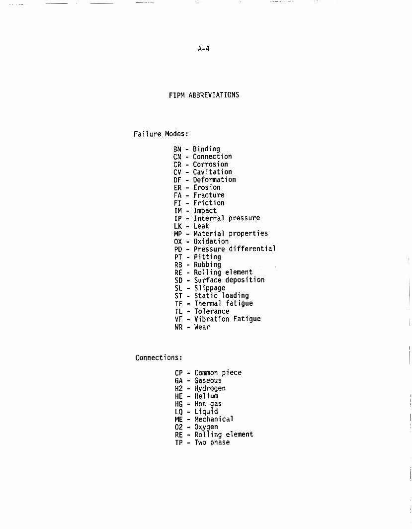
FIPM ABBREVIATIONS
Failure Modes:
BN - Binding CN - Connection CR - Corrosion CV - Cavitation DF - Deformation ER - Erosion FA - Fracture FI - Friction IM - Impact IP - Internal pressure LK - Leak MP - Material properties OX - Oxidation PD - Pressure differential PT - Pitting RB - Rubbing RE - Rolling element SD - Surface deposition SL - Slippage ST - Static loading TF - Thermal fatigue TL - Tolerance VF - Vibration Fatigue W R - Wear
Connections :
CP - Common piece GA - Gaseous H2 - Hydrogen HE - Helium HG - Hot gas LQ - Liquid ME - Mechanical 02 - Oxygen RE - Rolling element TP - Two phase

ALLOWABLE F I P M VALUES
R e f e r e n c e S o u r c e s :
AEROJ ET BATTELLE MARTIN MARIETTA NASA HDQ NASA MSFC PRATT & WHITNEY ROCKETDYNE
F a i l u r e M o d e s :
CR OX - CORROSION: O X I D A T I O N D F I M - DEFORMATION: IMPACT D F I P - DEFORMATION: INTERNAL PRESSURE D F S T - DEFORMATION: S T A T I C LOADING D F SD - DEFORMATION: SURFACE DEPOSITION FA I M - FRACTURE: IMPACT FA I P - FRACTURE: INTERNAL PRESSURE FA S T - FRACTURE: S T A T I C LOADING FA TF - FRACTURE: THERMAL FATIGUE FA VF - FRACTURE: V I B R A T I O N FATIGUE FI BN - FRICTION: BINDING F I S L - F R I C T I O N : SLIPPAGE L K CN - LEAK: CONNECTION L K ER - LEAK: EROSION L K FA - LEAK: FRACTURE L K PD - LEAK: PRESSURE D I F F E R E N T I A L L K T L - LEAK: TOLERANCE MP SD - MATERIAL PROPERTIES: SURFACE D E P O S I T I O N WR CV - WEAR: C A V I T A T I O N WR ER - WEAR: EROSION WR PT - WEAR: P I T T I N G WR RE - WEAR: ROLLING ELEMENTS WR RB - WEAR: RUBBING

ALLOWABLE FIPM VALUES (CONTINUED)
C o n n e c t i o n s :
GA H 2 - GASEOUS: HYDROGEN GA HE - GASEOUS: HELIUM GA HG - GASEOUS: HOT GAS GA 02 - GASEOUS: OXYGEN LQ H 2 - L I Q U I D : HYDROGEN LQ HE - L I Q U I D : HELIUM LQ 02 - L I Q U I D : OXYGEN ME -- - MECHANICAL ME CP - MECHANICAL: COMMON P I E C E ME RE - MECHANICAL: ROLLING ELEMENT T P H 2 - TWO PHASE: HYDROGEN T P HE - TWO PHASE: H E L I U M T P 02 - TWO PHASE: OXYGEN
S i g n a l s :
ACOUSTIC ELECTRICAL FLOW PRESSURE RPM THERMAL TORQUE V I BRAT I ON WORN PARTICLES
P a r a m e t e r s :
AMPLITUDE FREQUENCY PHASE

A-7
REQUIRED DATA F I E L D S
D o m a i n REFERENCES:
DOCUMENT TITLE [REPORT OR DOCUMENT TITLE: 1 * DOCUMENT-SOURCE [ORIGINATING ORGANIZATION : ] DOCUMENT-DATE - [DOCUMENT DATE (DD-MMM-YYYY) : ]
D o m a i n SYSTEMS :
SYSTEM [SYSTEM: 1 I T E M 1 [CONSTITUENT ROCKETDYNE FMEA ITEMS: 1) 3 SYSTEM-NAME [SYSTEM NAME: ]
REFERENCE1 [REFERENCE DOCUMENTS: 1) ]
D o m a i n MODULES:
SYSTEM [SYSTEM: ] MODULE [MODULE: ] SYSTEM-MODULE - NAME [MODULE NAME: ]
D o m a i n FAILUREMODES:
SOURCE SYSTEM MODULE FA1 LURE MODE SUBMODE ACCOMPLYCE - SYSTEM - MODULE.
[SOURCE SYSTEM AND MODULE: ] [FAILURE MODE AND SUBMODE: ] [ACCOMPLICE SYSTEM AND MODULE: ]
D o m a i n CONNECTIONS:
SYSTEM MODULE - A [SYSTEM AND MODULE A: 3 CONNECTION [CONNECTION (TYPE AND Q U A L I F I E R ) : ] UNANTICIPATED CONNECTION [UNANTICIPATED CONNECTION (T OR F) : 3 s Y ST EM-MO D u L E-B - [SYSTEM AND MODULE B: ]
The i t e m i n b rackets i s the da ta p r o m p t as i t appears on t he i npu t f o r m .
*
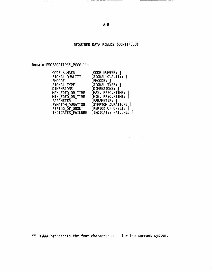
A - a
REQUIRED DATA F I E L D S (CONTINUED)
D o m a i n PROPAGATIONS-@### **:
CODE NUMBER S I G N A L Q U A L I T Y
S I G N A L TYPE
MAX FREQ OR T I M E
FMCODE-
D I MEN S ~ O N S
MI N-FR EQ-OR~T I ME PARAMETER
I NDICATES~FAI LURE
SYMPTOM DURATION PERIOD OF ONSET
[CODE NUMBER: ] [SIGNAL QUALITY: ] [FMCODE: ] [SIGNAL TYPE: ] [DIMENSIONS : ] [MAX. FREQ./TIME: ] [MIN. FREQ./TIME: ] [PARAMETER: 1 [SYMPTOM DURATION: 3 [PERIOD OF ONSET: 3 [ I N D I C A T E S FAILURE: ]
@### represents the four-character code f o r t he cur ren t s y s t e m . **

A-9
DATA F I E L D S WHICH CANNOT BE M O D I F I E D
D o m a i n REFERENCES:
DOCUMENT T I T L E DOCUMENT-SOURCE [ORIGINATING ORGANIZATION : ] DOCUMENT-DATE -
[REPORT OR DOCUMENT T I T L E : ] * [DOCUMENT DATE (DD-MMM-YYYY) : ]
D o m a i n SYSTEMS:
SYSTEM [SYSTEM: ]
D o m a i n MODULES:
SYSTEM [SYSTEM: 3 MODULE [MODULE: ]
D o m a i n FAILUREMODES:
SOURCE SYSTEM MODULE F A 1 LURE MODE SUBMODE ACCOMPLTCE-SYSTEM-MODULE
[SOURCE SYSTEM AND MODULE: ] [ F A I L U R E MODE AND SUBMODE: ] [ACCOMPLICE SYSTEM AND MODULE: ]
D o m a i n CONNECTIONS:
Al l Fields
D o m a i n PROPAGATIONS-@### **:
CODE NUMBER [CODE NUMBER: ] FMCODE [FMCODE: ] S I G N A L TYPE [S IGNAL TYPE: ] PARAMETER [PARAMETER: ]
T h e i t e m i n brackets i s t he da ta p r o m p t as i t appears on t he i n p u t f o r m . @### represents t h e four-character code f o r t h e c u r r e n t s y s t e m .
*
**

A-10
FORM FOR GENERATING F A I L U R E INFORMATION PROPAGATION DATA
SIGNAL-QUALIN: 0 1 2 3 4 5 VERY WEAK MODERATE STRONG
FMCODE: ---- ---- -- -- ---- ---- FAILURE MODE SYSTEM MODULE NO FAILURE CAILURE SYSTEM MODULE NO
CODE ==== SOURCE MODULE ==== MODE SUBMODE = a = ACCOMPLICE MODULE ===
SIGNAL-TYPE: FLOW TORQUE RPM PRESSURE VIBRATION ACOUSTIC THERMAL ELECTRICAL WORN PARTICLES
DIMENSIONS: 1 2 3
MIN-FREO-OR-TIME: 1 E
PARAMETER FREQUENCY AMPLITUDE PHASE
PERIOD-OF-ONSET: 1 E
INDICATES-FAILURE: T or F
COMMENTl:
(MAX BO CHAR.)
COMMENT2
(MAX 80 CHAR.)

A-11
RULES USED FOR SSME FIPMs
MODULE SELECTION
There are no f i x e d r u l e s f o r spec i fy ing t h e l e v e l o f t h e modules se lected f o r t h e FIPM. I n some cases, i n d i v i d u a l p iece p a r t s from a p a r t s l i s t may be used. I n o ther cases, an assembly o f p a r t s which has a s i n g l e func t ion and s t r a i g h t forward f a i l u r e modes may be selected. I n a l l cases, t h e dec is ion w i l l be based on t h e f u n c t i o n o f t h e p a r t o r par ts . Each f u n c t i o n w i l l be represented by a separate module.
MODULE NUMBERING SCHEME
A l l modules o f t h e FIPM s h a l l be uniquely i d e n t i f i e d by t h e combination o f a four-character system code and a f o u r - d i g i t number.
Example: B400 0010
COMMON-PIECE CONNECTIONS
When a s i n g l e p a r t serves m u l t i p l e funct ions, each f u n c t i o n w i l l be represented as a d i s t i n c t module. These modules w i l l be connected by ME CP (MECHANICAL: COMMON PIECE) connections. The modules w i l l be named as fo l lows:
PART NAME -- FUNCTION
Example: SHAFT ASSEMBLY SHAFT ASSEMBLY -- LUBRICATION PASSAGE
FASTENERS
Fasteners are represented i n t h e FIPM as a s i n g l e module w i t h a ME -- (MECHANICAL) connection t o each o f t h e p a r t s being jo ined. No d i r e c t connection w i l l be shown between t h e p a r t s being jo ined.
Fasteners which j o i n modules from two adjacent systems (e.g., B400 and B600) w i l l be associated w i t h t h e upstream system.
Example: The fasteners which a t tach t h e LPOTP Pump Discharge Duct (module o f system B800) t o t h e Main Pump Housing -- I n l e t Mani fo ld (module o f system 8400) w i l l be a module o f system B800.
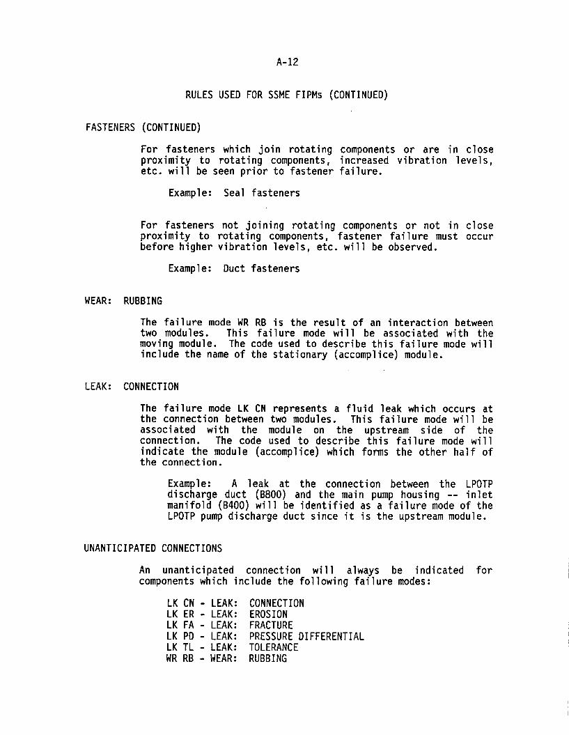
A- 12
RULES USED FOR SSME FIPMs (CONTINUED)
FASTENERS (CONTINUED)
For fasteners which join rotating components or are in close proximity to rotating components, increased vibration levels, etc. will be seen prior to fastener failure.
Example: Seal fasteners
For fasteners not joining rotating components or not in close proximity to rotating components, fastener failure must occur before higher vibration levels, etc. will be observed.
Example: Duct fasteners
WEAR: RUBBING
The failure mode WR RB is the result o f an interaction between two modules. This failure mode will be associated with the moving module. The code used to describe this failure mode will include the name of the stationary (accomplice) module.
LEAK: CONNECTION
The failure mode LK CN represents a fluid leak which occurs at the connection between two modules. This failure mode will be associated with the module on the upstream side of the connection. The code used to describe this failure mode will indicate the module (accomplice) which forms the other half of the connection.
Example: A leak at the connection between the LPOTP discharge duct (B800) and the main pump housing -- inlet manifold (B400) will be identified as a failure mode of the LPOTP pump discharge duct since it is the upstream module.
UNANTICIPATED CONNECTIONS
An unanticipated connection will always be indicated for components which include the following failure modes:
LK CN - LEAK: CONNECTION LK ER - LEAK: EROSION LK FA - LEAK: FRACTURE LK PD - LEAK: PRESSURE DIFFERENTIAL LK TL - LEAK: TOLERANCE W R RB - WEAR: RUBBING

A- 13
RULES USED FOR SSME FIPMs (CONTINUED)
DUCTS
A duct will be defined as being a module of the upstream system to which it is attached.
Examples: LPFTP pump discharge duct is a module in the low-pressure fuel turbopump FIPM. High-pressure fuel duct is a module in the high-pressure fuel turbopump FIPM.
VALVES
A valve will be defined as being a module of the downstream system into which the flow is being controlled or modulated by the valve.
Examples: The main oxidizer valve (MOV) is a module in the main injector FIPM. The anti-flood valve (AFV) is a module in the heat exchanger FIPM.
EXTERNAL CONNECTIONS
Any connections which exist between FIPM systems will be represented in the model of both systems.
Example: The connection between the LPOTP discharge duct (system B800) and the main pump housing -- inlet manifold (system B400) will be represented in the FIPMs for both systems.
The external connections will be appropriately identified on the FIPM drawing. Failure modes will not be identified for the module from the adjacent system.
When generating failure information propagations, the signals will be propagated to the external connections. However, the information flow will not proceed through the adjacent system.
SEALS
For seals between a moving and a stationary part, the seal function will be associated with the stationary part.

A-14
RULES USED FOR SSME FIPMs (CONTINUED)
ALLOWABLE VALUES
The allowable values used for the SSME FIPMSs should be viewed as a dynamic set o f parameters which can and should evolve as new models are developed. It is quite likely that models of additional engine components would. require new connections and new failure modes.
Example: LQ N2 - LIQUID: NITROGEN

A - 1 5
GENERIC F A I L U R E MODE DESCRIPTIONS
CR OX - LOSS OF SURFACE MATERIAL THROUGH THE CHEMICAL PROCESS OF O X I D A T I O N
DF I M - ALTERATION OF PHYSICAL DIMENSIONS DUE TO IMPACT OF DEBRIS FROM UPSTREAM FAILURES OR CONTAMINATION
DF I P - ALTERATION OF PHYSICAL DIMENSIONS DUE TO EXCESSIVE PRESSURE LOAD I NG
DF S T - ALTERATION OF PHYSICAL DIMENSIONS DUE TO EXCESSIVE S T A T I C LOADING
DF SD - ALTERATION OF PHYSICAL DIMENSIONS DUE TO ACCUMULATION OF PARTICULATE MATTER
FA I M - CRACKING DUE TO IMPACT OF DEBRIS FROM UPSTREAM F A I L U R E S OR CONTAMINATION
FA I P - CRACKING DUE TO EXCESSIVE PRESSURE LOADING
FA S T - CRACKING DUE TO EXCESSIVE S T A T I C LOADING
FA T F - CRACKING DUE TO EXCESSIVE CYCLICAL AND TRANSIENT THERMAL LOADING
FA V F - CRACKING DUE TO EXCESSIVE C Y C L I C A L AND TRANSIENT MECHANICAL LOAD I NG
F I BN - TIGHTENING DUE TO UNEXPECTED LOADING OR DIMENSIONAL GROWTH DURING OPERAT I ON
F I S L - LOOSENING DUE TO EXCESSIVE CYCLICAL OR TRANSIENT LOADING (MECHANICAL OR THERMAL)
L K CN - LEAKAGE DUE TO I N S U F F I C I E N T MECHANICAL COUPLING WITH ADJACENT COMPONENT ( 1
L K ER - LEAKAGE DUE TO COMPONENT BURN THROUGH CAUSED BY EXCESSIVE EROSION
L K F A - LEAKAGE DUE TO CRACK PROPAGATION FROM FRACTURE F A I L U R E
I-K PD - LEAKAGE DUE TO LOSS OF PRESSURANT
L K TL - LEAKAGE DUE TO DIMENSIONAL CHANGES CAUSED BY WEAR
MP SD - ALTERATION OF THE PHYSICAL PROPERTIES OF THE MATERIAL DUE TO ACCUMULATION OF PARTICULATE MATTER

A - 1 6
GENERIC F A I L U R E MODE DESCRIPTIONS (CONTINUED)
WR CV - ABRASION DUE TO EXCESSIVE PRESSURE O S C I L L A T I O N S CAUSED BY C A V I T A T I O N
WR ER - ABRASION DUE TO HOT GASES AND PARTICULATE MATTER I N FLOW
WR P T - LOSS OF SURFACE MATERIAL DUE TO EXCESSIVE C Y C L I C A L AND TRANSIENT MECHANICAL LOADING
WR RE - ABRASION DUE TO CONTACT FORCES BETWEEN ROLLING ELEMENTS
WR RB - ABRASION DUE TO MECHANICAL CONTACT BETWEEN COMPONENTS W I T H R E L A T I V E MOTION ( WITH 1

APPENDIX B
SSME F I P M DRAWINGS
(SEE SEPARATE VOLUME OF T H I S REPORT)

APPENDIX C
EXCERPT FROM "HIGH-PRESSURE OXYGEN TURBOPUMP BEARING CAGE S T A B I L I T Y A N A L Y S I S "
REPORT TO NASA MSFC BY BATTELLE COLUMBUS D I V I S I O N

c- 1
SUMMARY AND CONCLUSIONS
Combinations of operating conditions and cage dimensions were identified that can cause the cage of the HPOTP turbine-end bearings to be unstable. Furthermore, the high accelerations associated with the instabilities can be expected to cause forces sufficient to fail the cage (depending upon the actual strength of the cage under operating conditions). The forces on the cage developed under normal (stable) operating conditions were found to be tolerable. Therefore, maintaining stable operation of the cage appears to be important in successful operation of the HPOTP bearings.
Cage stability was found to be particularly sensitive to the cage-race clearance, cage balance, and the lubricant film thickness between the balls and races (as it affects the ball-race traction). diametral clearances larger than 0.25 mn (0.01 in.) promote cage instabilities. In contrast, cage stability was found to be insensitive to ball-pocket clearance. Since small cage unbalances were predicted to cause instabilities,
Cage-race
the cages should be carefully balanced to minimize instability problems. Depletion of lubricant film thicknesses between the balls and races cause cage instability problems by increasing the ball-race traction, which underlines the importance o f maintaining adequate lubrication for successful long-term bearing life.
As a result of the study, several sensitive parameters affecting bearing dynamics were clearly identified. the bearings to minimize the likelihood o f cage instability should enhance cage stability and associated bearing reliability.
Therefore, modifications to
RECOMMENDATIONS
Based on the analyses, the following specific recommendations are made to minimize cage instability and its associated effects on bearing degredation.
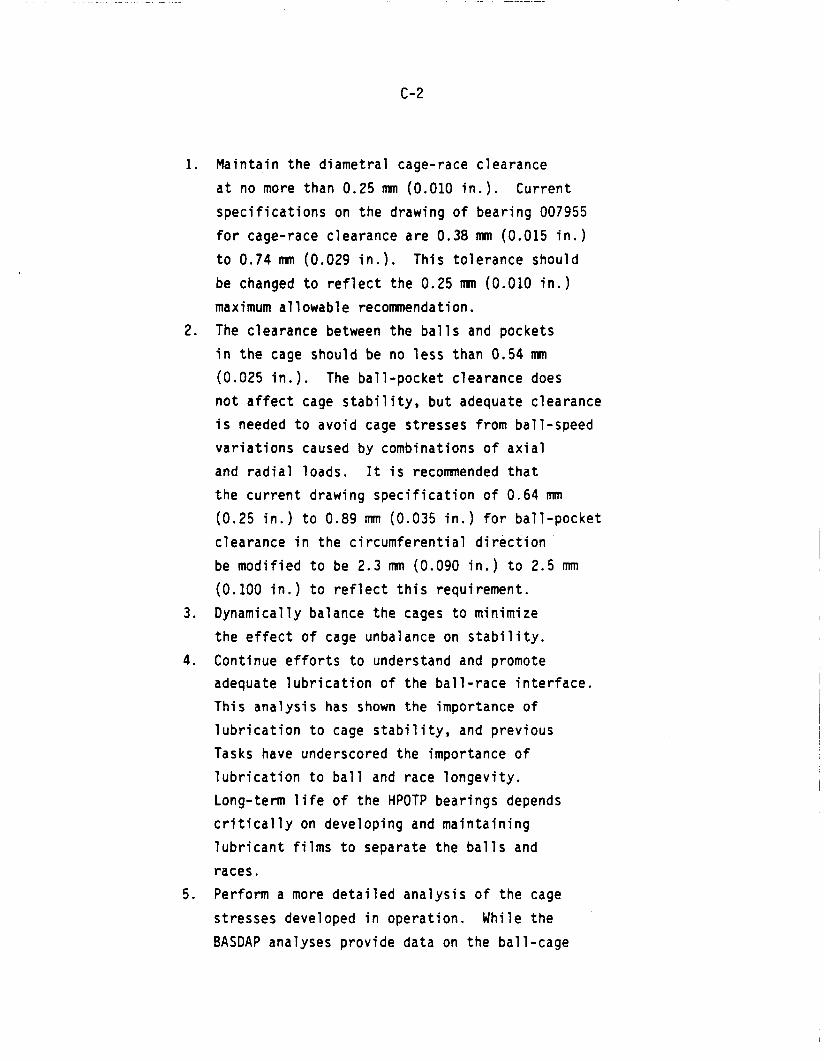
c-2
1. Maintain the diametral cage-race clearance at no more than 0.25 mm (0.010 in.). specifications on the drawing of bearing 007955 for cage-race clearance are 0.38 mm (0.015 in.) to 0.74 mn (0.029 in.). be changed to reflect the 0.25 mm (0.010 in.) maximum allowable recommendation. The clearance between the balls and pockets in the cage should be no less than 0.54 m (0.025 in.). not affect cage stability, but adequate clearance is needed to avoid cage stresses from ball-speed variations caused by combinations of axial and radial loads. It is recomnended that the current drawing specification of 0.64 mm (0.25 in.) to 0.89 mm (0.035 in.) for ball-pocket clearance in the circumferential direction be modified to be 2.3 m (0.090 in.) to 2.5 mm (0.100 in.) to reflect this requirement. Dynamically balance the cages to minimize the effect of cage unbalance on stability.
4. Continue efforts to understand and promote adequate lubrication of the ball-race interface. This analysis has shown the importance o f
lubrication to cage stability, and previous Tasks have underscored the importance of lubrication to ball and race longevity. Long-term life of the HPOTP bearings depends critically on developing and maintaining lubricant films to separate the balls and races. Perform a more detailed analysis of the cage stresses developed in operation. While the BASDAP analyses provide data on the ball-cage
Current
This tolerance should
2.
The ball-pocket clearance does
3 .
5 .

c-3
forces, the actual stresses developed r e s u l t from a combination o f these forces w i t h the cage geometry and cons t ra in t s by the ou ter (gu id ing) race. o n l y an approximate considerat ion o f these stresses. Schedule a review meeting t o be at tended by NASA, Rocketdyne, and B a t t e l l e personnel t o review the imp l i ca t i ons o f the f i nd ings i n t h i s Task and determine what p r a c t i c a l steps can be taken t o minimize p o t e n t i a l cage i n s t a b i l i t y problems.
The cu r ren t study permi t ted
6.

c-4
(This page intentionally bl.ank)

APPENDIX D
STBE AND STME DIAGNOSTIC REQUIREMENTS DOCUMENT

D-1
DIAGNOSTIC MONITORING SYSTEM REQUIREMENTS FOR THE
SPACE TRANSPORTATION BOOSTER AND MAIN ENGINES (STBE and STME)
General Discussion
A diagnostic monitoring system shall be included as a key item in the design of both the Space Transportation Booster Engine (STBE) and the Space Transportation Main Engine (STME). The purpose of this system will be to acquire data relative to the performance and overall condition of the engine and its associated components. The data obtained from the diagnostic system will be used to characterize nominal engine operating conditions, quantify limits on key engine parameters, identify degradations in engine performance, warn of impending failures, and provide input on maintenance requirements. The information collected by the system may be processed and used on a real-time basis during engine operation, recorded for use in post- test or post-flight analyses, or utilized in a mode combining both real-time and post-operation processing. Anticipated benefits from the diagnostic system include improved identification and warning of anomalous engine conditions, extended intervals between engine inspections, and increased data on which to base maintenance decisions. To satisfy all of the objectives outlined above, it will be necessary to consider the diagnostic system as an integral part of the engine design and development program.
The diagnostic monitoring system for the STBE and STME will include all elements necessary t o fulfill the objectives discussed previously including appropriate sensors or procedures, signal conditioning and formatting devices, means for transmission and recording of collected data, on-board or ground-based processors, respective decision making criteria, and associated computational algorithms. It is recognized that the requirements for safety versus maintenance diagnostics vary widely in terms of speed, reliability, number of parameters, etc. The monitoring system must include provisions to accommodate this situation while fully

D-2
exploiting the joint data elements needed for both roles. The diagnostic system design will make maximum use of automated techniques and procedures where feasible to improve the overall quality and consistency of the engine data. However, the overall diagnostic system concept should also consider other appropriate techniques for determining engine condition and maintenance requirements such as human or human-assisted inspections, tests, or analyses. The respective roles of in-flight and ground-based processing and analysis must also be carefully evaluated in the design of any prospective engine monitoring system. The principal criteria on which diagnostic system trades will be based is flight safety but cost factors will also play a role in determining the final configuration and mode of operation.
The diagnostic monitoring system, in addition to providing specific data relative to the engine and its components, shall be considered in the broader context of the overall maintenance and maintainability program for both the STBE and STME. The prior experience with reusable liquid rocket engines has shown that maintenance and maintainability are major factors in the overall operational costs attributable to the engine. Integrated planning in this important area may yield significant cost improvements for new engine designs. The diagnostic system interactions with and contributions to the maintenance/maintainabi 1 ity program must be evaluated during the formulation of the STBE and STME designs.
Diagnostic System Considerations During Engine Design
The diagnostic monitoring system will introduce four major considerations to the overall design of the STBE and STME. The first is the selection of the number and type of sensors required to implement the desired diagnostic strategy. This decision is strongly related to the overall level of confidence required in the diagnostic measurements and the issue of sensor reliability in the operating environment associated with large, high-performance, liquid rocket engines. The second is the incorporation of adequate provisions for sensor or inspection access to the required measurement locations. This access may or may not be intrusive to

0-3
the component being monitored depending on the particular sensor selected for the application. The third is the evaluation of the environmental conditions imposed on the sensors during engine operation. This issue must be addressed so that adequate protection or isolation can be provided where necessary. The final consideration is the computational capacity required in the engine controller to implement the selected diagnostic and control approach. In view of the items mentioned above, the diagnostic monitoring system must be considered from the very beginning of the engine design and development cycle.
Key Diagnostic Parameters
The parameters of particular importance in assessing engine condition and maintenance requirements are generally associated with the turbomachinery, combustion devices, propel lant/coolant flows, and actuator/valve positions. Specific parameters of interest include but are not limited to turbopump shaft speeds, turbopump torque levels, turbine outlet values, turbopump bearing condition, turbine blade stresses, main combustion chamber conditions, preburner chamber values, total oxidizer and fuel flow rates, flow rates associated with coolant or purge fluids, position of the main oxidizer and fuel valves, and information relative to the position or proper functioning of other critical valves and actuators. Another area of increasing interest pertains to new or novel approaches to detect and locate leaks in the various engine components. The fundamental physical measurements required to obtain the information described above include temperature, pressure, strain, acceleration, acoustic, and optical. The first four measurement types represent conventional sensors widely used in rocket engines and other similar applications. Acoustic and optical sensors are newer approaches but should be considered in view of their overall potential. The design of the diagnostic monitoring system also should carefully consider the sampling rate and signal format associated with the measurements. Current systems tend to use RMS (Root Mean Square) values sampled at discrete intervals on the order of 20 milliseconds. This type of monitoring eliminates the spectral content associated with the raw

D-4
signal. Careful consideration should be given to systems which can process the entire sensor output spectrum for at . least selected measurement parameters.
Ground-Test Versus F1 i g h t Diagnostics
The diagnostic system shall be required to collect appropriate engine data in both the ground-test and flight environments. The requirements for the engine monitoring system will differ slightly in these two cases even though the basic goals o f safe and efficient operations remain the same. The minimum diagnostic system will consist of those elements necessary to fulfill the flight monitoring and control functions as initially defined by the contractor. However, it is recognized that information obtained during developmental, test-stand firings will form the foundation for the overall understanding of the engine and its operating characteristics. This fundamental role may impose additional requirements for ground-test diagnostic data above and beyond those needed during actual flight operations. The proposed monitoring system. must consider the implications of this situation and provide the flexibility to accommodate additional measurements without major modifications to the engine hardware. Provisions should at least be made in the basic design for any access ports or mounting surfaces which may be required to support the various sensors or test procedures used during engine characterization. Requirements for additional test site facilities or equipment to support the ground-test diagnostic measurements should be specified also.
In-F1 i g h t Versus Post-F1 i g h t Processing and Analysis
The diagnostic system design shall address the relative need for real-time processing and analysis of engine data during flight. Information needed to assess engine condition, operating trends, and control responses must be available on a real time or near real time basis to satisfy safety considerations. Additional data pertaining to required maintenance actions which do not affect the current mission may be recorded for later review and

D-5
analysis. The monitoring system will provide the capability to handle both types of data and direct the respective information streams to the appropriate storage or processing devices. The information required for real-time monitoring and control of the engine may be processed and analyzed in several ways. The actual option used will depend on the selected engine control scheme and the relative role of the diagnostic system within that scheme. In all cases, the information from the various sensors comprising the on-board monitoring system will be collected, preprocessed, and formatted by the engine controller. Three potential sites exist at which the diagnostic data may undergo additional processing/analysis. The information may be transmitted to the ground for computer or human analysis, passed to the vehicle flight computers for processing and subsequent action, or analyzed directly by the engine controller in a self-contained mode of operation. The diagnostic system may use any, all, or some combination of these approaches to satisfy the in-flight monitoring requirements.
Contractor Implementation Plan
The prospective STBE and STME contractors shall include the diagnostic monitoring system as a required element in the preliminary engine design phase. The contractor must describe the proposed diagnostic system in sufficient detail to demonstrate that the concept meets all of the
overall system objectives as outlined herein. The analyses and trades conducted during formulation o f the proposed concept will also be discussed to demonstrate the rationale associated with selection of the major system elements or features. All interfaces between the diagnostic system and the engine or vehicle will be specified. The diagnostic system requirements associated with other engine or vehicle systems such as power, data storage, telemetry, etc. will be identified to the extent possible. The role of the diagnostic monitoring system in the maintenance/maintainability program for the respective engine will be described and any major contributions to improved maintenance/maintainability will be outlined. The contractor shall specifically discuss the overall approach to ground-test and flight diagnostics and define any unique test site requirements associated with the

0-6
selected engine monitoring system. The contractor also will discuss the preferred approach for the processing and analysis of in-flight engine data. The computational requirements imposed by the selected concept will be outlined with specific reference to engine, vehicle, and ground-based processors. The post-flight maintenance evaluation will be described to complete the definition of the overall diagnostic system and to allow assessment of the interactions between in-flight and post-fl ight monitoring requirements.

APPENDIX E
M A I N ENGINE COST/OPERATIONS MODEL L O G I C DIAGRAMS

E- 1
OPS PROCESSING: I PRE-MISSION
START 9 FOR EACH
ENGINE
FOR EACH COMPONENT Q-
QN M I SS I NG
L
REPLACE MISSING
T MISSION
I
0 END

E-2
CREATE THE ENGINE OR COMPONENT
I-1
USE PART FROM INVENTORY
START 7
ACCEPTANCE TEST OR
[ INCREASE MTBR I EXPOSURE

E-3
OPS PROCESSING: POST-M I s s 1 ow
WISSIOM
R E W E AN0 DESTROY ENGINE CR ITEQ IP Ne". , ,
EVENT'
( COMPONENT ;Jd'Tn?pRcw )- c e-= WINTEYANCE
SENO TO Md[YTENPNCE
SENO TO Md[YTENPNCE
CONSUME CCWONE NT

E-4
START P FOR EACH
COMPONENT
+
REMOVE AND CONSUM
COMPONENT
REPLACE THE COMPONENT
I BRING COMPONENT TO LIKE-NEW EXCEPT L L 1
ASSEMBLE 1 ~ ENGINE I ACCEPTANCE
TEST THE ENGINE
1 INCREASE MTBR EXPOSURE FOR
ALL COMPONENTS
A00 ENGINE r-3 !WENTORY
L&l

E-5
COMPONENT I MAINTENANCE
START 7 EVENT? Ql
+I MINTENANCE
I,
00 MAINTENANCE FOR ALL LLs
GREEN RUN COMPONENT
1 INCREASE MTBR EXPOSURE ON
THAT COMPONENT

E-6
SELECT S A M ENGINE FOR
F/C RUNNING
I I
F/C PROCESSING: START (7
MISS I NG C W O N E N T

I
E-7
1fRRlWlf T H I S 1
t I

E-8


![La educación de masas, una encrucijada en el …a6d...185.LXIII LA EDUCACION DE MASAS, UNA ENCRUCIJADA EN EL MUNDO ACTUAL [89] 89 te, digamos también que la comprensión histó-rica](https://img.dokumen.tips/doc/110x75/5f4d20680a15c72b655f5d84/la-educacin-de-masas-una-encrucijada-en-el-a6d-185lxiii-la-educacion-de-masas.jpg)