Embed Size (px)
Citation preview
®
87V Ex True-rms Multimeter
Users Manual
PN 2518115 December 2005 2005 Fluke Corporation. All rights reserved. Printed in USA All product names are trademarks of their respective companies.
LIMITED WARRANTY AND LIMITATION OF LIABILITY
Each Fluke product is warranted to be free from defects in material and workmanship under normal use and service. The warranty period is one year and begins on the date of shipment. Parts, product repairs, and services are warranted for 90 days. This warranty extends only to the original buyer or end-user customer of a Fluke authorized reseller, and does not apply to fuses, disposable batteries, or to any product which, in Fluke's opinion, has been misused, altered, neglected, contaminated, or damaged by accident or abnormal conditions of operation or handling. Fluke warrants that software will operate substantially in accordance with its functional specifications for 90 days and that it has been properly recorded on non-defective media. Fluke does not warrant that software will be error free or operate without interruption.
Fluke authorized resellers shall extend this warranty on new and unused products to end-user customers only but have no authority to extend a greater or different warranty on behalf of Fluke. Warranty support is available only if product is purchased through a Fluke authorized sales outlet or Buyer has paid the applicable international price. Fluke reserves the right to invoice Buyer for importation costs of repair/replacement parts when product purchased in one country is submitted for repair in another country.
Fluke's warranty obligation is limited, at Fluke's option, to refund of the purchase price, free of charge repair, or replacement of a defective product which is returned to a Fluke authorized service center within the warranty period.
To obtain warranty service, contact your nearest Fluke authorized service center to obtain return authorization information, then send the product to that service center, with a description of the difficulty, postage and insurance prepaid (FOB Destination). Fluke assumes no risk for damage in transit. Following warranty repair, the product will be returned to Buyer, transportation prepaid (FOB Destination). If Fluke determines that failure was caused by neglect, misuse, contamination, alteration, accident, or abnormal condition of operation or handling, including overvoltage failures caused by use outside the product’s specified rating, or normal wear and tear of mechanical components, Fluke will provide an estimate of repair costs and obtain authorization before commencing the work. Following repair, the product will be returned to the Buyer transportation prepaid and the Buyer will be billed for the repair and return transportation charges (FOB Shipping Point).
THIS WARRANTY IS BUYER'S SOLE AND EXCLUSIVE REMEDY AND IS IN LIEU OF ALL OTHER WARRANTIES, EXPRESS OR IMPLIED, INCLUDING BUT NOT LIMITED TO ANY IMPLIED WARRANTY OF MERCHANTABILITY OR FITNESS FOR A PARTICULAR PURPOSE. FLUKE SHALL NOT BE LIABLE FOR ANY SPECIAL, INDIRECT, INCIDENTAL, OR CONSEQUENTIAL DAMAGES OR LOSSES, INCLUDING LOSS OF DATA, ARISING FROM ANY CAUSE OR THEORY.
Since some countries or states do not allow limitation of the term of an implied warranty, or exclusion or limitation of incidental or consequential damages, the limitations and exclusions of this warranty may not apply to every buyer. If any provision of this Warranty is held invalid or unenforceable by a court or other decision-maker of competent jurisdiction, such holding will not affect the validity or enforceability of any other provision.
Fluke Corporation P.O. Box 9090 Everett, WA 98206-9090 U.S.A.
Fluke Europe B.V. P.O. Box 1186 5602 BD Eindhoven The Netherlands
11/99
i
Table of Contents
Title Page Introduction.....................................................................................................................1 Contacting Fluke ............................................................................................................1 General Safety Information.............................................................................................2 ATEX Safety Information................................................................................................2
Errors and Load Restrictions .....................................................................................5 Ex-Certification Data..................................................................................................6
The Meter's Features .....................................................................................................8 Power-Up Options .....................................................................................................15 Automatic Power-Off .................................................................................................15 Input Alert Feature ..................................................................................................15
Making Measurements ...................................................................................................15 Measuring AC and DC Voltage..................................................................................15 Zero Input Behavior of True-rms Meters....................................................................17 Low Pass Filter ..........................................................................................................17 Measuring Temperature ............................................................................................18 Testing for Continuity.................................................................................................18 Measuring Resistance ...............................................................................................20 Using Conductance for High Resistance or Leakage Tests.......................................22 Measuring Capacitance .............................................................................................23 Testing Diodes...........................................................................................................24 Measuring AC or DC Current.....................................................................................26 Measuring Frequency................................................................................................29
87V Ex Users Manual
ii
Measuring Duty Cycle ............................................................................................... 31 Determining Pulse Width........................................................................................... 32
Bar Graph ...................................................................................................................... 32 Zoom Mode (Power Up Option Only) ........................................................................ 33 Uses for the Zoom Mode........................................................................................... 33
HiRes Mode ................................................................................................................... 33 MIN MAX Recording Mode ............................................................................................ 34 Smooth Feature (Power Up Option Only) ...................................................................... 34 AutoHOLD Mode........................................................................................................... 36 Relative Mode................................................................................................................ 36 Maintenance .................................................................................................................. 37
General Maintenance................................................................................................ 37 Fuse Test .................................................................................................................. 37 Replacing the Battery................................................................................................ 38 Replacing the Fuses ................................................................................................. 39
Service and Parts........................................................................................................... 40 General Specifications ................................................................................................... 45 Detailed Specifications................................................................................................... 46
AC Voltage Function ................................................................................................. 46 DC Voltage, Resistance, and Conductance Function ............................................... 47 Temperature ............................................................................................................. 48 Current Function ....................................................................................................... 49 Capacitance and Diode Function .............................................................................. 50 Frequency Counter ................................................................................................... 50 Frequency Counter Sensitivity and Trigger Levels.................................................... 51 Electrical Characteristics of the Terminals ................................................................ 52 MIN MAX Recording ................................................................................................. 53
iii
List of Tables
Table Title Page
1. Electrical Symbols ................................................................................................................. 7 2. Inputs..................................................................................................................................... 8 3. Rotary Switch Positions......................................................................................................... 9 4. Pushbuttons .......................................................................................................................... 10 5. Display Features.................................................................................................................... 13 6. Functions and Trigger Levels for Frequency Measurements................................................. 30 7. MIN MAX Functions............................................................................................................... 35 8. Approved Batteries ................................................................................................................ 39 9. Replacement Parts ................................................................................................................ 42 10. Specified Accessories ........................................................................................................... 44

87V Ex Users Manual
iv
v
List of Figures
Figure Title Page
1. Display Features.................................................................................................................... 13 2. Measuring AC and DC Voltage.............................................................................................. 16 3. Low Pass Filter ...................................................................................................................... 17 4. Testing for Continuity............................................................................................................. 19 5. Measuring Resistance ........................................................................................................... 21 6. Measuring Capacitance......................................................................................................... 23 7. Testing a Diode ..................................................................................................................... 25 8. Measuring Current................................................................................................................. 27 9. Components of Duty Cycle Measurements ........................................................................... 31 10. Testing the Current Fuses ..................................................................................................... 38 11. Battery and Fuse Replacement ............................................................................................. 41 12. Replaceable Parts ................................................................................................................. 43

87V Ex Users Manual
vi
1
True-rms Multimeter
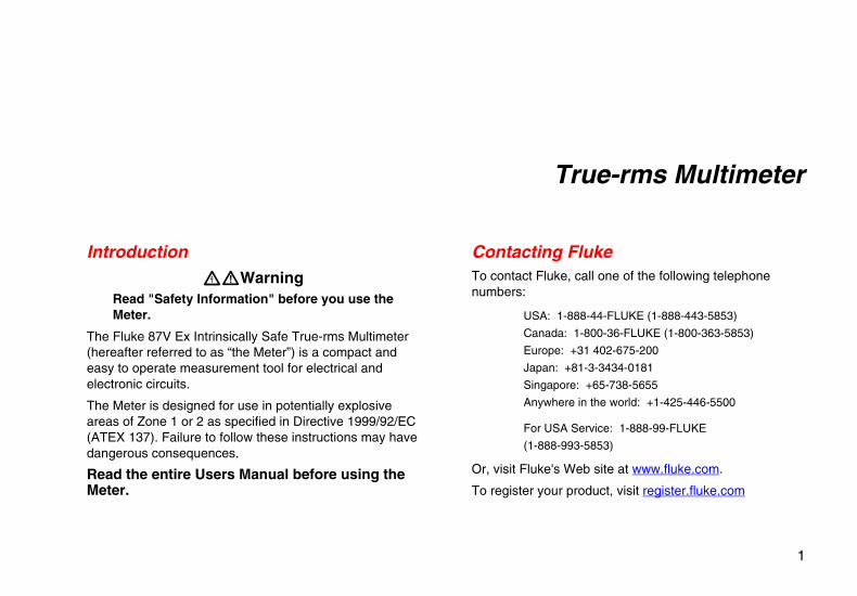
Introduction XWWarning
Read "Safety Information" before you use the Meter.
The Fluke 87V Ex Intrinsically Safe True-rms Multimeter (hereafter referred to as “the Meter”) is a compact and easy to operate measurement tool for electrical and electronic circuits.
The Meter is designed for use in potentially explosive areas of Zone 1 or 2 as specified in Directive 1999/92/EC (ATEX 137). Failure to follow these instructions may have dangerous consequences.
Read the entire Users Manual before using the Meter.
Contacting Fluke To contact Fluke, call one of the following telephone numbers:
USA: 1-888-44-FLUKE (1-888-443-5853)
Canada: 1-800-36-FLUKE (1-800-363-5853)
Europe: +31 402-675-200
Japan: +81-3-3434-0181
Singapore: +65-738-5655
Anywhere in the world: +1-425-446-5500
For USA Service: 1-888-99-FLUKE
(1-888-993-5853)
Or, visit Fluke's Web site at www.fluke.com.
To register your product, visit register.fluke.com
87V Ex Users Manual
2
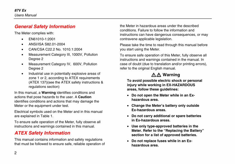
General Safety Information The Meter complies with:
• EN61010-1:2001 • ANSI/ISA S82.01-2004
• CAN/CSA C22.2 No. 1010.1:2004
• Measurement Category III, 1000V, Pollution Degree 2
• Measurement Category IV, 600V, Pollution Degree 2
• Industrial use in potentially explosive areas of zone 1 or 2, according to ATEX requirements (ATEX 137)(see the ATEX safety instructions & regulations section)
In this manual, a Warning identifies conditions and actions that pose hazards to the user. A Caution identifies conditions and actions that may damage the Meter or the equipment under test.
Electrical symbols used on the Meter and in this manual are explained in Table 1.
To ensure safe operation of the Meter, fully observe all instructions and warnings contained in this manual.
ATEX Safety Information This manual contains information and safety regulations that must be followed to ensure safe, reliable operation of
the Meter in hazardous areas under the described conditions. Failure to follow the information and instructions can have dangerous consequences, or may contravene applicable legislation.
Please take the time to read through this manual before you start using the Meter.
To ensure safe operation of this Meter, fully observe all instructions and warnings contained in the manual. In case of doubt (due to translation and/or printing errors), refer to the original English manual.
XW Warning To avoid possible electric shock or personal injury while working in EX-HAZARDOUS areas, follow these guidelines:
• Do not open the Meter while in an Ex-hazardous area.
• Change the Meter’s battery only outside Ex-hazardous areas.
• Do not carry additional or spare batteries in Ex-hazardous areas.
• Use only type-approved batteries in the Meter. Refer to the “Replacing the Battery” section for a list of approved batteries.
• Do not replace fuses while in an Ex-hazardous area.
True-rms Multimeter ATEX Safety Information
3
• Use only fuses approved for Ex-hazardous areas in this Meter. See the “Replacing the Fuses” section for a list of approved fuses.
• After using the Meter on a non-i.s. protected circuit, observe a 3-minute rest period before taking the Meter into an Ex-hazardous area.
• The Meter must be completely and securely fitted in the red holster while it is in an Ex-hazardous area.
• Do not open function buttons inside the Meter. Interference or damage to any of these elements removes the Ex-protection.
• Observe the tolerances or threshold values found in the “Specifications” section of this manual.
• Use only allowed accessories with this Meter in Ex-hazardous areas. See a listing of allowed Fluke accessories at www.Fluke.com.
• Avoid using the Meter in aggressive acidic or alkaline solutions.
• Do not use the Meter in zone 0.
• Never measure voltages greater than 65 volts in an Ex-hazardous area.
• Never measure currents greater than 5 amps while using the Meter in an Ex-hazardous area.
• Servicing not covered in this manual should be performed only by the manufacturer. Repair or service by others may void the ATEX certification of this Meter.
XWWarning To avoid possible electric shock or personal injury in ALL areas of operation, follow these guidelines:
• Use this Meter only as specified in this manual or the protection provided by the Meter might be impaired.
• See the “ATEX Safety Information” section for additional warnings on meter use in hazardous areas.
• Do not use the Meter if it is damaged. Before you use the Meter, inspect the case. Look for cracks or missing plastic. Pay particular attention to the insulation surrounding the connectors.
87V Ex Users Manual
4
• Ensure the battery door is closed and latched whenever operating the Meter.
• Replace the battery as soon as the battery indicator (M) appears. See “Replacing the Battery” section for instructions and a list of approved batteries.
• Remove test leads from the Meter before opening the battery door.
• Inspect the test leads for damaged insulation or exposed metal. Check the test leads for continuity. Replace damaged leads before using the Meter.
• Do not apply more than the rated voltage, as marked on the Meter, between the terminals or between any terminal and earth ground.
• Use caution when working with voltages above 30 V ac rms, 42 V ac peak, or 60 V dc. These voltages pose a shock hazard.
• Use only the replacement fuses specified in this Users Manual. See “Replacing the Fuses” section for instructions and a list of approved fuses.
• Use the proper terminals, function, and range for measurements.
• Avoid working alone. • When measuring current, turn off circuit
power before connecting the Meter to the circuit. Remember to place the Meter in series with the circuit.
• When making electrical connections, connect the common test lead before connecting the live test lead; when disconnecting, disconnect the live test lead before disconnecting the common test lead.
• Do not use the Meter if it operates abnormally. Protection may be impaired. When in doubt, have the Meter serviced.
• Use only a single 9 volt battery, properly installed in the Meter case, to power the Meter. See “Replacing the Battery” section for instructions and a list of approved batteries.
• Only use replacement parts listed in the “Parts” section of this manual. Return the Meter to the manufacturer for all other service needs.
• When using probes, keep your fingers behind the probe’s finger guards.
True-rms Multimeter ATEX Safety Information
5
• Do not use the Low Pass Filter option to verify the presence of hazardous voltages. Voltages greater than what is indicated may be present. First, make a voltage measurement without the filter to detect the possible presence of hazardous voltage. Then select the filter function.
• Do not use in wet environments.
WCaution
To avoid possible damage to the Meter or to the equipment under test, follow these guidelines:
• Disconnect circuit power and discharge all high-voltage capacitors before testing resistance, continuity, diodes, or capacitance.
• Use the proper terminals, function, and range for all measurements.
• Before measuring current, check the Meter's fuses. (See "Fuse Test".)
• Observe all safety regulations and read the certificate.
Errors and Load Restrictions
If there is any question that the safety or integrity of this Meter is compromised, remove it from operation and the Ex-hazardous area immediately. Also, take whatever actions are necessary to prevent the Meter from being accidentally placed into operation before it can be examined and approved for operation. It is recommended the Meter be returned to the manufacturer for examination.
The safety and reliability of the Meter may be at risk and discontinue use of the Meter if:
• Visible damage is evident on the Meter’s housing. • The Meter has been subjected to excessive loads for
which it is not designed. • The Meter has been improperly stored. • The Meter has sustained damage in transit. • Illegible inscriptions or lettering appears on the Meter. • A Meter malfunction occurs. • Obvious measuring inaccuracies occur. • Measurements/simulations are no longer possible with
the Meter. • Permitted tolerances or threshold values have been
exceeded.
87V Ex Users Manual
6
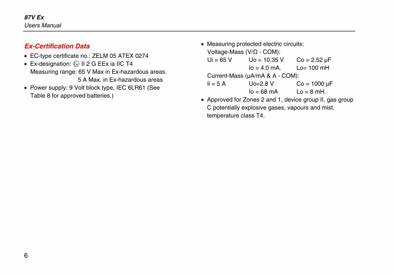
Ex-Certification Data • EC-type certificate no.: ZELM 05 ATEX 0274 • Ex-designation: ( II 2 G EEx ia IIC T4
Measuring range: 65 V Max in Ex-hazardous areas. 5 A Max. in Ex-hazardous areas
• Power supply: 9 Volt block type, IEC 6LR61 (See Table 8 for approved batteries.)
• Measuring protected electric circuits: Voltage-Mass (V/Ω - COM): Ui = 65 V Uo = 10.35 V Co = 2.52 µF Io = 4.0 mA. Lo= 100 mH Current-Mass (µA/mA & A - COM): li = 5 A Uo=2.8 V Co = 1000 µF Io = 68 mA Lo = 8 mH.
• Approved for Zones 2 and 1, device group II, gas group C potentially explosive gases, vapours and mist, temperature class T4.
True-rms Multimeter ATEX Safety Information
7
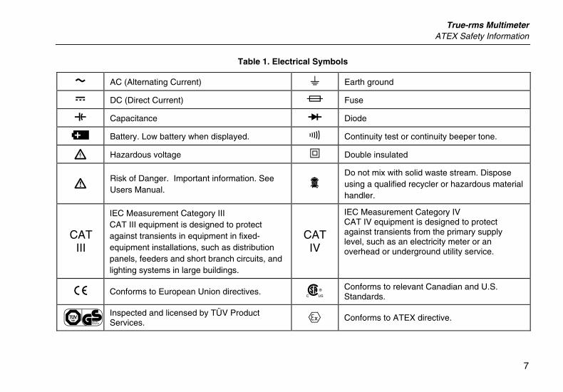
Table 1. Electrical Symbols
B AC (Alternating Current) J Earth ground
F DC (Direct Current) I Fuse
E Capacitance G Diode
M Battery. Low battery when displayed. R Continuity test or continuity beeper tone.
X Hazardous voltage T Double insulated
W Risk of Danger. Important information. See Users Manual. =
Do not mix with solid waste stream. Dispose using a qualified recycler or hazardous material handler.
CAT III
IEC Measurement Category III CAT III equipment is designed to protect against transients in equipment in fixed-equipment installations, such as distribution panels, feeders and short branch circuits, and lighting systems in large buildings.
CAT IV
IEC Measurement Category IV CAT IV equipment is designed to protect against transients from the primary supply level, such as an electricity meter or an overhead or underground utility service.
P Conforms to European Union directives. ) Conforms to relevant Canadian and U.S. Standards.
s Inspected and licensed by TÜV Product Services. ( Conforms to ATEX directive.
87V Ex Users Manual
8
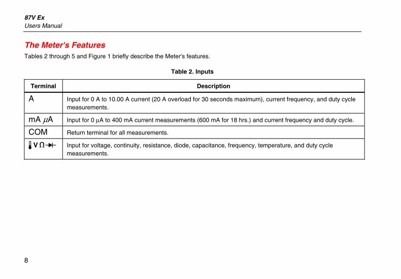
The Meter's Features Tables 2 through 5 and Figure 1 briefly describe the Meter's features.
Table 2. Inputs
Terminal Description
A Input for 0 A to 10.00 A current (20 A overload for 30 seconds maximum), current frequency, and duty cycle measurements.
mA µA Input for 0 µA to 400 mA current measurements (600 mA for 18 hrs.) and current frequency and duty cycle.
COM Return terminal for all measurements.
I Input for voltage, continuity, resistance, diode, capacitance, frequency, temperature, and duty cycle measurements.
True-rms Multimeter The Meter's Features
9
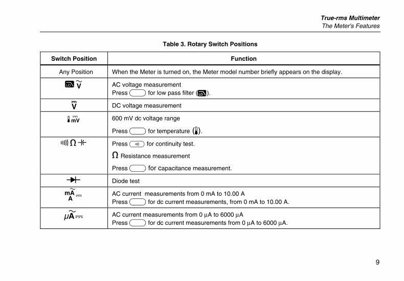
Table 3. Rotary Switch Positions
Switch Position Function
Any Position When the Meter is turned on, the Meter model number briefly appears on the display.
J AC voltage measurement Press A for low pass filter (K).
L DC voltage measurement
600 mV dc voltage range M
Press A for temperature (T).
N Press E for continuity test.
e Resistance measurement
Press A for capacitance measurement.
O Diode test
P AC current measurements from 0 mA to 10.00 A Press A for dc current measurements, from 0 mA to 10.00 A.
Q AC current measurements from 0 µA to 6000 µA Press A for dc current measurements from 0 µA to 6000 µA.
87V Ex Users Manual
10
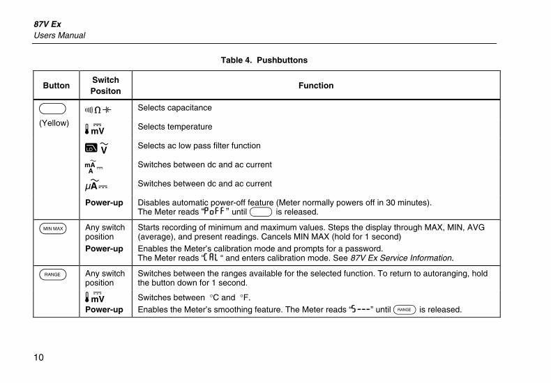
Table 4. Pushbuttons
Button Switch Positon
Function
N Selects capacitance
M Selects temperature
J Selects ac low pass filter function
P Switches between dc and ac current
Q Switches between dc and ac current
A (Yellow)
Power-up Disables automatic power-off feature (Meter normally powers off in 30 minutes). The Meter reads “PoFF” until A is released.
B Any switch position Power-up
Starts recording of minimum and maximum values. Steps the display through MAX, MIN, AVG (average), and present readings. Cancels MIN MAX (hold for 1 second) Enables the Meter’s calibration mode and prompts for a password. The Meter reads “CAL“ and enters calibration mode. See 87V Ex Service Information.
C Any switch position
Switches between the ranges available for the selected function. To return to autoranging, hold the button down for 1 second.
M Power-up
Switches between °C and °F.
Enables the Meter’s smoothing feature. The Meter reads “5___” until C is released.
True-rms Multimeter The Meter's Features
11
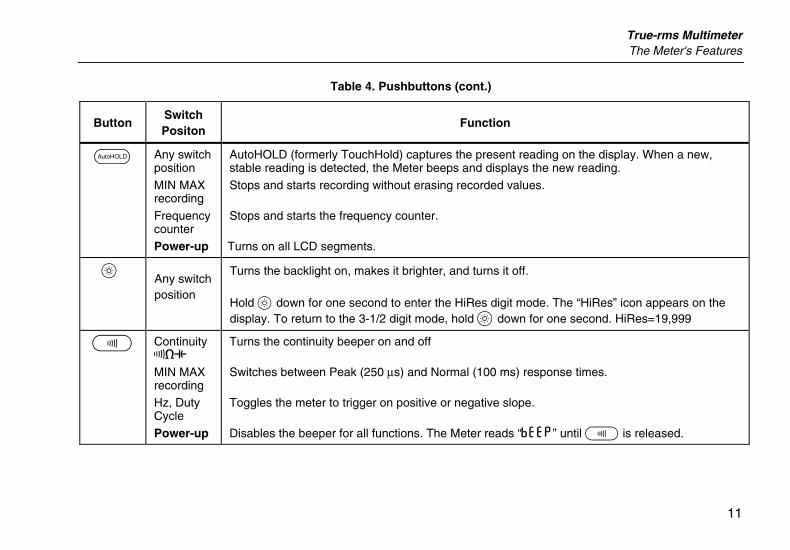
Table 4. Pushbuttons (cont.)
Button Switch Positon
Function
D Any switch position
MIN MAX recording
Frequency counter Power-up
AutoHOLD (formerly TouchHold) captures the present reading on the display. When a new, stable reading is detected, the Meter beeps and displays the new reading.
Stops and starts recording without erasing recorded values. Stops and starts the frequency counter.
Turns on all LCD segments.
H Any switch position
Turns the backlight on, makes it brighter, and turns it off. Hold H down for one second to enter the HiRes digit mode. The “HiRes” icon appears on the display. To return to the 3-1/2 digit mode, hold H down for one second. HiRes=19,999
E Continuity ReE
MIN MAX recording Hz, Duty Cycle
Power-up
Turns the continuity beeper on and off Switches between Peak (250 µs) and Normal (100 ms) response times.
Toggles the meter to trigger on positive or negative slope.
Disables the beeper for all functions. The Meter reads “bEEP” until E is released.
87V Ex Users Manual
12
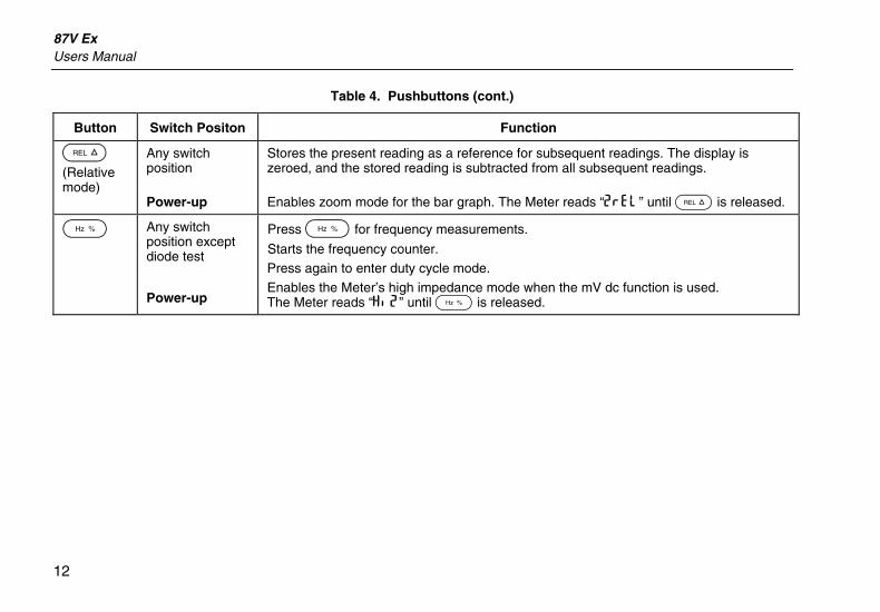
Table 4. Pushbuttons (cont.)
Button Switch Positon Function
F
(Relative mode)
Any switch position Power-up
Stores the present reading as a reference for subsequent readings. The display is zeroed, and the stored reading is subtracted from all subsequent readings.
Enables zoom mode for the bar graph. The Meter reads “2rEL” until F is released.
G
Any switch position except diode test
Power-up
Press G for frequency measurements. Starts the frequency counter. Press again to enter duty cycle mode.
Enables the Meter’s high impedance mode when the mV dc function is used. The Meter reads “Hi2” until G is released.
True-rms Multimeter The Meter's Features
13
aom1_af.eps
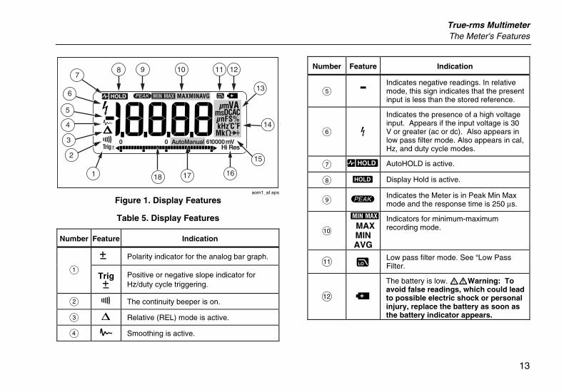
Figure 1. Display Features
Table 5. Display Features
Number Feature Indication
Y Polarity indicator for the analog bar graph.
A TrigY
Positive or negative slope indicator for Hz/duty cycle triggering.
B X The continuity beeper is on.
C W Relative (REL) mode is active.
D g Smoothing is active.
Number Feature Indication
E - Indicates negative readings. In relative mode, this sign indicates that the present input is less than the stored reference.
F Z Indicates the presence of a high voltage input. Appears if the input voltage is 30 V or greater (ac or dc). Also appears in low pass filter mode. Also appears in cal, Hz, and duty cycle modes.
G RS AutoHOLD is active.
H S Display Hold is active.
I p Indicates the Meter is in Peak Min Max mode and the response time is 250 µs.
J
m MAX MIN AVG
Indicators for minimum-maximum recording mode.
K K Low pass filter mode. See “Low Pass Filter.
L b
The battery is low. XWWarning: To avoid false readings, which could lead to possible electric shock or personal injury, replace the battery as soon as the battery indicator appears.
87V Ex Users Manual
14
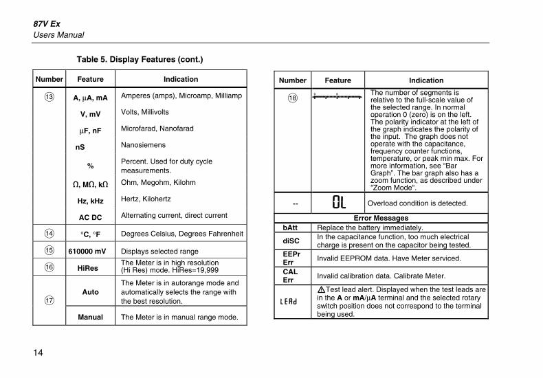
Table 5. Display Features (cont.)
Number Feature Indication
M A, µA, mA Amperes (amps), Microamp, Milliamp
V, mV Volts, Millivolts
µF, nF Microfarad, Nanofarad
nS Nanosiemens
% Percent. Used for duty cycle measurements.
e, Me, ke Ohm, Megohm, Kilohm
Hz, kHz Hertz, Kilohertz
AC DC Alternating current, direct current
N °C, °F Degrees Celsius, Degrees Fahrenheit
O 610000 mV Displays selected range
P HiRes The Meter is in high resolution (Hi Res) mode. HiRes=19,999
Auto The Meter is in autorange mode and automatically selects the range with the best resolution. Q
Manual The Meter is in manual range mode.
Number Feature Indication
R The number of segments is relative to the full-scale value of the selected range. In normal operation 0 (zero) is on the left. The polarity indicator at the left of the graph indicates the polarity of the input. The graph does not operate with the capacitance, frequency counter functions, temperature, or peak min max. For more information, see “Bar Graph”. The bar graph also has a zoom function, as described under "Zoom Mode".
-- 0L Overload condition is detected.
Error Messages bAtt Replace the battery immediately.
diSC In the capacitance function, too much electrical charge is present on the capacitor being tested.
EEPr Err Invalid EEPROM data. Have Meter serviced.
CAL Err Invalid calibration data. Calibrate Meter.
LEAd
WTest lead alert. Displayed when the test leads are in the A or mA/µA terminal and the selected rotary switch position does not correspond to the terminal being used.
True-rms Multimeter Making Measurements
15
Power-Up Options
Holding a button down while turning the Meter on activates a power-up option. Table 4 includes the power-up options.
Automatic Power-Off
The Meter automatically turns off if you do not turn the rotary switch or press a button for 30 minutes. If MIN MAX Recording is enabled, the Meter will not power off. To disable automatic power-off, refer to Table 4.
Input Alert Feature
If a test lead is plugged into the mA/µA or A terminal, but the rotary switch is not set to the correct current position, the beeper warns you by making a chirping sound and the display flashes “LEAd”. This warning is intended to stop you from attempting to measure voltage, continuity, resistance, capacitance, or diode values when the leads are plugged into a current terminal.
W Caution
Placing the probes across (in parallel with) a powered circuit when a lead is plugged into a current terminal can damage the circuit you are testing and blow the Meter's fuse. This can happen because the resistance through the Meter's current terminals is very low, so the Meter acts like a short circuit.
Making Measurements The following sections describe how to take measurements with the Meter.
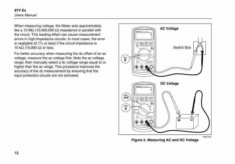
Measuring AC and DC Voltage
XW Warning To avoid possible electric shock or personal injury, never measure voltages greater than 65 volts in an Ex-hazardous area.
The Meter features true rms readings, which are accurate for distorted sine waves and other waveforms (with no dc offset) such as square waves, triangle waves, and staircase waves.
The Meter's voltage ranges are 600.0 mV, 6.000 V, 60.00 V, 600.0 V, and 1000 V. To select the 600.0 mV dc range, turn the rotary switch to mV.
To measure ac or dc voltage, refer to Figure 2.
87V Ex Users Manual
16
When measuring voltage, the Meter acts approximately like a 10 MΩ (10,000,000 Ω) impedance in parallel with the circuit. This loading effect can cause measurement errors in high-impedance circuits. In most cases, the error is negligible (0.1% or less) if the circuit impedance is 10 kΩ (10,000 Ω) or less.
For better accuracy when measuring the dc offset of an ac voltage, measure the ac voltage first. Note the ac voltage range, then manually select a dc voltage range equal to or higher than the ac range. This procedure improves the accuracy of the dc measurement by ensuring that the input protection circuits are not activated.
PEAK MIN MAX
Hi Res1 Second
OFF
mA A
mV
V
V A
A mA COM VA
400mAFUSED10A MAX
FUSED
Ex-Area:Ui = 65 VIi = 5 ATa = -20 C ... +50 C
ZELM 05 ATEX 0274Geräterückseite beachten!
Observe reverse side of unit!
1000 VCAT
CAT 600V
MIN MAX RANGE
REL Hz %
AutoHOLD
˚C/˚F
PEAK MIN MAX
Hi Res1 Second
OFF
mA A
mV
V
V A
A mA COM VA
400mAFUSED10A MAX
FUSED
Ex-Area:Ui = 65 VIi = 5 ATa = -20 C ... +50 C
ZELM 05 ATEX 0274Geräterückseite beachten!
Observe reverse side of unit!
1000 VCAT
CAT 600V
MIN MAX RANGE
REL Hz %
AutoHOLD
˚C/˚F
Switch Box
V
+
AC Voltage
DC Voltage
V
mV
ecg2f.eps
Figure 2. Measuring AC and DC Voltage
True-rms Multimeter Making Measurements
17
Zero Input Behavior of True-rms Meters
True-rms meters accurately measure distorted waveforms, but when the input leads are shorted together in the AC functions, the meter displays a residual reading between 1 and 30 counts. When the test leads are open, the display readings may fluctuate due to interference. These offset readings are normal. They do not affect the Meter’s AC measurement accuracy over the specified measurement ranges.
Unspecified input levels are:
• AC voltage: below 3 % of 600 mV AC, or 18 mV AC
• AC current: below 3 % of 60 mA AC, or 1.8 mA AC • AC current: below 3 % of 600 µA AC, or 18 µA AC
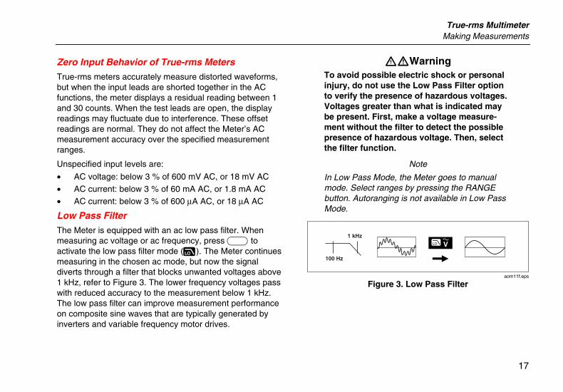
Low Pass Filter
The Meter is equipped with an ac low pass filter. When measuring ac voltage or ac frequency, press A to activate the low pass filter mode (K). The Meter continues measuring in the chosen ac mode, but now the signal diverts through a filter that blocks unwanted voltages above 1 kHz, refer to Figure 3. The lower frequency voltages pass with reduced accuracy to the measurement below 1 kHz. The low pass filter can improve measurement performance on composite sine waves that are typically generated by inverters and variable frequency motor drives.
XWWarning To avoid possible electric shock or personal injury, do not use the Low Pass Filter option to verify the presence of hazardous voltages. Voltages greater than what is indicated may be present. First, make a voltage measure-ment without the filter to detect the possible presence of hazardous voltage. Then, select the filter function.
Note
In Low Pass Mode, the Meter goes to manual mode. Select ranges by pressing the RANGE button. Autoranging is not available in Low Pass Mode.
1 kHz
100 Hz
aom11f.eps
Figure 3. Low Pass Filter
87V Ex Users Manual
18
Measuring Temperature
The Meter measures the temperature of a type-K thermocouple (included). Choose between degrees Celsius (°C) or degrees Fahrenheit (°F) by pushing C.
W Caution
To avoid possible damage to the Meter or other equipment, remember that while the Meter is rated for –200.0 °C to +1090.0 °C and –328.0 °F to 1994.0 °F, the included K-Type Thermocouple is rated to 260 °C.
Display ranges are –200.0 °C to +1090.0 °C and –328.0 °F to 1994.0 °F. Readings outside of these ranges show OL on the Meter display. When there is no thermocouple connected, the display also reads OL.
To measure temperature, do the following:
1. Connect a type-K thermocouple to the Meter’s COM and dV eG terminals.
2. Turn the rotary switch to M.
3. Press A to enter temperature mode.
4. Push C to choose Celsius or Fahrenheit.
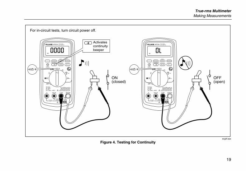
Testing for Continuity
WCaution
To avoid possible damage to the Meter or to the equipment under test, disconnect circuit power and discharge all high-voltage capacitors before testing for continuity.
The continuity test features a beeper that sounds as long as a circuit is complete. The beeper allows you to perform quick continuity tests without having to watch the display.
To test for continuity, set up the Meter as shown in Figure 4.
Press Eto turn the continuity beeper on or off.
The continuity function detects intermittent opens and shorts lasting as little as 1ms. A brief short causes the Meter to emit a short beep.
True-rms Multimeter Making Measurements
19
PEAK MIN MAX
Hi Res1 Second
OFF
mA A
mV
V
V A
A mA COM VA
400mAFUSED10A MAX
FUSED
Ex-Area:Ui = 65 VIi = 5 ATa = -20 C ... +50 C
ZELM 05 ATEX 0274Geräterückseite beachten!
Observe reverse side of unit!
1000 VCAT
CAT 600V
MIN MAX RANGE
REL Hz %
AutoHOLD
˚C/˚F
PEAK MIN MAX
Hi Res1 Second
OFF
mA A
mV
V
V A
A mA COM VA
400mAFUSED10A MAX
FUSED
Ex-Area:Ui = 65 VIi = 5 ATa = -20 C ... +50 C
ZELM 05 ATEX 0274Geräterückseite beachten!
Observe reverse side of unit!
1000 VCAT
CAT 600V
MIN MAX RANGE
REL Hz %
AutoHOLD
˚C/˚F
ON(closed)
For in-circuit tests, turn circuit power off.
Activates continuity beeper
OFF(open)
ecg4f.eps
Figure 4. Testing for Continuity
87V Ex Users Manual
20
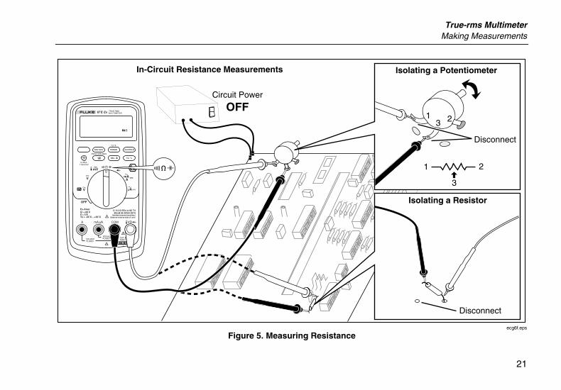
Measuring Resistance
WCaution
To avoid possible damage to the Meter or to the equipment under test, disconnect circuit power and discharge all high-voltage capacitors before measuring resistance.
The Meter measures resistance by sending a small current through the circuit. Because this current flows through all possible paths between the probes, the resistance reading represents the total resistance of all paths between the probes.
The Meter's resistance ranges are 600.0 Ω, 6.000 kΩ, 60.00 kΩ, 600.0 kΩ, 6.000 MΩ, and 50.00MΩ.
To measure resistance, set up the Meter as shown in Figure 5.
The following are some tips for measuring resistance:
• The measured value of a resistor in a circuit is often different from the resistor's rated value.
• The test leads can add 0.1 Ω to 0.2 Ω of error to resistance measurements. To test the leads, touch the probe tips together and read the resistance of the leads. If necessary, you can use the relative (REL) mode to automatically subtract this value.
• The resistance function can produce enough voltage to forward-bias silicon diode or transistor junctions, causing them to conduct. If this is suspected, press C to apply a lower current in the next higher range. If the value is higher, use the higher value.
True-rms Multimeter Making Measurements
21
PEAK MIN MAX
Hi Res1 Second
OFF
mA A
mV
V
V A
A mA COM VA
400mAFUSED10A MAX
FUSED
Ex-Area:Ui = 65 VIi = 5 ATa = -20 C ... +50 C
ZELM 05 ATEX 0274Geräterückseite beachten!
Observe reverse side of unit!
1000 VCAT
CAT 600V
MIN MAX RANGE
REL Hz %
AutoHOLD
˚C/˚F
Circuit Power
OFF
In-Circuit Resistance Measurements
Disconnect
1 2
3
Isolating a Potentiometer
13 2
Disconnect
Isolating a Resistor
ecg6f.eps
Figure 5. Measuring Resistance
87V Ex Users Manual
22
Using Conductance for High Resistance or Leakage Tests
Conductance, the inverse of resistance, is the ability of a circuit to pass current. High values of conductance correspond to low values of resistance.
The Meter's 60 nS range measures conductance in nanosiemens (1 nS = 0.000000001 Siemens). Because such small amounts of conductance correspond to extremely high resistance, the nS range lets you determine the resistance of components up to 100,000 MΩ, 1/1 nS = 1,000 MΩ.
To measure conductance, set up the Meter as shown for measuring resistance (Figure 5); then press Cuntil the nS indicator appears on the display.
The following are some tips for measuring conductance:
• High-resistance readings are susceptible to electrical noise. To smooth out most noisy readings, enter the MIN MAX recording mode; then step to the average (AVG) reading.
• There is normally a residual conductance reading with the test leads open. To ensure accurate readings, use the relative (REL) mode to subtract the residual value.
True-rms Multimeter Making Measurements
23
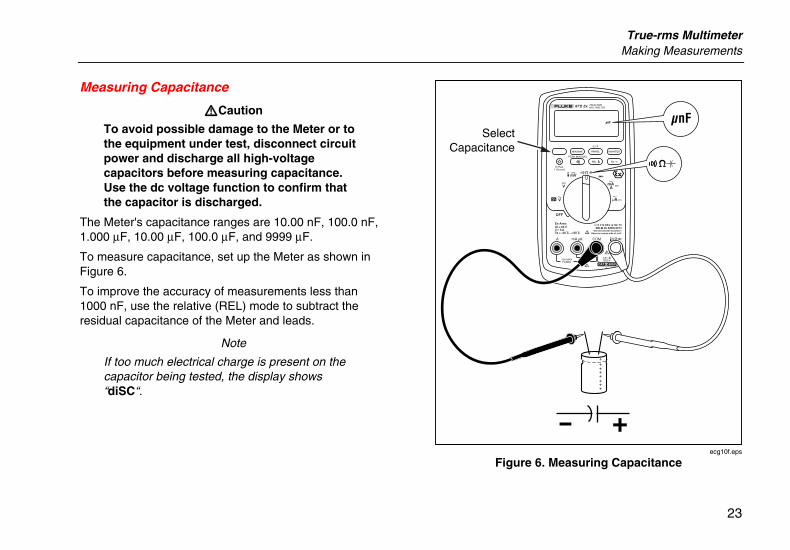
Measuring Capacitance
WCaution
To avoid possible damage to the Meter or to the equipment under test, disconnect circuit power and discharge all high-voltage capacitors before measuring capacitance. Use the dc voltage function to confirm that the capacitor is discharged.
The Meter's capacitance ranges are 10.00 nF, 100.0 nF, 1.000 µF, 10.00 µF, 100.0 µF, and 9999 µF.
To measure capacitance, set up the Meter as shown in Figure 6.
To improve the accuracy of measurements less than 1000 nF, use the relative (REL) mode to subtract the residual capacitance of the Meter and leads.
Note
If too much electrical charge is present on the capacitor being tested, the display shows “diSC“.
PEAK MIN MAX
Hi Res1 Second
OFF
mA A
mV
V
V A
A mA COM VA
400mAFUSED10A MAX
FUSED
Ex-Area:Ui = 65 VIi = 5 ATa = -20 C ... +50 C
ZELM 05 ATEX 0274Geräterückseite beachten!
Observe reverse side of unit!
1000 VCAT
CAT 600V
MIN MAX RANGE
REL Hz %
AutoHOLD
˚C/˚F
SelectCapacitance
+
++++++++
ecg10f.eps
Figure 6. Measuring Capacitance
87V Ex Users Manual
24
Testing Diodes WCaution
To avoid possible damage to the Meter or to the equipment under test, disconnect circuit power and discharge all high-voltage capacitors before testing diodes.
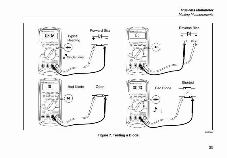
Use the diode test to check diodes, transistors, silicon controlled rectifiers (SCRs), and other semiconductor devices. This function tests a semiconductor junction by sending a current through the junction, then measuring the junction's voltage drop. A good silicon junction drops between 0.5 V and 0.8 V.
To test a diode out of a circuit, set up the Meter as shown in Figure 7. For forward-bias readings on any semiconductor component, place the red test lead on the component's positive terminal and place the black lead on the component's negative terminal.
In a circuit, a good diode should still produce a forward-bias reading of 0.5 V to 0.8 V; however, the reverse-bias reading can vary depending on the resistance of other pathways between the probe tips.
A short beep sounds if the diode is good (< .85 V). A continuous beep sounds if the reading is ≤ .100 V. This reading would indicate a short circuit. The display shows “OL” if the diode is open.
True-rms Multimeter Making Measurements
25
PEAK MIN MAX
Hi Res1 Second
OFF
mA A
mV
V
V A
A mA COM VA
400mAFUSED10A MAX
FUSED
Ex-Area:Ui = 65 VIi = 5 ATa = -20 C ... +50 C
ZELM 05 ATEX 0274Geräterückseite beachten!
Observe reverse side of unit!
1000 VCAT
CAT 600V
MIN MAX RANGE
REL Hz %
AutoHOLD
˚C/˚F
PEAK MIN MAX
Hi Res1 Second
OFF
mA A
mV
V
V A
A mA COM VA
400mAFUSED10A MAX
FUSED
Ex-Area:Ui = 65 VIi = 5 ATa = -20 C ... +50 C
ZELM 05 ATEX 0274Geräterückseite beachten!
Observe reverse side of unit!
1000 VCAT
CAT 600V
MIN MAX RANGE
REL Hz %
AutoHOLD
˚C/˚F
PEAK MIN MAX
Hi Res1 Second
OFF
mA A
mV
V
V A
A mA COM VA
400mAFUSED10A MAX
FUSED
Ex-Area:Ui = 65 VIi = 5 ATa = -20 C ... +50 C
ZELM 05 ATEX 0274Geräterückseite beachten!
Observe reverse side of unit!
1000 VCAT
CAT 600V
MIN MAX RANGE
REL Hz %
AutoHOLD
˚C/˚F
PEAK MIN MAX
Hi Res1 Second
OFF
mA A
mV
V
V A
A mA COM VA
400mAFUSED10A MAX
FUSED
Ex-Area:Ui = 65 VIi = 5 ATa = -20 C ... +50 C
ZELM 05 ATEX 0274Geräterückseite beachten!
Observe reverse side of unit!
1000 VCAT
CAT 600V
MIN MAX RANGE
REL Hz %
AutoHOLD
˚C/˚F
+Typical Reading
+Forward Bias
Reverse Bias
Bad Diode Open Bad Diode
Shorted
or
Single Beep
ecg9f.eps
Figure 7. Testing a Diode
87V Ex Users Manual
26
Measuring AC or DC Current
XWWarning To avoid possible electric shock or personal injury:
• Never attempt an in-circuit current measurement where the open-circuit potential to earth is greater than 1000 V. You may damage the Meter or be injured if the fuse blows during such a measurement.
• Never measure currents greater than 5 amps while using the Meter in an Ex-hazardous area.
WCaution
To avoid possible damage to the Meter or to the equipment under test:
• Check the Meter's fuses before measuring current.
• Use the proper terminals, function, and range for all measurements.
• Never place the probes across (in parallel with) any circuit or component when the leads are plugged into the current terminals.
To measure current, you must break the circuit under test, then place the Meter in series with the circuit.
The Meter's current ranges are 600.0 µA, 6000 µA, 60.00 mA, 400.0 mA, 6000 mA, and 10 A. AC current is displayed as an rms value.
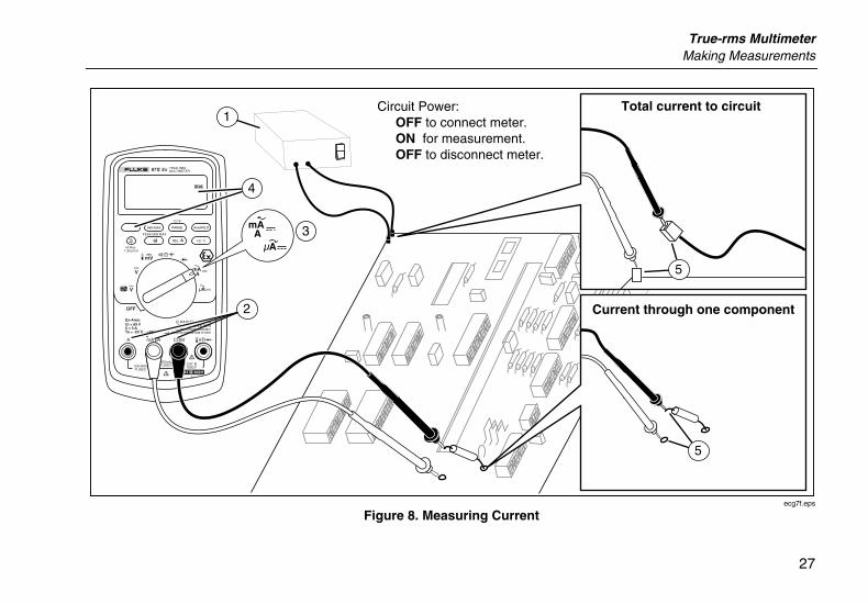
To measure current, refer to Figure 8 and proceed as follows:
1. Turn off power to the circuit. Discharge all high-voltage capacitors.
2. Insert the black lead into the COM terminal. For currents between 6 mA and 400 mA, insert the red lead into the mA/µA terminal. For currents above 400 mA, insert the red lead into the A terminal.
Note
To avoid blowing the Meter's 400 mA fuse, use the mA/µA terminal only if you are sure the current is less than 400 mA continuously or less than 600 mA for 18 hours or less.
True-rms Multimeter Making Measurements
27
PEAK MIN MAX
Hi Res1 Second
OFF
mA A
mV
V
V A
A mA COM VA
400mAFUSED10A MAX
FUSED
Ex-Area:Ui = 65 VIi = 5 ATa = -20 C ... +50 C
ZELM 05 ATEX 0274Geräterückseite beachten!
Observe reverse side of unit!
1000 VCAT
CAT 600V
MIN MAX RANGE
REL Hz %
AutoHOLD
˚C/˚F
Circuit Power: OFF to connect meter. ON for measurement. OFF to disconnect meter.
Current through one component
Total current to circuit
4
5
5
2
3
1
mA A
A
ecg7f.eps
Figure 8. Measuring Current
87V Ex Users Manual
28
3. If you are using the A terminal, set the rotary switch to mA/A. If you are using the mA/µA terminal, set the rotary switch to µA for currents below 6000 µA (6 mA), or mA/A for currents above 6000 µA.
4. To measure dc current, press A.
5. Break the circuit path to be tested. Touch the black probe to the more negative side of the break; touch the red probe to the more positive side of the break. Reversing the leads will produce a negative reading, but will not damage the Meter.
6. Turn on power to the circuit; then read the display. Be sure to note the unit given at the right side of the display (µA, mA, or A).
7. Turn off power to the circuit and discharge all high-voltage capacitors. Remove the Meter and restore the circuit to normal operation.
The following are some tips for measuring current:
• If the current reading is 0 and you are sure the Meter is set up correctly, test the Meter's fuses as described under "Testing the Fuses".
• A current Meter drops a small voltage across itself, which might affect circuit operation. You can calculate this burden voltage using the values listed in the Current Function specifications table.
True-rms Multimeter Making Measurements
29
Measuring Frequency
The Meter measures the frequency of a voltage or current signal by counting the number of times the signal crosses a threshold level each second.
Table 6 summarizes the trigger levels and applications for measuring frequency using the various ranges of the Meter's voltage and current functions.
To measure frequency, connect the Meter to the signal source; then press G. Pressing Eswitches the trigger slope between + and -, as indicated by the symbol at the left side of the display (refer to Figure 9 under "Measuring Duty Cycle"). Pressing Dstops and starts the counter.
The Meter autoranges to one of five frequency ranges: 199.99 Hz, 1999.9 Hz, 19.999 kHz, 199.99 kHz, and greater than 200 kHz. For frequencies below 10 Hz, the display is updated at the frequency of the input. Below 0.5 Hz, the display may be unstable.
The following are some tips for measuring frequency:
• If a reading shows as 0 Hz or is unstable, the input signal may be below or near the trigger level. You can usually correct these problems by selecting a lower range, which increases the sensitivity of the Meter. In the L function, the lower ranges also have lower trigger levels.
• If a reading seems to be a multiple of what you expect, the input signal may be distorted. Distortion can cause multiple triggerings of the frequency counter. Selecting a higher voltage range might solve this problem by decreasing the sensitivity of the Meter. You can also try selecting a dc range, which raises the trigger level. In general, the lowest frequency displayed is the correct one.
87V Ex Users Manual
30
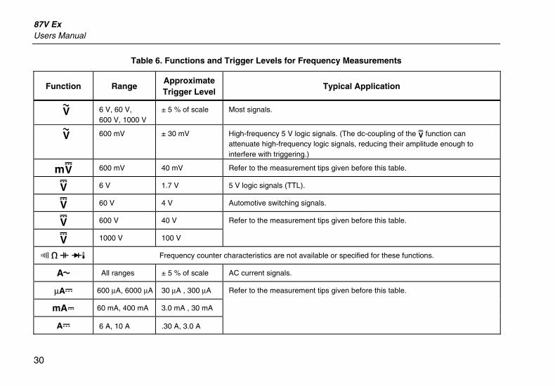
Table 6. Functions and Trigger Levels for Frequency Measurements
Function Range Approximate Trigger Level
Typical Application
K 6 V, 60 V, 600 V, 1000 V
± 5 % of scale Most signals.
K 600 mV ± 30 mV High-frequency 5 V logic signals. (The dc-coupling of the L function can attenuate high-frequency logic signals, reducing their amplitude enough to interfere with triggering.)
mL 600 mV 40 mV Refer to the measurement tips given before this table.
L 6 V 1.7 V 5 V logic signals (TTL).
L 60 V 4 V Automotive switching signals.
L 600 V 40 V Refer to the measurement tips given before this table.
L 1000 V 100 V
R e E Gd Frequency counter characteristics are not available or specified for these functions.
\ All ranges ± 5 % of scale AC current signals.
µAF 600 µA, 6000 µA 30 µA , 300 µA Refer to the measurement tips given before this table.
^ 60 mA, 400 mA 3.0 mA , 30 mA
AF 6 A, 10 A .30 A, 3.0 A
True-rms Multimeter Making Measurements
31
Measuring Duty Cycle
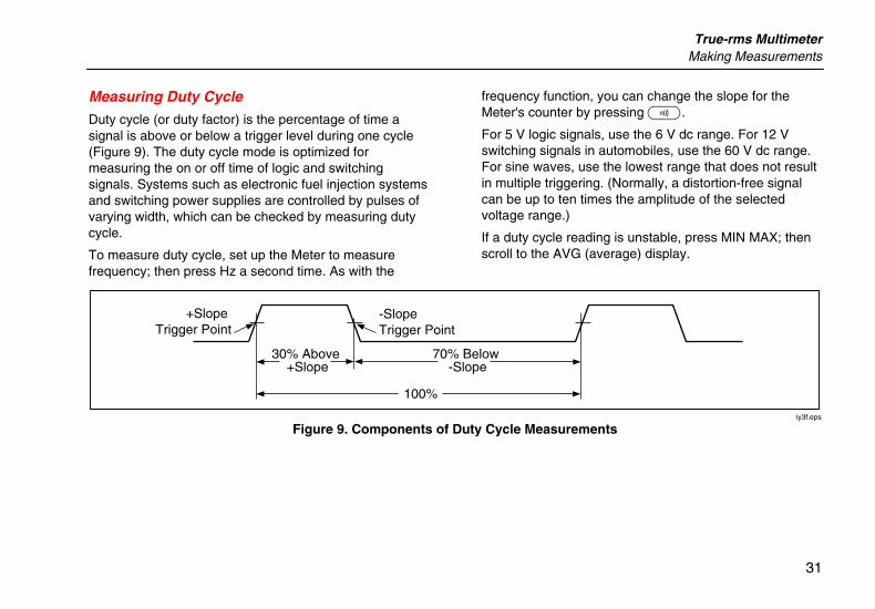
Duty cycle (or duty factor) is the percentage of time a signal is above or below a trigger level during one cycle (Figure 9). The duty cycle mode is optimized for measuring the on or off time of logic and switching signals. Systems such as electronic fuel injection systems and switching power supplies are controlled by pulses of varying width, which can be checked by measuring duty cycle.
To measure duty cycle, set up the Meter to measure frequency; then press Hz a second time. As with the
frequency function, you can change the slope for the Meter's counter by pressing E.
For 5 V logic signals, use the 6 V dc range. For 12 V switching signals in automobiles, use the 60 V dc range. For sine waves, use the lowest range that does not result in multiple triggering. (Normally, a distortion-free signal can be up to ten times the amplitude of the selected voltage range.)
If a duty cycle reading is unstable, press MIN MAX; then scroll to the AVG (average) display.
-Slope Trigger Point
+Slope Trigger Point
30% Above +Slope
70% Below -Slope
100%
iy3f.eps
Figure 9. Components of Duty Cycle Measurements
87V Ex Users Manual
32
Determining Pulse Width
For a periodic waveform (its pattern repeats at equal time intervals), you can determine the amount of time that the signal is high or low as follows:
1. Measure the signal's frequency.
2. Press Ga second time to measure the signal's duty cycle. Press E to select a measurement of the signal's positive or negative pulse, refer to Figure 9.
3. Use the following formula to determine the pulse width:
Pulse Width = % Duty Cycle ÷ 100 (in seconds) Frequency
Bar Graph The analog bar graph functions like the needle on an analog meter, but without the overshoot. The bar graph updates 40 times per second. Because the graph responds 10 times faster than the digital display, it is useful for making peak and null adjustments and observing rapidly changing inputs. The graph is not shown for capacitance, frequency counter functions, temperature, or peak min max.
The number of lit segments indicates the measured value and is relative to the full-scale value of the selected range.
In the 60 V range, for example, the major divisions on the scale represent 0, 15, 30, 45, and 60 V. An input of -30 V lights the negative sign and the segments up to the middle of the scale.
The bar graph also has a zoom function, as described under "Zoom Mode".
True-rms Multimeter HiRes Mode
33
Zoom Mode (Power Up Option Only)
To use the Rel Zoom Bar Graph:
1. Hold down F while turning the Meter on. The display reads “2rEL”.
2. Select the relative mode by pressing F again.
3. The center of the bar graph now represents zero and the sensitivity of the bar graph increases by a factor of 10. Measured values more negative than the stored reference activate segments to the left of center; values more positive activate segments to the right of center.
Uses for the Zoom Mode
The relative mode, combined with the increased sensitivity of the bar graph's zoom mode, helps you make fast and accurate zero and peak adjustments.
For zero adjustments, set the Meter to the desired function, short the test leads together, press F; then connect the leads to the circuit under test. Adjust the circuit's variable component until the display reads zero. Only the center segment on the zoom bar graph is lit.
For peak adjustments, set the Meter to the desired function, connect the leads to the circuit under test; then press F. The display reads zero. As you adjust for a positive or negative peak, the bar graph length increases
to the right or left of zero. If an overange symbol lights (< >), press F twice to set a new reference; then continue with the adjustment.
HiRes Mode Pressing H for one second causes the Meter to enter the high-resolution (HiRes), 4-1/2 digit mode. Readings are displayed at 10 times the normal resolution with a maximum display of 19,999 counts. The HiRes mode works in all modes except capacitance, frequency counter functions, temperature, and the 250 µs (peak) MIN MAX modes.
To return to the 3-1/2 digit mode, press H again for one second.
87V Ex Users Manual
34
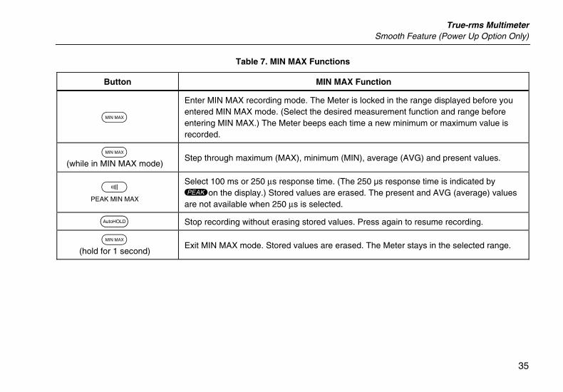
MIN MAX Recording Mode The MIN MAX mode records minimum and maximum input values. When the inputs go below the recorded minimum value or above the recorded maximum value, the Meter beeps and records the new value. This mode can be used to capture intermittent readings, record maximum readings while you are away or record readings while you are operating the equipment under test and cannot watch the Meter. MIN MAX mode can also calculate an average of all readings taken since the MIN MAX mode was activated. To use MIN MAX mode, refer to the functions in Table 7.
Response time is the length of time an input must stay at a new value to be recorded. A shorter response time captures shorter events, but with decreased accuracy. Changing the response time erases all recorded readings. The Meter has 100 millisecond, and 250 µs (peak) response times. The 250 µs response time is indicated by "p" on the display.
The 100 millisecond response time is best for recording power supply surges, inrush currents, and finding intermittent failures.
The true average value (AVG) displayed in the 100 ms mode is the mathematical integral of all readings taken since the start of recording (overloads are discarded). The average reading is useful for smoothing out unstable
inputs, calculating power consumption, or estimating the percentage of time a circuit is active.
Min Max records the signal extremes lasting longer than 100 ms.
Peak records the signal extremes lasting longer than 250 µs.
Smooth Feature (Power Up Option Only) When the input signal changes rapidly, “smoothing” provides a steadier reading on the display.
To use the smooth feature:
1. Hold down C while turning the Meter on. The display will read “5___” until C is released.
2. The smooth icon (g) will appear on the left side of the display to let you know that smoothing is active.
True-rms Multimeter Smooth Feature (Power Up Option Only)
35
Table 7. MIN MAX Functions
Button MIN MAX Function
B
Enter MIN MAX recording mode. The Meter is locked in the range displayed before you entered MIN MAX mode. (Select the desired measurement function and range before entering MIN MAX.) The Meter beeps each time a new minimum or maximum value is recorded.
B (while in MIN MAX mode) Step through maximum (MAX), minimum (MIN), average (AVG) and present values.
E PEAK MIN MAX
Select 100 ms or 250 µs response time. (The 250 µs response time is indicated by pon the display.) Stored values are erased. The present and AVG (average) values are not available when 250 µs is selected.
D Stop recording without erasing stored values. Press again to resume recording.
B (hold for 1 second)
Exit MIN MAX mode. Stored values are erased. The Meter stays in the selected range.
87V Ex Users Manual
36
AutoHOLD Mode XWWarning
To avoid possible electric shock or personal injury, do not use AutoHOLD mode to determine that circuits are without power. The AutoHOLD mode will not capture unstable or noisy readings.
The AutoHOLD mode captures the present reading on the display. When a new, stable reading is detected, the Meter beeps and displays the new reading. To enter or exit AutoHOLD mode, press D.
Relative Mode Selecting relative mode ( F) causes the Meter to zero the display and store the present reading as the reference for subsequent measurements. The Meter is locked into the range selected when you pressed F. Press Fagain to exit this mode.
In relative mode, the reading shown is always the difference between the present reading and the stored reference value. For example, if the stored reference value is 15.00 V and the present reading is 14.10 V, the display shows -0.90 V.
True-rms Multimeter Maintenance
37
Maintenance XWWarning
To avoid possible electric shock or personal injury, servicing not covered in this manual should be performed only by the manufacturer. Repair or service by others may void the ATEX certification of this Meter.
General Maintenance
Periodically wipe the case with a damp cloth. Do not use abrasives or solvents.
Caution
To avoid weakening the case and possibly developing cracks, do not use Acetone to clean the Meter
Dirt or moisture in the terminals can affect readings and can falsely activate the Input Alert feature. Clean the terminals as follows:
1. Turn the Meter off and remove all test leads.
2. Shake out any dirt that may be in the terminals.
3. Soak a new swab with a cleaning and oiling agent (such as WD-40). Work the swab around in each terminal. The oiling agent insulates the terminals from moisture-related activation of the Input Alert feature.
Fuse Test
If a test lead is plugged into the mA/µA or A terminal and the rotary switch is turned to a non-current function, the Meter chirps and flashes “LEAd” if the fuse associated with that current terminal is good. If the Meter does not chirp or flash “LEAd”, the fuse is bad and must be replaced. Refer to Table 9 for the appropriate replacement fuse.
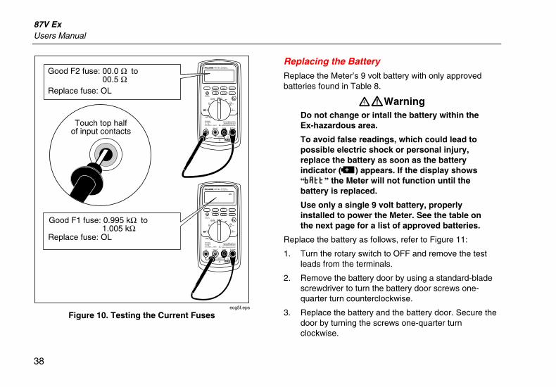
To test the quality of the fuse: before measuring current, test the appropriate fuse as shown in Figure 10. If the tests give readings other than those shown, have the Meter serviced.
XWWarning To avoid electrical shock or personal injury, remove the test leads and any input signals before replacing the battery or fuses. To prevent damage or injury, install ONLY approved fuses shown in Table 9.
87V Ex Users Manual
38
PEAK MIN MAX
Hi Res1 Second
OFF
mA A
mV
V
V A
A mA COM VA
400mAFUSED10A MAX
FUSED
Ex-Area:Ui = 65 VIi = 5 ATa = -20 C ... +50 C
ZELM 05 ATEX 0274Geräterückseite beachten!
Observe reverse side of unit!
1000 VCAT
CAT 600V
MIN MAX RANGE
REL Hz %
AutoHOLD
˚C/˚F
PEAK MIN MAX
Hi Res1 Second
OFF
mA A
mV
V
V A
A mA COM VA
400mAFUSED10A MAX
FUSED
Ex-Area:Ui = 65 VIi = 5 ATa = -20 C ... +50 C
ZELM 05 ATEX 0274Geräterückseite beachten!
Observe reverse side of unit!
1000 VCAT
CAT 600V
MIN MAX RANGE
REL Hz %
AutoHOLD
˚C/˚F
Good F2 fuse: 00.0 Ω to 00.5 Ω
Good F1 fuse: 0.995 kΩ to 1.005 kΩ
Replace fuse: OL
Replace fuse: OL
Touch top halfof input contacts
ecg5f.eps
Figure 10. Testing the Current Fuses
Replacing the Battery
Replace the Meter’s 9 volt battery with only approved batteries found in Table 8.
XWWarning Do not change or intall the battery within the Ex-hazardous area.
To avoid false readings, which could lead to possible electric shock or personal injury, replace the battery as soon as the battery indicator (b) appears. If the display shows “bAtt” the Meter will not function until the battery is replaced.
Use only a single 9 volt battery, properly installed to power the Meter. See the table on the next page for a list of approved batteries.
Replace the battery as follows, refer to Figure 11:
1. Turn the rotary switch to OFF and remove the test leads from the terminals.
2. Remove the battery door by using a standard-blade screwdriver to turn the battery door screws one-quarter turn counterclockwise.
3. Replace the battery and the battery door. Secure the door by turning the screws one-quarter turn clockwise.
True-rms Multimeter Maintenance
39
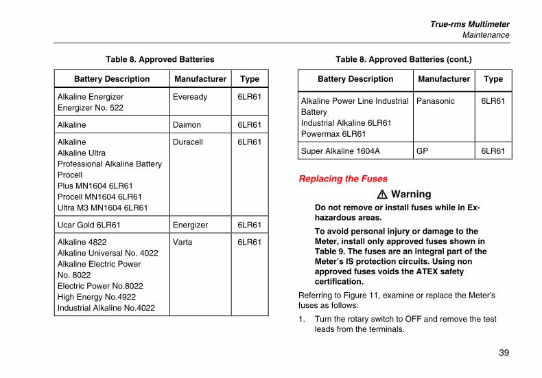
Table 8. Approved Batteries
Battery Description Manufacturer Type
Alkaline Energizer Energizer No. 522
Eveready 6LR61
Alkaline Daimon 6LR61
Alkaline Alkaline Ultra Professional Alkaline Battery Procell Plus MN1604 6LR61 Procell MN1604 6LR61 Ultra M3 MN1604 6LR61
Duracell 6LR61
Ucar Gold 6LR61 Energizer 6LR61
Alkaline 4822 Alkaline Universal No. 4022 Alkaline Electric Power No. 8022 Electric Power No.8022 High Energy No.4922 Industrial Alkaline No.4022
Varta 6LR61
Table 8. Approved Batteries (cont.)
Battery Description Manufacturer Type
Alkaline Power Line Industrial Battery Industrial Alkaline 6LR61 Powermax 6LR61
Panasonic 6LR61
Super Alkaline 1604A GP 6LR61
Replacing the Fuses
W Warning Do not remove or install fuses while in Ex-hazardous areas.
To avoid personal injury or damage to the Meter, install only approved fuses shown in Table 9. The fuses are an integral part of the Meter’s IS protection circuits. Using non approved fuses voids the ATEX safety certification.
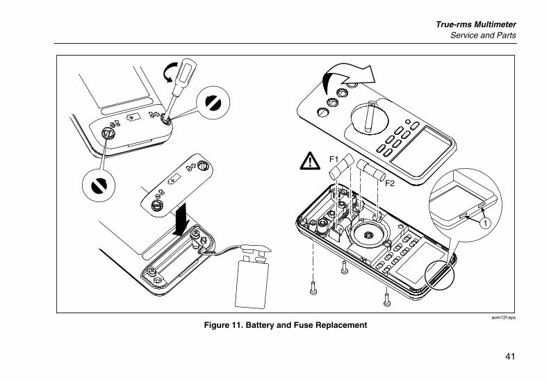
Referring to Figure 11, examine or replace the Meter's fuses as follows:
1. Turn the rotary switch to OFF and remove the test leads from the terminals.
87V Ex Users Manual
40
2. Remove the battery door by using a standard-blade screwdriver to turn the battery door screws one-quarter turn counterclockwise.
3. Remove the three Phillips-head screws from the case bottom and turn the case over.
4. Gently push up the input terminal-end of the top case from inside of the battery compartment to separate the two halves of the case.
5. Remove the fuse by gently prying one end loose, then sliding the fuse out of its bracket.
6. Install ONLY specified replacement fuses shown in Table 9.
7. Verify that the rotary switch and the circuit board switch are in the OFF position.
8. Replace the case top, ensuring that the gasket is properly seated and case snaps together above the LCD (item A).
9. Reinstall the three screws and the battery door. Secure the door by turning the screws one-quarter turn clockwise.
Service and Parts If the Meter fails, check the battery and fuses. Review this manual to verify proper use of the Meter.
Replacement parts and accessories are shown in Tables 9 and 10 and Figure 12.
To order parts and accessories, refer to “Contacting Fluke”.
True-rms Multimeter Service and Parts
41
F1
F2
1
aom12f.eps
Figure 11. Battery and Fuse Replacement
87V Ex Users Manual
42
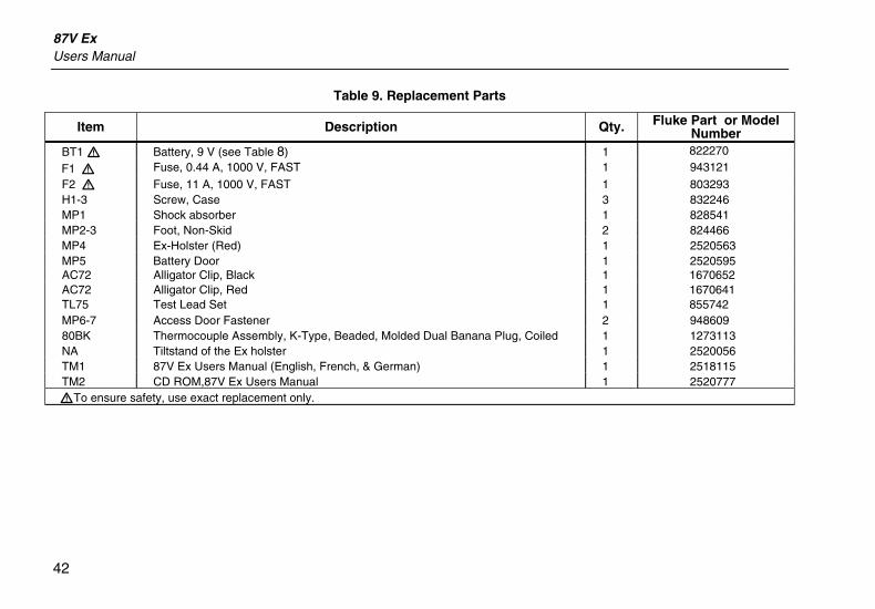
Table 9. Replacement Parts
Item Description Qty. Fluke Part or Model Number
BT1 W Battery, 9 V (see Table 8) 1 822270
F1 W Fuse, 0.44 A, 1000 V, FAST 1 943121
F2 W Fuse, 11 A, 1000 V, FAST 1 803293 H1-3 Screw, Case 3 832246 MP1 Shock absorber 1 828541 MP2-3 Foot, Non-Skid 2 824466 MP4 Ex-Holster (Red) 1 2520563 MP5 Battery Door 1 2520595 AC72 Alligator Clip, Black 1 1670652 AC72 Alligator Clip, Red 1 1670641 TL75 Test Lead Set 1 855742 MP6-7 Access Door Fastener 2 948609 80BK Thermocouple Assembly, K-Type, Beaded, Molded Dual Banana Plug, Coiled 1 1273113 NA Tiltstand of the Ex holster 1 2520056 TM1 87V Ex Users Manual (English, French, & German) 1 2518115 TM2 CD ROM,87V Ex Users Manual 1 2520777 WTo ensure safety, use exact replacement only.
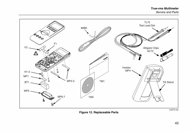
True-rms Multimeter Service and Parts
43
HolsterMP4
Alligator Clips
TM2
TL75Test Lead Set
Tilt Stand
F2
TM1
80BK
AC72
BT1
MP5
H1-3
MP2-3
MP1
F1
MP6-7
ecg015c.eps
Figure 12. Replaceable Parts
87V Ex Users Manual
44
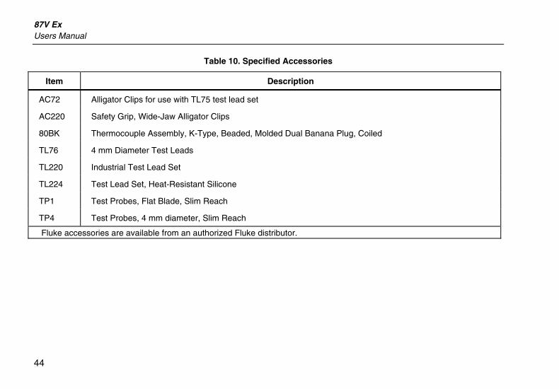
Table 10. Specified Accessories
Item Description
AC72 Alligator Clips for use with TL75 test lead set
AC220 Safety Grip, Wide-Jaw Alligator Clips
80BK Thermocouple Assembly, K-Type, Beaded, Molded Dual Banana Plug, Coiled
TL76 4 mm Diameter Test Leads
TL220 Industrial Test Lead Set
TL224 Test Lead Set, Heat-Resistant Silicone
TP1 Test Probes, Flat Blade, Slim Reach
TP4 Test Probes, 4 mm diameter, Slim Reach
Fluke accessories are available from an authorized Fluke distributor.
True-rms Multimeter General Specifications
45
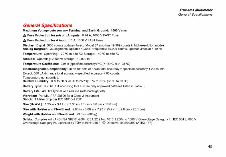
General Specifications Maximum Voltage between any Terminal and Earth Ground: 1000 V rms W Fuse Protection for mA or µA inputs: 0.44 A, 1000 V FAST Fuse W Fuse Protection for A input: 11 A, 1000 V FAST Fuse Display: Digital: 6000 counts updates 4/sec; (Model 87 also has 19,999 counts in high-resolution mode). Analog Bargraph: 33 segments, updates 40/sec. Frequency: 19,999 counts, updates 3/sec at > 10 Hz Temperature: Operating: -20 ºC to +50 ºC; Storage: -40 ºC to +60 ºC Altitude: Operating: 2000 m; Storage: 10,000 m Temperature Coefficient: 0.05 x (specified accuracy)/ ºC (< 18 ºC or > 28 ºC) Electromagnetic Compatibility: In an RF field of 3 V/m total accuracy = specified accuracy + 20 counts Except: 600 µA dc range total accuracy=specified accuracy + 60 counts. Temperature not specified. Relative Humidity: 0 % to 80 % (0 ºC to 35 ºC); 0 % to 70 % (35 ºC to 50 ºC) Battery Type: 9 V, 6LR61 according to IEC (Use only approved batteries listed in Table 8) Battery Life: 400 hrs typical with alkaline (with backlight off) Vibration: Per MIL-PRF-28800 for a Class 2 instrument Shock: 1 Meter drop per IEC 61010-1:2001 Size (HxWxL): 1.25 in x 3.41 in x 7.35 in (3.1 cm x 8.6 cm x 18.6 cm) Size with Holster and Flex-Stand: 2.06 in x 3.86 in x 7.93 in (5.2 cm x 9.8 cm x 20.1 cm) Weight with Holster and Flex-Stand: 23.3 oz (660 g) Safety: Complies with ANSI/ISA S82.01-2004, CSA 22.2 No. 1010.1:2004 to 1000 V Overvoltage Category III, IEC 664 to 600 V Overvoltage Category IV. Licensed by TÜV to EN61010-1. ( Directive 1992/92/EC (ATEX 137)
87V Ex Users Manual
46
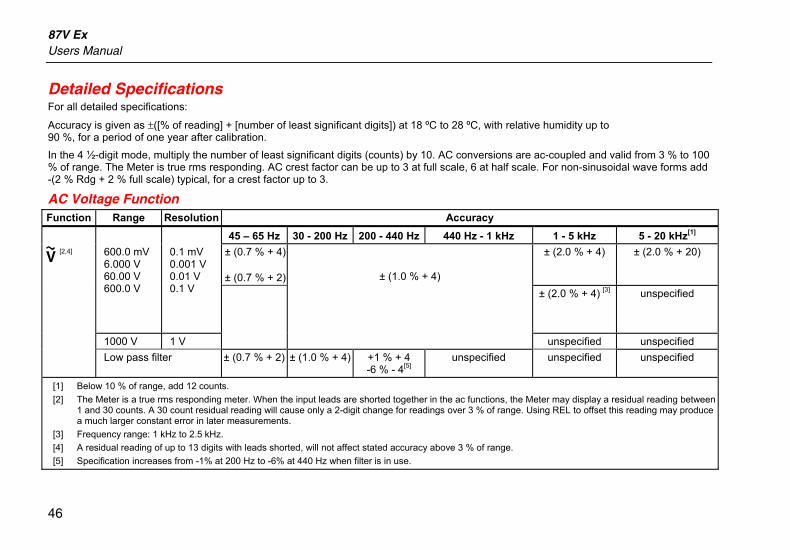
Detailed Specifications For all detailed specifications:
Accuracy is given as ±([% of reading] + [number of least significant digits]) at 18 ºC to 28 ºC, with relative humidity up to 90 %, for a period of one year after calibration. In the 4 ½-digit mode, multiply the number of least significant digits (counts) by 10. AC conversions are ac-coupled and valid from 3 % to 100 % of range. The Meter is true rms responding. AC crest factor can be up to 3 at full scale, 6 at half scale. For non-sinusoidal wave forms add -(2 % Rdg + 2 % full scale) typical, for a crest factor up to 3.
AC Voltage Function Function Range Resolution Accuracy
45 – 65 Hz 30 - 200 Hz 200 - 440 Hz 440 Hz - 1 kHz 1 - 5 kHz 5 - 20 kHz[1] ± (0.7 % + 4) ± (0.7 % + 2)
± (2.0 % + 4)
± (2.0 % + 20)
600.0 mV 6.000 V 60.00 V 600.0 V
0.1 mV 0.001 V 0.01 V 0.1 V ± (2.0 % + 4) [3] unspecified
1000 V 1 V
± (1.0 % + 4)
unspecified unspecified
K [2,4]
Low pass filter ± (0.7 % + 2) ± (1.0 % + 4) +1 % + 4 -6 % - 4[5]
unspecified unspecified unspecified
[1] Below 10 % of range, add 12 counts. [2] The Meter is a true rms responding meter. When the input leads are shorted together in the ac functions, the Meter may display a residual reading between
1 and 30 counts. A 30 count residual reading will cause only a 2-digit change for readings over 3 % of range. Using REL to offset this reading may produce a much larger constant error in later measurements.
[3] Frequency range: 1 kHz to 2.5 kHz. [4] A residual reading of up to 13 digits with leads shorted, will not affect stated accuracy above 3 % of range. [5] Specification increases from -1% at 200 Hz to -6% at 440 Hz when filter is in use.
True-rms Multimeter Detailed Specifications
47
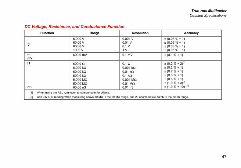
DC Voltage, Resistance, and Conductance Function
Function Range Resolution Accuracy
L
6.000 V 60.00 V 600.0 V 1000 V
0.001 V 0.01 V 0.1 V 1 V
± (0.05 % + 1) ± (0.05 % + 1) ± (0.05 % + 1) ± (0.05 % + 1)
F mV
600.0 mV 0.1 mV ± (0.1 % + 1)
e
nS
600.0 Ω 6.000 kΩ 60.00 kΩ 600.0 kΩ 6.000 MΩ 50.00 MΩ 60.00 nS
0.1 Ω 0.001 kΩ 0.01 kΩ 0.1 kΩ 0.001 MΩ 0.01 MΩ 0.01 nS
± (0.2 % + 2)[1] ± (0.2 % + 1) ± (0.2 % + 1) ± (0.6 % + 1) ± (0.6 % + 1) ± (1.0 % + 3)[2] ± (1.0 % + 10)[1,2]
[1] When using the REL ∆ function to compensate for offsets. [2] Add 0.5 % of reading when measuring above 30 MΩ in the 50 MΩ range, and 20 counts below 33 nS in the 60 nS range.
87V Ex Users Manual
48
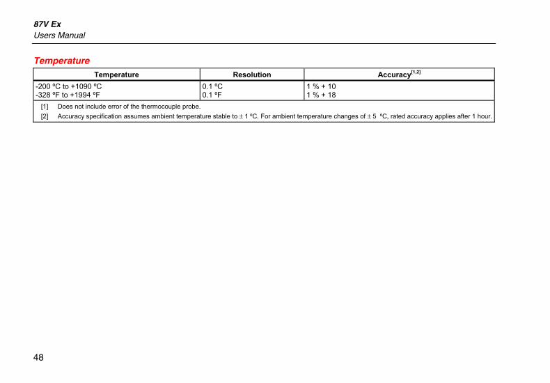
Temperature Temperature Resolution Accuracy[1,2]
-200 ºC to +1090 ºC -328 ºF to +1994 ºF
0.1 ºC 0.1 ºF
1 % + 10 1 % + 18
[1] Does not include error of the thermocouple probe. [2] Accuracy specification assumes ambient temperature stable to ± 1 ºC. For ambient temperature changes of ± 5 ºC, rated accuracy applies after 1 hour.
True-rms Multimeter Detailed Specifications
49
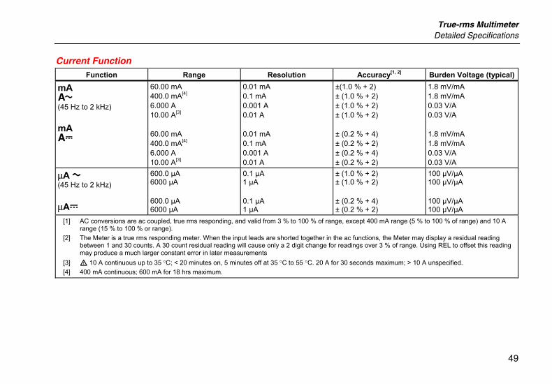
Current Function Function Range Resolution Accuracy[1, 2] Burden Voltage (typical)
mA \ (45 Hz to 2 kHz) mA [
60.00 mA 400.0 mA[4] 6.000 A 10.00 A[3] 60.00 mA 400.0 mA[4] 6.000 A 10.00 A[3]
0.01 mA 0.1 mA 0.001 A 0.01 A 0.01 mA 0.1 mA 0.001 A 0.01 A
±(1.0 % + 2) ± (1.0 % + 2) ± (1.0 % + 2) ± (1.0 % + 2) ± (0.2 % + 4) ± (0.2 % + 2) ± (0.2 % + 4) ± (0.2 % + 2)
1.8 mV/mA 1.8 mV/mA 0.03 V/A 0.03 V/A 1.8 mV/mA 1.8 mV/mA 0.03 V/A 0.03 V/A
µA B (45 Hz to 2 kHz) µAF
600.0 µA 6000 µA 600.0 µA 6000 µA
0.1 µA 1 µA 0.1 µA 1 µA
± (1.0 % + 2) ± (1.0 % + 2) ± (0.2 % + 4) ± (0.2 % + 2)
100 µV/µA 100 µV/µA 100 µV/µA 100 µV/µA
[1] AC conversions are ac coupled, true rms responding, and valid from 3 % to 100 % of range, except 400 mA range (5 % to 100 % of range) and 10 A range (15 % to 100 % or range).
[2] The Meter is a true rms responding meter. When the input leads are shorted together in the ac functions, the Meter may display a residual reading between 1 and 30 counts. A 30 count residual reading will cause only a 2 digit change for readings over 3 % of range. Using REL to offset this reading may produce a much larger constant error in later measurements
[3] W 10 A continuous up to 35 °C; < 20 minutes on, 5 minutes off at 35 °C to 55 °C. 20 A for 30 seconds maximum; > 10 A unspecified. [4] 400 mA continuous; 600 mA for 18 hrs maximum.
87V Ex Users Manual
50
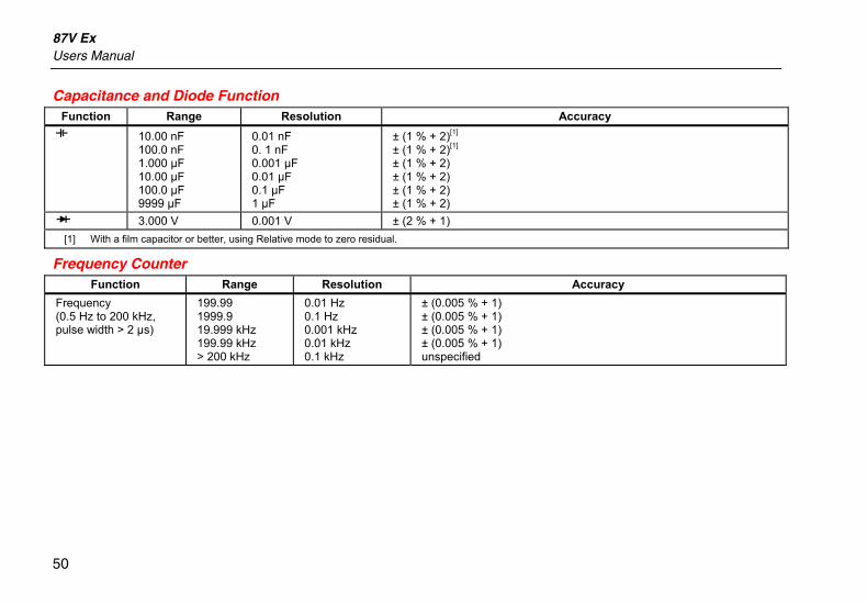
Capacitance and Diode Function Function Range Resolution Accuracy E 10.00 nF
100.0 nF 1.000 µF 10.00 µF 100.0 µF 9999 µF
0.01 nF 0. 1 nF 0.001 µF 0.01 µF 0.1 µF 1 µF
± (1 % + 2)[1] ± (1 % + 2)[1] ± (1 % + 2) ± (1 % + 2) ± (1 % + 2) ± (1 % + 2)
G 3.000 V 0.001 V ± (2 % + 1) [1] With a film capacitor or better, using Relative mode to zero residual.
Frequency Counter Function Range Resolution Accuracy
Frequency (0.5 Hz to 200 kHz, pulse width > 2 µs)
199.99 1999.9 19.999 kHz 199.99 kHz > 200 kHz
0.01 Hz 0.1 Hz 0.001 kHz 0.01 kHz 0.1 kHz
± (0.005 % + 1) ± (0.005 % + 1) ± (0.005 % + 1) ± (0.005 % + 1) unspecified
True-rms Multimeter Detailed Specifications
51
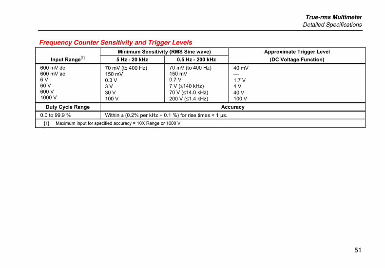
Frequency Counter Sensitivity and Trigger Levels Minimum Sensitivity (RMS Sine wave) Approximate Trigger Level
Input Range[1] 5 Hz - 20 kHz 0.5 Hz - 200 kHz (DC Voltage Function) 600 mV dc 600 mV ac 6 V 60 V 600 V 1000 V
70 mV (to 400 Hz) 150 mV 0.3 V 3 V 30 V 100 V
70 mV (to 400 Hz) 150 mV 0.7 V 7 V (≤140 kHz) 70 V (≤14.0 kHz) 200 V (≤1.4 kHz)
40 mV 1.7 V 4 V 40 V 100 V
Duty Cycle Range Accuracy 0.0 to 99.9 % Within ± (0.2% per kHz + 0.1 %) for rise times < 1 µs.
[1] Maximum input for specified accuracy = 10X Range or 1000 V.
87V Ex Users Manual
52
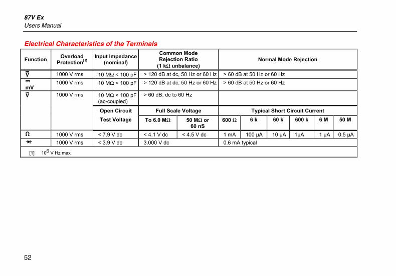
Electrical Characteristics of the Terminals
Function Overload Protection[1]
Input Impedance (nominal)
Common Mode Rejection Ratio
(1 kΩ unbalance) Normal Mode Rejection
L 1000 V rms 10 MΩ < 100 pF > 120 dB at dc, 50 Hz or 60 Hz > 60 dB at 50 Hz or 60 Hz F mV
1000 V rms 10 MΩ < 100 pF > 120 dB at dc, 50 Hz or 60 Hz > 60 dB at 50 Hz or 60 Hz
K 1000 V rms 10 MΩ < 100 pF (ac-coupled)
> 60 dB, dc to 60 Hz
Open Circuit Full Scale Voltage Typical Short Circuit Current
Test Voltage To 6.0 MΩ 50 MΩ or 60 nS
600 Ω 6 k 60 k 600 k 6 M 50 M
e 1000 V rms < 7.9 V dc < 4.1 V dc < 4.5 V dc 1 mA 100 µA 10 µA 1µA 1 µA 0.5 µA G 1000 V rms < 3.9 V dc 3.000 V dc 0.6 mA typical
[1] 106 V Hz max
True-rms Multimeter Detailed Specifications
53
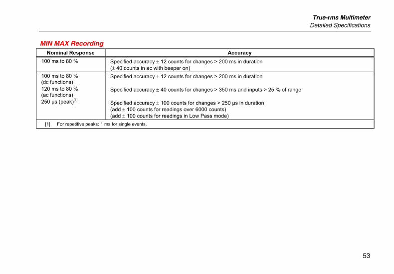
MIN MAX Recording Nominal Response Accuracy
100 ms to 80 % Specified accuracy ± 12 counts for changes > 200 ms in duration (± 40 counts in ac with beeper on)
100 ms to 80 % (dc functions) 120 ms to 80 % (ac functions) 250 µs (peak)[1]
Specified accuracy ± 12 counts for changes > 200 ms in duration Specified accuracy ± 40 counts for changes > 350 ms and inputs > 25 % of range Specified accuracy ± 100 counts for changes > 250 µs in duration (add ± 100 counts for readings over 6000 counts) (add ± 100 counts for readings in Low Pass mode)
[1] For repetitive peaks: 1 ms for single events.
87V Ex Users Manual
54
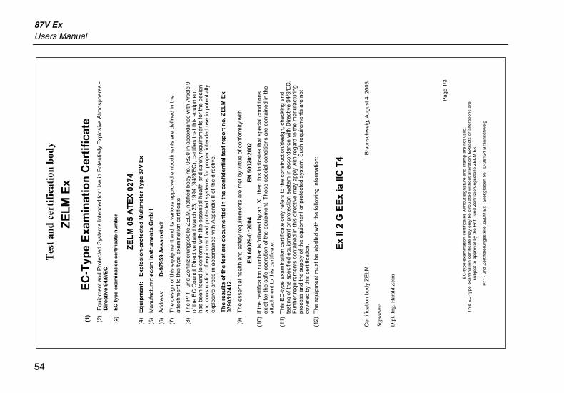
Tes
t an
d ce
rtif
icat
ion
body
ZE
LM
Ex
(1)
EC
-Typ
e E
xam
inat
ion
Cer
tifi
cate
(2)
Equ
ipm
ent a
nd P
rote
cted
Sys
tem
s In
tend
ed fo
r U
se in
Pot
entia
lly E
xplo
sive
Atm
osph
eres
-
Dir
ectiv
e 94
/9/E
C
(2)
E
C-t
ype
exam
inat
ion
cer
tifi
cate
nu
mb
er
ZE
LM
05
AT
EX
027
4 (4
) E
qu
ipm
ent:
E
xplo
sio
n-p
rote
cted
Mu
ltim
eter
Typ
e 87
V E
x
(5)
Man
ufac
ture
r: e
com
Inst
rum
ents
Gm
bH
(6)
Add
ress
: D
-979
59 A
ssam
stad
t
(7)
The
des
ign
of th
is e
quip
men
t and
its
vario
us a
ppro
ved
embo
dim
ents
are
def
ined
in th
e at
tach
men
t to
this
type
exa
min
atio
n ce
rtifi
cate
.
(8)
The
Pr
f- u
nd Z
ertif
izie
rung
sste
lle Z
ELM
, not
ified
bod
y no
. 082
0 in
acc
orda
nce
with
Art
icle
9
of th
e E
C C
ounc
il D
irect
ive
date
d M
arch
23,
199
4 (9
4/9/
EC
), c
ertif
ies
that
this
equ
ipm
ent
has
been
foun
d to
con
form
with
the
esse
ntia
l hea
lth a
nd s
afet
y re
quire
men
ts fo
r th
e de
sign
an
d co
nstr
uctio
n of
equ
ipm
ent a
nd p
rote
cted
sys
tem
s fo
r pr
oper
inte
nded
use
in p
oten
tially
ex
plos
ive
area
s in
acc
orda
nce
with
App
endi
x II
of th
e di
rect
ive.
Th
e re
sult
s o
f th
e te
st a
re d
ocu
men
ted
in t
he
con
fid
enti
al t
est
rep
ort
no
. ZE
LM
Ex
0390
5124
12.
(9)
The
ess
entia
l hea
lth a
nd s
afet
y re
quire
men
ts a
re m
et b
y vi
rtue
of c
onfo
rmity
with
EN
600
79-0
:20
04
EN
500
20:2
002
(10)
If t
he c
ertif
icat
ion
num
ber
is fo
llow
ed b
y an
X
, the
n th
is in
dica
tes
that
spe
cial
con
ditio
ns
exis
t for
the
safe
ope
ratio
n of
the
equi
pmen
t. T
hese
spe
cial
con
ditio
ns a
re c
onta
ined
in th
e at
tach
men
t to
this
cer
tific
ate.
(11)
Thi
s E
C-t
ype
exam
inat
ion
cert
ifica
te o
nly
refe
rs to
the
cons
truc
tion/
desi
gn, c
heck
ing
and
test
ing
of th
e sp
ecifi
ed e
quip
men
t or
prot
ectio
n sy
stem
in a
ccor
danc
e w
ith D
irect
ive
94/9
/EC
. F
urth
er r
equi
rem
ents
con
tain
ed in
this
dire
ctiv
e m
ay a
pply
with
reg
ard
to th
e m
anuf
actu
ring
proc
ess
and
the
supp
ly o
f the
equ
ipm
ent o
r pr
otec
ted
syst
em. S
uch
requ
irem
ents
are
not
co
vere
d by
this
cer
tific
atio
n.
(12)
The
equ
ipm
ent m
ust b
e la
belle
d w
ith th
e fo
llow
ing
info
rmat
ion:
Ex
II 2
G E
Ex
ia II
C T
4 C
ertif
icat
ion
body
ZE
LM
Bra
unsc
hwei
g, A
ugus
t 4, 2
005
Sign
atur
e D
ipl.-
Ing.
Har
ald
Zel
m
P
age
1/3
EC
-typ
e ex
amin
atio
n ce
rtifi
cate
s w
ithou
t sig
natu
re a
nd s
tam
p ar
e no
t val
id.
Thi
s E
C-t
ype
exam
inat
ion
cert
ifica
te m
ay o
nly
be c
ircul
ated
with
out a
ltera
tion.
Ext
ract
s or
alte
ratio
ns a
re
subj
ect t
o ap
prov
al b
y th
e P
rf-
und
Zer
tifiz
ieru
ngss
telle
ZE
LM E
x
Pr
f- u
nd Z
ertif
izie
rung
sste
lle Z
ELM
Ex
Sie
kgra
ben
56
D-3
8124
Bra
unsc
hwei
g
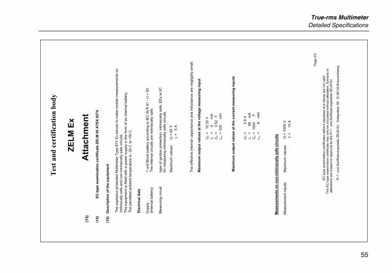
True-rms Multimeter Detailed Specifications
55
Tes
t an
d ce
rtif
icat
ion
body
ZE
LM
Ex
(13)
Att
ach
men
t (1
4)
EC
-typ
e ex
amin
atio
n c
erti
fica
te Z
EL
M 0
5 A
TE
X 0
274
(15)
D
escr
ipti
on
of
the
equ
ipm
ent
The
exp
losi
on-p
rote
cted
Mul
timet
er T
ype
87V
Ex
serv
es to
mak
e m
obile
mea
sure
men
ts o
n in
trin
sica
lly s
afe
and
non-
intr
insi
cally
saf
e ci
rcui
ts.
The
equ
ipm
ent i
s fit
ted
with
a p
ower
sup
ply
in th
e fo
rm o
f an
inte
rnal
bat
tery
. T
he p
erm
itted
am
bien
t tem
pera
ture
is -
20C
to +
50C
.
Ele
ctri
cal d
ata
Sup
ply
1 un
it B
lock
bat
tery
acc
ordi
ng to
lEC
6LR
61
- U
= 9
V
(Int
erna
l bat
tery
) T
he in
tern
al c
ircui
ts a
re in
trin
sica
lly s
afe.
Mea
surin
g ci
rcui
t ty
pe o
f ign
ition
pro
tect
ion:
intr
insi
cally
saf
e, E
Ex
ia II
C
for
mea
surin
g in
trin
sica
lly s
afe
circ
uits
Max
imum
val
ues:
The
effe
ctiv
e in
tern
al c
apac
itanc
e an
d in
duct
ance
are
neg
ligib
ly s
mal
l.
Max
imu
m o
utp
ut
valu
es a
t th
e vo
ltag
e m
easu
rin
g in
pu
t
Max
imu
m o
utp
ut
valu
es a
t th
e cu
rren
t-m
easu
rin
g in
pu
ts
Mea
sure
men
ts o
n n
on
-in
trin
sica
lly s
afe
circ
uit
s
Mea
sure
men
t inp
uts
Max
imum
val
ues:
P
age
2/3
EC
-typ
e ex
amin
atio
n ce
rtifi
cate
s w
ithou
t sig
natu
re a
nd s
tam
p ar
e no
t val
id.
Thi
s E
C-t
ype
exam
inat
ion
cert
ifica
te m
ay o
nly
be c
ircul
ated
with
out a
ltera
tion.
Ext
ract
s or
al
tera
tions
are
sub
ject
to a
ppro
val b
y th
e P
rf-
und
Zer
tifiz
ieru
ngss
telle
ZE
LM E
x
Pr
f- u
nd Z
ertif
izie
rung
sste
lle Z
ELM
Ex
Sie
kgra
ben
56
D-3
8124
Bra
unsc
hwei
g
Ui =
65
V
I i =
5
A
Uo
=
10.3
5 V
I o
=
4
mA
C
o =
2
.52
F
L o =
100
mH
Uo
=
2
.8 V
I o
=
68
mA
C
o =
100
0
F
L o =
8
mH
Ui =
100
0 V
I i
=
10
A
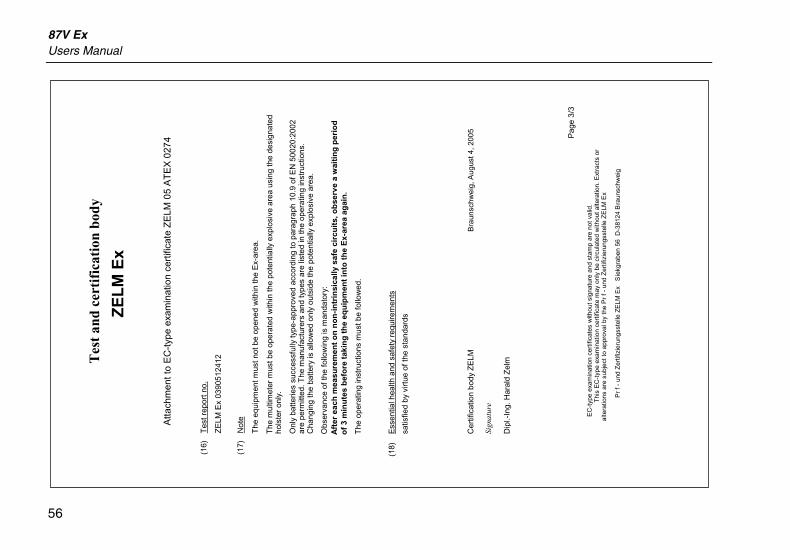
87V Ex Users Manual
56
Tes
t an
d ce
rtif
icat
ion
body
ZE
LM
Ex
Atta
chm
ent t
o E
C-t
ype
exam
inat
ion
cert
ifica
te Z
ELM
05
AT
EX
027
4
(16)
T
est r
epor
t no.
ZE
LM E
x 03
9051
2412
(17)
N
ote
The
equ
ipm
ent m
ust n
ot b
e op
ened
with
in th
e E
x-ar
ea.
The
mul
timet
er m
ust b
e op
erat
ed w
ithin
the
pote
ntia
lly e
xplo
sive
are
a us
ing
the
desi
gnat
ed
hols
ter
only
.
Onl
y ba
tterie
s su
cces
sful
ly ty
pe-a
ppro
ved
acco
rdin
g to
par
agra
ph 1
0.9
of E
N 5
0020
:200
2 ar
e pe
rmitt
ed. T
he m
anuf
actu
rers
and
type
s ar
e lis
ted
in th
e op
erat
ing
inst
ruct
ions
. C
hang
ing
the
batte
ry is
allo
wed
onl
y ou
tsid
e th
e po
tent
ially
exp
losi
ve a
rea.
Obs
erva
nce
of th
e fo
llow
ing
is m
anda
tory
: A
fter
eac
h m
easu
rem
ent
on
no
n-i
ntr
insi
cally
saf
e ci
rcu
its,
ob
serv
e a
wai
tin
g p
erio
d
of
3 m
inu
tes
bef
ore
tak
ing
th
e eq
uip
men
t in
to t
he
Ex-
area
ag
ain
.
The
ope
ratin
g in
stru
ctio
ns m
ust b
e fo
llow
ed.
(1
8)
Ess
entia
l hea
lth a
nd s
afet
y re
quire
men
ts
s
atis
fied
by v
irtue
of t
he s
tand
ards
Cer
tific
atio
n bo
dy Z
ELM
B
raun
schw
eig,
Aug
ust 4
, 200
5 Si
gnat
ure
Dip
l.-In
g. H
aral
d Z
elm
P
age
3/3
EC
-typ
e ex
amin
atio
n ce
rtifi
cate
s w
ithou
t sig
natu
re a
nd s
tam
p ar
e no
t val
id.
Thi
s E
C-t
ype
exam
inat
ion
cert
ifica
te m
ay o
nly
be c
ircul
ated
with
out a
ltera
tion.
Ext
ract
s or
al
tera
tions
are
sub
ject
to a
ppro
val b
y th
e P
rf-
und
Zer
tifiz
ieru
ngss
telle
ZE
LM E
x
Pr
f- u
nd Z
ertif
izie
rung
sste
lle Z
ELM
Ex
Sie
kgra
ben
56 D
-381
24 B
raun
schw
eig


![[XLS] · Web viewNORMA TECNICA NMX-CH-5725-6-IMNC-2006 EXACTITUD (VERACIDAD Y PREISION) DE RESUL MULTIMETRO PARA MEDICION DE CORRIENTE,GENERACION FRECUENCIA,FLUKE 87V VEHICULO TSURE](https://img.dokumen.tips/doc/110x75/5b8a7a947f8b9a78618e20ff/xls-web-viewnorma-tecnica-nmx-ch-5725-6-imnc-2006-exactitud-veracidad-y-preision.jpg)