Embed Size (px)
DESCRIPTION
NASA space hydrogen handling methods
Citation preview

NSS 1740.16
National Aeronautics and Space Administration
SAFETY STANDARD FORHYDROGEN AND HYDROGENSYSTEMSGuidelines for Hydrogen System Design, MaterialsSelection, Operations, Storage, and Transportation
Office of Safety and Mission AssuranceWashington, DC 20546

i
PREFACE
This safety standard establishes a uniform Agency process for hydrogen systemdesign, materials selection, operation, storage, and transportation. This standardcontains minimum guidelines applicable to NASA Headquarters and all NASA FieldCenters. Centers are encouraged to assess their individual programs and developadditional requirements as needed. “Shalls” and “musts” denote requirementsmandated in other documents and in widespread use in the aerospace industry.
This standard is issued in loose-leaf form and will be revised by change pages.
Comments and questions concerning the contents of this publication should bereferred to the National Aeronautics and Space Administration Headquarters,Director, Safety and Risk Management Division, Office of the Associate for Safetyand Mission Assurance, Washington, DC 20546.
Frederick D. Gregory Effective Date: Feb.12, 1997Associate Administrator for
Safety and Mission Assurance

iii
ACKNOWLEDGMENTS
The NASA Hydrogen Safety Handbook originally was prepared by Paul M. Ordin,Consulting Engineer, with the support of the Planning Research Corporation. Thesupport of the NASA Hydrogen-Oxygen Safety Standards Review Committee inproviding technical monitoring of the standard is acknowledged. The committeeincluded the following members:
William J. Brown (Chairman) NASA Lewis Research CenterCleveland, OH
Harold Beeson NASA Johnson Space CenterWhite Sands Test FacilityLas Cruces, NM
Mike Pedley NASA Johnson Space CenterHouston, TX
Dennis Griffin NASA Marshall Space Flight CenterAlabama
Coleman J. Bryan NASA Kennedy Space CenterFlorida
Wayne A. Thomas NASA Lewis Research CenterCleveland, OH
Wayne R. Frazier NASA HeadquartersWashington, DC
The special contributions provided by Grace Ordin are noted. Also acknowledgedare the contributions provided by Carol A. Vidoli and, particularly, William J.Brown of NASA Lewis Research Center for their aid in reviewing, organizing, andediting this handbook; Fred Edeskuty of Los Alamos National Laboratory forinformation on slush hydrogen, and William Price of Vitro Corporation for hisrevision. This revision was prepared and edited by personnel at the NASA JohnsonSpace Center White Sands Test Facility. This document was extensively reviewedby experts at the various NASA centers, and their comments and suggections wereinstrumental in making the manual as complete and accurate as possible. Theexpertise of these professionals in the area of hydrogen system hazards, materials,selection, design, and operation is gratefully acknowledged.

v
ABOUT THIS DOCUMENT
This document and its companion document, Safety Standard for Oxygen andOxygen Systems (NSS 1740.15 1996), are identified as Tier 2 Standards andTechnical Requirements in the NASA Safety and Documentation Tree (NHB 1700.11993). The information presented is intended as a reference to hydrogen design andpractice and not as an authorizing document. The words “shall” and “must” areused in this document to indicate a mandatory requirement, and the authority for therequirement is given. The words “should” and “will” are used to indicate arecommendation or that which is advised but not mandatory.
The information is arranged in an easy-to-use format. The reader will find thefollowing useful to note:
• A numbered outline format is used so information can be readily found andeasily cited.
• An index is provided in Appendix H to assist the reader in locating informationon a particular topic.
• Acronyms are defined when introduced, and a tabulation of acronyms used in thedocument is provided in Appendix F.
• The figures and tables referenced in the text are located in the appendices.
• All sources are referenced so the user can verify original sources as deemednecessary. References cited in the main body of the text can be found inChapter 10, and references introduced in an appendix is cited in that appendix.The latest revisions of codes, standards, and NASA directives should be usedwhen those referenced are superseded.
• The International System of Units (SI) is used for primary units, and USCustomary units are given in parentheses following the SI units. Some of thetables and figures contain only one set of units.

vii
TABLE OF CONTENTS
Paragraph Page
CHAPTER 1: BASIC HYDROGEN SAFETY GUIDELINES
100 SCOPE 1-1
101 INTRODUCTION 1-1
102 APPLICABLE DOCUMENTS 1-5
103 PERSONNEL TRAINING 1-5
104 USE OF INHERENT SAFETY FEATURES 1-7
105 CONTROLS 1-9
106 FAIL-SAFE DESIGN 1-10
107 SAFETY 1-10
108 WAIVER PROVISIONS 1-11
CHAPTER 2: PROPERTIES AND HAZARDS OF HYDROGEN
200 TYPICAL PROPERTIES 2-1
201 TYPES OF HAZARDS 2-3
202 FLAMMABILITY AND IGNITION OF HYDROGEN 2-14
203 DETONATION 2-24
204 CHARACTERISTIC PROPERTIES OF GH2 2-29
205 CHARACTERISTIC PROPERTIES OF LH2 2-35
206 CHARACTERISTIC PROPERTIES OF SLH2 2-36
CHAPTER 3: MATERIALS FOR HYDROGEN SERVICE
300 CONSIDERATIONS FOR MATERIALS SELECTION 3-1
301 HYDROGEN EMBRITTLEMENT 3-7
302 THERMAL CONSIDERATIONS IN MATERIALS SELECTION 3-11
CHAPTER 4: HYDROGEN FACILITIES
400 SAFETY POLICY 4-1
401 SAFETY REVIEWS 4-2
402 GENERAL FACILITY GUIDELINES 4-6

viii
TABLE OF CONTENTS (continued)
Paragraph Page
403 BUILDINGS AND TEST CHAMBERS 4-12
404 CONTROL ROOMS 4-18
405 LOCATION AND QUANTITY-DISTANCE GUIDELINES 4-19
406 EXCLUSION AREAS 4-29
407 PROTECTION OF HYDROGEN SYSTEMS AND
SURROUNDINGS 4-32
408 FIRE PROTECTION 4-36
409 DOCUMENTATION, TAGGING, AND LABELING OF
STORAGE VESSELS, PIPING, AND COMPONENTS 4-39
410 INSTRUMENTATION AND MONITORING 4-42
411 EXAMINATION, INSPECTION, AND RECERTIFICATION 4-46
CHAPTER 5: HYDROGEN STORAGE VESSELS, PIPING, ANDCOMPONENTS
500 GENERAL REQUIREMENTS 5-1
501 STORAGE VESSELS 5-3
502 PIPING SYSTEMS 5-15
503 COMPONENTS 5-25
504 OVERPRESSURE PROTECTION OF STORAGE VESSELS AND
PIPING SYSTEMS 5-43
505 HYDROGEN VENT AND FLARE SYSTEMS 5-49
506 CONTAMINATION 5-55
507 VACUUM SYSTEM 5-60
CHAPTER 6: HYDROGEN AND HYDROGEN FIRE DETECTION
600 HYDROGEN DETECTION 6-1
601 HYDROGEN FIRE DETECTION SYSTEMS 6-9
CHAPTER 7: OPERATING PROCEDURES
700 GENERAL POLICY 7-1

ix
TABLE OF CONTENTS (continued)
Paragraph Page
701 STORAGE AND TRANSFER PROCEDURES 7-10
CHAPTER 8: TRANSPORTATION
800 GENERAL 8-1
801 TRANSPORT ON PUBLIC THOROUGHFARES 8-3
802 TRANSPORT ON SITE CONTROLLED THOROUGHFARE 8-6
803 TRANSPORTATION EMERGENCIES 8-10
CHAPTER 9: EMERGENCY PROCEDURES
900 GENERAL 9-1
902 TYPES OF EMERGENCIES 9-4
902 ASSISTANCE IN EMERGENCIES 9-10
903 FIRE SUPPRESSION 9-11
904 FIRST-AID PROCEDURES FOR CRYOGENIC-INDUCED
INJURIES 9-15
905 SAFEGUARDS FOR ENTERING PERMIT-REQUIRED
CONFINED SPACES 9-16
CHAPTER 10: REFERENCES
APPENDIX A: TABLES AND FIGURES A-1
APPENDIX B: ASSESSMENT EXAMPLES B-1
APPENDIX C: SCALING LAWS, EXPLOSIONS, BLAST EFFECTS, AND
FRAGMENTATION C-1
APPENDIX D: CODES, STANDARDS, AND NASA DIRECTIVES D-1
APPENDIX E: RELIEF DEVICES E-1
APPENDIX F: ABBREVIATIONS AND ACRONYMS F-1
APPENDIX G: GLOSSARY G-1
APPENDIX H: INDEX H-1

x
LIST OF FIGURES
Figures Page
A1.1 Equilibrium Percentage of Para-hydrogen vs. Temperature A-3
A1.2 Enthalpy of Normal Hydrogen Conversion A-4
A1.3 Vapor Pressure of Liquefied Para-hydrogen (TP to NBP) A-5
A1.4 Vapor Pressure of LH2 (NBP to CP) A-6
A1.5 Vapor of Normal and Para-hydrogen Below the Triple Point A-7
A1.6 Comparison of densities and bulk Fluid Heat Capacities for Slush,Triple-Point liquid, and NBP Liquid Para-hydrogen A-8
A1.7 Proposed Phase Diagram (P-T) for Solid Hydrogen at VariousOtho-hydrogen Mole Fractions A-9
A1.8 Proposed Phase Diagram (V-T Plane) for Solid Normal Hydrogen A-10
A1.9 Specific Heat (Heat Capacity) of Saturated Solid Hydrogen A-11
A1.10 Melting Line from Triple Point to Critical Point Pressurefor Para-hydrogen A-12
A2.1 Flammability Limits at a Pressure of 101.3 kPa (14.7 psia)and a Temperature of 298 K (77 °F) A-37
A2.2 Effects of N2, He, CO2, and H2O Diluents on FlammabilityLimits of Hydrogen in Air at 101.3 kPa (14.7 psia) A-38
A2.3 Effects of Halocarbon Inhibitors on Flammability Limits ofHydrogen-Oxygen Mixtures at a Pressures of 101.3 kPa (14.7 psia)and a Temperature of 298 K (77 °F) A-39
A2.4 Distance for Fireball Radiation Flux Induced Third Degree Burnsper Amount of Fuel Burned at a Thermal Radiation Intensityof 134 kJ/m2 (11.8 Btu/ft2) A-40
A2.5 Radiation Intensity as a Function of Exposure Time or Escape Time A-41

xi
LIST OF FIGURES (continued)
Figures Page
A2.6 Variation in Distance from a Hydrogen Fire for a Thermal RadiationExposure of 2 cal/cm2 for an Exposure Duration of 10 s A-42
A2.7 Minimum Dimensions of GH2-Air Mixtures for Detonation at101.3 kPa (14.7 psia) and 298 K (77 °F) A-43
A2.8 Detonation Cell Widths for Hydrogen-Air Mixtures at101.3 kPa (14.7 psia) A-44
A2.9 Minimum Initiation Energies for Direct Detonation ofHydrogen-Air Mixtures A-45
A4.1 Flame Dip as a Function of Stack Diameter an Hydrogen Flow A-65
A4.2 Blowout and Stable Flame Region A-66
A4.3 Flame Shape in Crosswinds A-67
A4.4 Minimum Flow Rate for Non-Stratified, Two Phase Hydrogen andNitrogen Flow for Pipeline Fluid Qualities Below 95% and 98% A-68
A4.5 Liquid Hydrogen Flow Rate Limits to Avoid Excessive CooldownStresses in Thick-wall Piping Sections Such as Flanges for 304 SSand 6061 Al A-69
A4.6 Liquid Nitrogen Flow Rate Limits to Avoid Excessive CooldownStresses in Thick-wall Piping Sections Such as Flanges for 304 SSand 6061 Al A-70
A5.1 Charpy Impact Strength as a Function of Temperature forVarious Materials A-75
A5.2 Yield and Tensile Stress of 5086 Aluminum as a Function ofTemperature A-76
A5.3 Yield and Tensile Stress of AISI 430 Stainless Steel as a Functionof Temperature A-77
A5.4 Thermal Expansion Coefficient of Copper as a Functionof Temperature A-78
xii
LIST OF FIGURES (continued)
Figures Page
A5.5 Total Linear Thermal Contraction as a Function of Temperaturefor Several Materials A-79
A6.1 Irradiance of Common IR Sources A-93
A6.2 Atmospheric IR Transmission and H2-Air-Flame Emission A-94
A6.3 UV/VIS/Near-IR Emissions A-95
A6.4 Flame Components A-95

xiii
LIST OF TABLES
Tables Page
A1.1 Selected Thermophysical, Chemical, and Combustion Propertiesof Gaseous, Liquefied, Slush and Solid Para-hydrogen A-13
A1.2 Fixed Point Properties of Normal Hydrogen A-17
A1.3 Thermodynamic Properties of the Hydrogen Solid-Vapor TwoPhase Region A-19
A1.4 Thermodynamic Properties of the Hydrogen Solid-Liquid TwoPhase Region A-20
A1.5 Molar Volume of Compressed Solid Para-hydrogen A-21
A1.6 Thermal Expansion of Solid Para-hydrogen A-22
A2.1 Potential Ignition Sources A-46
A2.2 Flammability Limits A-47
A2.3 Effects of Diluents on Flammable Range for Hydrogen in Air A-48
A2.4 Inhibitor for Extinction of Hydrogen Diffusion Flames A-49
A2.5 Critical Radiant Flux Levels A-50
A3.1 Order of Preference for Location of GH2 Storage Systems A-53
A3.2 Quantity-Distance Requirements for Nonpropellant GH2 Systemsfor Outdoor Locations A-54
A3.3 Order of Preference for Locations of LH2 Storage Systems A-55
A3.4 Quantity-Distance Requirements for Nonpropellant LH2 Systemsfor Outdoor Locations A-56
A3.5 Liquid Propellant Hazard and Compatibility Groups A-57
A3.6 Explosive Equivalent Factors for Liquid Propellants A-58
A3.7 Safe Quantity-Distance Relationships for LH2 Storage for Hazard

xiv
Group III Materials A-59

xv
LIST OF TABLES (continued)
Tables Page
A3.8 Separation and Intraline Quantity-Distance Values forMixed Propellants A-61
A4.1 Summary of Liquefied Hydrogen Spill Data A-71
A5.1 Summary of Material Compatibility for Hydrogen Service A-80
A5.2 A Selection of Recommended Materials for Typical Applications A-81
A5.3 Minimum Temperatures and Basic Allowable Stresses in Tensionfor Selected Metals A-82
A5.4 Elastic Properties of Selected Materials at Room Temperature andLiquid Hydrogen Temperature A-84
A5.5 Mechanical Properties of Selected Materials at Room Temperatureand Liquid Hydrogen Temperature A-85
A5.6 Thermal Properties of Selected Materials at Room Temperature andLiquid Hydrogen Temperature A-86
A5.7 Typical Characteristics of Hydrogen Embrittlement Types A-87
A5.8 Susceptibility of Materials to Embrittlement in Hydrogen at10,000 psi and 72 °F A-88
A5.9 Comparison Effects of Air, Helium, and Hydrogen Exposure onSelected Aluminum, Nickel, and Copper Alloys A-89
A6.1 Typical Hydrogen Gas Detectors A-96
A6.2 A Survey and Analysis of Commercially Available Hydrogen Sensors A-97
A6.3 Sensitivity Limits of Hydrogen Detectors A-98
A6.4 Typical Hydrogen Fire Detectors A-99
A7.1 Hydrogen Accidents - Industrial A-103
A7.2 Hydrogen Accidents - Ammonia Plants A-104

xvi
LIST OF TABLES (continued)
Tables Page
A7.3 Hydrogen Accidents - Aerospace A-105
B1 Detonation Pressures and Temperatures B-2
B2 Deflagration Pressures B-4
B3 Liquid-Lockup Pressure Change B-6
B4 Minimum Separation Distances for Siting the LH2 Dewar inExample 6 B-20
D1 Selection of Federal Regulations for Hydrogen Transportation D-17
E1 Considerations for Relief Devices in LH2 Pipelines E-6

1-1
CHAPTER 1: BASIC HYDROGEN SAFETY GUIDELINES
Note: Hydrogen shall be stored, handled, and used so life and health arenot jeopardized and the risk of property damage is minimized.
100 SCOPE
This handbook is a central agency document containing guidelines for safelystoring, handling, and using hydrogen in gaseous, liquid, or slush form,whether used as a nonpropellant or propellant. Each designer, user,operator, maintainer, assurance person, and designated project manager isresponsible for incorporating the appropriate requirements of this guidelinedocument into their projects or facilities. However, use of this guidelinedocument does not relieve the designer, user, operator, maintainer, andassurance person and designated managers of professional responsibility orallow them to preclude the exercise of sound engineering judgment.
101 INTRODUCTION
a. General.
(1) The purpose of the Hydrogen Safety Handbook is to provide apractical set of guidelines for safe hydrogen use. For thepurposes of this handbook, hydrogen may refer to the gaseous(GH2), to the liquefied (LH2), and/or slush (SLH2) form.Specific or special considerations for each form will bedelineated. This handbook contains chapters on properties andhazards, facility design, design of components, materialscompatibility, detection, and transportation. It also coversvarious operational issues and emergency procedures. Theintent of this handbook is to provide enough information that itcan be used alone, but at the same time, reference data sourcesthat can provide much more detail if required. Anyinformation contained herein on hazards and use of hydrogenis based on current knowledge and is subject to change asmore testing is completed and evaluated.
(2) Federal and state mandatory regulation shall take precedenceover NASA directives in the event of conflicting requirements.A primary policy of NASA is that when requirements conflict,the most stringent shall apply (NSS 1740.11 1993).
101a

1-2
101b
b. Nonpropellant Use.
The following standards apply and shall be followed for hydrogenused as a nonpropellant:
(1) 29 CFR 1910.119 (1996) sets requirements for hazard analysisfor systems involving 4535 kg (10,000 lb) or more ofhydrogen in any form.
(2) 29 CFR 1910.103 (1996) sets requirements for GH2 systems.This regulation does not apply to single GH2 systems usingcontainers having a total hydrogen content of less than 11 CM(400 CF), measured at 101.3 kPa (14.7 psia) and 294.1 K(70 °F). The regulation shall apply where individual systems,each having a total hydrogen content of less than 11 CM(400 CF), are located less than 1.5 m (5 ft) from each other.
(3) 29 CFR 1910.103 (1996) sets requirements for LH2 systems.This regulation does not apply to portable containers having atotal LH2 content of less than 150 L (39.63 gal), nor to a LH2
system with a content greater than 283,910 L (75,000 gal).
(4) All pressure vessels for hydrogen service shall be designed,constructed, and tested in accordance with ASME Boiler andPressure Vessel Code (BPVC) (1995) and NMI 1710.3(1994), NSS/HP 1740.1 (1974), and NSS 1740.4 (1976). Theappropriate standards from these codes shall be used foraerospace pressure vessels. All piping systems for hydrogenservice shall be designed, constructed, and tested inaccordance with ANSI/ASME B31.1 (1995) andANSI/ASME B31.3 (1996) as appropriate.
c. Propellant Use.
The following standards and guidelines apply and shall be followedfor LH2 used as a propellant:
(1) 29 CFR 1910.119 (1996) sets requirements for hazard analysisfor systems involving 4535 kg (10,000 lb) or more ofhydrogen in any form.

1-3
(2) 29 CFR 1910.103 (1996) sets requirements for LH2 systemsexcept for the requirements for quantity and distance sitingand for personnel monitoring.
(3) NSS 1740.12 (1993)(DoD 6055.9 1992) sets requirements forsiting LH2 storage in relation to facilities and other propellantsand chemical storage and for personnel monitoring.
(4) All pressure vessels for hydrogen service shall be designed,constructed, and tested in accordance with ASME BPVC(1995) and NMI 1710.3 (1994), NSS/HP 1740.1 (1974), andNSS 1740.4 (1976). The appropriate standards from thesecodes shall be used for aerospace pressure vessels. All pipingsystems for hydrogen service shall be designed, constructed,and tested in accordance with ANSI/ASME B31.3 (1996).
d. SLH2 and Solid Hydrogen.
No standards specifically apply to SLH2 and solid hydrogen atpresent. It is suggested that when the total mass of these materials inthe system being considered is equivalent to the amounts cited in101.b(1) and 101.b(3) that these reference standards be applied.Except for supplying limited property data in Appendix A1, solidhydrogen is not discussed further.
e. Minimum Quantities.
The authority having jurisdiction (AHJ) at the controlling NASAcenter is responsible and shall establish requirements for safe storageand use that shall protect all personnel and facilities, for hydrogensystems in quantities below the minimum quantity specified in theabove standards and guidelines.
f. Other Facilities.
Those facilities, equipment, and test articles that do not meet thedefinitions of GH2 or LH2 systems as stated in the standards andguidelines above but are in hydrogen service shall have applied fortheir design, construction, testing, and use 29 CFR 1910.103 (1996),29 CFR 1910.119 (1996), NSS 1740.12 (1993), and other standardsas directed by the AHJ at the controlling NASA center.
101f

1-4
101g
g. Retroactivity.
(1) An existing system for hydrogen used as a nonpropellant notin strict compliance with the provisions of these standards andguidelines shall be permitted to be continued in use wheresuch use does not constitute a distinct hazard to life oradjoining facilities (NFPA 50A 1994 and NFPA 50B 1994).
(2) Existing facilities for LH2 used as a propellant not incompliance with current standards may continue to be used forthe balance of their functional lives, as long as currentoperations present no significantly greater risk than thatassumed when the facility was originally designed, and it canbe demonstrated clearly that a modification to bring thefacility into compliance is not feasible. However, the facilitymust be brought into compliance with current standards (NSS1740.12 1993) in the case of a major renovation.
102 APPLICABLE DOCUMENTS
Information on safe use of hydrogen systems is cited in each section. Unlessotherwise specified, the latest revision of documentation shall be used. Thelatest revision applies in the event of conflict. Unit conversions areconsistent with ANSI/IEEE Std 268 (1992).
103 PERSONNEL TRAINING
a. Hydrogen Handling Training.
Personnel handling hydrogen or designing equipment for hydrogensystems must become familiar with the physical, chemical, andspecific hazardous properties of GH2, LH2, and SLH2. Trainingshould include detailed safety programs that recognize humancapabilities and limitations. The goal of the safety program is toeliminate accidents and to minimize the severity of accidents thatoccur (NHB 1700.1 1993). Appendix B, Example 12 provides asummary of typical information that may be presented intraining/certification of liquid hydrogen handlers.

1-5
b. Designer Training.
Personnel involved in equipment design and operations planning mustbe trained to carefully adhere to accepted standards and guidelines andcomply with the regulatory codes (NHB 1700.1 1993).
c. Operator Certification.
Operators must be certified for handling GH2, LH2, and SLH2, asappropriate, and in the emergency procedures for spills and leaks.Operators must be kept informed of any changes in safety proceduresand facility operations (NHB 1700.1 1993 and 29 CFR 1910.1031996).
d. Hazard Communication Program.
The AHJ at the controlling NASA center shall develop, implement,and maintain at the workplace a written hazard communicationsprogram for their workplaces (29 CFR 1910.1200 1996).
e. Annual Review.
Each NASA installation will annually review all operations beingperformed at the installation to ensure that the safety training programis working effectively and to identify and enter into the program allpotentially hazardous jobs in addition to jobs designated mandatory.Employee safety committees, employee representatives, and otherinterested groups should be provided an opportunity to assist in theidentification process (NHB 1700.1 1993).
104 USE OF INHERENT SAFETY FEATURES
a. Hazards Elimination.
Regardless of quantity, all hydrogen systems and operations must bedevoid of hazards by providing adequate ventilation, designing andoperating to prevent leakage, and eliminating potential ignitionsources.
b. Barriers.
Barriers or safeguards should be provided to minimize risks andcontrol failures.
104b

1-6
104c
c. Safety Systems.
Safety systems should be installed to detect and counteract or controlthe possible effects of such hazards as vessel failures, leaks and spills,embrittlement, collisions during transportation, vaporization systemfailures, ignitions, fires and explosions, cloud dispersions, and theexposure of personnel to cryogenic or flame temperatures.
d. Safe Interface.
A safe interface must be maintained under normal and emergencyconditions so at least two failures occur before hazardous events couldlead to personal injury, loss of life, or major equipment or propertydamage.
105 CONTROLS
a. Warning Systems.
Warning systems should be installed to detect abnormal conditions,measure malfunctions, and indicate incipient failures. Warningsystem data transmissions with visible and audible signals should havesufficient redundancy to prevent any single-point failure fromdisabling the system.
b. Flow Controls.
Safety valving and flow regulation should be installed to adequatelyrespond for protection of personnel and equipment during hydrogenstorage, handling, and use.
c. Safety Features.
System and equipment safety features should be installed toautomatically control the equipment required to reduce the hazardssuggested by the triggering of the caution and warning systems.Manual controls within the systems should be constrained byautomatic limiting devices to prevent over-ranging.

1-7
106 FAIL-SAFE DESIGN
a. Certification.
The equipment, power, and other system services shall be verified forsafe performance in the design and normal operational regimesthrough certification.
b. Fail-Safe Design.
Any failure from which potentially hazardous conditions are a riskshall cause the system to revert to conditions that will be safest forpersonnel and with the lowest property damage potential.
c. Redundant Safety.
Redundant safety features shall be designed to prevent a hazardouscondition when a component fails.
107 SAFETY
a. Safety Review.
All plans, designs, and operations associated with hydrogen use mustbe subject to an independent, safety review in accordance with NHB1700.1 (1993). Safety reviews should be conducted on effects offluid properties, training, escape and rescue, fire detection, and firefighting.
b. Operating Procedures.
Operating procedures for normal and emergency conditions shall beestablished and reviewed as appropriate (NHB 1700.1 1993).
c. Hazards Analysis.
Hazards analyses must be performed to identify conditions that maycause injury, death, or property damage.
107c

1-8
107d
d. Mishap Reporting.
Reporting, investigating, and documenting the occurrences, causes,and corrective action required for mishaps, incidents, test failures,and mission failures shall follow established basic policy proceduresand guidelines (NMI 8621.1 1983 and NHB 1700.1 1993).
108 WAIVER PROVISIONS
Although this is a guideline handbook, it contains required safety provisionsnoted by shall and must. The actions indicated are required by standards andregulations and are to be followed to prevent loss of life, injury, or propertydamage. Waivers to required safety provisions shall be handled and reviewedin accordance with local procedures consistent with NHB 1700.1 (1993).NASA variances, deviations, or waivers do not apply to Federal andapplicable state and local regulations (NHB 1700.1 1993).
Actions specified by should are recommended guidelines and also denoteadditional safety considerations.
2-1
CHAPTER 2: PROPERTIES AND HAZARDS OF HYDROGEN
Note: Hydrogen is an equilibrium mixture of ortho-hydrogen and para-hydrogen. These molecules have slightly different physical properties butare chemically equivalent; therefore, the hazards associated with the useof hydrogen are the same irrespective of the molecular form.
TYPICAL PROPERTIES
a. Ortho- and Para-Hydrogen.
The hydrogen molecule exists in two forms, distinguished by therelative rotation of the nuclear spin of the individual atoms in themolecule. Molecules with spins in the same direction (parallel) arecalled ortho-hydrogen; and those with spins in the opposite direction(antiparallel), para-hydrogen. Figure A1.1 shows that the ortho-hydrogen will convert to para-hydrogen as the temperature ofhydrogen is lowered. The equilibrium mixture of ortho- and para-hydrogen at any temperature is referred to as equilibrium hydrogen.The equilibrium ortho-para-hydrogen mixture with a content of75 percent ortho-hydrogen and 25 percent para-hydrogen at roomtemperature is called normal hydrogen. The ortho-para-hydrogenconversion is accompanied by a release of heat, 703 J/g(302.4 Btu/lb) at 20 K (-423 °F) for ortho- to para-hydrogenconversion, or 527 J/g (226.7 Btu/lb) for normal to para-hydrogenconversion (Figure A1.2). Unless catalyzed, this conversion is slowbut occurs at a finite rate (taking several days to complete) andcontinues even in the solid state. Catalysts are used to accelerate thisconversion in LH2 production facilities, which produce almost purepara-hydrogen liquid (≥95 percent). Be aware of some propertydifferences in these different forms of hydrogen and observe forwhich form the data are given.
b. Slush Hydrogen.
SLH2 is a mixture of solid and LH2 at the triple point temperature.Properties of a 50 percent by mass solid or 50 percent by volumesolid mixture usually are given; although, other mass (or volume)fraction mixtures of solid and liquid are possible.
200b

2-2
200c
c. Hydrogen Properties.
Selected thermophysical properties of various states of hydrogen,primarily para-hydrogen, are given in the figures and tables inAppendix A1. McCarty, Hord, and Roder (1981) provide anextensive tabulation of the thermophysical properties of hydrogen.Figure A1.3 shows the vapor pressure of liquefied para-hydrogen as afunction of temperature from the triple point to the normal boilingpoint (NBP), and Figure A1.4 shows it from the NBP to the criticalpoint. Figure A1.5 gives the vapor pressure of para-hydrogen andnormal hydrogen below the triple point. Figure A1.6 gives thedielectric constant of various states of para-hydrogen. Figure A1.7gives a comparison of the densities and bulk fluid heat capacities forslush, triple-point liquid, and normal boiling liquid para-hydrogen.Figure A1.8 shows a proposed phase diagram (P-T plane) for solidhydrogen at various ortho mole fractions. Figure A1.9 gives aproposed phase diagram (V-T plane) for solid normal hydrogen.Figure A1.10 shows the specific heat (heat capacity) of saturated solidhydrogen. Figure A1.11 gives the melting line from the triple pointto the critical point pressure for para-hydrogen. Table A1.1 givesselected thermophysical, chemical, and combustion properties ofpara-hydrogen. This table presents property data for gaseous, liquid,slush, and solid phases. Table A1.2 gives some fixed point propertiesof normal hydrogen. Table A1.3 gives a tabulation ofthermodynamic properties of the hydrogen solid-vapor two-phaseregion, and Table A1.4 gives a tabulation of the thermodynamicproperties of the hydrogen solid-liquid two-phase region. Table A1.5gives some data on the molar volume of compressed solid para-hydrogen. Table A1.6 gives the thermal expansion coefficient ofsolid para-hydrogen from 1 to 13.8 K (-458 to -435 °F).
d. Health Hazard Properties.
Hydrogen is nontoxic, classified as a simple asphyxiant, and has nothreshold limit value (TLV). Hydrogen is not listed as a carcinogenby the National Toxicology Program, International Agency Researchon Cancer, or Occupational Safety and Health Administration.Health hazard data are given in a hydrogen Material Safety DataSheet (MSDS) in Appendix A1, Addendum.

2-3
201 TYPES OF HAZARDS
a. General.
The hazards associated with the use of hydrogen can be characterizedas physiological (frostbite, respiratory ailment, and asphyxiation),physical (phase changes, component failures, and embrittlement), andchemical (ignition and burning). A combination of hazards occur inmost instances. The primary hazard associated with any form ofhydrogen is inadvertently producing a flammable or detonablemixture, leading to a fire or detonation. Safety will be improvedwhen the designers and operational personnel are aware of thespecific hazards associated with the handling and use of hydrogen.Hazards of hydrogen use are discussed below.
b. Industrial and Aerospace Accidents.
(1) Industrial and aerospace accidents from the use of hydrogenhave occurred. Tables A7.1 through A7.3 list types ofaccidents. Analyses of these accidents indicate the followingfactors are of primary importance in causing system failures:
(a) Mechanical failure of the containment vessel, piping,or auxiliary components (brittle failure, hydrogenembrittlement, or freeze-up)
(b) Reaction of the fluid with a contaminant (such as air ina hydrogen system)
(c) Failure of a safety device to operate properly
(d) Operational error
(2) Analyses of accidents have shown that the response, throughdesign or operating procedures, to a failure should be such thata single failure does not lead to a series of failures or a chainreaction of failures; such as, any failure must be restricted to alocal event; otherwise, the hazard and potential for damage isgreatly enhanced.
201b

2-4
201c
c. Ignition.
Fires and explosions have occurred in various components ofhydrogen systems as a result of a variety of ignition sources. Ignitionsources have included mechanical sparks from rapidly closing valves,electrostatic discharges in ungrounded particulate filters, sparks fromelectrical equipment, welding and cutting operations, catalystparticles, and lightning strikes near the vent stack. Table A2.1 listsadditional ignition sources.
d. Fire and Explosions.
A potential fire hazard always exists when hydrogen is present.
(1) GH2 diffuses rapidly with air turbulence increasing the rate ofGH2 dispersion. Evaporation can rapidly occur in an LH2
spill; resulting in a flammable mixture forming over aconsiderable distance. Although ignition sources may not bepresent at the leak or spill location, fire could occur if themovement of the flammable mixture causes it to reach anignition source.
Example: Observation alone is not a reliable technique fordetecting pure hydrogen-air fires or assessing theirseverity. A fire resulted from an accident in whicha small leak developed. The equipment wasshutdown and the flame appeared to diminish;however, molten metal drippings from theequipment indicated a more severe fire was inprogress.
(2) A deflagration could result if a mixture within flammabilitylimits is ignited at a single point.
(3) A detonation could occur if the GH2-air mixture is withindetonability limits and an appropriate energy source isavailable. A deflagration could transform into a detonation ifthere is confinement or a mechanism for flame acceleration.
(4) Flash fires or boiling liquid expanding vapor explosions(BLEVE) could occur when an external source of thermalenergy is heating LH2 or SLH2 and there is a path to thesurroundings.

2-5
e. Leaks.
Leaks can occur within a system or to the surroundings. Hazards canarise by air or contaminants leaking into a cold hydrogen system (LH2
or SLH2), such as by cryo-pumping. Leaks are usually caused bydeformed seals or gaskets, valve misalignment, or failures of flangesor equipment. A leak may cause further failures of constructionmaterials. For leaks involving LH2, vaporization of cold vaporhydrogen to the atmosphere may provide a warning because moisturecondenses and forms a fog. Undetected hydrogen leaks can lead tofires and explosions.
Example: Hydrogen leaks generally originate from valves, flanges,diaphragms, gaskets, and various types of seals and fittings.The leaks usually are undetected because of the absence of acontinuous hydrogen monitor in the area. An example ofthis condition was a large sphere partitioned by a neoprenediaphragm with hydrogen stored under the diaphragm andair above it. An explosion-proof fan was placed on top ofthe sphere to provide a slight positive pressure on thediaphragm. A violent explosion occurred in the sphereafter the plant was shutdown. Hydrogen leaked past thediaphragm when the fan was turned off. Ignition wasattributed to an electrostatic discharge cause by motion ofthe diaphragm or a source associated with theexplosion-proof fan. The explosion could have beenavoided by using an inert gas instead of air across thediaphragm or monitoring the hydrogen concentration in theupper hemisphere.
f. Hydrogen Dispersion.
A property of hydrogen that tends to limit the horizontal spread ofcombustible mixtures from a hydrogen spill is its buoyancy.Although saturated hydrogen is heavier than air at the temperaturesexisting after evaporation from a spill, it quickly becomes lighter thanair, making the cloud positively buoyant. The dispersion of the cloudis affected by wind speed and wind direction and can be influenced byatmospheric turbulence and nearby structures. Although condensingmoisture is an indication of cold hydrogen, the fog shape does notgive an accurate description of the hydrogen cloud location(Witcofsky and Chirivella 1982). The use of dikes or barricades
201f

2-6
201f
around hydrogen storage facilities should be carefully examinedbecause it is preferred to disperse any leaked or spilled LH2 or SLH2
as rapidly as possible. Dikes or berms generally should not be usedunless their purpose is to limit or contain the spread of a liquid spillbecause of nearby buildings, ignition sources, etc. However, suchconfinement may delay the dispersion of any spilled liquid by limitingthe evaporation rate, and could effect a combustion event that mightoccur.
g. Storage Vessel Failure.
The release of GH2 or LH2 may result in ignition and combustion,causing fires and explosions. Damage may extend over considerablywider areas than the storage locations because of hydrogen cloudmovement. Vessel failure may be started by material failure,excessive pressure caused by heat leak, or failure of thepressure-relief system.
h. Vent and Exhaust System.
Vent and exhaust system accidents are attributed to inadequateventilation and the inadvertent entry of air into the vent. Backflow ofair can be prevented with suitable vent stack designs, provision ofmakeup air (or adequate supply of inert gas as the situation demands),check valves, or molecular seals.
i. Purging.
Pipes and vessels should be purged with an inert gas before and afterusing hydrogen in the equipment. Nitrogen may be used if thetemperature of the system is above 80 K (-316 °F), whereas, heliumshould be used if the temperature is below 80 K (-316 °F).Alternatively, a GH2 purge may be used to warm the system to 80 K(-316 °F) and then switch to a nitrogen purge if the system is below80 K (-316 °F); however, some condensation of the GH2 may occur ifthe system contains LH2. Residual pockets of hydrogen or the purgegas will remain in the enclosure if the purging rate, duration, orextent of mixing is too low. Tables A7.1 through A7.3 list 12 fire orexplosion incidents that resulted from such situations, demonstratingthe difficulties in purging hydrogen from large systems. Uniformmixing and dilution is unlikely in partially enclosed spaces. Reliablegas concentration measurements should be obtained at a number ofdifferent locations within the system for suitable purges.

2-7
Example: A dangerous purging practice that led to an explosionoccurred when only a portion of a hydrogen system wasisolated to reduce the purge time and volume. Completeisolation usually cannot be ensured because of thepropensity of hydrogen to leak.
j Vaporization System Failure.
Pipe valving in vaporization systems may fail, causing injury fromlow-temperature exposures. Ignition of the hydrogen may occur,resulting in damage from fires and explosions.
k. Condensation of Air.
An uninsulated line containing LH2 or cold hydrogen gas, such as avent line, can be sufficiently cold (less than 90 K (-298 °F) at101.3 kPa (14.7 psia)) to condense air on the outside of the pipe.The condensed air, which can be enriched in oxygen to about50 percent, must not be allowed to contact sensitive material orequipment. Materials not suitable for low temperatures, such ascarbon steel, can become embrittled and fail. Moving parts andelectronic equipment can be adversely affected. Condensed air mustnot be permitted to drip onto combustible materials such as tar andasphalt (an explosive mixture can be created).
l. Hydrogen Embrittlement.
Containment systems may fail and the subsequent spills and leaks willcreate hazards when the mechanical properties of metallic andnonmetallic materials degrade from hydrogen embrittlement.Hydrogen embrittlement is a long term effect and occurs fromcontinued use of a hydrogen system.
Example: Tables A7.1 through A7.3 list piping and vessel rupturescaused by materials problems including hydrogenembrittlement, stress corrosion, and weld failures. Most ofthe damage was incurred by ignition of the hydrogenfollowing the rupture. All repairs and modifications topiping and equipment that handles hydrogen must becarefully engineered and tested.
201l

2-8
201m
m. Physiological Hazards.
Personnel present during leaks, fires, or explosions of hydrogensystems can incur several types of injury.
(1) Asphyxiation is a hazard when someone enters a region wherehydrogen or a purge gas has displaced the air, diluting theoxygen below 19.5 percent by volume. Stages of asphyxiation(at ground level) have been noted based on the oxygenconcentration:
15-19 percent by volume Decreased ability to performtasks; may induce earlysymptoms in persons withheart, lung, or circulatoryproblems
12-15 percent by volume Deeper respiration, fasterpulse, poor coordination
10-12 percent by volume Giddiness, poor judgment,slightly blue lips
8-10 percent by volume Nausea, vomiting,unconsciousness, ashen face,fainting, mental failure
6-8 percent by volume Death in 8 min; 50 percentdeath and 50 percent recoverywith treatment in 6 min, 100percent recovery withtreatment in 4 to 5 min
4 percent by volume Coma in 40 s, convulsions,respiration ceases, death
(2) Blast waves from explosions will cause injury as a result ofoverpressure at a given location or a combination ofoverpressure and duration at a given location as follows(DoD 6055.9 1992):
3 psi overpressure 1 percent eardrum rupture

2-9
16 psi overpressure 50 percent eardrum rupture
10 psi overpressure for 50 ms Threshold of lungor 20-30 psi overpressure for 3 ms rupture
27 psi overpressure for 50 ms 1 percent mortalityor 60-70 psi overpressure for 3 ms
(3) The radiant heat that reaches and is absorbed by a person froma GH2-air flame is directly proportional to a variety of factorsincluding exposure time, burning rate, heat of combustion,size of the burning surface, and atmospheric conditions(especially water vapor). Thermal radiation flux exposurelevels show the following:
Flux of 0.47 W/cm2 (1490 Btu/min⋅ft2) Pain felt in 15-30 sSkin burns in 30 s
Flux of 0.95 W/cm2 (2722 Btu/min⋅ft2) Immediate skinreactions
Figure A2.4 shows the distance-fuel weight relationship forthird degree burns for thermal radiation of 134 J/m2
(11.8 Btu/ft2). Figure A2.5 shows heat radiant intensityversus exposure time for threshold pain values. Figure A2.6shows the effect of water vapor on radiant energy from ahydrogen fire.
(4) Cryogenic burns result from contact with cold fluids or coldvessel surfaces.
(5) Exposure to large LH2 spills could result in hypothermia ifproper precautions are not taken.
n. Collisions During Transportation.
Damage to hydrogen transportation systems (road, rail, air, andwater) can cause spills and leaks that may result in fires andexplosions.
201n

2-10
201nExample: Most of the incidents during transportation occurred outside
of industrial facilities. Seventy-one percent of the hydrogenreleases did not lead to an ignition. The relatively fewignitions may be due to a lack of ignition sources or therapid dispersal of hydrogen into the atmosphere. In anyevent, the accident data provide further incentive totransport, transfer, and store hydrogen outdoors, away fromoccupied areas.
202 FLAMMABILITY AND IGNITION OF HYDROGEN
Note: Major emphasis should be on containment, detection, andventilation because the minimum energy of GH2 ignition in air atatmospheric pressure is about 0.02 mJ (1.9 x 10⁻⁸ Btu) and experienceshows that escaped hydrogen is very easily ignited.
It is necessary for hydrogen to be mixed with an oxidant, the mixture bewithin flammability limits, and an appropriate ignition source be present forhydrogen to burn. Leaks and accumulations occur even with the best effortsto contain hydrogen. The safe procedure is to eliminate all likely sources ofignition or place them away from areas of possible hydrogen leakage. Fifty-three percent of the industrial accidents listed in Table A7.1 occurred becauseof leaks, off-gassing, and equipment ruptures. Fifteen percent were purgingor vent-exhaust incidents, and the remaining 32 percent were other types ofincidents. The vast majority of the accidents in ammonia plants listed inTable A7.2 occurred because of gaskets and valve packing leaking. Eighty-seven out of 107 aerospace hydrogen incidents listed in Table A7.3 involvedrelease of GH2 or LH2. When accidents were not caused by equipmentfailure, they primarily occurred when procedures were not prescribed orwhen prescribed procedures were not followed (Ordin 1974). Accidentreports showed that electrical short circuits and sparks were considered to beresponsible for 25 percent of the ignitions, and static charges wereresponsible for about 18 percent of the ignitions. Welding or cutting torches,metal fracture, gas impingement, and the rupture of safety disks were eachconsidered responsible for 3 to 6 percent of the ignitions.
a. Flammability.
(1) Mixtures of hydrogen with air, oxygen, or other oxidizers arehighly flammable over a wide range of compositions. Theflammability limits, in percent by volume of hydrogen, definethe range over which fuel vapors will ignite when exposed toan ignition source of sufficient energy. Flammability limits

2-11
are dependent on the ignition energy, temperature, pressure,presence of diluents, and size and configuration of theequipment, facility, or apparatus.
(2) A flammable mixture may be diluted with either of itsconstituents until the mixture concentration falls outside theflammability limits: below the lower flammability limit (LFL)or above the upper flammability limit (UFL). Theflammability range for hydrogen-air and hydrogen-oxygenmixtures is broadest for upward flame propagation andnarrows for downward flame propagation.
(3) Neither LH2 or SLH2 as fuel, and liquid oxygen (LOX) orsolid oxygen as oxidizer, are hypergolic. Mixtures of thesematerials have ignited during the mixing process because theenergy required to ignite them is so small (Bunker, Dees, andEck 1995). LH2 and liquid-solid oxygen have been detonatedby an externally generated shock wave. Comparableexperimental examination of SLH2 systems does not exist.
(4) The flammability limits of hydrogen in dry air at 101.3 kPa(14.7 psia) and ambient temperature are 4.1 percent (LFL) to74.8 percent (UFL). These limits apply for upwardpropagation in tubes. The flammability limits of hydrogen inoxygen at 101.3 kPa (14.7 psia) and ambient temperature are4.1 percent (LFL) to 94 percent (UFL). These limits apply forupward propagation in tubes. Table A2.2 lists the effect ofpropagation direction. A reduction in pressure below101.3 kPa (14.7 psia) tends to narrow the range offlammability by raising the lower limit and lowering the upperlimit (Table A2.2).
(a) Hydrogen-Air Mixture.
1 The LFL for hydrogen-air mixtures rises toabout 9 percent by volume hydrogen above10.3 MPa (1500 psia), and the UFL rises toabout 75 percent by volume above 8.3 MPa(1200 psia). Data indicate that the lowestpressure for which a low-energy ignition sourceproduces ignition is approximately 6.9 kPa(1 psia), at a hydrogen concentration of between20 and 30 percent by volume (Hertzberg andLitton 1981).
202a
2-12
202a
2 Various hydrogen-air mixtures were subjectedto a 45 mJ (4.27x10⁻⁵ Btu) spark ignition sourcein a 311 K (100 °F) temperature environment(Mills, Linley, and Pippen. 1977 and Benz andBoucher 1981). The tests indicate that the LFLwas 4.5 percent by volume over the pressurerange 34.5 to 101.3 kPa (5 to 14.7 psia). Anincreasingly richer hydrogen mixture wasrequired to obtain combustion below 34.5 kPa(5 psia). The lowest pressure for which alow-energy ignition source produced ignitionwas 6.2 kPa (0.9 psia) at a GH2-air mixture ofbetween 20 percent and 30 percent by volumeGH2 (Thompson and Enloe 1966).
3 Using a strong ignition source, the lowestpressure for which ignition occurs is 0.117 kPa(0.02 psia).
4 Raising the temperature from 290 to 673 K (62to 752 °F) decreases the LFL of hydrogen-air(downward propagation) from 9.0 to6.3 percent by volume hydrogen and increasesthe UFL from 75 percent to 81.5 percent byvolume hydrogen. Data are for a pressure of101.3 kPa (14.7 psia).
(b) Hydrogen-Oxygen Mixtures.
1 The flammability range for hydrogen-oxygenmixtures of 101.3 kPa (14.7 psia) is from 4 to94 percent by volume hydrogen for upwardpropagation in tubes. Reduced pressuresincrease the LFL (Benz and Boucher 1981).The lowest pressure observed for ignition is57 Pa (0.008 psia) at a hydrogen concentrationof 50 percent by volume when a high-energyignition source was used.
2 Results of tests at elevated pressures indicate theLFL does not change with pressure to12.4 MPa (1793 psia). A UFL of 95.7 percentby volume hydrogen at 1.52 MPa (220.6 psia)

2-13
is reported (Benz, Bishop, and Pedley 1988).Raising the temperature from 288 to 573 K (59to 572 °F) decreases the LFL from 9.6 to9.1 percent by volume hydrogen and increasesthe UFL from 90 to 94 percent by volumehydrogen.
(c) Effects of Diluents.
1 Figure A2.1 shows the flammability limits forhydrogen-oxygen-nitrogen. Table A2.2 showsflammability limits for GH2 and gaseous oxygen(GOX) with equal concentrations of added inertgases (helium (He), carbon dioxide (CO2), andnitrogen (N2)). Table A2.3 shows thequalitative effect of He, CO2, N2, and Argondiluents for various tube sizes. Argon was theleast effective in reducing the flammable rangefor hydrogen in air.
2 Figure A2.2 shows the effects of He, CO2, N2,and water vapor on the flammability limits ofhydrogen in air. Measurements wereperformed at 298 K (77 °F) and 101.3 kPa(14.7 psia) except for the water vapor studies,which were performed at 422 K (300 °F).Water was the most effective in reducing theflammability range, and helium was the leasteffective.
(d) Effects of Halocarbon Inhibitors.
1 Figure A2.3 shows the effects of halocarboninhibitors on the flammability limits ofhydrogen-oxygen mixtures.
2 Table A2.4 compares the effect of N2, CH3Br,and CBrF3 required to extinguish hydrogendiffusion flames in air. The inhibitors weremore effective when added to the air stream;nitrogen was more effective when added to thefuel stream.
202a

2-14
202a
(5) Autoignition Temperature. Hydrogen is only slightly moredifficult to ignite in air than in oxygen. Ignition temperaturesare dependent on GH2 concentration and pressure and thesurface treatment of containers. The reported temperature isvery dependent on the system and values selected should beapplied only to similar systems. At 101.3 kPa (14.7 psia) therange of reported autoignition temperatures for stoichiometrichydrogen in air is 773 to 850 K (932 to 1070 °F); instoichiometric oxygen it is 773 to 833 K (932 to 1039 °F). Atpressures from 20 to 50 kPa (2.9 to 7.25 psia) GH2-airignitions have occurred at 620 K (657 °F).
(6) Minimum Spark Energy for Ignition. Minimum spark energyfor ignition is defined as the minimum spark energy requiredto ignite the most easily ignitable concentration of fuel in airand oxygen. The minimum spark energies of hydrogen in airare 0.017 mJ (1.6x10⁻⁸ Btu) at 101.3 kPa (14.7 psia), 0.09 mJ(8.5x10⁻⁸ Btu) at 5.1 kPa (0.735 psia), and 0.56 mJ(5.31x10⁻⁷ Btu) at 2.03 kPa (0.294 psia). The minimum sparkenergy required for ignition of hydrogen in air is considerablyless than that for methane (0.29 mJ) or gasoline (0.24 mJ);however, the ignition energy for all three fuels is sufficientlylow that ignition is relatively certain in the presence of anyweak ignition source; such as, sparks, matches, hot surfaces,or open flames. Even a weak spark caused by the discharge ofstatic electricity from a human body may be sufficient to igniteany of these fuels in air.
(7) Quenching Gap in Normal Temperature and Pressure Air.
(a) The quenching gap for hydrogen in normal temperatureand pressure (NTP) air is 0.6 mm (0.024 in.). Thisvalue depends on the temperature, pressure, andcomposition of the combustible gas mixture and theelectrode configuration.
(b) Faster burning gases generally have smaller quenchinggaps, and flame arresters for faster burning gasesrequire smaller apertures. The lowest reportedquenching distance for hydrogen is 0.076 mm(0.003 in.) (Wionsky 1972). There are three majorconsiderations in determining the quenching distance

2-15
for a gaseous fuel such as hydrogen: ignition energy,mixture ratio, and pressure.
1 Quenching gap is a function of ignition energy.Low ignition energy, 0.001 mJ (9.5x10⁻¹⁰ Btu),corresponds to a small gap, 0.01 cm(0.0039 in.). Likewise, high ignition energy,10 mJ (9.5x10⁻⁶ Btu), requires a larger gap, 1 cm(0.39 in.). (Van Dolah, et al. 1963).
2 Pressure and composition affect the quenchingdistance. The quenching distance increasesdramatically at very low pressures. At adistance of several inches, the pressure is barelysufficient to support combustion. The effect ofmixture ratios is less well known; however, itappears to be constant for a given pressurebetween the UFL and LFL (Van Dolah, et al.1963).
3 Specific values for hydrogen-airmixtures are not available; however, theeffect of pressure as a function of tubediameter for deflagration and detonationof acetylene-air mixtures can be used asa guideline (Zebetakis and Burgess1961).
b. Ignition Sources.
There shall be no sources of ignition, such as from openflames, electrical equipment, or heating equipment inbuildings or special rooms containing hydrogen systems(29 CFR 1910.103 1996, NFPA 50A 1994 and NFPA 50B1994).
Note: Ignition sources must be eliminated or safelyisolated and operations should be conducted as ifunforeseen ignition sources could occur.
202b

2-16
202b
(1) The ignition of GH2-air mixtures usually results inordinary deflagration. Table A2.1 gives potentialignition sources for hydrogen systems. The potentialhazards are significantly less than if detonation results.It is possible that in a confined or partially confinedenclosure a deflagration can evolve into a detonation.The geometry and flow conditions (turbulence) have astrong effect on the transition from deflagration todetonation.
(2) Electrical sparks are caused by sudden electricaldischarges between objects having different electricalpotentials, such as breaking electrical circuits ordischarges of static electricity. The sparks maydissipate tremendous amounts of energy in comparisonwith friction sparks.
(3) Static electricity can generate sparks that will ignitehydrogen-air or hydrogen-oxygen mixtures. Staticelectricity is caused by many common articles, such ashair or fur when combed or stroked or a leather beltoperating on a machine. People generate high-voltagecharges of static electricity on themselves, especiallywhen walking on synthetic carpet or dry ground,wearing nylon or other synthetic clothing, sliding onautomobile seats, or combing their hair. Flowing GH2
or LH2 can generate charges of static electricity. Thisis true also for all nonconductive liquids or gases.Flow in SLH2 has the potential for generating staticelectricity, although such an effect has not beenconfirmed. Turbulence in containers as well as laminarflow in systems has the same effect. Static chargesmay be induced during electrical storms (Beach 1964and Beach 1965).
(4) Friction sparks are caused by hard objects coming intoshearing contact with each other, such as metal strikingmetal, metal striking stone, or stone striking stone.Friction sparks are particles of burning material thathave been sheared off as a result of contact. Theparticle initially is heated by the mechanical energy offriction and impact. Sparks struck by hand tools areconsidered to have low total energy. Mechanical tools

2-17
such as drills and pneumatic chisels can generate high-energy sparks.
(5) Impact sparks are also caused by hard objects cominginto forcible contact with each other. Impact sparksare produced by impact on a quartzitic rock such as thesand in concrete. As with friction sparks, smallparticles of the impacted material are thrown off.
(6) Hot Objects and Flames.
(a) Objects at temperatures from 773 to 854 K (932to 1078 °F) can ignite hydrogen-air orhydrogen-oxygen mixtures at atmosphericpressure. Substantially cooler objects, about590 K (602 °F), can cause ignition underprolonged contact at less than atmosphericpressure.
(b) Open flames easily ignite hydrogen-airmixtures.
(7) Provisions should be made to acceptably contain anyresulting deflagration or detonation if ignition sourcesare a required part of a hydrogen use. As an example,a combustor or engine should not be operated inhydrogen-rich atmospheres without well-dispersedwater sprays in its exhaust. Experience indicates thatmultiple bank sprays will partially suppress thedetonation pressures and reduce the number andtemperature of ignition sources in an exhaust system.Water sprays should not be relied on as a means ofavoiding detonations. Carbon dioxide may be usedwith the water spray to further reduce hazards.
203 DETONATION
The worst-case event resulting from release of all forms of hydrogeninto the ambient environment is mixing of the hydrogen with anoxidizer (usually air), reaching detonable concentrations, andsubsequent ignition producing a detonation of the mixture. The
203

2-18
203
positive buoyancy and rapid molecular diffusion of GH2 means that anyrelease will quickly mix with the surrounding gases. Rapidvaporization occurs and subsequent mixing with the surrounding gasescan lead to a detonable mixture if LH2 or SLH2 leaks. Should adetonation occur, the resulting reaction zone is a shock wave and theaccompanying blast wave has much greater potential for causingpersonnel injury or equipment damage.
a. Detonation Limits.
Lower and upper detonation limits vary considerably with thenature and dimensions of the confinement and cannot bespecified for any fuel-oxidizer mixture unless the nature anddimensions of the confinement are also specified (Benz,Bishop, and Pedley 1988).
(1) Figure A2.7 shows the minimum dimensions ofhydrogen-air mixtures for detonation in three types ofconfinement at 101.3 kPa (14.7 psia). The figureshows a significant effect of confinement type ondetonation limits. The ignition energy for detonationalso becomes large for lean or rich mixtures; however,it is possible to produce overdriven detonations whenlarge ignition energy is introduced. Therefore,detonation limits found in the literature should be usedwith caution. Stable detonations are fairly wellcharacterized by the Chapman-Jouget calculation.Table B1 gives the type of information obtained fromsuch calculations for hydrogen-air. This table wasproduced using the Gordon-McBride computer code(Gordon and McBride 1994).
(2) While values of lower and upper detonation limits forGH2-GOX of 15 and 90 percent hydrogen (Lewis andvon Elbe 1961), respectively, are cited, the valuessuffer from the same shortcomings noted for hydrogen-air and should be used with caution.
(3) No specific detonation limits for LH2 and air or GOXare available. The rapid volatilization of LH2 to GH2
and subsequent mixing with air or GOX would result indetonable mixtures as described above.

2-19
(4) Mixtures of solid oxygen in excess (with respect tostoichiometry) and LH2 is shock sensitive. A stimulus(shock) of 100 to 250 MPa (19,500 to 36,000 psia)will detonate such mixtures. For comparison,nitroglycerin is detonated by 250 to 500 MPa (36,000to 73,000 psia) shocks (Perlee, Litchfield, andZabetakis 1964).
b. Detonation Cell Size.
A detonation wave is not a single planar wave front but has athree-dimensional structure consisting of cells. The size of thecell, as measured through the pattern left by a detonation on asmoked plate, is of considerable value in predicting the onsetof detonation and describing the conditions for stabledetonation waves. The cell size has been shown to relate toseveral key parameters in assessing a potential hazard,including critical energies and dimensional characteristics ofstructural confinement of the detonation (Lee, et. al. 1982).The length (a) of a detonation cell is one to two times its width(b). The aspect ratio (a/b) increases with decreasing initialpressure. Detonation cell lengths for stoichiometric GH2-air/GOX at 101.3 kPa (14.7 psia) are 15.9 mm (0.626 in.) and0.6 mm (0.024 in.), respectively (Bull, Ellsworth, and Shiff1982). The measurements are specific to the systemconfiguration used. Figure A2.8 gives the variation ofdetonation cell widths for GH2-air mixtures at 101.3 kPa(14.7 psia). Ignition energy requirements depend on theconcentration of the detonable mixture. Figure A2.9 gives thegrams of tetryl required to detonate the GH2-air mixturesshown in Figure A2.8.
c. Effect of Temperature, Pressure, and Diluents.
The effect of temperature on detonation cell size for GH2-airmixtures gives mixed results. The original source should beconsulted when citing such effects. Bull, Ellsworth, and Shiff(1982) showed decreasing cell size with increasing pressurefor GH2-air. Increasing concentrations of diluents (percent byvolume CO2, H2O) significantly increases cell widths of GH2-air detonations (Shepard and Roller 1982).
203c
2-20
203d
d. Energy of Explosion.
The explosive yields for hydrogen-air follow:
NTP GH2-airapproximately 24 g TNT/g GH2 (24 lb TNT/lb GH2)
2.02 kg TNT/m3 GH2 (0.126 lb TNT/ft3 GH2)
0.17 g TNT/kJ GH2 (4x10⁻⁴ lb TNT/Btu GH2)
NBP LH2-air1.71 g TNT/cm3 LH2 (107.3 lb TNT/ft3 LH2)
It should be emphasized that only a fraction of this theoreticalexplosive yield will be realized in an actual open air mishap.It is virtually impossible to spill or release a large quantity offuel and have all of it mix in proper proportions with airbefore ignition. Appendix B, Example 1, gives an example ofthe calculation of the detonation characteristics of hydrogen-air-oxygen mixtures using the Gordon-McBride computer code(Gordon and McBride 1994). TNT produces a short duration,high impulse pressure wave, whereas, a hydrogen-airexplosion would have a longer duration and lower impulsepressure wave; the external effects of the two can be quitedifferent.
e. Deflagration-to-Detonation Transition.
A hydrogen-air combustion can start as a detonation, or it canstart as a deflagration and then transit to a detonation after theflame has traveled for some distance. The composition rangein which a detonation can take place is narrower than that fordeflagration. The commonly quoted range for detonation in ahydrogen-air mixture is from 18.3 to 59 percent hydrogen.However, with higher energy ignition sources, the limits canbe extended. The factors that influence whether hydrogen-aircombustion will occur as a detonation, rather than adeflagration, include the hydrogen percentage, the strength ofthe initiator, complete or partial confinement of the reaction,and the presence of structures that can induce turbulence in theflame front. An energetic source of initiation is required forcombustion to start as a detonation. A mechanism to
2-21
accelerate the flame velocity is necessary for a deflagration totransit to detonation. Factors that favor this transition includethe composition being within the detonation range, a degree ofconfinement, and anything that can induce turbulence in theflame front as it travels through the combustible mixture. Thelatter tends to stretch out the flame front and increase itsvelocity (Lee 1977).
204 CHARACTERISTIC PROPERTIES OF GH2
While knowledge of the general chemical and physical properties ofhydrogen must be available to the designer and operators of hydrogensystems, some characteristic properties of GH2 are of particularconcern for hazard analyses. The characteristics and properties ofparticular concern are discussed in this section.
a. Detection.
Hydrogen gas is colorless, odorless, and not detectable in anyconcentration by human senses. Hydrogen is not toxic but canresult in asphyxiation by diluting the oxygen required inbreathing air. An atmosphere containing oxygen at aconcentration of less than 19.5 percent by volume is consideredoxygen deficient (NHS/IH 1845.2 1983).
b. Variable Density.
Hydrogen gas is lighter than NTP air and tends to rise attemperatures above 23 K (-418.6 °F). Saturated vapor isheavier than air and will remain close to the ground until thetemperature rises. Buoyant velocities are related to thedifference in air and fuel densities; therefore, the cold, densefuel gases produced by LH2 spills will rise more slowly thanstandard temperature and pressure fuel gases. The buoyantvelocity of hydrogen in NTP air is 1.2 to 9 m/s (3.94 to29.5 ft/s).
204b

2-22
204c
c. Lack of Flame Color.
A hydrogen-air-oxygen flame is colorless. Any visibility iscaused by impurities. At reduced pressures a pale blue orpurple flame may be present. Severe burns have beeninflicted on persons exposed to hydrogen flames resulting fromthe ignition of hydrogen gas escaping from leaks.
d. Flame Temperature in Air.
The flame temperature for 19.6 percent by volume hydrogenin air is 2321 K (3718 °F). Table B2 gives the calculatedcharacteristics of several mixtures of hydrogen-air-oxygenusing the Gordon-McBride code (Gordon and McBride 1994).
e. Burning Velocity in NTP Air.
The burning velocity in NTP air, defined as the subsonicvelocity at which a flame propagates through a flammablefuel-air mixture, is 2.70 to 3.50 m/s (8.86 to 11.48 ft/s). Theburning velocities are affected by pressure, temperature, andmixture composition. The high burning velocity of hydrogenindicates its high explosive potential and the difficulty ofconfining or arresting hydrogen flames and explosions.
f. Thermal Energy Radiated from Flame to Surroundings.
(1) Exposure to hydrogen fires can result in significantdamage from thermal radiation. Thermal radiation isaffected by the amount of water vapor in theatmosphere.
(2) Atmospheric moisture absorbs thermal energy radiatedfrom a fire and can reduce the values. This effect issignificant for hydrogen fires. The intensity ofradiation from a hydrogen flame at a specific distancedepends heavily on the amount of water vapor presentin the atmosphere and is expressed as:

2-23
I = I0e-0.0046wr (Eq 1)
where:I0 = initial intensity (energy/time⋅area)w = water vapor (percent by weight)r = distance (meters)
Figure A2.6 shows additional data on the effect ofwater vapor on radiant energy from hydrogen fires.
(3) Table A2.5 includes effects of thermal radiationexposure on several materials.
g. Diffusion Coefficient in NTP Air.
The diffusion coefficient for hydrogen in NTP air is0.61 cm2/s (6.6x10⁻⁴ ft2/s).
h. Limiting Oxygen Index.
The limiting oxygen index is the minimum concentration ofoxygen that will support flame propagation in a mixture offuel, air, and nitrogen. For example, no mixture of hydrogen,air, and nitrogen at NTP conditions will propagate flame if themixture contains less than 5 percent by volume oxygen.
i. Joule-Thomson Expansion.
Most gases at ambient temperatures cool when expandedacross a porous plug; however, the temperature of hydrogenincreases when the gas is expanded at a temperature above itsinverse Joule-Thomson temperature 193 K (-112 °F).However, the inverse Joule-Thomson effect will not be theprimary cause of any combustion that occurs when hydrogen isvented from a high-pressure source. The temperature increasefrom this effect is only a few degrees Kelvin at the most; itwould not raise the gas to its ignition temperature unless thegas was already near the ignition temperature.
204i
2-24
205
205 CHARACTERISTIC PROPERTIES OF LH2
All of the hazards that exist with GH2 also exist with LH2 because ofthe ease with which the liquid evaporates. Characteristic properties ofLH2 also of particular concern for hazard analyses are discussed inthis section.
a. Low Boiling Point.
LH2 has an NBP of 20.3 K (-423.5 °F) at sea level pressure.Any LH2 splashed on the skin or in the eyes can cause seriousburns by frostbite or hypothermia. Inhaling vapor or cold gasproduces respiratory discomfort and asphyxiation can result.
b. Ice Formation.
Vents and valving from storage vessels and dewars may beblocked by accumulations of ice formed from moisture in theair. Excessive pressure may then rupture the container andrelease hydrogen.
c. Continuous Evaporation.
The continuous evaporation of LH2 in a vessel generates GH2,which must be vented to a safe location or temporarilyconfined safely. Storage vessels and other containers shouldbe kept under positive pressure to prevent air from entering.LH2 is subject to contamination with air condensed andsolidified from the atmosphere or with trace air accumulatedduring LH2 production. The quantity of oxygen can buildupduring repeated refilling or pressurization of permanent LH2
storage vessels. This mixture is easily ignited and can thendetonate.
d. Pressure Rise.
LH2 will eventually warm to the surroundings giving asignificant pressure rise if it is confined, as in a pipe betweentwo valves. Considering GH2 as an ideal gas, the pressureresulting from a trapped volume of LH2 vaporizing and beingheated to 294 K (70 °F) is 85.8 MPa (12452 psia). However,the pressure is 172 MPa (25,000 psia) when hydrogencompressibility is considered. A significant pressure increase

2-25
will occur in a system with only one phase present and theLH2 experiences a temperature increase. Appendix B,Example 3 is a sample calculation for such a system.
e. High Density.
The higher density of the saturated vapor may cause thehydrogen cloud to flow horizontally or downward immediatelyupon release if an LH2 leak occurs.
f. Electric Charge Build Up.
Willis (1966) measured the electrical conductivity of LH2 andfound typical resistivities to be about 1019 Ω·cm at 25 V andthat the resistivity was a linear function of applied voltage. AsWillis (1966) points out, this indicates that it is not strictlycorrect to consider the electrical conductivity of LH2 in termsof Ohm's Law. Although a current can be passed throughLH2, this current can be explained in terms of charge carriersformed by background radiation. Thus, the current carryingcapacity is small and more or less independent of the imposedvoltage. Investigation has shown that electric charge build upin flowing LH2 is not a great concern.
206 CHARACTERISTIC PROPERTIES OF SLH2
All the hazards that exist with GH2 and LH2 also exist with SLH2.Additional system components are required to handle the two-phaseSLH2; therefore, transfer and storage operations become morecomplex. Characteristic properties of SLH2 also of particular concernfor hazard analyses are discussed in this section.
a. Vapor Pressure.
The vapor pressure of SLH2 is 7.04 kPa (1 psia). Therefore,the SLH2 system is designed structurally to operate atpressures below atmospheric and greater care must be takenduring operations to prevent air leakage into the system.
206a
2-26
206b
b. Volume Change.
Heat leakage into SLH2 without ullage present requires thecontinual addition of high solids fraction SLH2 and theremoval of LH2 because SLH2 expands as it degrades.Significant increases in volume can occur when the solid phaseof SLH2 melts (see Appendix B, Example 3).
c. Thermal Stratification.
Thermal stratification of SLH2 storage can occur by design, alayer of LH2 on top of the SLH2 rising in temperature to20.27 K (-423.5 °F) and an equilibrium pressure of 101.3 kPa(14.7 psia), or by operation, such as the introduction ofhelium into the ullage space for pressure control. Upsetting ofthe thermal stratification can lead to hazardous pressurechanges in both cases.
d. Thermal Acoustic Oscillations.
Thermal acoustic oscillations can lead to pressure surges inSLH2 systems. Egress of SLH2 into warmer instrument ordischarge lines causes vaporization and pressure forcing theSLH2 back to the bulk SLH2 where cooling causes a reversesurge: such an oscillation results in an increased heat leak.
e. Aging.
Aging of the solid hydrogen particles in SLH2 could result inparticle settling or change in critical flow velocity of theSLH2. Subsequent settling would result in overpressurizationof the SLH2 flow.
f. Electric Charge Buildup.
While investigation has shown that electric charge buildup inflowing LH2 is not a great concern, the accumulation ofelectric charge in flowing SLH2 has not been definitivelyexcluded. The elimination of ignition sources might becompromised during SLH2 flow operations.

2-27
g. Ortho-Para-Hydrogen Conversion.
The product is at least 95 percent para-hydrogen in normalproduction of LH2. The equilibrium content of para-hydrogenat SLH2 temperature 13.8 K (-435.2 °F) is 100 percent;therefore, any ortho-hydrogen will be converted to para-hydrogen. The heat generation by this residual ortho-to-paraconversion acts as an additional heat leak into the system.This conversion is slow, but finite if no catalyst is present. At20 K (-424 °F) the heat of conversion for normal hydrogen is525 J/g (226 Btu/lb). If the rate of decrease (-dx/dt) of ortho-hydrogen concentration is a bimolecular reaction and can bedescribed by
(-dx/dt) = k x2 (Eq 2)
where:x = the fraction of ortho-hydrogenk = the rate constant, 0.0114/h
The spontaneous conversion of ortho-hydrogen to para-hydrogen even occurs in the solid state, in which theconversion rate may be even higher. Appendix B, Example 4contains the analysis of heat leak and ortho-para conversion onSLH2 systems.
h. Helium Solubility.
The solubility of helium in SLH2 is a concern if helium is usedto pressurize the SLH2 storage vessel. Although it has notbeen determined for SLH2, several reports are available for thesolubility of helium in LH2 over a range of temperature andpressure (Smith 1952 and Streett, Sonntag, and Van Wylen1964).
206h
3-1
CHAPTER 3: MATERIALS FOR HYDROGEN SERVICE
Note: Awareness of the unique properties of hydrogen and the effect ofcryogenic temperatures on material behavior is essential.
300 CONSIDERATIONS FOR MATERIALS SELECTION
a. General.
A hydrogen system can consist of structural members, vacuumjackets, valve bodies and valve seats, electrical and thermalinsulation, gaskets, seals, lubricants, and adhesives and will involve amultitude of different materials. The appropriate data must beavailable for the selection of a material for a particular use. Theselection of a suitable material for hydrogen applications requiresconsideration of the following as appropriate:
(1) Properties suitable for the design and operating conditions
(2) Compatibility with the operating environment
(3) Availability of selected material and appropriate test data for it
(4) Corrosion resistance
(5) Ease of fabrication, assembly, and inspection
(6) Consequences of a material failure
(7) Toxicity
(8) Hydrogen embrittlement
(9) Potential for exposure to high temperature from a hydrogen fire
(10) Cold embrittlement
(11) Thermal contraction
(12) Property changes that occur at cryogenic temperatures
300a
3-2
300a
Note: Many hydrogen material problems involve welds or the useof an improper material, such as a 400-series stainless steel for apressure gage bourdon tube.
b. General Materials.
A number of materials have been found acceptable for use inhydrogen service for conditions ranging from low temperature/lowpressure to high temperature/high pressure. Table A5.1 gives asummary of the compatibility of some materials for hydrogen service.Table A5.2 gives a selection of materials for many typicalapplications. The selection of a material depends on the specificconditions of operation. The tables are provided as guidelines.
c. Metallic Materials.
Metals with a face-centered cubic structure, such as, austeniticstainless steels, aluminum alloys, copper, and copper alloys, generallyare satisfactory for hydrogen service. Nickel, a face-centered cubicmaterial, is an exception and generally is not used because it issubject to severe hydrogen embrittlement. Unstabilized austeniticstainless steel (some of the 300 series) can revert to a martensiticstructure when stressed above the yield stress at low temperature,reducing the ductility of the steel. Ordinary carbon steels may beused in GH2 service, but they lose their ductility at LH2 temperaturesand are considered too brittle for low-temperature service. Iron, lowalloy steels, chromium, molybdenum, niobium, zinc, and most body-centered cubic crystal structure metals are not acceptable for use atcryogenic temperatures. The yield and tensile strength of metals witha body-centered cubic structure depend to a great extent on thetemperature, and the materials exhibit a substantial loss of ductilitywithin a narrow temperature range.
(1) Trapping sites have been identified in face-centered cubicmetals and alloys; therefore, these materials should beevaluated carefully in making selections. Trapping ispronounced at low temperatures. It is important in thetemperature region where hydrogen embrittlement is mostpronounced. Trapping is not important in short-time GH2 orLH2 exposure.
(2) The designation that a material is suitable for cryogenicservice does not necessarily indicate that the material is

3-3
suitable for LH2 or SLH2 service. Nickel steels with 3.5, 5,and 9 percent nickel are considered satisfactory for cryogenicservice with specific minimum temperature limits as follows:
190 K (-150 °F) for 3.5-nickel steel
129 K (-260 °F) for 5-nickel steel
76 K (-323 °F) for 9-nickel steel
d. Nonmetallic Materials.
Tables A5.1 and A5.2 list some nonmetallic materials that may beused in hydrogen service. The use of elastomers and plastics shouldbe limited in gasketing, packing or other sealing elements in whichfailure as a result of fire could cause hydrogen leakage.
(1) The valve seat materials should be the materials of standardindustrial practice for GH2 near room temperature (Moore, etal. 1959).
(2) Teflon or Kel-F can be used in cold GH2 or LH2 systems forthe following:
(a) Valve seats (modified Teflon, although Fluorogreen
is preferred)
(b) Soft coatings on metallic O-rings to provide morepositive seal
(c) Flat, thin gaskets for tongue and groove flanges inwhich the gasket is shrouded on four sides
(d) Spacers in the vacuum area between liquid the flowtube and vacuum pipe
(e) Gland packing or seals (only if maintained nearambient temperature as in an extended bonnet of ashutoff valve)
(3) All Teflon gaskets must be captured on all sides to preventcold flow and subsequent leakage. The contraction orshrinkage allows leakage when Teflon is cooled from
300d

3-4
300d
ambient to cryogenic temperatures (NASA TM 104438 1992).Filled Teflon materials, or Kel-F, are preferred to Teflon
for use in LH2 service. Kel-F has a higher tensile strengthand is less brittle at cryogenic temperatures than Teflon.Valves for liquid service over 2.1 MPa (300 psia) should usemetal-to-metal seats because the pressure requires excessiveseating force for the Kel-F and Teflon (Moore, et al. 1959).
e. Clad Materials.
The base metal for the component should be an acceptable materialwhen a clad or lined component is used. The thickness used inpressure design should not include the thickness of the clad or lining.The allowable stress used should be that for the base metal at thedesign temperature. Clad components may be difficult to weld.
f. Gasket Materials.
Table A5.2 lists some gasket materials satisfactory for hydrogenservice.
g. Welds.
Welds are susceptible to hydrogen embrittlement in all hydrogenenvironments. The heat-affected weld zone frequently produces hardspots, residual stresses, and a microstructure conducive toembrittlement. Post-weld annealing may be required to restore afavorable microstructure. Test programs with type 301 stainless steeland Inconel 718 have shown that flaw growth in LH2 or SLH2
storage systems is considerably greater in the welds than in the parentmetal. Type 347 stainless steel is very sensitive to cracking duringwelding and should not be used without taking proper weldingprecautions. Welding requirements are given in the ASME BPVC(1995) and ANSI/ASME B31.3 (1996).
h. Material Properties.
(1) It generally is best to use the room temperature, or highertemperature if necessary for operational requirements, strengthof a material in the design of cryogenic equipment, althoughthe strength of materials generally tends to increase as theirtemperature is lowered. This recommendation is based on therecognition that cryogenic equipment must also operate at

3-5
room temperature (or higher), and temperature gradients arepossible within the equipment. Many test conditions and theform of the material (such as plate, bar, wire, pipe, forgings,etc.) affect material properties; consequently, unless theconditions and forms are given and are applicable, materialproperty values should not be considered as approved designvalues. Approved design values may be obtained, forexample, from ASME BPVC (1995) that gives allowablestresses for materials used in pressure vessels. Table A5.3presents the allowable stress for some representative materialsfrom the ANSI/ASME B31.3 (1996). Tables A5.4 (elasticproperties), A5.5 (mechanical properties), and A5.6 (thermalproperties) give some typical property values at roomtemperature and LH2 temperature for some materials suitablefor LH2 service.
(2) The effect of exposure to hydrogen should be considered insetting the allowable stress for hydrogen systems. Often, theallowable stress for vessels or piping used for GH2, LH2, andSLH2 is set at no greater than 50 percent of the minimum yieldof the material at ambient temperature as an added safetyfactor (NASA TM 104438 1992).
i. Forbidden Materials.
Gray, ductile, or cast iron shall not be used in hydrogen service(29 CFR 1910.103 1996 and NFPA 50A 1994).
Note: Asbestos and asbestos impregnated with Teflon were oncerecommended for hydrogen service, but they shall not be usedbecause of the carcinogenic hazard of asbestos.
j. Quality Control.
Materials for hydrogen service should be carefully selected, and goodquality control procedures should be used. A material shall not beused until appropriate testing and analysis have indicated that thematerial is satisfactory for its intended purpose if it is not known to becompatible with hydrogen. Materials used shall be compatible withGH2, LH2, and SLH2 under the conditions (such as temperature andpressure) in which they will be used and shall conform to thespecifications approved by the responsible engineering authority. The
300j

3-6
300j
properties used for design should be based on tests conducted underconditions that simulate service or worst-case conditions. Testtechniques to investigate material compatibility with hydrogen shouldinclude the direct exposure of the materials. As appropriate, testingshould include tensile, fracture toughness, crack growth, fatigue(including low-cycle fatigue), bend, and stress rupture over a range ofpressures and temperatures. Only materials that have been evaluatedfor suitable fatigue life should be used because LH2 or SLH2 systemsare subjected to cyclic loading. Materials for hydrogen systemsshould be selected after evaluations under interactions of stress,pressure, temperature, and exposure conditions.
Note: The designer should be careful in selecting materialproperty values reported in the literature because test andmaterial conditions are highly variable.
301 HYDROGEN EMBRITTLEMENT
a. General.
Hydrogen can cause a significant deterioration in the mechanicalproperties of metals. This effect is referred to as hydrogenembrittlement. Hydrogen embrittlement involves a large number ofvariables such as the temperature and pressure of the environment; thepurity, concentration, and exposure time of the hydrogen; and thestress state, physical and mechanical properties, microstructure,surface conditions, and nature of the crack front of the material.
b. Types of Embrittlement.
(1) Hydrogen embrittlement can occur in one or a combination ofthe following three forms:
(a) Environmental hydrogen embrittlement that has beenobserved in metals and alloys plastically deformed in aGH2 environment. Deformations under such conditionslead to increased surface cracks, losses in ductility, anddecreases in fracture stress. Cracks start at the surface.
(b) Internal hydrogen embrittlement caused by absorbedhydrogen. Small amounts of hydrogen may cause

3-7
premature failures in some metals; the failures mayoccur with little or no warning. Cracks start internally.
(c) Hydrogen reaction embrittlement that occurs when theabsorbed hydrogen chemically combines with one ormore of the constituents of the metal to form a brittlehydride. This reaction occurs more readily at elevatedtemperatures. Hydrogen has formed methane with thecarbon in steels.
(2) Table A5.7 gives some of the characteristics of theseembrittlement forms. Tables A5.8 and A5.9 list additionalinformation on materials embrittlement. Table A5.8summarizes the susceptibility of some materials toembrittlement in hydrogen at a 68.9 MPa (10,000 psi) and295 K (72 °F). Table A5.9 gives the effects of exposure toair, helium, and hydrogen at various pressures on the yieldstrength, ultimate strength, and ductility of some aluminumalloys, nickel, nickel alloys, and copper alloys.
c. Effect on Mechanical Properties.
The mechanical properties of metals are reduced in the presence ofhydrogen. Tables A5.8 and A5.9 give selected data for hydrogeneffects on several metals and alloys. Studies indicate the following:
(1) The susceptibility of an alloy to adverse hydrogen effectsincreases as the strength of the alloy increases.
(2) Hydrogen embrittlement has been observed over a wide rangeof temperatures, but for many metals and alloys, the effect ofinternal and environmental hydrogen embrittlement ismaximum in the temperature range of 200 to 300 K (-100 to80 °F). (Swisher et al. 1974). In contrast, hydrogen reactionembrittlement is associated with higher temperatures; such asabove room temperature.
(3) The susceptibility of steel to hydrogen embrittlement increasesas the hydrogen purity increases.
(4) Susceptibility to embrittlement generally increases as thetensile stress level increases.
301c

3-8
301c
(5) Embrittlement leading to an increased crack growth rateresults in a decreased fatigue life.
d. Surface and Surface Films.
The hydrogen compatibility of metastable austenitic stainless steelssuch as American Iron and Steel Institute (AISI) type 304 is markedlyinfluenced by surface finish.
(1) Severe ductility losses and extensive surface cracking havebeen observed in as-machined samples with a 64 rms finish(Appendix G) tested to failure in 69 MPa (10,000 psi)hydrogen. The extent of cracking could be minimized byremoving the layer produced by machining.
(2) Oxides probably are the most common form of surface film onmetals and alloys. Fabrication and operation of engineeringstructures can lead to formation or growth of oxides. Oxidesrestrict hydrogen absorption and may influence the degree ofembrittlement in any given exposure because oxides usuallyhave a lower permeability than the base metals. Anomalies inthe absorption and permeation of hydrogen in Inconel,austenitic stainless steels, aluminum alloys, copper, andlow-alloy steels have been attributed to the oxide films.
(3) Synthetic surface films must be ductile at their operatingtemperature. Copper and gold are recommended (McPherson1995).
e. Effect of Electrical Discharge Machining.
The potential for hydrogen embrittlement is increased by electricaldischarge machining. Electrical discharge machining is a commonlyused technique for producing holes, notches, slots, or other cavities inelectrically conductive material. Electrical discharge machiningprocesses can introduce hydrogen into a machined component.Hydrogen is provided by the dielectric fluid (usually oil or kerosene)when it is ionized by the electrical discharge.
f. Effect of Trapping Sites.
An additional concern is that of trapping hydrogen at sites within thestructure of the metal, including dislocations, grain and phase

3-9
boundaries, interstitial or vacancy clusters, voids or gas bubbles,oxygen or oxide inclusions, carbide particles, and other latticedefects. Hydrogen can be trapped at these sites because such defectsoccur in most metals. Trapping is most pronounced at lowtemperatures and is important in the near-room temperature regionwhere hydrogen embrittlement is also pronounced.
g. Reducing the Effects of Hydrogen Embrittlement:
(1) Hydrogen-induced losses in mechanical properties have beenattributed to three independent primary factors:
(a) The development of a critical, absorbed, localizedhydrogen concentration
(b) The existence of a critical stress intensity (crack lengthand applied or residual stress)
(c) The existence of a susceptible path for hydrogendamage
(2) Successful loss prevention measures include coatings,elimination of stress concentrations, impurity additions togas-phase hydrogen, oxidation treatments, proper grain size orgrain size mix, specifications of inclusion morphology, andcareful alloy selection. Some suggestions for addressinghydrogen embrittlement concerns include the following:
(a) Aluminum is one of the few metals known to showonly minimal susceptibility to hydrogen, so its useeffectively eliminates hydrogen embrittlement.
(b) Most GH2 equipment is made of medium strength steeland most LH2 equipment is made of stainless steel.Hydrogen embrittlement concerns are addressedthrough increased thickness, surface finish, weldingtechniques, and materials selection.
(c) Containers with thick walls of low-strength metals willgenerally contain hydrogen more safely than containersfabricated from similar alloys treated for high strength,subject to appropriate welding techniques.
301g

3-10
301g
(d) A metal or alloy is almost certain to have a lowerresistance to fatigue than if hydrogen were not presentif it is exposed to hydrogen and cyclic stresses.Designers should, in the absence of data, assume asubstantial (up to fivefold) decrease in resistance tofatigue (NASA TM 104438 1992).
(e) Avoid the use of body-centered cubic metals and alloyswhenever practical. Cast iron shall not be used.
(f) Hydride-forming metals and alloys should not be usedas structural materials for hydrogen service. Their userequires careful consideration of operating temperaturesand adverse effects of hydride formation.
(g) Exposure temperatures below room temperaturegenerally retard hydrogen reaction embrittlement;however, environmental and internal hydrogenembrittlement are increased in the temperature rangeof 200 to 300 K (-100 to 80 °F).
302 THERMAL CONSIDERATIONS IN MATERIALS SELECTION
a. Low-Temperature Mechanical Properties.
(1) The selection of a structural material for use in LH2 or SLH2
service is based primarily on the mechanical properties (suchas, yield and tensile strength, ductility, impact strength, andnotch insensitivity) of the material. The material must havecertain minimum values of these properties over the entiretemperature range of operation, with appropriate considerationfor nonoperational conditions such as a hydrogen fire. Thematerial must be metallurgically stable so phase changes in thecrystalline structure do not occur with time or repeatedthermal cycling.
(2) Three main categories of material behavior to be consideredare the following:
(a) The transition from ductile to brittle behavior as afunction of temperature

3-11
(b) The modes of plastic deformation, particularly certainunconventional modes encountered at very lowtemperatures
(c) The effect of metallurgical instability and phasetransformations in the crystalline structure onmechanical and elastic properties
(3) Two thermal properties to be considered in the selection of amaterial for LH2 and SLH2 service are low-temperatureembrittlement and thermal contraction.
b. Low-Temperature Embrittlement.
(1) Some materials change from ductile to brittle behavior as theirtemperature is lowered. This temperature varies for differentmaterials and can be much higher than cryogenictemperatures.
Example: The failure of an LNG storage vessel in Clevelandin 1944 is an example of low-temperatureembrittlement and of the tragic consequences of alow-temperature embrittlement failure. An LNGstorage vessel made of 3.5 percent nickel steel witha capacity of 4,248 m3 (150,000 ft3) ruptured andreleased 4,163 m3 (147,000 ft3) of LNG. The LNGignited after having spread into nearby stormsewers. A nearby storage vessel of a differentdesign collapsed from the fire and spilled itscontents, which also burned. Flames were reportedto have extended to a height of at least 2,800 ft.The results were 200 to 400 injuries and 128 deathsand an estimated $6,800,000 (1944 dollars) inproperty damage (Zabetakis, 1967).
(2) The Charpy impact test is commonly used to determine theductility of a material (Edeskuty and Stewart 1996). FigureA5.1 shows the results of the Charpy impact test at varioustemperatures for several materials. The figure clearly showsthe ductile-to-brittle transition of C1020 carbon steel and 201stainless steel. The large decrease in the Charpy impactstrength for the 9 percent nickel steel indicates it is
302b

3-12
302b
unsatisfactory for LH2 service. In contrast, the Charpy impactstrength for 304 stainless steel does not show a significantchange, it actually increases slightly as the temperaturedecreases, indicating 304 stainless steel can be used for LH2
service. The Charpy impact strength of 2024-T4 aluminum islow, but does not change much as the temperature decreases,indicating that it can be used for LH2 service but with cautionbecause of its low value.
(3) Another indication of the ductile or brittle behavior of amaterial is given by the relationship of the yield and tensilestrengths of the material as a function of temperature. Theyield and tensile strengths of a material generally increase asthe temperature decreases; but the rate of increase of the twoproperties gives an indication of the change in ductility of thematerial. Figure A5.2 shows the yield and tensile strengthsof 5086 aluminum (a material considered satisfactory for LH2
service) as a function of temperature. The figure shows thatthe tensile strength increases faster than the yield strength asthe temperature is decreased. The distance between the twocurves provides an indication of the ductility of the material,and in this case it indicates the material remains ductile. Incontrast, Figure A5.3 shows the behavior of AISI 430 stainlesssteel, a material that becomes brittle. The two curves for AISI430 stainless steel approach each other at LN2 temperature,77 K (-320 °F); therefore, the material becomes increasinglybrittle as the temperature decreases, and it is not consideredsatisfactory for cryogenic service (McClintock and Gibbons1960).
c. Thermal Contraction.
(1) Materials generally have a positive thermal expansioncoefficient although there are a few exceptions to this overlimited temperature spans. The temperature span fromambient to cryogenic temperature is about 200 K (360 °F) ormore. Such a large temperature decrease will result in asignificant thermal contraction in most materials, and thiscontraction must be accommodated in the use of the materialat cryogenic temperature. Figure A5.5 shows (using copperfor example) that the thermal expansion coefficient of amaterial is itself a function of temperature.

3-13
(2) About 90 percent of the total contraction from roomtemperature, 300 K (80 °F), to a temperature lower than LN2
temperature, 77 K (-320 °F), will have occurred by atemperature of 77 K because of the decrease in the thermalexpansion coefficient as a function of temperature for mostmaterials. Figure A5.5 shows that a thermal contraction ofabout 0.3 percent in iron-based alloys, slightly over0.4 percent in aluminum, and well over 1 percent in manyplastics occurs in cooling from room temperature to cryogenictemperature. These values can be used for estimates. FigureA5.5 shows, for several materials, the total integrated thermalcontraction from room temperature to lower temperatures.
302c
4-1
CHAPTER 4: HYDROGEN FACILITIES
Note: The safe and successful use of hydrogen starts withknowing of and adhering to appropriate standards and guidelinesfor the design of the facilities.
400 SAFETY POLICY
a. General.
Safety shall be considered in all phases of a hydrogen facilitylife cycle, beginning with its initial design and continuingthrough its fabrication, construction, operation, maintenance,and ending with its decommissioning.
(1) The safe operation of a hydrogen system depends on afacility with the necessary safety features designed andbuilt into it and operating personnel appropriatelytrained in and cognizant of safety.
(2) The safety of the design shall be reviewed inaccordance with NHB 1700.1 (1993) before hydrogenfacilities, equipment, and systems are constructed,fabricated, and installed. Safety review andconcurrence procedures should include intendedpersonnel operations. Construction and constructionpractices shall be in accordance with 29 CFR 1926(1996).
b. Installation Pressure Systems Manager.
An Installation Pressure Systems Manager shall be designatedto direct technical efforts; approve pressure vessels andpressurized systems (including vacuum) designs, repairs,configuration changes, etc. and act as the primary point ofcontact for all recertification activities. A Pressure Systemscommittee should be established. Where appropriate, thecommittee should conduct reviews, recommend requirementsand procedures, maintain an overview of pressure systemtechnology, participate in recertification activities, and provideguidance on pressure system safety to appropriate officialsincluding the Pressure Systems Manager and safety officials(NMI 1710.3 1994).
400b

4-2
400c
c. Fire Protection.
(1) Due to the unique nature of NASA’s mission, anumber of specialized facilities and operations arerequired. Conventional fire protection doctrine andexisting codes and standards may not be appropriate insome cases. Nevertheless, adequate safeguards shall beprovided for all facilities and operations.
(2) An analysis shall be conducted to identify all firehazards and accomplish the following:
(a) Significant hazards shall be eliminated orreduced to acceptable risk levels (NHB 1700.11993).
(b) Where the hazard cannot be eliminated orreduced, the system components associated withthe hazard shall be relocated to an area lessthreatening to people and property as directedby the AHJ.
(c) Where the hazard cannot be eliminated,reduced, or removed, the system componentsassociated with the hazard shall be isolatedwithin the facility so as not to pose a danger tothe remainder of the structure or its occupants.
(d) Where the hazard cannot be eliminated,reduced, relocated, or isolated, protection shallbe provided to ensure adequate levels of humanand structural safety. Should a fire occur, theoccupants of the facility shall be provided withprotection to enable them to leave the areasafely and the structure will be protected toensure its continued integrity.
401 SAFETY REVIEWS
At each phase in the facility life cycle, specific safety tasks shall beaccomplished to ensure safety during construction, operation,maintenance, and final disposition of the facility. Safety tasksidentified in the Safety Management Plan for each facility acquisitionshould be tailored to include the appropriate tasks considering the sizeand complexity of the project and the associated safety risks. This
4-3
section describes possible safety tasks for new facilities and formodification and/or rehabilitation of existing hydrogen facilities.
a. New Facilities.
Safety assessment will be integrated into the overall facilitydesign review of major projects. Each design review phasewill address and evaluate the safety aspects of the projectconsonant with its level and maturity.
(1) Concept Design Review (10 Percent Review). Purposeand design performance criteria should be established.Proposed and selected design approaches and basictechnologies should be delineated sufficiently toindicate the type and magnitude of the principalpotential hazards. Applicable design codes, safetyfactors, and safety criteria should be specified. Apreliminary hazards analysis shall be started.Appropriate safety tasks should be planned and becomethe foundation for safety efforts during the systemdesign, manufacture, test, and operations.
(2) Preliminary Design Review (30/60 Percent Review).Stress calculations for critical structures shall show thatdesign codes, safety factors, and safety criteria havebeen met. The preliminary hazards analysis shall becompleted; system/subsystem hazards analyses shouldbe under way.
(3) Critical Design Review (90 Percent Review). Thedesign shall be reviewed for conformance to designcodes, required safety factors, and other safety criteria.Proposed construction methods and arrangements shallmake clear that construction hazards will be effectivelycontrolled. Procurement documents, such as a statementof work (SOW) shall specify appropriate safetyrequirements. The system/subsystem hazards analysesshall be completed and close-out actions shall beproceeding. An operational hazards analyses shall beunder way.
(4) Design Certification Review (100 Percent Review).All project documentation (drawings, SOWs,specifications,) should be complete, reviewed, andapproved. All hazards analyses shall be complete,including close-out actions. Actions from previousreviews should be verified as complete.
401a

4-4
401a
(5) Ongoing System/Subsystem Hazards Analyses.Hazards and operational analyses shall be continuedduring operations and testing.
(6) Other Reviews. Other reviews that may be conductedconsist of the following:
(a) Test Readiness Review. Operationalprocedures, along with instrumentation andcontrol systems, shall be evaluated for theircapacity to provide the required safety.Equipment performance should be verified byanalysis or certification testing (NMI 1710.31994). It may be necessary to develop specialprocedures to counter hazardous conditions.
(b) Emergency Procedures Review. The safety ofpersonnel at or near hydrogen systems shouldbe carefully reviewed and emergencyprocedures developed in the earliest planningand design stages. Advance planning for avariety of emergencies such as fires andexplosions should be undertaken so the firstpriority is to reduce any risk to life.
(c) Operational Readiness Review. An OperationalReadiness Review may be required for any majorfacility change. Hydrogen hazards should bereviewed for compliance with, for example, NHB1700.1 (1993).
b. Existing Facility Modification or Rehabilitation.
For minor modifications to, or rehabilitation of, existinghydrogen systems, the safety review process shall provide forreview stages to include the following:
(1) Preliminary Design and Layout.
(a) The initial request shall include a hazardsanalysis using the appropriate tools andequipment, such as, Failure Modes and EffectsAnalysis, Fault Tree Analysis, Sneak CircuitAnalysis, Event Tree Analysis, and HazardOperability Study for the safety taskundertaken. This hazard analysis shall identify

4-5
all of the hazards associated with the facility oroperations from the beginning of hydrogen useto the disposal of the hydrogen.
(b) Consideration should be given in the designreview and hazards analysis for the shutdown oftransfer systems, for the automatic closing ofspecial lines and systems, and for the use ofisolation valves in various legs of multiplesystems.
(2) Final Design. Review of the final drawings, designs,structures, and flow and containment systems shallinclude a safety assessment review. Assessmentreviews shall identify areas of compliance as requiredby local, state, and Federal agencies.
c. Safety Assessment Review.
The Safety Assessment Review shall be updated anytime asystem or process is changed. An annual facility inspectionshall be conducted and documented. A formal Operating andSupport Hazard Analysis shall be performed as directed by theAHJ at the controlling NASA center. Significant hazardsidentified shall be eliminated or reduced to acceptable risklevels. Record of inspections and Operating and SupportHazard Analyses shall be retained on file at the involvedinstallation for a minimum of four years (NHB 1700.1 1993).
d. Operating Procedures.
Operating procedures along with instrumentation and controlsystems shall be evaluated for their capacity to provide therequired safety. Equipment performance shall be verified byanalysis or certification testing.
e. Training.
Operator training shall be reviewed and demonstrated to beadequate before operations commence. Operator training shallbe evaluated continuously (NHB 1700.1 1993).
401e

4-6
401f
f. Emergency Procedures.
The safety of personnel at and near the hydrogen facility shallbe carefully reviewed and emergency procedures developed atthe earliest planning and design stages. Advance planning fora variety of emergencies such as fires and explosions shall beundertaken so the first priority is the reduction of risk to life.
402 GENERAL FACILITY GUIDELINES
The facility and structure design should include sufficient details fordemonstrating satisfactory safety in the storage and transfer areas.The facility design should provide for good illumination, lightningprotection, alarm systems, and gas detection and sampling systems.As delineated in Section 101, separate standards and guidelinesaddress different portions of overall hydrogen systems; however,there are safety considerations for the design of facilities common toall portions or subsystems.
a. Electrical Considerations.
Areas where flammable hydrogen mixtures normally areexpected to occur are classified as Class 1, Group B,Division 1. Areas where hydrogen is stored, transferred, orused and where the hydrogen normally is contained areclassified as Class 1, Group B, Division 2, as a minimum.NFPA 70 (1993) should be consulted when deciding whetheran area will be made safer by the more difficult Division 1installation.
(1) All electrical sources of ignition should be prohibitedin classified areas, including open electrical arcingdevices and heaters or other equipment that operate atelevated temperatures. This means using approvedexplosion-proof equipment (Class 1, Group B, Division1) or selecting non-arcing equipment approved forDivision 2 (NFPA 70 1993).
(2) A Division 1 installation differs from a Division 2installation mainly in its degree of isolation from theignition sources that may occur in the electrical system.A Division 1 installation relies heavily onexplosion-proof enclosures.

4-7
(3) Explosion-proof equipment is equipment qualified by atesting laboratory as being explosion-proof for aspecific gas. It means that the enclosure is strongenough to contain the pressure produced by igniting aflammable mixture inside the enclosure if code-required seals are properly used. The joints andthreads are tight enough and long enough to preventissuance of flames or gases that would be hot enough toignite a surrounding flammable mixture. Anexplosion-proof enclosure is not gas tight.NFPA 70 (1993), KSC-STD-E-0002 (1976), andNFPA 496 (1982) give guidelines for installing andusing explosion-proof equipment.
(4) An alternative method for making equipment safe,other than explosion-proofing, is to locate theequipment in an enclosure purged and maintainedabove ambient pressure with an inert gas.
(5) Intrinsically safe installations in accordance with NFPA70 (1993) and ANSI UL913 (1988) may be used. Theintrinsically safe installation should be approved forhydrogen service.
(6) When properly classified equipment is not available,general-purpose equipment in general-purpose housingmay be used if it is continuously pressure purged withclean air or nitrogen provided no GH2 sources areplumbed into them. Positive indication of continuedpurge shall be provided. The purge system shall be incompliance with NFPA 496 (1982) and 29 CFR1910.103 (1996). The cost of an installation will bereduced and safety increased if the items that mightbecome ignition sources are located outside thehazardous area. Also, systems installed in thehazardous area, but not required during hazardousperiods, may be built with general purpose equipmentprovided they are disconnected before the hazardousperiod begins. The conduits for such systems must besealed in accordance with NFPA 70 (1993) when theyleave the hazardous area.
b. Bonding and Grounding.
(1) Mobile hydrogen supply units shall be electricallybonded to the system before discharging hydrogen(NFPA 50A 1994 and 29 CFR 1910.103 1996).
402b

4-8
402b
(2) LH2 containers, static and mobile, and associatedpiping shall be electrically bonded and grounded(NFPA 50B 1994 and 29 CFR 1910.103 1996).
(3) NFPA 70 (1993) defines the terms “bonded” and“grounded” and lists sizes of grounding conductors andacceptable connections based on the expected amperageto ground.
(4) All off-loading facilities shall provide easily accessiblegrounding connections and be located outside theimmediate transfer area. Facility groundingconnections should be less than 10 Ω resistance.Transfer subsystem components should be groundedbefore subsystems are connected.
(5) Electrical wiring and equipment located within 0.9 m(3 ft) of a point at which connections are regularlymade and disconnected shall be in accordance withNFPA 70 (1993) for Class I, Group B, Division 1locations.
c. Roadways and Area Surfaces.
The roadways and area surfaces located below LH2 pipingfrom which liquid air may drop shall be constructed ofnoncombustible materials such as concrete. Asphalt shall notbe used.
d. Transfer Piping.
Piping carrying hydrogen to the use point from the dewars,trailers, and storage vessels shall be installed above ground.Lines crossing roadways should be installed in concretechannels covered with an open grating. Hydrogentransmission lines shall not be located beneath electric powerlines.
Example: A review of an explosion in one of the buildings ofa test stand complex showed that the explosionresulted when galvanic corrosion and high pressurecaused a GH2 leak in an underground pipe. GH2
was trapped under the test stand apron and enteredseveral rooms. The explosion originated in thebasement. Shock waves traveled through connectingducts to a second room, causing a second explosion.

4-9
e. Elimination of Ignition Sources.
(1) Lightning protection in the form of lightning rods,aerial cable, and ground rods suitably connected shouldbe provided at all preparation, storage, and use areas.All equipment in buildings should be interconnectedand grounded to prevent inducing sparks betweenequipment during lightning strikes. The design oflightning protection systems shall be in accordancewith requirements of NFPA 780 (1995).
(2) A discharge rod welded to the vent must be extendedabove the gas discharge point so normal venting GH2 isalways below the flammability point at the dischargerod tip for systems with static vent stacks whereignition of the vented GH2 is a concern.
(3) Strong static charges may be generated in flowingfluids containing solid or liquid particles in spite of allprecautions. The sources may be unknown but couldbe caused by the rapid movement of particles in pipesor vessels during transfer. Sufficiently high potentialscan be developed that will discharge as a spark. Thefollowing measures should be taken to limit sparkgeneration potential:
(a) Bond and ground all metal parts of a test rigand the structure enclosing it.
(b) Use conductive machinery belts.
(c) Personnel shall ground themselves beforetouching or using a tool on hydrogen dewars orvents.
(d) Personnel should avoid wearing clothes made ofnylon or other synthetics, silk, or wool. Purecotton clothing is preferred. Nomex materialprovides good antistatic qualities and providessome fire protection.
(e) Avoid electrostatic charge generation andaccumulation. Lines, piping, and componentswithin each system should be electrically
402e

4-10
402e
bonded across each connection and grounded.Plastic and composite pipes and vessels shouldhave surface resistivity of between 105 and 1012
Ω/m2. Conductive coatings should beconsidered for use if necessary.
(f) Electrical circuit designs should consider typesof electrical insulation used and bondingtechniques to prevent arcing.
(4) Spark Generation.
(a) The energy required for ignition of flammableGH2-air mixtures is so small that even spark-prooftools can cause ignitions. All tools should beused with caution to prevent slipping, glancingblows, or dropping, all of which can causesparks. Spark-proof tools should be used. Extracare should be taken if they are not available.
(b) Conductive and nonsparking floors. Usingconductive floors is advised for areas wherehydrogen gas could accumulate, such as duringtransfer operations or around in-process piping.Care should be exercised not to destroy thesafety properties of the conductive floor bycutting grooves in it, painting it withnonconductive paint, or allowing it to get dirty.
(5) Hot Objects, Flames, and Flame Arrestors.
(a) Flame producing devices shall be prohibitedwithin the exclusion area around a hydrogenfacility.
(b) Operations causing heat, flames, or sparks,such as welding or cutting, shall not beperformed with hydrogen present.
(c) Internal combustion systems, motor vehicles, orequipment employing internal combustionengines shall be equipped with exhaust systemspark arrestors and carburetor flame arrestors(hydrogen approved) when operated within theexclusionary zone with hydrogen present.

4-11
(d) Only flame arrestors specifically designed forhydrogen applications shall be used. Flamearrestors designed for hydrocarbon flames willnot stop hydrogen flames. Also, flamearrestors effective against hydrogen-air flamesmay not stop hydrogen-oxygen flames. Flamearrestors will quench a flame if they can removesufficient heat from the gas. The smallquenching distance of 0.06 cm (0.024 in.) forhydrogen makes it difficult to develop flamearrestors and explosion-proof equipment forhydrogen. Sintered-bronze flame arrestors maybe effective in stopping hydrogen flames.Sintered stainless steel is not as effective assintered bronze. Arrestors should be well-maintained to minimize accidental ignition.
f. Illumination.
Adequate lighting shall be provided for night transferoperations (29 CFR 1910.103 1996). All lighting componentsshall be consistent with the electrical classifications of theoperation area.
g. Testing.
Cryogenic components and systems shall be tested prior toacceptance for operational use. Piping and piping componentsshall be tested in accordance with ANSI/ASME B31.3 (1996)and vessels in accordance with ASME BPVC (1995). Testingshall include, but not be limited to, cold soak, thermalperformance, pressure, leakage, welding quality, and vacuumretention.
403 BUILDINGS AND TEST CHAMBERS
Buildings and test chambers used in hydrogen service shall beconsistent with the safety requirements of limiting personnel injuryand facility damage in the event of hydrogen fires or explosions.
a. Buildings.
Separate buildings or special rooms shall be constructed inaccordance with 29 CFR 1910.103 (1996), NFPA 50A(1994), and NFPA 50B (1994).
403a

4-12
403a
(1) Buildings shall be constructed of light, noncombustiblematerials on a substantial frame.
(2) Window panes shall be shatterproof glass or plastic inframes.
(3) Floors, walls, and ceilings should be designed andinstalled to limit the generation and accumulation ofstatic electricity and shall have a fire resistance ratingof at least 2 h.
(4) Explosion venting shall be provided in exterior walls orthe roof only. The venting area shall be not less than0.11 m2/m3 (0.033 ft2/ft3) of room volume(29 CFR 1910.103 1996). Vents may consist of one ora combination of the following, designed to relieve at amaximum internal pressure of 1.2 kPa (25 lb/ft2):
(a) Walls of light material
(b) Lightly fastened hatch covers
(c) Lightly fastened, outward-opening swingingdoors in exterior walls
(d) Lightly fastened walls or roof
(5) Doors shall be readily accessible to personnel. Doorsshould be hinged to swing outward in an explosion.Walls or partitions shall be continuous from floor toceiling and securely anchored. At least one wall shallbe an exterior wall, and the room shall not be open toother parts of the building.
(6) Any heating in rooms and test cells containinghydrogen shall be limited to steam, hot water, or otherindirect means.
b. Test Chamber, Test Cell, or Test Stand.
(1) Test facilities should be constructed to adhere toappropriate safety standards and guidelines as directedby the AHJ at the controlling NASA center.
(2) Test cells that cannot be ventilated sufficiently to copewith potential explosive hazards may eliminate this

4-13
hazard by providing an inert atmosphere of nitrogen,carbon dioxide, helium, steam, or other inert gas. Thetest cell pressure should be higher than atmospheric toavoid inward leakage of air in such cases.
Note: The system design shall prevent anypossibility of asphyxiation of personnel in adjacentareas. The system design shall provide forprevention of personnel entering the cell unlessconfined space entry procedures are strictlyfollowed.
(3) Oxidants may be restricted in a test chamber by using apartial vacuum. The vacuum should be sufficient tolimit the pressure of an explosion to a value that thesystem can withstand. The chamber should withstandthe blast pressure in this case. Heads, baffles, andother obstructions in a pipe run should be designed toconsider reflected shock waves. Ultimate stress valuesmay be used because the reaction time during anexplosion is so short.
c. Weather Shelter or Canopy.
Outdoor locations that include a weather shelter or canopyshall not be a structure enclosed by more than two walls set atright angles and shall have vent space provided between thewalls and vented roof or canopy. Such walls shall beconstructed of noncombustible materials.
d. Electrical Equipment.
(1) Electrical equipment shall conform to the requirementsof NFPA 70 (1993) for Class 1, Group B locations.
(2) Materials for electrical equipment should be selected inaccordance with established guidelines, such as KSC-STD-E-0002 (1976).
(3) Electrical terminals should not turn or loosen whensubjected to service conditions. Terminal points shouldbe protected from shorting by eliminating foreignobjects and contaminants.
403d
4-14
403d
(4) All electrical equipment for outdoor locations within4.6 m (15 ft), separate buildings, and special roomsshall be in accordance with NFPA 70 (1993) for ClassI, Division 2 locations for GH2 systems (29 CFR1910.103 1996 and NFPA 50A 1994).
(5) Electrical wiring and equipment located within 0.9 m(3 ft) of a point where connections are regularly madeand disconnected shall be in accordance with NFPA 70(1993) for Class 1, Group B, Division 1 locations forLH2 systems. Electrical wiring and equipment locatedwithin 7.6 m (25 ft) of a point where connections areregularly made and disconnected or within 7.6 m(25 ft) of a LH2 storage container, shall be inaccordance with NFPA 70 (1993) for Class I, GroupB, Division 2 for distances greater that 0.9 m (3 ft),.
(6) When equipment approved for Class I, Group B,atmospheres is not commercially available, theequipment may be one of the following(29 CFR 1910.103 1996):
(a) Purged or ventilated in accordance with NFPA496 (1982)
(b) Intrinsically safe
(c) Approved for Class I, Group C atmospheres
e. Ventilation.
(1) Any structure containing hydrogen system componentsshall be adequately ventilated when hydrogen is in thesystem. Ventilation shall be established beforehydrogen enters the system involved and continueduntil the system is purged. Ventilation should not beshut off as a function of an emergency shutdownprocedure. Suspended ceilings and inverted pocketsshall be avoided or adequately ventilated. Appendix B,Example 11 examines ventilation of occupied space inthe presence of GH2 releases.
(a) The normal air exchange should be about 1 ft3
of air per square foot of solid floor in the space.

4-15
(b) Oxygen concentrations below 19.5 percent byvolume require an air-line respirator inoccupied spaces.
(c) Ventilation rates should be sufficient to dilutehydrogen leaks to 25 percent of the LFL; it isabout 1 percent by volume for GH2 (29 CFR1910.106 1996).
(d) A more stringent GH2 concentration limit of10 percent of the LFL or about 0.4 percent byvolume is required for permit-required confinedspace (29 CFR 1910.146 1996).
(2) Adequate ventilation to the outdoors shall be provided.Inlet openings shall be located at floor level in exteriorwalls. Outlet openings shall be located at the highpoint of the room in exterior walls or roof. Inlet andoutlet openings shall have a minimum total area of0.003 m2/m3 (0.001 ft2/ft3) of room volume(29 CFR 1910.103 1996).
(3) Within the exclusion area, electric motors used to openvents, to operate valves, to operate fans, or to powerventilators shall be in accordance with NFPA 70(1993).
(4) Hydrogen containers in buildings shall have their safetyrelief devices vented, without obstruction, to the outdoors atthe minimum elevation to ensure area safety. Vents shall belocated at least 15.2 m (50 ft) from air intakes(29 CFR 1910.103 1996). The discharge from outletopenings shall be directed or conducted to a safe location.
(5) GH2 systems of more than 85 m3 (3000 ft3) shall not belocated within 15.2 m (50 ft) of intakes for ventilation,air conditioning equipment, or air compressors(29 CFR 1910.134 1996). Stricter limits apply for LH2
or SLH2. The minimum distance to air compressorintakes, air conditioning inlets, or ventilatingequipment shall be 23 m (75 ft) measured horizontallyfor all quantities.
403e

4-16
404 404 CONTROL ROOMS
a. Structure.
(1) A pillbox, or concrete bunker, type of control roomremote from the hydrogen test site is advisable. Thecontrol room of all hydrogen systems should provide ameans of visual observation by direct or closed circuittelevision. The control room shall be designed toprotect occupants from the most severe crediblehazard.
(2) Any window opening into a test cell where excessivepressures or fragments could be present must beconsidered a hazard. A window should be made assmall as practical and should be of bulletproof glass orthe equivalent if one is necessary. A mirror system ora movable steel panel can be used in some cases.
(3) Any hydrogen-containing cell with openings to otherrooms should be maintained at a negative pressurerelative to the communicating rooms if wall openingsand such cannot be sealed.
b. Piping Systems.
(1) No hydrogen piping should enter the control room.Any hydraulic or pneumatic control valve should havea double diaphragm between the hydrogen line and thecontrol room. Manual isolation valves shall be usedfor greater protection. Conduits should be sealed at thetest cell end.
(2) Existing GH2 transmission lines buried underground inthe control room area should be periodically prooftested and leak checked periodically. Buried lines arenot allowed for new facilities.
c. Ventilation.
Ventilation of a control room shall be in accordance withSection 403e.
(1) Particular attention should be paid to the ventilation orthe air source for control rooms that may, in an

4-17
emergency, be enveloped in the combustible mixture orthe products of combustion.
(2) Hydrogen detection equipment should be located withinthe control room if hydrogen could possibly be present.
d. Inert Gases.
Ensure that instrumentation, gas sampling systems, andelectrical conduits from purged electrical equipment cannotprovide a leak path for inert gases to enter control rooms.
405 LOCATION AND QUANTITY-DISTANCE GUIDELINES
a. General.
Location and quantity distance (QD) requirements are basedon the concept that the effects of fire, explosion, anddetonation can be reduced to tolerable levels if the source ofthe hazard is kept far enough away from people and otherfacilities.
(1) The location of hydrogen storage facilities shouldconsider the effects of possible combustible cloud driftand the effects of thermal radiation should a fire occur.
(2) Hydrogen storage facilities shall be located so allpersonnel and facilities, whether involved in theoperation or not, shall be adequately protected byappropriate design, including distance of separation,shielding, barricading, or other means. Considerationfor the siting of hydrogen storage is first, to protectpersonnel and facilities as above; and second, toprotect the hydrogen storage vessel and contents fromexternal hazards, hazards associated with the storageand use of oxidizers, or other propellants and fuels.
(3) Trailers, vehicles, or test articles that contain hydrogenshould be located outdoors or in buildings speciallyconstructed to avoid entrapment of hydrogen in theevent of leaks or spills. Avoid areas of entrapmentaround the site if outdoors. Distance will have to bedetermined by the many variables that can affect thelocation.
405a

4-18
405b
b. Storage Type.
(1) Storage for nonpropellant use at consumer sites shall bein accordance with the QD standards of 29 CFR1910.103 (1996) (NFPA 50A 1994 and NFPA 50B1994).
(2) Storage at sites where LH2 is used as a liquid propellantshall be in accordance with the QD guidelines of NSS1740.12 (1993)(DoD 6055.9 1992).
c. Minimum Quantity Storage. QD determination should behandled on an individual basis by the AHJ at the controllingNASA center for quantities of hydrogen less than theminimum specified in the standards or guidelines. Eachsituation should be evaluated based on the hazard presented bythe specific quantity of hydrogen being considered.
d. Location and QD Standards for GH2.
(1). The installation and location of GH2 storage facilitiesshall conform to 29 CFR 1910.103 (1996) and NFPA50A (1994).
(2) The location of a GH2 system, as determined by themaximum total contained volume of hydrogen, shall bein the order of preference indicated in Table A3.1(29 CFR 1910.103 1996).
(3) The minimum distance from a hydrogen system ofindicated capacity located outdoors, in separatebuildings or in special rooms, to any specified outdoorexposure shall be in accordance with Table A3.2.Table A3.2 lists the exceptions to the stated distancesfor systems in which protective structures such asadequate fire walls are located between the GH2 systemand the exposure.
(4) GH2 systems of 84.9 CM (3000 CF) or less locatedinside buildings shall be situated in the building so thefollowing criteria are met:
(a) Adequately ventilated area as described in Section403e
(b) 6.1 m (20 ft) from stored flammable materials

4-19
(c) 7.6 m (25 ft) from open flames, electricalequipment, or other sources of ignition
(d) 15.2 m (50 ft) from ventilation intakes and airconditioning equipment
(e) 15.2 m (50 ft) from other flammable gasstorage
(e) 7.6 m (25 ft) from concentrations of people
(f) More than one system of 84.9 CM (3000 CF)or less may be installed in the same room,provided the systems are separated by at least15.2 m (50 ft). Each system shall meet all theabove requirements.
(5) GH2 systems of more than 85 m3 (3000 ft3) shall not belocated within 15.2 m (50 ft) of intakes for ventilation,air conditioning equipment, and air compressors(29 CFR 1910.134 1996).
e. Location and QD Standards for Nonpropellant Use of LH2.
(1) LH2 storage for nonpropellant use shall be inaccordance with 29 CFR 1910.103 (1996) and NFPA50B (1994).
(2) The location of LH2 storage, as determined by themaximum total quantity of LH2, shall be in the order ofpreference as shown in Table A3.3 (29 CFR 1910.1031996).
(3) The minimum distance from LH2 systems of indicatedstorage capacity located outdoors, in a separate building,or in a special room to any specified exposure shall bein accordance with Table A3.4 (29 CFR 1910.103 1996and NFPA 50B 1994).
(4) Portable LH2 containers between 150 and 189.2 L(39.63 and 50 gal) capacity housed inside buildings,not located in special rooms, and exposed to otheroccupancies shall comply with the following minimumrequirements:
405e

4-20
405e
(a) Located 6.1 m (20 ft) from flammable liquidsand readily combustible materials
(b) Located 7.6 m (25 ft) from ordinary electricalequipment and other sources of ignitionincluding process equipment or analyticalequipment
(c) Located 7.6 m (25 ft) from concentrations ofpeople
(d) Located 15.2 m (50 ft) from air intakes, airconditioning equipment, or air compressorintakes
(e) Located 15.2 m (50 ft) from storage of otherflammable gases or storage of oxidizing gases
(f) Welding, cutting operations, and smokingprohibited while LH2 is in the room
(g) Area adequately ventilated as described inSection 403e; safety relief devices on the LH2
containers vented directly outdoors to a suitablevent stack or vented to a suitable hood
(5) The minimum distance to air compressor intakes, airconditioning inlets, or ventilating equipment shall be23 m (75 ft) measured horizontally for all quantities ofLH2.
f. Location and QD Guidelines for Propellant Use of LH2.
(1) The storage of LH2 for use as a liquid propellant shallbe in accordance with NSS 1740.12 (1993) andDoD 6055.9 (1992).
(2) The siting of LH2 storage vessels in systems in whichthe LH2 is used as a propellant requires considerationsof the quantities of LH2 and other chemicals used; suchas, other fuels and oxidizers. The QD separations arebased on the compatibility or incompatibility of LH2
and these materials in addition to the materialclassification as to hazard group. LH2 is classified as aHazard Group III, Compatibility Class C material asshown in Table A3.5.

4-21
(a) Hazard Group III materials are the liquidpropellants for which the hazards result fromthe pressure rupture of the storage container.The hazards that could result are fire,explosion, and fragmentation.
(b) Class C materials are the liquid chemicalscompatible with LH2 used as propellants. Thisdetermination is based on whether when storedtogether there is a significant increase in theprobability of an accident, or for a givenquantity, a significant increase in the magnitudeof the effects of such an accident.
(3) The combined quantity of the two propellants shall beused to determine the hazard when incompatible liquidpropellants are not separated by the required distances orprovisions are not made to prevent their mixing. Thetotal quantity of the two propellants is corrected by aLiquid Propellant Explosive Equivalent Factor (E) givenin Table A3.6 because perfect mixing does not occur inaccidents. The equivalent amount of propellant isdetermined as shown in Equation 3.
W = E(WLH2 + WOTHER) (Eq 3)
where:W = the equivalent weight of propellant (lbs)WLH2 = the weight of LH2 (lbs)WOTHER = the weight of the incompatible propellant
(lbs)E = the Liquid Propellant Explosive Equivalent
Factor (from Table A3.6)
(4) The QD values are determined as follows:
(a) Table A3.7 gives the QD guidelines for LH2, aHazard Group III material, and compatible andincompatible materials. The quantity of LH2 isfound in columns 1 and 2. The separation fromother Hazard Group III, Class C materials is incolumn 5. Class D materials are in columns 3and 4, depending on whether the LH2 storage isunprotected or protected, respectively.
405f

4-22
405f
(b) Table A3.8 gives the QD guidelines for LH2
and other propellants and oxidizers from HazardGroups I, II, and III. The total quantity ofmaterial for LH2 and Hazard Group I and IIwere calculated using Equation 3. This quantityis used in column 1. The quantity of HazardGroup IV materials is used in column 1 whenthey are present. Columns 3 and 4 giveintraline separation based on barricaded orunbarricaded storage, respectively.
g. Location and QD Guidelines for SLH2.
Specific experimental data for SLH2 QD determinations are notavailable; therefore, no standards or guidelines are published forSLH2 storage siting. The total mass of SLH2 considered, can betreated as LH2 equivalent and the appropriate QD standard orguidelines applied. However, the increased hazards associatedwith SLH2, such as air contamination and pressure control,suggest that the QD guidelines for LH2 propellant be used.
h. Location and QD Guidelines for Piping and Other HydrogenSystems.
(1) Hydrogen systems other than those covered by 29 CFR1910.103 (1996) do not have any QD standardsestablished. It is recommended that the QD standardsestablished by 29 CFR 1910.103 (1996) be applied asappropriate.
(2) A distance of 7.6 m (25 ft) free of inhabited buildingsshall be maintained on either side of the pipelines usedfor the transfer of Groups II and III propellantsbetween unloading points and storage areas or betweenstorage areas and points of use for LH2 used as apropellant (NSS 1740.12 1993 and DoD 6055.9 1992).

4-23
406 EXCLUSION AREAS
a. General.
Standards and guidelines for the location of hydrogensystems effectively define an exclusion area in which accessis limited to necessary personnel (must meet specifiedtraining requirements), equipment (must meet specifiedrequirements for elimination or control of ignition sources),and operations (must be consistent with the requirements ofsafety to personnel and reducing risks to adjacent facilities)(29 CFR 1910.103 1996, NFPA 50A 1994, and NFPA 50B1994). These standards and guidelines should be used asappropriate for control of access and activities permitted inthe vicinity of any hydrogen systems, such as storage,transmission piping, and test facilities.
(1) The area within 4.6 m (15 ft) of GH2 equipment, or7.6 m (25 ft) of LH2 equipment, shall be kept free ofweeds, dry vegetation, and combustible materials(29 CFR 1910.103 1996, NFPA 50A 1994, and NFPA50B 1994). Only combustible materials required fortest purposes shall be allowed in the exclusion area.
(2) QD standards and guidelines provide separation ofhydrogen systems and inhabited areas and represent aminimum exclusion area.
(3) Site specific requirements may establish an additionalarea, a control area, in which access is physicallylimited by fencing and control gates.
b. Access Control.
Personnel access to any area containing hydrogen shall beconsidered as a potentially hazardous event and such entranceshall be by authorized personnel only. Personnel enteringhydrogen system exclusion areas or control areas shall beprovided necessary and sufficient clothing , equipment,detection devices, and respiratory devices as required (29 CFR1910.132 1996, 29 CFR 1910.133 1996, 29 CFR 1910.1341996).
(1) Access is limited to authorized personnel (29 CFR1910.103 1996 NFPA 50A 1994) for GH2 systems.
(2) Access is limited to authorized personnel (29 CFR1910.103 1996 and NFPA 50B 1994) for LH2 systems.

4-24
406b406b
(3) The number of personnel at an operating location shallbe the minimum consistent with safe and efficientoperation for LH2 propellant systems. Tasks notnecessary to the performance of a hazardous explosivesoperation shall not be performed in the same location asthe hazardous operation. Personnel not needed for thehazardous operation will not be allowed in hazardouslocations. Personnel limits shall allow for necessarysupervision and transients. Sufficient personnel shall beavailable to perform a hazardous operation safely and,in the event of accident, to obtain help and aid theinjured (NSS 1740.12 1993).
(4) Access is limited to authorized personnel for testchambers, test stands, and test cells. Such access shallbe governed by guidelines established by the AHJ atthe controlling NASA center.
(5) Test cells and buildings in which combustible mixturesexist in the atmosphere shall not be entered under anycondition. Personnel shall be warned of the presenceof combustible mixtures or low oxygen concentrations(29 CFR 1910.1200 1996). Warning systems such asapproved vapor detectors, sensors, and continuoussampling devices shall be employed to ensure that thetest cell environment is safe. The warning anddetection devices shall operate audible and visiblealarms. These systems shall be designed and installedto allow for the operation of equipment needed toreduce possible hazards. Examples include operationof auxiliary exhaust systems for venting upon thedetection of flammable mixtures, operation of purgingsystems, and automatic operation of blocking andcontrol valves.
c. Placarding, Posting, and Labeling.
Exclusion areas and control areas shall have placards,postings, and labels displayed so personnel shall be aware ofthe potential hazard in the area.
(1) The location of GH2 systems shall be permanentlyplacarded as follows: HYDROGEN - FLAMMABLEGAS - NO SMOKING - NO OPEN FLAMES. Eachportable container shall be legibly marked with the

4-25
name “Hydrogen”. Each manifold hydrogen supplyunit shall be legibly marked with the nameHYDROGEN or a legend such as “This unit containshydrogen” (29 CFR 1910.103 1996 and NFPA 50A1994).
(2) Storage sites for LH2 systems shall be fenced and postedto prevent entrance by unauthorized personnel(29 CFR 1910.103 1996 and NFPA 50B 1994).
(a) Sites shall be placarded as follows:LIQUEFIED HYDROGEN - FLAMMABLEGAS - NO SMOKING - NO OPEN FLAMES.
(b) A sign shall be placed on the container near thepressure-relief valve vent stack or on the ventstack that warns against spraying water on or inthe vent opening.
(3) Placards stating the maximum number of workers andtransients permitted at any one time and the maximumamount of propellant materials and theirGroups/Classes shall be posted for LH2 propellantsystems in a conspicuous place in all buildings,cubicles, cells, rooms, and storage areas containingpropellant and similar materials. Personnel andmaterial limits and the placard must be kept currentand maintained for legibility. Placards must be ofsufficient size and color that they are readily visible topersonnel entering the work area. Local or DoDplacards may be used (NSS 1740.12 1993).
(4) Placarding, posting, and labeling for test chambers,test stands, and test cells shall be determined by theAHJ at the controlling NASA center.
(5) Safety showers shall be placarded: NOT TO BEUSED FOR TREATMENT OF CRYOGENICBURNS.
407 PROTECTION OF HYDROGEN SYSTEMS AND SURROUNDINGS
a. Barricades.
All hydrogen containing vessels, piping, and other equipmentshould be protected from potential sources of shrapnel.Barricades can provide necessary protection in manycircumstances.

4-26
407a407a
(1) Barricades serve two purposes: to protect uncontrolledareas from the effects of a hydrogen system failure andto protect the hydrogen system from the hazards ofadjacent or nearby operations. It is highly desirable todesign pressure vessels, piping, and components sofailure caused by overpressure or material propertieswill not produce shrapnel; the system will leak itscontents before it ruptures.
(2) The possibility of system rupture caused by impactfrom adjacent hardware should be considered inlocating the hydrogen system. Barricades should belocated adjacent to the expected fragment source and ina direct line of sight between it and the facility to beprotected because barricades have been shown to bemost effective against fragments and only marginallyeffective in reducing overpressures at extendeddistances from them. If this is not possible, abarricade may be placed adjacent to the facility to beprotected and in a direct line of sight between it andthe expected fragment source.
(3) Protection should be provided against failures thatcould yield shrapnel when reciprocating or high-speedequipment, such as a hydrogen pump, are required athydrogen storage and use facilities. The equipmenthousing provides partial protection in many instances.
(4) Appropriate fragment protection can be achieved insome applications by blast curtains and/or blast matsplaced adjacent to the vessel or equipment to beprotected.
(5) The most common types of barricades are earthworks(mounds) and earthworks behind retaining walls(single-revetted barricades). A mound is an elevationof naturally sloped dirt with a crest at least 0.91 m(3 ft) wide. Single-revetted barricades are moundsmodified by a retaining wall on the side facing thepotential hazard source.
(6) Barricades are constructed near potential explosionsources or in front of structures and facilities locatednear potential explosion sources. They are intended asprotective devices to arrest fragments or attenuate blast

4-27
waves. Results of analyses and tests show (AMCP-706-180 1972 and Baker, et al. 1978) the following:
(a) Barricades reduce peak pressures and impulsesbehind the barricades; however, blast waves canre-form under some circumstances.
(b) Single-revetted barricades are more efficient inreducing peak pressures and impulses thanmounds.
(c) Values of peak pressure and impulse are greatlyinfluenced by the height above ground andbarricade location, dimensions, andconfiguration.
(d) Barricades are often needed in hydrogen test areasto shield personnel, dewars, and adjoining areasfrom blast waves and fragments. Barricadesshould be placed adjacent to the fragment sourcefor maximum fragment protection(AMCP-706-180 1972 and Baker, et al. 1978).
(e) Barricades, when required, should block theline-of-sight between any part of equipmentfrom which fragments can originate and anypart of the protected items. Protection of apublic roadway shall assume a 3.66 m (12 ft)high vehicle on the road.
b. Liquid and Vapor Travel and Confinement.
(1) LH2 or SLH2 spills, such as those that might occurfrom the rupture of a storage vessel, could result in abrief period of ground-level flammable cloud travel.The quick change from a liquid to a vapor and thethermal instability of the cloud cause the hydrogenvapors to mix quickly with air, disperse tononflammable concentrations, warm up, and becomepositively buoyant. The presence of SLH2 brieflyprolongs this time period. Site specific informationshould determine whether natural dispersion of the spillor confinement of the spill is preferred.
407b

4-28
407b
(2) Barricades should not cause excessive confinement thatmight lead to detonation rather than simple burning ofescaped hydrogen. LH2 spill tests conducted inside anopen-ended (U-shaped) bunker without a roof produceddetonation of the hydrogen-air mixture (Cloyd andMurphy 1965).
(3) Although storage facilities for liquefied natural gas arerequired by law to include liquid-containment dikes,the use of dikes and barricades around LH2 or SLH2
storage facilities may prolong ground-level travel of theflammable cloud. It may be preferable to not use dikesand barricades to take advantage of the turbulentmixing of hydrogen with ambient air induced byvaporization of spills. Where it is necessary to locateLH2 or SLH2 containers on ground that is level with orlower than adjacent storage containers for flammableliquids or LOX, suitable protective means should betaken (such as diking, diversive curbs, sloped areas,and grading), with respect to the adjacent storage con-tainers, to prevent accumulation of liquids within15.2 m (50 ft) of the LH2 or SLH2 containers (NFPA50B 1994).
(4) Pipeline ruptures may result in extended ground-leveltravel of a flammable cloud. Conditions also could beaggravated by the orientation of the pipeline forpipeline ruptures. Ground-level cloud travel may beprolonged by reduced spill or momentum-inducedcloud turbulence and the long-term cooling of theground for prolonged, gentle spills and pipelineruptures. Hydrogen detectors should be positioned toindicate the possible ground-level travel of flammablemixtures.
(5) No sewer drains shall be located in an area in which anLH2 or SLH2 spill could occur.
c. Shields and Impoundment Areas.
(1) The facility should include impoundment areas andshields for diverting spills to control the extent ofliquid and vapor travel caused by spills. The loadingareas and the terrain below transfer piping should begraded toward a sump or impoundment area. Thesurfaces within these areas should be cleared of

4-29
flammable materials. Including barriers and insulatedareas within the impoundment areas provides surfacecontrol of evaporation, especially during small leaks.
(2) The use of crushed stone in the impoundment area canprovide added surface area for LH2 dissipation.
(3) Ignition of hydrogen-air mixtures in free space usuallyresults in combustion or deflagration, but with aconfining or partially confining system geometry adeflagration can evolve into a detonation. The facilityguidelines and planned installations should eliminatepossible confining spaces developed by the equipment,tankage, and piping. With flame burning in andaround a collection of pipes or structures, sufficientturbulence may develop to cause a deflagration toevolve to a detonation even in the absence of grossconfinement.
408 FIRE PROTECTION
a. General.
Preventive measures against fires should include automatic ormanual process shutdown systems, sprinklers, deluge systems,water spray systems, dry-chemical extinguishing systems, andHalon systems. The fire safety policy shall be in accordancewith NHB 1700.1 (1993), NSS 1740.11 (1993), and NHB7320.1 (1982). Facilities shall provide appropriate automaticfire detection and suppression system for hydrogen systemscontaining significant hazards.
(1) Hydrogen fires normally are not extinguished until the supplyof hydrogen is shut off because of the danger of reignition orexplosion. Reignition may occur if a metal surface adjacent tothe flame is not cooled with water or by other means.
(2) Large quantities of water should be sprayed on adjacentequipment to cool the equipment and prevent its involvementin any fire that occurs. Combination fog and solid streamnozzles have been preferred to permit widest adaptability.
(3) Care shall be exercised to prevent water from entering the ventopenings when using water for hydrogen fire suppressioninvolving LH2 storage systems (NFPA 50B 1994).
408a
4-30
408a
(4) Small hydrogen fires have been extinguished by dry chemicalextinguishers or with carbon dioxide, nitrogen, and steam.
(5) Water spray systems shall be provided for hydrogen storagecontainers, grouped piping, and pumps where potential firehazard exists. The system(s) shall be arranged to deliver auniform spray pattern over 100 percent of the containersurface, pumps, and adjacent piping. The minimum spray rateis 8.14 L/min⋅m2 (0.2 gpm⋅ft2) of exposed surface. Manualcontrol stations shall be located outside the hazardous area, butwithin effective sight of the facility protected. Remote controlcapability shall be provided as directed by the AHJ. Thedesign, installation, testing, and maintenance of fixed, waterspray systems shall be in accordance with 29 CFR 1910.163(1996) and NFPA 15 (1996). With the exception ofpreprimed, high speed systems, water spray systems shall beof the deluge valve and open spray nozzle type. The systemsare provided to protect defined hazardous equipment and areasand are not intended for complete facility protection.
(6) The fire protection provided should be determined by ananalysis of local conditions of hazard within the plant,exposure to other properties, water supplies, the probableeffectiveness of plant fire brigades (such personnel must betrained to fight hydrogen fires), and the time of response andprobable effectiveness of fire departments.
(7) A fire hydrant or 2-in. diameter hose bib shall be providedadjacent to all LH2 storage areas for wash down (NHB 7320.11982).
b. Exposure Protection.
(1) Fires can damage objects by heat fluxes transmitted byradiation and convection. Much analytical and experimentalwork has been done on heat radiation from flames tosurroundings. Existing models do not completely describe thecomplex phenomena. Factors that complicate the applicationof theory to heat radiation safety include changes in flamemotion, turbulence, temperature profiles, flame size andshape, weather conditions, wind effects on back radiation, andflame emissivities.
(2) Table A2.5 shows damage caused by various radiationlevels. The damage also depends on the time history of the

4-31
radiation. Atmospheric water vapor is very effective inabsorbing the radiation because the water molecules areresponsible for much of the infrared radiation from thehydrogen flame. A 1 percent concentration of water vaporin the atmosphere (corresponding to a relative humidity ofabout 43 percent at ambient temperature) will reduce theradiation flux at least two orders of magnitude at a distanceof 100 m (328 ft) or greater. Figure A2.9 gives the radiantintensity ratio as a function of distance from a hydrogenfire for various concentrations of atmospheric water vapor.
(3) Further comparisons of hydrogen fires with hydrocarbon firesshow a lower smoke inhalation danger with hydrogen fires,but smoke inhalation remains a major cause of injuries anddeaths in a hydrogen fire.
(4) Figure A2.5 gives safe limits for the exposure of personneland equipment to thermal-radiation-flux exposure levels thatcover a wide range.
c. Deluge Systems.
(1) Strong consideration should be given to the installation ofdeluge systems along the top of storage areas forsecondary fire protection. The deluge systems should becapable of being manually or automatically actuated.Also, any surface capable of becoming an ignition sourceshould be cooled to not constitute a hazard. Fireextinguishing systems shall be used to protect manifoldpiping, relief vents, and transfer pump facilities but notfor vent stack openings.
(2) Rooms containing cryogenic and flammable fluids shall alsobe provided with fire and explosion protection. The roomsshall have a continuously operating exhaust system with a flowof about 0.3 m3/min·m2 (1 ft3/min·ft2) of floor area. With thedetection of a flammable gas at 20 percent of the LFL, theexhaust capacity should be doubled.
(3) Storage vessels shall be provided with water deluge systemsdesigned to provide for at least 0.02 m3/min·m2
(0.5 gal/min·ft2) on vessel surfaces and auxiliary fittings.Deluge systems shall be actuated by temperature rise detectorsand remote, manual control. Enough hydrant outlets shall belocated to enable use of charged hoses at each operationinvolving equipment in hydrogen service.
408c

4-32
409 409 DOCUMENTATION, TAGGING, AND LABELING OF STORAGE
VESSELS, PIPING, AND COMPONENTS
a. General.
A uniform system for the identification of hydrogen vessels,piping, and components shall be established to promote greatersafety and lessen the chances of error, confusion, or inaction,especially in times of emergency.
(1) Each portable GH2 container shall be legibly markedwith the name “HYDROGEN” in accordance with 29CFR 1910.103 (1996).
(2) Each manifold GH2 supply unit shall be legibly markedwith the name “HYDROGEN” or a legend such as“This unit contains hydrogen” (29 CFR 1910.1031996).
(3) Each LH2 container shall be legibly marked“LIQUEFIED HYDROGEN - FLAMMABLE GAS”(29 CFR 1910.103 1996).
(4) A sign shall be placed on the container near thepressure-relief valve vent stack or on the vent stack thatwarns against spraying water on or in the vent opening(NFPA 50B 1994).
b. Documentation.
(1) Each hydrogen pressure vessel or pressurized system(including vacuum systems) shall be marked to indicateit is certified or recertified for use and any specialconstraints or instructions required for safe operation ofthe pressure vessel or pressurized system (includingvacuum systems).
(2) Documentation for each pressure vessel orpressurized system shall be prepared and revised orupdated periodically. It shall identify theorganization or individual responsible for thepressure vessel or pressurized system and contain, asa minimum, a pressure vessel or pressurized systemdescription, list of available drawings anddocumentation, analysis results, certificationrequirements, unique inservice inspection

4-33
requirements, and results of the most recentinspection (NMI 1710.3 1994).
c. Tagging.
The storage vessels, piping, and components, shall be taggedand coded to indicate the following as appropriate:
(1) Contents
(2) Capacity
(3) Direction of flow as appropriate
(4) Maximum allowable working pressure (MAWP)
(5) Hydrostatic test pressure
(6) Certified test pressure
(7) Date, month, and year of last hydrostatic test
(8) NASA or manufacturer part number
(9) Operating temperature
(10) Component number or identification per appropriateprocess schematic
d. Labeling.
The labeling of piping and components shall be uniform andconvey the necessary information (ANSI/ASME A13.1 1981and NHB 7320.1 1982).
(1) Lettered legend marked “Hydrogen (by form)” inblack letters on a yellow field.
(2) The label will be white lettering on a blue field forpiping and components for purge gases; or whitelettering on a green field for purge liquids; however,labels with black letters on a yellow field should beused for high-pressure or high-temperature purgefluids.
409d

4-34
409d
(3) Labels with white letters on a red field should be usedfor piping and components for fire quenchingmaterials.
(4) Arrows shall be used to indicate direction of flow.
(5) Additional information shall be included as necessary.See above.
(6) Legends shall be applied close to valves or flanges andadjacent to changes in direction, branches, where pipespass through walls or floors, and at intervals sufficientfor identification on straight pipe runs.
(7) Attention shall be given to visibility of the legend.Where pipe lines are located above or below thenormal line of vision, the lettering shall be placedbelow or above the horizontal centerline of the pipe.
410 INSTRUMENTATION AND MONITORING
a. Instrumentation.
(1) A hydrogen system should be adequately instrumented for thefollowing:
(a) Monitor and control its operation.
(b) Provide performance data.
(c) Provide warnings and/or alarms for out-of-limitsconditions.
(d) Indicate a hazardous condition, preferably withsufficient notice to permit it to be addressed.
(2) Instrumentation used in a hydrogen system shall meet Class I,Division I/II, Group B requirements of NFPA 70 (1993) whenappropriate.
(3) Instrumentation used in a hydrogen system should have thefollowing characteristics:

4-35
(a) Be compatible with hydrogen and with all operatingconditions it will experience, such as temperature andpressure.
(b) Permit local and/or remote operation and monitoring ofthe hydrogen system.
(c) Have the appropriate range, accuracy, and responsetime.
(4) Instrumentation used in a hydrogen system that provides safetyinformation should be redundant in number and type oftransducer (pressure indicated locally by a pressure gage andremotely by a pressure sensor).
(5) Data from the instrumentation should be displayed so theoperator has a clear indication of the status of the hydrogensystem.
(6) Computer control and data acquisition systems should be usedwhenever possible and carefully checked out to verify they areproperly interfaced with the instrumentation transducers.
(7) The instrumentation system (computer, data acquisition,transducer, and wiring) should be calibrated at installation in ahydrogen system and should be periodically recalibrated asdirected by the AHJ at the controlling NASA center.
(8) Ancillary instrumentation, such as sampling equipment and amass spectrometer for purity analysis, should be available onan as-needed basis.
(9) Instrumentation used in LH2 and SLH2 systems should beselected and installed to minimize heat leak to the cryogenicfluids.
(10) A wide selection of instrumentation options are available forthe parameters commonly monitored in a hydrogen system.
b. Hydrogen Detection.
(1) Hydrogen gas is colorless and odorless and normallynot detectable by human senses. Means shall beprovided for detecting the presence of hydrogen in allareas in which leaks, spills, or hazardousaccumulations may occur. Refer to Chapter 6 forrequirements and specifications for hydrogen detection.
410b

4-36
410b
(2) A combination of portable and fixed installationhydrogen sensors should be used. Portable hydrogendetectors should be available for personnel entering anarea in which hydrogen is leaking or may have leaked.
(3) Hydrogen detectors shall meet Class I, Division I/II,Group B requirements of NFPA 70 (1993) whereappropriate.
c. Fire Detection.
(1) A hydrogen flame is nearly invisible, and the emissivity of ahydrogen fire is low; consequently, means should be providedfor detecting the presence of a hydrogen flame in all areas inwhich leaks, spills, or hazardous accumulations of hydrogenmay occur.
(2) A hydrogen fire will cause changes in the surroundings thatcan be used to detect the fire. The changes commonly arecalled the signature of the fire. Although the nonluminoushydrogen flame makes visual detection difficult, there is astrong heat effect and turbulence of the surroundingatmosphere.
(3) The hydrogen fire detection system should be capable ofmonitoring a large area over considerable distances.
(4) The effects of lightning and sunlight should be considered inthe use of IR detectors.
(5) The combination of portable and fixed installation hydrogenfire detectors should be used. Portable hydrogen fire detectorsshould be available for personnel (including fire department)entering an area in which a hydrogen fire is possible.
(6) Fire detectors shall meet Class I, Division I/II, Group Brequirements of NFPA 70 (1993) where appropriate.
d. System Monitoring.
Remote television monitoring of a hydrogen system should beconsidered if the system is not visible from the Control Center.

4-37
411 EXAMINATION, INSPECTION, AND RECERTIFICATION
a. General.
(1) All storage and piping installations, including theircomponents, shall be inspected before the initial operations toensure compliance with the material, fabrication,workmanship, assembly, and test requirements. Thecompletion of all required examinations and testing shall beverified. Verification shall include, but should not be limitedto, certifications and records pertaining to materials,components, heat treatment, examination and testing, andqualification of welding operators and procedures (NHB1700.1 1993).
(2) Comprehensive control is required of all systems used in GH2,LH2, and SLH2 installations. A quality control program thatwill satisfy the NASA requirements and engineering design forall vessels, piping, components, materials, and test equipmentshall be established.
(3) Material identification is required for all piping andcomponents used in fabrications and assemblies subjected toLH2 temperatures. No substitutions for the materials andcomponents specified in the engineering design are permittedexcept when the substitution has written approval of the AHJat the controlling NASA center.
b. Examinations.
(1) Examinations shall be performed in accordance with theASME BPVC (1995). Visual examinations should verifydimensions, joint preparation (alignment, welding, or joining),and the assembly and erection of supports.
(2) The piping and components should be examined before andduring installation for the integrity of seals and other means ofprotection provided to maintain the special cleanliness ordryness requirements specified for LH2 systems. Protectivecoverings should be examined for any damage or omission thatwould allow the component or piping to become wetted orcontaminated beyond the limits specified in the engineeringdesign. Components specified to be maintained under positivegas pressure should be examined to ensure conformance to therequirements.
411b

4-38
411c
c. Testing and Recertification.
(1) All NASA pressure vessels and systems shall be designed,inspected, tested, operated, and maintained in accordance withthe requirements and standards listed in NMI 1710.3 (1994).
(2) After installation, all piping, tubing, and fittings shall betested and proved hydrogen gas tight at operating pressure andtemperature using the appropriate test or tests (29 CFR1910.103 1996, NFPA 50A 1994, and NFPA 50B 1994).
(a) The hydrostatic test pressure should be 1.5 times theMAWP.
(b) Pneumatic tests shall be approved by the AHJ at thecontrolling NASA center. The pneumatic test may beused in lieu of the hydrostatic test for hydrogensystems designed or supported so they cannot safely befilled with liquid or if the vessel or system cannot bereadily dried, or is to be used in services in whichtraces of the testing liquid cannot be tolerated. Thesubstitution requires that the parts of the system, whenpossible, are previously tested by hydrostatic pressure.The pneumatic test pressure should be 1.25 times theMAWP.
(c) After a cryogenic system is constructed and haspassed the hydrostatic or pneumatic test, thesystem shall be cold tested with LN2. Storagevessels that cannot support the weight of a100 percent load of LN2 should be filled withthe equivalent weight of LN2 that correspondswith a 100 percent load of LH2 or SLH2. LN2
temperature should be maintained in the newsystem for a minimum of 1 h.
(3) All welds shall be tested as required by ASME BPVC (1995)and ANSI/ASME B31.3 (1996). Unless the inner LH2 orSLH2 container is fully radiographed, all welds in or on theshell and heads, inside and outside, should be tested by themagnetic particle method, the fluorescent dye penetrantmethod, or by the ultrasonic testing method as appropriate.All cracks and other defects found should be repaired inaccordance with the proper repair procedures.

4-39
(4) A system to be used in hydrogen service shall be leak testedprior to operation. Leak testing generally occurs inconjunction with the pressure testing of the system. Thesystem should be leak tested to the extent possible with inertgases before LH2 is introduced into the system. Personnel andequipment shall be adequately protected during a leak checkinvolving hydrogen, whether GH2, LH2, or SLH2. Leaktesting methods that may be used are described in NHB1700.6 (1976).
d. Records.
Records shall be made and retained for each pressure vessel andpressurized system (including vacuum) inspection and recertificationexamination. The records shall be retained for the life of the pressurevessel or pressurized system in accordance with NMI 1710.3 (1994)or as directed by the AHJ at the controlling NASA center. Therecords should include the following:
(1) Date of inspection or recertification examination
(2) Identification of system, component, and piping
(3) Test method (for example, hydrostatic, pneumatic, or sensitiveleak test)
(4) Test fluid
(5) Test pressure
(6) Hold time at maximum test pressure, if over 10 min
(7) Test temperature
(8) Locations, types, and causes of failures and leaks incomponents and welded joints, types of repair, and otherapplicable test records
(9) Approval by NASA-assigned safety or design engineer
411d

4-40
411e
e. Schedule.
The inspection and recertification schedule for each pressure vesseland pressurized system (including vacuum) shall be established by thePressure System Manager at the controlling NASA center where thesystem is installed (NMI 1710.3 1994). NHB 1700.6 (1976)provides guidelines for the creation of inspection and recertificationschedules.

5-1
CHAPTER 5: HYDROGEN STORAGE VESSELS, PIPING, ANDCOMPONENTS
Note: All vessels, piping, fittings, vents, stacks, and other systemcomponents used in hydrogen service shall be designed and operated toprovide maximum protection to personnel and equipment.
500 GENERAL REQUIREMENTS
a. General.
All pressure vessels, pressurized components and pressurizedsystems (including vacuum) shall be designed, fabricated,installed, operated, periodically inspected, maintained,repaired, and certified/recertified in accordance with theapplicable codes, standards, and guidelines (NMI 1710.31994).
b. Special Considerations.
The application of standards such as the ASME BPVC (1995),ANSI/ASME B31.1 (1995), and ANSI/ASME B31.3 (1996)for hydrogen storage and piping require special considerationsas a consequence of the unique properties of hydrogen, such ashydrogen embrittlement.
c. GH2 Temperature Considerations.
The reference to GH2 in this guideline document normally hasimplied ambient temperature. However, the designer shouldidentify the hydrogen systems in which GH2 is at cryogenictemperature and select materials and design equipmentappropriate to those conditions. This distinction ischaracterized by using ANSI/ASME B31.1 (1995) for GH2
above 244 K (-20 °F), and ANSI B31.3 (1996) for cryogenicGH2 below 244 K (-20 °F) (29 CFR 1910.103 1996).
500c

5-2
501 501 STORAGE VESSELS
a. Fixed and Mobile Storage Systems for GH2.
Containers for GH2 storage shall be designed, constructed, andtested in accordance with appropriate requirements of ASMEBPVC (1995) or designed, constructed, tested and maintainedin accordance with Department of Transportation (DOT)specifications and regulations as appropriate. Permanentlyinstalled containers shall be provided with substantialnoncombustible supports or firm noncombustible foundations(29 CFR 1910.103 1996, NFPA 50A 1994, and NMI 1710.31994).
(1) Large volumes of GH2 should be stored outdoors inmobile or fixed cylinders. Mobile tube trailers ofapproximately 2000 CM (70,000 CF) capacity,pressurized to about 16.5 MPa gage (2400 psig), havebeen state of the art for many years and have notexhibited any undue operating problems. GH2 vesselsfor service to 68.9 MPa (10,000 psia) are available.Vessels for very large volumes and higher gaspressures have not always been trouble free.Guidelines include the following:
(a) Materials shall be selected in accordance withASME BPVC (1995) and 49 CFR (1995).
(b) No unrelieved penetrations of the side wallsshall be made. Enter through the forged headsif a pressure gage is needed.
(c) Provisions shall be made for visual inspectionof the interior in accordance with 49 CFR(1995) for mobile storage units.
(2) Gas tube trailers carrying more than one gas shall beprohibited unless logistical considerations absolutelymandate their use. Connecting fittings shall be keyed,sized, or otherwise configured so that it is physicallyimpossible to cross-connect incompatible systemswithout malicious intent to do so (49 CFR 1995). GH2
tube trailers shall be equipped with safety shutoffvalves that are normally closed and require maintainedpower to open and remain open. The valves willautomatically return to fully closed upon the removal

5-3
of the power. This is in addition to manually operatedmain shutoff valves. The valve cabinets shall be wellventilated.
Example: Findings concerning an explosion in a tube ofa tube trailer that contained a mixture ofhydrogen and oxygen showed that theaccident occurred after a hydrogen tubetrailer and an oxygen tube trailer weresimultaneously connected to the samemanifold. Insufficient barriers and incorrectpurging procedures led to the damage of oneshutoff valve and subsequent flow of higherpressure oxygen into one tube of thehydrogen trailer. Ignition was probablycaused by contamination traveling through avalve at high velocity.
(3) Common gas facilities for fuels and oxidants are notrecommended. Such facilities require the approval ofthe AHJ at the controlling NASA center.
(4) Fixed storage vessels shall be located in accordancewith the approved quantity-distance tables in 29 CFR1910.103 (1996) (see Section 405).
b. Fixed and Mobile Storage Systems for LH2.
Containers for LH2 storage, whether for nonpropellant orpropellant use, shall be designed, constructed, and tested inaccordance with appropriate requirements of the ASME BPVC(1995) or applicable provisions of API 620 (1990). Portablecontainers for LH2 shall be designed, constructed, and testedin accordance with DOT specifications and regulations.Permanently installed containers shall be provided withsubstantial noncombustible supports securely anchored or firmnoncombustible foundations. Steel supports in excess of 18in. high shall be protected with a coating having a 2 h fireresistance rating (29 CFR 1910.103 1996, NFPA 50B 1994,and NMI 1710.3 1994).
(1) LH2 vessels should be designed to include thermalprotection systems to minimize the evaporation losses.The types of insulation systems employed are thefollowing:
501b

5-4
501b
(a) A vacuum equal to that required underoperating conditions
(b) High vacuum plus powders such as perlite,silica aerogel, diatomaceous earth, fusedalumina, and phenolic spheres
(c) Multiple layers of highly reflecting radiationshields separated by spacers or insulators plus ahigh vacuum
(d) Materials with low thermal conductivity(Hastelloy, titanium) used to support theinsulation
(2) The inner vessel should be designed to have a vaportight seal in the outer jacket or covering to prevent aircondensation and oxygen enrichment within theinsulation. Condensed air in the insulation systemsmay explosively expand as it reverts to a gas when theLH2 is emptied from the tanks or pipes.
(3) Construction materials for surfaces exposed to acryogen should retain the necessary mechanicalproperties and not tend toward low-temperatureembrittlement (Chapter 3).
(4) Fixed storage vessels for nonpropellant or propellantuse shall be located in accordance with the appropriateQD tables in Section 405.
(5) Pressure relief is required for the inner vessel andvacuum jacket (see Section 504). Appendix B,Example 4 examines pressure rise in storage vessels.
(6) Bottom openings on LH2 containers should be avoidedwhere possible (preventing an uncontrollable leak pathif a valve or connector should fail).
(7) Safety techniques and devices include such specialprovisions as elimination of static electricity buildup,locking devices to prevent loosening of parts, flexiblegrounding straps from the compartment doors to themain vessel frame structure, and the protection of allfittings, valves, gauging devices, manifolding, etc.,against damage caused by collision or overturning.

5-5
(8) Recommended procedures, driver training, and basicoperations shall be consistent with 29 CFR (1996) and49 CFR (1995) (see Chapter 8).
(9) All LH2 vessels, stationary and mobile, should beequipped with remote control shut off valves, exceptmanually operated valves may be used under thefollowing conditions:
(a) The loading operations and valve are attendedby two trained operators using the buddy systemif approved by the AHJ at the controllingNASA center.
(b) The pressure of the vessel does not exceed theMAWP.
(10) A mobile vessel used as a component of a test facilityshould have a remote-operating, fail-safe shut offvalve. A manual override should be provided for useif the power fails.
c. Fixed and Mobile Storage Systems for SLH2.
(1) The design principles given above for LH2 are directlyapplicable to the handling of SLH2; however, theproperties of SLH2 call for additional considerationsdescribed below.
(2) Cryogenic considerations.
(a) The use of SLH2 requires greater care thanwhen operating with NBP LH2. The operatingtemperature of SLH2 is lower than that for NBPLH2, 13.80 K (-434.8 °F) versus 20.27 K(-423.2 °F). The vapor pressure of SLH2 at itsoperating temperature is 7.04 kPa (1.02 psia);therefore, the container should be designed foroperation at subatmospheric pressure. The heatof fusion (melting of the solid) for SLH2 is58.29 J/g (25.1 Btu/lb) compared with445.6 J/g (191.7 Btu/lb) for vaporization ofNBP LH2.
501c

5-6
501c
(b) It is necessary that systems for SLH2 groundstorage and transfer be built with the lowestpossible heat input (highest quality thermalinsulation). Also provisions should be made fortransferring the liquid-solid mixture to precludeany accumulation of solid particles that couldblock or plug valve seats, instrumentation ports,or relief valve openings.
(c) The tolerable amount of heat leak into SLH2
storage dewars depends on actual sizes andlogistics. Current technology for theconstruction of large-scale cryogenic storagedewars indicates that maintaining SLH2 at a50 percent mass fraction of solid would requirea replenishment rate of SLH2, 50 percent solidby mass of 0.5 percent per day. Withoutreplenishment, the solid fraction would decreaseby about 0.5 percent per day.
(3) Storage and Upgrading.
(a) A replenishment or upgrading process is neededto eliminate the possibility of a decrease in solidfraction and/or to upgrade the SLH2 above thelevel at which it was originally transferred intothe storage dewar. This can be accomplishedby placing a filter at the outlet of the storagevessel leading to a return transfer line, that,with the fill line from the SLH2 production unit,will allow for the continuous transfer of SLH2
to the storage dewar with the triple-point liquidbeing returned to the slush generator. Withproper attention to maintaining the ullagepressure, this technique can be used forreplenishing or upgrading the SLH2 in a flightvessel.
(b) A provision for stirring the SLH2 in ground orflight storage vessels may be required toprevent the solid particles from settling oragglomerating. The stirring will also tend todestroy the thermal gradients that will requirehelium pressurization of the vessel to avoidsubatmospheric pressures. The stirring may alsobe necessary to maintain a free passageway

5-7
through the solids that tend to accumulate at thefilter entrance.
(4) Materials Selection.
(a) From a structural standpoint, the properselection of materials to be used can be assuredby using only materials shown to be suitable forLH2 service (see Chapter 3). The desirability ofmaintaining thermal gradients and the thermalconductivity of appropriate structural materialsshould be considered along with the strength-to-weight ratios, thermal expansion coefficients,and low-temperature ductilities.
(b) Although the temperature differences betweenLH2 and SLH2 should not cause any problemswhen using materials suitable for LH2 service,the possibility remains that the solid particlesflowing in SLH2 could, over time, cause thesofter materials to erode in certain places, suchas in a valve seat.
(5) Subatmospheric Pressure Considerations. Althoughefforts are made to avoid storing and handling theSLH2 at subatmospheric pressures, the possibility ofpressure collapse is always present. Negativepressures will occur if the evaporative-coolingproduction method is used. Additional safetyprecautions should be taken to preclude contaminationand enhance the operational safety of the system.
(a) Systems for handling SLH2 should be designedto make the maximum use of weldedconstruction as a primary requirement.Demountable joints should be used only whereabsolutely necessary.
(b) State-of-the-art leak detection techniques are tobe used in fabricating all of the equipment inwhich SLH2 is to be handled. A leak detectiontest should be performed after thermal cyclingfrom ambient temperature down to at least 77 K(-320 °F) (LN2 temperature).
501c
5-8
501c
(c) SLH2 handling equipment shall be continuouslymonitored for the intrusion of air from theatmosphere after placing the equipment intoservice. Samples of SLH2 taken from the storedfluid are warmed to room temperature andsubjected to gas analysis: mass spectrometry orgas chromatography. This technique has thedisadvantage of having to determine howclosely a given sample represents the contentsof the entire stored volume (Daney and Mann1966).
(d) Guard Volumes.
1 Instrumentation tubes, flanges, wirepass-throughs, and valve stem packingscompromise, to some extent, theintegrity of the otherwise more robustand impenetrable, all-weldedconstruction of an SLH2 system.
2 The SLH2 system design shouldmaximize the use of external volumes,under a high vacuum or containing anoncondensible inert gas (helium),surrounding the portions of the system at(or potentially at) subatmosphericpressure. The vacuum in the guardvolume shall be monitored and providedwith an alarm to warn of the loss ofvacuum when vacuum is used. thepressure of helium in the guard volumeshall be maintained and monitored ifprotection against air intrusion is bymeans of an exterior surrounding space,sealed from the atmosphere andpressurized with helium gas at a pressureabove that of the atmosphere. Vacuumpump systems and discharge points ofpressure-relief valves and rupture disksdeserve special attention.
(6) Fluid Quantity Measurements. It is not difficult todetermine the total volume of SLH2 by using liquidlevel measurements; however, this procedure does notdetermine the mass. The level of the solid fraction can
5-9
be measured when settling is allowed to take place inthe SLH2 system. Without a greater knowledge of thedegree of packing of the solid, the total mass of thestored SLH2 will still be unknown. Nuclear radiationattenuation or other means whereby the massconcentration of a representative sample can bemeasured should be considered and the results assumedto be valid for the entire contents of the vessel.
(7) Thermal Acoustic Oscillations. Thermal acousticoscillations and their propagation are a periodic sourceof elevated pressure and can pump large quantities ofenergy into the main storage volume. Designing SLH2
systems with favorable aspect ratios and surge volumesis a promising method for reducing this problem.
(8) Instrumentation.
(a) The distribution of solid particles within theliquid is very difficult to determine, and itchanges during production, storage, aging,stirring, and transfer. At present, the contentsof a containment vessel needs to be observed todetermine production, storage, aging, and othercritical characteristics of the SLH2.
(b) A number of designs for visual observationports have been reported and generally arecomposed of two or three quartz, glass, orsapphire windows separated by high-vacuum asthermal insulation.
(9) At present, the difficulties in handling and maintainingSLH2 mixtures make it unlikely that SLH2 would beproduced at a remote location and transported to theuse site. Thus, transporting SLH2 for significantdistances is not considered, and discussion of mobilestorage systems for SLH2 is not presented.
d. Aerospace Pressure Vessels.
NSS/HP 1740.1 (1974) and NSS/HP 1740.4 (1976) includestandards providing criteria for using fracture control techniques todesign, fabricate, test and operate aerospace pressure vessels. Whentechnically possible, each pressure vessel should be designed to
501d
5-10
501d
accommodate proof and verification. Tests should be performed toconfirm the design, manufacturing processes, and service life.Qualification tests should be conducted on flight-quality hardware.All aerospace pressure vessels should be subjected to an acceptancetest. Pressure vessels for use in flight or ground support equipmentmay be designed to MIL-STD-1522A (1984) or equivalent.
e. Supports.
(1) The design of vessel support members should account for allconcurrently acting loads transmitted into such supports.These loads, in addition to weight effects, should include loadsintroduced by service pressure and temperature, vibration,wind, earthquake, shock, and conditions such as thermalexpansion and contraction.
(2) The design and construction of supports for inner vesselssystems should be optimized with respect to structural andthermal operational requirements.
502 PIPING SYSTEMS.
The design of a piping system for hydrogen use shall consider the pressure,temperature, and various forces applicable to the design of a hydrogen pipingsystem. Special consideration shall be given for the unique properties ofhydrogen , such as hydrogen embrittlement. Piping systems for hydrogenuse shall be designed based on the most severe condition of coincidentpressure, temperature, and loading. The most severe condition shall be theone that results in the greatest required pipe thickness and highest flangerating. Piping as used in this guideline includes pipe, tubing, flanges,bolting, gaskets, valves, relief devices, fittings, and the pressure containingportions of other piping components. It also includes hangers and supportsand other equipment items necessary to prevent overstressing pressurecontaining components.
a. General.
Piping systems include all hydrogen transmission lines and associatedcomponents including the lines and fittings connecting test articles tohydrogen supplies. Safety reviews of piping systems designs shall bein accordance with those detailed in Sections 400 and 401.
(1) Piping materials and designs should be in accordance withANSI/ASME B31.1 (1995) and ANSI/ASME B31.3 (1996).ANSI/ASME B31.1 (1995) and B31.3 (1996) generally do not

5-11
specify specific materials to be used in piping systems; butprovide guidance and limitations on the selection of somematerials acceptable for use in piping systems. These Codesprovide some useful properties, such as minimum temperatureand maximum allowable stress values as a function of operatingtemperature for these materials (Table A5.3). GH2 systemsshould also conform to the special requirements of NFPA 50A(1994) and LH2 systems to NFPA 50B (1994).
(2) Chapter 3 discusses general materials recommended for use inhydrogen piping and system components.
(3) Piping and pressure containing components shall be prooftested (ANSI/ASME B31.3 1996). Additional testing may beincluded as required; such as pneumatic flow testing atoperating conditions and cold testing.
(4) Facility and transfer piping systems shall include safeguards inaccordance with ANSI/ASME B31.3 (1996) for protectionfrom accidental damage and for the protection of people andproperty against harmful consequences of vessel, piping, andequipment failures. Barriers should be considered for operatorprotection particularly from metal parts associated with pumpfailures. Within a process area, hydrogen transport pipingshall be treated similar to hydrogen storage in that all suchpiping shall be isolated by an exclusion zone in which accessis restricted and certain types of operations are prohibitedwhile hydrogen is present in the piping system (see Section405a.(3)).
(5) New piping for GH2 or LH2 shall not be buried. Piping shallbe placed in open trenches with removable grating if placedbelow ground.
(6) Existing, buried GH2 piping shall be operated in accordancewith the conditions of retroactivity detailed in Section 101g.
(7) All piping shall be periodically tested as part of therecertification of the pressure system (Section 411).
(8) The piping and components shall be tagged and codedas described in Section 409.
(9) Hydrogen lines should not be located beneath electric powertransmission lines. Electric wiring systems permitted abovehydrogen lines should comply with the appropriate code(NFPA 50B 1994).
502a

5-12
502a
(10) The metal components of a hydrogen system shall beelectrically bonded in accordance with NFPA 70 (1993). Thisincludes tanks, regulators, valves, pipes, vents, vaporizers,and receivers (mobile or stationary). Sufficient groundingconnections should be provided to prevent any measurablestatic charge from accumulating on any component. Eachflange should have bonding straps in addition to metalfasteners, which are primarily structural.
(11) Joints in piping and tubing should be made by welding orbrazing. Mechanical joints, such as flanges, should only beused for ease of installation and maintenance and other similarconsiderations.
(12) Provisions shall be made for the expansion and contraction ofpiping connected to a pressure vessel to limit forces andmoments transmitted to the pressure vessel, by providingsubstantial anchorage at suitable points, so there shall be noundue strain to the pressure vessel.
b. Supports.
(1) The design of piping support members should account for allconcurrently acting loads transmitted into such supports.These loads, in addition to weight effects, should include loadsintroduced by conditions such as service pressure andtemperature, vibration, wind, earthquake, shock, and thermalexpansion and contraction.
(2) All supports and restraints should be fabricated from materialssuitable for the service conditions. Any attachments welded tothe piping should be of material compatible with the pipingand service conditions. The stress for the base material of allparts of supporting and restraint assemblies should not exceedthe allowable stress at the operating temperature for the part inquestion.
(3) Pipe supports for thin wall vacuum jacketed pipe should belocated at points on the jacket with doubler plates or load-spreading saddles.
(4) The design and construction of supports for inner pipingsystems should be optimized with respect to structural andthermal operational requirements.

5-13
c. Piping for GH2.
(1) Materials for GH2 piping systems and components must besuitable for the stress, temperature, pressure, and exposureconditions.
(2) Conditions considered to characterize hydrogenembrittlement failures include temperature, pressure, andhydrogen purity. Failures of piping and components aremost severe at room temperature, at high pressure, and withvery pure hydrogen. (The problems are reduced atcryogenic temperatures.)
(3) High-pressure gas manifolds are to be constructed of suitablematerials (Chapter 3) and of welded construction whereverpossible. Expansion or contraction should be accommodated,and adequate supports should be provided.
d. Piping for LH2 and SLH2.
(1) Most LH2 or SLH2 lines are vacuum jacketed or insulated toreduce heat input and prevent the condensation of atmosphericair. The piping vacuum jacket systems should be separatefrom the vacuum systems of the main hydrogen storage andhandling systems. The jacket design should consider thethermal flexibility of the inner line and allow the jacket tofollow its natural thermal displacement. The vacuum jacketshall have its own separate pressure-relief system. AppendixB, Example 5 examines the effect of insulation for LH2 lineson the heat leak rate.
(2) Bellows expansion joints usually are placed in the outer jacketwhen they are used. Expansion joints may be used in theinner line, but their placement will affect the thermal stressforces transmitted to the outer jacket and add potential vacuumleak sources. Bellows should not be extended or compressedat installation to make up deficiencies in length or for properalignment. The inner pipe usually is supported within thevacuum jacket by spacers in the annulus. The spacer designand location should take into account the thermal loadingduring cool down and forces transmitted to the jacket. Thespacers should also support the dead weight of the inner lineunder all imposed conditions. Piping systems must havesufficient flexibility to prevent thermal expansion orcontraction causing piping failures or leaks. Expansion loopsor Invar piping are alternatives to expansion joints.
502d
5-14
502d
(3) An LH2 or SLH2 system built of stainless steel has a thermalcontraction of about 0.3 percent from ambient temperature to20 K (-423 °F). Long runs of piping require a support atintervals to allow for axial motion with lateral and verticalmotion restrained.
(4) Expansion joints used in vacuum jacket systems normally havethe lowest pressure rating in the vacuum system and should bemarked to indicate pressure rating and direction of flow.Swivel joints and connections that allow for three degrees offreedom should be installed in piping exposed to differentialmovements, such as ship-to-dock piping.
(5) Piping systems must have sufficient flexibility to preventexcessive stresses caused by thermal expansion, contraction,or movements of piping supports and terminals.Consideration should be given to the following:
(a) Failure of piping, supports, or anchors from overstressor fatigue
(b) Leakage at joints
(c) Detrimental stresses or distortion in piping or inconnected equipment resulting from excessive thrustsand moments in the piping
(d) Resonance with imposed or flow-induced vibrations
(e) Cryogenic bowing in horizontal pipe lines because ofthe stratified flow of a single liquid layer on the bottomof the pipe; Consideration shall be given to the largeforces normally generated by bowing in designing pipeguides and main and intermediate anchors for bellowsexpansion joints. Cryogenic pipe lines should beoperated in regimes in which stratified flow does notoccur.
(6) Each section of cryogenic piping in which liquid lockup ispossible shall be equipped with protective devices to controloverpressures, particularly those caused by insulation failuresand fires. Appendix B, Example 3 examines pressure risecaused by liquid lockup in a line.

5-15
(7) Insulation for LH2 or SLH2 piping shall have aself-extinguishing fire rating. Other fluid lines should also beprotected from freezing because of proximity to the LH2 orSLH2 lines; a thermostatically controlled heater should beconsidered to provide protection. Cryogenic piping systemsshould not be painted white. Frost is the best indicator ofinsulation failure.
(8) Low points (traps) on liquid discharge piping are to be avoidedto prevent the accumulation of contaminants and trapping ofliquid. Low-point drains should be provided if traps areunavoidable.
(9) Any uninsulated piping and equipment operating at LH2 orSLH2 temperatures shall be installed away from (and notabove) asphalt or other combustible surfaces and protectionprovided for incompatible metals subject to coldembrittlement.
(10) SLH2 transfer lines should be designed to eliminate possibleflow segregation and settling or filtering of the solid hydrogenparticles.
(11) Piping and piping components shall be designed for at least theMAWP of the hydrogen supply or the MAWP is the pumpoutput pressure when such systems are supplied by pump.
e. Bending and Forming Piping.
(1) Pipe may be bent to any radius that will result in arc surfacesfree of cracks and substantially free of buckles. Flattening ofa bend, as measured by the difference between the maximumand minimum diameters at any cross section, should notexceed 8 percent of the nominal outside diameter for internalpressure and 3 percent for external pressure.
(2) Piping components may be formed by any suitable hot or coldworking method (swaging, lapping, or upsetting of pipe ends,extrusion of necks, etc.), provided such processes result informed surfaces that are uniform and free of cracks or otherdefects.
(3) The various piping components should be assembled, in a shopor as a field erection, so the completely erected pipingconforms with the specified requirements of the engineeringdesign.
502e

5-16
502e
(4) Any compound or lubricant used in threaded joints shall besuitable for the service conditions and shall not reactunfavorably with hydrogen or the piping materials. Threadedjoints to be seal welded shall be made up without any threadcompound.
f. Double Block and Bleed.
Consideration should be given to using the double block and bleedarrangement to isolate supplies from other parts of the system whendesigning hydrogen systems.
503 COMPONENTS
a. Joints, Connections, Fittings, and Flanges.
(1) Joints.
(a) Joints In Piping and Tubing.
1 Joints in piping and tubing may be made forGH2 by welding or brazing or using flanged,threaded, socket, or compression fittings. Jointsin piping and tubing for LH2 or SLH2 preferablyshall be made by welding or brazing; flanged,threaded, socket, or suitable compressionfittings may be used. Brazing materials shallhave a melting point above 811 K(1000 °F)(NFPA 50A 1994 and NFPA 50B1994).
2 The fused joint is recommended in GH2, LH2 orSLH2 systems because of its simplicity and highreliability. Hard soldering and welding often canmeet the bonding requirements, but the weldedjoint takes preference for safety(CFR 29 1910.103). This is a potential safetyfactor because a melted joint could releaseadditional large quantities of fuel in the event ofan accidental fire. Such failures could developinto a chain reaction in large systems. Allgeneral purpose GH2, LH2, or SLH2 systemsshould be constructed of high melting pointmaterials for this reason.

5-17
(b) Welded Joints.
1 Welding is the first preference for all hydrogensystems, and all forms of welding can be used(ANSI/ASME B31.1 1995 and ANSI B31.31996, as supplemented by a NASA centerdocument). The type of weld to be usedgenerally is determined by factors other than thesystem is for hydrogen use. Gas tungsten arc(heliarc) welding generally is preferred forjoining light-gauge stainless steel and often ispreferred for construction of vacuum-jacketedequipment. Conventional arc techniques alsoare used extensively, especially for heavy-gaugematerial for which cost is a strong factor. Fillermaterial and stress-relieving requirements aredetermined by the parent material to be joined,and normal standard practices should befollowed.
2 To identify individual welds, mark with crayonor paint not conducive to corrosion of the basemetal, unless another method is specified by theengineering design. No markings shall beallowed on the inner pipe of vacuum-jacketedjoints to preclude out-gassing. Welds,including additions of weld metal for alignment,shall be made in accordance with a qualifiedprocedure and by qualified welders or weldingoperators.
3 NASA is responsible for the welding done byNASA personnel and shall conduct the requiredtests to qualify the welding procedures and thewelders or welding operators. Contractors areresponsible for welding done by theirpersonnel. An employer shall not accept aperformance qualification made by a welder orwelding operator for another employer withoutthe inspector's specific approval. If approval isgiven, acceptance is limited to performancequalification on piping using the same orequivalent procedure wherein the essentialvariables are within the limits set forth inASME BPVC (1995) Section IX, except asmodified in ANSI/ASME B31.1 1995 andANSI/ASME B31.3 (1996).
503a

5-18
503a
(c) Threaded Joints. Threaded joints with a suitable threadseal are acceptable for use in GH2 systems but are to beavoided in LH2 or SLH2 systems. Consideration shouldbe given to back-welding threaded joints insidebuildings for GH2. Bayonet joints should be used forLH2 or SLH2 transfer operations.
(d) Mitered Joints. Mitered joints may be used in LH2 orSLH2 piping systems under the following conditions:
1 A joint stress analysis has been performed andthe appropriate safety committee has approved.
2 The number of full-pressure or thermal cycleswill not exceed 7000 during the expectedlifetime of the pipe system.
3 Full-penetration welds should be used in joiningmiter segments.
(e) Quick-Connecting Flange Joints. Quick-connectingflange joints are recommended for connecting loadingarms from ships to storage to ensure minimum timesfor making or braking connections, increasing safety inan emergency. Docking and unloading facilities shouldbe designed for possible impact loads, protection fromLH2 or SLH2 spills, and rapid deberthing of ships.Pier loading facilities shall be located at least 300 m(1000 ft) from bridges. Effort should be maintained tokeep the ship-to-shore recirculation loops cold so heatleakage is reduced, geysering is minimized, andproblems related to warm vapor returning to the tanksare eliminated.
(f) Silver Braze Joints. No unique problems have beenencountered with silver braze materials. The choice ofbraze composition is determined by ease of applicationto the material to be joined; however, cadmiumcontaining silver brazes shall not be used(29 CFR 1910.1027 1996). Silver brazes arerecommended for joining copper-base materials anddissimilar metals such as copper and stainless steel.The melting point must be greater than 811 K(1000 °F) (NFPA 50A 1994 and NFPA 50B 1994).

5-19
(g) Soft Solder Joints. Soft solder joints are notpermissible in hydrogen systems. Soft solder has a lowmelting point and will quickly fail in fire, potentiallyreleasing more hydrogen. Also, soft solders containingtin may become crumbly and lose all strength atcryogenic temperatures (CFR 29 1910.103). Softsolder may be used as appropriate in nonhydrogenportions of the system such as a vacuum jacket.
(h) Bimetallic Transition Joints. Bimetallic transitionjoints should only be used as necessary. Emphasis ofthe design should be to reduce stress on the joint.
(2) A pipe having a branch connection is weakened by the openingmade in it, and it requires reinforcing unless the pipe wall issufficiently thicker than required to sustain the pressure.Greater flexibility should be provided in the smaller line, ofdesigns of small branches out of large and heavy runs, toaccommodate thermal expansion and other movements of thelarger line. Branch connections should be made in pipingsystems as follows:
(a) Fittings (tees, laterals, and crosses) should be made inaccordance with standard procedures.
(b) Outlet fittings should be welded.
(c) The branch pipe may be welded directly to the run pipewith or without reinforcement.
(d) Extruded outlets in the run pipe, at the attachment ofthe branch pipe, should be butt welded.
(3) Tube fittings of flared, flareless, or compression type may beused for tube sizes not exceeding 5.1 cm (2 in.) outsidediameter within the limitations of applicable standards. Thedesigner shall determine that the type and the material of thefitting selected is adequate and safe for the design conditionsin the absence of standards, specifications, or allowable stressvalues for the material used to manufacture the fitting(ANSI/ASME B31.1 1995).
(4) Flanges should be designed and manufactured in accordancewith the ASME BPVC (1995). Blanks to be used for testpurposes only should be designed in accordance with the
503a

5-20
503a
ASME BPVC (1995), except the design pressure should be atleast equal to the test pressure and the allowable stress shouldbe as great as 90 percent of the specified minimum yieldstrength of the blank material. Flanges using a soft gasketshould use a raised-face flange with a concentrically serratedface.
(5) Flexible Hoses.
(a) Flexible hoses pressurized to greater than 1.14 MPa(165 psia) should be restrained at intervals not toexceed 1.83 m (6 ft) and should have an approvedrestraint device such as the Kellems hose containmentgrips attached across each union or hose splice and ateach end of the hose. The restraint devices should besecured to an object of adequate strength to restrain thehose if it breaks.
(b) Hose containment methods and devices that differfrom standard devices should be approved by the AHJat the controlling NASA center. Hose containmentmethods and devices are described in NASA centerdocuments such as KHB-1710.2.
(c) Flexible hoses carrying LH2 or SLH2 should be vacuumjacketed. The inner flexible hose should be theload-carrying member.
(6) Expansion Joints.
(a) Bellows expansion joints used in hydrogen pipingsystems may be convoluted or toroidal and may or maynot be reinforced. Lap-welded tubing should not beused.
(b) A fatigue life able to withstand the full thermal motioncycles should be a design requirement, but the life ofthe bellows should not be less than 1000 full thermalmovement and pressure cycles in any case(ANSI/ASME B31.3 1996).
(c) Expansion joints should be marked to show thedirection of flow. Unless otherwise stated in thedesign specifications, flow liners should be providedwhen flow velocities exceed the following values:
5-21
1 Expansion joint diameter less than or equal to15.2 cm (6 in.), gas flow velocity of 48 m/s permeter of tube diameter (4 ft/s per inch of tubediameter) or liquid flow velocity of 24 m/s permeter of tube diameter (2 ft/s per inch of tubediameter).
2 Expansion joint diameter greater than 15.2 cm(6 in.), gas flow velocity of 300 m/s per meterof tube diameter (25 ft/s per inch of tubediameter) or liquid flow velocity of 120 m/s permeter of tube diameter (10 ft/s per inch of tubediameter).
(d) The hydrostatic end force caused by pressure as well asthe bellows spring force and the guide friction forceshall be resisted by rigid external anchors or a tie rodconfiguration in all piping systems containing bellows.
(e) The expansion joints should be installed in locationsaccessible for scheduled inspection.
(f) Pressure tests of piping systems should be performedwith the bellows expansion joints installed in the linewith no additional restraints so the expansion jointcross connections or external main anchors carry thefull pressure load. Tests should not be performed untilall anchors and guides are securely in place.
(g) The quality of the expansion joint can be ensured byany or all of the following means, as specified by thesystems engineer. As a minimum, tests 1 and 2 shouldbe performed.
1 One-hundred percent dye penetrant inspectionof the outside surface of the bellows tube weldbefore forming
2 One-hundred percent x-ray inspection of thebellows tube weld before forming
3 One-hundred percent dye penetrant inspectionof the outside surface of the bellows tube weldafter corrugating
4 One-hundred percent dye penetrant inspectionof all pressure-retaining attachment welds
503a

5-22
503a
5 Soap-bubble leak test (air under water or heliummass spectrometer)
6 Hydrostatic testing at 1.5 times design pressure
(h) The stability of the bellows element in the expansionjoint shall be demonstrated by conducting a standardmanufacturer's hydrostatic test of 1.5 times designpressure on at least the first item of each design.
(i) When a large pressure gradient exists in a line such asa flare stack line or a vertical line and the pressuregradient is largely because of elevation (as with storagetanks, etc.), the bellows load may be additionallyrestrained or the bellows may be blocked off orremoved. Another system test should be conducted at1.5 times the bellows operating pressure to demonstrateadequacy of the anchors.
(j) Multi-ply expansion joints and bellows should not beused in cryogenic service.
(7) V-Band Couplings.
(a) Properly applied V-band couplings are approved forconnecting vacuum-jacketed LH2 or SLH2 lines.Suppliers offer a wide selection of couplings that rangefrom light to heavy duty and cover a number of flangeangles and thicknesses. Visual inspection often is notadequate to distinguish between some of the similartypes. It is mandatory to use part numbers to ensureproper application of the couplings.
(b) Male and female flanges should mate properly beforeapplicable V-band couplings are applied. The couplingsare not expected to correct any misalignment inherentin fabrication or make a leak-free joint where flangesor O-rings have been damaged.
(c) Extreme care should be exercised in applying andtightening the couplings to ensure a leak-free joint.
(d) Vacuum-jacketed piping must not be subjected toexcessive tension forces. Flexible sections often areemployed; however, to be effective, the sectionsshould be connected with sufficient slack (or

5-23
compression) when warm so they will not beexcessively stretched as the system is cooled to theoperating temperature.
(8) Valves.
(a) Valves subjected to cold hydrogen flows shall besuitable for cryogenic service.
(b) A shut off valve shall be located in liquid productwithdrawal lines as close to the container as practical.On containers of over 7.6 m3 (2000 gal) capacity, theshutoff valve shall be a remote control type with noconnections, flanges, or other appurtenances (otherthan a welded manual shutoff valve) allowed in thepiping between the shutoff valve and its connection tothe inner container (29 CFR 1910.103 1996).
(c) Vessels used as components of a test facility shouldhave remote operating fail-safe shutoff valves. Amanual override must be provided for use if the powerfails.
(d) Excess flow valves for GH2 service are self-actuateddevices that shut off flow when the built-in sensingmechanism detects that a preset maximum flow rate hasbeen reached. The excess flow valve may be used toprovide an immediate hydrogen shut off in the event offailure of the piping system or equipment.
(e) Rupture disks or relief valves must be installed in allenclosures that contain liquid or can trap liquids orcold vapors for protection against the hazardsassociated with ruptures. Rupture disks or relief valvesmay not be necessary if the liquid or the cold vaportrapped between two valves can be relieved throughone of the valves at a pressure less than the designoperating pressure.
(9) Transfer Connections.
(a) Connections must be keyed, sized, or located so theycannot be cross connected to minimize the possibilityof connecting incompatible gaseous fluids or pressurelevels. The connections and fittings to be disconnected
503a
5-24
503a
during operations should be provided with tethered endplates, caps, plugs, or covers to protect the systemfrom contamination or damage when not in use.Pressure relief shall also be provided if cold fluid canremain trapped in the lines.
(b) GH2 Transfer Connections.
1 GH2 connections from over-the-road tubetrailers or supply systems should conform to thespecific safety design and materialrequirements. The cylinder pressure should notbe allowed to fall below 172 kPa gage (25 psig)to prevent the infiltration of air into the gascylinders.
2 Piping, tubing, and fittings must be suitable forhydrogen service at the pressures andtemperatures involved. The joints in piping andtubing preferably should be made by welding.Provisions must be made for expansion andcontraction.
3 Flexure installations to be used at high pressuresmust be designed so restraint is provided on thehose and adjacent structure. The restraints mustbe provided at 1.83 m (6 ft) intervals and ateach end to prevent whiplash in the event of arupture.
(c) LH2 and SLH2 Transfer Connections.
1 Vessels should be connected to rigidly mountedtest facility piping with supported and anchoredflexible metal hose insulated forlow-temperature services at the desiredpressure. Recommendations for flexible hosesinclude a maximum allowable slack of about5 percent of the total length. The hose restraintsshould be at least 50 percent stronger than thecalculated impact force on an open line movingthrough the flexure distance of the restraint forgreater safety. Sharp bends and twists shouldbe avoided in the routing of flexible hose. Aminimum of five times the outside diameter of

5-25
the hose is considered acceptable as a bendradius.
2 Each end of the LH2 discharge hose should beequipped with male bayonet couplings capableof connecting to a female connector coupling ofthe U.S. Air Force bayonet assembly, or asapproved in NASA center documents such asKHB 1710.2 (1983). The fasteners for thecouplings may be bolted flange, spanner nut, orV-band fasteners designed for the requiredoperating pressure.
3 Quick-connecting flange joints arerecommended for connecting loading arms,especially from ships to storage. Being able tomake or break connections quickly providesgreater safety in an emergency.
4 The mobile supply should be located to providesafe access, but the flange to flange distance ofthe flexible hose should not be greater than 3 m(10 ft) (CGA V-6 1993). The pressure range ofthe transfer equipment must be rated equal to orgreater than the tanker design pressure.
5 If condensation or frost appears on the externalsurface of the hose during use, the hose shouldbe taken out of service until the vacuum hasbeen restored.
b. Gaskets and O-Rings
(1) General.
(a) The selection of a gasket for obtaining a leakproof jointdepends on the mechanical features of the assembly,system operating conditions, fluid characteristics, andgasket material characteristics and design. The generalcharacteristics are interdependent, and a change of onecondition can alter the choice of gasket.
(b) Even with proper assembly and design and soundinstallation, subtle changes because of fatigue,
503b
5-26
503b
temperature changes, and vibration may reduce gasketmaterial resilience and cause a leak. Torque lossbecomes a serious consideration and requires a gasketmaterial that will be minimally affected by thermalgradients.
(c) The contact surface finish of the assembly face and thetype of assembly affect gasket selection. The boltingshould be adequate to produce the degree of gasketflow required for a pressure-tight seal. A relativelyrough surface finish requires heavier bolting to achievethe requisite gasket flow than a smooth surface finish.Concentrically serrated faces are preferred.
(d) Flanges should be leak checked periodically. Flangeswith soft gaskets in LH2 and SLH2 systems should beretorqued periodically.
(2) Metal O-Rings.
(a) Metal O-rings have proven satisfactory for sealingflanges on LH2 piping and vessels only when coatedwith a soft material and used on smooth surfaces.
(b) Type 321 stainless steel O-rings with a coating such asTeflon or silver should be used in stainless flangeswith stainless bolts.
(c) Likewise, Teflon-coated aluminum O-rings should beused in aluminum flanges with aluminum bolting.Using similar materials avoids the leakage possibilityfrom unequal contraction or corrosion of dissimilarmetals.
(d) Surface finishes in the O-ring groove and contact areashould be in accordance with the manufacturer’sspecifications. All machine or grind marks should beconcentric.
(3) Gaskets, Seals, and Valve Seats.
(a) Kel-F (polytrifluorochloroethylene) or Teflon
(polytetrafluoroethylene) can be used in LH2 or SLH2
systems for the following sealing applications:

5-27
1 Valve seats may be Kel-F or modified Teflon
(Fluorogreen is preferred).
2 Gland packing or seal only if it is maintainednear ambient temperatures as in an extendedbonnet of a shutoff valve. The contraction orshrinkage of Teflon when cooled from ambientto cryogenic temperatures allows leakage.
(b) Correct installation of a gasket is of major importanceif subsequent leaks are to be averted. Flange facesshould be clean and as closely aligned as possible. Thegasket should be centered. The bolts should betightened by hand then two bolts, 180° apart, shouldbe tightened. The operation should be repeated untilall bolts are uniformly torqued. The amount of torqueapplied at each step during tightening should be smallat the start to avoid cocking the flange faces. It maybe necessary in LH2 or SLH2 applications to retightenbolts to compensate for thermal forces. Means toprevent bolts from loosening should be provided.
(c) A raised-face flange is recommended for high pressuresor low temperatures. Metallic gaskets have been usedsuccessfully with raised-face flanges for pressures to20.6 MPa (3000 psig). A tongue-and-groove flange isdesirable for most gasket materials for higherpressures. A confining flange is mandatory if a plasticsuch as Teflon is used. Twenty-five percentglass-filled Teflon (Fluorogreen or Fluorogold)should be used for flanges that are not seal welded.
(d) Flat, thin gaskets for tongue-and-groove flanges, wherethe gasket is shrouded on four sides. Virgin Teflon
gaskets should be captured on all sides to prevent coldflow and subsequent leakage.
(e) Care should be taken to accommodate the cold flowcharacteristics of the material for raised-faced,separated flanges using 25 percent glass-filled Teflon
or other, similar soft gaskets. Retorque flanges aminimum of 30 h after initial torque, after eachcryogenic use until torque relaxation has ceased, andon an annual basis.
503b
5-28
504 504 OVERPRESSURE PROTECTION OF STORAGE VESSELS AND PIPING
SYSTEMS
a. General.
Safety devices shall be installed on tanks, lines, and componentsystems to prevent damage by overpressure. The required relievingcapacity of any pressure-relief device should include consideration ofall the vessel and piping systems it protects (29 CFR 1910.103 1996,CGA S-1.1 1995, CGA S-1.2 1995, and CGA S-1.3 1995).Appendix E contains additional information.
b. Safety Valves.
Safety valves should be designed so the movable parts cannot stick orseize even with unequal heating or cooling. Packings that mighthinder the working of the safety valve through friction should not beused.
(1) The design of the safety valve installation requires carefulattention to be paid to all loads acting on the system. Allcomponents in the safety valve installation should be givenconsideration, including the complete piping system,connection to the main header, safety valve, valve and pipeflanges, downstream discharge or vent piping, and systemsupport.
(2) The relief or safety valves shall be set to limit the maximumpressure to not exceed the MAWP.
(3) Safety and relief valves should be direct spring or deadweightloaded, except pilot valve control or other indirect operationof safety valves is allowed if the design is such that the mainunloading valve automatically opens at the set pressure or lessand is capable of discharge at its full rate capacity if the pilotor auxiliary device should fail.
(4) Relief valves shall be sized to accommodate the maximumflow capacity of the pressure source.
(5) All materials used in the construction of overpressureprotection systems, including the pressure-relief devices,should be suitable for the operating temperature of the tankageand piping systems. Pressure-relief devices and the inlet anddischarge piping should be designed and installed to minimizemoisture accumulation and ice buildup from atmosphericcondensation, that could cause them to fail to function

5-29
properly. The pressure-relief devices preferably should belocated to relieve vapor-gas rather than liquid.
(6) The openings through all pipe fittings between a piping andtankage system and its pressure-relief device should have atleast the area of the device inlet. The flow characteristics ofthe upstream system should be such that the pressure drop willnot reduce the relief capacity below that required or adverselyaffect the proper operation of the pressure-relief device. Thepressure drop should not exceed 5 percent of the set pressure.
(7) Pressure-relief devices discharge vents should not beconnected to a common line when feasible. The effect of theback pressure that may develop when valves operate should beconsidered when discharge lines are long or outlets of two ormore valves having different relief set pressures are connectedto a common line. Discharges directly to the atmosphereshould not impinge on other piping or equipment and shouldbe directed away from platforms and other areas used bypersonnel because the discharge gas may ignite and burn.Reactions on the piping system because of actuation ofpressure-relief devices should be considered, and adequatestrength should be provided to withstand the reactions.
(8) Stop valves should not be installed between the tankage andpiping being protected and their protective devices or betweenthe protective devices and the point of discharge withoutapproval of the AHJ at the controlling NASA center. Stopvalves may be installed in other areas under specificconditions. An authorized person should continuously observethe operating pressure and should have an arrangement forrelieving the system in the event of overpressure if stop valvesare to be closed while the equipment is in operation. Also,stop valves may be used in pressure-relief piping if they areconstructed or positively controlled so closing the maximumpossible number of stop valves will not lower the capacity ofthe unaffected pressure-relief devices below that required.
(9) A rupture disk or relief valve shall be installed in everysection of a line where liquid or cold gas can be trapped. Thiscondition exists most often between two valves in series. Arupture disk or relief valve may not be required if at least oneof the valves will, by its design, relieve safely at a pressureless than the design pressure of the liquid line. This procedureis most appropriate in situations where rupturing of the diskcould create a serious hazard.
504b

5-30
504b
(10) The installation design shall include a study of the dischargepiping and pipe supports. Reactive force can be imposed onthe valve or outlet piping and transmitted to the valve inlet andassociated piping. This force could cause extensive damage ifthe discharge piping is unsupported. Also to be evaluated arethe effects of sudden chill down stresses and thermalcontractions that may result from the opening of a protectivedevice. Appendix B, Example 7 is an example of the analysisof a pressure-relief valve.
c. Rupture Disks.
(1) Rupture disks are designed to break at a specific pressure andtemperature and tensile strength of the disk; therefore, thepressure at which a disk will rupture is directly affected by thetemperature. The disks should be located to limit temperaturevariations. Rupture disks are susceptible to failure from cyclicloading. Rupture disks have finite lifetimes and routinereplacement should be planned.
(2) It is recommended that the stamped bursting pressure ofrupture disks be sufficiently above the intended operating pres-sure to prevent premature failure of the rupture disks whenthey are used because of fatigue or creep. Rupture disks maybe used in tandem or series with relief or safety valves andmay be located upstream or downstream of the valves,provided the system design allows it. Rupture disks should bekept properly aligned.
(3) Only materials suitable for the working conditions are to beused for rupture disks. Rupture disks should be rated asspecified in Appendix E.
(4) The response pressures of rupture disks at room temperatureshould be determined when testing, in addition to checkingtheir dimensions. Rupture disks should be provided with aprotective device to catch broken fragments of the burstingelement and should be arranged to be protected againstdamage from outside.
(5) The rupture disks may be installed upstream of the relief valveif the disk rupture pressure is less than the MAWP, methodsof detecting disk failure or leakage are present, sizing iscorrect, and there is no chance for the disk failure to interferewith the operation of the relief valve.

5-31
(6) Under approved conditions, rupture disks may be installeddownstream of relief valves to prevent mixing of theatmosphere and the escaping hydrogen in the event of atemporary low-flow overpressure condition or to prevent icefrom building up in the relief device. The rupture pressureunder such conditions should not exceed 20 percent of the setpressure of the relief device and the space between the reliefvalve and the disk should be vented to a system in which backpressure will not adversely affect the operation of the reliefvalve.
(7) A rupture disk may be installed in parallel with a second typeof relief device of which the relief valve usually is set torelieve before the rupture disk.
(8) Weather protection of the vent opening from the relief devicesshould be included.
d. Supplemental Pressure Relief.
(1) Supplemental pressure-relief devices should be installed toprotect against excessive pressures created by exposure to fireor other unexpected sources of external heat. Relief devicesinstalled in any section of the vessel and piping systems limitthe allowable working pressure. The special secondary reliefvalves, set at 110 percent of the MAWP, should be providedwherever it is possible to trap liquid in an appreciable fractionof the line volume. The supplemental relief device should becapable of limiting the pressure to 90 percent of the testpressure.
(2) Transient pressure surges associated with chill-down flowinstabilities, water hammer, and cavitation should beconsidered in designing and installing supplemental reliefsystems.
e. Failure Modes.
Failure modes that must be considered in the design and operation ofprotective pressure-relief systems include the following:
504e

5-32
504e
(1) Pressure buildup associated with the phase change ortemperature rise caused by the normal heat leak into thesection. The minimum capacity of the primary protectivedevice should be determined by the heat leak rate. The deviceshould be located as near as possible to the highest point in theline section (Appendix B, Example 3).
(2) The overpressure potential associated with connection to ahigh-pressure source of any type - pump, pressure-relief valve,or direct connection through a flow-limiting orifice - requiresthe existence of a pressure switch to cut off the source of highpressure but does not eliminate the need for the primaryprotective device. The primary protective device should belocated as close as possible to the high-pressure source. Theprimary relief device should be designed and sized toaccommodate liquid flow if it is possible to vent LH2 throughit. Additionally, consideration should be given to protectionfrom overpressure caused by abnormal conditions peculiar toLH2 tankage and piping, such as insulation failures.
(3) Each section of a vacuum jacket system should be protectedwith a relief device. This device, possibly a rupture disk,should limit the pressure in the annulus to not more than10 percent above the lesser of the external design pressure ofthe inner line or the design pressure of the jacket. Capacityconsideration for the jacket should be based on a catastrophicfailure.
505 HYDROGEN VENT AND FLARE SYSTEMS
a. General.
Hydrogen shall be disposed of by venting unused-unburned hydrogenand/or by using suitable burning systems. Hydrogen systems andcomponents must be equipped with venting systems satisfactory fornormal operating requirements and for protection in the event of anemergency. All dewars, storage, and flow systems shall be equippedwith unobstructed vent systems designed to safely dispose ofhydrogen and prevent the entry and accumulation of atmosphericprecipitation. The vent systems should be equipped for weatherprotection, and any lines leading to the vent stack should be longenough to warm the hydrogen to above liquid-air temperature.Over-the-road dewar vent systems should be connected to a buildinghydrogen vent system when the dewar is parked near a building. Thevent systems should be designed to carry vented hydrogen to

5-33
safe-release locations above the roof. The vent systems should bedesigned to support the excess load caused by venting the liquid orgas. The vent stacks shall be placed to avoid possible contaminationof air intakes leading into nearby buildings and designed to keep airout of the stack.
b. Venting.
The allowable quantities of hydrogen that may be vented are subjectto conditions such as wind direction, wind velocity, proximity ofinhabited buildings, vent stack height, local discharge limitations, orother environmental restrictions. Quantities of hydrogen of 0.113 to0.226 kg/s (0.25 to 0.50 lb/s) have been successfully vented from asingle vent 5 m (16 ft) high (NASA TMX-52454 1968). Multipleroof vents at least 5 m (16 ft) apart across the prevailing wind may beused. The use of multiple vents is preferred rather than using acollection header and a single vent stack for multiple sourcesrequiring venting.
(1) Interconnecting vent discharges to the same vent stack mayoverpressurize parts of the vent system. The vent system mustbe designed to handle the flows from all discharges, or theflow may back into parts of the system. Inadequate designsalso may effectively change the release pressure on all reliefvalves and rupture disks connected to the vent system.Overpressure in the vent system, which may be very high(NFPA 68 1994), can cause overpressure and failure ofconnected apparatus.
(2) High-pressure, high-capacity vent discharges and low-pressurevent discharges should not be connected to the same vent stackunless the vent capacity is sufficient to avoid overpressurizingthe weakest part of the system.
(3) The discharge from vacuum pumps should be ducted tosuitable vents.
(4) Small quantities of hydrogen may be disposed of outdoorsthrough vent stacks of suitable heights. A molecular seal,flapper, check valve, or other suitable device should beprovided in the flow and transfer systems near the atmosphericdischarge to limit the backflow of air. The vent piping shouldbe purged to ensure that a flammable mixture will not developin the piping when hydrogen is introduced. Nitrogen gas may
505b

5-34
505b
be used as a purge and blanketing gas when processtemperatures are above 77 K (-320 °F); for lowertemperatures, helium gas must be used. Hydrogen gas may beignited by static electrical charges as it leaves the vent piping.A helium or nitrogen gas purge, as appropriate, should bemade available to extinguish any flame, and the vent stackmust be located to prevent a fire hazard if adequateatmospheric dispersion is not available. Gas or liquid backedinto vessels or transfer lines by emergency shutdownconditions must be released or vented in a safe manner.
c. Hydrogen Disposal by Burning.
(1) Larger quantities of hydrogen that cannot be safely handled byroof vent systems are best disposed of in a burn-off system inwhich the liquid or the gas is piped to a remote area andburned with air in a multiple burner arrangement. Suchsystems shall have pilot ignition, warning systems in case offlameout, and means for purging the vent line. The design ofa hydrogen disposal system also must provide sufficientassurances of the following:
(a) Hydrogen issuing from the flare stack will be disposedof safely.
(b) The flare stack system will prevent explosions withinthe stack.
(c) The radiation flux levels from burning hydrogen willnot harm personnel or damage the facility.
(2) Diffusion flames are most frequently used in flare stackoperations. Combustion air comes from the open atmospherearound the downstream end of the stack and is not mixed withthe hydrogen within the stack. Although disposing ofhydrogen by flaring is essentially safe, hazards do exist. Thehazards are flame stability, flame blowoff, and flame blowout.
(3) Malfunctions in flare stacks generally have occurred at lowflows with air forced downward from the atmosphere. Stackdischarge velocities should be from 10 to 20 percent of thesonic velocity in hydrogen. When the flow is too low tosupport stable combustion, a continuous purge or a slightpositive pressure shall be provided, or the stack shall bedesigned to limit back flow of air into the stack(Section 505b.(4)).

5-35
(4) Negative pressures can be created and maintained in the ventsystem for flare stack systems in which high flow rates mayoccur. Extra care must be taken to ensure the vent systems isleak tight to avoid air intrusion and possible detonation.
(5) Hydrogen flow through the flare stack must be within theoperational velocity that provides for stable combustion.Stream velocities below the low limit may cause the flame todrop or flash back into the stack. Velocities above the highlimit may cause the flame to blow off or to blow out.Operations outside the limits may introduce air into the stackor release unburned hydrogen into the atmosphere.Experiments performed with hydrogen and heliumdemonstrated that high concentrations of air (60 to 85 percentby volume) could occur at substantial distances within the flarestack during the upward flow of the gases. Figure A4.1 givesexperimental data showing when the flame was observed toenter the flare stack as a function of stack diameter andhydrogen flow. Figure A4.2 shows a plot of the boundaryvelocity gradient versus the percentage of hydrogen definingthe blowout and stable flame regions. Figure A4.3 showspredicted flame shapes in crosswinds for hydrogen, methane,and benzene. Appendix B, Example 8 analyzes a hydrogenvent-flare system.
(6) The liquid or gas should be piped a safe distance from thework and storage areas with flared venting systems. Waterpond burning may be used for rapid releases of large quantitiesas well as relatively long releases. The hydrogen is dispersedthrough a submerged pipe manifold to evolve into theatmosphere where it is ignited and burned. The water servesas a seal to prevent back mixing of air into the distributionmanifold and pipeline and provides some protection for themanifold from thermal radiation damage.
(7) Flare stack exits should provide good corona dissipation andbe equipped for weather protection. The lines from LH2 orSLH2 systems should be long enough to warm the hydrogen toabove liquid-air temperatures (about 81 K, -314 °F),preventing liquid-air from flowing back into or around thesystem and creating a highly oxidizing environment.
505c

5-36
505d
d. Hydrogen Disposal Into Exhaust Systems.
Disposal of hydrogen through an exhaust system requires approval ofthe AHJ at the controlling NASA center. Such approval shall requirethe hydrogen concentrations in air to be limited to less that 25 percentof the LFL unless the exhaust system has been designed to contain ahydrogen-air detonation.
e. Deflagration Venting.
(1) Hydrogen-air deflagrations subject to potential confined spacesor closed vessels should be vented to prevent explosions. Themaximum deflagration pressure for a given GH2-air mixture iscalculated and an appropriate vent area is provided (NFPA 681994). Appendix B, Example 3 shows such a calculation.
(2) Explosion vents should not be connected to hydrogen ventsystems.
f. Explosion Prevention.
The design, construction, operation, maintenance, and testing ofsystems for the prevention of deflagration explosions is accomplishedby means of one or more of the following methods (NFPA 69 1992):
(1) Control of oxidant concentration
(2) Control of combustible concentration
(3) Explosion suppression
(4) Deflagration pressure containment
(5) Spark extinguishing systems
506 CONTAMINATION
a. General.
The storage and piping systems, including system components, shouldbe designed and installed to allow cleaning of the hydrogen systemand effective maintenance of a clean system. Contamination shall beminimized.

5-37
b. Filters.
Adequate filters should be used on hydrogen and associated systems.The filter should be placed to effectively collect the impurities in thesystem and should be accessible for cleaning. Filter elements made ofnoncalendered woven wire mesh are recommended. Sintered metalelements are not suitable because metal tends to spall and get into thesystem. As a general rule, the filter element should retain100 percent of the particles greater than 150 µm (0.0059 in.)diameter. Some systems may have more stringent requirements.Provisions for filter isolation and removal of any trapped oxygen orother solid contaminants should be provided.
c. Interconnected Systems.
(1) The arrangement of systems shall be designed so that cleaningor draining practices can be adjusted to ensure dead-endvolumes and possible traps are adequately cleaned.
(2) Adequate means should be provided to prevent damage to thelower-pressure system and its components for interconnectedsystems operating at different pressure levels.
(3) Protection.
(a) Pressure-regulating valves, shutoff valves, and checkvalves do not adequately protect low-pressure systemsconnected to high-pressure systems. Pressure reliefshould be in the low-pressure system. The hydrogensupply should be disconnected and capped when thepressure differences in the systems cannot be used inconjunction with relief valves for preventing leakage.Relief valves and burst disks also are required for theprotection of third piping systems supplied throughvalves from the high- or low-pressure system.
(b) Check valves should not be used when bubble-freetightness is required. Bottled gases have beencontaminated when check valves leaked ininterconnected systems. Two check valves in serieshave been found to be unreliable. Check valves maybe used when system contamination is not importantand bottle pressures are not permitted to fall within276 kPa gage (40 psig) of the contaminating pressure.Two shutoff valves with a bleed valve between themshould be used if the contaminating pressure should behigher than the supply pressure.
506c

5-38
506c
(4) Explosion Hazards. Explosion hazards in interconnectedsystems, caused by hydrogen leakage from one system intoanother, should be prevented by considering the followingprinciples:
(a) Leakage through valves should always be considered apossibility.
(b) Overpressurization safety systems should be used forprotection.
(c) The hydrogen supply should be disconnected andcapped when the system is not in active use and systempressure differences cannot be used in conjunction withrelief valves to prevent unwanted leakage.
(5) Contamination with Oxygen, Air, or Nitrogen.
(a) Contamination may occur from interconnected systems.Check valves should not be relied on to preventcontamination.
(b) Localized concentrations of solid oxygen particles canapproach and reach flammable range. Impurities fromthe pressurization gas can accumulate in the LH2 duringpressurization for transfer operations. Accumulation isless likely when liquid is frequently withdrawn fromvessels. Therefore, higher boiling point impurities(everything but helium) will accumulate when liquid isstored and not used and tanks are occasionally toppedto make up evaporation losses.
(c) The following precautions should be observed:
1 Hydrogen liquid should be stored under positivepressure to aid in preventing externalcontaminants from entering the system.
2 The pressurizing gas should be as free aspractical of impurities. The levels ofimpurities, especially oxygen, shall be known toensure the pressurant gas is satisfactory.
3 All transfer and handling equipment for GH2
and LH2 shall be clean, dry, and purged.

5-39
4 Hydrogen should not be recirculated ifcontamination cannot be prevented.
(6) Permanent liquid storage facilities should be periodicallymonitored or sampled for build up of condensable impurities.
(7) Hydrogen systems should be maintained under a positivepressure to prevent air, moisture, and particulatecontamination when they are not in use.
507 VACUUM SYSTEM
a. General.
A vacuum system is an important tool in maintaining insulatingvacuum and purging (removing unwanted hydrogen or other gasesfrom a hydrogen system). The vacuum system includes suchcomponents as a vacuum pump (or pumps), valves, instrumentation(vacuum gages), protection from over pressure, and a cold trap.
(1) Important considerations for a vacuum system include: flowregimes (laminar or viscous flow, transition or mixed flow,and turbulent or free molecular flow), degree of vacuum (suchas rough, high, and ultrahigh), conductance of the vacuumsystem, pump-down time, materials of fabrication, fabricationtechniques to eliminate virtual leaks, seals and gaskets,emissivity of inner surfaces of the vacuum system, and out-gassing of components in the vacuum system.
(2) GH2 properties involved in a vacuum system that services GH2
include (some of these may be related to instrumentation andmeasurements) the following: GH2 thermal conductivity,
hydrogen ionization efficiency, the gas molecule averagevelocity, molecular diameter, hydrogen permeation, hydrogenabsorption, and hydrogen viscosity.
(3) Vacuum systems should be designed with sufficient volumeand necessary system pressure for all required uses throughoutthe system. Vacuum pumps shall be selected for the highestrequired degree of vacuum in the system. Pump capacity shallbe based on the total calculated peak demand of the systemand the pump should meet this peak demand whencontinuously operating. Multiple pumps shall be installed
507a
5-40
507a
with the calculated peak demand divided equally among theunits when pumps larger than 3.7 kW (5 hp) are required orcontinuity of service is necessary. Standby pumps should notbe installed unless justified by mission criticality. Vacuumvessels should be provided for reserve storage, momentarypeak demands, pump pulsation absorption, and entrapment ofliquids and other foreign materials that may be introduced intothe system. The vacuum vessels should be sized to prevent thepump from cycling too frequently (NHB 7320.1 1982).
b. Hydrogen Vacuum Pumps.
GH2 is a difficult gas to pump for a variety of reasons. Vacuumpump considerations include the following:
(1) The compression ratio of light gases, such as GH2 and He, islower than that of the heavy gases for a diffusion pumpbecause of their high thermal velocity and small collision crosssection. The compression ratio of a diffusion pump for heavygases will be of an order of 108 to 1010, whereas, it can be onthe order of 103 to 106 for light gases.
(2) Modern turbo-molecular pumps have high pumping speeds,large hydrogen compression ratios, and low ultimatepressures. The compression ratio is exponentially dependenton rotor speed and the square root of the molecular weight ofthe gas. The light gases, such as helium and hydrogen, willhave compression ratios much smaller than the heavy gases.The speed ratio for argon is about unity for a blade tip velocityof 400 m/s (1312 ft/s); it is about 3.0 for GH2. Compressionratios of 1.6 for GH2 and 4 for argon are obtained for a bladeangle of 30° and velocity of 400 m/s (1312 ft/s). The netcompression ratios are calculated to be approximately 100 forGH2 and 106 for argon if 10 disks (5 rotors and 5 stators) arecascaded. A special blade design for pumping hydrogen isused for optimizing performance. No conventional LN2 trap isrequired on a turbo-molecular pump to stop bearing ormechanical pump fluid backstreaming. The compressionratios for all but GH2, the lightest gas, are high enough thatnone will backstream from the foreline side to the highvacuum side, provided the pump is rotating at rated angularvelocity. An LN2-cooled surface will not trap the smallamount of GH2 that does backstream into the work chamberbecause of its low compression ratio (O’Hanlon 1980).

5-41
(3) Cryogenic pumps do not handle all gases equally well. Thecapacity for pumping He and GH2 is much less than for othergases. Because cryo-surfaces condense vapors, they canaccumulate significant deposits able to react with one anotheror with the atmosphere when warmed. Cryogenic pumpseasily pump large amounts of GH2, have no high voltages, andgenerate no hydrocarbon, metal film flakes, or othercontaminants of their own (O’Hanlon 1980).
c. GH2 will diffuse rapidly in an evacuated space because of averagevelocity of the gas molecule (average velocity is related to theabsolute temperature and the molecular weight). The averagevelocity for GH2 is 1750 m/s (5741 ft/s), compared to 464 m/s(1522 ft/s) for air.
d. A leak in a system being evacuated could result in air being pulledinto the system, or gas being pulled in from another part of thesystem. Consequently, a hydrogen-air mixture could be formed.
e. Virtual leaks can be reduced by techniques such as using continuouswelds inside and intermittent welds outside avoiding screw threadsand internal blind holes.
f. Elastomeric materials used in hoses (such as, rubber and Tygon) willabsorb and permeate hydrogen readily. Thus, the length of suchhoses should be minimized.
g. The exhaust of rotary mechanical pumps should be vented outside of abuilding because of oil vapors in the exhaust (an oil mist separatormay be used to reduce the oil vapor in the exhaust, but it does notadequately remove all the oil vapors). The vent line should not runvertically from the exhaust connection because water or other vaporsthat have condensed on the cooler walls of the vent line will drain intothe pump and contaminate the fluid. This problem may also beaddressed by the addition of a sump at the exhaust connection tocollect the vapors before they can flow into the pump.
h. Condensation on the interior walls of the vacuum pump can occurwhen large quantities of water or other condensable vapors are beingpumped. Gas (usually room air) is admitted through a ballast valve toavoid condensation and its resulting problems. The ballast valve ispositioned to allow the ballast gas (which can be as much as10 percent of the pump displacement) to enter the chamber during thecompression stage. This could result in the creation of a combustiblemixture within the pump when a system containing hydrogen isevacuated.
507h

6-1
CHAPTER 6: HYDROGEN AND HYDROGEN FIRE DETECTION
Note: The system design should ensure that detection occursimmediately and operating personnel are notified as appropriate ifhydrogen leaks into the atmosphere or a hydrogen fire occurs.
600 HYDROGEN DETECTION
a. General.
GH2 is colorless and odorless and normally not detectable byhuman senses. Means shall be provided to detect the presenceof hydrogen in all areas where leaks, spills, or hazardousaccumulations may occur.
(1) The hydrogen detection system must be compatiblewith other systems such as those for fire detection andfire suppression. The detection units should not beignition sources. Total times for detection, datasummary, transmission, and display should be as shortas possible. A portable hydrogen detector should beavailable.
(2) Well-placed, reliable hydrogen detectors are imperativefor safe installation. Continuous automatic samplingequipment with sample points strategically locatedshould be provided as needed. The samplingequipment shall be calibrated to provide for shortresponse times and detection of at least 25 percent ofthe LFL. Detection of LH2 or SLH2 leaks byobservation alone is not adequate. Although a cloud offrozen air and moisture may be visible, such a cloud isnot a reliable sign of a hydrogen leak because clouds ofwater vapor also rise from cold, exposed surfaces whenno hydrogen leak is present.
(3) The number and distribution of detection points andtime required to shut off the hydrogen source should bebased on factors such as possible leak rates, ventilationrates, and the volume of space for an interior location.The detection signal also should actuate warning alarmsand automatically effect shutoff whenever practicable.
600a

6-2
600a
(4) The design of a reliable hydrogen detection and monitoringsystem follows:
(a) Evaluate and list all possible sources to be monitored(valves, flanges, connections, bellows, etc.) andprovide valid justification for sources not monitored.
(b) Evaluate the expected response time of the leakdetection system to ensure compatibility with theresponding safety system.
(c) Provide visual and audible alarms as necessary whenthe worst allowable condition (red line) is exceeded.The allowable condition must still be in the safe range,but a warning indicates a problem.
(d) Provide portable detectors for field operations orisolated areas and permanently installed detectors forremote-automated operations.
(e) Utilize a program to maintain and periodicallyrecalibrate detectors to ensure acceptable performance.
(f) Determine the number and distribution of samplingpoints in the hydrogen detection system based on thepossible leak rate, ventilation amount, and area size.Consideration should be given to methods of routinghydrogen to the detector.
(5) The appropriate hydrogen detection system should beused when explosion suppression techniques using inert gaspurges are installed (NFPA 69 1992). The possibility ofoxygen deficiency must be considered when purge gases areused.
(6) Tables A6.1, A6.2, and A6.3 give information on hydrogengas detectors. Table A6.1 shows a list of typical GH2
detectors. Table A6.2 shows a survey and analysis ofcommercially available hydrogen sensors. Table A6.3 showssensitivity limits of hydrogen detectors.
b. GH2 Detection Specifications
(1) Detection and alarm at 1 percent by volume hydrogenconcentrations in air, equivalent to 25 percent of the LFL,is required for enclosed areas in which GH2 buildup is
6-3
possible (29 CFR 1910.106 1996). Detection and alarm at0.4 percent by volume hydrogen concentrations in air(equivalent to 10 percent of the LFL) is required forpermit-required confined spaces (29 CFR 1910.146 1996).
(2) It may be necessary to conduct a gas sample through a sensingline to the sensor under conditions in which the sensor cannotbe located at a leak source. The response time under suchconditions depends on the length of the sensing line.Response times should be 1 s or less if possible.
(3) A 1 percent by volume hydrogen concentration in an exhaustpurge should generate an alarm. A higher hydrogenconcentration at a purge exhaust indicates a major leak or afire hazard after the purge is exhausted in air.
(4) A 1 percent by volume hydrogen concentration shouldgenerate an alarm in a vacuum chamber when it is notevacuated and at anytime in the evacuation duct.
(5) A 1 percent by volume hydrogen concentration at any point1 m (3.28 ft) from the hydrogen equipment should generate analarm in areas around hydrogen facilities. The performance ofthe detectors depends on the location of sensors and the leakand wind directions, and they may fail to indicate a leak. Alarger number of sensors may be necessary to survey the areaof concern.
(6) Specifications for hydrogen sensors should includerequirements for the following:
(a) Minimum gas concentration detection requirements
(b) Full scale range of the detector system
(c) Level of concentration for which alarm detection isrequired
(d) Response time of the detector system
(e) Accuracy of sensors
(f) Reliability and recalibration frequency
(g) Interface to facility safety and shutdown systems
600b
6-4
600c
c. Detection Technologies.
(1) Bubble testing is one of the simplest methods of leakdetection; however, it is not a continuous monitoring system,needs to be applied directly on the source of the leak, can onlybe used with inert gases at low pressure, and is limited totemperatures above freezing. Bubble solutions can detect verysmall leaks but do not measure concentrations.
(2) Catalytic combustion sensors detect hydrogen gas by sensingthe heat generated by the combustion of hydrogen and oxygenon the surface of a catalytic metal such as palladium orplatinum. The sensors work well for detection of hydrogen inthe 0 to 4 percent by volume (0 to 100 percent LFL) in air butdo not operate in inert environments or 100 percent by volumehydrogen. Sampling systems can be designed to mix air inwith the sample before exposure to the catalytic sensor foroperation in inert environments; however, this results in alonger response time. Catalytic sensors such as sinteredbronze utilize a heated filament and need to be enclosed inflame arrestors to prevent the sensors from becoming ignitionsources. Also, catalytic sensors are not hydrogen specific andwill respond to other combustible gases such as methane.
(3) Thermal conductivity sensors work well in stableenvironments with minimal temperature variations and aconstant background gas. Thermal conductivity sensors workwell in background gases that have a thermal conductivity thatvaries significantly from hydrogen, such as air or nitrogen.However, they do not work in helium backgrounds; asignificant drawback for LH2 systems because helium purgesare often required because helium does not solidify at LH2
temperatures. Thermal conductivity sensors can go from 0.02 to 100 percent by volume hydrogen detection.
(4) Electrochemical sensors typically utilize a liquid electrolyteand require a gas permeable membrane for the hydrogen toreach the electrolyte. The sensors are low power and canoperate from 0.02 to 100 percent by volume hydrogen.Exposure of the membrane to cryogenic or time-varyingtemperatures greatly affects the gas diffusion and can make thesensor unreliable.
(5) Semiconducting oxide sensors rely on surface effects with aminimum oxygen concentration present and do not work ininert environments. Semiconducting oxide sensor can operate

6-5
at lower powers than catalytic sensors, but performance atlower temperatures is degraded. Semiconducting oxide sensorsare relatively new and not as common as the older catalyticbased systems.
(6) Mass spectrometers are extremely sensitive (1 ppm), veryspecific to the gas being detected, linear over a wide dynamicrange, and provide continuous monitoring. The complexityand high cost of mass spectrometers requires skilled operatorsand the use of sampling systems to monitor multiple locationswith one instrument. The use of long sample lines cansignificantly reduce the response time.
(7) Gas chromatographs are similar to mass spectrometers in theirsensitivity and accuracy; however, measurement times areextremely slow. Gas chromatographs typically are used in alaboratory to analyze the gas collected in the field with samplebottles.
(8) Ultrasonic leak detection can be used when hydrogenspecificity is not required and there is minimal backgroundinterference noise. Ultrasonic systems typically are used topinpoint the source of a leak, and cannot measure whether acombustible mixture is present.
(9) LH2 leaks can be detected through loss of vacuum and byobserving the formation of frost, the formation of solid air, ora decrease in outer wall temperature on vacuum-jacketedequipment.
(10) Glow plugs and heat sensors are a less common technique usedfor rapid leak detection. The glow plugs ignite anycombustible mixture present and, a heat sensor detects the fireand provides rapid shutdown of the process. The theory is itis better to burn the hydrogen gas rather than letting acombustible mixture accumulate, and the facility can shutdown before the fire can do significant damage if a fire isstarted.
d. Hydrogen Detector Installations at NASA.
(1) Launch and Ground Test Facilities.
(a) Catalytic sensors detecting over a 0 to 4 percent (0 to100 percent of LFL) range are used for sampling incryogenic and gas transfer systems.
600d
6-6
600d
(b) Mass spectrometers detecting 0.01 to 10 percent of theLFL are used for sampling purged enclosures.
(c) Catalytic or semiconductor oxide sensors with airmixing detecting over a 0 to 4 percent (0 to 100 percentof LFL) range are used as portable sniffers.
(d) Gas chromatography, which has parts-per-billion-by-volume capability, is used for the detection ofhydrogen in purged lines and vessels through the use ofsamples collected in sample bottles.
(2) Samples are taken in sample bottles at various times duringascent of flight systems. The samples are analyzed after flightby a gas chromatograph.
(3) The atmosphere of indoor laboratories is analyzed usingcatalytic sensors detecting over a 0 to 4 percent (0 to 100percent LFL) range. Various chemicals (such as roomtemperature vulcanizing adhesives) in an indoor environmentcan poison the catalytic sensors.
601 HYDROGEN FIRE DETECTION SYSTEMS
a. Hydrogen Fire Detection.
(1) A fire detection system should be capable of detecting, at aminimum distance of 4.6 m (15 ft), the flame from thecombustion of 5.0 L/min (0.18 ft3/min) of GH2 at NTPflowing through a 1.6 mm (0.0625 in.) orifice to produce a20 cm (8 in.) high flame. Other sensors are available todetect flames at distances greater than 4.6 m (15 ft).
(2) The fire detection should not be susceptible to false alarmsfrom the sun, lightning, welding, lighting sources, andbackground flare stacks.
(3) The fire detection system response time should meet therequirements for the specific application for prevention of lossof facility, equipment, and personnel protection.
(4) Fixed systems are required for continuous monitoring ofremote operations, and portable systems are required for fieldoperations.

6-7
(5) Special imaging systems are required for determining the sizeand location of a flame for assessment of the hazard becausehydrogen flames are not visible during daylight conditions.
(6) Table A6.4 gives information on hydrogen fire detection.Figures A6.1 through A6.4 provide additional information onoptical detection and flame emission properties. Figure A6.1gives irradiance of common IR sources. Figure A6.2 givesatmospheric IR transmission and GH2-air flame emission.Figure A6.3 gives UV/VIS/near-IR emissions. Figure A6.4gives GH2-air flame components.
(7) The solar-transmission-emission-detector sensitivity trade offfollows:
(a) Solar. The radiation from the sun can overpower thehydrogen flame emission, resulting in an invisibleflame during the day, in the visible spectrum.
(b) Transmission. A large percentage of the radiationemitted from a hydrogen fire originates from the hotwater molecule. Emission peaks occur at the samelocation water (humidity) in the atmosphere absorbsradiation.
(c) Emission. Hydrogen fires tend to emit over a broadrange and are not characterized by extreme peaks suchas the 4.3 x 10⁻⁶-m (1.4 x 10⁻⁵-ft) peak for hydrocarbonfires.
(d) Detector Sensitivity. Different types of detectors aresensitive to different parts of the spectrum. A highersensitivity detector at a smaller emission peak mayoutperform a less sensitive detector at a larger emissionpeak.
b. Detection Technologies.
(1) Thermal fire detectors classified as rate-of-temperature-risedetectors and overheat detectors have been manufactured formany years and are reliable. Thermal detectors need to belocated at or very near the site of a fire.
601b
6-8
601b
(2) Optical sensors for detecting hydrogen fires fall into twospectral regions: ultraviolet (UV) and infrared (IR). UVsystems are extremely sensitive; however, they are susceptibleto false alarms and can be blinded in foggy conditions.Infrared systems typically are designed for hydrocarbon firesand are not very sensitive to hydrogen fires.
(3) Imaging systems mainly are available in the thermal IR regionand do not provide continuous monitoring with alarmcapability. The user is required to determine if the imagebeing viewed is a flame. UV imaging systems require specialoptics and are very expensive. Low-cost systems, using low-light silicon charge coupled device (CCD) video technologywith filters centered on the 940- and 1100-nm emission peaks,have been used at some facilities.
(4) A broom has been used for locating small hydrogen fires. Theintent is a dry corn straw or sage grass broom easily ignites asit passes through a flame. A dry fire extinguisher or throwingdust into the air also causes the flame to emit visible radiation.This technique should be used with care in windy, outdoorenvironments in which the light hydrogen flame can easily beblown around.
c. Hydrogen Fire Detector Installations at NASA.
(1) Launch and Ground Test Facilities.
(a) Transfer systems use thermal protect-o-wire,temperature sensors, and UV-only optical firedetectors.
(b) Launch operations, and rocket engine testing usethermal (8 to 12 µm), Mid-IR (2.7 µm), and near-IR(940 nm and 1100 nm) imaging; UV imaging systems(280 nm); and heat sensing devices.
(2) Flight Systems. Flight systems use fire detection equipment asdetermined appropriate by the AHJ at the controlling NASAcenter.
(3) Indoor Laboratories. Indoor laboratories use appropriate,commercially available equipment.

7-1
CHAPTER 7: OPERATING PROCEDURES
Note: The best single investment in safety is trained personnel followingapproved operating procedures, standards, and guidelines.
700 GENERAL POLICY
a. Personnel.
Full consideration for the safety of personnel at and near hydrogenfacilities should start in the earliest planning and design stages.Safety documentation made available to personnel should describe thesafety organization and comment specifically on inspections, training,safety communications and meetings, operations safety and instructionmanuals, accident investigations, and safety instruction records.Training should familiarize personnel with the physical, chemical,and hazardous properties of the cryogens and the nature of the majorprocess systems of the facility, in accordance with 29 CFR 1910.120(1996). The buddy system (two qualified personnel shall be present)must be followed when required. No more than the minimumpersonnel necessary should be present in a hazard area.
b. Standard Operating Procedures.
Standard operating procedures, with checklists as required, shall bedeveloped for hydrogen operations (29 CFR 1910.103 1996, NFPA50A 1994, and NFPA 50B 1994). All hydrogen standard operatingprocedures shall be reviewed and approved by the AHJ at thecontrolling NASA center. Procedures shall be periodically reviewedfor observance and improvement (NMI 1710.3 1994). Safety isachieved while working with hydrogen, by adhering to the followingprinciples:
(1) Prevent hydrogen leaks.
(2) Keep constant watch to immediately detect accidental leaks,and take proper action.
(3) Prevent accumulations of leaked hydrogen using plentifulventilation.
(4) Eliminate likely ignition sources, and suspect unknownignition sources.
700b

7-2
700b
(5) Ensure safe operation of cryogenic systems through periodicleak and flange joint torque checks.
(6) Always assume hydrogen is present, and verify the system hasbeen purged to less than 1 percent when performing systemmaintenance on a hydrogen system. Always assume oxygen ispresent, and verify the system has been purged to theappropriate level when reintroducing hydrogen into a system.
c. Special Operating Procedures.
Special operating procedures should be developed to counterhazardous conditions when the design and use of safety equipment donot reduce the magnitude of an existing or potential hazard. Theprocedures should be verified by demonstration tests.
d. Repairs, Alterations, and Cleaning.
Repairs, alterations, cleaning, or other operations performed, inconfined spaces in which hydrogen vapors or gases are likely to exist,should have an approved safety procedure. As a minimum, the safetyprocedure shall include the evacuation or purging requirementsnecessary to ensure safe entry as well as the maximum flammablelimits allowed of 25 percent of the LFL in the confined space. Thelimit is 10 percent of the LFL in permit-required confined space.Personnel engaged in the operations shall be advised of the hazardsthat may be encountered, and at least one person shall be immediatelyavailable while the work is being performed to administer emergencyrescue, should it be necessary (NHS/IH 1845.2 1983). An attendantshall be available for work in permit-required confined spaces (29CFR 1910.146 1996).
e. Modifications, Repairs, or Decommissioning.
(1) Before modifications, repairs, or decommissioning, cryogenicvessels should be drained, warmed to ambient temperature,purged and sampled, and all pipelines disconnected or flangedand tagged. Disconnected lines should have blank flangeswith gaskets to prevent the leak or spill of hazardous materialsnear the vessel. Any electric power supply to equipmentwithin the vessel should be deenergized. Vessels placed instandby condition should be maintained under a positivepressure of dry GN2.
(2) The vacuum annulus should be warmed and purged with dryGN2, and the purge supply should be sufficient for warming
7-3
the insulation to remove absorbed moisture or other gases formajor repairs or modifications. Warm-nitrogen purge rates of4 to 7 CM/min⋅m3 (4 to 7 CF/min⋅ft3) of insulation should besufficient. Approved procedures shall ensure that inert gaspurging does not result in a potential asphyxiation hazard topersonnel. Purging is more effective when a spargerarrangement of small breathers is located at the bottom of thecasing.
f. Contamination Control.
(1) General.
(a) Cleaning procedures should be established and amethod of effective contamination controls developedto maintain the hydrogen systems to the cleanlinesslevels required. The procedures shall protect personnelfrom exposure to toxic chemicals or environments inwhich asphyxiation could occur. Effective cleaningremoves greases, oils, and other organic materials aswell as particles of scale, rust, dirt, weld spatter, andweld flux.
(b) LH2 or SLH2 exposed to air can form a slurry of solidoxygen and nitrogen which tends to be richer in oxygenthan air. Solid contaminants can contribute to thegeneration of static electricity in flowing systems andshould be held to a minimum. Filter elements in LH2
servicing systems should be regenerated well beforetheir capacity is reached. Explosions have occurred infilters contaminated with solid air. The warm-up andpurge of LH2 transfer systems usually accomplishes theregeneration of filters. SLH2 systems require specialconsiderations because of the presence of solidhydrogen particles.
(c) Complete systems may require disassembly for suitablecleaning. Components that could be damaged duringcleaning shall be removed and cleaned separately. Thecleaning of multiple-branch piping systems should beintegrated into the sequence of construction operations.
(d) It is necessary to determine or estimate the nature,possible locations, and quantities of contaminantspresent to choose the most practical method of
700f

7-4
700f
cleaning, the level of cleanliness, the inspectionprocedures, and the testing for each group of cryogenicfluids. The fluid operating levels includingtemperature and pressure may also affect thecleanliness level desired. Passage arrangement alsoshould be studied so cleaning, washing, or drainingpractices can be adjusted to be sure dead-end passagesand possible traps are adequately cleaned.
(e) The compatibility of cleaning agents with allconstruction materials definitely must be establishedbefore use. The cleaning methods include steam orhot-water cleaning, mechanical descaling, vapordegreasing, solvent degreasing (washing), detergentdegreasing (alkaline washing), acid cleaning(pickling), and purging.
Note: The choice of organic cleaning solvents andassociated procedures currently is being reviewedand modified. The organic solvent of choice hasbeen chlorofluorocarbon 113(trichlorotrifluoroethane, MIL-C-81302B (1991),Amendment 1, type II), because it is an idealsolvent for performing particle count andnonvolatile residue analysis. It is alsononflammable and relatively nontoxic. Productionof chlorofluorocarbons currently is restricted andis being phased out because the release of thecompounds into the atmosphere damages theenvironment. Alternative cleaning solvents arebeing developed and investigated and probablywill come into use in the near future. Alternativecleaning solvents include the newhydrochlorofluorocarbons (HCFC), deionized (DI)water, and isopropyl alcohol (IPA). The effects ofthese changes on the cleaning of hydrogen systemshave not yet been assessed.
(f) A recommended cleaning procedure for hydrogensystems follows:
1 All loose particles such as sand, grit, rust, andweld splatter should be removed from a warmsystem, by flushing the system or componentwith an approved solvent to degrease and dry,

7-5
and flushed a second time with demineralizedwater.
2 The system should be dried by evacuation or byflowing dry nitrogen gas through it. See 4 ifthe system cannot withstand a vacuum. Thesystem should be cold-shocked with LN2 tobreak loose attached particles. The quantity ofLN2 used should not exceed the weight limit ofthe vessel if LN2 cold-shock is used to breakloose attached particles. The particles can beflushed out with LN2 flowing through filters.The filters should be cleaned separately.
3 Systems should be dried by three cycles ofevacuation and purging through a cold trapbefore filling with hydrogen gas. Three cyclesusually will dry a system so the cold trap showsno further collection.
4 The system may be dried by flowing hotnitrogen gas through it if the system cannotwithstand a vacuum. The nitrogen gastemperature should be sufficient to removewater, but should not be too hot for theinsulation material.
5 Cleaning fluids shall be disposed of accordingto appropriate procedures.
(g) Flexible hoses used should be sealed and assuranceindicated that certified cleanliness has been maintained.The ends of the hoses should be closed with metalcaps, covered with a clean plastic bag or sheet, andsealed with a tamperproof seal tape as required.
(h) The frequency at which filters should be cleaneddepends on the amount of use and impurities in thefluid. Operators watch increases in pressure drops andclean filters as needed. Filters are cleaned bydisconnecting, warming, draining, flushing with anapproved solvent or ultrasonic cleaning, andthoroughly drying. Filters must not be cleaned byback-flushing through the system.
700f

7-6
700f
(2) Decontamination.
(a) Vessels should periodically be decontaminated bydraining the contents and letting the product containerwarm to permit removal of all contaminants. Thewarm-up period is determined from the service history.Experience shows that contamination occurs infrequently filled and emptied roadable dewars. Largefixed dewars that are not often filled and emptied donot require frequent decontamination unless they havebeen subjected to a contaminating condition. Theinterval depends on the degree of contamination andshall be determined by the AHJ at the controllingNASA center.
(b) The container should be vacuum purged, if strongenough to withstand a vacuum of 1.33 kPa (10 torr), toensure decontamination. A warming or pressure purgeis necessary if the dewar is not strong enough.
g. Hazards of Substituting Dewars.
(1) Structural weakness of the vessel. LH2 and liquid Hedewars, as ordinarily constructed, may not be strongenough to hold LOX, liquid air, or LN2.
(2) Hydrogen and helium equipment can be usedinterchangeably although it is not recommended. Noother substitutions are permitted without approval bythe AHJ at the controlling NASA center. The contentsmust be accurately marked on the vessel and itscontents sampled for contamination in all cases.
h. Protective Clothing.
(1) All personnel working with LH2 or SLH2 who may beexposed to cryogenic vapors shall have eye and handprotection. Face shields are required when operatingany hydrogen system under pressure and connecting ordisconnecting lines or components. Systems should bedesigned and operated to reduce potential forunprotected personnel coming in contact withuninsulated piping or vessels containing cryogenichydrogen.

7-7
(2) Properly insulated gloves should be worn whenhandling anything that comes in contact with cryogenicliquids or vapors. Gloves should fit loosely andremove easily. Adequate foot protection should beprovided, and the trousers should be worn outsideboots or work shoes. Open or porous shoes are notpermitted.
(3) Any clothing splashed or soaked with fuel vapors oroxidizers shall be removed until completely free of thegases.
(4) Personnel should avoid wearing clothing made of nylonor other synthetics, silk, and wool because thesematerials produce charges of static electricity that canignite flammable gas mixtures. Ordinary cotton,flame-retardent cotton, or Nomex clothing ispreferred. Gauntlet gloves, tight clothing, or clothingthat holds or traps liquid against the body must beavoided.
(5) Hearing protection shall be utilized as appropriate.
(6) Personnel shall be provided appropriate protectiveclothing during cleaning or decontaminationoperations.
701 STORAGE AND TRANSFER PROCEDURES
a. LH2 Off-Loading.
(1) The procedures for LH2 off-loading at NASA facilities shallinclude notification of the safety department or safetyrepresentative of the location, the time, and the amount of LH2
to be off-loaded (NHB 1700.1 1993). The safetyrepresentative shall verify that a preoperation briefing has beenconducted and approved procedures are used, emergencyescape routes are clear, and the operational area is clean andfree of combustible materials and ignition sources.
(2) Contractor unloading procedures, vehicle schematics, anddescriptions of the piping systems that interact with the NASAfacility should be provided by the contractor to betterdetermine the facility design and necessary precautions andprocedures during and after unloading operations.
701a

7-8
701a
(3) A checklist should be made of the operations to be performedby the supplier and user of the LH2. No LH2 transfer shouldbegin unless there is a positive remote shutoff capability in thetrailer or other supply vehicle system. This is necessary toprotect the unloading area if a leak or spill occurs.
b. Purging.
The major step to be taken before loading an LH2 vessel is to ensurethe removal of any condensable gas. Condensable gas trapped in thevessel or transfer line solidifies and introduces a potential fire andexplosion hazard. Appendix B, Example 10 analyzes the purging of avessel. Three purge techniques are flowing gas, pressurizing-ventingcycle, and vacuum purge.
(1) A flowing gas purge is least likely to ensure a positivelypurged system. It requires the use of an inert gas flowing intoone part of the system and flowing out another part of thesystem. Considerations include the volume to be purged, gasflow rate, dead ends, and purge duration. Turbulent flowshould be achieved, or the flow rate should be sufficientlyhigh that all parts of the system are thoroughly purged.
(2) A pressurizing-venting cycle purge requires alternatepressurizing and venting of the system to progressively diluteair until a safe atmosphere is obtained. Air in the system isdiluted with an inert gas (helium) to a positive pressure withinthe working pressure range of the vessel. The mixture isdisplaced by venting to the atmosphere. The system isrepressurized with helium to the positive pressure, and themixture is again vented to the atmosphere. A positivepressure must be maintained in the receiver during theseprocedures to prevent the backflow of air. An analysis forresidual air in the system is a desirable means of verifying thecompleteness of the purge. LH2 is now slowly introduced intothe container. It is important that all voids or dead legs beadequately purged.
(3) Vacuum purging requires fewer operations and produces auniform concentration throughout the system. It is done byventing the system to atmosphere, evacuating to a relativelylow pressure (1.33 kPa; 10 torr), repressurizing the systemwith an inert gas to a positive pressure, and again venting toatmospheric pressure. The operator must be sure the

7-9
container or system will not collapse when a vacuum isapplied and air does not leak into the system when it is under avacuum during vacuum purging.(a) The use of inert gas before hydrogen.
1 The system is initially evacuated, to 1.33 kPa(10 torr) for example. The system is testedunder static conditions to ensure it is tight, byobserving the rate of pressure rise within thesystem.
2 Nitrogen, or helium if necessary, is introducedto atmospheric pressure. The system is re-evacuated to 1.33 kPa (10 torr). The system isready for hydrogen gas.
(b) The use of hydrogen gas. The use of hydrogen gas issimilar to the use of inert gas before hydrogen, exceptthe inert gas step is omitted. The system is purgedwith hydrogen gas and evacuated for three completecycles, after initial evacuation, to 1.33 kPa (10 torr).
(c) The use of inert gas before air. The use of inert gasbefore air is for purging GH2 from a system.
1 The system initially is evacuated, to 1.33 kPa(10 torr) for example.
2 Nitrogen, or helium if necessary, is introducedto atmospheric pressure. The system is re-evacuated to 1.33 kPa (10 torr). The system isready for air.
(4) New vessels containing air usually are purged with nitrogen orhelium gas until the oxygen concentration, as measured fromthe vent system, is below 1 percent by volume (CGA G-5.41992). Hydrogen gas at ambient temperature is used forpurging the nitrogen from the system.
(5) Any liquid remaining in vessels containing LH2 or coldhydrogen vapor is removed through the liquid transfer hose toa liquid disposal system or allowed to boil off through thehydrogen pressure buildup coil.
701b

7-10
701c
c. Loading Operations.
(1) Storage and transport vessels must be purged with an inert gasbefore the vessels are loaded. Over-the-road trailers can bepressurized to about 241 kPa gage (35 psig) and allowed tostand for 30 min before they are checked for leaks. The inertgas should be released through the vent system, maintainingabout 3.4 kPa gage (0.5 psig) in the trailer. The oxygencontent in the vented purge gas should be less than 1 percentby volume before the GH2 is introduced (CGA G-5.4 1992).
(2) Liquid Level and Sampling.
(a) The procedures for filling LH2 trailers and storagevessels must be controlled to prevent overloading.Overloading the vessels reduces the ullage space andmay not only result in LH2 leakage duringtransportation (for trailers), but could also causeunwarranted thermal cycling and result in the reliefvalves becoming inoperable.
(b) Composition acceptance tests should be performed onLH2 in accordance with specification MIL-P-27201B(1971) and ASTM F310-70 (1980) before it leaves thefilling site. The contents of storage and transportvessels engaged in continuous service also shall besampled as required by the AHJ at the controllingNASA center. The residual products in trailers, rail-road cars, or barges irregularly used should be sampledand analyzed before loading and at arrival at the fillingsite (MIL-P-27201B 1971).
(3) LH2 Transfers.
(a) Dewars shall be connected to an appropriate,periodically verified electrical ground. The dewarsgenerally shall be inspected for leaks or mechanicaldefects and checked for pressure and vacuum. Theconnections should be cleaned and purged.Contamination should be avoided.
(b) Surfaces should be watched for condensed waterbecause it indicates leaks or a deficiency in insulation.A leak check with a portable detector should be madeafter each assembly or alteration. An approvedlubricant for O-rings should be used.

7-11
(c) All transfers should be made in tightly closed systems.LH2 should not be transferred into an open-moutheddewar or allowed to come into contact with air,because it can become contaminated with solid air.Ground wires should be securely clamped across eachcoupling before transfer. The ground wires should beconnected when the coupling is separated. All fueltransfers should be made against enough backpressureto prevent air migration. GH2 and LH2 shall not betransferred in electrical storms or if there is a fire nearthe facility. If begun, the transfer shall be terminatedas directed by the AHJ at the controlling NASA center.
(d) Dewars and gas trailers should be disconnected fromthe test equipment after the transfer operation andmoved away from the test facility as soon as practical.Dewars may remain connected between researchoperations at the discretion of the test conductor incontrolled areas where large dewars are used anddisconnection may constitute a hazard. Movements ofdewars and tube trailers should be avoided during peaktraffic hours.
(4) Checklists are substantial aids to safe operations and arerequired for all except the most simple installations. Thereshould be checklists of items concerned with safety of the testroom and test area in addition to checklists of items pertainingto specific equipment. The checklists shall contain such itemsas combustible gas detection, ventilation, de-energizing ofelectrical ignition sources, posting of warning signs, andnotification to plant protection and central control and otherorganizations listed by the AHJ at the controlling NASAcenter.
d. Cool Down of Cryogenic Systems.
(1) During a cool down, cryogenic systems can experience largecircumferential and radial temperature gradients that give riseto stresses not present during steady-state operation. Liquidflow cools a pipe faster than comparable gas flow, and thepossibility exists for nonuniform cooling of pipes whentwo-phase flow occurs.
701d
7-12
701d
(2) The largest circumferential temperature gradients, andconsequently the highest added stresses, occur during stratifiedtwo-phase flow. Stratified two-phase flow occurs when liquidflows along the bottom or outer radius of a pipe or bend, andgas flows along the top or inner radius. Such conditions havecaused significant pipe bowing in large cryogenic systems.Stratified flow has been found to decrease with increasing flowrate. During cool down, a minimum flow rate should bemaintained to avoid pipe bowing.
(3) Too rapid cooling can also cause large radial temperaturegradients by quickly cooling the inner wall of sections, such asthick-walled flanges, while the outer wall remains nearambient temperature. Appendix B, Example 9 analyzes thetemperature gradient that may occur in these operations.
(4) It is recommended that cool down be accomplished byintroducing a cold gas into the pipe, as from a vaporizer,instead of a liquid. Cooling with cold gas is alwaysrecommended for large cryogenic systems. Anotheralternative is the liquid soak, in which a small amount ofcryogenic liquid is introduced into a limited portion of thepiping system and allowed to evaporate under very low- orno-flow conditions so cooling occurs mostly by means of coldgas.
(5) The margin of safety between the recommended cool downsafe-flow limits and the limits at which pipe failure will occuris not well established, but operation of large systems withinrecommended limits has verified their safety.
(6) Quantitative guides have been developed to maintaincircumferential and radial temperature gradients within provensafe limits throughout cool-down for particular cryogenicliquids contained in horizontal pipes of particular commonmaterials. The following guides to safe cool down ratesshould be followed:
(a) Thermal stress problems on cooldown are most likelyin long (L/D>100), thick-wall pipes with thickflanges.
(b) Figure A4.4 shows the minimum LH2 and LN2 flowrates that must be maintained to avoid wave orstratified flow up to a given fraction of completion ofthe vaporization process (Liebenberg, et al. 1967).

7-13
(c) Figure A4.5 shows the maximum LH2 and LN2 flowrates to avoid excessive thermal stress from rapidcooling of the thick-wall piping sections such as flanges(Novak 1970).
(d) A steady cooldown flow rate of LH2 or LN2 that notonly avoids stratified flow but keeps the maximumcooldown stress within the allowable stress range maynot be possible for pipelines and flanges of certain sizesand materials. A pipeline in which this condition existsmay be precooled with gas or slugs of liquid (Novak1970).
Appendix B, Example 9 examines flow rates during cool-down.
(7) An optional method of preparing a warm vessel or system toreceive LH2 uses LN2 for precooling. The cooling processevaporates large amounts of the cooling liquid. This maybecome a hazard if the cooling liquid is hydrogen. Performthe following before LH2 is introduced to the vessel or system.
(a) Evacuate the vessel or system to approximately1.33 kPa (10 torr). A warm, inert gas pressure purgeshould be carefully planned as a special case if thisvacuum cannot be tolerated.
(b) Introduce the LN2 into the vessel or system, taking careto prevent air migration that will cause contamination.Care should be taken to consider the extra weight ofLN2 because of its density; more than a factor of tengreater than the density of LH2.
(c) Allow ample time to obtain all of the cooling possiblefrom the liquid and the cold gas. Drain off theremaining LN2, and remove the nitrogen atmosphereby evacuating the vessel.
701d

8-1
CHAPTER 8: TRANSPORTATION
Note: Standards and guidelines for the transportation of hydrogen arefor the protection of people, buildings, roads, and equipment.
800 GENERAL
a. Public Thoroughfares.
Transportation of GH2 or LH2 on public thoroughfares is covered byFederal DOT (49 CFR 1995) and state transportation requirements.NASA operations for the transport of GH2 or LH2 shall adhere tothese requirements. A brief summary of 49 CFR (1995) is providedin Appendix D.
b. NASA Properties.
Transportation of GH2 or LH2 on thoroughfares controlled by NASAis the responsibility of the AHJ at the controlling NASA center. Suchtransportation shall meet the appropriate federal and state laborstandards and guidelines in addition to standards imposed by the AHJat the controlling NASA center.
c. DOT Definitions.
Materials transport containers are described according to thefollowing definitions developed by the DOT:
(1) GH2 is specified as a compressed gas (package shippingidentification number UN 1049) with a hazard class of 2.1(flammable gas) by DOT (49 CFR 172.101 1995 and 49 CFR173.115 1995).
(2) LH2 is specified as a cryogenic liquid (package shippingidentification number UN 1966) with a hazard class of 2.1(flammable gas) by DOT (49 CFR 172.101 1995 and 49 CFR173.115 1995).
(3) Cargo tank (49 CFR 171.8 1995) is bulk packaging that meetsthe following criteria:
800c

8-2
800c
(a) A tank primarily intended for the carriage of liquids orgases that includes appurtenances, reinforcements,fittings, and closures (for “tank”, see 49 CFR 178.3451995, 49 CFR 178.337 1995, or 49 CFR 178.3381995, as applicable).
(b) It is permanently attached to or forms a part of a motorvehicle; or is not permanently attached to a motorvehicle but, by reason of its size, construction, orattachment to a motor vehicle is loaded or unloadedwithout being removed from the motor vehicle.
(c) It is not fabricated under a specification for cylinders,portable tanks, tank cars, or multiunit tank car tanks.
(4) A cylinder is a pressure vessel with a circular cross sectiondesigned for pressures greater than 275.7 kPa (40 psia)(49 CFR 171.8 1995).
801 TRANSPORT ON PUBLIC THOROUGHFARES
a. General.
While most NASA commerce on public thoroughfares involvescommercial carriers, the responsibility for complying with federal andstate transportation laws rests not only with them but also with theorganizations that handle and receive hydrogen.
b. Training.
Personnel involved in handling, receiving, shipping, and transport ofa hazardous material shall receive appropriate training(49 CFR 172.700 1995). NASA specific training can be obtainedfrom the Hazardous Materials Coordinator, Transportation Branch,Lyndon B. Johnson Space Center, Houston, TX 77058,(713) 483-6509.
c. Emergency Response.
During all phases of transport, emergency response information isrequired at facilities where hazardous materials are loaded, stored, orhandled (49 CFR 173.600 1995). Advanced planning for a variety ofpotentially hazardous and disastrous fires and explosions shall beundertaken with full realization that the first priority is reduction ofrisk to the lives of emergency personnel and bystanders. MSDSs

8-3
contain useful emergency response information and shall be availableon site. NASA shipments of hydrogen are monitored byCHEMTREC at 1-800-424-9300. Other emergency informationsources include the Dow Chemical USA Distribution EmergencyResponse System at 1-517-634-4400 and the Union CarbideCorporation Hazardous Emergency Leak Procedure (HELP) thatprovides information 24 hours a day at 1-304-744-3487.
d. Transport Requirements for GH2.
49 CFR 172.101 (1995) and 49 CFR 173 (1995) give generalrequirements for the transport of GH2.
(1) Packaging must be labeled or placarded.
(2) 49 CFR (1995) gives packaging requirements for the variousGH2 container types. Appendix D gives a summary ofpackaging sections of 49 CFR (1995).
(3) GH2 cannot be transported aboard passenger aircraft, railcars,or ships. Up to 150 kg are permitted aboard cargo aircraft. Itmay be stowed above or below deck aboard a cargo ship awayfrom chlorine gas and living quarters in accordance with49 CFR172.101 (1995).
e. Transport Requirements for LH2.
49 CFR 172.101 (1995) and 49 CFR 173 (1995) give generalrequirements for the transport of LH2.
(1) Packaging must be labeled or placarded.
(2) 49 CFR (1995) gives packaging requirements for the variousLH2 container types. Appendix D gives a summary ofpackaging sections of 49 CFR (1995).
(3) LH2 is not permitted aboard passenger aircraft, passenger railcars, or cargo aircraft. It may be stowed only above deck on cargo ships away from living quarters in accordance with 49 CFR 172.101 (1995).
801e

8-4
802 802 TRANSPORT ON SITE CONTROLLED THOROUGHFARE
a. Standard Commercial Operation on Site.
Federal and state transportation guidelines can be applied in lieu ofspecial requirements on NASA controlled sites where conditions andrequirements of use are similar to public thoroughfares.
b. Noncommercial Equipment and Special Operations.
Special equipment used for the transport of hydrogen shall meetfederal and state labor requirements (29 CFR 1996) as well asadditional requirements of the AHJ at the controlling NASA center.
c. Guidelines for the Design of Noncommercial Transport Equipment.
(1) General guidelines. When applicable, standard hydrogendesign practice must be used (Chapters 3, 4, and 5).
(a) The vessel design will be in accordance with accepteddesign practice (ASME BPVC (1995) and49 CFR 178.338 1995).
(b) Redundant relief protection must be provided to thevessel and piping systems.
(c) The process piping should be protected from collisiondamage by undercarriage, hampers, or other structure.Process piping should be designed to be empty duringtransportation and shear downstream of the vesselisolation valve in the event of an accident.
(d) The vessel must be insulated such that the holding timeis sufficient to prevent hydrogen venting while thevehicle is in motion.
(e) The trailer shall use a fail-safe emergency brakesystem.
(2) Requirements for highway service. The design ofnoncommercial vehicles must comply with federal and statetransportation guidelines (Section 801) for operation on publicthoroughfares. Any cargo tank must meet highway standardsfor cargo tank design (49 CFR 178.338 1995 for cryogenictransport and 49 CFR 178.337 1995 for gas carriers).

8-5
d. General Operating Procedures.
The following guidelines apply to all hydrogen operations.
(1) General.
(a) Areas shall be clear of nonessential personnel.Appropriate personnel protective equipment should beused. Maintenance of the necessary deluge systemsshall be verified.
(b) All equipment including transport system, transferequipment, and facility shall be grounded.
(c) It shall be verified that no flame-producing devices arelocated within the operational area. Spark-producingand electrical equipment within the operational areaand not hazard-proof shall be turned off and lockedout. All tools used shall comply with establishedsafety requirements.
(d) All vessel inlets and outlets, except safety reliefdevices, shall be marked to designate whether they arecovered by vapor or liquid when the vessel is filled.
(e) Transport containers shall be located overnoncombustible surfaces when in operation.
(f) It shall be verified that trailers are equipped with adry-chemical fire extinguisher. The rating shall not beless than 10 BC.
(g) Transfer must be stopped, and the leak must berepaired in the event of a hydrogen leak. Hydrogensources should be isolated as quickly as possible in theevent of a hydrogen fire.
(h) The atmosphere shall be sampled for safe hydrogenlimits (less than 25 percent of the LFL) before motorvehicles are permitted to operate within the controlarea.
(i) Operational procedural checklists shall be used.802d

8-6
802d
(2) Repair operations.
(a) The system shall be verified safe according toprocedures described in Section 700e before any typeof maintenance is attempted.
(b) Repairs, alterations, cleaning, or other operationsperformed in confined spaces in which hydrogenvapors or gases are likely to exist shall be inaccordance with Section 700d. The personnel engagedin the operations shall be advised of the hazards thatmay be encountered, and an attendant shall beimmediately available while the work is beingperformed to administer emergency rescue ifnecessary.
(3) Venting operations.
(a) Facility venting should be used when possible.
(b) A safe location in the field, remote if possible, shouldbe selected for venting. Consideration should be givento the wind direction so vented gas will be safelycarried away.
(c) Boil-off gases from LH2 can ignite in the cargo tankvent stack. Fire suppression should involve shuttingoff the hydrogen flow, when possible, by closing thevent valve. Helium flow can be applied to the ventstack discharge if available. The vent valve can beopened after the fire is out and the vent stack hascooled.
e. Inspection, Certification, and Recertification of Mobile Vessels.
Testing and certification of mobile vessels for GH2 and for LH2 shallbe in accordance with 49 CFR 178.337 (1995) and 49 CFR 178.338(1995), respectively. Recertification for mobile vessels shall be inaccordance with 49 CFR 180.407 (1995).

8-7
803 TRANSPORTATION EMERGENCIES
a. Initial Actions.
The first concern shall be to prevent death or injury. Try to get thedewar off the road if possible preferably to an open location if anaccident or emergency occurs. Shut-off the tractor-trailer electricalsystem. Post warning lights and signs and keep people at least 152 m(500 ft) away. Contact authorities and obtain help by calling thefollowing:
(1) On site. Call the number designated by the AHJ at thecontrolling NASA center.
(2) Off site. Call CHEMTREC at 1-800-424-9300.
b. Emergency Actions.
Emergency actions to combat leaks and fires involving hydrogentractor-trailers include pulling the vehicle into the least hazardous areaand turning the ignition off. Parking the leaking tractor-trailer in anopen area limits the possibility of partial confinement and decrease thechance of significant pressure rises should the mixture ignite. A fireextinguisher should be used for fires originating near the engine;water or chemical fire extinguishers should be used for tire fires.Tires may reignite 20 to 30 min after the initial fire has beenextinguished; therefore, the driver should not leave the scene until thetire temperature is sufficiently lowered. The driver also should notleave the scene until the fire has been completely extinguished and theburning materials cooled. Aid should be requested from the nearestfire or police department. On the highway, the environment in whicha fire and subsequent damage may occur is difficult to control. Anaccident may occur at any time and place along the route. Acontrolled release of hydrogen from the trailer through venting shouldtake into account all possible ignition sources, vapor dispersion,population exposure, and general safe operations. Flares normallyused for highway vehicular accident identification should not be usedin close proximity to upset or damaged LH2 vessels.
803b

9-1
CHAPTER 9: EMERGENCY PROCEDURES
Note: An emergency action plan shall be developed and implemented.
900 GENERAL
An emergency action plan shall be developed and implemented. Theemergency action plan shall be in writing and shall cover those designatedactions employers and employees must take to ensure employee safety fromfire and other emergencies (29 CFR 1910.38 1996 and NMI 1040.3 1991)
a. General Elements.
The following elements, at a minimum, shall be included in the plan(29 CFR 1910.38 1996):
(1) Emergency escape procedures and emergency escape routeassignments
(2) Procedures to be followed by employees who remain tooperate critical plant operations before they evacuate
(3) Procedures to account for all employees after emergencyevacuation has been completed
(4) Rescue and medical duties for those employees who are toperform them
(5) The preferred means of reporting fires and other emergencies
(6) Names and regular job titles of persons for further informationor explanation of duties under the plan
b. NASA Specific Elements.
Plans shall be developed in accordance with QS-EPP-92-001.Emergency plans shall include procedures for the following situations(NSS 1740.11 1993):
(1) Actions by initially responding personnel
(2) Appropriate fire suppression response
(3) Establishment and maintenance of communications
900b
9-2
900b
(4) Appropriate medical response
(5) Summoning outside assistance
(6) Establishing security
(7) Possible media coverage
(8) Salvage and restoration operations
(9) Establishing a command post with a predesignated line ofauthority
(10) Hazardous material inventory (29 CFR 1910.120 1996)
(11) Asbestos
c. Alarm System.
The AHJ at the controlling NASA center shall establish an employeealarm system (29 CFR 1910.165 1996). A distinctive signal for eachpurpose shall be used if the employee alarm system is used foralerting fire brigade members or for other purposes (29 CFR 1910.381996).
d. Incident Management System.
Each AHJ at the controlling NASA center shall adopt and implementthe Incident Management System (IMS) in accordance with NFPA1561 (1995). The IMS shall be used when managing a disaster oremergency (NSS 1740.11 1993).
e. Incident Command System.
The senior emergency response official responding to an emergencyshall become the individual in charge of a site specific IncidentCommand System (ICS). All emergency responders and theircommunications shall be coordinated and controlled through theindividual in charge of the ICS assisted by the senior official presentfor each employer (29 CFR 1910.120 1996).
f. Training.
The AHJ at the controlling NASA center shall designate and train asufficient number of persons to assist in the safe and orderlyemergency evacuation of employees before implementing the
9-3
emergency action plan. The AHJ at the controlling NASA center shallreview the plan at the following times (29 CFR 1910.38 1996):
(1) During initial plan development
(2) During changes in employee responsibilities or designatedactions under the plan
(3) During plan changes.
902 TYPES OF EMERGENCIES
a. General.
(1) The principal danger from a leak or spill is the potential forcryogenic burns and fires. Ventilation of storage, transfer,and use areas and the avoidance of ignition sources helpsreduce the danger of fire.
(2) Trucks, automobiles, or tank cars shall not be allowed throughthe area when spills occur, until the AHJ at the controllingNASA center has certified the area to be safe for operations.The area shall be completely roped off and signs shall beposted. A person shall be stationed in a safe location upwindto warn others of danger if rope or signs are not available.
(3) The source of supply shall be immediately shut off when aliquid leak or spill occurs in the piping from a vessel or apumping system. The system can be disassembled, and theleak can be repaired after the equipment or piping has beenthoroughly vented and purged.
(4) Catastrophic fires can be prevented by training personnel intheir duties. It is important to remember that if the fire isextinguished without stopping the gas flow, an explosivemixture may form, making a more serious hazard than the fireitself. The approach generally should be to prevent the firefrom spreading and let it burn until the hydrogen is consumed.
(5) High-pressure GH2 leaks are more frequently heard than seen.Operations shall be immediately stopped, the supply sourceshall be isolated from the leaking system, and the line (or thesystem) shall be relieved of any pressure as soon as leaks arenoted. Operations shall resume only after the repairs arecompleted.
901a

9-4
901b
b. Controllable Leaks.
Controllable leaks are relatively small leaks that would not result insignificant spill quantity before block, shut-off, and relief valves canbe made operational. The AHJ at the controlling NASA center isresponsible for establishing procedures for small GH2 leaks when suchleaks have been shown to present no hazard to personnel, equipment,or facilities.
c. Uncontrollable Leaks.
Uncontrollable leaks may be large and involve major spills. Actionsto be taken shall be directed to the safety of personnel. Fires andexplosions may develop. Procedures to be followed include thefollowing:
(1) The supply source shall be shut off if possible.
(2) The area shall be evacuated to 152 m (500 ft) from the spillsource.
(3) Safety and fire departments shall be notified.
(4) Adjacent equipment shall be cooled down in case of fire.
d. Handling Gas Leaks from Cylinders.
(1) Only an acceptable, approved solution shall be used whentesting for leaks.
(2) If a cylinder safety device leaks, personnel shall not attempt tocorrect the leak by tightening the safety device cap while thecylinder is under pressure. The contents of the cylinder shallbe emptied in a safe location. The cap shall be removed toexamine the condition of the threads, correct the damage, andpressurize and leak test.
(3) Leaking commercial cylinders should be safely vented, taggedas defective, and returned to the supplier.
e. Handling Cylinder Fires.
(1) Personnel shall not try to put a fire out unless the cylinder isin the open or in a well-ventilated area free of combustiblesand ignition sources. Extreme care should be taken inattempting to extinguish the fire. The process may create a

9-5
mixture of air and escaping hydrogen that, if reignited, mightexplode.
(2) In most instances, personnel shall not attempt to remove theburning cylinder, but the burning cylinder and anysurrounding cylinders and combustibles should be kept cool byspraying them with water.
(3) The hazard presented by the possibility of the flame increasingin size and intensity and the possibility of igniting othercylinders or combustibles shall be kept in mind when makingthe decision to move a burning cylinder.
(4) When a group of cylinders is burning, it is extremelyimportant that the persons fighting the fire do so from as greata distance as practicable. Personnel should be protectedagainst the possibility of fragments or shrapnel should anexplosion occur. The efforts of fire fighters in such instancesshould be directed toward keeping the cylinders cool and pre-venting adjacent equipment and buildings from catching fire.
f. Hydrogen Spills.
Experiments were recently completed on the dispersion of flammableclouds resulting from large LH2 spills. Such data are necessary forevaluating the safety of hydrogen systems and separation distancesfrom buildings and roadways and developing satisfactory ignition andspill controls.
Note: Although they have not been tested, the data should applyto SLH2 systems, except for the additional energy required to meltthe solid particles.
(1) Table A4.1 summarizes initial data obtained in experimentsperformed by A. D. Little, Inc. (1961) and by Zebetakis andBurgess (1961). Gas evolution rates measured with a gasmeter were compared with calculated vaporization rates. Mostof the A. D. Little, Inc. (1961) vaporization data wereobtained from tests in a 0.6-m (2-ft) diameter,vacuum-insulated cylinder. Data for spills on sand and bankgravel exhibited an initial vaporization rate of 2.12 to2.96 mm/s (5 to 7 in./min), decreasing to an apparentlyconstant liquid regression rate of about 0.635 mm/s(1.5 in./min).
901f

9-6
901f
(2) Experiments (Witcofsky and Chirivella 1982) provide basicinformation regarding the physical phenomena governing thedispersion of flammable clouds resulting from large LH2
spills. The experiments consisted of ground spills of LH2 aslarge as 5.7 m3 (1500 gal), with spill durations ofapproximately 35 s. Instrumented towers downwind of thespill site gathered data on the temperature, hydrogenconcentration, and turbulence levels as the hydrogen vaporcloud drifted downwind. Visual phenomena were recorded bymotion picture and still cameras. Results of the experimentsindicate, for rapid spills, thermal and momentum-inducedturbulences cause the cloud to disperse to safe concentrationlevels and to become positively buoyant long before mixingfrom normal atmospheric turbulence becomes a major factor.On the basis of the LH2 spill quantities, rates, and modesreported and the limited data analyses conducted, thefollowing conclusions were drawn:
(a) Rapid LH2 spills that might occur from a storagefacility rupture are characterized by a brief period ofground-level flammable cloud travel during which theviolent turbulence generated by the momentum of thespill, the quick phase change from a liquid to a vapor,and the thermal instability of the cloud cause thehydrogen vapors to mix quickly with air, disperse tononflammable concentration, warm up, and becomepositively buoyant. The ground-level cloud travelsapproximately 50 to 100 m (164 to 328 ft) and thenrises at 0.5 to 1.0 m/s (1.64 to 3.28 ft/s).
(b) Prolonged, gentle spills or spills that might occur froman LH2 pipeline rupture are characterized by prolongedground-level cloud travel. Ground-level cloud travel isprolonged by low spill or momentum-induced cloudturbulence and suspected to be aggravated by long-termground cooling; the major heat transfer mechanism fordetermining the vaporization rate.
(c) The experiments show that the use of dikes around LH2
storage facilities probably prolong ground-levelflammable cloud travel and that it may be preferablenot to use dikes and take advantage of the dispersionmechanisms provided by spill and vaporization-inducedturbulence.

9-7
902 ASSISTANCE IN EMERGENCIES
Responsible safety personnel shall monitor the operations to ensure all safetyprecautions are taken during transfer, loading, testing, and disposaloperations. Assistance in any emergency shall be available from thoseknowledgeable of safety and trained to deal with such an emergency.
a. Fire and Police Departments.
(1) Fire department personnel shall be informed of the operationsto be undertaken and when they will begin. Fire departmentassistance in an emergency shall be under the direction of thesenior fire-fighting officer.
(2) Fire fighters and police who respond to a spill, fire, or vehiclecollision should be familiar with the hazard information cardsrecommended by the DOT or other safety documents (NHB2710.1 1982). They should also know the recommendedexclusion areas to protect the public if a spill or fire occurs.An additional factor for increased safety is awareness offragment evacuation distance criteria. Guidance should beprovided to limit danger from fragments and reduce theprobability of injuries or fatalities in explosions.
b. Site Personnel.
Site personnel, trained in handling specific mishaps and accidents,may be assigned definite tasks to perform in an emergency. Thesetasks shall be assigned by the AHJ at the controlling NASA center.
c. Security.
Security personnel shall be informed of actions to be undertaken andprepared to assist in an emergency.
903 FIRE SUPPRESSION
Note: Hydrogen fires normally are not extinguished until the supply ofhydrogen has been shut off because of the danger of reignition andexplosion.
903

9-8
903a
a. General.
(1) There are many critical areas within NASA Field Installationswhere the occurrence of a fire or other related mishapdemands a unique response from workers in the area, thesafety organization, the security or police force, andresponding fire fighters or emergency medical technicians.Existing routine procedures may not reflect the occurrence ofsuch events or prove useful in structuring an effectiveresponse. Comprehensive planning for response to emergencysituations shall be undertaken after a thorough analysis of thepotential hazards. See NMI 1040.3 (1991), 29 CFR 1910.38(1996), 29 CFR 1910.120 (1996), and 29 CFR 1910.156(1996) (NSS 1740.11 1993).
(2) Fire extinguishing equipment meeting the requirements of 29CFR 1910.120 (1996) shall be on hand for ready use tocontrol incipient fires.
(3) Section 408 describes the design and installation of fixed firesuppression systems.
(4) Employees, other than trained professional firefighters, trainedvolunteers, or emergency response personnel, shall not fightfires except in cases in which the fire is incipient in nature(NHB 1700.1 1993).
(5) The only positive way of handling a hydrogen fire is to let itburn under control until the hydrogen flow can be stopped. Ahazardous combustible mixture starts forming at once if thehydrogen fire is extinguished and the hydrogen flow is notstopped. It is very possible that the mixture will ignite with anexplosion to cause more damage and restart the fire.
(6) Although the hydrogen fire should not be extinguished untilthe hydrogen flow can be stopped, water sprays, etc., shall beused to extinguish any secondary fire and prevent the spreadof the fire. The hydrogen-containing equipment should bekept cool by water sprays to decrease the rate of hydrogenleakage and prevent further heat damage.
(7) Carbon dioxide may be used in the presence of hydrogen fires.Although some toxic carbon monoxide may be produced in theflame, it will not be a large amount. Anyone breathing in thehot flame gases will be affected in any case, regardless of thepresence of carbon monoxide. The carbon monoxide will be

9-9
down to tolerable levels by the time the flame gases are dilutedwith fresh air and reach breathable temperatures. Confinedspaces shall be well ventilated and verified as safe as describedin Section 403d before they are entered, unless the appropriateprotective apparatus are being used. Dry chemicals are betterthan carbon dioxide because they make the flames visible.
(8) Remotely-controlled water-spray equipment, if it has beeninstalled, should be used instead of hoses to cool equipmentand reduce the spread of fire. If it is necessary to use hoses,personnel using them shall stay behind protective structures.
b. Actions Against GH2 Fires.
(1) Actions against GH2 fires shall be in accordance withemergency action plans, including supervision as directed bythe ICS.
(2) The GH2 supply shall be isolated if possible. Hydrogensystems shall be designed to stop the gas flow in anemergency.
(3) Fog and solid-stream nozzles are the most adaptable incontrolling fires. Dry-chemical extinguishers, carbon dioxide,nitrogen, and steam extinguish small hydrogen fires.
(4) Water shall be sprayed on adjacent equipment to cool it asnecessary.
c. Actions Against LH2 Fires.
(1) Actions against LH2 fires shall be in accordance withemergency action plans, including supervision as directed bythe ICS.
(2) The LH2 supply shall be isolated if possible. Hydrogensystems shall be designed to stop the liquid flow in anemergency.
(3) Care shall be taken to prevent spraying water on or into ventopenings when using water to suppress LH2 fires (NFPA 50B1994).
903c

9-10
903c
(4) Water shall not be applied if the inner surface is exposed.
(5) The only action in case of the ignition of a massive LH2 spillis to keep adjacent equipment and facilities cool by sprayingthem with water.
904 FIRST-AID PROCEDURES FOR CRYOGENIC-INDUCED INJURIES
Note: This information represents the most current NASA Headquartersprocedure on cold injuries. It may change, and anyone dealing withcryogenic hydrogen systems should keep informed on the latestrecommended procedures.
a. General.
Direct physical contact with LH2, cold vapor, or cold equipment cancause serious tissue damage. Momentary contact with a small amountof the liquid may not pose as great a danger of a burn because aprotective film may form. Danger of freezing occurs when largeamounts are spilled and exposure is extensive. Cardiac malfunctionsare likely when the internal body temperature drops to 300 K(80.2 °F), and death may result when the internal body temperaturedrops to 298 K (76.4 °F).
b. Medical Assistance.
Medical assistance should be obtained as soon as possible. Treatmentof truly frozen tissue requires medical supervision because incorrectfirst aid practices invariably aggravate the injury.
(1) It is safest in the field to do nothing other than to protect theinvolved area with a loose cover. Transport the injured personto a medical facility if directed.
(2) Attempts to administer first aid are often harmful. Thefollowing are important things to remember:
(a) Frozen gloves, shoes, or clothing shall not be removedexcept in a slow, careful manner, because the skin maybe pulled off. Unremoved clothing can easily be putinto a warm water bath.
(b) The affected part shall not be massaged.

9-11
(c) The affected part shall not be exposed to temperatureshigher than 318 K (112 °F). Exposure to warmtemperatures superimposes a burn, and gravelydamages already injured tissues.
(d) Water outside the temperature range of 311 K to 318 K(100 °F to 112 °F) shall not be applied to expose theaffected part.
(e) Safety showers, eyewash fountains, or other sources ofwater shall not be used, because the temperature willalmost certainly be therapeutically incorrect andaggravate the injury. Safety showers shall be tagged,NOT TO BE USED FOR TREATMENT OFCRYOGENIC BURNS.
(f) Snow or ice shall not be applied.
(g) Ointments shall not be applied.
c. Training.
Education of the risk of cold injury as well as preventive andemergency care must be incorporated into training programs foroperations and emergency response.
905 SAFEGUARDS FOR ENTERING PERMIT-REQUIRED CONFINED SPACES
a. Personnel entering a confined space that may be subject to oxygenenrichment, oxygen depletion, toxic chemicals, or hydrogen gas shallfollow approved practices and procedures (29 CFR 1910.146 1996).
b. Acceptable entry conditions that must exist in a permit space to allowentry follow:
(1) Oxygen content shall be between 19.5 percent by volume and23.5 percent by volume, otherwise appropriate breathingapparatus shall be used.
(2) Hydrogen content shall be less than 10 percent of LFL (lessthan 0.4 percent by volume).
905b

9-12
905b
(3) Atmospheric concentrations of any substance that may exposepersonnel to risk of death, incapacitation, impairment ofability to self-rescue, injury, or acute illness shall be below thelimits established in 29 CFR (1996).
c. Personnel entering permit-required confined spaces shall have anattendant present and area life-line or other approved safety removalequipment as required.
d. The internal atmosphere shall be tested, before personnel enterpermit-required confined spaces, with a calibrated direct readinginstrument for the following conditions in the order given:
(1) Oxygen content
(2) Flammable GH2 gases and vapors
(3) Potential toxic air contaminants

10-1
CHAPTER 10: REFERENCES
A. D. Little, Inc. Final Report, Electrostatic Hazards Associated with the Transferand Storage of Liquid Hydrogen. A. D. Little report to the Agena andCentaur Systems Office, Marshall Space Flight Center, NASA, Huntsville,AL, May (1961).
API 620. Design and Construction of Large, Welded, Low-Pressure, StorageTanks, API Standard 620, 8th Edition. American Petroleum Institute,Washington, DC, June (1990).
AMCP-706-180. Engineering Design Handbook, Principles of Explosive Behavior.Army Materiel Command, Alexandria, VA, April (1972).
ANSI/ASME A13.1. Scheme for Identification of Piping Systems. AmericanSociety of Mechanical Engineers, New York, NY (1981).
ANSI/ASME B31.1. Power Piping. National Standard Code for Pressure PipingAmerican Society of Mechanical Engineers, New York, NY (1995).
ANSI/ASME B31.3. Process Piping. American Society of Mechanical Engineers,New York, NY (1996).
ANSI/ASME B31.8. Gas Transmission and Distribution Piping Systems, AmericanSociety of Mechanical Engineers, New York, NY (1986).
ANSI/IEEE Std 268. American National Standard for Metric Practice, Institute ofElectrical and Electronics Engineers, New York, NY (1992).
ANSI/UL 913. UL Standard for Intrinsically Safe Apparatus and AssociatedApparatus for Use in Class I, UL II, and III, Division 1 HazardousLocations. National Fire Protection Association, Inc., New York, NY(1988, 1993 and 1996 updates).
ASME. ASME Boiler and Pressure Vessel Code, Section V, NondestructiveExamination. American Society of Mechanical Engineers, New York, NY(1995).
ASME. ASME Boiler and Pressure Vessel Code, Section VIII, Rules forConstruction of Pressure Vessels, Division 1. American Society ofMechanical Engineers, New York, NY (1995).
ASME. ASME Boiler and Pressure Vessel Code, Section IX, Welding and BrazingQualifications Procedures. American Society of Mechanical Engineers,New York, NY (1995).

10-2
ASTM F310-70. Standard Practice for Sampling Cryogenic Aerospace Fluids.American Society for Testing Materials, Philadelphia, PA (1980).
Baker, W. E., J. J. Kulesz, R. F. Ricker, P. S. Westine, V. B. Parr, I. M. Vargas,and P. K. Moseley. Workbook for Estimating Effects of AccidentalExplosions in Propellant Ground Handling and Transport Systems. NASACR-3023, NASA (1978).
Beach, R. “Preventing Static Electricity Fires.” Chemical Engineering, Volume71, No. 26 (December 21, 1964): pp. 73-78; Vol. 72, No. 1 (January 4,1965): pp. 63-66; Vol. 72, No. 3 (February 1, 1965): pp. 85-88.
Benz, F. J., C. V. Bishop, and M. D. Pedley. Ignition and Thermal Hazards ofSelected Aerospace Fluids: Overview, Data, and Procedures. NASA WhiteSands Test Facility, Las Cruces, NM, October (1988).
Benz, F. J. and P. L. Boucher. “Flammability Characteristics of Hydrogen/Oxygen/Nitrogen Mixtures at Reduced Pressures.” Workshop on the Impactof Hydrogen on Water Reactor Safety. Vol. 3, M. Berman, Ed., SAND81-0661-VOL-3, Albuquerque, NM (1981).
Brown, L. E., H. R. Wesson, and J. R. Welker. “Predict LNG Fire Radiation.”Hydrocarbon Processing, Vol. 53, No. 5 (May 1974): pp. 141-143.
Bull D. C., J. E. Ellworth, and P. J. Shiff. “Detonation Cell Structures in Fuel/AirMixtures.” Combustion and Flame, Vol. 45, No. 1 (1982): pp. 7-22.
Bunker, R.L, J. Dees, and M. Eck. Large Scale Hydrogen/Oxygen ExplosionProject. Special Interim Test Data Report, NASA White Sands TestFacility, WSTF # 95-28791, Las Cruces, NM, January 5, 1995.
Buettner, K. “Effects of Extreme Heat and Cold on Human Skin, II, SurfaceTemperatures, Plain and Heat Conductivity in Experiments with RadiantHeat.” Journal of Applied Physiology, Vol. 3 (1951): pp. 703-713.
Burgess, D., et al. “Volume of Flammable Mixture Resulting from theAtmospheric Dispersion of a Leak or Spill.” Proceedings of the FifteenthSymposium (International) on Combustion. Combustion Institute,Pittsburgh, PA (1975): pp. 289-303.
CFR Title 29. Occupational Health and Safety Standards. Code of FederalRegulations. Part 1910, Sects. 38, 103, 106, 119, 120, 132, 133, 134, 146,156, 165, 1027, (latest revision).
CFR Title 49. Transportation. Code of Federal Regulations. Parts 171, 172, 173,177, 178, 180, Sects. 171.8, 172.101,173.31, 173.33, 173.115, 173.302,173.306, 173.315, 173.316, 173.318, 177.840, 178.36, 178.33-1, 178.33-7, 178.33-8, 178.345-7,180.407 (latest revision).
10-3
CGA G-5.4. Standard for Hydrogen Piping Systems at Consumer Locations.Compressed Gas Association. Arlington, VA (1992).
CGA S-1.1. Pressure Relief Device Standards - Part 1–Cylinders for CompressedGases. Compressed Gas Association. Pamphlet S-1.1–1995. Arlington,VA (1995).
CGA S-1.2. Pressure Relief Device Standards - Part 2–Cargo and Portable Tanksfor Compressed Gases. Compressed Gas Association. Pamphlet S-1.2–1995. Arlington, VA (1995).
CGA S-1.3. Pressure Relief Device Standards - Part 3–Compressed Gas StorageContainers. Compressed Gas Association, Pamphlet S-1.3–1995.Arlington, VA (1995).
CGA V-6. Standard Cryogenic Liquid Transfer Connections, CGA Pamphlet V-6.Compressed Gas Association, Arlington, VA 1993.
Cloyd, D. R. and W.J. Murphy. Handling Hazardous Materials. NASA SP-5032,National Aeronautics and Space Administration, Washington DC,September (1965).
DoD 6055.9. Ammunition and Explosives Safety Standards. Department ofDefense, 1992.
Edeskuty F. J. and W. F. Stewart. Safety in the Handling of Cryogenic Fluids.Plenum Press, New York, NY (1996).
Gordon S, and B. J. McBride. Computer Program for Calculation of ComplexChemical Equilibrium Compositions and Applications. NASA ReferencePublication 1311, October (1994).
Hertzberg, M. and C. D. Litton. Flammability Limits and Pressure Development inHydrogen-Air Mixtures. PRC Report No. 4305, Pittsburgh ResearchCenter, Pittsburgh, PA, January (1981).
Kent, G. R. “Find Radiation Effect of Flares.” Hydrocarbon Processing, Vol. 47,No. 6, Section 1 (June 1968): pp. 119-130.
KHB 1710.2A(V2). KSC Safety Practices Handbook, Volume 2 - Safety OperatingProcedures, No. 41 - Pressure System Safety. Rev. A, NASA KennedySpace Center, FL, May 25 (1983).
KSC-STD-E-0002. Standard for Hazard Proofing of Electrically EnergizedEquipment. Rev. A, NASA Kennedy Space Center, FL, August (1976).
KSC-STD-Z2-0009. Standard for Design of Cryogenic Ground Support Equipment.NASA Kennedy Space Center, FL, June (1973).
10-4
KSC-SPEC-Z-0020. Specification for Welding of Aerospace Ground SupportEquipment and Related Facilities. NASA Kennedy Space Center, FL(1995).
Lee, John H. S. “Initiation of Gaseous Detonation.” Annual Review of PhysicalChemistry, Vol. 28 (1977): pp. 75-104.
Lee, John H. S., R. Knystautas, C. M. Guirao, W. A. Benedict, and J.E. Shepherd.Hydrogen-Air Detonations. Sandia National Laboratories, Albuquerque,NM (1982).
Lewis B. and G. von Elbe. Combustion, Flames and Explosion of Gases, 2nd Ed..New York Academic Press, New York, NY (1961).
McClintock, R. M. and H. P. Gibbons. Mechanical Properties of StructuralMaterials at Low Temperature, a Compilation from the Literature, NationalBureau of Standards Monograph 13. United States Department ofCommerce, Washington, DC (1960).
McPherson, W. B. Private Communication (1995).
MIL-C-81302. Military Specification, Cleaning, Compound Solvent,Trichlorotrifluoroethane, Revision D (1991).
MIL-P-27201. Military Specification, Propellant Hydrogen, Revision B. U. S. AirForce, 30 June (1971).
MIL-STD-1522A. Military Standard, Standard General Requirements for SafeDesign and Operation of Pressurized Missile and Space Systems, RevisionA. United States Air Force, 1984.
Moore, et al. NASA Lewis Hydrogen Safety Manual. NASA Lewis ResearchCenter, Cleveland, OH, December, 10 (1959).
Mills, J. C., L. J. Linley, and D. L. Pippen. Lower Flammability Limits ofHydrogen in Air at Reduced Pressures. TR-205-001, NASA White SandsTest Facility, Las Cruces, NM, April (1977).
NASA LeRC. Lewis Operational Safety Manual. “Chapter 10: Rocket Propellant.”NASA Lewis Research Center, Cleveland, OH, February (1967).
NASA TM 104438. Lewis Safety Manual, Chapter 6, Hydrogen Propellant.Cleveland, OH (1992).
NASA TM X-52454. Hydrogen Safety Manual. NASA Lewis Research Center,Cleveland, OH (1968).

10-5
NFPA 15. Standard for Water Spray Fixed Systems for Fire Protection. NationalFire Protection Association, Quincy, MA (1996).
NFPA 50A. Standard for Gaseous Hydrogen Systems at Consumer Sites. NationalFire Protection Association, Inc., Quincy, MA (1994).
NFPA 50B. Standard for Liquefied Hydrogen Systems at Consumer Sites. NationalFire Protection Association, Inc., Quincy, MA (1994).
NFPA 68. Guide for Explosion Venting of Deflagrations. National Fire ProtectionAssociation, Inc., Quincy, MA (1994).
NFPA 69. Standard for Explosion Prevention Systems. National Fire ProtectionAssociation, Inc., Quincy, MA (1992).
NFPA 70. National Electric Code (NEC). National Fire Protection Association,Inc., Quincy, MA (1993).
NFPA 496. Standard for Purged Enclosures for Electrical Equipment in Hazardous(Classified) Areas. National Fire Protection Association, Inc., Quincy, MA(1982).
NFPA 780. Standard for Installation of Lightning Protection Systems. NationalFire Protection Association, Inc., Quincy, MA (1995).
NFPA 1561. Standard on Fire Department Incident Management System. NationalFire Protection Association, Inc., Quincy, MA, August (1995).
NHB 1700.1. NASA Basic Safety Manual. Volume 1-A; Vol 1-B, NationalAeronautics and Space Administration, Washington, DC (1993).
NHB 1700.6. Guide for Inservice Inspection of Ground-Based Pressure Vessels andSystems. National Aeronautics and Space Administration, Washington, DC,January (1976).
NHB 2710.1. Safety and Health Handbook - Occupational Safety and HealthPrograms. NASA TM-84718, Washington, DC (1982).
NHB 7320.1. NASA Facilities Engineering Handbook, Revision B. NationalAeronautics and Space Administration, Washington, DC (1982).
NHS/IH 1845.2. NASA Health Standard for Entry Into and Work in ConfinedSpaces. (1983).
NMI 1040.3. NASA Management Instruction, Emergency Preparedness Program,Revision C. National Aeronautics and Space Administration, July (1991).

10-6
NMI 1710.1. NASA Management Instruction, Safety Program for Pressure Vesselsand Pressurized Systems, Revision D. National Aeronautics and SpaceAdministration, Washington, DC, February (1994).
NMI 8621.1. Mishap Reporting and Investigating, NASA Management Instruction,Revision D, National Aeronautics and Space Administration, June (1983).
NSS 1740.11. NASA Safety Standard for Fire Protection. National Aeronautics andSpace Administration, Office of Safety and Mission Assurance,Washington, DC, August (1993).
NSS 1740.12. NASA Safety Standard for Explosives, Propellants, and Pyrotechnics.National Aeronautics and Space Administration, Washington, DC, (1993).
NSS 1740.15. NASA Safety Standard for Oxygen and Oxygen Systems. Office ofSafety and Mission Assurance, Washington, DC, January (1996, or latestrevision).
NSS/HP 1740.1. NASA Aerospace Pressure Vessel Safety Standard. NationalAeronautics and Space Administration, Washington, DC, February (1974).
NSS/HP 1740.4. NASA Medium Weight Pressure Vessel Safety Standard. NationalAeronautics and Space Administration, Washington, DC, August (1976).
O’Hanlon, J. F., A User’s Guide to Vacuum Technology. John Wiley & Sons,New York (1980).
Ordin, P. M. and R. C. Carter. Clinch River Breeder Reactor Hydrogen Disposaland Ignition System. ARSD-00093, General Electric, June (1980).
Ordin, P. M. “A Review of Hydrogen Accidents and Incidents in NASAOperations.” Proceedings in the 9th Intersociety Energy ConversionEngineering Conference. American Society of Mechanical Engineers (1974):pp. 442-453.
Perlee H. E., E. L. Litchfield, and M. G. Zabetakis. Review of Fire and ExplosionHazards of Flight Vehicle Combustibles. Annual Report No. 404, ASD-TR-61, Supplement 3, N64-28608; AD-602-481, Bureau of Mines, Pittsburgh,PA, June (1964).
QS-EPP-92-001. NASA Emergency Preparedness Plan, National Aeronautics andSpace Administration, Washington, DC, July (1992).
Raj, P. and S. Atallah. ”Thermal Radiation from LNG Spill Fires.” Advances inCryogenic Engineering, Vol. 20, K.D. Timmerhaus, Ed., Plenum Press,NY, (1975): pp. 143-150.
10-7
Rosen, B., V. H. Dayan, and R. L. Proffitt. Hydrogen Leaks and Fire Detection, ASurvey. NASA, Washington, DC (1970).
Shepard J. E. and S. F. Roller. Predictions of Detonability of Hydrogen-Air-SteamMixtures. SAND 82--2456, Albuquerque, NM (1982).
Siegel, R. and J. R. Howell. Thermal Radiation Heat Transfer, Volume 3 -Radiation Transfer With Absorbing, Emitting, and Scattering Media. NASASP-164-VOL-3, Washington, DC (1971).
Smith, S. R. Ph.D. Gas-Liquid Phase Equilibrium in the He-H2 System. Ohio StateUniversity, Columbus, OH (1952).
Streett, W. B., R. E. Sonntag, and G. J. Van Wylen. “Liquid-Vapor Equilibriumin the System Normal Hydrogen-Helium.” Journal of Chemistry andPhysics, Vol. 40, No. 5 (March 1964): p. 1390.
Swisher, J. H., S. C. Keaton, A. J. West, and A. T. Jones. Survey of HydrogenCompatibility Problems in Energy Storage and Energy TransmissionSystems. Sandia Laboratories Energy Report, SAND74-8219, Albuquerque,NM (1974).
Thompson, J. D. and J. D. Enloe. “Flammability Limits of Hydrogen-Oxygen-Nitrogen Mixtures”. Combustion and Flame, 1066, 10(4) (December1996): pp. 393-394
Van Dolah, R.W., et al. Review of Fire and Explosion Hazards of Flight VehicleCombustibles. BM-IC-8137, Bureau of Mines, Pittsburgh, PA (1963).
Webb, P. Pain Limited Heat Exposures, Tissue Heating and Thermal Sensations.Webb Associates, Yellow Springs, OH (1963).
Willis, W. L. “Electrical Conductivity of Some Cryogenic Fluids.” Cryogenics,Vol 6 (October 1966): pp. 279-284.
Wionsky, S. G. “Predicting Flammable Material Classifications.” ChemicalEngineering, Vol. 79, No. 26 (November 27, 1972): pp. 81-86.
Witcofsky, W. D. and J. E. Chirivella. “Experimental and Analytical Analyses ofthe Mechanisms Governing the Dispersion of Flammable Clouds Formed byLiquid Hydrogen Spills.” Hydrogen Energy Progress-IV, T. N. Veziroglu,W. D. Van Vorst, and J. H. Kelley, Eds. Vol. 4, Pergamon Press, NewYork (1982): pp. 1659-1674.
Zabetakis, M. G. and D. S. Burgess. Research on the Hazards Associated With theProduction and Handling of Liquid Hydrogen. BM-RI-5707, Bureau ofMines Report of Investigation, Washington, DC (1961).
Zabetakis, M. G. Safety With Cryogenic Fluids. Plenum Press, New York (1967).

APPENDIX A
TABLES AND FIGURES
A.1 HYDROGEN CHEMICAL AND PHYSICAL PROPERTIES
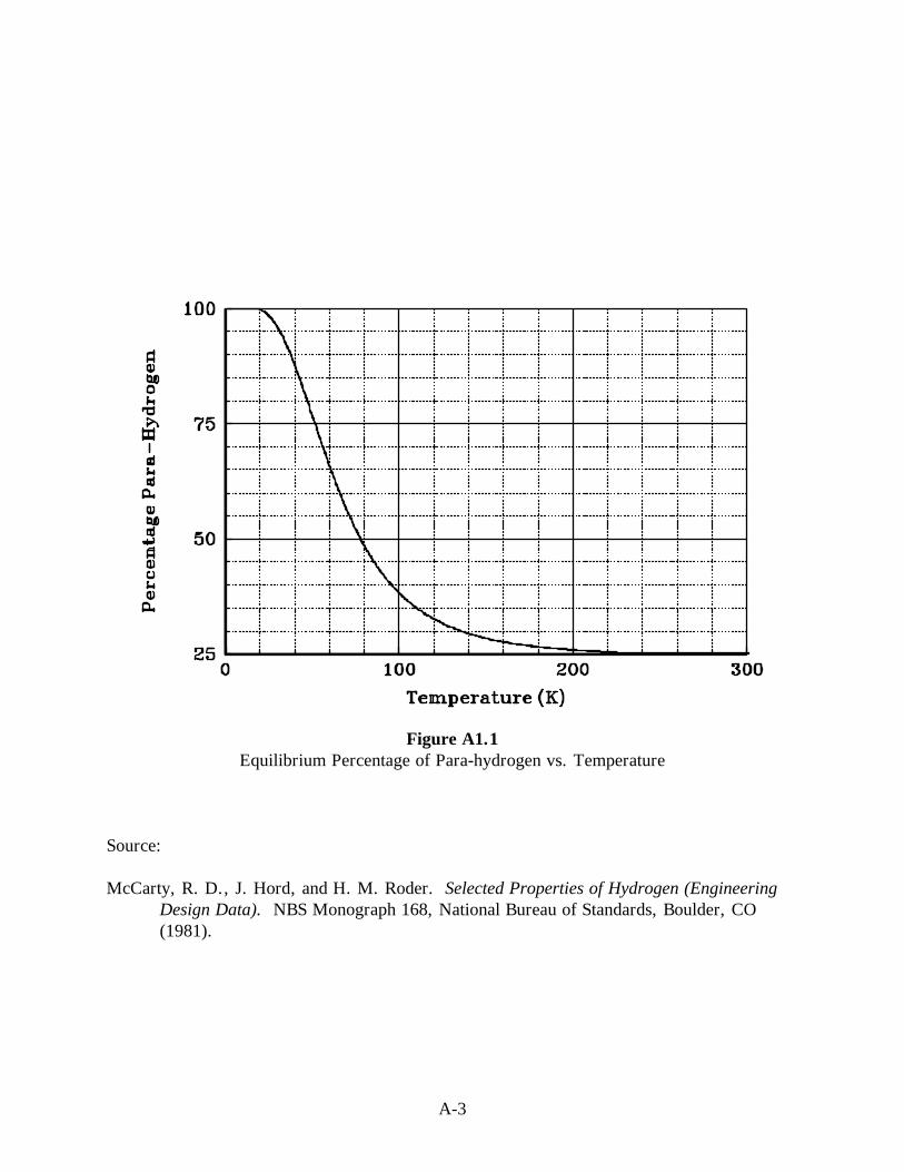
A-3
Figure A1.1Equilibrium Percentage of Para-hydrogen vs. Temperature
Source:
McCarty, R. D., J. Hord, and H. M. Roder. Selected Properties of Hydrogen (EngineeringDesign Data). NBS Monograph 168, National Bureau of Standards, Boulder, CO(1981).

A-4
Figure A1.2Enthalpy of Normal Hydrogen Conversion
Source:
McCarty, R. D., J. Hord, and H. M. Roder. Selected Properties of Hydrogen (EngineeringDesign Data). NBS Monograph 168, National Bureau of Standards, Boulder, CO(1981).

A-5
Figure A1.3Vapor Pressure of Liquefied Para-hydrogen (TP1 to NBP2)
Source:
McCarty, R. D., J. Hord, and H. M. Roder. Selected Properties of Hydrogen (EngineeringDesign Data). NBS Monograph 168, National Bureau of Standards, Boulder, CO(1981).
1 TP = Triple Point2 NBP = Normal Boling Point

A-6
Figure A1.4Vapor Pressure of LH2 (NBP1 to CP2)
Source:
McCarty, R. D., J. Hord, and H. M. Roder. Selected Properties of Hydrogen (EngineeringDesign Data). NBS Monograph 168, National Bureau of Standards, Boulder, CO(1981).
1 NBP = Normal Boiling Point2 CP = Critical Point

A-7
Figure A1.5Vapor Pressures of Normal and Para-hydrogen Below the Triple Point
Source:
McCarty, R. D., J. Hord, and H. M. Roder. Selected Properties of Hydrogen (EngineeringDesign Data). NBS Monograph 168, National Bureau of Standards, Boulder, CO(1981).

A-8
Figure A1.6Comparison of Densities and Bulk Fluid Heat Capacities forSlush, Triple-Point Liquid, and NBP1 Liquid Para-hydrogen
Source:
McCarty, R. D., J. Hord, and H. M. Roder. Selected Properties of Hydrogen (EngineeringDesign Data). NBS Monograph 168, National Bureau of Standards, Boulder, CO(1981).
1 NBP = Normal Boiling Point

A-9
Figure A1.7Proposed Phase Diagram (P-T Plane) for Solid Hydrogen
at Various Ortho-hydrogen Mole Fractions, x.
Note: Alternate branches are shown for hcp-fcc transition. Heavy solid line is melting curve.hcp=hexagonal close packed. fcc=face centered cubic.
Source:
McCarty, R. D., J. Hord, and H. M. Roder. Selected Properties of Hydrogen (EngineeringDesign Data). NBS Monograph 168, National Bureau of Standards, Boulder, CO(1981).

A-10
Figure A1.8Proposed Phase Diagram (V-T Plane) for Solid Normal Hydrogen
Note: Dashed lines indicate alternate branches for hcp-fcc transition curve. x=mole fraction.hcp=hexagonal close packed. fcc=face centered cubic.
Source:
McCarty, R. D., J. Hord, and H. M. Roder. Selected Properties of Hydrogen (EngineeringDesign Data). NBS Monograph 168, National Bureau of Standards, Boulder, CO(1981).

A-11
Figure A1.9Specific Heat (Heat Capacity) of Saturated Solid Hydrogen
Source:
McCarty, R. D., J. Hord, and H. M. Roder. Selected Properties of Hydrogen (EngineeringDesign Data). NBS Monograph 168, National Bureau of Standards, Boulder, CO(1981).

A-12
Figure A1.10Melting Line from Triple Point to Critical Point Pressure for Para-hydrogen
Source:
McCarty, R. D., J. Hord, and H. M. Roder. Selected Properties of Hydrogen (EngineeringDesign Data). NBS Monograph 168, National Bureau of Standards, Boulder, CO(1981).

A-13
Table A1.1Selected Thermophysical, Chemical, and Combustion Properties of
Gaseous, Liquefied, Slush, and Solid Para-hydrogena
Molecular Weight 2.01594
NORMAL TEMPERATURE AND PRESSURE (NTP)b
Density of GH2 83.764 g/m3 0.00523 lbm/ft3
Density of air (for comparison) 1,198 g/m3 0.0749 lbm/ft3
Specific heat at constant pressure, Cp 14.89 kJ/kg·K 3.559 Btu/lbm·°RSpecific heat ratio, γ = Cp/Cv 1.383Enthalpy 4097.7 kJ/kg 1762.8 Btu/lbm
Internal Energy 2888.0 kJ/kg 1242.5 Btu/lbm
Entropy 64.44 kJ/kg·K 15.40 Btu/lbm·°RVelocity of sound (adiabatic) 1294 m/s 4246 ft/sViscosity 8.81 µPa·s 0.00881 centipoiseThermal conductivity, k 19.14 µW/m·K 0.111 Btu/ft·h·°RDielectric constant, ε 1.00026Compressibility factor, Z 1.0006Index of refraction 1.00012
CRITICAL POINT
Temperature 32.976 K -400.6 °FPressure 1,292.8 kPa abs 187.5 psiaDensity 31.43 kg/m3 1.96 lbm/ft3
Specific heat at saturation, Cσ (very large)Specific heat at constant pressure, Cp (very large)Specific heat ratio, γ = Cp/Cv (large)Enthalpy 38.49 kJ/kg 16.56 Btu/lbm
Internal Energy 2.83 kJ/kg 1.22 Btu/lbm
Entropy 17.6 kJ/kg·K 4.20 Btu/lbm·°RVelocity of sound 350 m/s 1148 ft/sViscosity 3.5 µPa·s 0.0035 centipoiseThermal conductivity, k (anomolously large)Dielectric constant, ε 1.098Compressibility factor, Z 0.3025
NORMAL BOILING POINT (NBP)
Normal Boiling Temperature (NBT) 20.268 K -423.2 °FPressure 101.3 kPa 14.696 psiaDensity of vapor 1.338 kg/m3 0.0835 lbm/ft3
of liquid 70.78 kg/m3 4.42 lbm/ft3
Heat of vaporization 445.6 kJ/kg 191.7 Btu/lbm
Specific heat at saturation, Cσ of vapor -16.51 kJ/kg·K -3.95 Btu/lbm·°R of liquid 9.38 kJ/kg·K 2.24 Btu/lbm·°R

A-14
Table A1.1 (continued)Selected Thermophysical, Chemical, and Combustion Properties of
Gaseous, Liquefied, Slush, and Solid Para-hydrogena
Specific heat at constant pressure, Cp of vapor 12.15kJ/kg·K 2.904 Btu/lbm·°R of liquid 9.688 kJ/kg·K 2.315 Btu/lbm·°RSpecific heat ratio, γ = Cp/Cv
of vapor 1.869 of liquid 1.688Enthalpy of vapor 189.3 kJ/kg 81.5 Btu/lbm
of liquid -256.3 kJ/kg -110.2 Btu/lbm
Internal energy of vapor 113.6 kJ/kg 48.87 Btu/lbm
of liquid -257.7 kJ/kg -110.9 Btu/lbm
Entropy of vapor 29.97 kJ/kg·K 7.162 Btu/lbm·°R of liquid 7.976 kJ/kg·K 1.906 Btu/lbm·°RVelocity of sound (adiabatic) of vapor 355 m/s 1165 ft/s of liquid 1093 m/s 3586 ft/sViscosity of vapor 1.1 µPa·s 0.0011 centipoise of liquid 13.2 µPa·s 0.0132 centipoiseThermal conductivity, k of vapor 1.69 µW/m·K 0.00977 Btu/ft·h·°R of liquid 9.9 µW/m·K 0.0572 Btu/ft·h·°RDielectric constant, ε of vapor 1.0040 of liquid 1.230Compressibility factor, Z of vapor 0.9061 of liquid 0.01712Surface tension of liquid 0.00193 N/m 1.1x10⁻⁵ lbf/inIndex of refraction of liquid 1.110
TRIPLE POINT
Temperature 13.803 K -434.8 °FPressure 7.04 kPa abs 1.02 psiaDensity of vapor 0.1258 kg/m3 0.00784 lbm/ft3
of liquid 77.03 kg/m3 4.81 lbm/ft3
of solid 86.50 kg/m3 5.40 lbm/ft3
Heat of fusion 58.29 kJ/kg 25.08 Btu/lbm
Heat of vaporization 449.17 kJ/kg 193.2Btu/lbm
Heat of sublimation 507.39 kJ/kg 218.3 Btu/lbm

A-15
Table A1.1 (continued)Selected Thermophysical, Chemical, and Combustion Properties of
Gaseous, Liquefied, Slush, and Solid Para-hydrogena
Specific heat at saturation, Cσ of vapor -23.28 kJ/kg·K -5.57 Btu/lbm·°R of liquid 6.87 kJ/kg·K 1.64 Btu/lbm·°R of solid 2.84 kJ/kg·K 0.679 Btu/lbm·°RSpecific heat at constant pressure, Cp of vapor 10.52 kJ/kg·K 2.513 Btu/lbm·°R of liquid 6.513 kJ/kg·K 1.557 Btu/lbm·°RSpecific heat ratio, γ = Cp/Cv
of vapor 1.693 of liquid 1.382Enthalpy of vapor 140.3 kJ/kg 60.4 Btu/lbm
of liquid -308.9 kJ/kg -132.9 Btu/lbm
of solid -367.2 kJ/kg -158.0 Btu/lbm
Internal energy of vapor 84.23 kJ/kg 36.24 Btu/lbm
of liquid -309.0 kJ/kg -132.9 Btu/lbm
of solid -367.3 kJ/kg -158.0 Btu/lbm
Entropy of vapor 37.52 kJ/kg·K 8.967 Btu/lbm·°R of liquid 20.16 kJ/kg·K 1.186 Btu/lbm·°R of solid 0.739 kJ/kg·K 0.177 Btu/lbm·°RVelocity of sound of vapor 305 m/s 1001 ft/s of liquid 1273 m/s 4177 ft/sViscosity of vapor 0.74 µPa·s 0.00074 centipoise of liquid 26.0 µPa·s 0.026 centipoiseThermal conductivity, k of vapor 1.24 µW/m·K 0.00717 Btu/ft·h·°R of liquid 7.3 µW/m·K 0.0422 Btu/ft·h°R of solid 90 µW/m·K 0.52 Btu/ft·h·°RDielectric constant, ε of vapor 1.00038 of liquid 1.252 of solid 1.286Compressibility factor, Z of vapor 0.9850 of liquid 0.001606
Density of slush (50% by mass solid) 81.50 kg/m3 5.09 lbm/ft3
Density of slush (50% by volume solid) 81.77 kg/m3 5.11 lbm/ft3

A-16
Table A1.1 (continued)Selected Thermophysical, Chemical, and Combustion Properties of
Gaseous, Liquefied, Slush, and Solid Para-hydrogen
Gaseous, Liquefied, Slush, and Solid Para-hydrogenaTHER PROPERTIES
Equivalent vol solid @ TP/vol liquid @ NBT 0.8181Equivalent vol gas @ NTP/vol liquid @ NBT 845.1Pressure required to maintain NBP liquid density in NTP GH2 (fixed volume, no venting) 172 MPa 25,000 psiJoule-Thomson inversion temperature 193 K -112 °FHeat of combustion (low) 119.93 kJ/g 51,573 Btu/lbm
Heat of combustion (high) 141.86 kJ/g 61,003 Btu/lbm
Limits of flammability in NTP air 4.0 to 75.0 vol %Limits of flammability in NTP oxygen 4.1 to 94.0 vol %Limits of detonability in NTP air 18.3 to 59.0 vol %Limits of detonability in NTP oxygen 15 to 90 vol %Stoichiometric composition in air 29.53 vol %Minimum energy for ignition in air 0.017 mJ 1.6x10⁻⁸ BtuAutoignition temperature 858 K 1085 °FHot air-jet ignition temperature 943 K 1238 °FFlame temperature in air 2318 K 3713 °FThermal energy radiated from flame to surroundings 17 to 25%Burning velocity in NTP air 265 to 325 cm/s 104 to 128 in/sDetonation velocity in NTP air 1.48 to 2.15 km/s 4856 to 7054 ft/sDiffusion coefficient in NTP air 0.61 cm2/s 0.095 in2/sDiffusion velocity in NTP air <2.0 cm/s 0.79 in/sBuoyant velocity in NTP air 1.2 to 9 m/s 3.9 to 30 ft/sMaximum experimental safe gap in NTP air 0.008 cm 0.003 in.Quenching gap in NTP air 0.064 cm 0.025 in.Detonation induction distance in NTP air L/D≈100Limiting oxygen index 5.0 vol %Vaporization rates (steady state) of liquid pools without burning 2.5 to 5.0 cm/s 1 to 2 in/sBurning rates of spilled liquid pools 0.5 to 1.1 mm/s 0.02 to 0.04 in/sEnergy of explosion (theoretical explosive yield)
≈24 (g TNT)/(g H2) ≈24 (lbm TNT)/(lbm H2)0.17 (g TNT)/(kJ H2) 4.0x10⁻⁴ (lbm TNT)/(Btu H2)2.02 (kg TNT)/m3 NTP GH2) 0.126 lbm TNT)/(ft3 NTP GH2)1.71 (g TNT)/(cm3 NBP LH2) 107.3(lbm TNT)/(ft3 NBP LH2)
a McCarty, R. D., J. Hord, and H. M. Roder, Selected Properties of Hydrogen (Engineering Design Data), NBS Monograph 168,National Bureau of Standards, Boulder, CO (1981).
b NTP =293 K (68 °F) and 101.3 kPa (14.69 psia)
NOTE: Temperature dependent ortho-para changes continue to influence properties in the solid state. Several properties (such asspecific heat, thermal conductivity, and thermal diffusivity) are highly sensitive to actual ortho-para composition.

Table A1.2Fixed Point Properties of Normal Hydrogenb
Triple Point Normal Boiling PointProperties Solid Liquid Vapor Liquid Vapor Critical Point STP NTP
Temperature a, -434.55 -434.55 -434.55 -422.97 -422.97 -399.93 32.000 68.000 °F (K) (13.957) (13.957) (13.957) (20.390) (20.390) (33.190) (273.15) (293.15)
Pressure (inches Hg) 2.147 2.147 2.147 30.19 30.19 391.9 30.19 30.19 (mm Hg) (54.04) (54.04) (54.04) (760.0) (760.0) (9865) (760.0) (760.0)
Density, lb/ft3 5.409 4.817 8.099x10⁻³ 4.427 83.05x10⁻³ 1.879 5.609x10⁻³ 5.225x10⁻³
(mol/cm3) (0.04301) (0.03830) (0.0644x10⁻³) (0.0352) (0.6604x10⁻³) (0.01494) (0.0446x10⁻³) (0.04155x10⁻³)
Specific volume, ft3/lb 0.1849 0.2076 123.5 0.2259 12.05 0.5322 178.3 191.38 (cm3/mol) (23.25) (26.11) (15.530) (28.41) (1514) (66.93) (22.420) (24.070)
Compressibility factor, ---- 0.001621 0.9635 0.01698 0.9051 0.3191 1.00042 1.00049 Z = PV/RT
Heats of fusion and 24.99 194.4 ---- 191.9 ---- 0 (0) ---- ---- vaporization, (117.1) (911.3) ---- (899.1) ---- ---- ---- Btu/lb (J/mol)
Specific heat, Btu/lb·°R (J/g·K) At saturation, Cσ 0.6794 1.642 -5.565 2.242 -3.946 very large ---- ----
(2.842) (6.870) (-23.28) (9.380) (-16.51) ---- ----
At constant pressure, ---- 1.569 2.516 2.336 2.917 very large 3.390 3.425 Cp ---- (6.563) (10.526) (9.772) (12.20) (14.18) (14.33)
At constant volume, Cv ---- 1.130 1.484 1.375 1.565 2.336 2.407 2.419(4.727) (6.211) (5.754) (6.548) (9.772) (10.07) (10.12)
Specific heat ratio, γ= Cp/Cv ---- 1.388 1.695 1.698 1.863 large 1.408 1.416

Table A1.2 (continued)Fixed Point Properties of Normal Hydrogen
Triple Point Normal Boiling PointProperties Solid Liquid Vapor Liquid Vapor Critical Point STP NTP
Enthalpy 68.63 93.62 288.1 117.0 308.9 248.4 1654 1776 Btu/lb (J/mol) (321.6) (438.7) (1350) (548.3) (1447) (1164) (7749) (8324)
Internal energy, 67.84 92.83 263.5 116.5 276.2 ---- 1169 1256 Btu/lb (J/mol) (317.9) (435.0) (1235) (545.7) (1294) ---- (5477) (5885)
Entropy, Btu/hr·°R 2.41 3.40 11.1 4.14 9.36 6.47 16.5 16.8
(J/mol K) (20.3) (28.7) (93.6) (34.92) (78.94) (54.57) (139.6) (141.6)
Velocity of sound, ---- 4206 1007 3612 1171 ---- 4088 4246 ft/s (m/s) ---- (1282) (307) (1101) (357) ---- (1246) (1294)
Viscosity, centipoise (µPa·s) ---- 0.026 0.00074 0.0132 0.0011 0.0035 0.00839 0.00881
---- (26) (0.74) (13.2) (1.1) (3.5) (8.39) (8.81)
Thermal conductivity, k 0.52 0.042 0.0072 0.057 0.0098 anomolously 0.098 0.106Btu/ft·h·°R (µW/m·K) (90) (7.3) (1.24) (9.9) (1.69) large (17.40) (18.38)
Prandtl no. ---- 2.34 0.630 1.30 0.798 ---- 0.682 0.688Dielectric constant, ε 1.287 1.253 1.00039 1.231 1.0040 1.0937 1.000271 1.000253Index of refraction 1.134 1.119 1.000196 1.1093 1.0020 1.0458 1.000136 1.000126
Surface tension, ---- 0.0171x10-
3---- 0.0111x10⁻³ ---- 0 (0) ---- ----
lbf/in (N/m) ---- (3.00x10⁻³) ---- (1.94x10⁻³) ---- ---- ----Equivalent volume per volume of liquid at NBT 0.8184 0.9190 546.3 1.000 53.30 2.357 789.3 847.1a These temperatures are based on the IPTS-1968 temperature scale.b McCarty, R. D., J. Hord, and H. M. Roder, Selected Properties of Hydrogen (Engineering Design Data), NBS Monograph 168, National Bureau of Standards, Boulder, Colorado, (1981).NOTE: Dashes indicate not applicable.

Table A1.3Thermodynamic Properties of the Hydrogen Solid-Vapor Two Phase Regiona
Pressure Temp V-SOL D-SOL H-SOL S-SOL U-SOL C-SAT C-P ∆HSUB V-VAP D-VAP H-VAP S-VAP U-VAP(ATM) (K) (CC/MOL) (MOL/L) (J/MOL) (J/MOL-K) (J/MOL) (J/MOL-K) (J/MOL-K) (J/MOL) (CC/MOL) (MOL/L) (J/MOL) (J/MOL-K) (J/MOL)
.06950 13.8 23.30 42.911 -740.2 1.500 -740.4 5.634 5.640 1022.1 16010. .06238 281.9 75.57 169.0
.06505 13.7 23.29 42.931 -740.8 1.459 -740.9 5.502 5.508 1021.0 17015. .05877 280.2 75.98 168.1
.06084 13.6 23.28 42.950 -741.3 1.420 -741.5 5.371 5.377 1019.8 18074. .05533 278.5 76.40 167.0
.05685 13.5 23.27 42.969 -741.8 1.380 -742.0 5.243 5.248 1018.5 19213. .05205 276.7 76.83 l66.0
.05308 13.4 23.26 42.989 -742.4 1.342 -742.5 5.117 5.122 1017.3 20441. .04892 274.9 77.26 165.0
.04951 13.3 23.25 43.007 -742.9 1.304 -743.0 4.992 4.997 1016.0 21765. .04594 273.1 77.69 163.9
.04614 13.2 23.24 43.026 -743.4 1.267 -743.5 4.870 4.874 1014.6 23194. .04311 271.3 78.13 162.9
.04296 13.l 23.23 43.045 -743.8 1.230 -743.9 4.750 4.754 1013.3 24738. .04042 269.5 78.58 161.8
.03996 13.0 23.22 43.063 -744.3 1.194 -744.4 4.631 4.635 1011.9 26407. .03787 267.6 79.03 l60.7
.03713 12.9 23.21 43.082 -744.8 1.159 -744.8 4.514 4.518 1010.5 28215. .03544 265.7 79.49 159.6
.03447 12.8 23.20 43.100 -745.2 1.124 -745.3 4.400 4.403 1009.0 30173. .03314 263.8 79.96 158.4
.03197 12.7 23.19 43.118 -745.6 1.090 -745.7 4.287 4.290 1007.6 32298. .03096 261.9 80.43 157.3
.02962 12.6 23.18 43.135 -746.l 1.057 -746.1 4.176 4.179 1006.1 34606. .02890 260.0 80.90 156.2
.02741 12.5 23.17 43.153 -746.5 1.024 -746.5 4.067 4.070 1004.5 37114. .02694 258.1 81.39 155.0
.02534 12.4 23.16 43.170 -746.9 0.992 -746.9 3.960 3.963 1003.0 39845. .02510 256.1 81.88 153.8
.02340 12.3 23.15 43.188 -747.3 0.960 -747.3 3.855 3.858 1001.4 42821. .02335 254.2 82.38 152.6
.02158 12.2 23.15 43.205 -747.6 0.929 -747.7 3.751 3.753 999.8 46067. .02171 252.2 82.88 151.5
.01988 12.1 23.14 43.222 -748.0 0.899 -748.1 3.650 3.652 998.2 49613. .02016 250.2 83.40 150.3
.01830 12.0 23.13 43.238 -748.4 0.869 -748.4 3.550 3.552 996.6 53491. .01869 248.2 83.92 149.0
.01681 11.9 23.12 43.255 -748.7 0.839 -748.8 3.452 3.454 994.9 57738. .01732 246.2 84.45 147.8
.01543 11.8 23.11 43.271 -749.1 0.811 -749.1 3.356 3.358 993.2 62395- .01603 244.2 84.98 146.6
.01415 11.r 23.10 43.287 -749.4 0.783 -749.4 3.261 3.263 991.5 67509. .01481 242.1 85.53 145.4
.01295 11.6 23.09 43.303 -749.7 0.755 -749.8 3.169 3.170 989.8 73131. .01367 240.1 86.09 144.1
.01184 11.5 23.08 43.319 -750.0 0.728 -750.1 3.078 3.079 988.1 79321. .01261 238.1 86.65 142.9
.01081 11.4 23.08 43.335 -750.3 0.701 -750.4 2.989 2.990 986.3 86146. .01161 236.0 87.22 141.6
.00986 11.3 23.07 43.350 -750.6 0.676 -750.7 2.901 2.902 984.6 93682. .01067 233.9 87.81 140.4
.00898 11.2 23.06 43.366 -750.9 0.650 -750.9 2.815 2.816 982.8 102017. .00980 231.9 88.40 139.1
.00816 11.1 23.05 43.381 -751.2 0.625 -751.2 2.731 2.732 981.0 111248. .00899 229.8 89.00 137.8
.00741 11.0 23.04 43.396 -751.5 0.601 -751.5 2.649 2.650 979.2 121489. .00823 227.7 89.62 136.5
.00671 10.9 23.04 43.411 -751.7 0.577 -751.7 2.568 2.569 977.3 132869. .00753 225.6 90.24 135.3
.00607 10.8 23.03 43.425 -752.0 0.554 -752.0 2.489 2.490 975.5 145535. .00687 223.5 90.88 134.0
.00549 10.7 23.02 43.440 -752.2 0.531 -752.2 2.412 2.412 973.6 159656. .00626 221.4 91.52 132.7
.00495 10.6 23.01 43.454 -752.5 0.509 -752.5 2.336 2.336 971.8 175429. .00570 219.3 92.18 131.4
.00445 10.5 23.01 43.468 -752.7 0.487 -752.7 2.262 2.262 969.9 193077. .00518 217.2 92.86 130.1
.00400 10.4 23.00 43.482 -752.9 0.466 -752.9 2.109 2.189 968.0 212861. .00470 215.l 93.54 128.8
.00359 10.3 22.99 43.496 -753.l 0.445 -753.1 2.118 2.118 966.l 235082. .00425 213.0 94.24 127.5
.00321 10.2 22.98 43.509 -753.3 0.424 -753.3 2.048 2.048 964.2 260087. .00384 210.8 94.95 126.2
.00287 10.1 22.98 43.523 -753.5 0.405 -753.5 1.980 1.980 962.2 288284. .00347 208.7 95.68 124.9
.00256 10.0 22.97 43.536 -753.7 0.385 -753.7 1.914 1.914 960.3 320146. .00312 206.6 96.42 123.5
(MM HG) (K) (CC/MOL) (CAL/MOL) (CAL/MOL-K) (CAL/MOL-K) (CAL/MOL) (Z, VAPOR) (CAL/MOL) (CAL/MOL-K)
.1917E+0l 10.0 22.873 1.4790000 .1975000 .5751000 230.55 .99878 232.03 23.252
.5343E+00 9.0 22.809 .9788000 .1450000 .4280000 226.12 .99956 227.10 25.269
.1118E+00 8.0 22.754 .6139000 .1022000 .3054000 221.53 1.00000 222.15 27.794
.1561E-01 7.0 22.711 .3598000 .0684200 .2065000 216.82 1.00000 217.18 31.043
.1198E-02 6.0 22.678 .1933000 .0429100 .1301000 212.02 1.00000 212.21 35.379
.3570E-04 5.0 22.660 .0927500 .0247300 .0742000 207.15 1.00000 207.24 41.455
.2080E-06 4.0 22.650 .0379900 .0126600 .0379900 202.24 1.00000 202.28 50.572
.4832E-10 3.0 22.646 .0120200 .0053420 .0160300 197.30 1.00000 197.31 65.771
.3985E-17 2.0 22.645 .0023740 .0015830 .0047490 192.34 1.00000 192.34 96.170
.8255E-38 1.0 22.645 .0001484 .0001979 .0005936 187.37 1.00000 187.37 187.372
a McCarty, R. D., J. Hord, and H. M. Roder, Selected Properties of Hydrogen (Engineering Design Data), NBS Monograph 168, National Bureau of Standards, Boulder, CO (1981).
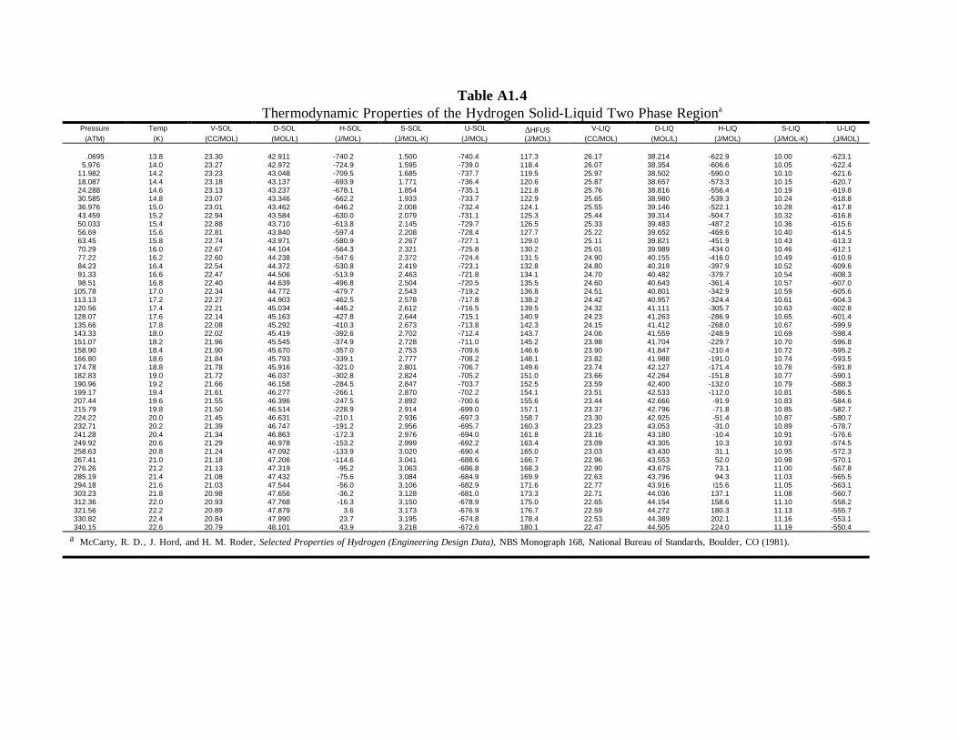
Table A1.4Thermodynamic Properties of the Hydrogen Solid-Liquid Two Phase Regiona
Pressure Temp V-SOL D-SOL H-SOL S-SOL U-SOL ∆HFUS V-LIQ D-LIQ H-LIQ S-LIQ U-LIQ
(ATM) (K) (CC/MOL) (MOL/L) (J/MOL) (J/MOL-K) (J/MOL) (J/MOL) (CC/MOL) (MOL/L) (J/MOL) (J/MOL-K) (J/MOL)
.0695 13.8 23.30 42.911 -740.2 1.500 -740.4 117.3 26.17 38.214 -622.9 10.00 -623.15.976 14.0 23.27 42.972 -724.9 1.595 -739.0 118.4 26.07 38.354 -606.6 10.05 -622.4
11.982 14.2 23.23 43.048 -709.5 1.685 -737.7 119.5 25.97 38.502 -590.0 10.10 -621.618.087 14.4 23.18 43.137 -693.9 1.771 -736.4 120.6 25.87 38.657 -573.3 10.15 -620.724.288 14.6 23.13 43.237 -678.1 1.854 -735.1 121.8 25.76 38.816 -556.4 10.19 -619.830.585 14.8 23.07 43.346 -662.2 1.933 -733.7 122.9 25.65 38.980 -539.3 10.24 -618.836.976 15.0 23.01 43.462 -646.2 2.008 -732.4 124.1 25.55 39.146 -522.1 10.28 -617.843.459 15.2 22.94 43.584 -630.0 2.079 -731.1 125.3 25.44 39.314 -504.7 10.32 -616.850.033 15.4 22.88 43.710 -613.8 2.145 -729.7 126.5 25.33 39.483 -487.2 10.36 -615.656.69 15.6 22.81 43.840 -597.4 2.208 -728.4 127.7 25.22 39.652 -469.6 10.40 -614.563.45 15.8 22.74 43.971 -580.9 2.267 -727.1 129.0 25.11 39.821 -451.9 10.43 -613.370.29 16.0 22.67 44.104 -564.3 2.321 -725.8 130.2 25.01 39.989 -434.0 10.46 -612.177.22 16.2 22.60 44.238 -547.6 2.372 -724.4 131.5 24.90 40.155 -416.0 10.49 -610.984.23 16.4 22.54 44.372 -530.8 2.419 -723.1 132.8 24.80 40.319 -397.9 10.52 -609.691.33 16.6 22.47 44.506 -513.9 2.463 -721.8 134.1 24.70 40.482 -379.7 10.54 -608.398.51 16.8 22.40 44.639 -496.8 2.504 -720.5 135.5 24.60 40.643 -361.4 10.57 -607.0
105.78 17.0 22.34 44.772 -479.7 2.543 -719.2 136.8 24.51 40.801 -342.9 10.59 -605.6113.13 17.2 22.27 44.903 -462.5 2.578 -717.8 138.2 24.42 40.957 -324.4 10.61 -604.3120.56 17.4 22.21 45.034 -445.2 2.612 -716.5 139.5 24.32 41.111 -305.7 10.63 -602.8128.07 17.6 22.14 45.163 -427.8 2.644 -715.1 140.9 24.23 41.263 -286.9 10.65 -601.4135.66 17.8 22.08 45.292 -410.3 2.673 -713.8 142.3 24.15 41.412 -268.0 10.67 -599.9143.33 18.0 22.02 45.419 -392.6 2.702 -712.4 143.7 24.06 41.559 -248.9 10.69 -598.4151.07 18.2 21.96 45.545 -374.9 2.728 -711.0 145.2 23.98 41.704 -229.7 10.70 -596.8158.90 18.4 21.90 45.670 -357.0 2.753 -709.6 146.6 23.90 41.847 -210.4 10.72 -595.2166.80 18.6 21.84 45.793 -339.1 2.777 -708.2 148.1 23.82 41.988 -191.0 10.74 -593.5174.78 18.8 21.78 45.916 -321.0 2.801 -706.7 149.6 23.74 42.127 -171.4 10.76 -591.8182.83 19.0 21.72 46.037 -302.8 2.824 -705.2 151.0 23.66 42.264 -151.8 10.77 -590.1190.96 19.2 21.66 46.158 -284.5 2.847 -703.7 152.5 23.59 42.400 -132.0 10.79 -588.3199.17 19.4 21.61 46.277 -266.1 2.870 -702.2 154.1 23.51 42.533 -112.0 10.81 -586.5207.44 19.6 21.55 46.396 -247.5 2.892 -700.6 155.6 23.44 42.666 -91.9 10.83 -584.6215.79 19.8 21.50 46.514 -228.9 2.914 -699.0 157.1 23.37 42.796 -71.8 10.85 -582.7224.22 20.0 21.45 46.631 -210.1 2.936 -697.3 158.7 23.30 42.925 -51.4 10.87 -580.7232.71 20.2 21.39 46.747 -191.2 2.956 -695.7 160.3 23.23 43.053 -31.0 10.89 -578.7241.28 20.4 21.34 46.863 -172.3 2.976 -694.0 161.8 23.16 43.180 -10.4 10.91 -576.6249.92 20.6 21.29 46.978 -153.2 2.999 -692.2 163.4 23.09 43.305 10.3 10.93 -574.5258.63 20.8 21.24 47.092 -133.9 3.020 -690.4 165.0 23.03 43.430 31.1 10.95 -572.3267.41 21.0 21.18 47.206 -114.6 3.041 -688.6 166.7 22.96 43.553 52.0 10.98 -570.1276.26 21.2 21.13 47.319 -95.2 3.063 -686.8 168.3 22.90 43.67S 73.1 11.00 -567.8285.19 21.4 21.08 47.432 -75.6 3.084 -684.9 169.9 22.63 43.796 94.3 11.03 -565.5294.18 21.6 21.03 47.544 -56.0 3.106 -682.9 171.6 22.77 43.916 l15.6 11.05 -563.1303.23 21.8 20.98 47.656 -36.2 3.128 -681.0 173.3 22.71 44.036 137.1 11.08 -560.7312.36 22.0 20.93 47.768 -16.3 3.150 -678.9 175.0 22.65 44.154 158.6 11.10 -558.2321.56 22.2 20.89 47.879 3.6 3.173 -676.9 176.7 22.59 44.272 180.3 11.13 -555.7330.82 22.4 20.84 47.990 23.7 3.195 -674.8 178.4 22.53 44.389 202.1 11.16 -553.1340.15 22.6 20.79 48.101 43.9 3.218 -672.6 180.1 22.47 44.505 224.0 11.19 -550.4
a McCarty, R. D., J. Hord, and H. M. Roder, Selected Properties of Hydrogen (Engineering Design Data), NBS Monograph 168, National Bureau of Standards, Boulder, CO (1981).

A-21
Table A1.5Molar Volumea of Compressed Solid Para-hydrogenb
Temperature(K)
Pressure(atm)
11.49 13.98 16.89 18.20 19.97
0 23.0825 22.63 22.8350 22.22 22.5875 21.85 22.24
100 21.53 21.93150 21.26 22.00200 21.55 21.52250 21.10 21.07 21.45
300 20.70 21.30350 21.15
a All values of the molar volume are in cubic centimeters per mole.b McCarty, R. D., J. Hord, and H. M. Roder. Selected Properties of Hydrogen (Engineering
Design Data). NBS Monograph 168, National Bureau of Standards, Boulder, CO (1981).

A-22
Table A1.6Thermal Expansion of Solid Para-hydrogena
Temperature(K)
Thermal Expansioncoefficient, α x 104
(1/K)
Temperature(K)
Thermal Expansioncoefficient, α x 104
(1/K)1 0.022 8 21.72 0.22 9 26.73 1.0 10 30.44 3.0 11 34.65 6.5 12 39.46 11.3 13 44.77 16.5 13.80 49.4
a McCarty, R. D., J. Hord, and H. M. Roder. Selected Properties of Hydrogen (EngineeringDesign Data). NBS Monograph 168, National Bureau of Standards, Boulder, CO (1981).

ADDENDUM: SAMPLE MATERIAL SAFETY DATA SHEETSFOR GASEOUS AND LIQUEFIED HYDROGEN
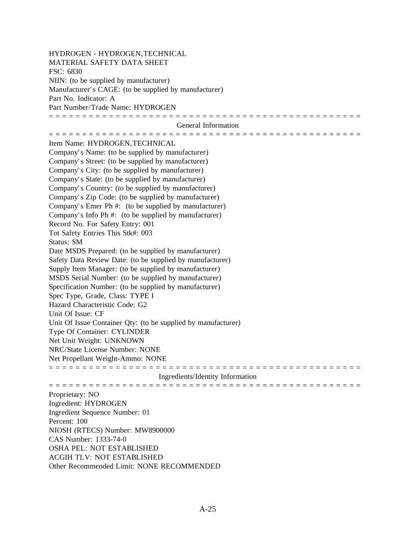
A-25
HYDROGEN - HYDROGEN,TECHNICALMATERIAL SAFETY DATA SHEETFSC: 6830NIIN: (to be supplied by manufacturer)Manufacturer's CAGE: (to be supplied by manufacturer)Part No. Indicator: APart Number/Trade Name: HYDROGEN===============================================
General Information===============================================Item Name: HYDROGEN,TECHNICALCompany's Name: (to be supplied by manufacturer)Company's Street: (to be supplied by manufacturer)Company's City: (to be supplied by manufacturer)Company's State: (to be supplied by manufacturer)Company's Country: (to be supplied by manufacturer)Company's Zip Code: (to be supplied by manufacturer)Company's Emer Ph #: (to be supplied by manufacturer)Company's Info Ph #: (to be supplied by manufacturer)Record No. For Safety Entry: 001Tot Safety Entries This Stk#: 003Status: SMDate MSDS Prepared: (to be supplied by manufacturer)Safety Data Review Date: (to be supplied by manufacturer)Supply Item Manager: (to be supplied by manufacturer)MSDS Serial Number: (to be supplied by manufacturer)Specification Number: (to be supplied by manufacturer)Spec Type, Grade, Class: TYPE IHazard Characteristic Code: G2Unit Of Issue: CFUnit Of Issue Container Qty: (to be supplied by manufacturer)Type Of Container: CYLINDERNet Unit Weight: UNKNOWNNRC/State License Number: NONENet Propellant Weight-Ammo: NONE===============================================
Ingredients/Identity Information===============================================Proprietary: NOIngredient: HYDROGENIngredient Sequence Number: 01Percent: 100NIOSH (RTECS) Number: MW8900000CAS Number: 1333-74-0OSHA PEL: NOT ESTABLISHEDACGIH TLV: NOT ESTABLISHEDOther Recommended Limit: NONE RECOMMENDED

A-26
===============================================Physical/Chemical Characteristics
===============================================Appearance And Odor: COLORLES GAS AT NORMAL TEMPERATURE AND PRESSURE;ODORLESSBoiling Point: -422F,-252CMelting Point: -434F,-259CVapor Pressure (MM Hg/70 F): GASVapor Density (Air=1): 0.696Specific Gravity: GASDecomposition Temperature: UNKNOWNEvaporation Rate And Ref: N/ASolubility In Water: NEGLIGIBLEViscosity: UNKNOWNCorrosion Rate (IPY): UNKNOWNAutoignition Temperature: 968F===============================================
Fire and Explosion Hazard Data===============================================Flash Point: FLAMMABLE GASLower Explosive Limit: 4Upper Explosive Limit: 75Extinguishing Media: CO2, DRY CHEMICALS, WATER SPRAY OR FOGSpecial Fire Fighting Proc: EVACUATE AREA. COOL CONTAINER W/WATER SPRAY(MAX DISTANCE). DO NOT EXTINGUISH FLAMES, ALLOW TO BURN OUT! USE SCBA.STOP GAS FLOW & REMOVE CONTAINERS IF W/O RISKUnusual Fire And Expl Hazrds: FLAME NEARLY INVISIBLE. FORMS EXPOLSIVEMIXTURES W/AIR & OXIDIZERS. KEEP CONTAINERS BELOW 125F. ESCAPING GAS MAYIGNITE SPONTANEOUSLY, HAS LOW IGNITION ENERGY.===============================================
Reactivity Data===============================================Stability: YESCond To Avoid (Stability): FOLLOW COMPRESSED GAS ASSN INSTRUCTIONS INPAMPHLET "SAFE HANDLING OF COMPRESSED GAS IN CONTAINERS".Materials To Avoid: OXIDIZING AGENTS, LITHIUM, HALOGENSHazardous Decomp Products: NONEHazardous Poly Occur: NOConditions To Avoid (Poly): WILL NOT OCCUR.===============================================
Health Hazard Data===============================================LD50-LC50 Mixture: LD50 (ORAL RAT) IS UNKNOWNRoute Of Entry - Inhalation: YESRoute Of Entry - Skin: NORoute Of Entry - Ingestion: NOHealth Haz Acute And Chronic: INGESTED:UNLIKELY ROUTE OF EXPOSURE. SKIN:NOEVIDENCE OF ADVERSE EFFECTS. INHALED:SIMPLE ASPHYXIANT. MODERATECONCENTRATIONS. MAY CAUSE HEADACHE, DROWSINESS, EXCITATION, EXCESS
A-27
SALIVATION, VOMITING & UNCONSCIOUSNESS. EYE:NO EVIDENCE OF ADVERSEEFFECTS.Carcinogenicity - NTP: NOCarcinogenicity - IARC: NOCarcinogenicity - OSHA: NOExplanation Carcinogenicity: MFR LISTED NO INFORMATION ABOUT THECARCINOGENICITY OF THIS MATERIAL. HMIS DOES NOT EXPECT IT TO BECARCINOGENIC.Signs/Symptoms Of Overexp: INGESTED:UNLIKELY ROUTE OF EXPOSURE. SKIN:NOEVIDENCE OF ADVERSE EFFECTS. INHALED:SIMPLE ASPHYXIANT. HEADACHE,NO EVIDENCE OF ADVERSE EFFECTS.Med Cond Aggravated By Exp: A KNOWLEDGE OF THE AVAILABLE TOXICOLOGYINFORMATION AND OF THE PHYSICAL & CHEMICAL PROPERTIES OF THE MATERIALSUGGEST THAT OVEREXPOSURE IS UNLIKELY TO AGGRAVATE EXISTING MEDICALCONDITIONS.Emergency/First Aid Proc: INGESTED:PRODUCT IS A GAS AT NORMAL TEMPERATURE& PRESSURE. SKIN:WASH WITH SOAP & WATER. INHALED:REMOVE TO FRESH AIR.GIVE OXYGEN IF BREATHING IS DIFFICULT, ARTIFICIAL RESPIRATION IF NOTBREATHING. GET IMMEDIATE MEDICAL ATTENTION. EYE:FLUSH W/WATER. NOTE TOPHYSICIAN:THERE IS NO SPECIFIC ANTIDOTE. PRODUCT IS RELATIVELY INERT.TREATMENT SHOULD CONTROL SYMPTOMS AND CLINICAL CONDITION.===============================================
Precautions for Safe Handling and Use===============================================Steps If Matl Released/Spill: DANGER! FORMS EXPLOSIVE MIXTURES W/AIR!EVACUATE AREA. USE SCBA. REMOVE SOURCES OF IGNITION IF W/O RISK. STOP LEAKIF W/O RISK. VENTILATE AREA OR MOVE CONTAINER TO WELL-VENTILATED AREA IFW/O RISK. CHECK ATMOSPHERE FOR EXPLOSIVENESS BEFORE ENTERING.Neutralizing Agent: NO INFORMATION GIVEN BY MFR ON MSDS.Waste Disposal Method: PREVENT WASTE FROM CONTAMINATING SURROUNDINGENVIRONMENT. DISCARD ANY PRODUCT, RESIDUE, DISPOSABLE CONTAINER ORLINER IN AN ENVIRONMENTALLY ACCEPTABLE MANNER IN FULL COMPLIANCEFEDERAL, STATE & LOCAL REGULATIONS.Precautions-Handling/Storing: FOLLOW COMPRESSED GAS ASSN INSTRUCTIONS INPAMPHLET "SAFE HANDLING OF COMPRESSED GAS IN CONTAINERS". NEVER WORKON A PRESSURIZED SYSTEM.Other Precautions: PROTECT CYLINDERS FROM DIRECT SUNLIGHT & STORE IN AWELL VENTILATED AREA. PROTECT FROM PHYSICAL DAMAGE. ISOLATE CYLINDERSFROM OXYGEN & CHLORINE. DO NOT LOAD WITH EXPLOSIVES, POISONS,RADIOACTIVE MATERIALS & ORGANIC PEROXIDES.===============================================
Control Measures===============================================Respiratory Protection: NONE REQUIRED UNDER NORMAL USE. HOWEVER AIRSUPPLIED RESPIRATORS ARE REQUIRED WHILE WORKING IN CONFINED SPACES WITHTHIS PRODUCT. THE RESPIRATORY PROTECTION USE MUST CONFORM WITH OSHARULES IN 29 CFR1910.134.Ventilation: USE EXPLOSION PROOF GENERAL/LOCAL EXHAUST SUFFICIENT TOCONTROL WORKER EXPOSURE.Protective Gloves: PREFERRED FOR CYLINDER HANDLING
A-28
Eye Protection: SELECT PER OSHA 29CFR1910.133Other Protective Equipment: METATARSAL SHOES FOR CYLINDER HANDLING. SELECTPER OSHA 29CFR1910.132 & 1910.133.Work Hygienic Practices: MFR: ? HMIS:USE GOOD INDUSTRIAL HYGIENE PRACTICE.AVOID UNNECESSARY EXPOSURE. WASH THOROUGHLY BEFORE EATING ORDRINKINGSuppl. Safety & Health Data: NONE===============================================
Transportation Data===============================================Trans Data Review Date: 94365DOT PSN Code: HLRDOT Proper Shipping Name: HYDROGEN, COMPRESSEDDOT Class: 2.1DOT ID Number: UN1049DOT Label: FLAMMABLE GASIMO PSN Code: IGHIMO Proper Shipping Name: HYDROGEN, COMPRESSEDIMO Regulations Page Number: 2148IMO UN Number: 1049IMO UN Class: 2(2.1)IMO Subsidiary Risk Label: -IATA PSN Code: NSDIATA UN ID Number: 1049IATA Proper Shipping Name: HYDROGEN, COMPRESSEDIATA UN Class: 2.1IATA Label: FLAMMABLE GASAFI PSN Code: NSDAFI Symbols: 0AFI Prop. Shipping Name: HYDROGEN, COMPRESSEDAFI Class: 2.1AFI ID Number: UN1049AFI Label: FLAMMABLE GASAFI Basic Pac Ref: 6-6,6-10===============================================
Disposal Data===============================================
===============================================Label Data
===============================================Label Required: YESTechnical Review Date: 31DEC94MFR Label Number: NONELabel Status: FCommon Name: HYDROGENSignal Word: DANGER!Acute Health Hazard-Slight: XContact Hazard-Slight: XFire Hazard-Severe: X

A-29
Reactivity Hazard-None: XSpecial Hazard Precautions: **TARGET ORGANS:RESPIRATORY SYSTEM**INGESTED:UNLIKELY ROUTE OF EXPOSURE. SKIN:NO EVIDENCE OF ADVERSEEFFECTS.INHALED:SIMPLE ASPHYXIANT. MODERATE CONCENTRATIONS MAY CAUSEHEADACHE, DROWSINESS,EXCITATION,EXCESS SALVATION,VOMITING &UNCONSCIOUSNESS.EYE:NO EVIDENCE OF ADVERSE EFFECTS.FOLLOW COMPRESSED GAS ASSN INSTRUCTIONS IN DANGER! FORMS EXPLOSIVEMIXTURES W/AIR! EVACUATE AREA,USE SCBA. REMOVE SOURCES OF IGNITION &STOP LEAK IF W/O RISK. VENTILATE AREA OR MOVE CONTAINER TO WELLVENTILATED AREA IF W/O RISK. CHECK ATMOSPHERE FOR EXPLOSIVENESSENTERING AREA.Protect Eye: YProtect Skin: YLabel Name: (to be supplied by manufacturer)Label Street: (to be supplied by manufacturer)Label City: (to be supplied by manufacturer)Label State: (to be supplied by manufacturer)Label Zip Code: (to be supplied by manufacturer)Label Country: (to be supplied by manufacturer)Label Emergency Number: (to be supplied by manufacturer)==============================================
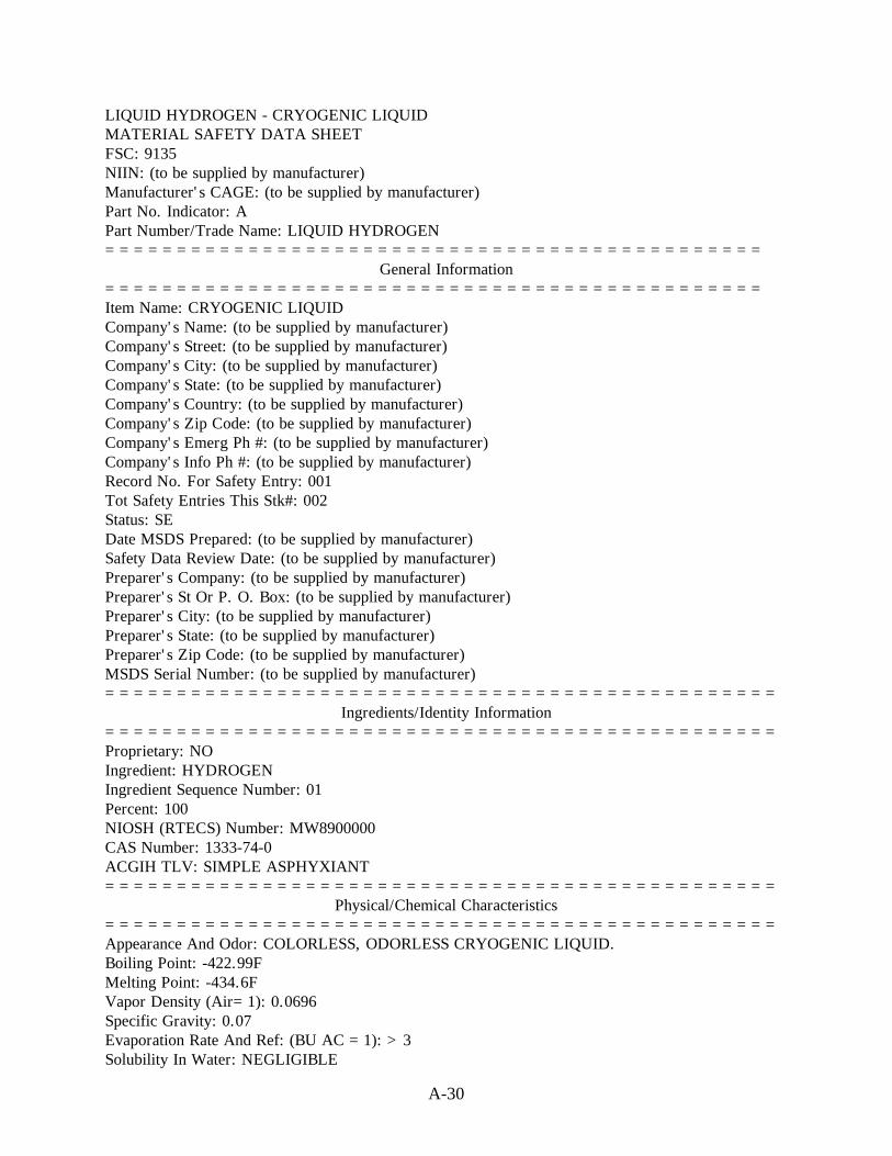
A-30
LIQUID HYDROGEN - CRYOGENIC LIQUIDMATERIAL SAFETY DATA SHEETFSC: 9135NIIN: (to be supplied by manufacturer)Manufacturer's CAGE: (to be supplied by manufacturer)Part No. Indicator: APart Number/Trade Name: LIQUID HYDROGEN==============================================
General Information==============================================Item Name: CRYOGENIC LIQUIDCompany's Name: (to be supplied by manufacturer)Company's Street: (to be supplied by manufacturer)Company's City: (to be supplied by manufacturer)Company's State: (to be supplied by manufacturer)Company's Country: (to be supplied by manufacturer)Company's Zip Code: (to be supplied by manufacturer)Company's Emerg Ph #: (to be supplied by manufacturer)Company's Info Ph #: (to be supplied by manufacturer)Record No. For Safety Entry: 001Tot Safety Entries This Stk#: 002Status: SEDate MSDS Prepared: (to be supplied by manufacturer)Safety Data Review Date: (to be supplied by manufacturer)Preparer's Company: (to be supplied by manufacturer)Preparer's St Or P. O. Box: (to be supplied by manufacturer)Preparer's City: (to be supplied by manufacturer)Preparer's State: (to be supplied by manufacturer)Preparer's Zip Code: (to be supplied by manufacturer)MSDS Serial Number: (to be supplied by manufacturer)===============================================
Ingredients/Identity Information===============================================Proprietary: NOIngredient: HYDROGENIngredient Sequence Number: 01Percent: 100NIOSH (RTECS) Number: MW8900000CAS Number: 1333-74-0ACGIH TLV: SIMPLE ASPHYXIANT===============================================
Physical/Chemical Characteristics===============================================Appearance And Odor: COLORLESS, ODORLESS CRYOGENIC LIQUID.Boiling Point: -422.99FMelting Point: -434.6FVapor Density (Air=1): 0.0696Specific Gravity: 0.07Evaporation Rate And Ref: (BU AC =1): >3Solubility In Water: NEGLIGIBLE

A-31
Percent Volatiles By Volume: 100Autoignition Temperature: 968F==============================================
Fire and Explosion Hazard Data==============================================Flash Point: FLAMMABLE GASLower Explosive Limit: 4Upper Explosive Limit: 75Extinguishing Media: CO2, DRY CHEMICAL, WATER SPRAY/FOG.Special Fire Fighting Proc: EVACUATE AREA. IMMEDIATELY COOL CONTAINERSW/WATER SPRAY FROM MAXIMUM DISTANCE W/O EXTINGUISHING FLAMES. REMOVEALL IGNITION SOURCES SAFELY. WEAR SCBA WHERE NEEDED.SAFELY STOP LEAK WHILE COOLING W/WATER SPRAY. SAFELY REMOVE ALLCONTAINERS FROM AREA. ALLOW FIRE TO BURN OUT.Unusual Fire And Expl Hazrds: MAY FORM EXPLOSIVE MIXTURES W/AIR &OXIDIZING AGENTS. LIQUID WILL SOLIDIFY AIR & CREATE EXPLOSION HAZARD.CONTAINER MAY RUPTURE DUE TO HEAT OF FIRE. FLAME ALMOST INVISIBLE.FIREBALL IS FORMED IF GAS CLOUD IS IGNITED. EXPLOSIVE ATMOSPHERES MAYLINGER.==============================================
Reactivity Data==============================================Stability: YESCond To Avoid (Stability): HEAT, FIRE & OTHER IGNITION SOURCES.Materials To Avoid: OXYGEN, OXIDIZING AGENTS, AIR, LITHIUM, HALOGENS.Hazardous Decomp Products: NONEHazardous Poly Occur: NO==============================================
Health Hazard Data==============================================Route Of Entry - Inhalation: YESRoute Of Entry - Skin: NORoute Of Entry - Ingestion: YESHealth Haz Acute And Chronic: INGESTION: CONTACT W/LIQUID MAY CAUSEFROSTBITE OF LIPS & MOUTH. EYES/SKIN: LIQUID CONTACT MAY CAUSE FROSTBITE.INHALATION: ASPHYXIANT. CAN CAUSE RAPID SUFFOCATION/DEATH DUE TOOXYGEN DEFICIENCY.Carcinogenicity - NTP: NOCarcinogenicity - IARC: NOCarcinogenicity - OSHA: NOExplanation Carcinogenicity: NONESigns/Symptoms Of Overexp: HEADACHE, DROWSINESS, DIZZINESS, EXCITATION,EXCESS SALIVATION, VOMITING, UNCONSCIOUSNESS.Emergency/First Aid Proc: SKIN: IMMEDIATELY WARM FROSTBITE AREA W/WARMWATER. DON'T EXCEED 105F. INHALATION: REMOVE TO FRESH AIR. GIVECPR/OXYGEN IF NEEDED.EYES: IMMEDIATELY FLUSH W/WATER FOR 15 MIN.OBTAIN MEDICAL ATTENTION IN ALL CASES. NOTE TO PHYSICIAN: NO SPECIFICANTIDOTE. PRODUCT IS RELATIVELY INERT. TREATMENT OF OVEREXPOSURESHOULD BE DIRECTED AT CONTROL OF SYMPTOMS & CLINICAL CONDITION.

A-32
==============================================Precautions for Safe Handling and Use
==============================================Steps If Matl Released/Spill: IMMEDIATELY EVACUATE AREA. WEAR SCBA WHERENEEDED. REMOVE IGNITION SOURCES. REDUCE VAPORS W/FOG/FINE WATER SPRAY.BEFORE ENTERING AREA, CHECK ATMOSPHERE W/APPROPRIATE DEVICE. VENTILATEAREA/MOVE LEAKING CONTAINER TO WELL VENTILATED AREA SAFELY.Waste Disposal Method: PREVENT WASTE FROM CONTAMINATING SURROUNDINGENVIRONMENT. DISCARD ANY PRODUCT/RESIDUE/DISPOSABLE CONTAINER/LINER INAN ENVIRONMENTALLY ACCEPTABLE MANNER IAW/FEDERAL, STATE & LOCALREGULATIONS.SAFELY SHUT OFF LEAK.Precautions-Handling/Storing: STORE & USE W/ADEQUATE VENTILATION AT ALLTIMES. USE ONLY IN CLOSED SYSTEM. CLOSE VALVE WHEN NOT IN USE/WHENEMPTY.KEEP AWAY FROM OXIDIZING AGENTS.Other Precautions: DON'T GET LIQUID IN EYES, ON SKIN/CLOTHING. USE PIPING& EQUIIPMENT DESIGNED TO WITHSTAND PRESSURES/TEMPS TO BE ENCOUNTERED.ONLY USE SPARK/EXPLOSION PROOF EQUIPMENT. GROUND ALL EQUIPMENT. NEVERWORK ON A PRESSURIZED SYSTEM.==============================================
Control Measures==============================================Respiratory Protection: NONE REQUIRED UNDER NORMAL USE. WEAR AIR SUPPLIEDRESPIRATOR WHILE WORKING IN CONFINED AREAS W/THIS PRODUCT.Ventilation: EXPLOSION PROOF LOCAL EXHAUST SYSTEM W/SUFFICIENT AIR FLOWVELOCITY RECOMMENDED. GENERAL EXHAUST MAY BE ACCEPTABLE.Protective Gloves: LOOSE FITTING CRYOGENICEye Protection: SAFETY GLASSES & FULL FACE SHIELDOther Protective Equipment: METATARSAL SHOES FOR CYLINDER HANDLING,CUFFLESS TROUSERS OUTSIDE SHOES, HIGH TOP SHOES ARE PREFERRED.Work Hygienic Practices: REMOVE/LAUNDER CONTAMINATED CLOTHING BEFOREREUSE.Suppl. Safety & Health Data: NONE==============================================
Transportation Data==============================================
==============================================Disposal Data
==============================================

A-33
==============================================Label Data
==============================================Label Required: YESLabel Status: GCommon Name: LIQUID HYDROGENSpecial Hazard Precautions: INGESTION: CONTACT W/LIQUID MAY CAUSEFROSTBITE OF LIPS & MOUTH. EYES/SKIN: LIQUID CONTACT MAY CAUSE FROSTBITE.INHALATION: ASPHYXIANT. CAN CAUSE RAPID SUFFOCATION/DEATH DUE TOOXYGEN DEFICIENCY. HEADACHE, DROWSINESS, DIZZINESS, EXCITATION, EXCESSSALIVATION, VOMITING, UNCONSCIOUSNESS.Label Name: (to be supplied by manufacturer)Label Street: (to be supplied by manufacturer)Label City: (to be supplied by manufacturer)Label State: (to be supplied by manufacturer)Label Zip Code: (to be supplied by manufacturer)Label Country: (to be supplied by manufacturer)Label Emergency Number: (to be supplied by manufacturer)==============================================

A.2 FLAMMABILITY, FIRES, DEFLAGRATION, AND DETONATION

A-36
Figure A2.1Flammability Limits at a Pressure of 101.3 kPa (14.7 psia)
and a Temperature of 298 K (77 °F)
Sources:
Coward, H. F. and G. W. Jones. Limits of Flammability of Gases and Vapors. Bureau ofMines Bulletin 503, N70-74476; AD-701575 (1952).
Payman, W. and H. Titman. “Limits of Inflammability of Hydrogen and Deuterium inOxygen and Air.” Nature, 137 (1936): pp. 160-168.

A-37
Figure A2.2Effects of N2, He, CO2, and H2O Diluents on Flammability Limits of
Hydrogen in Air at 101.3 kPa (14.7 psia) (The effects of N2, He,and CO2 are at 298 K (77 °F) and H2O is at 422 K (300 °F))
Sources:
N2, He, CO2: Coward, H. F. and G. W. Jones. Limits of Flammability of Gases and Vapors.Bureau of Mines Bulletin 503, 1952, N70-74476; AD-701575.
CO2: Jones, G. W. and G. St. J. Perrott. “Oxygen Required for the Propagation ofHydrogen, Carbon Monoxide, and Methane Flames”. Ind. Eng. Chem., 19 (9),(1927): pp. 985-989.
H2O: Coley, G. D. and J. E. Field. “Role of Cavities in the Initiation and Growth ofExplosions in Liquids.” Proeedings of the. Royal Society of London Series A,335 (1600), (1973): pp. 67-86.

A-38
Figure A2.3Effects of Halocarbon Inhibitors on Flammability Limits of Hydrogen-Oxygen Mixtures
at a Pressure of 101.3 kPa (14.7 psia) and a Temperature of 298 K (77 °F)
Source:
McHale, E. T., R. W. Geary, G. von Elbe, and C. Huggett, “Flammability Limits of GH2-GO2-gFluorocarbon Mixtures,” Combustion and Flame, (1971): 16 (2): pp. 167-175.

A-39
Figure A2.4Distance for Fireball Radiation Flux Induced Third Degree Burns per Amount of Fuel
Burned at a Thermal Radiation Intensity of 134 kJ/m2 (11.8 Btu/ft2)
Source:
Siegel, R. and J. R. Howell. Thermal Radiation Heat Transfer. Vol 3: Radiation Transfer withAbsorbing, Emitting, and Scattering Media. NASA SP-164: Vol. 3 (1971).

A-40
Figure A2.5Radiation Intensity as a Function of Exposure Time or Escape Time
Source:
Kent, G. R. “Find Radiation Effects of Flares,” Hydrocarbon Processing. 47 (6), (1968):pp. 119-130.

A-41
Figure A2.6Variation in Distance from a Hydrogen Fire for a Thermal Radiation Exposure of
2 cal/cm2 for an Exposure Duration of 10 s
Note: 2 cal/cm2 is roughly the radiant flux required to produce flesh burns andignite certain combustible materials in short exposure times where2 cal/cm2 = 8.4 J/cm2 (0.051 Btu/in2).
Source:
Zebetakis, M. G. and D. S. Burgess. Research on the Hazards Associated With theProduction and Handling of Liquid Hydrogen. BM-RI-5707, Bureau of Mines Reportof Investigation, Washington, DC (1961).
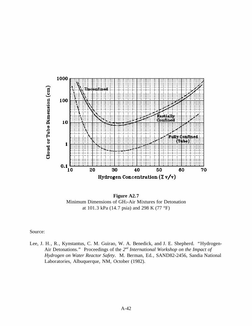
A-42
Figure A2.7Minimum Dimensions of GH2-Air Mixtures for Detonation
at 101.3 kPa (14.7 psia) and 298 K (77 °F)
Source:
Lee, J. H., R., Kynstantus, C. M. Guirao, W. A. Benedick, and J. E. Shepherd. “Hydrogen-Air Detonations.” Proceedings of the 2nd International Workshop on the Impact ofHydrogen on Water Reactor Safety. M. Berman, Ed., SAND82-2456, Sandia NationalLaboratories, Albuquerque, NM, October (1982).

A-43
Figure A2.8Detonation Cell Widths for Hydrogen-Air Mixtures at 101.3 kPa (14.7 psia)
Source:
Lee, J. H., R. Kynstantus, C. M. Guirao, W. A. Benedick, and J. E. Shepherd. “Hydrogen-Air Detonations.” Proceedings of the 2nd International Workshop on the Impact ofHydrogen on Water Reactor Safety. M. Berman, Ed., SAND82-2456, Sandia NationalLaboratories, Albuquerque, NM, October (1982).

A-44
Figure A2.9Minimum Initiation Energies for Direct Detonation of Hydrogen-Air Mixtures
Source:
Lee, J. H., R. Kynstantus, C. M. Guirao, W. A. Benedick, and J. E. Shepherd. “Hydrogen-Air Detonations.” Proceedings of the 2nd International Workshop on the Impact ofHydrogen on Water Reactor Safety. M. Berman, Ed., SAND82-2456, Sandia NationalLaboratories, Albuquerque, NM, October (1982).

A-45
Table A2.1Potential Ignition Sourcesa
ThermalIgnition
ElectricalIgnition
Personnel smoking Electrical short circuits, sparks, and arcsOpen flames Metal fractureShock waves from tank rupture Static electricity (two-phase flow)Fragments from bursting vessels Static electricity (flow with solid particles)Heating of high-velocity jets LightningWelding Generation of electrical charge byExplosive charges equipment operationsFriction and gallingResonance ignition (repeated shock waves in a flow system)Mechanical impactTensile ruptureMechanical vibrationExhaust from thermal combustion enginea Ordin, P. M. “Safety,” Chapter 1, Liquid Cryogens, Vol 1, Theory and Equipment. K. D.
Williamson, Jr. and F. J. Edeskuty, Eds., CRC Press, Boca Raton, FL (1983).

A-46
Table A2.2Flammability Limits
Upward Propagation Downward Propagation Horizontal PropagationLower Limit Upper Limit Lower Limit Upper Limit Lower
LimitUpper Limit
Hydrogen Content (vol %)
Hydrogen in air and oxygen at 101.3 kPa (14.7 psia):
H2 + air:Tubes 4.1 74.8 8.9 74.5 6.2 71.3Spherical Vessels 4.6 75.5 --- ---- --- ----
H2 + oxygen 4.1 94.0 4.1 92.0 --- ----
Hydrogen plus inert gas mixtures at 101.3 kPa (14.7 psia):
H2+He+21 vol% O2 7.7 75.7 8.7 75.7 --- ----
H2+CO2+21 vol%O2
5.3 69.8 13.1 69.8 --- ----
H2+N2+21 vol% O2 4.2 74.6 9.0 74.6 --- ----
Hydrogen in air at reduced pressure with a 45 mJ (47.5 Btu) ignition source:
Pressure (kPa) 25 cm Tube 2 L SphereLowerLimit
UpperLimit
LowerLimit
UpperLimit
20 ≈ 4 ≈ 56 ≈ 5 ≈ 52
10 ≈ 10 ≈ 42 ≈ 11 ≈ 35
7 ≈ 15 ≈ 33 ≈ 16 ≈ 27
6 20-30 20-25 (at 6.5 kPa)
Note: Dashes indicate no information available.
Source:
Benz, F. J., C. V. Bishop, and M. D. Pedley. Ignition and Thermal Hazards of SelectedAerospace Fluids: Overview, Data, and Procedures. NASA White Sands TestFacility, Las Cruces, NM (1988).

A-47
Table A2.3Effects of Diluentsa on Flammable Range for Hydrogen in Air
Tube Diameter,cm (in.)
Rating of Diluents at ReducingFlammable Range
Wide tubes CO2 <N2 <He <Arb
2.2 (0.87) CO2 <He <N2 <Arb
1.6 (0.63) He <CO2 <N2 <Arb
a Equal concentrationsb Ar is the least effective in reducing the flammable range.
Source:
Mellish, C. E. and J. W. Linnett. “The Influence of Inert Gases on Some FlamePhenomena.” Proceedings of the 4th Symposium (International) Combustion,Baltimore, MD (1953): pp. 407-420.

A-48
Table A2.4Inhibitor for Extinction of Hydrogen Diffusion Flames
Inhibitor Concentration at FlameExtinction (vol%)
Added to air:Nitrogen 94.1CH3Br 11.7CBrF3 17.7
Added to fuel:Nitrogen 52.4CH3Br 58.1CBrF3 56.6
Source:
Creitz, E. C. “Inhibition of Diffusion Flames by Methyl Bromide and Trifluoromethyl-Bromide Applied to the Fuel and Oxygen Sides of the Reaction Zone.” Journal ofResearch for Applied Physics and Chemistry, 65A (1961): pp. 389-396.

A-49
Table A2.5Critical Radiant Flux Levels
Radiant flux W/cm2 (Btu/h/ft2) Effect
0.473 (1500) Pain felt in 15-30 s (skin burns in 30 s)1.167 (3700) Thin steel with insulated backing can
undergo failure1.260 (4000) Minimum flux - wood ignition2.30 (7300) Uninsulated steel - undergoes structural
failure5.86 (18000) Fiber insulating board - ignition after 3 s
exposure4.35 (14000) Fiber insulating board - ignition after 7 s
exposure3.35 (11000) Cotton fabrics - ignition after 7 s exposure
NOTE: Safe limit for extended exposure - 0.139 W/cm2
(440 Btu/h/ft2). For exposures from 10-30 s:1st degree burns ≈ 2-4 cal/cm2 or 8.4-16.7 J/cm2 (0.0051-0.102 Btu/in2)2nd degree burns ≈ 4-8 cal/cm2 or 8.4-16.7 J/cm2 (0.0051-0.102 Btu/in2).
Source:
Ordin, P. M. “Safety,” Chapter 1, Liquid Cryogens, Vol 1, Theory and Equipment, K. D.Williamson, Jr. and F. J. Edeskuty, Eds. CRC Press, Boca Raton, FL (1983).

A-51
A.3 HYDROGEN STORAGE SITING

A-53
Table A3.1Order of Preference for Location of GH2 Storage Systemsa,b
GH2 Volume
Nature of LocationLess Than3000 ft3
(85 m3)
3000 to15000 ft3
(85 to 425 m3)
Over15000 ft3
(425 m3)
Outdoors I I IIn separate building II II IIIn special room III III Not permittedInside buildings, but
not in a special roomand exposed to otheroccupancies.
IV Not permitted Not permitted
a 29 CFR 1910.103 (1996) and NFPA 50A (1994)b The location of GH2 storage, as determined by the maximum total quantity of GH2,
shall be in the order of preference indicated by Roman numerals with I indicatingthe most preferred and IV the least preferred location.
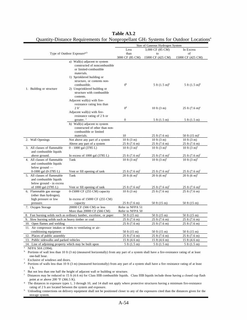
A-54
Table A3.2Quantity-Distance Requirements for Nonpropellant GH2 Systems for Outdoor Locationsa
Size of Gaseous Hydrogen System
Type of Outdoor Exposureg,hLessthan
3000 CF (85 CM)
3,000 CF (85 CM)to
15000 CF (425 CM)
In Excessof
15000 CF (425 CM)a) Wall(s) adjacent to system
constructed of noncombustibleor limited-combustiblematerials.
1) Sprinklered building orstructure, or contents non-combustible. 0b 5 ft (1.5 m)b 5 ft (1.5 m)b
1. Building or structure 2) Unsprinklered building orstructure with combustiblecontents.
Adjacent wall(s) with fire-resistance rating less than2 hc 0d 10 ft (3 m) 25 ft (7.6 m)e
Adjacent wall(s) with fire-resistance rating of 2 h orgreater. c 0 5 ft (1.5 m) 5 ft (1.5 m)
b) Wall(s) adjacent to systemconstructed of other than non-combustible or limitedmaterials. 10 25 ft (7.6 m) 50 ft (15 m)e
2. Wall Openings Not above any part of a systemAbove any part of a system
10 ft (3 m)25 ft (7.6 m)
10 ft (3 m)25 ft (7.6 m)
10 ft (3 m)25 ft (7.6 m)
3. All classes of flammableand combustible liquidsabove ground.
0 - 1000 gal (3785 L)
In excess of 1000 gal (3785 L)
10 ft (3 m)f
25 ft (7.6 m)f
10 ft (3 m)f
25 ft (7.6 m)f
10 ft (3 m)f
25 ft (7.6 m)f
4. All classes of flammableand combustible liquidsbelow ground —0-1000 gal (0-3785 L)
Tank
Vent or fill opening of tank
10 ft (3 m)f
25 ft (7.6 m)f
10 ft (3 m)f
25 ft (7.6 m)f
10 ft (3 m)f
25 ft (7.6 m)f
5. All classes of flammableand combustible liquidsbelow ground - in excessof 1000 gal (3785 L)
Tank
Vent or fill opening of tank
20 ft (6 m)f
25 ft (7.6 m)f
20 ft (6 m)f
25 ft (7.6 m)f
20 ft (6 m)f
25 ft (7.6 m)f
6. Flammable gas storage(other than hydrogen),high pressure or lowpressure.
0-15000 CF (255 CM) capacity
In excess of 15000 CF (255 CM)capacity
10 ft (3 m)
25 ft (7.6 m)
25 ft (7.6 m)
50 ft (15 m)
25 ft (7.6 m)
50 ft (15 m)7. Oxygen Storage 20000 CF (566 CM) or less
More than 20000 CF (566 CM)Refer to NFPA 51Refer to NFPA 50
8. Fast burning solids such as ordinary lumber, excelsior, or paper 50 ft (15 m) 50 ft (15 m) 50 ft (15 m)9. Slow burning solids such as heavy timber or coal 25 ft (7.6 m) 25 ft (7.6 m) 25 ft (7.6 m)10. Open flames and welding 25 ft (7.6 m) 25 ft (7.6 m) 25 ft (7.6 m)11. Air compressor intakes or inlets to ventilating or air-
conditioning equipment 50 ft (15 m) 50 ft (15 m) 50 ft (15 m)12. Places of public assembly 25 ft (7.6 m) 25 ft (7.6 m) 25 ft (7.6 m)13. Public sidewalks and parked vehicles 15 ft (4.6 m) 15 ft (4.6 m) 15 ft (4.6 m)14. Line of adjoining property which may be built upon 5 ft (1.5 m) 5 ft (1.5 m) 5 ft (1.5 m)
a NFPA 50A (1994).b Portions of wall less than 10 ft (3 m) (measured horizontally) from any part of a system shall have a fire-resistance rating of at least
one-half hour.c Exclusive of windows and doors.d Portions of walls less than 10 ft (3 m) (measured horizontally) from any part of a system shall have a fire resistance rating of at least
1 h.e But not less than one half the height of adjacent wall or building or structure.f Distances may be reduced to 15 ft (4.6 m) for Class IIIB combustible liquids. Class IIIB liquids include those having a closed cup flash
point at or above 200 °F (366.5 K).g The distances in exposure types 1, 3 through 10, and 14 shall not apply where protective structures having a minimum fire-resistance
rating of 2 h are located between the system and exposure.h Unloading connections on delivery equipment shall not be positioned closer to any of the exposures cited than the distances given for the
storage system.

A-55
Table A3.3Order of Preference for Location of LH2 Storage Systemsa, b, c
LH2 Volume, L (gal)
Nature of Location150 (39.63)
to189 (50)
190 (51)to
1136 (300)
1137 (301)to
2271 (600)
In excessof
2271 (600)
Outdoors I I I IIn separate building II II II Not permittedIn special room III III Not permitted Not permittedInside buildings, but not
in a special room andexposed to otheroccupancies.
IV Not permitted Not permitted Not permitted
a 29 CFR 1910.103 and NFPA 50B (1994).b This table does not apply to the storage in dewars of the type generally used in laboratories for experimental purposes.c The location of LH2 storage, as determined by the maximum total quantity of LH2, shall be in the order of preference indicated
by Roman numerals with I indicating the most preferred and IV the least preferred location.

A-56
Table A3.4Quantity-Distancea Requirements for Nonpropellant LH2 Systems for Outdoor Locationsb,c
Total Liquid Hydrogen StorageCapacity (gal)
Type of Outdoor Exposureh
39.65to
3500
3501to
15,000
15,001to
75,000
1. Building/structurea) Wall(s) adjacent to system constructed of non combustible
materials or limited combustible materials.(1) Sprinklered building/structure or unsprinklered
building/structure having noncombustible contents.(2) Unsprinklered building/structure with combustible
contents. Adjacent wall(s) with fire resistance rating lessthan 3 hr.e
Adjacent wall(s) with fire resistance rating of 3 hr orgreater.e
b) Wall(s) adjacent to system constructed of combustiblematerials(1) Sprinklered building/structure(2) Unsprinklered building/structure
5d,f
255
5050
5 d,f
505
5075
5 d,f
755
50100
2. Wall openingsa) Openableb) Unopenable
7525
7550
7550
3. Air compressor intakes, inlets for air conditioning or ventilatingequipment. 75 75 75
4. All classes of flammable and combustible liquids (above groundand vent or fill openings if below ground). 50g 75g 100g
5. Between stationary liquefied hydrogen containers 5 5 56. Flammable gas storage (other than hydrogen 50 75 757. Liquid oxygen storage and other oxidizers 75 75 758. Combustible solids 50 75 1009. Open flames and welding 50 50 5010. Places of public assembly 75 75 7511. Public ways, railroads, and property lines 25 50 7512. Inlet to underground sewers 5 5 513. Protective structures 5f 5f 5f
a Distances are given in units of feet.b NFPA 50B (1994).c The distances in exposure types 1, 4, 6, 7, 8, and 11 shall be permitted to be reduced by two thirds, but to not less
than 5 ft (1.5 m), for insulated portions of the system; and, for uninsulated portions of the system, by the use ofprotective structures having a minimum fire resistance rating of 2 h, which interrupts the line of sight between theuninsulated portions of the LH2 system and the exposure. The protective structure, or the insulated LH2 tank, shallinterrupt the line of sight between uninsulated portions of the LH2 storage system and the exposure.
d Portions of wall less than 10 ft (3 m) (measured horizontally) from any part of a system shall have a fire resistancerating of at least one-half hour.
e Exclusive of windows and doors.f Where protective structures are provided, ventilation and confinement of product shall be considered. The 5 ft (1.5 m)
distance in exposure types 1 and 13 facilitates maintenance and enhances ventilation.g Distances may be reduced to 15 ft (4.6 m) for Class IIIB combustible liquids (liquids having a flash point at or above
366.5 K (200 °F).h Unloading connections on delivery equipment shall not be positioned closer to any of the exposures cited than the
distances given for the storage system.

A-57
Table A3.5Liquid Propellant Hazard and Compatibility Groupsf
StorageHazard Compatibility
Propellant Groupa Groupb
Alcohols (CH3OH, C2H5OH, and (CH3)2CHOH) I CAnhydrous ammonia (NH3) I CAniline (C6H5NH2) I CHydrocarbon fuels (JP-4, JP-5, and RP-1) I CMonopropellant (NOS-58-6) I CNitrogen tetroxide (N2O4) I AOtto fuel II I GRed fuming nitric acid (HNO3) I ATriethylboron (B(C2H5)3) I DBromine pentafluoride (BrF5) II AChlorine triflouride (C1F3) II AHydrogen peroxide (H2O2) greater than 52% IIc ALiquid fluorine (LF2) II ALiquid oxygen (LO2) II APerchloryl fluoride (C1O3F) II AOxygen difluoride (OF2) II AOzone difluoride (O2F2) II AEthylene oxide (C2H4O) III DHydrazine (N2H4) III CHydrazine and unsymmetrical dimethyl-hydrazine
(UDMH) mixtures III CLiquid hydrogen (LH2) III CMixed amine fuels III CMonomethylhydrazine (CH2NHNH3) III CPentaborine (B5H9) III DUDMH ((CH3)2NNH2) III CNitromethane (CH3NO2) IVd Fe
Tetranitromethane (C(NO2)4) IV F
a The toxic hazard may be an overriding consideration for some materials listed. Consult applicableregulations and, if necessary, other authorities or publications for toxic siting criteria.
b Propellants with same compatibility group letter are considered as compatible propellants and those withunlike letters incompatible.
c Concentrations of hydrogen peroxide greater than 90% can detonate under certain conditions. However,its sensitivity to detonation is no greater than that of standard energetic double base solid propellant underthe same conditions.
d Technical grade or better nitromethane in unit quantities of 55 gal (208 L) or less in DOT 17E or C drumsmay be stored using hazard group II distances provided drums are stored only one tier high, drums areprotected from direct rays of the sun, and a maximum storage life of 2 years is enforced unless storagelife tests indicate that products meet purchase specifications at that time. Such tests are to be repeated at1-year intervals thereafter.
e Nitromethane is chemically compatible with storage compatibility group C liquid propellants; however,differences in hazards require nitromethane be stored separately.
f DoD 6055.9 (1992), NSS 1740.12 (1993).

A-58
Table A3.6Explosive Equivalent Factors for Liquid Propellantsa, b
Propellant Combinations Static Test Stands Range Launch Pads
LO2 /LH2 60% 60%
LO2 /LH2 + LO2/RP-1d 60% for LO2 /LH2
+ 10% for LO2/RP-1d60% for LO2 /LH2
+ 20% for LO2/RP-1d
a NSS 1740.12 (1993), DoD 6055.9 (1992).b The percentage factors given in the table are to be used to determine the equivalencies of propellant mixtures at static test
stands and range launch pads when such propellants are located above ground and are unconfined except for their tankage.Other configurations shall be considered on an individual basis to determine the equivalencies.
c For quantities of propellant up to but not over the equivalent of 45 kg (100 lb) of explosives, the distance shall be determinedon an individual basis by the authority having jurisdiction at the controlling NASA center. All personnel and facilities,involved in the operation or not, shall be adequately protected by proper operating procedures, equipment design, shielding,barricading, or other suitable means.
d Alcohols or other hydrocarbons may be substituted for RP-1.
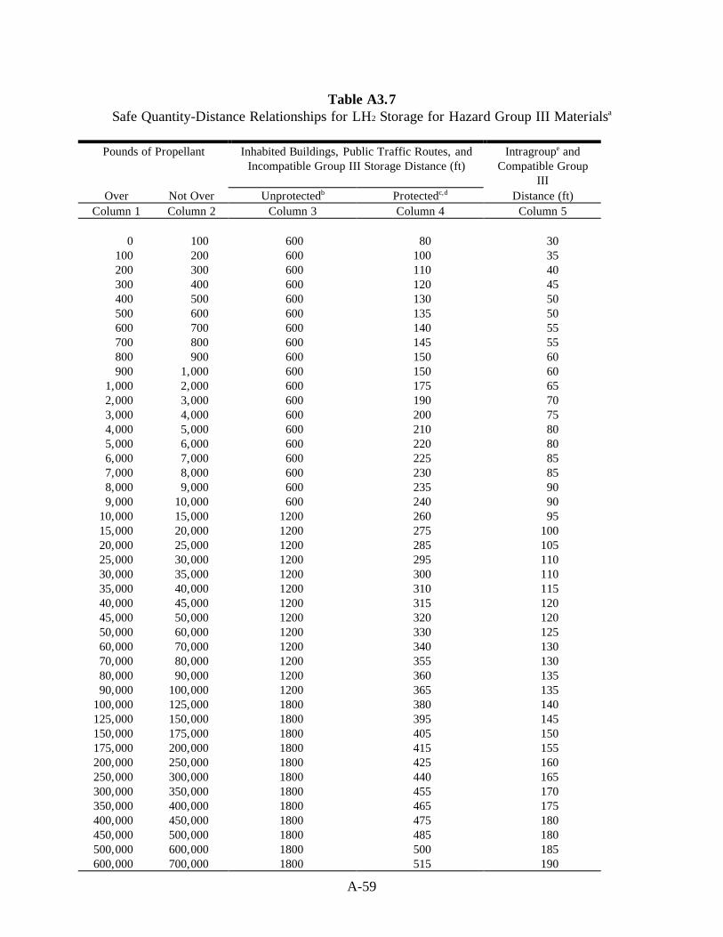
A-59
Table A3.7Safe Quantity-Distance Relationships for LH2 Storage for Hazard Group III Materialsa
Pounds of Propellant Inhabited Buildings, Public Traffic Routes, andIncompatible Group III Storage Distance (ft)
Intragroupe andCompatible Group
IIIOver Not Over Unprotectedb Protectedc,d Distance (ft)
Column 1 Column 2 Column 3 Column 4 Column 5
0 100 600 80 30100 200 600 100 35200 300 600 110 40300 400 600 120 45400 500 600 130 50500 600 600 135 50600 700 600 140 55700 800 600 145 55800 900 600 150 60900 1,000 600 150 60
1,000 2,000 600 175 652,000 3,000 600 190 703,000 4,000 600 200 754,000 5,000 600 210 805,000 6,000 600 220 806,000 7,000 600 225 857,000 8,000 600 230 858,000 9,000 600 235 909,000 10,000 600 240 90
10,000 15,000 1200 260 9515,000 20,000 1200 275 10020,000 25,000 1200 285 10525,000 30,000 1200 295 11030,000 35,000 1200 300 11035,000 40,000 1200 310 11540,000 45,000 1200 315 12045,000 50,000 1200 320 12050,000 60,000 1200 330 12560,000 70,000 1200 340 13070,000 80,000 1200 355 13080,000 90,000 1200 360 13590,000 100,000 1200 365 135
100,000 125,000 1800 380 140125,000 150,000 1800 395 145150,000 175,000 1800 405 150175,000 200,000 1800 415 155200,000 250,000 1800 425 160250,000 300,000 1800 440 165300,000 350,000 1800 455 170350,000 400,000 1800 465 175400,000 450,000 1800 475 180450,000 500,000 1800 485 180500,000 600,000 1800 500 185600,000 700,000 1800 515 190
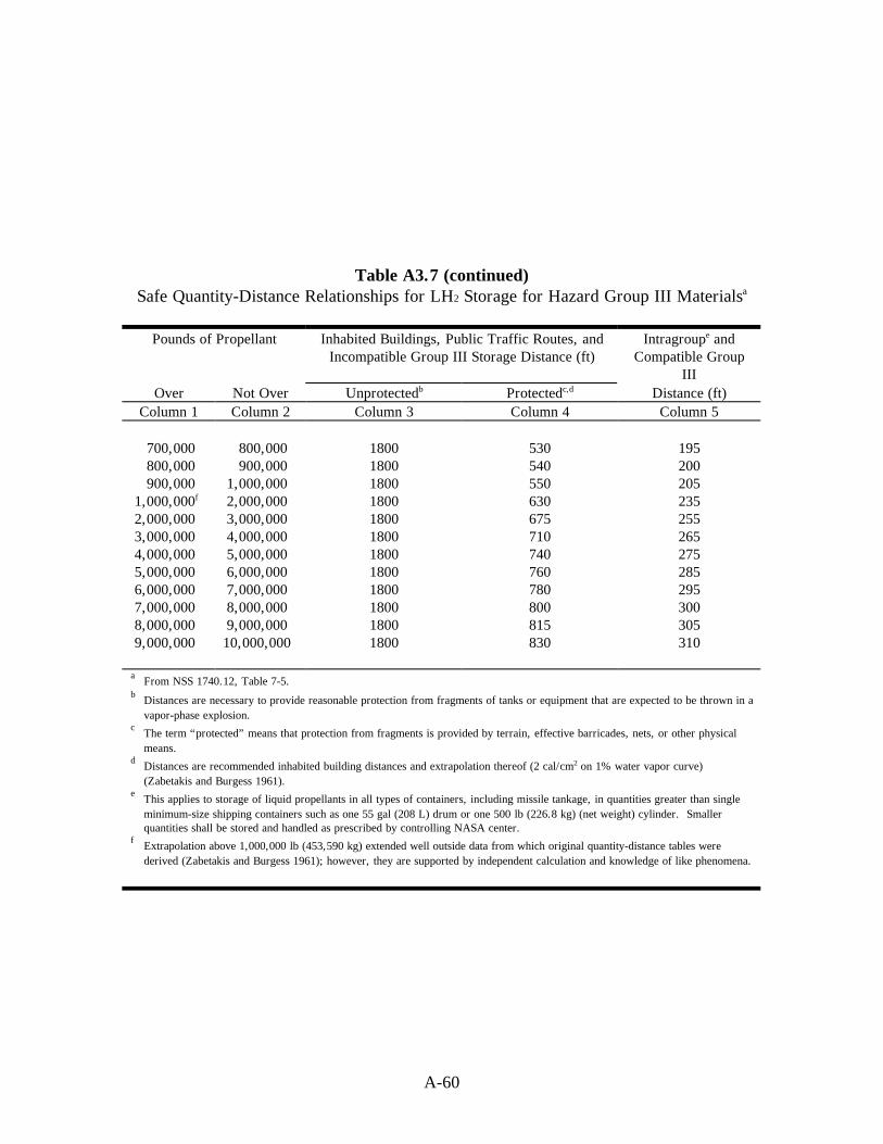
A-60
Table A3.7 (continued)Safe Quantity-Distance Relationships for LH2 Storage for Hazard Group III Materialsa
Pounds of Propellant Inhabited Buildings, Public Traffic Routes, andIncompatible Group III Storage Distance (ft)
Intragroupe andCompatible Group
IIIOver Not Over Unprotectedb Protectedc,d Distance (ft)
Column 1 Column 2 Column 3 Column 4 Column 5
700,000 800,000 1800 530 195800,000 900,000 1800 540 200900,000 1,000,000 1800 550 205
1,000,000f 2,000,000 1800 630 2352,000,000 3,000,000 1800 675 2553,000,000 4,000,000 1800 710 2654,000,000 5,000,000 1800 740 2755,000,000 6,000,000 1800 760 2856,000,000 7,000,000 1800 780 2957,000,000 8,000,000 1800 800 3008,000,000 9,000,000 1800 815 3059,000,000 10,000,000 1800 830 310
a From NSS 1740.12, Table 7-5.b Distances are necessary to provide reasonable protection from fragments of tanks or equipment that are expected to be thrown in a
vapor-phase explosion.c The term “protected” means that protection from fragments is provided by terrain, effective barricades, nets, or other physical
means.d Distances are recommended inhabited building distances and extrapolation thereof (2 cal/cm2 on 1% water vapor curve)
(Zabetakis and Burgess 1961).e This applies to storage of liquid propellants in all types of containers, including missile tankage, in quantities greater than single
minimum-size shipping containers such as one 55 gal (208 L) drum or one 500 lb (226.8 kg) (net weight) cylinder. Smallerquantities shall be stored and handled as prescribed by controlling NASA center.
f Extrapolation above 1,000,000 lb (453,590 kg) extended well outside data from which original quantity-distance tables werederived (Zabetakis and Burgess 1961); however, they are supported by independent calculation and knowledge of like phenomena.

A-61
Table A3.8Separation and Intraline Quantity-Distance Values for Mixed Propellantsa
Weight of Explosives Distance from Propellant and Explosives Hazard (ft)or Group IV To Inhabited To Public Intraline
Propellant (lb) Buildings Traffic Routes Barricaded UnbarricadedColumn 1 Column 2 Column 3 Column 4 Column 5
<100 ---b ---b ---b ---b
>100 190 115 40 80200 235 140 50 100300 270 160 60 120400 295 175 65 130500 320 190 70 140600 340 205 75 150700 355 215 80 160800 375 225 85 170900 390 235 90 180
1,000 400 240 95 1901,500 460 275 105 2102,000 505 305 115 2303,000 580 350 130 2604,000 635 380 140 2805,000 685 410 150 3006,000 730 440 160 3207,000 770 460 170 3408,000 800 480 180 3609,000 835 500 190 380
10,000 865 520 200 40015,000 990 595 225 45020,000 1090 655 245 49025,000 1170 700 265 53030,000 1245 745 280 56035,000 1310 785 295 59040,000 1370 820 310 62045,000 1425 855 320 64050,000 1475 885 330 66055,000 1520 910 340 68060,000 1565 940 350 70065,000 1610 965 360 72070,000 1650 990 370 74075,000 1685 1010 385 77080,000 1725 1035 390 78085,000 1760 1055 395 79090,000 1795 1075 400 80095,000 1825 1095 410 820
100,000 1855 1115 415 830125,000 2115 1270 450 900150,000 2350 1410 475 950175,000 2565 1540 500 1000200,000 2770 1660 525 1050
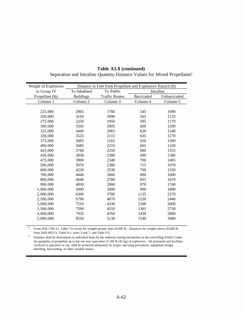
A-62
Table A3.8 (continued)Separation and Intraline Quantity-Distance Values for Mixed Propellantsa
Weight of Explosives Distance in Feet from Propellant and Explosives Hazard (ft)or Group IV To Inhabited To Public Intraline
Propellant (lb) Buildings Traffic Routes Barricaded UnbarricadedColumn 1 Column 2 Column 3 Column 4 Column 5
225,000 2965 1780 545 1090250,000 3150 1890 565 1135275,000 3250 1950 585 1170300,000 3345 2005 600 1200325,000 3440 2065 620 1240350,000 3525 2115 635 1270375,000 3605 2165 650 1300400,000 3685 2210 665 1330425,000 3760 2250 680 1355450,000 3830 2300 690 1380475,000 3900 2340 700 1405500,000 3970 2380 715 1670600,000 4220 2530 760 1520700,000 4440 2660 800 1600800,000 4640 2780 835 1670900,000 4830 2900 870 1740
1,000,000 5000 3000 900 18002,000,000 6300 3780 1135 22702,500,000 6790 4070 1220 24403,000,000 7210 4330 1300 26003,500,000 7590 4550 1365 27304,000,000 7935 4760 1430 28605,000,000 8550 5130 1540 3080
a From NSS 1740.12, Table 7-6 except for weights greater than 20,000 lb. Distances for weights above 20,000 lbfrom DoD 6055.9, Table 9-1, notes 3 and 7, and Table 9-3.
b Distance shall be determined on individual basis by the authority having jurisdiction at the controlling NASA Centerfor quantities of propellant up to but not over equivalent of 100 lb (45 kg) of explosives. All personnel and facilities,involved in operation or not, shall be protected adequately by proper operating procedures, equipment design,shielding, barricading, or other suitable means.

A.4 VENTING AND FLOW OF HYDROGEN

A-65
Figure A4.1Flame Dip as a Function of Stack Diameter and Hydrogen Flow
Source:
Grumer, J., A Strasser, J. M. Singer, P. M. Gussey, and V. R. Rowe, “Hydrogen Flare StackDiffusion Flames: Low and High Flow Instabilities, Burning Rates, Dilution Limits,Temperatures, and Wind Effects,” BM-RI-7457, Bureau of Mines Report of Investigation(1970)
Peterson, P., “Explosions in Flare Stacks.” Chemical Eng. Prog., 63(8), August (1967):pp. 67-70.

A-66
Figure A4.2Blowout and Stable Flame Region
Source:
Brzustowski, T. A., S. R. Gollahalli, and H. F. Sullivan, “The Turbulent Hydrogen DiffusionFlame in a Cross-Wind,” Comb. Sci. Tech., 11(1-2), (1975) pp. 20-33.
Ordin, P. M., and R. C. Carter, “ Clinch River Breeder Reactor Hydrogen Disposal andIgnition System,” ARSD-00093, General Electric, June (1980).

A-67
Figure A4.3Flame Shape in Crosswinds
Source:
Brzustowski, T. A., S R. Gollahalli, and H. F. Sullivan, “The Turbulent Hydrogen DiffusionFlame in a Cross-Wind,” Comb. Sci. Tech., 11(1-2), (1975).
Ordin, P. M., and R. C. Carter, “ Clinch River Breeder Reactor Hydrogen Disposal andIgnition System,” ARSD-00093, General Electric, June (1980).

A-68
Figure A4.4Minimum Flow Rate for Non-Stratified, Two Phase Hydrogen andNitrogen Flow for Pipeline Fluid Qualities Below 95% and 98%a
a Liquid and gas phases assumed saturated at normal boiling point.
Source:
Liebenberg, D. H., J. K. Novak, and F. J. Edeskuty. “Cooldown of Cryogenic TransferSystems.” AIAA 3rd Propulsion Joint Specialist Conference, AIAA Paper No. 67-475,Washington, DC, July 17-21 (1967).
Novak, J. K. “Cooldown Flow Rate Limits Imposed by Thermal Stresses in Liquid Hydrogenor Nitrogen Pipelines.” Advances in Cryogenic Engineering, Vol. 15, K. D.Timmerhaus, Ed., Plenum Press, New York (1970): pp. 346-353.

A-69
Figure A4.5Liquid Hydrogen Flow Rate Limits to Avoid Excessive Cooldown Stresses
in Thick-wall Piping Sections such as Flanges for 304 SS and 6061 Al
t = maximum radial thickness of flange wall (cm)D = inside diameter of flange (cm)Wmax = cooldown flow rate limit (kg/s)
Upper and lower estimates represent difference in variables such as heat transfercorrelation and limiting stress values.
Source:
Novak, J. K. “Cooldown Flow Rate Limits Imposed by Thermal Stresses in Liquid Hydrogenor Nitrogen Pipelines.” Advances in Cryogenic Engineering, Vol. 15, K. D.Timmerhaus, Ed., Plenum Press, New York, (1970): pp. 346-353
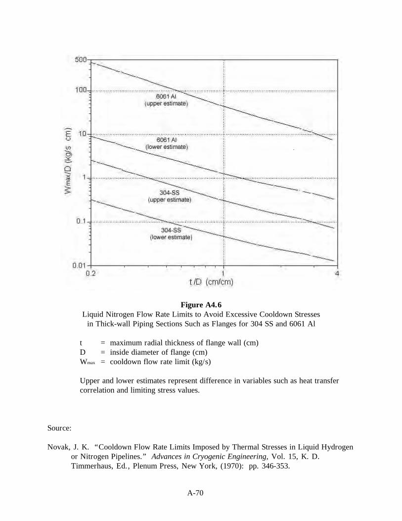
A-70
Figure A4.6Liquid Nitrogen Flow Rate Limits to Avoid Excessive Cooldown Stresses
in Thick-wall Piping Sections Such as Flanges for 304 SS and 6061 Al
t = maximum radial thickness of flange wall (cm)D = inside diameter of flange (cm)Wmax = cooldown flow rate limit (kg/s)
Upper and lower estimates represent difference in variables such as heat transfercorrelation and limiting stress values.
Source:
Novak, J. K. “Cooldown Flow Rate Limits Imposed by Thermal Stresses in Liquid Hydrogenor Nitrogen Pipelines.” Advances in Cryogenic Engineering, Vol. 15, K. D.Timmerhaus, Ed., Plenum Press, New York, (1970): pp. 346-353.

A-71
Table A4.1Summary of Liquefied Hydrogen Spill Data
Size ofspill(gal) Surface Vaporization Dispersal Ignition Radiation
AD 324/94 a
0.18 Paraffin wax Yes No No No1.8 Macadam No Visible cloud
rise onlyNo No
1.8 Gravel No Visible cloudrise only
No No
14.4 Gravel No No Yes Flame size only15.4 Steel No No Yes Flame size only
.8 Macadam No Vertical concentrationsin quiescent atmosphere
No No
2.0-23.6 Gravel No No Yes Flame size andradiant heat flux
BM-RI-5707b
23.5-44.4 Sand Yes No No No35.2 Bank Gravel Yes No No No25.0-50.0 Crushed rock Yes No No No1.3 Sand Average Observations of visible
vaporization time cloudYes Fireball size only
32.0 Sand Average Observations of visible No Fireball size onlyvaporization time cloud
500.0 Sand Average Observations of visiblevaporization time cloud
No Fireball sizeand radiant heatflux
5000.0 Sand No No Yesc Fireball sizeand radiant heatflux
a A. D. Little, Inc., “An Investigation of Hazards Associated with the Storage and Handling ofLiquid Hydrogen,” AD 324/94, A. D. Little, Inc., Cambridge, MA, March (1960).
b Zebetakis, M. G., and D. S. Burgess, “Research on the Hazards Associated with the Productionand Handling of Liquid Hydrogen,” BM-RI-5707, Bureau of Mines Report of Investigation(1961).
c Inadvertently

A.5 MATERIALS
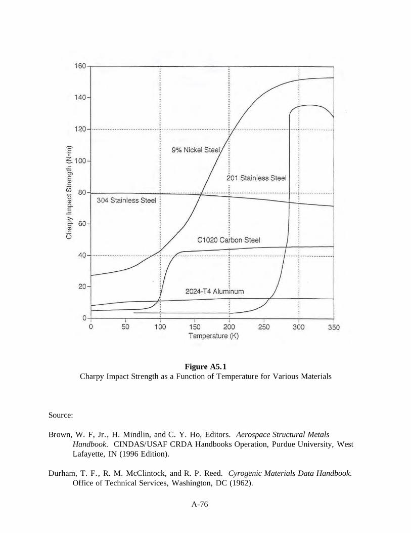
A-76
Figure A5.1Charpy Impact Strength as a Function of Temperature for Various Materials
Source:
Brown, W. F, Jr., H. Mindlin, and C. Y. Ho, Editors. Aerospace Structural MetalsHandbook. CINDAS/USAF CRDA Handbooks Operation, Purdue University, WestLafayette, IN (1996 Edition).
Durham, T. F., R. M. McClintock, and R. P. Reed. Cyrogenic Materials Data Handbook. Office of Technical Services, Washington, DC (1962).

A-78
Figure A5.2Yield and Tensile Stress of 5086 Aluminum as a Function of Temperature
Source:
McClintock, R. M., and H. P. Gibbons. Mechanical Properties of Structural Materials atLow Temperatures, A Complilation from the Literature. National Bureau of Standards,Monograph 13, United States Department of Commerce, Washington, DC (1960).

A-80
Figure A5.3Yield and Tensile Stress of AISI 430 Stainless Steel as a Function of Temperature
Source:
McClintock, R. M., and H. P. Gibbons. Mechanical Properties of Structural Materials atLow Temperatures, A Compilation from the Literature. National Bureau of Standards,Monograph 13, United States Department of Commerce, Washington, DC (1960).

A-82
Figure A5.4Thermal Expansion Coefficient of Copper as a Function of Temperature
Source:
Johnson, V. J., Ed.. A Compendium of the Properties of Materials at Low Temperature(Phase I),” WADD Technical Report 60-56, Part II, Properties of Solids, Office ofTechnical Services, United States Department of Commerce, Washington, DC (1960).

A-84
PTFE = Polytetrafluoroethylene (Teflon)
Figure A5.5Total Linear Thermal Contraction as a Function of Temperature
for Several Materials Showing the Total Contraction at a Given Temperatureas the Temperature is Lowered from 300 K (80 °F) to that Temperature
Source:
Wigley, D. A. and P. Halford. “Materials of Construction and Techniques of Fabrication.”Cyrogenic Fundamentals, G. G. Haselden, Ed., chapter 6, Academic Press, London(1971).

A-85
Table A5.1Summary of Material Compatability for Hydrogen Service
ServiceMaterial GH2 LH2 SLH2 Remarks
Aluminum and its alloys Yes Yes Yes Austenitic stainless steels with > 7%
nickel (such as, 304, 304L, 308, 316,321, 347)
Yes Yes YesSome make martensitic conversion ifstressed above yield point at lowtemperature.
Carbon steels Yes No No Too brittle for cryogenic service. Copper and its alloys (such as, brass,
bronze, and copper-nickel)Yes Yes Yes
Gray, ductile, or cast iron No No No Not permitted for hydrogen service. Low-allow steels Yes No No Too brittle for cryogenic service. Nickel and its alloys (such as, Inconel and Monel)
No Yes Yes Susceptible to hydrogenembrittlement
Nickel steels (such as, 2.25, 3.5, 5, and9 % Ni)
No No No Ductility lost at LH2 and SLH2temperatures.
Titanium and its alloys Yes Yes Yes
Asbestos impregnated with Teflon Yes Yes Yes Avoid use because of carcinogenichazard.
Chloroprene rubber (Neoprene) Yes No No Too brittle for cryogenic service. Dacron Yes No No Too brittle for cryogenic service. Fluorocarbon rubber (Viton) Yes No No Too brittle for cryogenic service. Mylar Yes No No Too brittle for cryogenic service. Nitrile (Buna-N) Yes No No Too brittle for cryogenic service. Polyamides (Nylon) Yes No No Too brittle for cryogenic service. Polychlorotrifluorethylene (Kel-F) Yes Yes Yes Polytetrafluorethylene (Teflon) Yes Yes Yes

A-86
Table A5.2A Selection of Recommended Materials for Typical Applicationsa
Typical materialsApplication LH2 or SLH2 GH2
Valves Forged, machined, and cast valve bodies (304 or316 stainless steel, or brass) with extendedbonnet, and with other materials inside
Appropriate industrial productsb
Fittings Stainless steel bayonet type for vacuum jackets Appropriate industrial productsb
O-rings Stainless steelc, Kel-F, or Teflon Appropriate industrial productsb
Gaskets Soft Aluminum, lead, or annealed copperbetween serrated flanges; Kel-F; Teflon;glass-filled Teflon
Appropriate industrial productsb
Flexible hoses Convoluted vacuum jacketed 316 or321 stainless steel
Stainless steel braided with Teflon-lining
Rupture diskassembly
304, 304L, 316, or 316L stainless steel 304, 304L, 316, or 316L stainless steel
Piping 304, 304L, 316, or 316L stainless steel 300 series stainless steel (316preferredh)Carbon steelg
Dewars 304, 304L, 316, or 316L stainless steel Not applicableLubricants No lubricants used in some applications.h
Lubricants listed for GH2 are compatible butwill become solid at low temperatures. Drylubricants, such as PTFE, PTFE carbon, PTFEbronze, fiberglass-PFTE graphite.e Graphite andmolybdenum disulfide permit only very limitedservice life for bearings. f
Dupont Krytox 240AC, FluoramicsOXY-8, Dow Corning DC-33, DowCorning FS-3452, Bray Oil Braycote601, General Electric Versilube,Houghton Cosmolube 5100, Braycote640 AC, Dupont GPL 206, HalocarbonSeries 6.3 oil, and Kel-F oil
a Adapted from Table 6.1, Recommended Materials for Hydrogen Systems, in “Hydrogen Propellant,” Chapter 6 in Lewis SafetyManual, NASA Technical Memorandum 104438, November (1992): pp. 6-70.
b A number of standard industrial products are available covering a wide range of temperatures and pressures in a variety ofcompatible materials.
c Metal O-rings have proven satisfactory when coated with a soft material and when used on smooth surfaces. Type 321 stainlesssteel, with a coating of teflon or silver, should be used in stainless steel flanges with stainless bolting. Teflon coated aluminumshould be used in aluminum flanges with aluminum bolting. Using similar materials avoids the leakage possibility from unequalcontraction of dissimilar metals. (Lewis Hydrogen Safety Manual, December 10, (1959) pp. 3-18)
d Threaded joints should be avoided in LH2 or SLH2 systems. If they must be used, the male and female threads should be tinnedwith a 60% lead-40% tin solder, then heated to provide a soldered joint with pipe thread strength. (Lewis Hydrogen Safety Manual,December 10, (1959) pp. 3-15)
e W. Peschka, Liquid Hydrogen, Fuel of the Future, Springer-Verlag Wien, New York, (1992): pp. 197.
f D. A. Wigley, “The Properties of Nonmetals,” In Mechanical Properties of Materials at Low Temperature, Chapter 4, pp. 225,Plenum Press, New York 1971
g Carbon steel meeting ANSI/ASME B31.3 standards may be used for GH2 service above 244 K (-20 °F.) (Lewis Safety Manual,Chapter 6 “Hydrogen Propellant,” NASA Technical Memorandum 104438, November (1992): pp. 6-35.)
h McPherson, B., Private communication (1996).

A-87
Table A5.3Minimum Temperatures and Basic Allowable Stresses in Tension for Selected Metalsa
Metaland/orAlloyb Metal Formc
MinimumTemperatured
[K (°F)]
SpecifiedMinimumTensileStrength
[MPa (ksi)]
SpecifiedMinimum
YieldStrength
[MPa (ksi)]
BasicAllowable
Stresse
[MPa (ksi)]
Aluminum Alloy
WP1100-0, B361 forging & fitting 4.2 (-452) 75.8 (11) 20.7 (3) 13.8 (2.0) 1100-0, B241 pipe & tube 4.2 (-452) 75.8 (11) 20.7 (3) 13.8 (2.0) 3003-0, B241 pipe & tube 4.2 (-452) 96.5 (14) 34.5 (5) 22.8 (3.3) 5083-0, B209 plate & sheet 4.2 (-452) 275.8 (40) 124.1 (18) 82.7 (12.0) 5083-0, B241 pipe & tube 4.2 (-452) 268.9 (39) 110.3 (16) 73.8 (10.7) WP6061-T6, B361 forging & fitting 4.2 (-452) 262.0 (38) 241.3 (35) 87.6 (12.7) 6061-T6, B241 pipe & tube 4.2 (-452) 262.0 (38) 241.3 (35) 87.6 (12.7)
Copper & Copper Alloy
Cu Forging, B283 forging 4.2 (-452) 227.5 (33) 75.8 (11) 50.3 (6.7) Cu Plate, B152 plate & sheet 4.2 (-452) 206.8 (30) 68.9 (10) 46.2 (5.8) Cu Pipe, B42, annealed pipe & tube 4.2 (-452) 206.8 (30) 62.1 (9) 41.4 (6.0) Red brass pipe pipe & tube 4.2 (-452) 275.8 (40) 82.7 (12) 55.2 (8.0) 90Cu-10Ni, B171 plate & sheet 4.2 (-452) 275.8 (40) 103.4 (15) 68.9 (10.0) 90Cu-10Ni, B466 pipe & tube 4.2 (-452) 262.0 (38) 89.6 (13) 60.0 (8.4) 70Cu-30Ni, B171 plate & sheet 4.2 (-452) 482.6 (70) 206.8 (30) 137.9 (20.0) 70Cu-30Ni, B466 pipe & tube 4.2 (-452) 344.7 (50) 124.1 (18) 82.7 (12.0)
Nickel & Nickel Alloy
Ni, B366 forging & fitting 74.8 (-325) 379.2 (55) 82.7 (12) 55.2 (8.0) Ni, B162 plate & sheet 74.8 (-325) 379.2 (55) 103.4 (15) 68.9 (10.0) Ni, B161 pipe & tube 74.8 (-325) 379.2 (55) 103.4 (15) 68.9 (10.0) Ni-Cu, B564 forging & fitting 74.8 (-325) 482.6 (70) 172.4 (25) 115.1 (16.7) Ni-Cu, B127 plate & sheet 74.8 (-325) 482.6 (70) 193.1 (28) 128.9 (18.7) Ni-Cu, B165 pipe & tube 74.8 (-325) 482.6 (70) 193.1 (28) 128.9 (18.7) Ni-Cr-Fe, B564 forging & fitting 74.8 (-325) 551.6 (80) 241.3 (35) 160.6 (23.3) Ni-Cr-Fe, B168 plate & sheet 74.8 (-325) 551.6 (80) 241.3 (35) 160.6 (23.3) Ni-Cr-Fe, B167 pipe & tube 74.8 (-325) 551.6 (80) 206.8 (30) 137.9 (20.0)
Steel, Carbon
A285 Grade C, plate & sheet ---- f 379.2 (55) 206.8 (30) 126.2 (18.3) A285 Grade C, A524 pipe & tube 244 (-20) 379.2 (55) 206.8 (30) 126.2 (18.3) A442 Grade 50, A672 pipe & tube ---- f 413.7 (60) 220.6 (32) 137.9 (20.0)
Steel, Low & Intermediate Alloy
3.5 Ni, A420 forging & fitting 172 (-150) 448.2 (65) 241.3 (35) 149.6 (21.7) 3.5 Ni, A203 plate 244 (-20) 448.2 (65) 255.1 (37) 149.6 (21.7) 3.5 Ni, A333 pipe & tube 172 (-150) 448.2 (65) 241.3 (35) 149.6 (21.7) 5 Ni, A645 plate 103 (-275) 655.0 (95) 448.2 (65) 218.6 (31.7) 9 Ni, A420 forging & fitting 77 (-320) 758.4 (110) 517.1 (75) 218.6 (31.7) 9 Ni, A353 plate 77 (-320) 689.5 (100) 517.1 (75) 218.6 (31.7) 9 Ni, A333 pipe & tube 77 (-320) 689.5 (100) 517.1 (75) 218.6 (31.7)

A-88
Table A5.3 (continued)Minimum Temperatures and Basic Allowable Stresses in Tension for Selected Metalsa
Metaland/orAlloyb Metal Formc
MinimumTemperatured
[K (°F)]
SpecifiedMinimumTensileStrength
[MPa (ksi)]
SpecifiedMinimum
YieldStrength
[MPa (ksi)]
BasicAllowable
Stresse
[MPa (ksi)]
Steel, Stainless, Ferritic
405 (12Cr-Al), A240 plate & sheet 244 (-20) 413.7 (60) 172.4 (25) 115.1 (16.7) 430 (17Cr), A240 plate & sheet 244 (-20) 448.2 (65) 206.8 (30) 137.9 (18.4)
Steel, Stainless, Martensitic
410 (13Cr), A240 plate & sheet 244 (-20) 448.2 (65) 206.8 (30) 126.9 (18.4)
Steel, Stainless, Austenitic
304 (18Cr-8Ni) plate & sheet 19.3 (-425) 517.1 (75) 206.8 (30) 137.9 (20.0) 304 pipe & tube 19.3 (-425) 517.1 (75) 206.8 (30) 137.9 (20.0) F304 (18Cr-8Ni) forging & fitting 19.3 (-425) 517.1 (75) 206.8 (30) 137.9 (20.0) 304L (18Cr-8Ni) plate & sheet 19.3 (-425) 482.6 (70) 172.4 (25) 115.1 (16.7) 304L pipe & tube 19.3 (-425) 482.6 (70) 172.4 (25) 115.1 (16.7) F304L (18Cr-8Ni) forging & fitting 19.3 (-425) 482.6 (70) 172.4 (25) 115.1 (16.7) 310 (25Cr-20Ni) plate & sheet 74.8 (-325) 517.1 (75) 206.8 (30) 137.9 (20.0) F310 (25Cr-20Ni) forging & fitting 74.8 (-325) 517.1 (75) 206.8 (30) 137.9 (20.0) 310S (25Cr-20Ni) plate & sheet 74.8 (-325) 517.1 (75) 206.8 (30) 137.9 (20.0) 310S pipe & tube 74.8 (-325) 517.1 (75) 206.8 (30) 137.9 (20.0) 316 (16Cr-12Ni-2Mo) plate & sheet 19.3 (-425) 517.1 (75) 206.8 (30) 137.9 (20.0) 316 pipe & tube 19.3 (-425) 517.1 (75) 206.8 (30) 137.9 (20.0) F316 (16Cr-12Ni-2Mo) forging & fitting 74.8 (-325) 517.1 (75) 206.8 (30) 137.9 (20.0) 316L (16Cr-12Ni-2Mo) plate & sheet 19.3 (-425) 482.6 (70) 172.4 (25) 115.1 (16.7) 316L pipe & tube 74.8 (-325) 482.6 (70) 172.4 (25) 115.1 (16.7) F316L (16Cr-12Ni-2Mo) forging & fitting 19.3 (-425) 482.6 (70) 172.4 (25) 115.1 (16.7) 321 (18Cr-10Ni-Ti) plate & sheet 74.8 (-325) 517.1 (75) 206.8 (30) 137.9 (20.0) 321 (18Cr-10Ni-Ti) pipe & tube 74.8 (-325) 517.1 (75) 206.8 (30) 137.9 (20.0) F321 (18Cr-10Ni-Ti) forging & fitting 74.8 (-325) 517.1 (75) 206.8 (30) 137.9 (20.0) 347 (18Cr-10Ni-Cb) plate & sheet 19.3 (-425) 517.1 (75) 206.8 (30) 137.9 (20.0) 347 pipe & tube 19.3 (-425) 517.1 (75) 206.8 (30) 137.9 (20.0) F347 (18Cr-10Ni-Cb) forging & fitting 19.3 (-425) 517.1 (75) 206.8 (30) 137.9 (20.0)
Titanium & Titanium Alloy
Ti, B337 pipe & tube 214 (-75) 241.3 (35) 172.4 (25) 80.7 (11.7) Ti-0.2Pd, B337 pipe & tube 214 (-75) 344.7 (50) 275.8 (40) 115.1 (16.7)a ASME B31.3-1996 Editionb ASME B31.3 should be consulted regarding grade and specifications for this material.c ASME B31.3 should be consulted for special notes regarding restrictions on this material.d The minimum temperature shown is that design minimum temperature for which the material is normally
suitable without impact testing other than that required by the material specification. However, the use of amaterial at a design minimum temperature below 244 K (-20 °F) is established by rules in ASME B31.3,including any necessary impact test requirements.
e Basic allowable stress in tension for the temperature range from the minimum temperature to 311 K (100 °F)f ASME B31.3 should be consulted regarding the minimum temperature for this material.
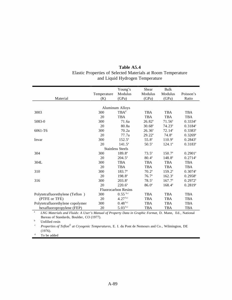
A-89
Table A5.4Elastic Properties of Selected Materials at Room Temperature
and Liquid Hydrogen Temperature
MaterialTemperature
(K)
Young’sModulus(GPa)
ShearModulus
(GPa)
BulkModulus(GPa)
Poisson’sRatio
Aluminum Alloys3003 300
20TBAd
TBATBATBA
TBATBA
TBATBA
5083-0 30020
71.6a80.8a
26.82a
30.68a71.56a
74.23a0.3334a
0.3184a
6061-T6 30020
70.2a77.7a
26.36a
29.22a72.14a
74.8a0.3383a
0.3269a
Invar 30020
152.5a
141.5a55.8a
50.5a110.9a
124.1a0.2843a
0.3183a
Stainless Steels304 300
20189.8a
204.5a73.5a
80.4a150.7a
148.8a0.2901a
0.2714a
304L 30020
TBATBA
TBATBA
TBATBA
TBATBA
310 30020
183.7a
198.8a70.2a
76.7a159.2a
162.3a0.3074a
0.2958a
316 30020
203.8a
220.6a78.5a
86.0a167.7a
168.4a0.2972a
0.2819a
Fluorocarbon ResinsPolytetrafluorethylene (Teflon)
(PTFE or TFE)30020
0.55 b,c
4.27 b,cTBATBA
TBATBA
TBATBA
Polytetrafluorethylene copolymerhexafluoropropylene (FEP)
30020
0.48 b,c
5.03 b,cTBATBA
TBATBA
TBATBA
a LNG Materials and Fluids: A User’s Manual of Property Data in Graphic Format, D. Mann, Ed., NationalBureau of Standards, Boulder, CO (1977).
b Unfilled resinc Properties of Teflon at Cryogenic Temperatures, E. I. du Pont de Nemours and Co., Wilmington, DE
(1976).d To be added

A-90
Table A5.5Mechanical Properties of Selected Materials at Room Temperature
and Liquid Hydrogen Temperature
MaterialTemperature
(K)
YieldStrength(MPa)
TensileStrength(MPa)
FatigueStrengtha
(MPa)Aluminum Alloys
3003-0 30020
40c
69c110c
375cTBAf
TBA5083-0 300
20141c
170c310c
520c235c
283b,c
6061-T6 30020
278c
350c310c
498c200383
Invar 30020
280c
800c510c
1040cTBATBA
Stainless Steels304 300
20520c
900c640c
1730c190c
TBA304L 300
20280c
330c600c
1730c210c
210b,c
310 30020
220c
680c550c
1260c280c
520b,c
316 30020
230c
610c570c
1400cTBATBA
Fluorocarbon ResinsPolytetrafluorethylene (Teflon) (PTFE or TFE)
30020
11.7 d,e
122.7 d,e31.0 d,e
123.4 d,eTBATBA
Polytetrafluorethylene copolymerHexafluoropropylene (FEP)
30020
13.8 d,e
163.4 d,e27.6 d,e
164.1 d,eTBATBA
a Axial fatigue strength at 106 cyclesb At 77 K, not 20 Kc LNG Materials and Fluids: A User’s Manual of Property Data in Graphic Format, D. Mann, Ed.,
National Bureau of Standards, Boulder, Colorado (1977).d Unfilled resine Properties of Teflon at Cryogenic Temperatures, E. I. du Pont de Nemours and Co., Wilmington,
DE (1976).f To be added

A-91
Table A5.6Thermal Properties of Selected Materials at RoomTemperature and Liquid Hydrogen Temperature
MaterialTemperature
(K)
ThermalConductivity[W/(m·K)]
SpecificHeat
[J/(kg K)]
InstantaneousThermal
Expansiona
LinearThermal
Expansionb
Aluminum Alloys3003 300
20175d
58d
902d,f
8.9d,f
23.2x10⁻⁶ d,f
0.2x10⁻⁶ d,f +16x10-5 d,f
-415x10-5 d,f
5083 30020
118d
17.2d
902d,f
8.9d,f
23.2x10⁻⁶ d,f
0.2x10⁻⁶ d,f
+16x10-5 d,f
-415x10-5 d,f
6061 30020
NANA
902d,f
8.9d,f
23.2x10⁻⁶ d,f
0.2x10⁻⁶ d,f +16x10-5 d,f
-415x10-5 d,f
Invar 30020
14d
1.65d
NA11.8d
1.2x10⁻⁶ d
0d
0d
-40x10-5 d
Stainless Steels304 300
2014.7d
2.12d
NA12.7d
15.9x10⁻⁶ d
0.7x10⁻⁶ d +12x10-5 d
-298x10-5 d
304L 30020
14.7d
2.12d
NA11.8d
15.9x10⁻⁶ d
0.5x10⁻⁶ d +12x10-5 d
-298x10-5 d
310 30020
11.5d
1.71d
475d
11.6d
15.9x10⁻⁶ d
0.5x10⁻⁶ d +12x10-5 d
-298x10-5 d
316 30020
14.7d
2.12d
480d
13.7d
15.9x10⁻⁶ d
0.5x10⁻⁶ d +12x10-5 d
-298x10-5 d
Fluorocarbon ResinsPolytetrafluorethylene (Teflon) (PTFE or TFE)
30020
0.25 h
0.13 h1,010c,f
76f
1.5x10⁻⁴e,g
NA0 i
-2,150x10-5 i
Polytetrafluorethylene copolymerhexafluoropropylene (FEP)
30020
0.20 h
0.12 h1,088 h
TBATBAj
TBA0 i
-1,800x10-5 i
a Instantaneous Thermal Expansion = [(1/L)(dL/dT)], with units of “1/K”b Linear Thermal Expansion = [(L - L293)/L293], with units of “m/m”c At 280 K, not 300 Kd LNG Materials and Fluids: A User’s Manual of Property Data in Graphic Format. , D. Mann, Ed., National
Bureau of Standards, Boulder, Colorado (1977).e at 295 K, not 300 Kf A Compendium of the Properties of Materials at Low Temperature (Phase I), Part II: Properties of Solids. ,
V. J. Johnson, Ed., WADD Technical Report 60-56, October (1960).g Reed, R. P., R. E. Schramm, and A. F. Clark. Mechanical, Thermal, and Electrical Properties of Selected
Polymers, Cryogenics. February (1973): pp. 67-82.h Teflon, Cadillac Plastic and Chemical Co., Birmingham, MI, 1980.i Schwartzberg, F. R., S. H. Osgood, and R. G. Herzog. Cryogenic Materials Data Handbook. Air Force
Materials Laboratory, AFML-TDR-64-280, Supplement 4, Vol. II. Wright-Patterson AFB, OH, August(1968).
j To be added

A-92
Table A5.7Typical Characteristics of Hydrogen Embrittlement Types a
Environmental Internal HydrogenHydrogen Hydrogen Reaction
Characteristic Embrittlement Embrittlement Embrittlement
Usual source ofhydrogen
Gaseous hydrogen Processing,electrolysis,corrosion
Gaseous or atomichydrogen from anysource.
Typicalconditions
10-6 to 10-8 Pa H2 gaspressure. Most severenear room temperature.Observed from -100 to700 °C. Gas purity andstrain rate important.
0.1 to 10 ppm average H2
content. Most severe nearroom temperature. Observedfrom -100 to 100 °C. Strainrate is important.
Heat treatment or servicein H2, especially atelevated temperatures.
Test methods forembrittlement
Notched tensile;unnotched tensile, creeprupture; fatigue (low,high cycle); fracturetoughness; disk pressuretest.
Notched tensile delayedfailure; slow strain ratetensile; bend tests; C-rings;torqued bolts.
Visual or metallographicobservation.
Location of crackinitiation
On surface or internal. b Internal crack initiation;incubation (reversible);slow discontinuous growth;and fast fracture.
Usually internal initiationfrom bubbles or flakes.
Rate-controllingembrittlementstep
Adsorption is transferstep; absorption or latticediffusion b is embrittlingstep.
Lattice diffusion to internalstress risers.
Chemical reaction toform hydrides or gasbubbles.
a Gray H. R, “Testing for Hydrogen Environment Embrittlement: Experimental Variables,” Hydrogen Embrittlement Testing,American Society for Testing and Materials, Special Technical Publication, ASTM STP-543, Philadelphia, PA (1974), pp. 133-151.
b Unresolved

A-93
Table A5.8Susceptibility of Materials to Embrittlement in Hydrogen at 10,000 psi and 72 °Fa
Unnotched ductility Strength ratio, H2/He Elongation, % Reduction of Area,
%Material Notchedb Unnotche
dHe H2 He H2
Extremely embrittled18Ni-250 Maraging
Steel0.12 0.68 8.2 0.2 55 2.5
410 Stainless Steel .22 .70 15 1.3 60 121042 Steel (quenched .22 ---- ---- ----- ---- ----
and tempered)17-7 pH Stainless Steel .23 .92 17 1.7 45 2.5Fe-9Ni-4Co-0.20C .24 .86 15 .5 67 15H-11 .25 .57 8.8 0 30 0René 41 .27 .84 21 4.3 29 11Electro-Formed Nickel .31 ---- ---- ---- ---- ----4140 .40 .96 14 2.6 48 9Inconel 718 .46 .93 17 1.5 26 1440C .50 .40 ---- ---- 3.2 0
Severely embrittledTi-6A1-4V (STA) 0.58 ---- ---- ---- ---- ----430F .68 ---- 22 14 64 37Nickel 270 .70 ---- 56 52 89 67A515 .73 ---- 42 29 67 35HY-100 .73 ---- 20 18 76 63A372 (class IV) .74 ---- 20 10 53 181042 (normalized) .75 ---- ---- ---- 59 27A533-B .78 ---- ---- ---- 66 33Ti-6A1-4V (annealed) .79 ---- ---- ---- ---- ----AISI 1020 .79 ---- ---- ---- 68 45HY-50 .80 ---- ---- ---- 70 60Ti-5A1-2.5Sn (ELI) .81 ---- ---- ---- 45 39Armco Iron .86 ---- ---- ---- 83 50
Slightly embrittled304 ELC Stainless Steel 0.87 ---- ---- ---- 78 71305 Stainless Steel 0.89 ---- ---- ---- 78 75Be-Cu Alloy 25 0.93 ---- ---- ---- 72 71Titanium 0.95 ---- ---- ---- 61 61
Negligibly embrittled310 Stainless Steel 0.93 ---- ---- ---- 64 62A286 .97 ---- ---- ---- 44 437075-T73 Aluminum
Alloy.98 ---- ---- ---- 37 35
316 Stainless Steel 1.00 ---- ---- ---- 72 75OFHC Copper 1.00 ---- ---- ---- 94 94NARloy-Zc 1.10 ---- ---- ---- 24 226061-T6 Aluminum
Alloy1.10 ---- ---- ---- 61 66
1100 aluminum 1.40 ---- ---- ---- 93 93a Chandler, W. T. and R. J. Walter. “Testing to Determine the Effect of High Pressure Hydrogen
Environments on the Mechanical Properties of Metals,” in Hydrogen Embrittlement Testing, ASTM

A-94
543, American Society for Testing and Materials, Philadelphia, PA (1974) pp. 170-197.b Stress concentration factor, Kt, = 8.4c Tested in 7000 psi (48.3 MPa) hydrogen
Note: Dashes indicate no information available

A-95
Table A5.9Comparison of Air, Helium, and Hydrogen Exposureon Selected Aluminum, Nickel, and Copper Alloysa-e
Strength, psi DuctilityTest Test Reduction
Alloy Environment Pressure (psi) Yield Ultimate in area (%) Elongation (%)
Aluminum Alloys
2011 Air 14.5 39.0x10³ 49.1x10³ 48 17He 10,000 32.9x10³ 42.9x10³ 57 18H2 10,000 31.9x10³ 42.9x10³ 58 17
2024 Air 14.5 51.9x10³ 70.9x10³ 33 15He 10,000 46.9x10³ 63.9x10³ 36 19H2 10,000 44.9x10³ 61.9x10³ 35 18
6061 Air 14.5 25.9x10³ 33.9x10³ 75 14He 10,000 28.9x10³ 25.9x10³ 82 15H2 10,000 20.0x10³ 26.9x10³ 82 14
6063 Air 14.5 31.0x10³ 34.9x10³ 62 13He 10,000 22.9x10³ 27.9x10³ 83 15H2 10,000 22.9x10³ 29.0x10³ 84 15
Nickel and Nickel Alloys
Nickel He 10,000 26.0x10³ 61.9x10³ 79 57H2 10,000 24.9x10³ 62.9x10³ 54 47
Inconel He 10,000 151x103 186x103 40 25 718 H2 10,000 155x103 186x103 11 9
Inconel Air 14.7 152x103 204x103 45 21 700 He 10,000 149x103 195x103 44 22
H2 10,000 149x103 177x103 14 10
Hastelloy X Air 14.7 46.9 x10³ 99.9x10³ 69 56He 10,000 41.0 x10³ 99.9x10³ 68 59H2 10,000 41.9 x10³ 94.9x10³ 58 55
Copper Alloys
OFHC Air 14.7 13.9x10³ 33.9x10³ 71 44H2 10,000 13.9x10³ 33.1x10³ 71 45
70-30 brass Air 14.7 17.9x10³ 52.9x10³ 70 59H2 10,000 14.9x10³ 50.0x10³ 84 58
Aluminum Air 14.7 32.5x10³ 87.0x10³ 67 48 bronze H2 10,000 30.7x10³ 83.5x10³ 71 49
a Chandler, W. T. and R. J. Walter. “Hydrogen Environment Embrittlement of Metals and Its Control,”Hydrogen Energy, Proceedings of the Hydrogen Miami Energy Conference, T. H. Veziroglu, Ed., PlenumPress, New York (1975): pp. 1057-1058.
b Groenvald, T. D. and A. D. Elcea. “Hydrogen Stress Cracking in Natural Gas Transmission Pipelines,”Hydrogen in Metals, I. M. Bernstein and A. W. Thompson, Eds., ASM (1974).
c Robinson, S. L. Hydrogen Compatibility of Structural Materials for Energy Storage and TransmissionApplications. Sandia National Laboratories, SAND77-8240, June (1977).
d Hoover, W. R., et. al. Hydrogen Compatibility of Structural Materials for Energy Storage andTransmission Applications. Sandia National Laboratories, SAND80-8202, Livermore, CA, February(1980).
e Stuhrke, W. F. and J. L. Carpenter. Fracture Toughness and Testing Data - A Technology Survey.NASA-CR-134752, January, (1975).

A.6 HYDROGEN AND HYDROGEN FIRE DETECTION

A-99
Figure A6.1
Irradiance of Common IR Sources
Source:
Rosen, B., V. H. Dayan, and R. L. Proffitt. “Hydrogen Leak and Fire Detection - ASurvey.” NASA SP-5092, Washington, DC (1970).

A-100
Figure A6.2Atmospheric IR Transmission and H2-Air-Flame Emission
Source:
Rosen, B., V. H. Dayan, and R. L. Proffitt. “Hydrogen Leak and Fire Detection - ASurvey.” NASA SP-5092, Washington, DC (1970).

A-101
Figure A6.3UV/VIS/Near-IR Emissions
Source:
Barnes, H.L. Private communication, NASA Stennis Space Center (1995).
Ultra-Violet
Near-IR
Thermal IRMID-IR
Figure A6.4Flame Components
Note: A larger portion of the flame emits in the thermal infrared than in the ultra violet. Thismeans that a fire looks bigger with a thermal imager that it does with a near-infraredimager.
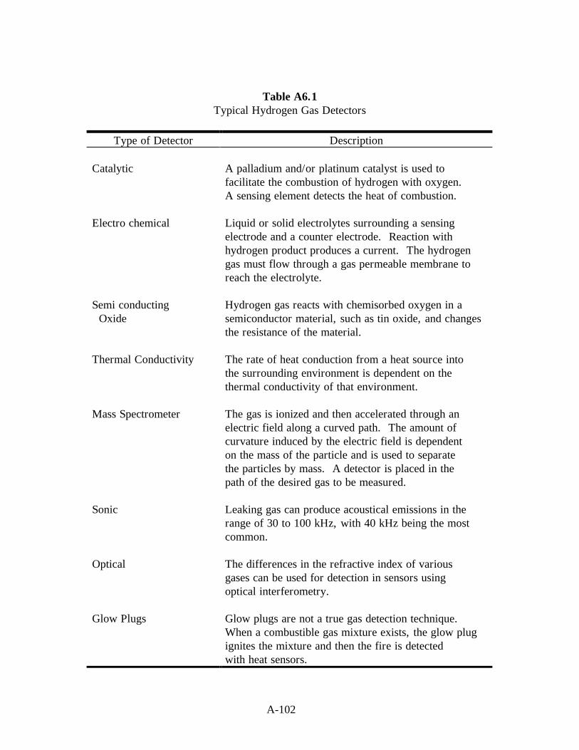
A-102
Table A6.1Typical Hydrogen Gas Detectors
Type of Detector Description
Catalytic A palladium and/or platinum catalyst is used tofacilitate the combustion of hydrogen with oxygen.A sensing element detects the heat of combustion.
Electro chemical Liquid or solid electrolytes surrounding a sensingelectrode and a counter electrode. Reaction withhydrogen product produces a current. The hydrogengas must flow through a gas permeable membrane toreach the electrolyte.
Semi conducting Hydrogen gas reacts with chemisorbed oxygen in a Oxide semiconductor material, such as tin oxide, and changes
the resistance of the material.
Thermal Conductivity The rate of heat conduction from a heat source intothe surrounding environment is dependent on thethermal conductivity of that environment.
Mass Spectrometer The gas is ionized and then accelerated through anelectric field along a curved path. The amount ofcurvature induced by the electric field is dependenton the mass of the particle and is used to separatethe particles by mass. A detector is placed in thepath of the desired gas to be measured.
Sonic Leaking gas can produce acoustical emissions in therange of 30 to 100 kHz, with 40 kHz being the mostcommon.
Optical The differences in the refractive index of variousgases can be used for detection in sensors usingoptical interferometry.
Glow Plugs Glow plugs are not a true gas detection technique.When a combustible gas mixture exists, the glow plugignites the mixture and then the fire is detectedwith heat sensors.

A-103
Table A6.2A Survey and Analysis of Commercially Available Hydrogen Sensors
Conditions
CatalyticCombustionSensors (CC)
Electro chemicalSensors(BC)
Semi conductingOxide Sensors
(SO)
ThermalConductivity
Detectors (TC)D RT PR D RT PR D RT PR D RT PR
In Air293 K/200 ppm + 0 - + + + + + + + 0 +293 K/2% H2 + 0 - + + + + + + + 0 +293 K/100% H2 - - - + + + + + + + 0 +77 K/200 ppm + ? - - - - + ? ? + ? ?77 K/2% H2 + ? - - - - + ? ? + ? ?77 K/100% H2 - - - - - - + ? ? + ? ?
In Helium293 K/200 ppm - - - + + + - - - - - -293 K/2% H2 - - - + + + - - - - - -293 K/100% H2 - - - + + + - - - - - -77 K/200 ppm - - - - - - - - - - - -77 K/2% H2 - - - - - - - - - - - -77 K/100% H2 - - - - - - - - - - - -
In Nitrogen293 K/200 ppm - - - + + + - - - + 0 +293 K/2% H2 - - - + + + - - - + 0 +293 K/100% H2 - - - + + + - - - + 0 +77 K/200 ppm - - - - - - - - - + ? ?77 K/2% H2 - - - - - - - - - + ? ?77 K/100% H2 - - - - - - - - - + ? ?
In Vacuum293 K/200 ppm - - - - - - - - - + 0 +293 K/2% H2 - - - - - - - - - + 0 +293 K/100% H2 - - - - - - - - - + 0 +77 K/200 ppm - - - - - - - - - + ? ?77 K/2% H2 - - - - - - - - - + ? ?77 K/100% H2 - - - - - - - - - + ? ?
Each type of sensor is evaluated for detection, response time, and power requirements according to the following system.Detection (D)(a) Detects (+)(b) Inoperative (-)
? Indicates unknown or not available.
Response time (RT)(a) Less than 3 s (+)(b) Less than 45 s (0)(c) Greater that 45 s (-)
Power requirements (PR)(a) <1 W (+)(b) >1 W (-)
Source:
Hunter, G. W. “A Survey and Analysis of Commercially Available Hydrogen Sensors,”NASA TM-105878, (1992).

A-104
Table A6.3Sensitivity Limits of Hydrogen Detectors
Minimum Detection Limits, Average ValuesIn Air In Nitrogen
Principle atm-cc/s % Hydrogen % LEL atm-cc/s % Hydrogen Distance (ft)
Catalytic Combustion 8.0 0.02 0.5 80 0.2a 2000b
Bubble Testing 1 x 10⁻⁴ NA NA 1 x 10⁻⁴ NA NA
Sonic-Ultrasonic 1 x 10⁻² NA NA 1 x 10⁻² NA 100c
Thermal Conductivity 1 x 10⁻³ 5 x 10⁻⁴ 0.01 1 x 10⁻³ 5 x 10⁻⁴ ----
Gas Density 1 x 10⁻² 5 x 10⁻³ 0.1 1 x 10⁻² 5 x 10⁻³ NA
Hydrogen Tapes 0.25 1.5 35 ---- ---- (d)
Scott-Draeger Tubes ---- 0.5 13 ---- ---- NA
Electrochemical ---- 0.05 1.2 ---- 0.05 1000b
Optical Interferometer ---- 0.2 5 ---- 0.2 NA
a Only one commercial catalytic instrument has claimed to detect hydrogen in nitrogen.b The sensing head is remote from readout.c For pressure differential of 25 psi with orifice of 0.20 inch.d Tape can be placed on suspected leak site and visually checked periodically.
Dashes indicate information is not available.
Source:
Rosen, B., V. H. Dayan, and R. L. Proffitt. “Hydrogen Leak and Fire Detection - ASurvey.” NASA SP-5092, Washington, DC (1970).

A-105
Table A6.4Typical Hydrogen Fire Detectors
Type of Detector Description
Temperature Sensor Thermocouple or resistance temperature device (RTD)that detects the heat of the fire.
Heat Sensitive Cable Wire or fiber-optic based cable that changes resistance oroptical properties if any portion of the cable is exposedto high temperatures or is burned through.
Optical Ultra-violet, mid/near-infrared, and thermal infrareddetectors for the detection of radiation emitted by thehydrogen flame. Infrared detectors must be optimizedfor hydrogen flame emissions that are not the same ashydrocarbon fires.
Broadband Imaging Thermal or mid-infrared imaging systems effectivelyimage hydrogen flames but require an operator tointerpret the image for detection of fire.
Narrow bandImaging
Band-pass filters centered around the 950, 1100, and1400 nm peaks can produce adequate images withlow-cost silicon CCD cameras, image converter tubes,and vidicon systems. The filters must be carefullyselected to block unwanted solar background whileoptimizing the imaging band for atmospherictransmission of the hydrogen fire radiation.
Brooms/Dust Putting flammable objects or dust particles into ahydrogen flame will cause the flame to emit in thevisible spectrum. Corn straw brooms, dirt, and dry fireextinguishers have been used for this purpose.
Source:
Barnes, H. L. Private communication, NASA Stennis Space Center (1994).

A.7 ACCIDENTS INVOLVING HYDROGEN

A-109
Table A7.1Hydrogen Accidents - Industrial
CategoryNumber ofIncidents
Percentage TotalAccidents
Undetected Leaks 32 22Hydrogen-Oxygen Off-gassing Explosions 25 17Piping and Pressure Vessel Ruptures 21 14Inadequate Inert Gas Purging 12 8Vent and Exhaust System Incidents 10 7Hydrogen-Chlorine Incidents 10 7Others 35 25
Total 145 100
Source:
Zalosh, R. G., and T. P. Short. Comparative Analysis of Hydrogen Fires and ExplosionIncidents. C00-4442-2, Factory Mutual Research Corp., Norwood, MA (1978).
Zalosh, R. G., and T. P. Short. Compilation and Analysis of Hydrogen Accident Reports.C00-4442-4, Factory Mutual Research Corp., Norwood, MA (1978).

A-110
Table A7.2Hydrogen Accidents - Ammonia Plants
Classification Number
Gaskets: 46Equipment flanges 23Piping flanges 16Valve flanges 7
Valve packing 10Oil leaks 24Transfer header 9Auxiliary boiler 8Primary reformer 7Cooling tower 3Electrical 2Miscellaneous 16
Source:
Williams, G. P. “Causes of Ammonia Plant Shutdowns.” Chemical Engineering Progress,Vol. 74 (9), (1978).

A-111
Table A7.3Hydrogen Accidents - Aerospace
Accidents Involving Percentage ofDescription Release of Hydrogen Total Accidents
Accidents Iinvolving Release ofLiquid or Gaseous Hydrogen
87 81
Location of Hydrogen Release: To atmosphere 71a 66 To enclosures (piping, 26a 24 containers, etc.)
Ignition of Hydrogen Releases: To atmosphere 44 41 To enclosures 24 22a Hydrogen was released to both locations in 10 accidents.
Source:
Ordin, P. M. “A Review of Hydrogen Accidents and Incidents in NASA Operations,” In 9th
Intersociety Energy Conversion Engineering Conference. New York: ASME, (1974).

A-113
REFERENCES
ASME B31.3. Process Piping. American Society of Mechanical Engineers, New York, NY(1996).
Barnes, H.L. Private communication, NASA Stennis Space Center (1995).
Benz, F. J., C. V. Bishop, and M. D. Pedley. “Ignition and Thermal Hazards of SelectedAerospace Fluids: Overview, Data, and Procedures.” NASA White Sands TestFacility, Las Cruces, NM (1988).
Brown, W. F., Jr., H. Mindlin, and C. Y. Ho, Editors. “Aerospace Structural MetalsHandbook.” CINDAS/USAF CRDA Handbooks Operation, Purdue University,West Lafayette, IN (1996).
Brzustowski, T. A., S R. Gollahalli, and H. F. Sullivan, “The Turbulent Hydrogen DiffusionFlame in a Cross-Wind,” Comb. Sci. Tech., 11(1-2), (1975).
Chandler, W. T. and R. J. Walter, “Testing to Determine the Effect of High PressureHydrogen Environments on the Mechanical Properties of Metals,” in HydrogenEmbrittlement Testing, ASTM 543, American Society for Testing and Materials,Philadelphia, PA (1974): pp. 170-197.
Chandler, W. T., and R. J. Walter. “Hydrogen Environment Embrittlement of Metals and ItsControl,” Hydrogen Energy, Proceedings of the Hydrogen Miami Energy Conference,T. H. Veziroglu, Ed., Plenum Press (1975): pp. 1057-1058.
Coley, G. D. and J. E. Field. “Role of Cavities in the Initiation and Growth of Explosions inLiquids.” Proceedings of the Royal Society of London Series A, 335 (1600), (1973):pp. 67-86.
Coward, H. F. and G. W. Jones. “Limits of Flammability of Gases and Vapors.” Bureau ofMines Bulletin 503, N70-74476; AD-701575 (1952).
Creitz, E. C. “Inhibition of Diffusion Flames by Methyl Bromide and Trifluoromethyl-Bromide Applied to the Fuel and Oxygen Sides of the Reaction Zone.” Journal ofResearch for Applied Physics and Chemistry, 65A (1961): pp. 389-396.
DoD 6055.9. “Ammunition and Explosives Safety Standards.” Department of Defense,(1992).
Durham, T. F., R. M. McClintock, and R. P. Reed. “Cyrogenic Materials Data Handbook.”Office of Technical Services, Washington, DC (1962).

A-114
Gray H. R., “Testing for Hydrogen Environment Embrittlement: Experimental Variables,”Hydrogen Embrittlement Testing, American Society for Testing and Materials, SpecialTechnical Publication, ASTM STP-543, Philadelphia, PA (1974): pp. 133-151
Groenvald, T. D. and A. D. Elcea. “Hydrogen Stress Cracking in Natural Gas TransmissionPipelines,” Hydrogen in Metals, I. M. Bernstein and A. W. Thompson, Eds., ASM(1974).
Grumer, J., A Strasser, J. M. Singer, P. M. Gussey, and V. R. Rowe. “Hydrogen FlareStack Diffusion Flames: Low and High Flow Instabilities, Burning Rates, DilutionLimits, Temperatures, and Wind Effects,” BM-RI-7457, Bureau of Mines Report ofInvestigation (1970).
Hunter, G. W. “A Survey and Analysis of Commercially Available Hydrogen Sensors,”NASA TM-105878, 1992.
Hoover, W. R., et. al. Hydrogen Compatibility of Structural Materials for Energy Storageand Transmission Applications. Sandia National Laboratories, SAND80-8202,Livermore, CA February (1980).
Jones, G. W. and G. St. J. Perrott. “Oxygen Required for the Propagation of Hydrogen,Carbon Monoxide, and Methane Flames”. Ind. Eng. Chem., 19 (9), (1927):pp. 985-989.
Johnson, V. J., Ed. “A Compendium of the Properties of Materials at Low Temperature(Phase I),” WADD Technical Report 60-56, Part II, Properties of Solids, Office ofTechnical Services, United States Department of Commerce, Washington, DC(1960).
Kent, G. R. “Find Radiation Effects of Flares,” Hydrocarbon Processing. 47 (6), (1968):pp. 119-130.
Lee, J. H., R. Kynstantus, C. M. Guirao, W. A. Benedick, and J. E. Shepherd. “Hydrogen-Air Detonations.” Proceedings of the 2nd International Workshop on the Impact ofHydrogen on Water Reactor Safety. M. Berman, Ed., SAND82-2456, SandiaNational Laboratories, Albuquerque, NM, October (1982).
Liebenberg, D. H., J. K. Novak, and F. J. Edeskuty. “Cooldown of Cryogenic TransferSystems.” AIAA 3rd Propulsion Joint Specialist Conference, AIAA Paper No. 67-475, Washington, DC, July 17-21 (1967).
A. D. Little, Inc., “An Investigation of Hazards Associated with the Storage and Handling ofLiquid Hydrogen,” AD 324/94, A. D. Little, Inc., Cambridge, MA, March (1960).
LNG Materials and Fluids: A User’s Manual of Property Data in Graphic Format, D. Mann,Ed., National Bureau of Standards, Boulder, CO (1977).

A-115
McCarty, R. D., J. Hord, and H. M. Roder. Selected Properties of Hydrogen (EngineeringDesign Data). NBS Monograph 168, National Bureau of Standards, Boulder, CO(1981).
McClintock, R. M. and H. P. Gibbons. Mechanical Properties of Structural Materials at LowTemperatures, A Compilation from the Literature. National Bureau of Standards,Monograph 13, United States Department of Commerce, Washington, DC (1960).
McHale, E. T., R. W. Geary, G. von Elbe, and C. Huggett. “Flammability Limits of GH2-GO2-Fluorocarbon Mixtures.” Combustion and Flame, 16 (2), (1971): pp. 167-175.
Mellish, C. E. and J. W. Linnett. “The Influence of Inert Gases on Some FlamePhenomena.” 4th Symposium (International) Combustion, Baltimore, MD (1953):pp. 407-420.
NFPA 50. “Bulk Oxygen Systems at Consumer Sites.” National Fire Protection Association,Inc., Quincy, MA (1990).
NFPA 51. “Design and Installation of Oxygen-Fuel Gas Systems for Welding, Cutting, andAllied Processes.” National Fire Protection Association, Inc., Quincy, MA (1992).
Novak, J. K. “Cooldown Flow Rate Limits Imposed by Thermal Stresses in Liquid Hydrogenor Nitrogen Pipelines.” Advances in Cryogenic Engineering, Vol. 15, K. D.Timmerhaus, Ed., Plenum Press, New York, (1970): pp. 346-353.
NSS 1740.12. “NASA Safety Standard for Explosives, Propellants, and Pyrotechnics.”National Aeronautics and Space Administration, Washington, DC (1993).
Ordin, P. M. “A Review of Hydrogen Accidents and Incidents in NASA Operations,” In 9th
Intersociety Energy Conversion Engineering Conference, New York, ASME, 1974.
Ordin, P. M., and R. C. Carter, “Clinch River Breeder Reactor Hydrogen Disposal andIgnition System,” ARSD-00093, General Electric, June (1980).
Payman, W. and H. Titman. “Limits of Inflammability of Hydrogen and Deuterium inOxygen and Air.” Nature, 137 (1936): pp. 160-168.
Peterson, P. “Explosions in Flare Stacks,” Chem. Eng. Prog., 63(8), August (1967): pp. 67-70.
“Properties of Teflon at Cryogenic Temperatures,” E. I. du Pont de Nemours and Co.,Wilmington, DE (1976).
Reed, R. P., R. E. Schramm, and A. F. Clark. “Mechanical, Thermal, and ElectricalProperties of Selected Polymers,” Cryogenics. February (1973): pp. 67-82.
A-116
Robinson, S. L. “Hydrogen Compatibility of Structural Materials for Energy Storage andTransmission Applications.” Sandia National Laboratories, SAND77-8240, June(1977).
Rosen, B., V. H. Dayan, and R. L. Proffitt. “Hydrogen Leak and Fire Detection - ASurvey.” NASA SP-5092, Washington, DC (1970).
Siegel, R. and J. R. Howell. “Thermal Radiation Heat Transfer. Vol 3: Radiation Transfer withAbsorbing, Emitting, and Scattering Media.” NASA SP-164: Vol. 3 (1971).
Schwartzberg, F. R., S. H. Osgood, and R. G. Herzog. “Cryogenic Materials DataHandbook.” Air Force Materials Laboratory, AFML-TDR-64-280, Supplement 4,Vol. II. Wright-Patterson AFB, OH, August, 1968.
Stuhrke, W. F., and J. L. Carpenter. “Fracture Toughness and Testing Data - A TechnologySurvey.” NASA-CR-134752, January, 1975.
Wigley, D. A. and P. Halford. “Materials of Construction and Techniques of Fabrication.”Cyrogenic Fundamentals, G. G. Haselden, Ed., Chapter 6, Academic Press, London(1971).
Williams, G. P. “Causes of Ammonia Plant Shutdowns.” Chemical Engineering Prog., 74(9), (1978).
Zalosh, R. G. and T. P. Short. “Comparative Analysis of Hydrogen Fires and ExplosionIncidents.” C00-4442-2, Factory Mutual Research Corp., Norwood, MA (1978).
Zalosh, R. G. and T. P. Short. “Compilation and Analysis of Hydrogen Accident Reports.”C00-4442-4, Factory Mutual Research Corp., Norwood, MA (1978).
Zebetakis, M. G. and D. S. Burgess. “Research on the Hazards Associated With theProduction and Handling of Liquid Hydrogen.” BM-RI-5707, Bureau of MinesReport of Investigation, Washington, DC (1961).

B-1
APPENDIX B
ASSESSMENT EXAMPLES
EXAMPLE 1:
Detonation of GH2 with air/oxygen.
STATEMENT OF ASSESSMENT:
The inadvertent introduction of GH2 into a volume containing air-oxygen or the reverseprocess is the source of many of the industrial and aerospace accidents summarized inTables A7.1, A7.2 and A7.3. Hazard analysis requires values for pressures andtemperatures that occur with detonation of the mixture.
System
Hydrogen Oxygen

B-2
SOLUTION:
The Gordon-McBride (1994) program uses Joint Army-Navy-NASA-Air Force(JANNAF) thermodynamic data and performs equilibrium calculations. Table B1shows the computed values for a range of mixtures.
Table B1Detonation Pressures and Temperatures
The T1/T0 and P1/P0 ratios give the temperature and pressure rise across the detonation shock.These are equilibrium (Chapman-Jouguet) values. The examples calculated are for a tenfoldchange in initial pressure (101.3 kPa and 10.1 kPa). The temperature and pressure rise acrossthe detonation shock is similar in relative change.
Volume To a Po
b To Po
% H2 (K) (kPa) T1/To P1/Po (K) (kPa) T1/To P1/Po
Hydrogen/Air
18.3 298 101.3 7.657 12.154 298 10.1 7.580 12.11125 298 101.3 9.257 14.605 298 10.1 8.870 14.22350 298 101.3 8.706 13.713 298 10.1 8.482 13.55559 298 101.3 7.678 12.144 298 10.1 7.601 12.119
Hydrogen/Oxygen
5 298 101.3 3.118 4.880 298 10.1 3.119 4.88225 298 101.3 9.034 14.289 298 10.1 8.660 13.89650 298 101.3 11.646 17.857 298 10.1 10.537 16.61675 298 101.3 12.111 18.671 298 10.1 10.834 17.25090 298 101.3 8.576 13.584 298 10.1 8.327 13.393
a T = temperatureb P = pressure
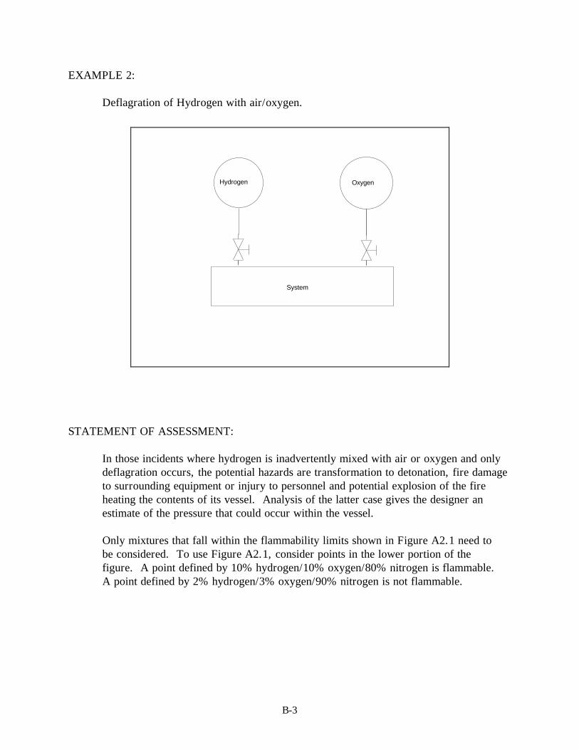
B-3
EXAMPLE 2:
Deflagration of Hydrogen with air/oxygen.
STATEMENT OF ASSESSMENT:
In those incidents where hydrogen is inadvertently mixed with air or oxygen and onlydeflagration occurs, the potential hazards are transformation to detonation, fire damageto surrounding equipment or injury to personnel and potential explosion of the fireheating the contents of its vessel. Analysis of the latter case gives the designer anestimate of the pressure that could occur within the vessel.
Only mixtures that fall within the flammability limits shown in Figure A2.1 need tobe considered. To use Figure A2.1, consider points in the lower portion of thefigure. A point defined by 10% hydrogen/10% oxygen/80% nitrogen is flammable.A point defined by 2% hydrogen/3% oxygen/90% nitrogen is not flammable.
System
Hydrogen Oxygen

B-4
SOLUTION:
The calculation involves a given amount of hydrogen and oxidizer mixed in a specificvolume. The system shown in the schematic is assumed to be 2 m3. B2 gives thetemperature and pressure in the vessel for a range of compositions. The Gordon-McBride (1994) computer code provides the computations. The Gordon-McBride(1994) program uses Joint Army-Navy-NASA-Air Force (JANNAF) thermodynamicdata and performs equilibrium calculations.
Table B2Deflagration Pressures
Volume % To Po Tfa Pf
a To Po Tf Pf
H2 (K) (kPa) (K) (kPa) (K) (kPa) (K) (kPa)
Hydrogen/Air
5 298 101.3 707.9 234.7 273 101.3
684.3 247.6
25 298 101.3 2159.2 643.8 273 101.3
2141.9 697.0
50 298 101.3 1937.9 590.0 273 101.3
1917.7 637.3
75 298 101.3 1165.7 375.6 273 101.3
1142.6 401.9
Hydrogen/Oxygen
5 298 101.3 694.2 230.1 273 101.3
671.6 243.0
25 298 101.3 2134.5 639.1 273 101.3
2118.3 692.2
50 298 101.3 2913.0 808.5 273 101.3
2908.3 880.0
75 298 101.3 3003.4 837.5 273 101.3
2999.2 911.6
90 298 101.3 1899.2 581.4 273 101.3
1878.6 612.2
95 298 101.3 1132.8 365.9 273 101.3
1132.8 399.4
a Tf and Pf are the final temperature and pressure that would occur in the fixed volume (2 m3) when thermodynamicequilibrium occurred.

B-5
EXAMPLE 3:
Calculation of the pressure rise with temperature for both LH2 and SLH2.
STATEMENT OF ASSESSMENT:
The possibility of liquid lockup, the blocking of a section of transfer line completelyfilled (no ullage) with LH2 or SLH2, can be safely avoided with proper design. Shouldsuch a situation occur, the resulting pressures as the system heats can lead to systemdamage or hydrogen leakage. Heating occurs through normal operation because thereis a significant temperature difference between the LH2 or SLH2 and surroundings (atambient). Standard storage system designs usually assume a heat leak equivalent to0.5 percent/day of the liquid contents.
Hydrogen
Liquid or Slush

B-6
SOLUTION:
a. The liquid lockup calculation gives the following pressure increase for thecorresponding temperature increase. The calculation follows:
∂∂
∂∂∂∂
ακ
RT
VTVR
V
R
T
= −
=(Eq. B1)
where:α = the coefficient of thermal expansionκ = is the coefficient of isothermal compressibility (Lewis and Randall
1961).
This can be integrated (assuming constant property values) to obtain thefollowing:
P DT P0= +ακ
(Eq. B2)
At 20.2 K and P0 = 0.101 MPa
α
κ
=
=
−
−
0.01638 K
1
50.4463MPa
1
1
The property values are from McCarty, Hord, and Roder (1981). Results aregiven in Table B3.
Table B3Liquid-Lockup Pressure Change
Given: LH2 at T0 = 15 K∆T (K) ∆P kPa (psia)
0.5 413 (60)1.0 826 (120)5.0 4130 (600)
10.0 8260 (1200)

B-7
b. The pressure rise for SLH2 can occur at constant temperature; the partial molarvolume of solid is less than that of liquid: hence, the melting of solid hydrogenincreases the volume of liquid. The following values for SLH2 and LH2 areobtained from Table A1.1:
density LH2 = 77.03 kg/m3
density SLH2 (50% mass) = 81.50 kg/m3
One cubic meter of 50 percent mass SLH2 contains 81.50 kg; therefore, as LH2
50 percent mass would occupy 1.06 m3. Under a liquid lockup situation, themelting of the solid hydrogen would lead to the formation of increased volume.If no ullage were present the system pressure would rise; however, as thepressure rises, the melting temperature changes (Figure A1.10). The actualsystem pressure would be increasing and if the temperature rose 0.4 K, themelting pressure of the solid would be 1.2 MPa plus the corresponding increasecaused by the change in temperature of the rest of the liquid (part a. of thisexample).
NOTE
Liquid lockup of cryogenic systems is possible if the LH2 is isolated (not readilyhydraulically connected) so pressure increases within the system are notdistributed to a relief valve or burst disc.

B-9
EXAMPLE 4:
Analysis of heat leak on LH2 and ortho-to-para conversion and resulting effects onSLH2 systems.
STATEMENT OF ASSESSMENT:
While LH2 and SLH2 storage systems are designed to minimize heat leaks, there is stilla finite rate at which thermal energy enters the stored material. The value assumedusually is a rate of 0.5 percent of the stored contents per 24 h.
Liquid or Slush Hydrogen
Valve
Pressure
Safety
Volume
Input

B-10
SOLUTION:
a. Assume 100 m3 storage (plus 10 percent ullage) of LH2. What is the pressurerise per day as a result of evaporated liquid? (Neglect effect of pressureincrease on evaporation rate.) Assume LH2 normal hydrogen.
Data: LH2 stored at 20.4 K (normal boiling point) P0 = 101.3 kPa
Amount Evaporated = 0.005⋅100 m3 = 0.5 m3
Mass Evaporated = MVAP = 70.91 kg/m3⋅0.5 m3 = 35.5 kg
Density from Table A1.2 includes:
Moles Evaporated nVAP = 1.760x10⁴ molesInitial moles in ullage (assume ideal gas law applies)
n PVRT0 = (Eq. B3)
n101.3kPa 10m3
101.3kPa 0.0224m3
1mol 273K20.4K
6000moles0 =⋅
⋅⋅
⋅
=
( )P n n RTVf v= +
0
(Eq. B4)
Final pressure:
( ) ( )( )
1760 104 0 6000 104 1013 0 0224
1 27320 4
10 3 400 58
. .. .
.⋅ + ⋅ ⋅⋅
⋅⋅
=
mol KK
mkPa psia
If the compressibility of the hydrogen vapor is considered Z = 0.905(Table A1.2) the final pressure is 362 kPa (52.5 psia).
b. Assume 100 m3 storage (plus 10 percent ullage) of SLH2.
(1) The SLH2 is 50 mass percent solids and assume the solid initially is 80percent para-hydrogen and 20 percent ortho-hydrogen.
(2) Because the equilibrium vapor pressure of SLH2 is 7.20 kPa (Table A1.2),assume the SLH2 is under a blanket of helium to bring the initial pressureto 101.3 kPa.

B-11
(3) The equilibrium temperature of the SLH2 is 13.96 K; therefore, thetemperature difference for heat leak is greater than in the LH2 case and0.5 percent/day rate will assume an appropriate amount of solid-liquidphase change.
Total Initial Mass LH2 = 4075 kgTotal Initial Mass Solid = 4075 kgInitial Mass Para Solid = 3260 kgInitial Mass Ortho Solid = 815 kg
Assume the total thermal energy entering the system by the heat leak isthe same as in part a.
Q = MVAP ⋅ ∆HVAP
(Eq. B5)
Q = 35.5 kg ⋅ 103 g/kg ⋅ 446 J/g = 1.583⋅107 J
Latent Heat of Vaporization from Table A1.1.
Thermal energy from ortho-to-para conversion
∆H CONV = 815 kg ⋅ 103 g/kg ⋅ 525 J/g = 4.279 ⋅ 108 J
Enthalpy of Conversion from Figure A1.2.
Total Solid Melted = ( )1583 10 42 79 10
58 37611
7 7. .
.
⋅ + ⋅= kg (Eq. B6)
Latent Heat of fusion from Table A1.1.
The combined heat leak and ortho-to-para conversion would result in sufficient thermalenergy to melt all the solid because there was originally 4075 kg of solid hydrogen. Thisresult points to the need for lower heat input or continuous regeneration of SLH2. If thisis accomplished, the ortho-to-para conversion could be accomplished external to thestorage vessel and with external regeneration of solid the vessel pressure could bemaintained at its original value. It is also important to note that the equilibrium triplepoint pressure is 7.20 kPa and without the helium blanket the storage vessel would beat negative pressure with respect to ambient.

B-13
EXAMPLE 5:
Amount of solid insulation (not vacuum) required for a specified test line.
Given: 2 in. ID (nominal) line 304 stainless steel pipe. Generally, liquid flowvelocity is less than 10 ft/s and assume heat leak is less than 1/2 percent ofline capacity when in use at steady rate.
Basis: 10 m line; LH2 at 20.3 K. Line is used to transfer 100.0 m3 LH2.
Pipe Dimensions:Length and size 10 m, 2 in. Schedule 40Wall Thickness 3.91 mmInside Diameter 52.50 mmOutside Diameter 60.33 mmInside Cross Section 21.64⋅10-4 m2
Density from Table A1.1 70.78 kg/m3
Total Mass LH2 100.0 m3 ⋅ 70.78 kg/m3 = 7.078⋅103 kgTotal Transferred (with heat leak) 7.078⋅103 kg (1.0 + 0.005) = 7113.4 kg
Total thermal energy leaking into the system. Assume leak only causes phase change.
= (7113.4 - 7078)kg ⋅ 445.6 kJ/kg = 1.577x10⁴ kJ
Liquid Hydrogen
Section of Pipe
Insulation/ / / / / / / / / / / / / / / / / / / / / / / / / / / / / / / / / / / / / / / / / / / / / / / / / / / / / / / / /
/ / / / / / / / / / / / / / / / / / / / / / / / / / / / / / / / / / / / / / / / / / / / / / / / / / / / / / / / /
Pipe Wall
Insulation

B-14
Latent Heat of Vaporization for parahydrogen from Table A1.1 = 445.6 kJ/kg
Length of time to accomplish operation. Assume flow is at 3 m/s (10 ft/s).
Volumetric Flow = 3 m/s ⋅ 21.64⋅10-4 m2 = 6.492⋅10-3 m3/s
Time = 100.0 m3/6.495⋅10-3 m3/s = 1.5396⋅104 s = 4.3 h
Inner Surface Areaof Pipe = π di ⋅ L = π ⋅ 0.05250 m ⋅ 10.0 m = 1.6493 m2
Thermal Flux = 1.577⋅104 kJ/(1.6493 m2 ⋅ 4.3 h) = 0.618 kJ/m2 ⋅s
r i
ro
r1
A i
A1
Ao
Insulation
Pipe

B-15
qSPECIFIED = 1.6493 m2 ⋅ 0.618 kJ/m2⋅s = 1019 W
qCALC = UiAi(TAMB - TLH2)
Ui =1
1
0 0h
xA
k A
yA
k A
A
h Ai
i
x lmx
i
y lmy
i+ + +(Eq. B7)
hi = liquid film transfer coefficient = 552
Wm K⋅
x = pipe wall thickness = 0.00391 m
kx = pipe thermal conductivity = 16 32
.W
m K⋅
Ai = inside pipe surface area = 1.65 m2 (Geankoplis 1983)
Almx = ( )A A
nA
A
Al i
i
i
−
≈
1 0
(Eq. B8)
y = insulation thickness = unknown
ky = insulation (Magnesia, 85%) thermal conductivity = 0.05 Wm K2 ⋅
Almx = A A
nA
A
A A
nA
A
i
l
i
i
0
0
0
01 1
−
≈−
(Eq. B9)
h0 = outside film transfer coefficient = 52
W
m K⋅
A0 = outside area of insulation

B-16
The problem is given q, Tamb, TLH2, and all parameter values solve for r0 → A0
Ui =1
0.0182 0.0002433.0y
lmyA
0.33
0A+ + +
(Eq. B10)
y = r0 - 0.0302 mA0 = 10.0 m ⋅ 2 ⋅ π ⋅ r0
TLH2 = 20.3 KTamb = 298 K
TRIAL-AND-ERROR SOLUTION:
Assume a value for r0, solve for Ui, solve for qCALC
Does qCALC = qSPECIFIED?
Let y = 6 in., therefore, r0 = 0.183 my = 0.152 mA0 = 11.5 m2
Almy = 5.07 m2
Ui = 10 0182 0 00024 0 989 0 029
0 9652. . . .
.+ + +
=⋅
W
m K
qCALC = 0.965(1.65)(298-20.3) = 442 W
qCALC < qSPECIFIED and 6 in. of magnesia insulation would suffice.
Let y = 3 in., therefore, r0 = 0.1064 my = 0.0762 mA0 = 6.68 m2
Almy = 3.6 m2
Ui = 10 0182 0 00024 0 698 0 2. . . .0494
1306+ + +
=⋅
W
m K
qCALC = 1.306(1.65)(298-20.3) = 598 W
qCALC < qSPECIFIED and 3 in. of magnesia insulation would suffice.
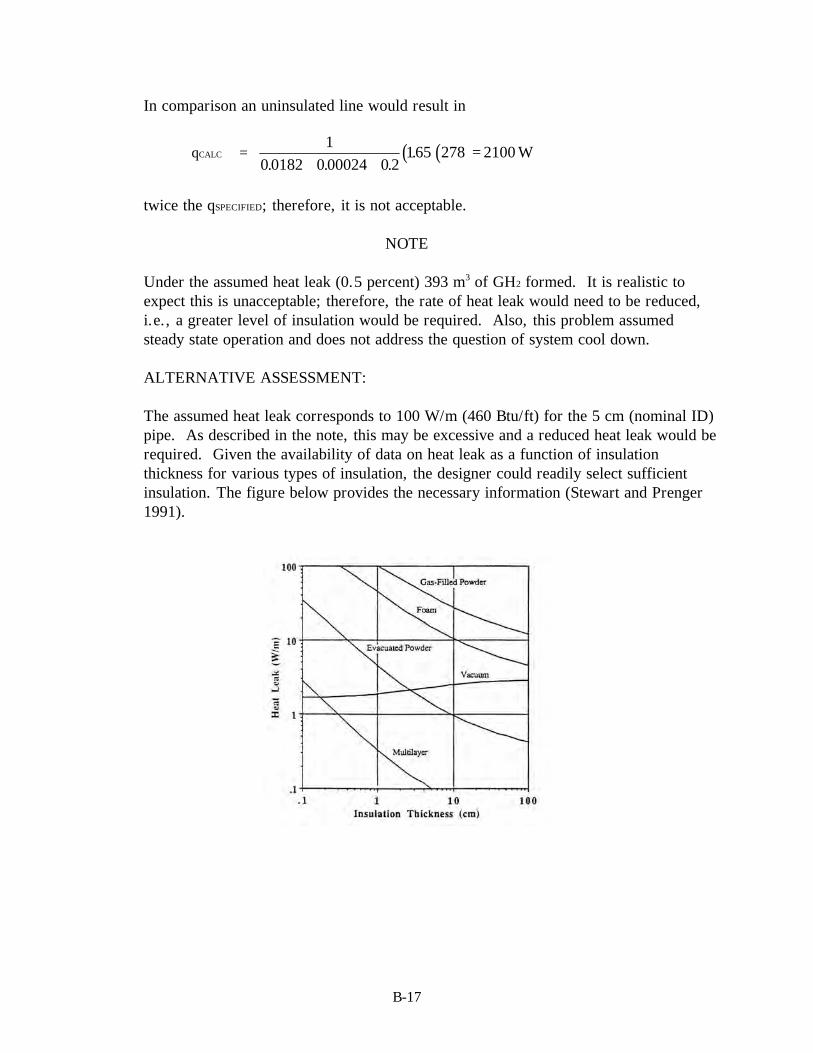
B-17
In comparison an uninsulated line would result in
qCALC = ( )( )10 0182 0 00024 0 2
165 278 2100. . .
.+ +
= W
twice the qSPECIFIED; therefore, it is not acceptable.
NOTE
Under the assumed heat leak (0.5 percent) 393 m3 of GH2 formed. It is realistic toexpect this is unacceptable; therefore, the rate of heat leak would need to be reduced,i.e., a greater level of insulation would be required. Also, this problem assumedsteady state operation and does not address the question of system cool down.
ALTERNATIVE ASSESSMENT:
The assumed heat leak corresponds to 100 W/m (460 Btu/ft) for the 5 cm (nominal ID)pipe. As described in the note, this may be excessive and a reduced heat leak would berequired. Given the availability of data on heat leak as a function of insulationthickness for various types of insulation, the designer could readily select sufficientinsulation. The figure below provides the necessary information (Stewart and Prenger1991).

B-19
EXAMPLE 6:
Calculation for siting an LH2 storage dewar.
Road
Offices
Cell1
Cell2
Cell3
Cell4
Possible Dewar Site
? m
? m
? m
100 m 8 m
8 m
Transfer Line
N
STATEMENT OF ASSESSMENT:
Assume that given the geographical layout shown in the schematic, the problem is tolocate a 1000 gal LH2 dewar to supply experiments conducted in Cell 1 of theschematic.
a. Cell construction is reinforced concrete wall with vented, flat-poured concrete roof.
b. Operation of experimental systems within the cells is controlled remotely from theoffice structure.
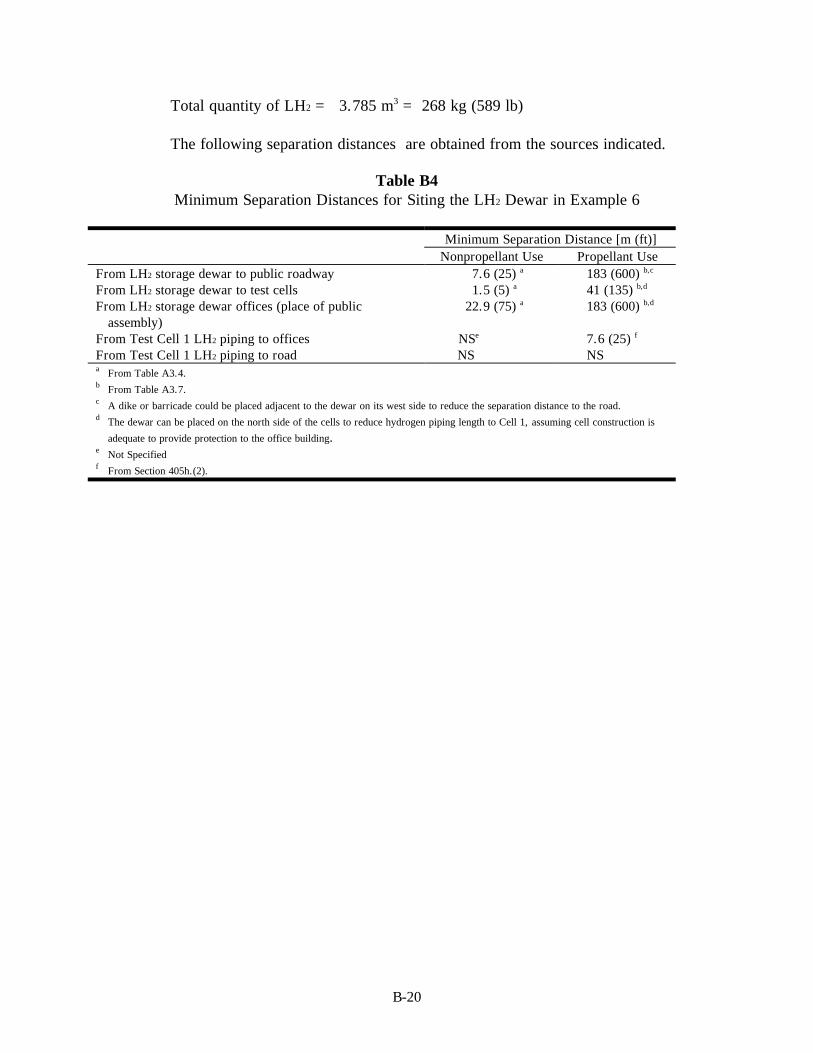
B-20
Total quantity of LH2 = 3.785 m3 = 268 kg (589 lb)
The following separation distances are obtained from the sources indicated.
Table B4Minimum Separation Distances for Siting the LH2 Dewar in Example 6
Minimum Separation Distance [m (ft)]Nonpropellant Use Propellant Use
From LH2 storage dewar to public roadway 7.6 (25) a 183 (600) b,c
From LH2 storage dewar to test cells 1.5 (5) a 41 (135) b,d
From LH2 storage dewar offices (place of publicassembly)
22.9 (75) a 183 (600) b,d
From Test Cell 1 LH2 piping to offices NSe 7.6 (25) f
From Test Cell 1 LH2 piping to road NS NSa From Table A3.4.b From Table A3.7.c A dike or barricade could be placed adjacent to the dewar on its west side to reduce the separation distance to the road.d The dewar can be placed on the north side of the cells to reduce hydrogen piping length to Cell 1, assuming cell construction is
adequate to provide protection to the office building.e Not Specifiedf From Section 405h.(2).

B-21
EXAMPLE 7:
Analysis of a pressure relief valve.
STATEMENT OF ASSESSMENT:
Each system and item of equipment should be examined for operational safety as setforth by specified requirements. Relief capacity is based on the most severerequirement of a system.
Hydrogen
Dewar
Storage
Relief Valve
Vent
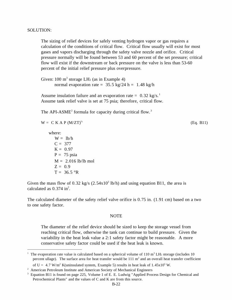
B-22
SOLUTION:
The sizing of relief devices for safely venting hydrogen vapor or gas requires acalculation of the conditions of critical flow. Critical flow usually will exist for mostgases and vapors discharging through the safety valve nozzle and orifice. Criticalpressure normally will be found between 53 and 60 percent of the set pressure; criticalflow will exist if the downstream or back pressure on the valve is less than 53-60percent of the initial relief pressure plus overpressure.
Given: 100 m3 storage LH2 (as in Example 4)normal evaporation rate = 35.5 kg/24 h = 1.48 kg/h
Assume insulation failure and an evaporation rate = 0.32 kg/s.1
Assume tank relief valve is set at 75 psia; therefore, critical flow.
The API-ASME2 formula for capacity during critical flow.3
W = C K A P (M/ZT)½ (Eq. B11)
where:W = lb/hC = 377K = 0.97P = 75 psiaM = 2.016 lb/lb⋅molZ = 0.9T = 36.5 °R
Given the mass flow of 0.32 kg/s (2.54x10³ lb/h) and using equation B11, the area iscalculated as 0.374 in2.
The calculated diameter of the safety relief valve orifice is 0.75 in. (1.91 cm) based on a twoto one safety factor.
NOTE
The diameter of the relief device should be sized to keep the storage vessel fromreaching critical flow, otherwise the tank can continue to build pressure. Given thevariability in the heat leak value a 2:1 safety factor might be reasonable. A moreconservative safety factor could be used if the heat leak is known.
1 The evaporation rate value is calculated based on a spherical volume of 110 m3 LH2 storage (includes 10
percent ullage). The surface area for heat transfer would be 111 m2 and an overall heat transfer coefficient
of U = 4.7 W/m2⋅K(uninsulated system, Example 5) results in heat leak of 1.45x10⁵ W.2 American Petroleum Institute and American Society of Mechanical Engineers3 Equation B11 is found on page 225, Volume 1 of E. E. Ludwig "Applied Process Design for Chemical and
Petrochemical Plants" and the values of C and K are from this source.
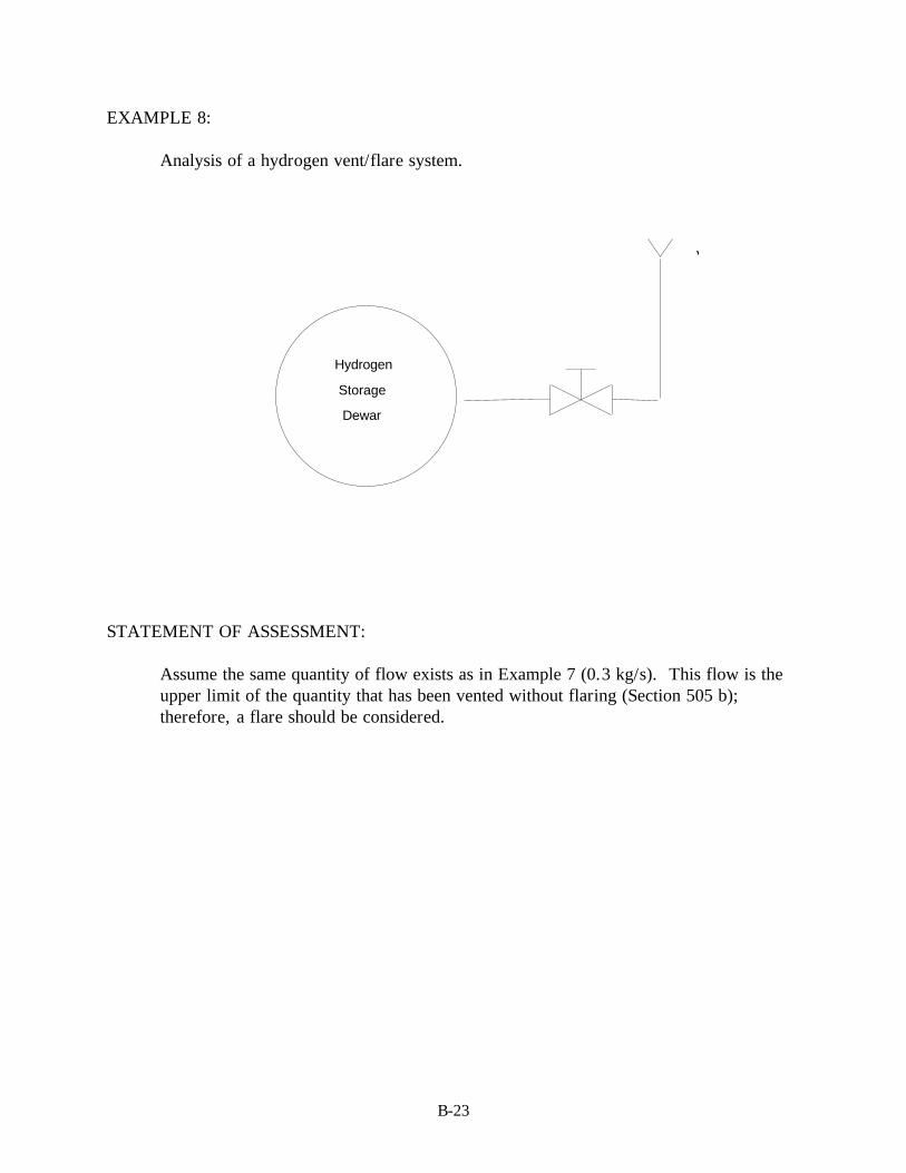
B-23
EXAMPLE 8:
Analysis of a hydrogen vent/flare system.
STATEMENT OF ASSESSMENT:
Assume the same quantity of flow exists as in Example 7 (0.3 kg/s). This flow is theupper limit of the quantity that has been vented without flaring (Section 505 b);therefore, a flare should be considered.
Vent/Flare
Hydrogen
Dewar
Storage

B-24
SOLUTION:
Although Example 7 calculated a 3/4 in. inside diameter relief nozzle, a 24 in. flarestack is used. Figure A4.1 shows that the hydrogen flow rate (0.3 kg/s) and 24 in.stack diameter results in no flame dip. A 24 in. diameter flare stack would be used toget the high concentrations of air (60 to 85 volume percent) without increasing pressuredrop and to limit blowout. The flare flame would still show no flame dip if this werethe case.
Given: 25 percent by volume hydrogen concentration (at 0.3 kg H2/s) the total gasflow would be the following:
H2nn n
0.25; n0.750.25
n
M 0.0289 n 12.9 kg / s
H AIRAIR H
AIR AIR
2
2
+= =
∴ = ⋅ =
vol % = mol %37
at STP velocity at stack exit (24 in. diameter)
=⋅ ⋅
=( . / ) ( . / ) /
./
0 45 2 2 359
3142113
3
2
kgmol s lb mol kgmol ft lbmol
ftft s
According to Figure A4.2, this velocity would result in a stable flame (no blowout);the boundary velocity gradient would be 1356 s-1 using a 1 in. boundary layerthickness.

B-25
EXAMPLE 9:
Analysis of the heat leak into a LH2 or SLH2 transfer line and analysis of the quantityof LH2 consumed to cool the transfer line.
STATEMENT OF ASSESSMENT:
The introduction of LH2 or SLH2 into a system presents the problem of cooling thesystem to the appropriate temperature, 20.3 or 13.8 K. GH2 will be flashed until thesystem approaches these temperatures. Too rapid introduction of the cold fluid cancause large stresses in the piping and vessels of the system.
Two calculations are of interest: 1) the total amount of LH2 or SLH2 needed to cool thesystem and 2) an estimate of the appropriate cooling rate.
Given: 10 m transfer pipe in Example 5.
Mass steel (304L) pipe = ( )p4
d d L 54.24kgo2
i2
P304SS− =
Mass insulation (85% n Magnesia) = ( )p4
d d L 48.06 kg2 2P INSUL− =
5.25 cm
6.033 cm
16.195 cm

B-26
The flow rate of Example 5 is
7.1134 10 kg4.3hr 3600s / h
2.2 lbkg
12 in.
0.505lb
s in.
3⋅⋅
⋅
⋅ =
⋅
Assume the system is to be cooled from 298 to 20.3 K.
CpINSUL = 0.98 kJ/kg⋅KCp304SS = 0.461 kJ/kg⋅Kr304SS = 7817 kg/m3
rINSUL = 271 kg/m3
λLH2 = 899 J/mol = 446 kJ/kg
The total enthalpy change of the system is
( )( )
∆H SSM P SSC dTTT INSULM PINSULC dTT
T
x kJ
= ∫ + ∫
= + − =
304 304 12
12
54 24 0 461 48 06 0 98 298 20 3 2 002 104. * . . * . . .
A mass of LH2 is required (assume phase change only). Note: This calculation wouldbe the maximum required because it does not utilize any of the sensible heat of the GH2
formed (Jacobs 1963).
In changing from 298 to 20.3 K, there is the possibility of a 0.3 percent contraction instainless steel. Figure A4.5 gives the maximum flow rate to avoid too rapid cooling ofpipe.
For given pipe: wall thicknesspipe diameter
0.3925.25
0.075= =
Extrapolation gives a maximum flow rate of 0.1 lb/s⋅in.
In Example 5, at a steady state, the flow rate was 0.5 lb/s⋅in.; therefore, the startup(such as the cool-down period) would need to be at a much lower flow rate (by at leasta factor of 5). In addition, the 44.9 kg of LH2 changed to GH2 would have to behandled by the system if LH2 is used to cool the system. This solution is for nominalpipe thickness. Consideration of the thick wall section of the piping system, such as aflange, would reduce the flow rate because thermal stresses would be greater in thethick wall section.

B-27
EXAMPLE 10:
The purging of hydrogen from systems prior to maintenance or remodeling or thepurging of air from hydrogen storage vessels are important operational procedures.
Given: 100 m3 LH2 (plus 10 percent ullage) storage vessel.
SOLUTION:
a. Total volume : 110 m3
Assume initial volume filled with air at NTP;4 293.3 K and 101.3 kPa(68 °F and 14.7 psia).
Section 701 stipulates that before filling with LH2, the vessel should beevacuated to 1.33 kPa (0.193 psia), repressurized with helium, GN2 or GH2 andvented to atmospheric pressure. Venting must be done safely if GH2 is used.
What is residual oxygen concentration?
Density air = 1.198 kg/m3
Initial moles air = (110 m3⋅1.198 kg/m3)/28.82 kg/kg⋅mol = 4.57 kg⋅mol
Moles air after evacuation (assume ideal gas)
4 Normal temperature and pressure.
Relief
Pressure
Fill
LH2
Discharge
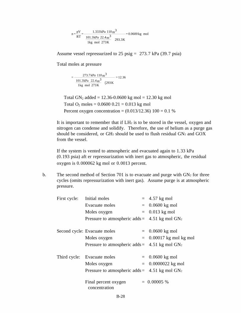
B-28
npV
RT
1.333kPa 110 3m
101.3kPa 22.4 3m1kg mol 273K
293.3K
0.0600kg mol= =⋅
⋅⋅ ⋅
⋅
= ⋅
Assume vessel repressurized to 25 psig = 273.7 kPa (39.7 psia)
Total moles at pressure
( )=
⋅
⋅⋅ ⋅
⋅
=
273.7kPa 110 3m
101.3kPa 22.4 3m1kg mol 273K
293K
12.36
∴ Total GN2 added = 12.36-0.0600 kg⋅mol = 12.30 kg⋅mol∴ Total O2 moles = 0.0600⋅0.21 = 0.013 kg⋅mol∴ Percent oxygen concentration = (0.013/12.36)⋅100 = 0.1 %
It is important to remember that if LH2 is to be stored in the vessel, oxygen andnitrogen can condense and solidify. Therefore, the use of helium as a purge gasshould be considered, or GH2 should be used to flush residual GN2 and GOXfrom the vessel.
If the system is vented to atmospheric and evacuated again to 1.33 kPa(0.193 psia) aft er repressurization with inert gas to atmospheric, the residualoxygen is 0.000062 kg⋅mol or 0.0013 percent.
b. The second method of Section 701 is to evacuate and purge with GN2 for threecycles (omits repressurization with inert gas). Assume purge is at atmosphericpressure.
First cycle: Initial moles = 4.57 kg⋅molEvacuate moles = 0.0600 kg⋅molMoles oxygen = 0.013 kg⋅molPressure to atmospheric adds = 4.51 kg⋅mol GN2
Second cycle: Evacuate moles = 0.0600 kg⋅molMoles oxygen = 0.00017 kg⋅mol kg⋅molPressure to atmospheric adds = 4.51 kg⋅mol GN2
Third cycle: Evacuate moles = 0.0600 kg⋅molMoles oxygen = 0.0000022 kg⋅molPressure to atmospheric adds = 4.51 kg⋅mol GN2
Final percent oxygen = 0.00005 % concentration

B-29
c. The purging of air from new tanks or GH2 vessels for maintenance can be doneusing GN2 or helium until the measured exit concentration is 25 percent of theLFL (at ambient conditions, less than one percent).
Assume the same storage system initially filled with GH2 at 101.3 kPa and293.3 K (68 °F and 14.7 psia).
Density GH2 (from Table A1.1) = 0.0838 kg/m3
Initial moles GH2 = (110 m3⋅0.0838 kg/m3)/2.015 kg/kg⋅mol= 4.57 kg⋅mol
Total moles GN2 to give 1% = 452 kg⋅mol
If added to a single charge (assume constant temperature), final vessel pressurewould equal
Pf = 101.3 kPa (452 + 4.57)/4.57 = 10.1 MPa = 1470 psia
If the vessel cannot contain this pressure, a continuous or semicontinuous batch-type purge must be used.

B-31
EXAMPLE 11:
The accidental leaking or release of hydrogen resulting in flammable mixtures with airpresents a safety issue. The hazard analysis should address whether natural dispersionis sufficient to dissipate the mixture to below the LFL5 or additional operationalrequirements are needed.
SOLUTION:
a. Minimum standard: 400 CF at 70 °F and 14.7 psia. (Section 101b.(2))
Assume GH2 released into 2000 ft3 laboratory space.
Given room ventilation at 2000 cfm6 (air turnover rate equals once per minute).
Case 1: Assume instantaneous release and mixing; therefore, initialvolume concentration in the room = 20 percent GH2
The concentration of GH2 is equal to the following:
( ) ( )n
RT14.7psia
14.7psia 359 3ft
1lb mol 492 R530 R
0.2 0.00052lb mol
3ft0.008
kg mol3m
=⋅
⋅ °⋅ °
⋅ =⋅
=⋅
5 Lower flammability limit.6 Cubic feet per minute
10'
10'
20'

B-32
Mass balance of GH2 in room (in terms of kg⋅mol)
ddt
V C V Crm ⋅ = −•
(Eq. B12)
where:Vrm = volume of roomV = room ventilation rateC = concentration of H2
Co = initial concentration of H2
lnCC
VV
to rm
= −
•
(Eq. B13)
C C expV
Vorm
= −
•
(Eq. B14)
How long does it take to reduce room concentration to less than LFL (4 percent).
tV
V
CC
cfcfm
rm= = −⋅ ln ln0
20002000
420
t = 1.6 min
Assume air turnover rate is once every 4 min ∴ V⋅
= 500 cfm and t = 6.4 minutes. Thesevalues apply only in the case where there is no recirculation of ventilation air.
Case 2: Assuming that leaking GH2 is instantaneously mixed with room air,
what is the maximum leak rate ( N GH
⋅
2 ) that will always result inconcentrations below LFL (4%)?
Mass Balance on GH2 (in terms of kg.mol).
dV C
dtN V C
V
V
dCdt
CN
V
rmGH
rm GH
= −
+ =
• •
•
•
•
2
2
(Eq. B13)

B-33
For V / V = 1 minute @ turnover rate + 2000 cfm, a solution isrm
⋅
( )CN
V1 e
GH2 1= −
•
⋅− (Eq. B14)
at t CN
V
GH2→ ∞ =
•
⋅(Eq. B15)
∴⋅
= − ⋅ = ⋅N GH x kg mol or cfmof GH2 192 10 3 56 63 0109 80 2. . . / min (Eq. B16)
For t C xlb mol
ftor x
kg mol
m0 12 10 4 192 10 3
3< < ∞ < − ⋅ − ⋅
. . (Eq. B17)
b. The example above of instantaneous and complete mixing is the first of twolimiting assumptions. The second limiting assumption is that the hydrogenreleased remains as a pure volume and at a time (t=0), natural dissipationoccurs to reduce the concentration of hydrogen.
Assume a spherical cloud of hydrogen 1 m in diameter at ambient conditions(298 K and 101.3 kPa).
Concentration of Hydrogen in Bubble =
PRT
0.041kg mol
0.003lb mol
3 3m ft= = (Eq. B18)
(1) Assuming equal-molal counter diffusion, such as when the hydrogenleaves the bubble it is replaced by air.
(2) Assume the concentration of hydrogen at the surface of the bubbleremains approximately zero, the solution can be obtained from analyticalsolution of diffusion problems (Carslaw and Jaeger 1959).
Concentration at the center of the bubble
( )CC C n
ne Dn t a= −
=
∞∑ −2 1
10
2 2 2π / (Eq. B19)
where:D = hydrogen diffusivity in air = 0.65 cm2/st = time in secondsa = bubble radius = 50 cm
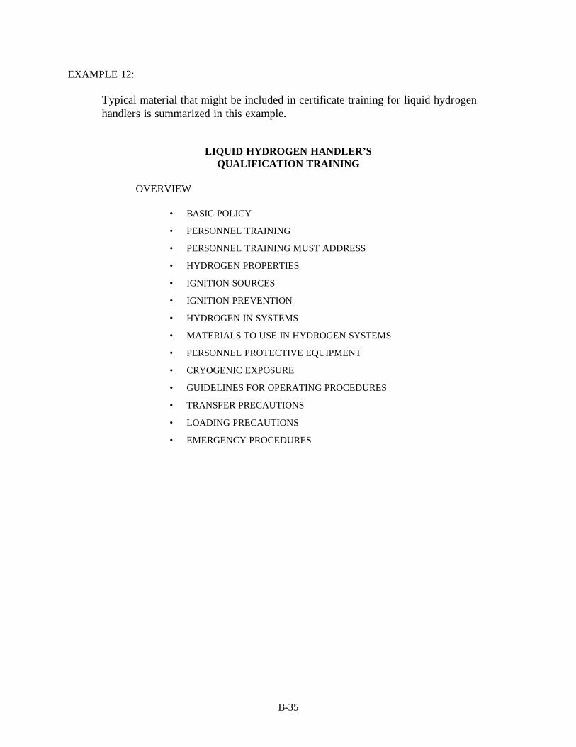
B-35
EXAMPLE 12:
Typical material that might be included in certificate training for liquid hydrogenhandlers is summarized in this example.
LIQUID HYDROGEN HANDLER’SQUALIFICATION TRAINING
OVERVIEW
• BASIC POLICY
• PERSONNEL TRAINING
• PERSONNEL TRAINING MUST ADDRESS
• HYDROGEN PROPERTIES
• IGNITION SOURCES
• IGNITION PREVENTION
• HYDROGEN IN SYSTEMS
• MATERIALS TO USE IN HYDROGEN SYSTEMS
• PERSONNEL PROTECTIVE EQUIPMENT
• CRYOGENIC EXPOSURE
• GUIDELINES FOR OPERATING PROCEDURES
• TRANSFER PRECAUTIONS
• LOADING PRECAUTIONS
• EMERGENCY PROCEDURES

B-36
BASIC POLICY
• Hydrogen can be safely handled like other fuels.
• Safety can be achieved by adherence to the following:
⇒ Prevent hydrogen leaks
⇒ Detect accidental leaks and take proper action
⇒ Prevent hydrogen accumulation
⇒ Remove likely ignition sources and suspect unknown ignition sources
PERSONNEL TRAINING
• Become familiar with hazards of hydrogen
• Recognize human capabilities and limitations
• Become certified for handling LH2/GH2
• Understand EMERGENCY Procedures for leaks and spills
• Adhere to accepted standards, guidelines, and codes for designing hydrogen systems
PERSONNEL TRAINING MUST ADDRESS
• Hazards of hydrogen facilities and operations
⇒ Loading and storage systems
⇒ Purge systems
⇒ Control sampling and analytical systems
⇒ Alarm/warning signal systems
⇒ Ventilation requirements
⇒ Fire and personnel protection
⇒ System schematics and emergency procedures

B-37
HYDROGEN PROPERTIES
• Cryogenic liquids: Boiling point 20 K (-423 °F)
• Liquid density: .07 g/cm3 (water 1 g/cm3)
• Above 23 K (-418.6 °F), lighter than air
• Flammability limits: Air U. 74.8% Oxygen U. 94.0%
• L. 4.1% L. 4.1%
• Detonation limits in Air: 18.3 - 59% hydrogen
• Deflagration 5 to 10 Pi, Detonation ≥ 40 Pi
• Flame temperatures (max.): 2400 K (3865 °F)
• Hydrogen gas can increase in temperature when expanding
IGNITION SOURCES
• Electrical sparks or static electricity (breaking electrical connections, nylon clothing, etc.)
• Friction sparks (metal on metal, stone on stone)
• Impact sparks (sandblasting)
• Autoignition (hot points, etc.) Temperature 584 °C (1084 °F)
IGNITION PREVENTION
• Limit sources (remove flammable items and electrical equipment from the area)
• Inert purge boxes around electrical equipment and connections
• Ground equipment
• Provide lightning protection
• Wear non-sparking clothing
• Spark proof tools

B-38
HYDROGEN IN SYSTEMS
• In LH2 systems, vents and valves can ice up and fail
• Hydrogen systems should be kept at a positive pressure
• Trapped LH2 will evaporate, pressurize and rupture lines
⇒ LH2 at 14.7 psia, heated to 70 °F, has a pressure of 28,000 psia
• Enclosed or partially enclosed storage areas should be well ventilated
MATERIALS TO USE IN LIQUID HYDROGEN SYSTEMS
• Austenitic SS, Aluminum alloys, copper and alloys
• Non-metals: Dacron, Teflon, Kel-F, Mylar, and Nylon
• Effects and causes of hydrogen embrittlement
PERSONNEL PROTECTIVE EQUIPMENT
• The best single investment in safety is trained personnel
• Eye, hand, and non-sparking clothing (face shield, gloves, and cotton coveralls)
• Closed toe, non-porous shoes
CRYOGENIC EXPOSURE
• Cryogenic burns and injuries
⇒ Remove personnel from danger area
⇒ Ensure you are wearing protective equipment (also breathing air, if necessary)
⇒ Call the EMERGENCY CENTER - 5111
• Asphyxiation
⇒ Often occurs in inert H2 purge environments
B-39
GUIDELINES FOR OPERATING PROCEDURES
• Provide control of hazards to an acceptable risk
• Prevention, detection, and course of action for hydrogen leaks
• Adequate ventilation guidelines
• Elimination of ignition hazards
• Outline maintenance procedures, if needed
TRANSFER PRECAUTIONS
• Transfer areas clear of non-essential personnel
• Cancel or discontinue transfers in electrical storms
• Discontinue transfers for leaks or fires
• Isolate, vent, and purge H2 lines before conducting maintenance
• Remove sources of ignition from transfer areas
• Work in a “buddy system”
• Barricades, warning signs, ropes, etc. establish control
LOADING PRECAUTIONS
• Do not overload a vessel, thermal cycling of relief system
• Oxygen content in a vessel <2%
• Ground dewar when receiving shipment
• Watch for condensed water on surfaces/leaks
• No transfers to open mouth dewars/cryopumping
• Cool down storage vessels slowly
• Examine systems for corrosion or blistering

B-40
EMERGENCY PROCEDURES
• Principle danger from a spill or leak is fire
• For H2 fires, isolate source and let burn keeping adjacent metal components cool withwater
• For a LH2 spill, rope off area
• For a leak, isolate source, vent, purge, and repair
• If a vessel is burning near other vessels, the burning vessel may be removed if it can bedone safely
• Do NOT flare leaks deliberately
• If annulus is exposed to air, do NOT cool with water
• If a LH2 vessel overturns, try venting through a liquid outlet if this will allow the ullage tovent

B-41
REFERENCES
Gordon, S. and B. J. McBride. Computer Program for Calculation of Complex ChemicalEquilibrium Compositions and Applications. NASA Reference Publication 1311,October (1994).
Lewis, G. N., and M. Randall. Thermodynamics. Revised by K. S. Pitzer and L Brewer,McGraw-Hill Book Co., Inc., New York (1961).
Ludwig, E. E., "Applied Process Design for Chemical and Petrochemical Plants" and thevalues of C and K are from this source.
Jacobs, R. B. Liquid Requirements for the Cooldown of Cryogenic Equipment. Advances inCryogenic Engineering, Vol. 8, (1963): pp. 529-535.
McCarty, R. D., J. Hord, and H. M. Roder. Selected Properties of Hydrogen (EngineeringDesign Data). NBS Monograph 168, National Bureau of Standards, Boulder, CO(1981).
Geankoplis, C. J. Transport Process and Limit Operations. 2nd Edition, Prentice Hall,Englewood Cliffs, NJ, 1983, pg. 218-219.
Stewart, W. and F. C. Prenger. Thermal Insulation Options for the SuperconductingTransmission Initiative Project. Los Alamos National Laboratory, LA-UR-91-850, LosAlamos, NM (1991).
C-1
APPENDIX C
SCALING LAWS, EXPLOSIONS, BLAST EFFECTS, AND FRAGMENTATION
C.1 SCALING LAWS
A comprehensive review of accidental explosions has been made byStrehlow and Baker (1975). The review characterizes explosions by type,discusses the various scaling laws, and summarizes nonideal blast wavebehavior and the mechanisms by which blast waves produce damage (Stull1977; DoD 6055.9 1992).
a. High explosives or nuclear weapons mainly have been used toproduce the waves in the classical experimental work on blast waves.The intermediate- and far-field waves generally, quite closelyresemble the waves predicted from point-source theory, and to thisextent high explosives or nuclear explosions can be considered ideal.
b. A point-source blast wave is a blast wave conceptually produced bythe instantaneous deposition of a fixed quantity of energy at aninfinitesimal point in a uniform atmosphere. Essentially there arethree regions of interest as a point-source wave propagates awayfrom its source:
1. The near-field wave in which pressures are so large externalpressure (or counter-pressure) can be neglected
2. An intermediate region of extreme practical importancebecause the overpressure and impulse are sufficiently high todo significant damage
3. A far-field region that yields to an analytic approximationsuch that the positive overpressure portion of the curve forlarge distances can easily be constructed from theoverpressure-time curve at one far-field position
c. Scaling the properties of point-source blast waves is common practiceand subject to cube-root scaling (Sach's law). A given pressuretheoretically will occur at a distance from an explosion proportionalto the cube root of the energy yield. Full-scale tests have shown thisrelationship between distance and energy yield to hold over a widerange of explosive weights. According to Sach’s law, if d1 is thedistance from a reference explosion of a mass of W1 at which aspecified hydrostatic overpressure or dynamic pressure is found, for

C-2
any explosion of a mass of W, these same pressures will occur at adistance d given by Equation C1:
d W
d W1 1
1 3
=
/
(Eq. C1)
Plots of overpressures for various explosive weights consequentlycan be superimposed on the curve for 0.45 kg (1 lb) of explosive if,instead of distance, the distance divided by the cube root of theweight is plotted against overpressure. This correlating parameter(d/W)1/3, called scaled distance, is used to simplify the presentationof the blast wave characteristics.
d. Cube-root scaling also can be applied to arrival time of the shockfront, positive-phase duration, and impulse. The distances concernedalso are scaled according to the cube-root law. The relationships canbe expressed in the forms t/t1 = d/d1 = (W/W1)1/3 and I/I1 = d/d1 =(W/W1)1/3, where t1 represents arrival time or positive-phase durationand I1 is the impulse for the reference explosion W1; as before, d1
and d are distances from ground zero. If W1 is taken as 0.45 kg(1 lb), the various quantities are related as t = t1W1/3 at a distance d= d1W1/3 and I = I1W1/3 at a distance d = d1W1/3.
e. No general laws exist for scaling blast waves from nonidealexplosions because not all the physical parameters affecting suchexplosions are known. The general concept of equivalence for anonideal explosion is not well understood. The near-fieldoverpressures usually are much lower than those of a point-sourceexplosion that produces the equivalent far-field overpressure, but it isnot obvious exactly what the relationship between near- and far-fieldbehavior should be or how this relationship differs with the type ofaccidental explosion. It is also not obvious how to evaluate the blastdamage of any particular type of accidental explosion or how muchthe damage depends on the type of explosion.
f. The comparison between ideal and accidental explosions is inexactbecause propellant explosions are not considered point sources. Theconcept of TNT equivalence, widely used in safety studies, is alsovery inexact and may be quite misleading. Scaling laws for nonidealexplosions are not known exactly, but they can be easily developedafter the physics of such explosions is well known. The scaling lawslikely will be variants on Sach's law (Strehlow and Baker 1975;CPIA 1984).
g. Theoretical work suggests that distances at which the pressure levelsare over approximately 101.3 kPa (14.7 psi) for liquid oxygen(LOX)-liquid hydrogen (LH2) explosions, the TNT equivalent interms of peak pressure is about 0.07. The TNT equivalent is about 1
C-3
for pressure levels from 101.3 to 0.7 kPa (14.7 to 0.1 psi); and it isabout 2.0 below 0.7 kPa (0.1 psi).
h. These numbers mean that to generate the same pressure-distancerelationship as 0.45 kg (1 lb) of TNT at 101.3 kPa (14.7 psi) andabove it takes about 6.5 kg (14.3 lb) of LH2 and LOX; from 101.3 to0.7 kPa (14.7 to 0.1 psi), about 0.45 kg (1 lb); and at less than6.9 kPa (0.1 psi) only 0.23 kg (1/2 lb). Correlation with damagingeffects on buildings, vehicles, humans, etc., can be made fromexisting methods and data in the literature if blast wavecharacteristics can be defined for accidental explosions (CPIA 1984;Baker et al. 1978; AMCP-706-180 1972). Fragmentation patternsfrom accidental explosions and the damaging effects of thesefragments are quite difficult to predict.
C.2 TYPES OF EXPLOSIONS
a. Explosions In Buildings.
(1) Explosions in buildings are of three main types, increasing inseverity from type a to type c:
(a) a spill of some combustible material and a slowdeflagration wave or flashback fire causes a relativelyslow buildup of pressure in the building
(b) a piece of equipment explodes and produces a blastwave inside the building that damages the structure oris relieved by venting
(c) a leak occurs, but the combustible mixture that formsdetonates.
(2) The degree of confinement or the bursting pressure of thevessel or building, for the first and second types of explosion,determines the nature of the blast wave generated and damagepatterns. The blast wave behavior and damage patterns in adetonative combustion (third type) primarily are determinedby the behavior of the detonation and are only modified bythe confinement.
b. Tank Ruptures.
(1) A rupture followed by combustion is a very special type ofexplosion that primarily occurs when a tank of liquefied fuel,under pressure, is heated by an external fire, following an

C-4
accident, until the tank vents and torches. The heating of theventing tank needs to be sufficiently intense to cause theinternal pressure to rise above the bursting pressure of thetank for an explosion to occur, even with venting. This typeof explosion has three distinct damage-producing effects:
(a) A blast wave because of internal pressure relief
(b) A fireball caused by subsequent massive burning ofthe tank’s contents in air
(c) Large fragments scattered for long distances becauseof the ductile nature of the rupture of the tank androcketing of pieces by reaction forces
(2) Recent studies show that no single TNT equivalent can beused to describe the blast generated by a rupturing pressurevessel. The tank-rupture blast pressures, combined with thepositive shock wave durations, yield positive values of shockwave impulse with a impulse-distance relationship similar inslope to that for TNT. Impulses for tank rupture and theTNT equivalent are not significantly different quantitativelyfor large, high-pressure vessels.
(3) A general comparison of blast and fragment parametersgenerated by tank rupture and an equivalent TNT chargeshows that side-on pressures are higher for TNT above 69 to41 kPa (10 to 6 psi) and lower for TNT at pressures belowthese values. Face-on tank pressures show a similarrelationship to face-on TNT pressures. Positive shock wavedurations are longer for tank rupture than for TNT. Impulse,face-on and side-on, are similar for TNT and tank rupture.Damage, depending on distance, may be greater for tankrupture. Tank-rupture fragments are larger than would beexpected from a cased TNT charge. Fragment velocities arehigher for a cased TNT charge than for tank rupture (Baker etal. 1974 and 1978).
c. Vapor Cloud Explosions.
1. The visual sequence of events in a vapor cloud explosionfollows:
a) A massive release of a combustible fuel
b) A reasonable delay in ignition, 30 s to 30 min
c) Ignition of the cloud resulting in an explosion

C-5
2. Vapor cloud ignition can lead to two very different types ofbehavior relative to the blast wave produced and leads to theconclusion that detonative combustion needs to always occurbefore a destructive blast wave is produced.
3. Studies using the usual atmospheric dispersion equations haveshown that the maximum fraction of the fuel that would be inthe combustible range at any one time from a continuous ormassive spill would be about 10 percent. This agrees quitesatisfactorily with available data, in which the maximum yieldbased on TNT equivalent weight is about 10 percent (Baker etal. 1974; Strehlow, Savage and Vance 1972). Currentresearch into the behavior of vapor cloud explosions is of twomajor types:
a) Assessing the behavior of a deflagrative explosion ofthe cloud
b) Assessing the area of cloud dispersion
4. The blast waves produced by the explosion of liquidpropellants accidentally mixed generally are quiteunreproducible and difficult to adequately model. Extensivestudies of liquid propellant explosions show that theexplosions differ from TNT explosions in a number of ways,so the concept of TNT equivalence quoted in pounds of TNTis far from exact.
d. Ground-Handling System Explosions.
(1) The hazards from accidental explosions in propellantground-handling systems are similar in many respects to thehazards from such explosions in flight vehicles. Theaccidents cause damage by air-blast loading, fragment orappurtenance impact, radiation from fireballs, or fire from theignition of combustible materials after an explosion (Strehlowand Baker 1975; DoD 6055.9 (1992); CPIA PUB. 394(1984); AMCP-706-180 (1972); Strehlow, Savage, andVance 1972).
(2) Flight and ground systems can fail by material fatigue causedby overstressing. Many possible causes of flight vehicleexplosions; such as loss of thrust during launch, guidancesystem failure, or rupture of a bulkhead separating a fuelfrom an oxidizer; are inapplicable for ground-handlingsystems.

C-6
(3) The nature of the hazards is different becauseground-handling systems have fewer weight constraints thanflight vehicles. The total energy stored in compressed gasesor the total chemical energy stored in fuels and oxidants alsocan be much greater than for many flight systems.
(4) Many more accidental explosions involving fuels andcompressed fluids have occurred in ground-handling systemsthan in flight vehicles, including the following:
(a) Simple pressure vessel failure caused by fatigue orflaw growth
(b) Vessel failure induced by impact during atransportation accident
(c) Vessel failure by overpressure caused by overheating
(d) Vessel and pipeline failure caused by overpressure,corrosion or erosion
(e) Fuel leakage followed by a vapor cloud explosion.
(5) Workbook for Estimating Effects of Accidental Explosions inPropellant Ground Handling and Transport Systems (Baker etal. 1978) and Assembly and Analysis of Fragmentation Datafor Liquid Propellant Vessels (Baker et al. 1974) providemethods for predicting blast and fragment characteristics andeffects for a wide range of possible explosion accidents inground and flight systems. The material allows for theprediction of the following:
(a) Explosive energy yield or energy release
(b) Characteristics of blast pressure waves generated byspherical and nonspherical explosions
(c) Effects of pressure waves on certain classes of targets
(d) Characteristics of fragments generated by groundequipment explosions, including massive vessel partsthat rocket
(e) Effects of fragment impact, including effects offragment revetments on blast waves
Various safety factors are included in the prediction methods.

C-7
C.3 CHARACTERISTICS OF FRAGMENTS
a. Accidental explosions in ground systems tend to produce verydifferent types of fragments or missiles than similar explosions inflight-weight systems. The most striking difference lies in thenumber of fragments generated, usually much fewer for groundsystems than flight systems.
b. Workbook for Estimating Effects of Accidental Explosions inPropellant Ground Handling and Transport Systems (Baker et al.1978) develops methods of predicting velocities and ranges offragments from bursting vessels. The fragment range information isbased on data from various explosion sources.
c. The fragment range and mass distributions for the various explosionsources are also included in the references.
C.4 EFFECTS OF BARRICADES ON BLAST WAVES
a. Barricades are constructed near potential explosion sources or infront of structures and facilities located near potential explosionsources. They are intended to be protective devices to arrestfragments or attenuate blast waves. Results of analyses and testsshow the following:
(1) Barricades reduce peak pressures and impulses behind thebarricades.
(2) Single-revetted barricades are more efficient in reducing peakpressures and impulses than mounds.
(3) Values of peak pressure and impulse are greatly influenced bythe height above the ground, location of the barricade, andbarricade dimensions and configuration.
b. The effects of near-field, single-revetted barricades on peakoverpressures and side-on impulses are given in Workbook forEstimating Effects of Accidental Explosions in Propellant GroundHandling and Transport Systems (Baker et al. 1978) and Principlesof Explosive Behavior (AMCP-706-180 (1972)). The references alsocontain curves indicating blast pressures for predicting lung damageand lethality.
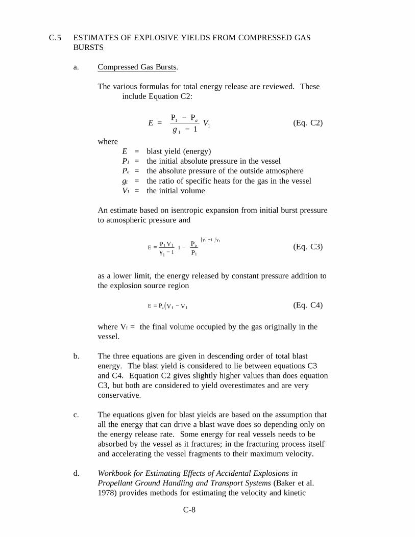
C-8
C.5 ESTIMATES OF EXPLOSIVE YIELDS FROM COMPRESSED GASBURSTS
a. Compressed Gas Bursts.
The various formulas for total energy release are reviewed. Theseinclude Equation C2:
E Va
=
−−
Ρ Ρ1
111γ
(Eq. C2)
whereE = blast yield (energy)P1 = the initial absolute pressure in the vesselPa = the absolute pressure of the outside atmosphereγ1 = the ratio of specific heats for the gas in the vesselV1 = the initial volume
An estimate based on isentropic expansion from initial burst pressureto atmospheric pressure and
( )E
P V a=−
−
−1 1
1 1
1
11
1 1
γ
γ γΡΡ
(Eq. C3)
as a lower limit, the energy released by constant pressure addition tothe explosion source region
( )E a fV V= −Ρ 1 (Eq. C4)
where Vf = the final volume occupied by the gas originally in thevessel.
b. The three equations are given in descending order of total blastenergy. The blast yield is considered to lie between equations C3and C4. Equation C2 gives slightly higher values than does equationC3, but both are considered to yield overestimates and are veryconservative.
c. The equations given for blast yields are based on the assumption thatall the energy that can drive a blast wave does so depending only onthe energy release rate. Some energy for real vessels needs to beabsorbed by the vessel as it fractures; in the fracturing process itselfand accelerating the vessel fragments to their maximum velocity.
d. Workbook for Estimating Effects of Accidental Explosions inPropellant Ground Handling and Transport Systems (Baker et al.1978) provides methods for estimating the velocity and kinetic

C-9
energy of the vessel fragments. Also, the workbook reviews thecharacteristics of blast waves from liquid propellant explosions andspherical gas vessel bursts and their similarities to the differencesfrom waves from condensed high explosives such as TNT.
e. All blast parameters are plotted as nondimensional and are shown asfunctions (fi) of two nondimensional variables P1/Pa and R ,
where R = RP
Ea
1 3
1 3
/
/ and fi is fi
P
PR
a
1 , .
Values of the following properties can be calculated from the scaledcurves:
sP
tt P
a
I aE
s
a
aa a
a a
ss a
a
E
E
=
=
=
=
ΡΡ
ΤΤ Ρ
ΤΡ
1 3
1 3
1 3
1 3
2 3 1 3
/
/
/
/
/ /
(Eq. C5)
where
Pa = ambient pressure (absolute)aa = ambient sound velocityPs = peak static (side-on) overpressureta = arrival time of peak overpressureT = duration of overpressureIs = specific impulseR = radius of blast wave (standoff distance)P1 = internal absolute pressure of sphere
f. Typical blast pressure histories for a burst of a frangible gas sphereare given in Baker et al. (1974) and Adamczyk and Strehlow (1977).Characteristics are a pronounced negative phase compared to the firstpositive phase and the strong second shock wave. By contrast,waves from condensed explosives show much smaller negativephases and seldom have a discernible second shock.
C-10
g. Peak overpressures and shock wave impulse values from a 55 MPagage (8000 psig) and a 4.1 MPa gage (600 psig) tank rupture aregiven in Adamczyk and Strehlow (1977) and Strehlow and Ricker(1976). The term “strength,” used in these references, refers toseveral characteristics of a blast wave that relate to the potential ofthe wave to cause damage and is defined as follows:
(1) Peak overpressure. The static pressure (often called side-onpressure) is greatest at the wave front. This is the peakoverpressure, generally reported as pounds/square inch aboveatmospheric pressure.
(2) Duration. After the wave front passes, the static pressurefalls to slightly below atmospheric. The duration of thepositive phase - the time required to drop the peakoverpressure to atmospheric pressure - is of greatestsignificance in causing damage.
(3) Blast-wind velocity. Behind the front of the blast wave theair moves at considerable speed in the same direction as thewave. A peak overpressure of 34.5 kPa (5 psi) will beaccompanied by a 72 m/s (236 ft/s) wind for example.
(4) Dynamic overpressure. The pressure rise produced when theblast wind is brought to rest is called the dynamicoverpressure.
(5) Peak reflected overpressure. The airflow will be stopped anda shock wave will reflect backward from the surface if a blastwave strikes a surface (such as a wall) at normal incidence.Behind the reflected shock the surface briefly will besubjected to the peak reflected overpressure; sometimes calledthe face-on overpressure. It is considerably larger than thestagnation overpressure; the sum of the peak and dynamicoverpressures.
(6) Positive overpressure impulse. The area under the positivephase of the overpressure time curve at or near the reflectingsurface.
C.6 DEGREES OF HAZARD
a. Hazards with hydrogen may vary depending on the specific location.The hazards are most severe at the range launch pads. The proximityof hydrogen and oxidizers, launchings, nearby facilities, lift-offproblems, and possibilities of fallback make these operations mosthazardous. The liquid propellant explosive equivalent recommended

C-11
is 60 percent; however, the percentage factors should be reducedwhen the propellants are unconfined (CPIA PUB. 394 1984; DoD6055.9 1992; Baker et al. 1978; ).
b. Hazards at static test stands, where heavier tankage and greatercontrols are used, are lower then those at launch pads. Large storagefacilities are not normally involved in feeding the engine during tests.Also, facility design should limit any mixing of propellants, reducingthe hazard potential.
c. Cold-flow test operations in which the fuel and oxidizer havecompletely separate, isolated systems are governed by fire andfragment hazards.
d. Bulk and temporary storage facilities not directly connected to thelaunch and test operations are the least hazardous. Pipelines used fortransferring propellants should be at least 15.2 m (50 ft) from anyinhabited buildings (either side of pipeline).
C.7 ADDITIONAL GUIDELINES
a. Additional guidelines for estimating explosion damage and designs forlimiting explosion damage are presented in Design for LimitingExplosion Damage (Lawrence and Johnson 1974); Guidelines forEstimating Damage Explosion (Brasie and Simpson 1968); Structuresto Resist the Effects of Accidental Explosions (Department of theArmy TM5-1300; and Analysis of Hydrogen Explosion Hazards(Porter 1982).
b. The thermophysical properties of hydrogen are summarized in SelectedProperties of Hydrogen (McCarty, Hord, and Roder 1981).
C-12
C.8 REFERENCES
Adamczyk, A. A., and R. A. Strehlow. Terminal Energy Distribution of Blast Wavesfrom Bursting Spheres. NASA CR-2903 (1973).
Air Force, Army, and Navy. Structures to Resist the Effects of Accidental Explosions.Department of the Army Technical Manual TM5-1300, Department of theNavy Publication NAVFACP-397, Department of the Air Force ManualARM 88-22 (June 1969).
AMCP-706-180. Engineering Design Handbook, Principles of Explosive Behavior.Army Materiel Command, Alexandria, VA, April (1972).
Baker, W. E., J. J. Julesz, R. F. Ricker, P. S. Westine, V. B. Parr, I. M. Vargas,and P. K. Moseley. Workbook for Estimating Effects of AccidentalExplosions in Propellant Ground Handling and Transport Systems. NASACR-3023, NASA (1978).
Baker, W. E., V. Parr, R. Beesey, and D. Cox. Assembly and Analysis ofFragmentation Data for Liquid Propellant Vessels. 74N1562, NASA CR-134538, NASA (1974).
Brasie, W. C., and D. W. Simpson. “Guidelines for Estimating DamageExplosion.” Loss Prevention, Vol. 2, AIChE, (1968): pp. 91-102.
CPIA. “Hazards of Chemical Rockets and Propellants Vol. I, II, and III.”Publication 394, Chemical Propellant Information Agency, The JohnsHopkins University, Applied Physics Laboratory, Laurel, MD (September1984).
DoD 6055.9. Ammunition and Explosives Safety Standards. Department of Defense, July 1992.
Lawrence, W. E., and E. E. Johnson. “Design for Limiting Explosion Damage.”Chemical Engineering, Vol. 81, No. 1 (January 7, 1974): pp. 96-104.
McCarty, R. D., J. Hord, and H. M. Roder. Selected Properties of Hydrogen.NBS-MN-168, National Bureau of Standards (February 1981).
Porter, J. B. Analysis of Hydrogen Explosion Hazards. DP-1295, E. I. DuPontDeNemours, Aiken, SC (July 1982).
Strehlow, R. A., and W. E. Baker. The Characterization and Evaluation ofAccidental Explosions. UILU-ENG-75-0503, NASA Grant NSG-30080,NASA CR-134779, Illinois University, Champaign/Urbana, IL (1975).
Strehlow, R. A., and R. E. Ricker. ”The Blast Wave from a Bursting Sphere.”Loss Prevention, Vol. 10 (1976): pp. 115-121.

C-13
Strehlow, R. A., L. D. Savage, and G. M. Vance. On Measurement of EnergyRelease Rates in Vapor Cloud Explosions. UILU-ENG-72-1503,University of Illinois, Champaign/Urbana, IL, August (1972).
Stull, D. R. “Fundamentals of Fire and Explosion.” AIChE Monograph Series,Vol. 73, No. 10 (1977).
D-1
APPENDIX D
CODES, STANDARDS AND NASA DIRECTIVES
D.1 GENERAL
a. Appendix D gives a brief description and scope of the codes, standards,and NASA directives applicable for hydrogen systems.
b. Standards, such as the ASME Boiler and Pressure Vessel Code (BPVC)(1995) and NFPA 50B (1994), are not mandatory by themselves, butmandatory compliance with various standards can be mandated byfederal, state, or local governments, or by NASA directives.
c. Federal regulations applying to hydrogen are embodied primarily in49 CFR (1995) and 29 CFR (1996), DOT and OSHA, respectively.The DOT portions apply to the transportation of hydrogen, and theOSHA portion applies to its safe handling in the work place. The DOTclassifies and treats gaseous and liquefied hydrogen as a compressed,flammable gas. Hydrogen is classified as a hazardous material in29 CFR (1996).
d. Hydrogen storage is separated into two categories in this guideline:nonpropellant and propellant use.
(1) The nonpropellant category involves the storage of GH2 andLH2 in which the main safety consideration is release andpossible burning of H2 in air. (Section D.4)
(2) The propellant category involves the storage and use of LH2 in
an experimental or test facility or launch complex as a propellantin conjunction with an oxidizer (such as liquid oxygen (LOX)),for which the primary safety consideration is pressure ruptureand/or the rapid combustion, or detonation, of a hydrogen-oxidizer mixture. (Section D.5)
e. There are no NFPA standards specifically for hydrogen pressure pipingas defined in Section D.3c.(4); however, the Compressed GasAssociation has a standard for piping systems described in Section D.3d(CGA G-5.4 1992).
f. The American National Standards Institute (ANSI) is the administratorand coordinator of the United States private sector voluntarystandardization system. ANSI does not itself develop AmericanNational Standards (ANS); rather, it facilitates development by
D-2
establishing consensus among qualified groups. The American Societyof Mechanical Engineers (ASME), and an ANSI document often havethe same designation. The designation for the ANS on Power Pipingcan be listed several ways that include ANSI B31.1, ASME B31.1, andANSI/ASME B31.1. ANSI/ASME B31.1 is the newer, most properdesignation for this standard. A standard developed by an organizationsuch as ASME does not receive an ANSI designation until it has beenapproved as an ANS.
D.2 ASME BOILER AND PRESSURE VESSEL CODE
The ASME BPVC (1986) establishes rules of safety governing the design,fabrication, and inspection of boilers and pressure vessels and nuclear powerplant components during construction. The objective of the rules is to assurereasonably certain protection of life and property and provide a margin fordeterioration in service. Advancements in design and material and the evidenceof experience are constantly being added by Addenda. The BPVC (1996) isorganized in the following sections:
I Power BoilersII Materials
Part A - Ferrous Material SpecificationsPart B - Nonferrous Material SpecificationsPart C - Specifications for Welding Rods, Electrodes and Filler MetalsPart D - Properties
III Rules for Construction of Nuclear Power Plant ComponentsIV Heating BoilersV Nondestructive ExaminationVI Recommended Rules for the Care and Operation of Heating BoilersVII Recommended Guidelines for the Care of Power BoilersVIII Pressure Vessels
Division 1Division 2, Alternative Rules
IX Welding and Brazing QualificationsX Fiber-Reinforced Plastic Pressure VesselsXI Rules for Inservice Inspection of Nuclear Power Plant Components
Section VIII, Division 1 of the BPVC (1996) is commonly specified for thedesign, fabrication, and testing of storage vessels, GH2 and LH2. Section IX ofthe BPVC (1996) is commonly specified for welding.

D-3
D.3 CODES AND STANDARDS FOR PRESSURE PIPING
a. General.
(1) ASME B31, Code for Pressure Piping, sets engineeringrequirements deemed necessary for the safe design andconstruction of pressure piping systems. ASME B31 containsbasic reference data and formulas necessary for design ofpressure piping. It contains prohibitions in areas practices ordesigns are known to be unsafe. The Code contains warnings or“flags” when caution is known to be necessary, but it is felt thata direct prohibition would be unwise. The Code consists of thefollowing sections:
A13.1 Scheme for the Identification of Piping SystemsB31G Manual for Determining the Remaining Strength of
Corroded Pipelines: A Supplement to B31, Code forPressure Piping
B31.1 Power PipingB31.2 Fuel Gas PipingB31.3 Process Piping (formerly Chemical Plant and Petroleum
Refinery Piping)B31.4 Liquid Transportation Systems for Hydrocarbons, Liquid
Petroleum Gas, Anhydrous Ammonia, and AlcoholsB31.5 Refrigeration PipingB31.8 Gas Transmission and Distribution Piping SystemsB31.9 Building Services PipingB31.11Slurry Transportation Piping Systems
Sections A13.1, B31.1, and B31.3 of ASME B31 are the mostapplicable to hydrogen systems.
(2) The development of a code for cryogenic piping (ANSI B31.10)was started, but never completed. Cryogenic pipingwas incorporated into B31.3 rather than having a separate codespecifically for cryogenic piping.
(3) The following specifications are made with regard to the pipingassociated with a GH2 storage system:
NFPA 50A - ASME B31.3, Chemical Plant and Petroleum Refinery Piping
29 CFR 1910.103 - ANSI B31.1-1967 with addenda B31.1-1969, Industrial Gas and Air Piping, Pressure Piping Section 2

D-4
(4) The following specifications are made with regard to the pipingassociated with an LH2 storage vessel:
NFPA 50B - ANSI B31.3, Chemical Plant and Petroleum Refinery Piping, with materials meeting requirements of Chapter III for piping at an operating temperature below 244 K (-20 °F)
29 CFR 1910.103 - ANSI B31.1-1967 with addenda B31.1-1969, Industrial Gas and Air Piping, Pressure Piping Section 2, for GH2 piping at an operating temperature above 244 K(-20 °F)
- ANSI B31.3-1966, Petroleum Refinery Piping or ANSI B31.5-1966 with addenda B31.5a-1968, Refrigeration Piping, for GH2 piping at an operating temperature below 244 K (-20 °F), and for LH2 piping
b. ASME B31.1, Power Piping.
(1) ASME B31.1 (1995) prescribes minimum requirements for thedesign, materials, fabrication, erection, test, and inspection ofpower and auxiliary service piping systems for electricalgeneration stations, industrial and institutional plants, central anddistrict heating plants, and district heating systems except aslimited by the Code. This code covers boiler external piping asdefined in the Code for power boilers and high-temperature,high-pressure water boilers.
(2) Power piping systems covered by this Code apply to all pipingand their component parts within or forming a part of the above-mentioned plants except as excluded in the Code. They includebut are not limited to steam, water, oil, gas, and air services.
(3) This Code does not apply to the following: piping specificallycovered by other Sections of ASME B31 such as fuel gas piping;pressure vessels covered by the BPVC; building heating anddistribution steam piping (low pressure); roof and floor drains,plumbing, sewers, and sprinkler and other fire protectionsystems; piping for hydraulic or pneumatic tools and theircomponents; piping for marine or other installations underFederal control; piping for nuclear installations covered by theBPVC (1986); and building services piping.

D-5
(4) Piping as used in this Code includes pipe, flanges, bolting,gaskets, valves, relief devices, fittings, and pressure containingportions of other piping components. It also includes hangersand supports and other equipment necessary to preventoverstressing the pressure containing components.

D-6
c. ASME B31.3, Process Piping (formerly, “Chemical Plant and PetroleumRefinery Piping”).
(1) ASME B31.3 (1996) prescribes minimum requirements for thedesign, materials, fabrication, erection, test, and inspection ofpressure piping systems for a variety of applications, includingcryogenic plants, petroleum refineries, chemical plants, andrelated processing plants and terminals.
(2) ASME B31.3 (1996) does not cover the piping associated with apressure vessel covered by the ASME BPVC (1995). Pipingassociated with a pressure vessel is covered by the ASMEBPVC (1995), NFPA 50A (1994), NFPA 50B (1994), and 29CFR 1910.103 (1996) for hydrogen. Certain piping within afacility may be subject to other codes and standards, includingbut not limited to the following: piping for fuel gas from thepoint of delivery to the connection of each fuel utilizationdevice; fire protection systems using water, carbon dioxide,Halon, foam, dry and wet chemicals; medical and laboratory gassystems; potable hot and cold water; and sewer and drainsystems.
(3) Piping as used in this guideline includes pipe, tubing, flanges,bolting, gaskets, valves, relief devices, fittings, and the pressurecontaining portions of other piping components. It also includeshangers and supports and other equipment necessary to preventoverstressing pressure containing components.
(4) Piping is considered as the piping that begins when a pressurevessel proper terminates at the following:
(a) The first circumferential joint for welding endconnections
(b) The face of the first flange in bolted flanged connections
(c) The first threaded joint in that type of connection andthat extends up to and includes the valve or valves on thepressure vessel as required by the ASME BPVC (1986).
(5) ASME B31.3 (1996) generally does not specify specificmaterials to be used in piping systems, but provides guidanceand limitations on the selection of some materials acceptable foruse in piping systems. The Code provides some usefulproperties for these materials, such as minimum temperature,

D-7
and maximum allowable stress values as a function of operatingtemperature (see summary in Table A5.3).
d. A standard specifically for hydrogen piping systems is the CompressedGas Association’s “Standard for Hydrogen Piping Systems at ConsumerLocations,” CGA G-5.4 (1992). This CGA standard describes thespecifications and general principles recommended for piping systemsfor gaseous or liquid hydrogen on premises beginning at the point atwhich hydrogen enters the distribution piping (the battery limits of thehydrogen storage system) at service pressure to the use point of thehydrogen. The information in CGA G-5.4 (1992) is general in natureand intended for use by designers, fabricators, installers, users, andmaintainers of hydrogen piping systems and should be of interest tosafety personnel, fire departments, building inspectors, and otheremergency personnel. CGA G-5.4 (1992) specifies piping systemsshould be designed in accordance with ASME B31.3, “Chemical Plantand Petroleum Refinery Piping.”
D.4 STANDARDS AND REGULATIONS FOR THE COMMERCIAL,INDUSTRIAL, AND NONPROPELLANT USE OF HYDROGEN
a. General.
(1) NFPA 50A (1994) and NFPA 50B (1994) have a narrow scopeof application. They cover bulk storage vessels from the pointof fill connection to the point at which hydrogen enters thedistribution piping. They do not cover the delivery vehicle orthe distribution piping. The quantity-distance (QD)requirements are key features of the two standards.
(2) QDs are based on the concept that the effects of fire, explosion,and detonation can be reduced to tolerable levels if the source ofthe hazard is kept far enough from people and other facilities.Having a separation distance between a hydrogen system andpeople and other equipment reduces confinement, whichprovides a greater probability that hydrogen from leaks or spillswill diffuse and dissipate without contacting an ignition source.A separation distance also provides flame-propagation control;thermal radiation from a fire does not create a situation in whichfire from one source is propagated to another combustiblematerial.
(3) NFPA 50A (1994) and NFPA 50B (1994) were developed fromtested and proven industrial handling and storage techniques for

D-8
the practical needs of a commercial operation. (One of theactivities of the NFPA is the development of codes andstandards to enhance fire safety.) Guidelines of the DoD andNASA, such as DoD 6055.9 (1992) and NSS 1740.12 (1993),primarily established for explosives and propellants for missileand rocket applications, were considered in the formulation ofthe NFPA standards for industrial applications. The QDguidelines of the DoD and NASA were considered unrealisticallysevere and did not apply to conventional industrial users. TheNFPA standards were developed on a concept based on themaximum credible accidental leakage or spill that could beexpected in a given installation. Spills of 18.9 to 189L (5 to 50gal) could be expected and would be within the parameters ofthe standard in servicing a typical 26,500 L (7000 gal) LH2
customer station using loading and handling techniquesdeveloped by commercial companies for example. It was feltthat this “reasonable scope of expectation,” based on experience,should be recognized as the safety parameter rather than a majorcatastrophe, such as a falling airplane. The safety philosophy ofthe standard, initially developed as a CGA standard then later asa NFPA standard, may be simply expressed as follows: protectthe system from the user, not just the user from the system. TheNFPA standard specifications for construction, installation,distance locations, and materials were established to limithazards so severe damage to surrounding buildings andpersonnel would be highly unlikely. (Connolly 1967)
(4) NFPA 50A (1994) and NFPA 50B (1994) do not specifywhether the QD guidelines are determined by the hydrogensystem exposing the adjacent occupancy, the adjacent occupancyexposing the hydrogen installation, or a mutual exposure. Adifference in the hazards between the “business” end of a storagevessel and the “nonbusiness” end of a storage vessel is possible.The business end contains the vessel connections, vaporizers,and other equipment. NFPA 50B (1994) addresses thedifference by setting different distances for “insulated” versus“noninsulated” portions of the storage vessel; however, thedistances in NFPA 50A (1994) do not currently reflect anydifference in the hazard between the two ends.1
(5) The QD guidelines of NFPA 50B (1994) are predicated on theinstallation of an emergency vent system sized to prevent astorage vessel rupture even when the vessel is surrounded by fire(NASA TM 104438 1992).
1 Bender, F. X. Presentation notes on discussion of NFPA 50A and NFPA 50B.

D-9
b. NFPA 50A, Gaseous Hydrogen Systems at Consumer Sites.
(1) NFPA 50A (1994) covers the requirements for the installation ofGH2 systems on consumer premises that meet the followingcriteria:
(a) The hydrogen supply to the consumer premisesoriginates outside the consumer premises.
(b) The hydrogen supply is delivered by mobile equipment.
(2) This standard does not apply to single systems using containershaving a total hydrogen content of less than 11 CM (400 CF).However, this standard applies to individual systems, eachhaving a total hydrogen content of less than 11 CM (400 CF)located less than 1.5 m (5 ft) from each other.
(3) This standard does not apply to hydrogen manufacturing plantsor other establishments operated by a hydrogen supplier or thesupplier’s agent for the purpose of storing hydrogen and refillingportable containers, trailers, mobile supply trucks, or tank cars.
(4) The scope, or extent, of the applicability of NFPA 50A (1994) isshown in its definition of a GH2 system. A GH2 system is “onein which the hydrogen is delivered, stored, and discharged in thegaseous form to consumer’s piping. The system includesstationary or movable containers, pressure regulators, pressurerelief devices, manifolds, interconnecting piping, and controls.The system terminates at the point at which hydrogen at servicepressure first enters the consumer’s distribution piping.”
c. NFPA 50B, Liquefied Hydrogen Systems at Consumer Sites.
(1) NFPA 50B (1994) covers the requirements for the installation ofLH2 systems on consumer premises for which the hydrogensupply to the consumer premises originates outside theconsumer premises, and is delivered by mobile equipment.
(2) This standard does not apply to the following:
(a) Portable containers having a total LH2 content of lessthan 150 L (39.7 gal).
(b) LH2 manufacturing plants or other establishmentsoperated by a hydrogen supplier or the supplier’s agent

D-10
for the sole purpose of storing LH2 and refilling portablecontainers, trailers, mobile supply trucks, or tank cars.
(3) The scope, or extent, of the applicability of NFPA 50B (1994) is shownin its definition of a LH2 system. A LH2 system is “a system into whichliquefied hydrogen is delivered and stored and from which it isdischarged in the liquid or gaseous form to consumer piping. Thesystem includes stationary or portable containers, including unconnectedreserves, pressure regulators, pressure relief devices, manifolds,interconnecting piping, and controls as required. The system originatesat the storage container fill connection and terminates at the pointhydrogen at service pressure first enters the supply line.”
d. 29 CFR 1910.103, Hydrogen.
(1) Over time several standards were developed, especially to giveQD recommendations; eventually some of these wereincorporated into the Code of Federal Regulations, and thuscompliance made mandatory. NFPA 50A (1994) and NFPA50B (1994) for GH2 and LH2 storage, were incorporated almostcompletely into 29 CFR 1910.103 (1996) for example.
(2) Part 1910, Occupational Safety and Health Standards, of 29CFR (1996) provides regulations related to safety in the workplace. Subpart H, Hazardous Materials, of 29 CFR 1910 (1996)addresses the safe handling of hazardous materials in theworkplace. An outline of 29 CFR 1910 Subpart H, “HazardousMaterials” (1996), is given below.
1910.101 Compressed gases (general requirements)1910.102 Acetylene1910.103 Hydrogen1910.104 Oxygen1910.105 Nitrous oxide1910.106 Flammable and combustible liquids1910.107 Spray finishing using flammable and combustible
materials1910.108 Dip tanks containing flammable or combustible
liquids1910.109 Explosives and blasting agents1910.110 Storage and handling of liquified petroleum gases1910.111 Storage and handling of anhydrous ammonia1910.112 Reserved1910.113 Reserved1910.114 Effective dates1910.115 Sources of standards

D-11
1910.116 Standards organizations1910.119 Process safety management of highly hazardous
chemicals1910.120 Hazardous waste operations and emergency
response
D.5 DIRECTIVES FOR THE PROPELLANT USE OF LIQUEFIEDHYDROGEN.
a. General.
(1) Two directives that apply to LH2 installations where liquidpropellants are present and cover all types of liquid propellantstorage areas, including missiles, rockets, and multicompartmenttanks in which liquid fuels and liquid oxidizers are stored areNASA NSS 1740.12 (1993) and DoD 6055.9 (1992).
(2) With experimental facilities, especially if LOX or other powerfuloxidizers are present and used in the same experimentalprograms, mechanisms other than those for the nonpropellantuse of hydrogen exist for accidents. Siting concerns includehandling large quantities and high use rates. Hydrogen isincluded in the Group III Hazard Grouping in which the hazardsprimarily are from the pressure rupture of the storage container,deflagration, and vapor phase explosions. Pressure rupture ofthe container or vapor phase explosion can cause a fragmenthazard from the container and its protective structure, or otheradjacent material.
(3) The DoD and NASA guidelines for Bulk Storage (this is themost remote storage with respect to launch and test operations,and never directly connected to any of them) is that fire andfragment hazards govern. The explosive equivalents shall beused to determine QDs if positive measures are not taken toprevent mixing of fuel and oxidizer or to prevent detonationpropagation (NSS 1740.12 1993 and DoD 6055.9 1992).
b. NASA NSS 1740.12, Safety Standard for Explosives, Propellants, andPyrotechnics.
(1) NASA Directive NSS 1740.12 (1993) is based on DoD 6055.9(1992). The QD guidelines in the documents were developed toprotect from fragments, fire, overpressure, and impulsefollowing an explosion, a potential hazard in which the

D-12
probability is increased by the presence of oxidizers or mixedpropellants being used in the same operation. An example of thecalculations for siting an LH2 storage dewar used to provide LH2
to an experimental test cell is given in Appendix B, Example B6.
(2) NSS 1740.12 (1993) is the central Agency document containingpolicy and safety requirements that define the NASA Explosives,Propellant, and Pyrotechnics Safety Program.
(3) NSS 1740.12 (1993) primarily addresses explosives safety;however, some health aspects are included.
(4) NSS 1740.12 (1993) contains the minimum explosives,propellant, and pyrotechnics safety requirements. Additionalexplosive safety publications have been developed for whichinstructions are too detailed for inclusion in NSS 1740.12 (1993)or require special distribution.
(5) NSS 1740.12 (1993) is applicable to all NASA facilities engagedin the development, manufacturing, handling, storage,transportation (on/offsite), processing, or testing of explosives,or assemblies containing explosives. It provides procedures foroperations involving explosives, propellants, and pyrotechnics,and the safe management of such operations.
(6) The propellant section of NSS 1740.12 (1993) applies to storageof liquid propellants in all types of containers, including rocketand tank, in quantities greater than a single shipping containersuch as one 189-L (55-gal) drum or one 227-kg (500-lb)cylinder net weight.
(7) Liquid propellant presents various types and degrees of hazards.Based on these hazards, the following propellant groupings areestablished:
(a) Group I (Fire Hazard)
(b) Group II (Serious Fire Hazard)
(c) Group III (Pressure Rupture, Vapor Phase Explosion,Fragments)
(d) Group IV (Mass Detonating, Severe Fragments)
LH2 is included in Group III. Hazards in this group primarily arefrom pressure rupture of the storage container, resulting from

D-13
fire, deflagration, or vapor-phase explosion. Hazardousfragmentation of the container, its protective structure, or othernearby material may be produced by pressure rupture of thestorage container or a vapor-phase explosion.
(8) The major hazard of the individual propellant can varydepending on the location of the propellant storage andoperations involved. The storage and operations conditions, inorder of decreasing hazards, follow:
(a) Range launch pads
(b) Static test stands
(c) Ready storage
(d) Cold-flow test operations
(e) Bulk storage
(f) Run tankage
(g) Pipelines
(h) Fire and fragment hazards in cold-flow test operationsgovern if the design is such that the system is closed(except for approved venting), is completely airtight, fueland oxidizer are never employed concurrently and eachhas a completely separate isolated system, andpropellants are of the required purity. Otherwise,explosive equivalents must be used to determine QDs.
(i) Bulk storage is the most remote storage with respect tolaunch and test operations, as it is never directlyconnected to any of them. It consists of the area, tanks,and other containers used to hold propellants forsupplying ready storage and, indirectly, run tankagewhen no ready storage is available. Individual bulkstorage facilities must be separated from each other andunrelated exposures. Explosive equivalents must be usedto determine QDs if positive measures are not taken toprevent mixing.
(j) A 7.6-m (25-ft) clear zone to inhabited buildings shall bemaintained on each side of pipelines used for Group II orIII propellants between unloading points and storageareas or between storage areas and points of use.
D-14
(9) Separation distances shall be measured from the closest hazardsource (containers, buildings, segment, or positive cutoff point inpiping, whichever is controlling).
c. DoD 6055.9, DoD Ammunition and Explosives Standards
(1) The purpose of this DoD 6055.9 (1992) is to establish uniformsafety standards applicable to ammunition and explosives,associated personnel and property, and unrelated personnel andproperty exposed to the potential damaging effects of anaccident involving ammunition and explosives during theirdevelopment, manufacturing, testing, transportation, handling,storage, maintenance, demilitarization, and disposal. Thestandards are considered minimum. They apply to DoDammunition and explosives facilities and are designed to provideprotection against serious injury, loss of life, and damage toproperty. The standards address the following subject areas:
(a) Effects of explosives and permissible exposure
(b) Hazard classification and compatibility groups
(c) Personnel protection
(d) Facility construction and siting
(e) Electrical
(f) Lightning protection
(g) Hazard identification for fire fighting
(h) QD
(i) Theater of operations QD
(j) Chemical agents
(k) Real property contaminated with ammunition andexplosives
(l) Mishap reporting and investigation requirements
(2) The damage or injury potential of explosions normally isdetermined by the distance prevailing between the Potential

D-15
Explosion Site (PES) and the Exposed Site (ES); the ability ofthe PES to suppress blast overpressure, primary and secondaryfragments, and debris; and the ability of the ES to resistexplosion effects. The section on liquid propellants setsminimum standards for separating a PES from an ES taking intoaccount explosion effects suppression and resistance anticipated.QD relationships are established for related and unrelated PESsand explosives and nonexplosive ESs.
(3) The section on liquid propellants applies to their storage in alltypes of containers, including rocket and missile tankage, inquantities greater than single minimum size shipping containersuch as one 189 L (55 gal) drum or one 227 kg (500 lb) cylindernet weight. Smaller quantities are to be stored and handled asprescribed by the controlling DoD Component.
(4) These standards are based on the estimated credible damageresulting from an incident, without considering probabilities orfrequency of occurrence.
(5) Quantity of propellant in the associated piping must be includedto the points that positive means are provided for interruptingthe flow through the pipe or interrupting a reaction in the pipe inthe event of an incident.
(6) Separation distances shall be measured from the closest hazardsource (containers, buildings, segment, or positive cutoff point inpiping, whichever is controlling).
(7) A 7.6-m (25-ft) clear zone to inhabited buildings shall bemaintained on each side of pipelines used for Group II or IIIpropellants.
D.6 REGULATIONS FOR TRANSPORTATION EQUIPMENT AND THETRANSPORT OF HYDROGEN
a. Regulations.
Regulations related to transportation equipment and to the transport ofhydrogen are given in 49 CFR, Subtitle B, Chapter I, Subchapters A, B,and C (1995) in the various parts of these subchapters as shown in thefollowing outline.
49 CFR - TransportationSubtitle B - Other Regulations Relating to Transportation

D-16
CHAPTER I - RESEARCH AND SPECIAL PROGRAMSADMINISTRATION, DEPARTMENT OFTRANSPORTATION
SUBCHAPTER A - HAZARDOUSTRANSPORTATION, OILTRANSPORTATION ANDPIPELINE SAFETYPart 100 - [Reserved]Part 106 - Rule making proceduresPart 107 - Hazardous materials
program proceduresPart 110 - Hazardous materials
public sector training andplanning grants
SUBCHAPTER B - OIL TRANSPORTATIONPart 130 - Oil spill prevention and
response plansSUBCHAPTER C - HAZARDOUS MATERIALS
REGULATIONSPart 171 - General information,
regulations, anddefinitions
Part 172 - Hazardous materialstables and hazardousmaterials communicationsregulations
Part 173 - Shippers-generalrequirements forshipments and packagings
Part 174 - Carriage by railPart 175 - Carriage by aircraftPart 176 - Carriage by vesselPart 177 - Carriage by public
highwayPart 178 - Specifications for
packagingsPart 179 - Specifications for tank
carsPart 180 - Continuing qualifications
and maintenance ofpackagings
b. Scope of Subchapter C.
Subchapter C prescribes the requirements of the DOT governing thefollowing:

D-17
(1) The transportation of hazardous materials by, and their offeringto the following:
(a) Carriers by rail car, aircraft, and vessel (water craft suchas ship, ferry, and barge)
(b) Interstate and foreign carriers by motor vehicle
(c) Intrastate carriers by motor vehicle so far as SubchapterC relates to the following
1 Hazardous waste
2 Hazardous substances
3 Flammable cryogenic liquids in portable tanksand cargo tanks
4 Marine pollutants
(2) The manufacture, fabrication, marking, maintenance,reconditioning, repairing, or testing of a packaging or containerrepresented, marked, certified, or sold for use in suchtransportation as described above
(3) Any person who, under contract with any department, agency,or instrumentality of the executive, legislative, or judicial branchof the Federal Government, transports, or causes to betransported or shipped, a hazardous material or manufacturers,fabricates, marks, maintains, reconditions, repairs, or tests apackage or container represented, marked, certified, or sold bysuch person as qualified for use in the transportation ofhazardous materials
c. Hazard Classification for GH2 and LH2.
Compressed and liquefied hydrogen are designated as a Hazard class, orDivision, of 2.1 (Flammable Gas) in 49 CFR 172.101 (1995) and49 CFR 173.2 (1995).

D-18
Table D1 (continued)Selection of Federal Regulations for Hydrogen Transportation
49 CFRPart No. Description
General Requirements for Shipments and Packaging
173.11 Shipper’s registration statement; flammable cryogenic liquids173.31 Qualification, maintenance, and use of tank cars173.33 Hazardous materials in cargo tank motor vehicles173.34 Qualification, maintenance and use of cylinders (hydrogen-specific
requirements listed)173.115 Class 2, Divisions 2.1, 2.2, & 2.3-Definitions (hydrogen is designated as
2.1)173.301 General requirements for shipment of compressed gases in cylinders
(hydrogen-specific requirements listed)173.302 Charging of cylinders with nonliquefied compressed gases (hydrogen-
specific requirements listed)173.314 Requirements for compressed gases in tank cars; (hydrogen-specific
requirements listed)173.315 Compressed gases in cargo tanks and portable tanks173.316 Cryogenic liquids in cylinders (hydrogen-specific requirements listed)173.318 Cryogenic liquids in cargo tanks (hydrogen-specific requirements
listed)173.319 Cryogenic liquids in tank cars (hydrogen-specific requirements listed)173.320 Cryogenic liquids; exceptions177.822 Acceptable articles177.823 Marking and placarding motor vehicles177.824 Retesting and inspection of cargo tanks177.826 Carrier’s registration statement; flammable cryogenic liquids (includes
Division 2.1 materials)
Rail Transportation
172.101 Purpose and use of hazardous materials table (GH2 and LH2 areforbidden on passenger rail service)
173.11 Shipper’s registration statement; flammable cryogenic liquids173.31 Qualification, maintenance, and use of tank cars173.302 Charging of cylinders with nonliquefied compressed gases (hydrogen-
specific requirements listed)173.314 Requirements for compressed gases in tank cars; (hydrogen-specific
requirements listed)173.319 Cryogenic liquids in tank cars (hydrogen-specific requirements listed)

D-19
Table D1 (continued)Selection of Federal Regulations for Hydrogen Transportation
49 CFRPart No. Description
Rail Transportation (continued)
174 Carriage by Rail174.200 Special handling requirements (Division 2.1 materials)174.201 Class 2 (gases) material cylinders174.204 Tank car delivery of gases, including cryogenic liquids179 Specifications for Tank Cars179.10 Tank mounting179.13 Tank car capacity and gross weight limitation179.400 General specifications applicable to cryogenic liquid tank cars (includes
DOT-113A60W tank cars for transport of LH2)179.401 Individual specification requirements applicable to inner tanks for
cryogenic liquid tank car tanks (hydrogen-specific requirements)179.500 Specification DOT-107A * * * * seamless steel tank car tanks
Aircraft Transportation
172.101 GH2 forbidden on passenger aircraft; 150 kg max. permitted on cargoaircraftLH2 forbidden on passenger or cargo aircraft
173.27 General requirements for transportation by aircraft173.302 Charging of cylinders with nonliquefied compressed gases (hydrogen-
specific requirements listed)173.320 Cryogenic liquids; exceptions175 Carriage by Aircraft
Vessel (Watercraft) Transportation
172.101 Purpose and use of hazardous materials table (GH2 forbidden onpassenger vessels; must be stowed “on deck” or “under deck on a cargovessel LH2 forbidden on passenger vessels; must be stowed “on deck”on a cargo vessel)
172.101 & GH2 and LH2 must be stowed “clear of living quarters” and GH2 must176.84 be stowed “separate from” chlorine173.11 Shipper’s registration statement; flammable cryogenic liquids173.318 Cryogenic liquids in cargo tanks (hydrogen specific requirements listed)176 Carriage by Vessel

D-20
Table D1 (continued)Selection of Federal Regulations for Hydrogen Transportation
49 CFRPart No. Description
Vessel (Watercraft) Transportation (continued)
176.76 Transport vehicles, freight containers, and portable tanks containinghazardous materials
176.83 Segregation (Division 2.1 materials included)176.84 Other requirements for storage and segregation for cargo vessels and
passenger vessels (hydrogen specific requirements listed)176.200 General storage requirements (for compressed gases)176.205 Under deck stowage requirements (for compressed gases, including
Division 2.1 materials)176.210 On deck stowage requirements (for compressed gases)176.220 Smoking or open flame and posting of warning signs176.230 Stowage of Division 2.1 (flammable gases) materials
Public Highway Transport
173.11 Shipper’s registration statement; flammable cryogenic liquids173.33 Hazardous materials in cargo tank motor vehicles173.34 Qualification, maintenance and use of cylinders (hydrogen-specific
requirements listed)173.302 Charging of cylinders with nonliquefied compressed gases (hydrogen-
specific requirements listed)173.314 Requirements for compressed gases in tank cars (hydrogen specific
requirements listed)173.315 Compressed gases in cargo tanks and portable tanks173.316 Cryogenic liquids in cylinders (hydrogen-specific requirements listed)173.318 Cryogenic liquids in cargo tanks (hydrogen-specific requirements
listed)177 Carriage by Public Highway177.816 Driver training177.818 Special instructions; Division 2.1 (flammable gas) materials that are
cryogenic liquids177.822 Acceptable articles177.823 Marking and placarding motor vehicles177.824 Retesting and inspection of cargo tanks177.826 Carrier’s registration statement; flammable cryogenic liquids (includes
Division 2.1 materials)

D-21
177.834 General requirements (Loading and Unloading) (includes Class 2(gases) and Division 2.1 (flammable gas` materials)

D-22
Table D1 (continued)Selection of Federal Regulations for Hydrogen Transportation
49 CFRPart No. Description
Public Highway Transport (continued)
177.840 Class 2 (gases) materials (includes Division 2.1 materials; hydrogen-specific requirements listed)
177.848 Segregation of hazardous materials177.853 Transportation and delivery of shipments (includes Class 2 (gases) and
Division 2.1 materials)177.859 Accidents; Class 2 (gases) materials (includes Division 2.1 materials)178.57 Specification 4L; welded cylinders insulated (LH2 may be shipped in a
DOT-4L cylinder)
Packagings
178.3 Marking of packagings178.37 Specification 3AA; seamless steel cylinders made of definitely
prescribed steels or 3AAAX; seamless steel cylinders made of definitelyprescribed steels of capacity of over 1,000 pounds water volume
178.57 Specification 4L; welded cylinders insulated (LH2 may be shipped in aDOT-4L cylinder)
178.320 General requirements applicable to all DOT specification cargo tankmotor vehicles
178.337 Specification MC 331; cargo tank motor vehicle primarily fortransportation of compressed gases as defined in Subpart G of Part 173of this subchapter
178.338 Specification MC-338; insulated cargo tank178 Appendix A - Specifications for Steel178 Appendix B - Alternative Leakproofness Test Methods180 Continuing Qualification and Maintenance of Packagings

D-23
D.7 REFERENCES
ANSI/ASME B31.3. Process Piping. American Society of Mechanical Engineers,New York, NY (1996).
ASME. ASME Boiler and Pressure Vessel Code, Section V, NondestructiveExamination. American Society of Mechanical Engineers, New York, NY(1995).
ASME. ASME Boiler and Pressure Vessel Code, Section VIII, Rules for Constructionof Pressure Vessels, Division 1. American Society of Mechanical Engineers,New York, NY (1995).
ASME. ASME Boiler and Pressure Vessel Code, Section IX, Welding and BrazingQualifications Procedures. American Society of Mechanical Engineers, NewYork, NY (1995).
Bender, F. X., Private Communication.
CFR Title 29. Occupational Health and Safety Standards. Code of FederalRegulations. Parts 1900 to 1910, U.S. Government Printing Office,Washington, 1993.
CFR Title 49. Transportation. Code of Federal Regulations. Parts 106-180, Spring1994 Edition, GSI Computer Services, Branson, MO
CGA G-5.4. Standard for Hydrogen Piping Systems at Consumer Locations.Compressed Gas Association. Arlington, VA (1992).
Connolly, W. W., “A Practical Safety Standard for Commercial Handling of LiquefiedHydrogen,” in Advances in Cryogenic Engineering, Vol. 12, Plenum Press,New York, 1967.
DoD 6055.9. Ammunition and Explosives Safety Standards. Department of Defense,1992.
NASA TM 104438, Lewis Safety Manual, Chapter 6, Hydrogen Propellant, 1992.
NFPA 50A. Standard for Gaseous Hydrogen Systems at Consumer Sites. NationalFire Protection Association, Inc., Quincy, MA (1994).
NFPA 50B. Standard for Liquefied Hydrogen Systems at Consumer Sites. NationalFire Protection Association, Inc., Quincy, MA (1994).
NSS 1740.12. NASA Safety Standard for Explosives, Propellants, and Pyrotechnics.National Aeronautics and Space Administration, Washington, DC (1993).
E-1
APPENDIX E
RELIEF DEVICES
E.1 GENERAL
a. The nomenclature used in discussing relief devices is defined asfollows:
(1) Operating pressure. The pressure at which a piping system isto be used on a steady-state basis. It may range from avacuum to the design pressure. Special consideration should begiven to the relief device choice to prevent simmer(preopening leakage) if a pressure higher than 90 percent ofdesign is used.
(2) Set pressure. The pressure at which a protective device is setto discharge.
(3) Maximum Allowable Working Pressure (MAWP). Themaxiumu pressure permissible at the top of a vessel in itsnormal operating position at the coincident operatingtemperature. It is the least of the values found based oncalculations for every element of the vessel using nominalthickness exclusive of any allowances for corrosion orloadings other than pressure, and adjusted for any defferencefor static head that may exist between the part considered andthe top of the vessel.
(4) Design Pressure. The pressure used in the design of a vesselfor the purpose of determining the minimum requiredthickness of the components of the vessel. When applicable,static head shall be added to the design pressure.
(5) Protective device. A generic term for any device designed tolimit the pressure in a piping system.
(6) Safety device. An automatic protective device actuated by thestatic pressure upstream of the device and characterized by fullopening pop action.
(7) Relief device. An automatic, reseatable protective deviceactuated by the static pressure upstream of the device and forwhich the opening is proportional to the increase in pressureover the opening pressure.

E-2
(8) Safety relief device. A protective device combining thefunctions of a safety device and relief device, usually beingproportional during the first part of its stroke and having popaction during the last part.
(9) System relief device. A protective device designed to thesystem pressure. This device should be set at or below thedesign pressure and should prevent the pressure from risingmore than 10 percent above the design pressure.
(10) Isolation protective device. A protective device required oneach isolatable piping section not directly connected to anyexternal pressure source and for which the only pressuresource when isolated is the nominal heat leak into the line. Itshould be set to open on a pressure no greater than 125percent of the design pressure or 85 percent of the testpressure, whichever is lower. It should be sized to prevent thepressure from rising no more than 10 percent above theselimits.
(11) Supplemental protective device. A protective device installedto protect against excessive pressure from abnormal sources orconditions. This device should be capable of preventing thepressure from rising above the test pressure. Its set pressureshould not exceed 85 percent of the test pressure. It may be asafety or relief device.
b. Pressure-relief devices should be applied to all systems having apressure source that can exceed the maximum allowable pressure ofthe system or for which the malfunction or failure of any componentcan cause the maximum allowable pressure to be exceeded. Reliefdevices are required downstream of all regulating valves and orificesunless the downstream system is designed to accept full sourcepressure. The protection provided by the ground pressurizationsystem should be considered satisfactory when spacecraft operationalor weight limitations preclude the use of relief valves and the systemsoperate in an environment not hazardous to personnel (unmannedspacecraft) only if that protection cannot be isolated from thespacecraft.
c. All pressure-relief devices should be sized and tested in accordancewith the capacities of the pressure source and provide initial relief atthe maximum allowable working pressure, or lower, in accordancewith ASME, BPVC Section VIII.
d. Shutoff valves for maintenance purposes on the inlet side of apressure-relief valve may be used if a means for monitoring and
E-3
bleeding trapped pressure is provided. It is mandatory that the valvebe locked open when the system is repressurized.
e. Hydrostatic testing systems for vessels not designed to sustainnegative internal pressure should be equipped with fail-safe devicesfor relieving hazardous negative pressure during fluid removal.Thin-walled vessels that could be collapsed by a combination ofevents causing negative pressure should have negative pressure reliefor prevention devices for safety during empty storage andtransportation.
f. LH2 vessels and each section of LH2 piping capable of being isolatedmust be considered to be a pressure vessel with a source of externalenergy. This energy, for which the source is the heat leak into theline, can cause the pressure to increase many orders of magnitude asthe fluid in the line heats to atmospheric temperature. Each suchsection must be equipped with a protective device for overpressurecontrol. Vacuum spaces shall have overpressure protection.
g. Insulated lines should be considered to be intact for sizing primarydevices and catastrophically failed for sizing supplemental devices indesigning relief systems. Insulation failures in LH2 systems can causeair condensation and an increased heat flux into the system.
h. The following guidelines should be followed when evaluating devicesagainst excessive pressures:
(1) The necessary amount to be blown off should be distributed ifseveral safety devices are used so the remaining devices canblow off at least 75 percent of the total amount required if thelargest safety device should fail.
(2) Two independent sources of energy should be available:energy pipelines and driving mechanisms. If the pressure ofthe medium to be safeguarded serves for the drive, this issufficient as one source of energy.
(3) The interval between start of excess pressure and full openingof the safety device should not be more than 5 s.
i. Safety valves should be unloadable and liftable. The force exerted bysprings or weights should be reducible by hand operation fromoutside.
j. The pipelines and safety valves should be secured, taking into accountlocal working conditions, so the static dynamic stresses (reactionforces) occurring with the quickest opening and closing can be takenup safely. All cross sections and pipelines should be designed to

E-4
ensure the necessary discharge and undisturbed functioning of thesafety valve. The material of all parts stressed by hydrogen duringoperations and testing should be suitable for the temperature andpressure conditions arising.
k. Pressure-relief systems should protect against a pressure regulatorsticking or failing in the fully open position.
l. The maximum internal pressure and temperature allowed shall includeconsiderations for occasional loads and transients of pressure andtempurature. Variations in pressure and temperature may occur;therefore the piping system, except as limited by component standardsor by manufacturers of components, shall be considered safe foroccasional, short operating periods at higher than design pressure ortemperature. Occasional variations above design conditions shallremain within the limits for pressure design as specified inASME B31.3 (1996) paragraph 302.2.4 or ASME B31.1 (1995)paragraph 102.2.4, as appropriate.
E.2 RUPTURE DISKS
a. Rupture disks are safety devices against excess pressure. They arespecially dimensioned bursting elements, destroyed or permanentlydeformed on response.
b. In contrast to safety valves, blowoff orifices remain open after therupture disk bursts. A similarly tested bursting element needs to bemounted or an exchange device inserted for further operation of thevessel. The rupture disk needs to be directly connected with thepressure space to be protected and may not be shut off. Achangeover valve or similarly controlled fitting (interlocking device)is permissible in front of the rupture disk if two rupture disks arepresent and one serves as a reserve, provided one of the two rupturedisks is always positively connected to the pressure space. Thereliability of the interlocking device should be confirmed.
c. A rupture disk can be connected in series with a safety valve if it isoperationally appropriate and it is not necessary to reckon with arapid pressure rise (response inertia of safety valves). It should beensured by suitable measure that fragments from bursting elements donot make the safety valve ineffective and cannot restrict the outflowcross section. It is also necessary to avoid the possibility of counterpressure (leaky disk) building up in the space between the rupturedisk and safety valve because this affects the response pressure levelof the disk.

E-5
d. The strength properties of the material used for the bursting elementsshould exhibit the least possible dependence on the type of stress(static or distention), temperature, and duration of the stress (curve ofcreep dependent on time).
E.3 CAPACITY RATING OF RELIEF DEVICES
a. Some suggested heat leaks into LH2 and LN2 piping, and estimates ofthe the gas evolved are given in Table E1.
b. The method of determining the capacity rating of a cryogenic reliefdevice is recommended in 29 CFR 1910.103. The capacity rating ofa cryogenic relief device may be determined by the followingformulas:
h hVgJ0 11
2
2= + (Eq. E1)
W A Vc t= ς1 1 (Eq. E2)
KWW
a
c
= (Eq. E3)
where:
h0 = enthalpy of fluid at valve inlet, when velocity is assumedto be zero (Btu/lb)
h1 = enthalpy of fluid at throat (Btu/lb)V1 = velocity of fluid at throat (Btu/lb)Wc = calculated flow rate (lb/s)At = area of throat (ft2)ς1 = density of fluid at throat (lb/ft3)Wa = measured flow rate (lb/s)S = entropy (Btu/lb °R2gJ = proportionality constant
2 232 2 778
5010322 2gJlb ft
lb sft lb
Btulb ftBtu s
2
=⋅
=⋅
⋅⋅
⋅*
.*

Table E1Considerations for Relief Devices in LH2
a Pipelines
Nominal External Heat Leak per 100 ft of pipeb (Btu/min) Gas Evolved per 100 ft of pipe (ft3/min)Pipe Size Area of
PipeNatural Forced Natural Forced
(in.) (ft2 /ft)LN2
c LH2 LN2 LH2 LN2 LH2 LN2 LH2
0.5 0.220 220 1280 990 2200 36 1270 160 21801 0.344 340 2000 1550 3440 55 1980 252 34002 0.622 620 3600 2800 6200 100 3560 450 61403 0.916 920 5340 4130 9200 149 5300 671 91004 1.178 1180 6840 5300 11800 191 6790 860 117006 1.725 1725 10000 7760 17250 279 9900 1255 171008 2.27 2270 13150 10200 22580 367 13000 1650 2240010 2.77 2770 16050 12450 27700 449 15900 2020 2740012 3.33 3330 19300 15000 33300 539 19100 2430 32900
a LH2 is liquid hydrogenb Based on the following experimental heat flux values (Btu/min•ft2):
10 liquid nitrogen (natural convection) 45 liquid nitrogen (forced convection at 15 mph wind)100 Liquid hydrogen (forced convection at 15 mph wind)
c LN2 is liquid nitrogen

E-7
c. The properties and characteristics of hydrogen exiting from a reliefdevice may vary depending on the particular fluid regions of theliquid, vapor, or gas. The following are recommended solutions forthe various fluid regions:
(1) Region I: subcooled liquid
Isentropic expansion reaches the liquid line beforeestablishing equality at sonic velocity in Region I. Solveequation E1 in the following form:
( )V h hs12
0 2sat gJ= − (Eq. E4)
and solve equation E2 using the saturation velocity Vsat andthe liquid saturation density.
(2) Region II: superheated fluid
Isentropic expansion establishes equality before the fluidreaches either saturated fluid line in Region II. The idealthroat velocity is sonic velocity at the solution point. Use therelated density to solve equation E2.
(3) Region III: supersaturated gas
The fluid is a supersaturated gas if the isentropic expansionreaches the saturated vapor line on the temperature-entropydiagram before equality is established; insufficient time isavailable and too few nuclei are present for condensation. Itsproperties are determined in the following fashion:
(a) Evaluate at the saturation pressure Psat, 4/3 x Psat,and 5/3 x Psat for all physical properties, and generateequations of the following form for each property:
X C C P C P= + +0 1 2 2 (Eq. E5)
(b) Continue the expansion, assuming entropy is constant,until equation E1 is solved by using the extrapolatedvalues of enthalpy and sonic velocity generated by thepolynomials.
(c) Evaluate equation E2 by using the extrapolated valuesof density and sonic velocity.

E-8
(4) Region IV: saturated vapor
Use the method of Region III except start at Psat and evaluatethe properties at constant entropy upward for 4/3 x Psat and5/3 x Psat for the common cause in cryogenic systems of arelief device relieving a saturated vapor (Region IV). Again,extrapolate and solve equation E1. A series of solutions ofthis type can be correlated against saturation pressure in themanner of Napier's formula for steam. The followingformulas may be used for initial saturation pressures rangingfrom 207 kPa (30 psia) to two-thirds of the critical pressure:
Oxygen W = 0.0410(AP)Nitrogen W = 0.0422(AP)Hydrogen W = 0.0231(AP)
where:W = flow rate, lb/sA = area, in.2
P = pressure, psia
Extending these equations to higher pressures is notrecommended because the saturation enthalpy is not constantand the true solution deviates too far from the average valueshown.
d. Relieving pressures. The recommended principles are listed asfollows:
(1) Single Device.
(a) Set pressure # design pressure (DP)
(b) Maximum relieving pressure # 1.2 DP
(2) Supplementary Device.
(a) Set pressure not specified
(b) Maximum relieving pressure # 1.33 DP and £ testpressure

E-9
(3) Thermal Device.
(a) Set pressure # 1.25 DP
(b) Maximum relieving pressure # test pressure
E-10
E.3 REFERENCES
ANSI/ASME B31.1. Power Piping. National Standard Code for Pressure PipingAmerican Society of Mechanical Engineers, New York, NY (1995).
ANSI/ASME B31.3. Process Piping. American Society of Mechanical Engineers,New York, NY (1996).
ASME. ASME Boiler and Pressure Vessel Code, Section VIII, Rules forConstruction of Pressure Vessels, Division 1. American Society ofMechanical Engineers, New York, NY (1995).
CFR Title 29. Occupational Health and Safety Standards. Code of FederalRegulations. Part 1910, Sects. 38(e), 103(h), 106(h), 119(h), 120(h),132(i), 133(i), 134(8), 146(j), 156(l), 165(l), 1027(z), (latest revision).

F-1
APPENDIX F
ABBREVIATIONS AND ACRONYMS
AHJ Authority Having JurisdictionAISI American Iron and Steel InstituteANSI American National Standards InstituteAPI American Petroleum InstituteASME American Society of Mechanical EngineersASTM American Society for Testing and Materials
BPVC Boiler and Pressure Vessel Code (ASME)
CBrF3 BromotrifluoromethaneCCD Charge Coupled DeviceCFR Code of Federal RegulationsCF Cubic Feet @ 101.3 kPa (14.7 psia), 294.1 K (70 °F)CGA Compressed Gas AssociationCH3Br BromomethaneCM Cubic Meters @ 101.3 kPa (14.7 psia), 294.1 K (70 °F)CO2 Carbon Dioxide
DI DeionizedDoD Department of DefenseDOT Department of Transportation
fcc Face-Centered Cubic
GH2 Gaseous HydrogenGN2 Gaseous NitrogenGOX Gaseous Oxygen
H2O WaterHCFC HydrochlorofluorocarbonsHe Helium
ICS Incident Command SystemIEEE Institute of Electrical and Electronic EngineeringIMS Incident Management StatementIPA Isopropyl AlcoholIR Infrared
JSC Johnson Space Center
KHB Kennedy HandbookKSC Kennedy Space Center
F-2
LeRC Lewis Research CenterLFL Lower Flammability LimitLH2 Liquefied HydrogenLN2 Liquefied NitrogenLNG Liquefied Natural GasLOX Liquid Oxygen
MAWP Maximum Allowable Working PressureMSDS Material Safety Data SheetMSFC Marshall Space Flight CenterNASA National Aeronautics and Space AdministrationN2 NitrogenNBP Normal Boiling PointNBS National Bureau of StandardsNBT Normal Boiling TemperatureNFPA National Fire Protection AgencyNHB NASA HandbookNHS NASA Hazard StandardNIST National Institute of Standards and TechnologyNMI NASA Management InstructionNSS NASA Safety StandardNTP Normal Temperature and Pressure, 101.3 kPa (14.7 psia); 293
K (68 °F)
QD Quantity Distance
SI International System of UnitsSLH2 Slush hydrogenSOW Statement of WorkSSC Stennis Space CenterSTD StandardSTP Standard Temperature and Pressure, 101.3 kPa (14.7 psia);
273 K (32 °F)
TLV Threshhold Limit ValueTM Technical ManualTNT TrinitrotolueneUFL Upper Flammability LimitUV UltravioletVIS VisibleWSTF White Sands Test Facility

G-1
APPENDIX G
GLOSSARY
ACCEPTANCE TEST. A standard test that leads to certification of a component orsystem.
ATTENDANT. An individual stationed outside one or more permit-requiredconfined spaces who monitors the authorized entrants and who performs allattendant’s duties assigned in the employer’s permit-required confined spaceprogram. Authorized entrant means an employee who is authorized by the employerto enter a permit-required confined space.
AUTOIGNITION. The phenomenon in which a mixture of gases, vapors, mists,dusts, or sprays ignites spontaneously with no external ignition source. It isfrequently called autogenous ignition or spontaneous ignition.
AUTOIGNITION TEMPERATURE. The lowest temperature at which a materialwill spontaneously ignite. No additional ignition energy (ignition source) isrequired.
BLAST WAVE. Pressure pulse following a shock wave. It is due to velocity,imparted by the shock wave, to the medium particles.
BLEVE. (Boiling Liquid Expanding Vapor Explosion) Liquefied gases usually (oralmost always) are stored in containers at a pressure above that of the localatmosphere and, therefore, they are also at a temperature above that of their NBP.This pressure may be less than 6.9 kPa (1 psi) for some cryogenic gas containers.The sensible heat which is, in effect, “stored” in the liquid, causes very rapidvaporization of a portion of the liquid that rapidly increases with an increase in thetemperature difference between that of the liquid at the instant of container failureand the NBP of the liquid if the pressure is reduced to atmospheric, such as throughcontainer failure. This can result in vaporization of a significant quantity of theliquid in the container. Liquid vaporization is accompanied by a large liquid-to-vapor expansion. It is this expansion process that provides the energy forpropagation of cracks in the container structure, propulsion of pieces of thecontainer, rapid mixing of the vapor and air, resulting in atomization of theremaining cold liquid, and in the case of combustible liquid, in a characteristicfireball upon ignition by the fire that caused the BLEVE. Also, in the case of acombustible liquid, many of the atomized droplets burn as they fly through the air.However, it is not uncommon for the cold liquid to be propelled from the fire zonetoo fast for ignition to occur and fall to earth still in liquid form.
BUDDY SYSTEM. A system of organizing employees into work groups in such amanner that each employee of the work group is designated to be observed by atleast one other employee in the work group. The purpose of the buddy system is toprovide rapid assistance to employees in the event of an emergency.

G-2
CERTIFICATION. The process that results in the documented status that qualifies avessel or system to operate in the service for which it is intended or qualifiesoperating personnel for specific duties. Also refers to the document itself.
COLD TRAP. A surface refrigerated by LN2 to eliminate water vapor, carbondioxide, etc. from the gas before it reaches a vacuum pump, and to eliminatediffusion of oil particles back into the vacuum space.
CRYOGENIC. Conditions at low temperatures, usually at or below 123 K(-239 °F).
DEFLAGRATION. A flame moving through a flammable mixture in the form of asubsonic wave (with respect to the unburned mixture).
DETONATION. Exothermic chemical reaction coupled to a shock wave thatpropagates through a detonable mixture. The velocity of the shock wave issupersonic with respect to the unburned gases. After initiation, the thermal energyof the reaction sustains the shock wave, and the shock wave compresses theunreacted material to sustain the reaction.
DETONATION LIMITS. The upper and lower detonation limits are the maximumand minimum concentrations of a gas, vapor, mists, sprays or dust in air or oxygenfor stable detonations to occur. The limits are controlled by the size and geometryof the environment as well as the concentration of the fuel. Detonation Limit issometimes used as a synonym for Explosive Limit.
DIAPHRAGM. A membrane that can be used as a seal to prevent fluid leakage oran actuator to transform an applied pressure to linear force.
EXCLUSION AREA. An area in which personnel access, equipment, and activitiesare controlled. Access within an exclusion area is limited to essential personnelwhose presence is necessary. Such personnel must meet specific trainingrequirements. Equipment located within an exclusion area must meet specificrequirements, such as the elimination or control of ignition sources. Activities andoperations within an exclusion area must be carefully planned with the requirementsof safety to personnel and reduction of risk to adjacent facilities.
EXPLOSION. The rapid equilibration of pressure between the system and thesurroundings, such that a shock wave is produced. Explosions may occur throughmechanical failure of vessels containing high pressure fluids or through rapidchemical reactions producing large volumes of hot gases.
EXPLOSIVE YIELD. Energy released in an explosion. It is often expressed as apercent or fraction of the energy that would be released by the same mass of astandard high explosive such as TNT.

G-3
FAILURE MODE AND EFFECTS ANALYSIS (FMEA). A systematic,methodical analysis performed to identify and document all identifiable failuremodes at a prescribed level and to specify the resultant effect of the modes offailure.
FLAME VELOCITY or FLAME SPEED. Refers to the velocity of propagation ofthe reaction zone through the flammable mixture, as measured by a stationaryobserver. Usually measured at the front of the flame.
FLAMMABILITY LIMITS. The lower (LFL) and upper (UFL) vaporconcentrations (usually reported as percent by volume) of fuel in a flammablemixture that will ignite and propagate a flame. These limits are functions oftemperature, pressure, diluents, and ignition energy.
FLAMMABLE. A flammable material is easily ignited in air, oxygen, or othersupporting atmosphere.
FLAMMABLE LIQUID. Liquid with a flash point temperature below 300 K(80 °F) as determined by ASTM standard methods (D56 flash point by TAG closedtester or D92 flash point by Cleveland open cup).
FLASH POINT. The lowest temperature at which a flammable liquid gives offsufficient vapor to form an ignitable mixture with air near its surface or within avessel. Combustion does not continue.
GAS. A gas is defined in this handbook as a substance that cannot be liquefied byapplied pressure at a temperature of 273 K (32 °F).
GASEOUS HYDROGEN (GH2) SYSTEM. An assembly of components to whichhydrogen is delivered, stored, and used in the gaseous form. The system mayinclude storage vessels, piping, valves, relief devices, pumps, vacuum system,expansion joints, and gages. The nature of the working fluid (GH2) and operatingparameters, create hazards to people and the surrounding environment. A GH2
system as defined in 29 CFR 1910.103 and NFPA 50A is limited to the bulk storagevessel (and ancillary components) from the point of the fill connection to the pointwhere GH2 enters the distribution piping.
HAZARD. Existing or potential condition that can result in or contribute to amishap.
HYDROSTATIC TEST. A test performed on a pressure vessel or system in whichthe vessel or system is filled with a liquid (usually water) and pressurized to adesignated level in a manner prescribed in the applicable code.

G-4
INTRALINE SEPARATION. The minimum distance to be maintained betweenoperating buildings and sites within an operating line, of which at least one contains,or is designed to contain, propellants or explosives. This distance may be reduced ifequivalent protection to personnel and property is provided by building design andconstruction or a barricade. This distance shall be determined based on themaximum explosives weight.
INTRINSICALLY SAFE INSTALLATION. An installation in which any spark orthermal effect, produced normally or in specified fault conditions, is incapable,under test conditions prescribed in NFPA 493, of causing ignition of a mixture offlammable material in air in its most easily ignited concentration.
LIQUID HYDROGEN (LH2) SYSTEM. An assembly of components to whichhydrogen is delivered, stored, and used in the liquid and/or gaseous form. Thesystem may include storage vessels, piping, valves, relief devices, pumps, vacuumsystem, expansion joints, and gages. The nature of the working fluid (LH2 andGH2) and operating parameters, create hazards to people and the surroundingenvironment. An LH2 system as defined in NFPA 50B is limited to the bulk storagevessel (and ancillary components) from the point of the fill connection to the pointwhere LH2 and/or GH2 enters the distribution piping.
MAXIMUM ALLOWABLE WORKING PRESSURE (MAWP). The maximumpressure permissible at the top of a vessel in its normal operating position at thecoincident operating temperature. It is the least of the values found based oncalculations for every element of the vessel.
OVERPRESSURE. The pressure in a blast wave above atmospheric pressure.
PERMIT-REQUIRED CONFINED SPACE. A confined space is not normallyoccupied by personnel, it has limited or restricted openings for entry and exit, maylack adequate ventilation, may contain or produce dangerous air contamination, andmay not be safe for entry.
PNEUMATIC OR PNEUMOSTATIC TEST. A test performed on a pressure vesselor system in which air or gas is introduced and pressurized to a designated level in amanner prescribed in the applicable code. Pneumatic tests are potentially hazardousand all personnel shall be excluded from the hazard zone. Pneumatic tests shall bemade following an approved written test procedure.
PORTABLE TANK/CONTAINER. Any tank or container as defined by the U.S.Department of Transportation designed primarily to be temporarily attached to amotor vehicle, other vehicle, railroad car other than tank car, or marine vessel, andequipped with skids, mountings or accessories to facilitate handling of the containerby mechanical means, in which any compressed gas is to be transported.
G-5
PRESSURE VESSEL. Any vessel used for the storage or handling of gas or liquidunder positive pressure. Components of systems are included, such as, heatexchanger shells and drying towers and other shell structures for which the rules ofthe ASME BPVC, Section VIII would apply.
PROOF TEST. A pressure test performed to establish or verify the maximumallowable working pressure of a vessel, system, or component thereof. May also beused (1) when the strength cannot be computed with a satisfactory assurance ofaccuracy, (2) when the thickness cannot be determined by means of the design ruleof the applicable code or standard, or (3) when the critical flaw size to cause failureat the certified pressure cannot be identified by other nondestructive test methods.
QUENCHING DISTANCE. The gap dimension required to prevent the propagationof an open flame through a flammable fuel-air mixture.
QUENCHING GAP. The quenching gap is defined as the spark gap between twoflat parallel-plate electrodes at which ignition of combustible fuel-air mixtures issuppressed; smaller gaps totally suppress spark ignition. The quenching gap is thepassage gap dimension requirement to prevent propagation of an open flame througha flammable fuel-air mixture that fills the passage.
RECERTIFICATION. The procedure by which a previously certified vessel orsystem, by appropriate tests, inspections, examinations, and documentation, isqualified to continue or be returned to operations at the design pressure.
RUPTURE DISK. A nonreclosing pressure-relief device designed to remain openafter operation. A manual resetting means may be provided.
SAFETY FACTOR. The ratio, allowed for in design, between the point of failureof a member, material, structure, equipment or system, and the actual workingstress or safe permissible load placed on it during ordinary use.
SET PRESSURE. The pressure marked on a safety relief valve at which thepressure relief valve is set to start to discharge.
SHOCK. A violent collision or impact and the subsequent transmission of energythrough the system. The energy moves as a wave at velocities greater than the speedof sound relative to the undisturbed material.
STORAGE CONTAINER. Any container designed to be permanently mounted on astationary foundation and is used to store any compressed gas.
SURFACE FINISH (RMS). The degree of surface roughness as measured by theaverage deviation from the mean (root-mean-square value) of the maximum peak-to-valley height. The roughness values are commonly given in units of micro-inches(millionths of an inch).

G-6
TANK. Any vessel used for the storage or handling of liquids for which the internalpressure is only a function of the liquid head or a combination of liquid head andvapor pressure.

A-113
REFERENCES
ASME B31.3. Process Piping. American Society of Mechanical Engineers, New York, NY(1996).
Barnes, H.L. Private communication, NASA Stennis Space Center (1995).
Benz, F. J., C. V. Bishop, and M. D. Pedley. “Ignition and Thermal Hazards of SelectedAerospace Fluids: Overview, Data, and Procedures.” NASA White Sands TestFacility, Las Cruces, NM (1988).
Brown, W. F., Jr., H. Mindlin, and C. Y. Ho, Editors. “Aerospace Structural MetalsHandbook.” CINDAS/USAF CRDA Handbooks Operation, Purdue University,West Lafayette, IN (1996).
Brzustowski, T. A., S R. Gollahalli, and H. F. Sullivan, “The Turbulent Hydrogen DiffusionFlame in a Cross-Wind,” Comb. Sci. Tech., 11(1-2), (1975).
Chandler, W. T. and R. J. Walter, “Testing to Determine the Effect of High PressureHydrogen Environments on the Mechanical Properties of Metals,” in HydrogenEmbrittlement Testing, ASTM 543, American Society for Testing and Materials,Philadelphia, PA (1974): pp. 170-197.
Chandler, W. T., and R. J. Walter. “Hydrogen Environment Embrittlement of Metals and ItsControl,” Hydrogen Energy, Proceedings of the Hydrogen Miami Energy Conference,T. H. Veziroglu, Ed., Plenum Press (1975): pp. 1057-1058.
Coley, G. D. and J. E. Field. “Role of Cavities in the Initiation and Growth of Explosions inLiquids.” Proceedings of the Royal Society of London Series A, 335 (1600), (1973):pp. 67-86.
Coward, H. F. and G. W. Jones. “Limits of Flammability of Gases and Vapors.” Bureau ofMines Bulletin 503, N70-74476; AD-701575 (1952).
Creitz, E. C. “Inhibition of Diffusion Flames by Methyl Bromide and Trifluoromethyl-Bromide Applied to the Fuel and Oxygen Sides of the Reaction Zone.” Journal ofResearch for Applied Physics and Chemistry, 65A (1961): pp. 389-396.
DoD 6055.9. “Ammunition and Explosives Safety Standards.” Department of Defense,(1992).
Durham, T. F., R. M. McClintock, and R. P. Reed. “Cyrogenic Materials Data Handbook.”Office of Technical Services, Washington, DC (1962).

A-114
Gray H. R., “Testing for Hydrogen Environment Embrittlement: Experimental Variables,”Hydrogen Embrittlement Testing, American Society for Testing and Materials, SpecialTechnical Publication, ASTM STP-543, Philadelphia, PA (1974): pp. 133-151
Groenvald, T. D. and A. D. Elcea. “Hydrogen Stress Cracking in Natural Gas TransmissionPipelines,” Hydrogen in Metals, I. M. Bernstein and A. W. Thompson, Eds., ASM(1974).
Grumer, J., A Strasser, J. M. Singer, P. M. Gussey, and V. R. Rowe. “Hydrogen FlareStack Diffusion Flames: Low and High Flow Instabilities, Burning Rates, DilutionLimits, Temperatures, and Wind Effects,” BM-RI-7457, Bureau of Mines Report ofInvestigation (1970).
Hunter, G. W. “A Survey and Analysis of Commercially Available Hydrogen Sensors,”NASA TM-105878, 1992.
Hoover, W. R., et. al. Hydrogen Compatibility of Structural Materials for Energy Storageand Transmission Applications. Sandia National Laboratories, SAND80-8202,Livermore, CA February (1980).
Jones, G. W. and G. St. J. Perrott. “Oxygen Required for the Propagation of Hydrogen,Carbon Monoxide, and Methane Flames”. Ind. Eng. Chem., 19 (9), (1927):pp. 985-989.
Johnson, V. J., Ed. “A Compendium of the Properties of Materials at Low Temperature(Phase I),” WADD Technical Report 60-56, Part II, Properties of Solids, Office ofTechnical Services, United States Department of Commerce, Washington, DC(1960).
Kent, G. R. “Find Radiation Effects of Flares,” Hydrocarbon Processing. 47 (6), (1968):pp. 119-130.
Lee, J. H., R. Kynstantus, C. M. Guirao, W. A. Benedick, and J. E. Shepherd. “Hydrogen-Air Detonations.” Proceedings of the 2nd International Workshop on the Impact ofHydrogen on Water Reactor Safety. M. Berman, Ed., SAND82-2456, SandiaNational Laboratories, Albuquerque, NM, October (1982).
Liebenberg, D. H., J. K. Novak, and F. J. Edeskuty. “Cooldown of Cryogenic TransferSystems.” AIAA 3rd Propulsion Joint Specialist Conference, AIAA Paper No. 67-475, Washington, DC, July 17-21 (1967).
A. D. Little, Inc., “An Investigation of Hazards Associated with the Storage and Handling ofLiquid Hydrogen,” AD 324/94, A. D. Little, Inc., Cambridge, MA, March (1960).
LNG Materials and Fluids: A User’s Manual of Property Data in Graphic Format, D. Mann,Ed., National Bureau of Standards, Boulder, CO (1977).

A-115
McCarty, R. D., J. Hord, and H. M. Roder. Selected Properties of Hydrogen (EngineeringDesign Data). NBS Monograph 168, National Bureau of Standards, Boulder, CO(1981).
McClintock, R. M. and H. P. Gibbons. Mechanical Properties of Structural Materials at LowTemperatures, A Compilation from the Literature. National Bureau of Standards,Monograph 13, United States Department of Commerce, Washington, DC (1960).
McHale, E. T., R. W. Geary, G. von Elbe, and C. Huggett. “Flammability Limits of GH2-GO2-Fluorocarbon Mixtures.” Combustion and Flame, 16 (2), (1971): pp. 167-175.
Mellish, C. E. and J. W. Linnett. “The Influence of Inert Gases on Some FlamePhenomena.” 4th Symposium (International) Combustion, Baltimore, MD (1953):pp. 407-420.
NFPA 50. “Bulk Oxygen Systems at Consumer Sites.” National Fire Protection Association,Inc., Quincy, MA (1990).
NFPA 51. “Design and Installation of Oxygen-Fuel Gas Systems for Welding, Cutting, andAllied Processes.” National Fire Protection Association, Inc., Quincy, MA (1992).
Novak, J. K. “Cooldown Flow Rate Limits Imposed by Thermal Stresses in Liquid Hydrogenor Nitrogen Pipelines.” Advances in Cryogenic Engineering, Vol. 15, K. D.Timmerhaus, Ed., Plenum Press, New York, (1970): pp. 346-353.
NSS 1740.12. “NASA Safety Standard for Explosives, Propellants, and Pyrotechnics.”National Aeronautics and Space Administration, Washington, DC (1993).
Ordin, P. M. “A Review of Hydrogen Accidents and Incidents in NASA Operations,” In 9th
Intersociety Energy Conversion Engineering Conference, New York, ASME, 1974.
Ordin, P. M., and R. C. Carter, “Clinch River Breeder Reactor Hydrogen Disposal andIgnition System,” ARSD-00093, General Electric, June (1980).
Payman, W. and H. Titman. “Limits of Inflammability of Hydrogen and Deuterium inOxygen and Air.” Nature, 137 (1936): pp. 160-168.
Peterson, P. “Explosions in Flare Stacks,” Chem. Eng. Prog., 63(8), August (1967): pp. 67-70.
“Properties of Teflon at Cryogenic Temperatures,” E. I. du Pont de Nemours and Co.,Wilmington, DE (1976).
Reed, R. P., R. E. Schramm, and A. F. Clark. “Mechanical, Thermal, and ElectricalProperties of Selected Polymers,” Cryogenics. February (1973): pp. 67-82.

A-116
Robinson, S. L. “Hydrogen Compatibility of Structural Materials for Energy Storage andTransmission Applications.” Sandia National Laboratories, SAND77-8240, June(1977).
Rosen, B., V. H. Dayan, and R. L. Proffitt. “Hydrogen Leak and Fire Detection - ASurvey.” NASA SP-5092, Washington, DC (1970).
Siegel, R. and J. R. Howell. “Thermal Radiation Heat Transfer. Vol 3: Radiation Transfer withAbsorbing, Emitting, and Scattering Media.” NASA SP-164: Vol. 3 (1971).
Schwartzberg, F. R., S. H. Osgood, and R. G. Herzog. “Cryogenic Materials DataHandbook.” Air Force Materials Laboratory, AFML-TDR-64-280, Supplement 4,Vol. II. Wright-Patterson AFB, OH, August, 1968.
Stuhrke, W. F., and J. L. Carpenter. “Fracture Toughness and Testing Data - A TechnologySurvey.” NASA-CR-134752, January, 1975.
Wigley, D. A. and P. Halford. “Materials of Construction and Techniques of Fabrication.”Cyrogenic Fundamentals, G. G. Haselden, Ed., Chapter 6, Academic Press, London(1971).
Williams, G. P. “Causes of Ammonia Plant Shutdowns.” Chemical Engineering Prog., 74(9), (1978).
Zalosh, R. G. and T. P. Short. “Comparative Analysis of Hydrogen Fires and ExplosionIncidents.” C00-4442-2, Factory Mutual Research Corp., Norwood, MA (1978).
Zalosh, R. G. and T. P. Short. “Compilation and Analysis of Hydrogen Accident Reports.”C00-4442-4, Factory Mutual Research Corp., Norwood, MA (1978).
Zebetakis, M. G. and D. S. Burgess. “Research on the Hazards Associated With theProduction and Handling of Liquid Hydrogen.” BM-RI-5707, Bureau of MinesReport of Investigation, Washington, DC (1961).

H-1
APPENDIX H
INDEX
AAcceptance test, 5-10Access control, 4-23Accident investigation, 7-1Accidents, 1-4, 2-3, 2-6, 2-10, 4-21, 9-7
Aerospace, 1-2, 1-3, 2-10, 3-3, 5-9,5-10, 10-2, 10-4, 10-6
Aerospace pressure vessels, 5-9Aging, SLH2, 2-26, 5-9Annual review, 1-5, 10-4Asbestos, 3-5, 9-2Asphalt, 4-8Attendant, 7-2, 8-6, 9-12Autoigintion
temperature, 2-14Autoignition, 2-14
BBarges, 7-10Barricades, 2-5, 4-25, 4-26, 4-27, 4-28Barriers, 1-5, 4-29, 5-3, 5-11Blast wave, 2-8, 2-18, 4-27BLEVE, 2-4Boiling point, 2-2, 2-24, 5-38Bonding, 4-7, 4-10, 5-12, 5-16Breathing Air, 2-21Buddy system, 5-5, 7-1Buildings, 4-11, 4-12
CCell
test, 4-12, 4-16, 4-24, 4-25Certification, 1-4, 1-5, 1-7, 4-3, 4-4, 4-5,
4-32, 8-6CHEMTREC, 8-3, 8-7Class C, 4-20, 4-21Cleaning, 5-36, 5-37, 7-2, 7-3, 7-4, 7-5,
7-7, 8-6Clothing, 7-6Codes, 5-11Cold trap, 5-39, 7-5Collision, 1-6, 2-9Combustion, 2-2, 2-6, 2-9, 2-12, 2-15,
2-20, 2-23, 4-10, 4-17, 4-29, 5-34,5-35, 6-4, 6-6, 10-2, 10-4, 10-7
Compatibility, 1-1, 3-2, 3-6, 3-8, 4-20,6-2, 7-4, 10-7
Components, 1-1, 2-3, 2-4, 2-25, 3-4,4-2, 4-8, 4-9, 4-11, 4-14, 4-26, 4-32,4-33, 4-34, 4-37, 4-39, 5-1, 5-10,5-11, 5-12, 5-13, 5-15, 5-16, 5-23,5-28, 5-32, 5-36, 5-37, 5-39, 6-7, 7-3,7-6connections, 5-16, 5-23, 5-24, 10-3fittings, 5-16, 5-19flanges, 5-16, 5-19, 5-20, 5-26joints, 5-12, 5-16, 5-17, 5-18, 5-19,
5-20Concept design review, 4-3Condensation
air, 2-7, 5-4Confined Spaces, 5-36, 6-3, 7-2, 8-6,
9-11, 9-12Confinement, 4-27Connections
transfer, 5-23, 5-24, 10-3Contamination, 2-24, 4-22, 5-3, 5-7,
5-24, 5-33, 5-36, 5-37, 5-38, 5-39,7-3, 7-6, 7-13control, 7-3
Continuous Evaporation, 2-24Contraction
thermal, 3-11, 3-12, 3-13, 5-14, 5-30Control
interconnected systems, 5-37, 5-38Control room
inert gases, 4-17piping systems, 4-16, 10-1, 10-3structure, 4-16ventilation, 4-14, 4-15, 4-16, 9-3
Control rooms, 4-16Critical design review, 4-3Cool down, 5-13, 7-11, 7-12Cryogenics, 1-6, 3-1, 3-2, 3-4, 3-11,
3-12, 3-13, 4-31, 4-35, 4-38, 5-1, 5-6,5-13, 5-14, 5-19, 5-22, 5-23, 5-27,6-4, 6-5, 7-2, 7-4, 7-6, 7-7, 7-11, 7-12, 8-1, 8-4, 9-3, 9-10, 9-11, 10-7

H-2
DDecontamination, 7-6, 7-7Deflagration, 2-4, 2-15, 2-16, 2-17, 2-20,
4-29, 5-36venting, 5-36
Deluge systems, 4-29, 4-31, 8-5Density, 2-21, 2-25, 7-13Design
specification, 5-20Design certification review, 4-3Detection, 2-21, 4-35, 4-36, 6-1, 6-2,
6-4, 6-6, 6-7fire, 1-7, 4-29, 4-36, 6-1, 6-6, 6-7, 6-
8, 10-7hydrogen, 4-17, 4-35, 6-1, 6-2, 6-4specifications, GH2, 6-2technologies, 6-4, 6-7
Detonation, 2-3, 2-4, 2-15, 2-16, 2-17,2-18, 2-19, 2-20, 4-17, 4-28, 4-29,5-35, 5-36cell size, 2-19limits, 2-18pressure, 2-17
Diaphragm, 2-5, 4-16Diffusion coefficient, 2-23Diffusion coefficient in NTP air, 2-23Diluents, 2-13, 2-19Dispersion, 4-27Disposal
burning, 5-34flare stacks, 5-34, 6-6
Documentation, 1-4, 4-3, 4-32, 7-1DOT, 5-2, 5-3, 8-1, 9-7
definitions, 8-1
EEffect
mechanical properties, 3-7temperature, pressure, and diluents,
2-19Electric
charge buildup, 2-26Electric charge, 2-25, 2-26Electrical
equipment, 4-13, 10-5Electrical considerations, 4-6Embrittlement, 2-7, 3-6, 3-8, 3-9, 3-11
reaction, 3-7, 3-10Emergency
fire and police departments, 9-7plans, 9-1procedures review, 4-4response, 8-2, 9-8, 9-11security, 9-7site personnel, 9-7
Emergency procedures, 1-1, 1-5, 4-4,4-6, 9-1alarm system, 9-2fire suppression, ix, 9-7gas leaks from cylinders, 9-4general, 9-1GH2 fires, 9-9incident command system, 9-2incident management system, 9-2, 10-5leaks
controllable, 9-4uncontrollable, 9-4
LH2 fires, 9-9review, 4-4NASA specific elements, 9-1training, 1-4, 1-5, 7-1, 8-2, 9-11
Energyexplosion, 2-20radiated, 2-22
Environmental, 3-6Evaporation, 2-4, 2-5, 2-6, 2-24, 4-29,
5-3, 5-38Examinations, 4-37Exclusion area, 4-10, 4-15, 4-23, 9-7
access control, 4-23placarding, posting, and labeling, 4-24
Exhaust, 2-6, 2-10, 2-17, 4-10, 4-24, 4-31, 5-36, 5-41, 6-3
Expansion, 2-2, 2-23, 3-12, 3-13, 5-7,5-10, 5-12, 5-13, 5-14, 5-19, 5-20,5-21, 5-22, 5-24
Explosionprevention, 5-36, 10-5
Explosive yields, 2-20Exposure, 1-6, 2-9, 2-22, 2-23, 3-1, 3-2,
3-5, 3-6, 3-7, 3-8, 3-10, 4-18, 4-19,4-30, 4-31, 5-13, 5-31, 6-4, 7-3, 8-7,9-10, 9-11protection, 4-30
Eyewash fountain, 9-11

H-3
FFacility
design, 1-1, 4-3, 4-6, 7-7modification or rehabilitation, 4-4
Fail modes, 5-31Fail-safe design, 1-7Failure modes and effects analysis, 4-4Filter, 5-6, 5-7, 5-37, 7-5Fire, 2-4, 4-2, 4-31, 4-36, 6-6, 6-8, 8-6,
9-7, 9-8, 10-1, 10-2, 10-5, 10-6, 10-7detection, 4-36, 6-6, 10-7explosions, 2-4extinguishing systems, 4-29, 4-31, 5-
36protection, 4-2, 4-29, 10-1, 10-5, 10-6suppression, 4-29, 6-1, 9-8
First aidmedical assistance, 9-10training, 1-4, 1-5, 7-1, 8-2, 9-11
Fittings, 5-16, 5-19Flame
temperatures, 1-6velocity, 2-21
Flame color, 2-22Flammability, 2-4, 2-10, 2-11, 2-12,
2-13, 4-9, 10-2, 10-3, 10-4, 10-7lower flammability limit, 2-11
diluents, 2-13halocarbon inhibitors, 2-13pressure, 2-10, 2-14, 5-13temperature, 2-10
upper flammability limit, 2-11air, 2-11diluents, 2-13halocarbon inhibitors, 2-13pressure, 2-10, 2-14, 5-13temperature, 2-10
Flammable liquid, 4-20, 4-28Flanges, 2-5, 3-3, 4-34, 5-8, 5-10, 5-12,
5-18, 5-20, 5-22, 5-23, 5-25, 5-26,5-27, 5-28, 6-2, 7-12, 7-13
Flare systems, 5-35Flow
controls, 1-6tests, 5-11velocities, 2-26, 5-20, 5-21
Fluid quantity measurements, 5-8Forbidden materials, 3-5Frostbite, 2-3, 2-24
GGaseous hydrogen system
detection, 4-35piping, 4-22QD
nonpropellant, 4-19propellant, 4-20
storage, 4-18venting, 4-15, 4-19
Gaskets, 5-25, 5-26Gloves, 7-7, 9-10Grounding, 4-7, 4-8, 5-4, 5-12Grounding/Bonding, 4-7Guard volumes, 5-8Guidelines, 1-1, 1-2, 1-3, 1-4, 1-5, 1-8,
3-2, 4-1, 4-6, 4-7, 4-12, 4-13, 4-18, 4-20, 4-21, 4-22, 4-23, 4-24, 4-29, 4-40,5-1, 5-2, 7-1, 8-4, 8-5
HHalocarbon inhibitors, 2-13Hazard
analysis, 1-2, 4-4chemical, 1-4, 2-2, 7-1class, 8-1communication program, 1-5condensation, 2-7group, 4-20Group III, 4-20, 4-21health, 2-2physical, 1-4, 7-1physiological, 2-8
Helium, solubility, 2-6, 2-13, 2-26, 2-27,3-7, 4-13, 5-6, 5-8, 5-22, 5-34, 5-35,5-38, 5-40, 6-4, 7-6, 7-8, 7-9
High density, 2-25Hoses, flexible, 5-20, 5-24, 7-5Hydrogen
air mixture, 2-11density, 2-21detection, 4-35detector installations, 6-5dispersion, 2-5environmental, 3-6fire detector installations, 6-8handling, training, 1-4internal, 3-6, 4-10LH2
spills, 2-9, 2-21, 9-5, 9-6transfer, 7-3, 7-8

H-4
normal, 2-1, 2-2, 2-27properties, 2-2solid, 1-3
IIce, 2-24Ignition, 2-4, 2-5, 2-7, 2-14, 2-15, 2-19,
4-9, 4-29, 5-3, 10-2, 10-6hot objects, flames, 2-17sources, 2-15, 4-9
Illumination, 4-11Impounding areas, 4-28Incident command system, 9-2Incident management system, 9-2, 10-5Industrial and aerospace accidents, 2-3Inspection, 4-37Installation pressure systems manager, 4-
1Instrumentation, 4-34, 4-35, 5-8, 5-9Insulation
failure, 5-14, 5-15, 5-32Interface
safe, 1-6Intraline separation, 4-22Isolation valve, 4-5, 4-16, 8-4
JJoints
bimetallic, 5-19expansion, 5-13, 5-14, 5-20, 5-21, 5-
22mitered, 5-18silver braze, 5-18soft solder, 5-19threaded, 5-18welded, 5-17
LLabeling, 4-24, 4-32, 4-33Leaks, 2-4, 2-5, 2-6, 2-7, 2-10, 2-25,
2-26, 2-27, 4-8, 4-16, 4-17, 4-26,4-35, 4-39, 5-4, 5-6, 5-7, 5-13, 5-22,5-26, 5-32, 5-35, 5-41, 6-1, 6-2, 6-3,6-4, 6-5, 7-2, 7-8, 7-10, 8-5, 9-3, 9-4,10-7controllable, 9-4uncontrollable, 9-4
Liquid hydrogen systemconfinement, 4-27QD
nonpropellant, 4-19propellant, 4-20
Loading operations, 7-10Loads
earthquake, 5-10, 5-12operating pressure, 4-38, 5-22, 5-23,
5-25, 5-29shock, 2-11, 2-18, 2-19, 4-13, 5-10,
5-12, 7-5vibration, 5-10, 5-12, 5-26weight, 2-9, 2-23, 4-21, 4-38, 5-7,
5-10, 5-12, 5-13, 5-40, 5-41, 7-5,7-13
wind, 2-5, 4-30, 5-10, 5-12, 5-33, 6-3,8-6
Locationpiping and other hydrogen systems,
4-22QD
GH2, 4-18LH2, 4-19, 4-20SLH2, 4-22
MMaterials
clad, 3-4class, 4-20, 4-21control, 3-5forbidden, 3-5gasket, 3-4general, 3-2metallic, 3-2nonmetallic, 3-3properties, 3-4selection, 3-1, 3-10welds, 3-4, 5-17
Mechanical propertieslow temperatures, 2-7, 3-5, 3-6, 3-7,
3-9, 3-10, 5-4Minimum quantities, 1-3Minimum spark energy, 2-14Mishap reporting, 1-8, 10-6Mobile storage, 5-2, 5-3, 5-5Monitoring, 4-36
NNonpropellant, 1-1, 1-2, 1-4, 4-18, 4-19,
5-3, 5-4Nonpropellant use, 1-2, 4-19

H-5
OOperating procedures, 1-7, 4-5, 7-1, 7-2,
8-5, 10-3general, 8-5modifications, repairs, or
decommissioning, 7-2personnel, 1-4, 1-5, 2-8, 4-9, 4-23,
4-24, 4-25, 4-39, 7-1, 7-2, 7-7, 8-2,9-4, 9-5, 9-7, 9-11, 9-12
repairs, alterations, and cleaning, 7-2special, 7-2standard, 7-1
Operational readiness review, 4-4Operations
loading, 7-10Operator certification, 1-5Organic cleaning solvent, 7-4Other facilities, 1-3Overpressure, 5-28, 5-33
depletion, 9-11index, 2-23
PPackaging, 8-1, 8-3Personnel, 1-4, 1-5, 2-8, 4-9, 4-23, 4-24,
4-25, 4-39, 7-1, 7-2, 7-7, 8-2, 9-4, 9-5, 9-7, 9-11, 9-12training, 1-4
Physiological, 2-8Piping, 4-32, 5-1, 5-10
bending and forming, 5-15GH2, 5-13LH2 and SLH2, 5-13supports, 5-14systems, 5-10transfer, 4-8
Pneumatic test, 4-38Police department, 8-7, 9-7Portable
containers, 1-2, 4-24tanks, 8-2
Posting, 4-24Preliminary design review, 4-3Pressure
rise, 2-24, 5-4, 5-14, 7-9, 8-7supplemental relief, 5-31vessel, 1-2, 1-3, 3-5, 4-1, 4-26, 4-32,
4-38, 4-39, 4-40, 5-1, 5-9, 5-10,5-12, 8-2
Procedurescleaning, 7-4cool down, 5-13, 7-11, 7-12operating, 2-3, 7-1, 7-2purging, 2-6, 5-3, 7-3, 7-8storage, 7-7transfer, 7-7
Propellant use, 1-2, 4-20Propellants, 1-1, 1-2, 1-3, 1-4, 4-17,
4-18, 4-20, 4-21, 4-22, 4-24, 4-25,5-3, 5-4
PropertiesGH2, 2-21
density, 2-21diffusion, 2-23Joule-Thomson expansion, 2-23oxygen index, 2-23
ice, 2-24LH2, 2-24
density, 2-25electric charge, 2-25evaporation, 2-24
SLH2, 2-25aging, 2-26electric charge, 2-26thermal acoustic oscillations, 2-26,
5-9thermal stratification, 2-26vapor pressure, 2-25volume change, 2-26
Protection, 4-2, 4-26, 4-27, 4-30, 5-37,10-1, 10-5, 10-6fire, 4-2, 10-1, 10-5, 10-6
Protective clothing, 7-6Pumps, 5-40
vacuum, 5-8, 5-39, 5-40Purging, 2-6, 5-3, 7-3, 7-8
QQuality control, 3-5Quantities, minimum, 4-18Quantity-distance (QD)
guidelines, 4-17Compatibility groups, 4-21criteria, 4-18explosive equivalent, 4-21GH2, 4-18LH2
nonpropellant, 4-19propellant, 4-20
other, 4-22

H-6
piping, 4-22SLH2, 4-22
Quenching distance, 2-14, 2-15, 4-11Quenching gap, 2-14
RRadiation, energy, 2-9, 2-22, 2-23, 2-25,
4-17, 4-30, 4-31, 5-4, 5-9, 5-34, 5-35,6-7, 6-8
Recertification, 4-37Records, 4-39Redundancy, 1-6Redundant Safety, 1-7Relief valves, 4-25, 4-32, 5-6, 5-8, 5-23,
5-28, 5-29, 5-30, 5-31, 5-32, 5-33, 5-37, 5-38, 7-10, 9-4
Reporting, mishap, 1-8, 10-6Retroactivity, 1-4Roadways, 4-8Rupture discs, 5-30
SSafe interface, 1-6Safety
assessment review, 4-5communication, 7-1factor, 3-5, 4-3, 5-16features, 1-6redundant, 1-7reviews, 1-7, 4-2systems, 1-6
Schedule, 4-40Security, 9-2, 9-8Set pressure, 5-28, 5-29, 5-31Shields and impoundment areas, 4-28Shipping, 8-1, 8-2Shock, 2-11, 2-18, 2-19, 4-13, 5-10,
5-12, 7-5Shoes, 7-7, 9-10Shutoff valves, 3-3, 5-2, 5-3, 5-23, 5-27,
5-37Site personnel, 9-7Slush, 2-1Solubility, helium, 2-27Spark generation, 4-9Spills, LH2, 2-9, 2-21, 9-5, 9-6Standard, 2-21, 3-3, 4-22, 5-17, 5-19,
5-20, 5-22, 7-1, 8-4Storage
components, 4-32, 5-1
fixed and mobileGH2, 5-2LH2, 5-3SLH2, 5-5
LH2 liquid propellant, 4-18nonpropellant use, 4-18tanks, 5-22transfer procedures, 7-7vessels, 2-6
Stratified flow, 5-14, 7-12, 7-13Supports, 5-10, 5-12Surface
film, 3-8System safety analysis/safety review, 4-2System/subsystem hazards analyses, 4-4Systems
interconnected, 5-37vacuum, 5-39vent, 5-32
TTagging, 4-32, 4-33Temperature, 2-14, 2-19, 2-22, 3-10,
3-11, 5-1, 10-4air, 2-22
Test chamber, test cell, or test stand, 4-12
Test readiness review, 4-4Test/Testing, 1-3, 1-8, 3-1, 3-5, 3-6,
3-11, 4-3, 4-8, 4-9, 4-11, 4-12, 4-13,4-16, 4-17, 4-23, 4-24, 4-25, 4-27,4-33, 4-37, 4-38, 4-39, 5-5, 5-7, 5-9,5-10, 5-19, 5-20, 5-22, 5-23, 5-24,5-31, 7-10, 7-11, 8-6, 9-4, 10-2system, 5-22
Testing and Recertification, 4-38Thermal
acoustic oscillations, 2-26, 5-9contraction, 3-12cycling, 3-10, 5-7, 7-10expansion, 2-2, 3-12, 3-13, 5-7, 5-10,
5-12, 5-13, 5-14, 5-19radiation, 2-9, 2-22, 2-23, 4-17, 5-35stratification, 2-26
Toxicity, 3-1Transfer
piping, 4-8Transport, 2-10, 5-11, 7-10, 8-1, 8-2,
8-3, 8-4, 8-5Transportation, 1-1, 1-6, 2-9, 2-10, 8-1,
8-2, 8-4

H-7
DOT definitions, 8-1emergencies
actions, 8-7initial actions, 8-7
NASA properties, 8-1design, 8-4site controlled, 8-4special, 8-4standard, 8-4
public thoroughfare, 8-1emergency response, 8-2, 8-3requirements for GH2, 8-3requirements for LH2, 8-3training, 1-4, 1-5, 7-1, 8-2, 9-11
Trapping sites, 3-8
UUnit conversion, 1-4Upward flame propagation, 2-11
VVacuum systems, 4-32, 5-13, 5-39Valves, 2-4, 2-5, 2-6, 2-24, 3-4, 4-15,
4-24, 4-34, 5-2, 5-4, 5-5, 5-10, 5-12,5-23, 5-28, 5-29, 5-30, 5-37, 5-38,5-39, 6-2safety, 5-28
Vaporcloud, 9-6
pressure, 2-25travel, 4-28
Vaporization, 1-6, 2-5, 2-7, 2-18, 2-26,4-28, 5-5, 7-12, 9-5, 9-6
Velocityflame, 2-21flow, 2-26, 5-21
Velocity in NTP air, 2-22Vent stack, 2-4, 2-6, 4-9, 4-20, 4-25,
4-31, 4-32, 5-33, 5-34, 8-6Vent and exhaust, 2-6Vent/Venting, 2-6 5-32, 5-33, 5-36, 8-6,
10-5deflagration, 2-20, 5-36
Ventilation, 4-14, 4-15, 4-16, 9-3Vessel, 4-32, 5-1, 5-2
aerospace pressure, 5-9design, 8-4mobile, 5-5, 8-6support, 5-10, 5-12
Volume change, 2-26
WWaivers, 1-8Warning systems, 1-6, 5-34Water spray systems, 4-29, 4-30Welding, 2-4, 2-10, 3-4, 3-9, 4-10, 4-11,
4-20, 4-37, 5-12, 5-16, 5-17, 5-18,5-24, 6-6, 10-4


