Embed Size (px)
Citation preview
6450 2D/3DHeavy Duty Wheel Balancers
READ these instructions before placing unit in service. KEEP these and other materials delivered with the unit in a binder near the machine for ease of reference by supervisors and operators.
Safety InstructionsOperating Instructions
Maintenance InstructionsInstallation Instructions
1601 J. P. Hennessy Drive, LaVergne, TN USA 37086-3565 615/641-7533 800/688/6359 www.coatsgarage.com Manual Part No.: 85606875 03HENNESSY INDUSTRIES INC. Manufacturer of AMMCO®, COATS® and BADA® Automotive Service Equipment and Tools. Revision: 01/17
SeeBalancing Your
First Tireon page 1.
ii • Important: Always read and follow the information box instructions.
READ ALL INSTRUCTIONS
1. Eye and face protection recommendations:
“Protective eye and face equipment is required to be used where there is a reasonable probabil-ity of injury that can be prevented by the use of such equipment.” O.S.H.A. 1910.133(a) Protective goggles, safety glasses, or a face shield must be provided by the owner and worn by the operator of the equipment. Care should be taken to see that all eye and face safety precautions are fol-lowed by the operator. ALWAYS WEAR SAFETY GLASSES. Everyday glasses only have impact resistant lenses, they are not safety glasses.
2. Do not disable hood safety interlock system, or in any way shortcut safety controls and operations.
3. Be sure that wheels are mounted properly, the hub nut engages the arbor for not less than four (4) turns, and the hub nut is firmly tightened before spinning the wheel.
4. Read and understand this manual before operat-ing. Abuse and misuse will shorten the functional life.
5. Be sure the balancer is properly connected to the power supply and electrically grounded.
6. Do not operate equipment with a damaged cord or if the equipment has been dropped or dam-aged – until it has been examined and repaired by a qualified serviceman.
7. Do not let cord hang over edge of table, bench, or counter or come in contact with hot manifolds or moving fan blades.
8. If an extension cord is necessary, a cord with a current rating equal to or more than that of the equipment should be used. Cords rated for less current than the equipment may overheat. Care should be taken to arrange the cord so that it will not be tripped over or pulled.
9. Keep guards and safety features in place and in working order.
10. Wear proper clothing. Safety toe, non-slip foot-wear and protective hair covering to contain hair is recommended. Do not wear jewelry, loose clothing, neckties, or gloves when operating the balancer.
11. Keep work area clean and well lighted. Cluttered and/or dark areas invite accidents.
12. Avoid dangerous environments. Do not use power tools or electrical equipment in damp or wet loca-tions, or expose them to rain.
13. Avoid unintentional starting. Be sure the balancer is turned off and power disconnected before ser-vicing.
14. Disconnect the balancer before servicing.
15. Use only manufacturer’s recommended accesso-ries. Improper accessories may result in personal injury or property damage.
16. Repair or replace any part that is damaged or worn and that may cause unsafe balancer operation. Do not operate damaged equipment until it has been examined by a qualified service technician.
17. Never overload or stand on the weight tray or any part of the balancer.
18. Do not allow untrained persons to operate machin-ery.
19. To reduce the risk of fire, do not operate equip-ment in the vicinity of open containers or flam-mable liquids (gasoline).
20. Adequate ventilation should be provided when working on or operating internal combustion engines.
21. Keep hair, loose clothing, fingers, and all parts of body away from moving parts.
22. Use equipment only as described in this manual.
23. Use only manufacturer’s recommended attach-ments and accessories.
IMPORTANT SAFETY INSTRUCTIONS
SAVE THESE INSTRUCTIONS

Important: Always read and follow the information box instructions. • iii
Owner’s ResponsibilityTo maintain machine and user safety, the responsibility
of the owner is to read and follow these instructions:
• Follow all installation instructions.
• Make sure installation conforms to all applicable Local, State, and Federal Codes, Rules, and Regula-tions; such as State and Federal OSHA Regulations and Electrical Codes.
• Carefully check the unit for correct initial func-tion.
• Read and follow the safety instructions. Keep them readily available for machine operators.
• Make certain all operators are properly trained, know how to safely and correctly operate the unit, and are properly supervised.
• Allow unit operation only with all parts in place and operating safely.
• Carefully inspect the unit on a regular basis and perform all maintenance as required.
• Service and maintain the unit only with autho-rized or approved replacement parts.
• Keep all instructions permanently with the unit and all decals/labels/notices on the unit clean and visible.
• Do not override safety features.
Operator Protective EquipmentPersonal protective equipment helps make tire servic-
ing safer. However, equipment does not take the place of safe operating practices. Always wear durable work clothing during tire service activity. Loose fitting clothing should be avoided. Tight fitting leather gloves are recom-mended to protect operator’s hands when handling worn tires and wheels. Sturdy leather work shoes with steel toes and oil resistant soles should be used by tire service personnel to help prevent injury in typical shop activities. Eye protection is essential during tire service activity. Safety glasses with side shields, goggles, or face shields are acceptable. Back belts provide support during lifting activities and are also helpful in providing operator pro-tection. Consideration should also be given to the use of hearing protection if tire service activity is performed in an enclosed area, or if noise levels are high.
Definitions of Hazard LevelsIdentify the hazard levels used in this manual with the
following definitions and signal words:
DANGERWatch for this symbol:
It Means: Immediate hazards, which will result in severe personal injury or death.
WARNINGWatch for this symbol:
It Means: Hazards or unsafe practices, which could result in severe personal injury or death.
CAUTIONWatch for this symbol:
CAUTIONIt Means: Hazards or unsafe practices, which may result
in minor personal injury or product or property damage.
Watch for this symbol! It means BE ALERT! Your safety, or the safety of others, is involved!

Safety Notices and Decals
Failure to follow danger, warning, and cau-tion instructions may lead to serious per-sonal injury or death to operator or bystander or damage to property. Do not operate this machine until you read and understand all the dangers, warnings and cautions in this manual. For additional copies of either, or further information, contact:
Hennessy Industries, Inc.
1601 JP Hennessy Drive
LaVergne, TN 37086
(615) 641-7533 or (800) 688-6359
www.coatsgarage.com
The motor unit of this machine contains a Class 2 laser with a maximum output less than 1mW at a wave length of 635-660 nm.
CAUTIONUse of controls, adjustments or performance of procedures other than those specified herein may result in hazardous radiation exposure.
In case of failure, the entire motor unit must be replaced.
iv • Important: Always read and follow the information box instructions.
Read entire manual before assembling, installing, operating, or servicing this equipment.
NOTICE
Electric Shock Label Laser Hazard Label
MET Lab Compliance Label
Explanatory Label
Certification Label
Important: Always read and follow the information box instructions. • v
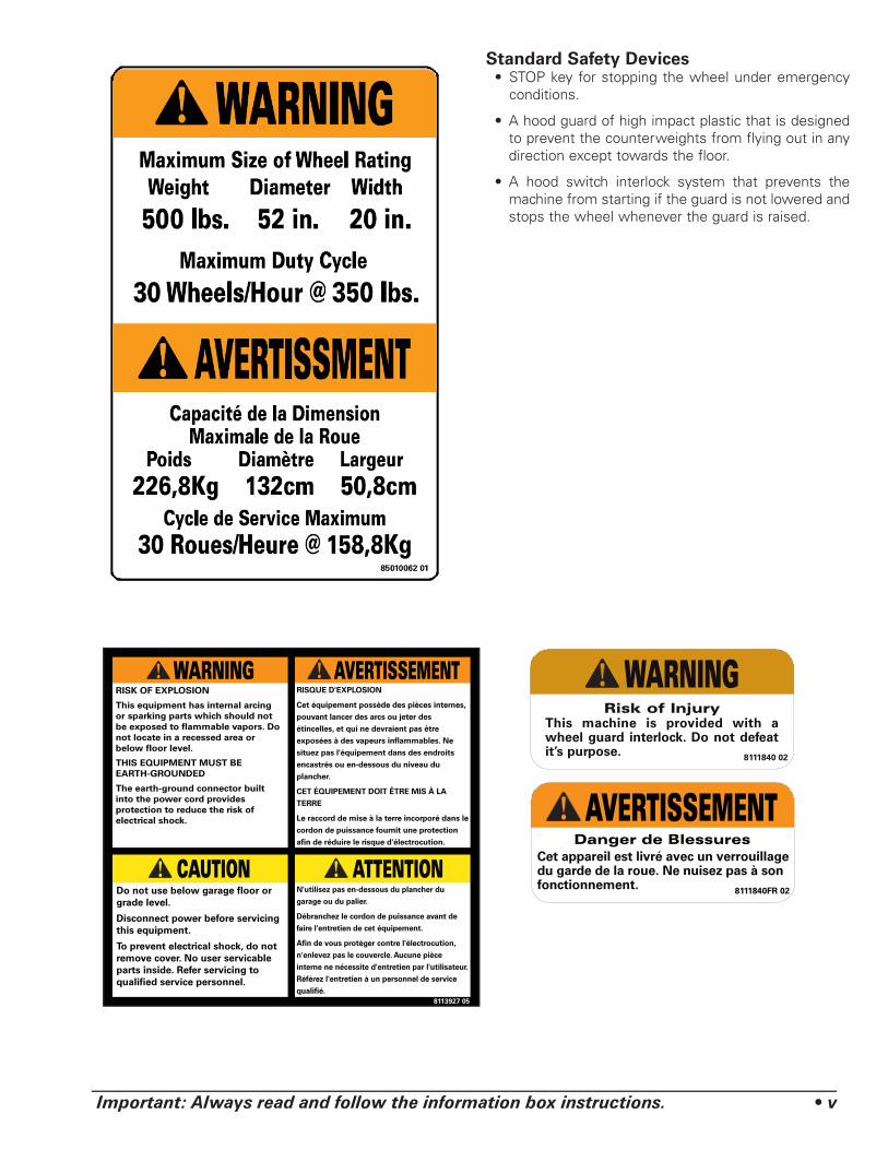
Standard Safety Devices• STOP key for stopping the wheel under emergency
conditions.
• A hood guard of high impact plastic that is designed to prevent the counterweights from flying out in any direction except towards the floor.
• A hood switch interlock system that prevents the machine from starting if the guard is not lowered and stops the wheel whenever the guard is raised.
CAUTION
WARNING
ATTENTION
AVERTISSEMENT
vi • Important: Always read and follow the information box instructions.
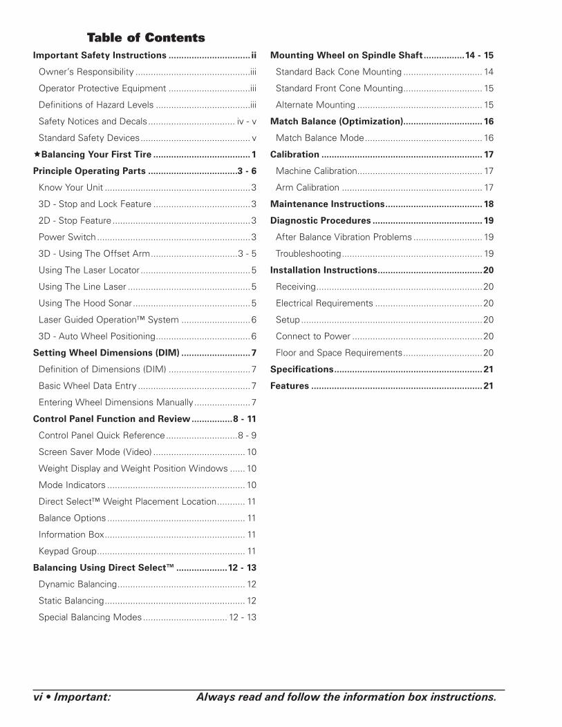
Table of ContentsImportant Safety Instructions ................................ ii
Owner’s Responsibility .............................................iii
Operator Protective Equipment ................................iii
Definitions of Hazard Levels .....................................iii
Safety Notices and Decals .................................. iv - v
Standard Safety Devices ........................................... v
Balancing Your First Tire ......................................1
Principle Operating Parts ...................................3 - 6
Know Your Unit .........................................................3
3D - Stop and Lock Feature ......................................3
2D - Stop Feature ......................................................3
Power Switch ............................................................3
3D - Using The Offset Arm ..................................3 - 5
Using The Laser Locator ...........................................5
Using The Line Laser ................................................5
Using The Hood Sonar ..............................................5
Laser Guided Operation™ System ...........................6
3D - Auto Wheel Positioning .....................................6
Setting Wheel Dimensions (DIM) ...........................7
Definition of Dimensions (DIM) ................................7
Basic Wheel Data Entry ............................................7
Entering Wheel Dimensions Manually ......................7
Control Panel Function and Review ................8 - 11
Control Panel Quick Reference ............................8 - 9
Screen Saver Mode (Video) .................................... 10
Weight Display and Weight Position Windows ...... 10
Mode Indicators ...................................................... 10
Direct Select™ Weight Placement Location ........... 11
Balance Options ...................................................... 11
Information Box ....................................................... 11
Keypad Group .......................................................... 11
Balancing Using Direct Select™ ....................12 - 13
Dynamic Balancing .................................................. 12
Static Balancing ....................................................... 12
Special Balancing Modes ................................. 12 - 13
Mounting Wheel on Spindle Shaft ................14 - 15
Standard Back Cone Mounting ............................... 14
Standard Front Cone Mounting ............................... 15
Alternate Mounting ................................................. 15
Match Balance (Optimization) ............................... 16
Match Balance Mode .............................................. 16
Calibration ............................................................... 17
Machine Calibration ................................................. 17
Arm Calibration ....................................................... 17
Maintenance Instructions ...................................... 18
Diagnostic Procedures ........................................... 19
After Balance Vibration Problems ........................... 19
Troubleshooting ....................................................... 19
Installation Instructions .........................................20
Receiving .................................................................20
Electrical Requirements ..........................................20
Setup .......................................................................20
Connect to Power ...................................................20
Floor and Space Requirements ...............................20
Specifications .......................................................... 21
Features ................................................................... 21
Important: Always read and follow the information box instructions. • 1
Balancing Your First Tire1. Turn the machine OFF then
ON (resets machine). | Note: The machine wakes up using standard clip-
on wheel weight locations (Clip 1 & Clip 2) and wheel dimensions.
2. Mount a tire/wheel on the bal-ancer that will use standard clip-on wheel weights.
Use the most appropriate mounting method.
3. Always remove any weights already attached to the wheel.
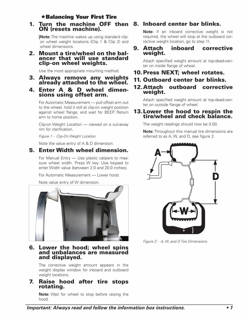
4. Enter A & D wheel dimen-sions using offset arm.
For Automatic Measurement — pull offset arm out to the wheel, hold it still at clip-on weight position against wheel flange, and wait for BEEP. Return arm to home position.
Clip-on Weight Location — viewed on a cut-away rim for clarification.
Figure 1 - Clip-On Weight Location
Note the value entry of A & D dimension.
5. Enter Width wheel dimension. For Manual Entry — Use plastic calipers to mea-
sure wheel width. Press W key. Use keypad to enter Width value (between 2.0 and 20.0 inches).
For Automatic Measurement — Lower hood.
Note value entry of W dimension.
6. Lower the hood; wheel spins and unbalances are measured and displayed.
The corrective weight amount appears in the weight display window for inboard and outboard weight locations.
7. Raise hood after tire stops rotating.
Note: Wait for wheel to stop before raising the hood.
8. Inboard center bar blinks. Note: If an inboard corrective weight is not
required, the wheel will stop at the outboard cor-rective weight location, go to step 11.
9. Attach inboard corrective weight.
Attach specified weight amount at top-dead-cen-ter on inside flange of wheel.
10. Press NEXT; wheel rotates.11. Outboard center bar blinks.12. Attach outboard corrective
weight. Attach specified weight amount at top-dead-cen-
ter on outside flange of wheel.
13. Lower the hood to respin the tire/wheel and check balance.
The weight readings should now be 0.00.
Note: Throughout this manual tire dimensions are referred to as A, W, and D, see figure 2.
Figure 2 - A, W, and D Tire Dimensions
2 • Important: Always read and follow the information box instructions.
Principle Operating Parts

Important: Always read and follow the information box instructions. • 3
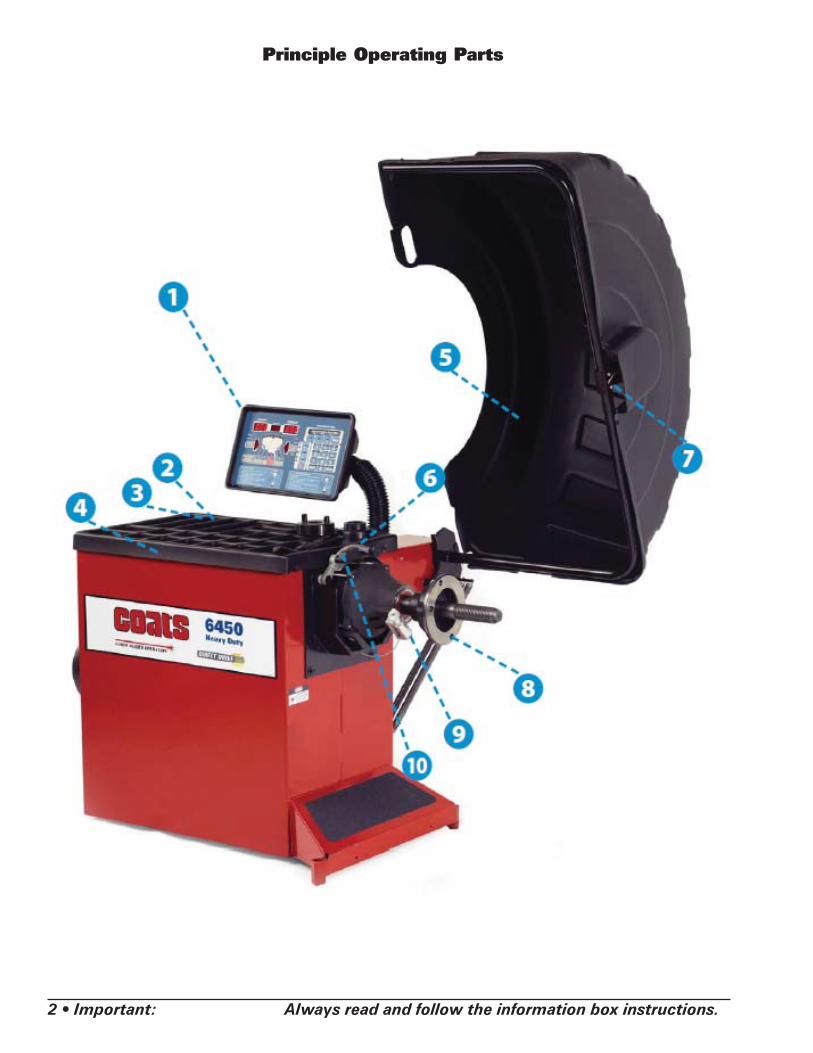
Know Your UnitCompare this illustration with the unit before placing
it into service. Maximum performance and safety will be obtained only when all persons using the unit are fully trained in its parts and operation. Each user should learn the function and location, of all controls.
Prevent accidents and injuries by ensuring the unit is properly installed, operated and maintained.
Control Panel
Plug (back of machine)
ON/OFF
Weight Tray with Pockets for Tape-A-Weight Boxes; Individual Weights
J Hood Guard
Offset Arm, Measures A & D of Tire/Wheel (shown in home position)
Hood Sonar - Width Sensor (3D model only)
50mm Shaft
Locator Laser
Line Laser
Note: Throughout this manual wheel weights are referred to as Clip-on or Tape-A-Weight®. Figure 3 shows an example of each weight.
Figure 3 - Corrective Weight Examples. For Best Results, use
BADA® Brand Wheel Weights.
3D - Stop and Lock FeatureThe balancer will stop the wheel on the inner plane
first if a weight is needed on the inner plane. If no weight is needed on inner plane, the wheel will stop at the outer plane first. If in fine balancing mode, the wheel will stop at plane that calls for most weight.
2D - Stop FeatureAt the completion of the balance cycle, the wheel
assembly will come to a complete stop; then the drive will release the wheel. Then the operator can manually index to the proper plane using the indexing guides on the front panel.
Power SwitchThe ON/OFF decal (figure 4) indicates the ON/OFF
switch location at the back of the balancer.
Figure 4 - On/Off Switch
Using The Offset ArmWhen not in use or when prompted by the balancer
instructions, store the offset arm in the home position as shown in figure 5.
Figure 5 - Offset Arm Stored In Home Position
Clip-on Weight Tape-A-Weight®
ON/OFF Power Switch
Offset Arm In Home Position

4 • Important: Always read and follow the information box instructions.
When prompted by balance r instructions, use the offset arm (figure 6A) to enter A & D measurements automatically. Pull the arm out and up against the wheel flange; hold it still at the clip-on weight location (figure 6B), against the wheel flange, and wait for the BEEP.
Figure 6A - Automatic A&D Measurement At Clip-on Weight Location
Be sure to place the offset arm on the wheel flange at the clip- on weight location as shown figure 6B.
Figure 6B - Clip-on Weight Location Viewed on a Cut-Away Rim for Clarification.
Note: Use the offset arm to automatically measure the A & D dimension for all balancing modes except Patch Static (refer to page 13 Patch Weight Balance).
Note: Refer to page 7 to measure the A dimension manually using the offset arm.
Note: The T2 - Tape Direct Select™ Weight position is the only mode that requires the A2 & D2 dimension measurements.
Note: Use laser locators for correct positioning of the T2 - Tape Direct Select™ Weight position, refer to pages 5 - 6.
If the T2 - Tape (hidden Tape-A-Weight®) location is selected, use the offset arm to enter A2 & D2 measure-ments automatically. After the A & D measurement is entered, move the arm from the clip-on weight location to the inner area of the wheel; up against the rim at the outboard weight placement location (see figures 7A & 7B). Wait for the BEEP.
Figure 7A - Hidden Weight Location Viewed on a Cut-Away Rim for Clarification.
Important: The A2 measurement must be at least 2 inches greater than the A1 measurement.
Figure 7B - T2-Tape (Hidden Tape-A-Weight®) Keep At Least 2-inches Between A1 and A2 Measurement
Offset Arm In Home Position
At least2-Inch
minimumdifference
A1 A2

Important: Always read and follow the information box instructions. • 5
Figure 7C - T2-Tape (Hidden Tape-A-Weight®) Data Entry Diagram
Using The Laser LocatorIf the T2 - Tape (hidden Tape-A-Weight®) location is
selected, use the laser locator to point to the hidden weight location (figures 8 & 7B). Rotate laser locator knob to position the laser dot outboard at the desired T2-Tape (hidden Tape-A-Weight®) location.
Note: For best performance, choose a weight position outboard as far inward (in the rim) as wheel allows.
Figure 8 - Positioning Laser Dot At T2 - Tape Hidden Weight Location (A2)
Note: The T2 - Tape Direct Select™ Weight position is the only mode that requires the A2 & D2 dimension measurements.
Using The Line LaserIf the T2 - Tape (hidden Tape-A-Weight®) location
is selected, use the line laser to align the offset arm with the laser locator dot (figures 8 & 7B); entering A2 & D2 measurements automatically. Grasp arm at the line laser and pull out and up to the wheel flange (figure 6B). Hold arm still at the clip-on weight location and wait for BEEP. Then, before returning arm to home position, press button on line laser to activate the line laser beam. Move arm to inner area of wheel and align line laser beam with laser locator dot (figure 8). Hold arm still, up against the rim, in the same plane as the T2-Tape (hidden Tape-A-Weight®) location (figure 7A & 7B) and wait for BEEP. Refer to figure 9.
Note: The line laser remains on for ten seconds after its button is pushed.
Figure 9 - Positioning Line Laser Beam At T2 - Tape Hidden Weight Location (A2)
3D - Using the Hood SonarWhen prompted by the balancer instructions, use the
hood sonar - width sensor (figure 10) to enter wheel width measurement automatically. Lower balancer hood guard to enter the measurement.
Figure 10 - Tire Width Sonar Located Inside Hood
Note: Refer to page 7 to measure the W dimension manually using the plastic calipers (2D & 3D models).
Laser Locator
Dot
Laser Locator Knob
Center Line Laser Beam
on Laser Locator Dot
Press LineLaser Button

6 • Important: Always read and follow the information box instructions.
Laser Guided Operation™ SystemThe operator must select T2 - Tape Laser Locator to
activate the Laser Guided Operation™ feature, see page 8 for the button selection. This Direct Select™ weight location is used when placing hidden adhesive weights at the inner area of the wheel and is the required weight location selection for the Behind Spoke mode.
Follow these steps to use the Laser Guided Opera-tion™ feature for accurate placement of hidden Tape-A-Weights®:
Important: Only use the Direct Select Weight posi-tion Clip 1 or T1 - Tape and T2 - Tape (location illuminated). Refer to Using The Offset Arm on page 4 and Using The Lasers on page 5.
1. Begin by mounting the wheel assembly.
2. Be sure to Direct Select™ T2 - Tape as the out-board weight location (refer to Dynamic Balance, Hid-den Tape-A-Weights, page 12).
Note: The laser locator dot activates and blinks.
3. Rotate the laser locator knob to position the laser locator dot at the desired weight location. See figures 8 & 7B.
Note: For best performance, choose a weight position outboard as far inward (in the rim) as wheel allows.
4. Enter the A & D wheel measurements, wait for BEEP. Then, before returning arm to home position, move arm to inner area of wheel and position the line laser beam at the T2 - Tape laser locator dot position; wait for BEEP.
5. Lower hood; wheel spins.
6. 2D Model - When wheel comes to a complete stop, manually rotate wheel until the inboard center bar blinks. Attach inboard corrective weight at top-dead-center.
3D Model - Wheel will come to a complete stop at the inboard weight position, center bar blinks. Attach inboard corrective weight at top-dead-center.
Note: If an inboard corrective weight is not required then the wheel will stop at the outboard corrective weight location.
7. 2D Model - Manually rotate wheel to outboard cor-rective weight location where the outboard center bar is steady and the two bars on either side blink.
3D Model - Press NEXT to rotate wheel to outboard corrective weight location where the outboard center bar is steady and the two bars on either side blink.
Note: The laser locator dot will stop blinking.
8. Center and attach the outboard corrective weight at laser locator dot location as shown in figure 11.
9. Respin tire/wheel to check balance.
Figure 11 - Centering Corrective Hidden Weight At Laser Loca-tor Dot Location
3D - Auto Wheel Positioning
CAUTIONKeep hair, loose clothing, fingers and all parts of body away from moving parts.
The balancer’s auto positioning feature stops the wheel automatically at the corrective weight location. The wheel is spun and unbalances are measured and displayed. The inboard center bar blinks as the balancer stops the wheel at the inboard corrective weight loca-tion (top-dead-center). (If an inboard corrective weight is not required then the wheel will stop at the outboard corrective weight location.) Press NEXT. The outboard center bar blinks as the wheel automatically moves and stops at the outboard corrective weight location (top-dead-center).
Pressing NEXT moves the wheel automatically to the next corrective weight location. Pressing EXIT releases the wheel so that it can be manually positioned.
After several minutes of inactivity, the auto position-ing feature will turn it self off. Press NEXT to make the feature activate again.
Center Corrective Weight At Laser Locator Dot Location
Important: Always read and follow the information box instructions. • 7
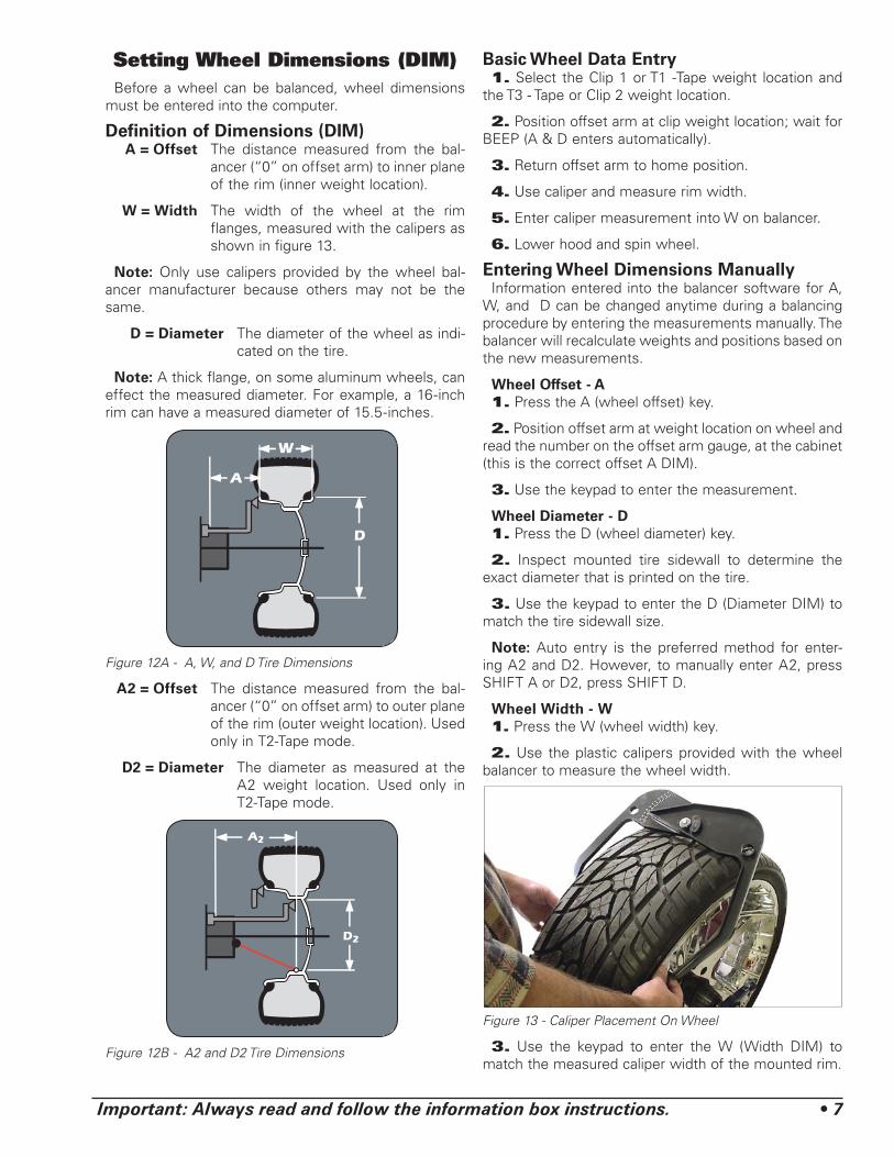
Setting Wheel Dimensions (DIM)Before a wheel can be balanced, wheel dimensions
must be entered into the computer.
Definition of Dimensions (DIM) A = Offset The distance measured from the bal-
ancer (“0” on offset arm) to inner plane of the rim (inner weight location).
W = Width The width of the wheel at the rim flanges, measured with the calipers as shown in figure 13.
Note: Only use calipers provided by the wheel bal-ancer manufacturer because others may not be the same.
D = Diameter The diameter of the wheel as indi-cated on the tire.
Note: A thick flange, on some aluminum wheels, can effect the measured diameter. For example, a 16-inch rim can have a measured diameter of 15.5-inches.
Figure 12A - A, W, and D Tire Dimensions
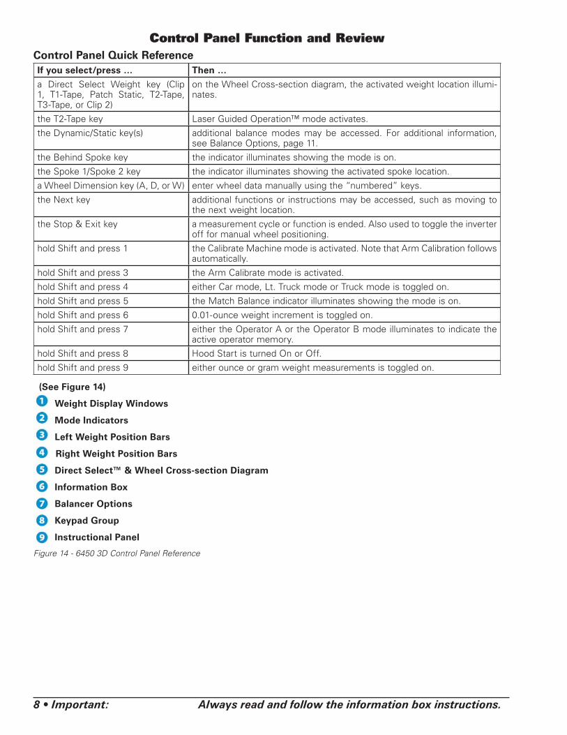
A2 = Offset The distance measured from the bal-ancer (“0” on offset arm) to outer plane of the rim (outer weight location). Used only in T2-Tape mode.
D2 = Diameter The diameter as measured at the A2 weight location. Used only in T2-Tape mode.
Figure 12B - A2 and D2 Tire Dimensions
Basic Wheel Data Entry1. Select the Clip 1 or T1 -Tape weight location and
the T3 - Tape or Clip 2 weight location.
2. Position offset arm at clip weight location; wait for BEEP (A & D enters automatically).
3. Return offset arm to home position.
4. Use caliper and measure rim width.
5. Enter caliper measurement into W on balancer.
6. Lower hood and spin wheel.
Entering Wheel Dimensions ManuallyInformation entered into the balancer software for A,
W, and D can be changed anytime during a balancing procedure by entering the measurements manually. The balancer will recalculate weights and positions based on the new measurements.
Wheel Offset - A1. Press the A (wheel offset) key.
2. Position offset arm at weight location on wheel and read the number on the offset arm gauge, at the cabinet (this is the correct offset A DIM).
3. Use the keypad to enter the measurement.
Wheel Diameter - D1. Press the D (wheel diameter) key.
2. Inspect mounted tire sidewall to determine the exact diameter that is printed on the tire.
3. Use the keypad to enter the D (Diameter DIM) to match the tire sidewall size.
Note: Auto entry is the preferred method for enter-ing A2 and D2. However, to manually enter A2, press SHIFT A or D2, press SHIFT D.
Wheel Width - W1. Press the W (wheel width) key.
2. Use the plastic calipers provided with the wheel balancer to measure the wheel width.
Figure 13 - Caliper Placement On Wheel
3. Use the keypad to enter the W (Width DIM) to match the measured caliper width of the mounted rim.
8 • Important: Always read and follow the information box instructions.
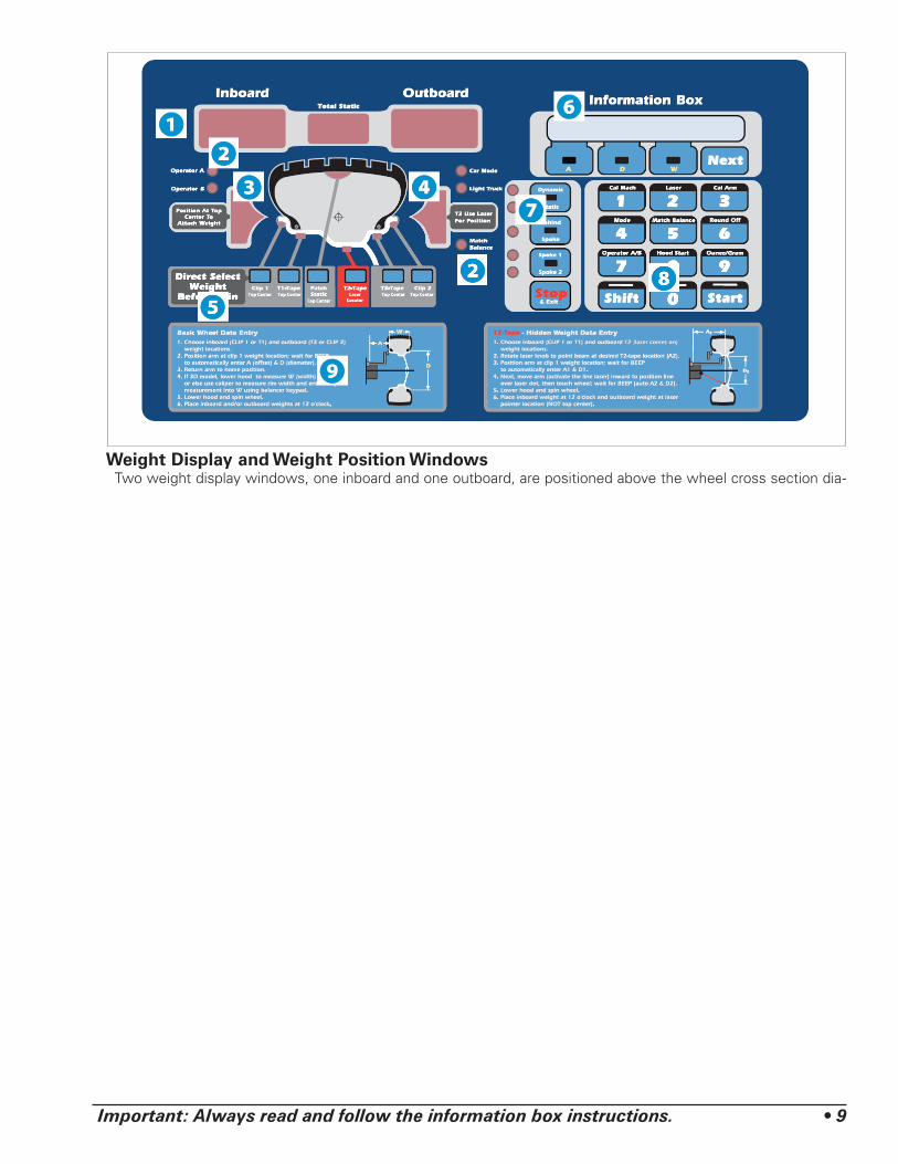
Control Panel Function and ReviewControl Panel Quick ReferenceIf you select/press … Then …
a Direct Select Weight key (Clip 1, T1-Tape, Patch Static, T2-Tape, T3-Tape, or Clip 2)
on the Wheel Cross-section diagram, the activated weight location illumi-nates.
the T2-Tape key Laser Guided Operation™ mode activates.
the Dynamic/Static key(s) additional balance modes may be accessed. For additional information, see Balance Options, page 11.
the Behind Spoke key the indicator illuminates showing the mode is on.
the Spoke 1/Spoke 2 key the indicator illuminates showing the activated spoke location.
a Wheel Dimension key (A, D, or W) enter wheel data manually using the “numbered” keys.
the Next key additional functions or instructions may be accessed, such as moving to the next weight location.
the Stop & Exit key a measurement cycle or function is ended. Also used to toggle the inverter off for manual wheel positioning.
hold Shift and press 1 the Calibrate Machine mode is activated. Note that Arm Calibration follows automatically.
hold Shift and press 3 the Arm Calibrate mode is activated.
hold Shift and press 4 either Car mode, Lt. Truck mode or Truck mode is toggled on.
hold Shift and press 5 the Match Balance indicator illuminates showing the mode is on.
hold Shift and press 6 0.01-ounce weight increment is toggled on.
hold Shift and press 7 either the Operator A or the Operator B mode illuminates to indicate the active operator memory.
hold Shift and press 8 Hood Start is turned On or Off.
hold Shift and press 9 either ounce or gram weight measurements is toggled on.
(See Figure 14)
Weight Display Windows
Mode Indicators
Left Weight Position Bars
Right Weight Position Bars
Direct Select™ & Wheel Cross-section Diagram
Information Box
Balancer Options
Keypad Group
Instructional Panel
Figure 14 - 6450 3D Control Panel Reference
Important: Always read and follow the information box instructions. • 9
Weight Display and Weight Position WindowsTwo weight display windows, one inboard and one outboard, are positioned above the wheel cross section dia-
10 • Important: Always read and follow the information box instructions.
gram. After a wheel measurement cycle, the balancer calculates the corrective weight amount and indicates it in the appropriate display window. All weight readings are shown in ounces or grams.
The “Total Static” window indicates the value of the total static unbalance. See MATCH BALANCE (Optimi-zation) on page 16 for further details.
Located on either side of the wheel cross section dia-gram are the weight position bars, one inboard and one outboard. After a measurement cycle, rotate wheel until the center weight position bar blinks, indicating the cor-rect weight placement position is at top-dead-center.
Note: When in laser mode (T2-Tape Laser Locator), special blinking bars appear on either side of the center bar to indicate the correct outboard weight placement position. Also remember that the laser beam dot will stop blinking when it is at the correct weight placement location.
Mode IndicatorsThe mode indicator will show whether the mode is
activated. Modes are as follows:
Operator A or Operator B - when illuminated, indicates which operator memory is selected.
Match Balance - when illuminated, indicates that the Match Balance (Optimization) mode is activated.
Car Mode - 0.25-ounce round off mode is active when the car mode light is lit.
Lt. Truck Mode - 0.50-ounce round off mode is active when the light truck mode light is lit.
Truck Mode - 2.00-ounce round off mode is active when both the car mode and light truck mode lights are off. This is the default condition when machine is powered on.
Dynamic or Static - press to cycle through balance modes. For additional information, see Balance Options, page 11.
Behind Spoke - when illuminated, indicates that the behind spoke mode is activated.
Spoke 1 or Spoke 2 - when illuminated, indicates spoke location selection.

Important: Always read and follow the information box instructions. • 11
Direct Select™ Weight Placement LocationBefore spinning the wheel, use direct select to indi-
cate weight placement locations as follows:
Note: When the machine is turned ON, the balancer defaults to truck mode and 2-plane dynamic mode using standard clip-on wheel weight locations (Clip 1 and Clip 2) and wheel dimensions.
Clip 1 Top Center - select this location to place a stan-dard clip weight on the inboard rim flange.
T-1 Tape Top Center - select this location to place an adhesive weight on the inboard side of the wheel that is the horizontal plane at the outer edge.
Patch Static - select this location for a patch weight centered inside the tire. See Patch Weight Balance on page 13 for further details.
T-2 Tape Laser Locator - select this location to place an adhesive (hidden) weight on the outboard side of the wheel that is a horizontal plane in the inner area. See Laser Guided Operation™ System on page 6 for further details.
T-3 Tape Top Center - select this location to place an adhesive weight on the outboard side of the wheel that is the horizontal plane at the outer edge.
Clip 2 Top Center - select this location to place a stan-dard clip weight on the outboard rim flange.
Balance OptionsThe indicator will illuminate to show the active balance
option. Functions are as follows:
Dynamic/Static - press the respective key to cycle through either a Dynamic, a Dynamic with Total Static displayed, a Static, or the EB (if feature is available and enabled, see page 12) balance mode.
LED Indicatorsfor 6450
LED Status Balance Mode
Both LEDs Lit Dynamic
Top LED Lit Dynamic/Total Static
Bottom LED Lit Static
Behind Spoke - toggle the Behind Spoke option on or off. See Behind Spoke on page 12 for further details.
Spoke 1/Spoke 2 - toggle to set the Spoke 1 location and the Spoke 2 location for adhesive weights (hidden weights).
Information BoxDisplays A, W, and D values, functions, and instruc-
tions for the operator. Error messages will also be shown in this display.
Keypad GroupThe operator enters wheel data information, selects
functions, and sets options using these keys.
“Numbered” Keys - use to enter wheel data values.
Cal Mach - press and hold the SHIFT key and press 1 to activate Calibrate Machine mode. See Machine Cali-bration on page 17 for further details.
Match Balance - press and hold the SHIFT key and press 5 to select the Match Balance mode. See Match Balance (Optimization) on page 16 for further details.
Round Off - press and hold the SHIFT key and press 6 to toggle between either roundoff (0.25, 0.50 or 2.00-ounce) or fine (0.01-ounce) weight increments.
Operator A/B - press and hold the SHIFT key and press 7 to toggle between two operator memories (A or B). The default memory is Operator A.
Hood Start - when on, sets the balancer to automati-cally start the spin cycle as soon as the hood is lowered completely and the hood safety interlock system is engaged. Press and hold the SHIFT key and press 8 to toggle Hood Start on or off. The default is on.
Ounce/Gram - press and hold the SHIFT key and press 9 to toggle between either ounce or gram weight mea-surements. The default is ounce.
Stop & Exit - press STOP to end a measurement cycle, exit a function or a mode.
Start - press START to begin a measurement cycle, if the hood is lowered.
Next - function key used when accessing balancer instructions and, if balancer is 3D and equipped with an inverter, automatically rotates tire to its next weight placement position.
Shift - function key used when accessing balancer modes or options.
12 • Important: Always read and follow the information box instructions.
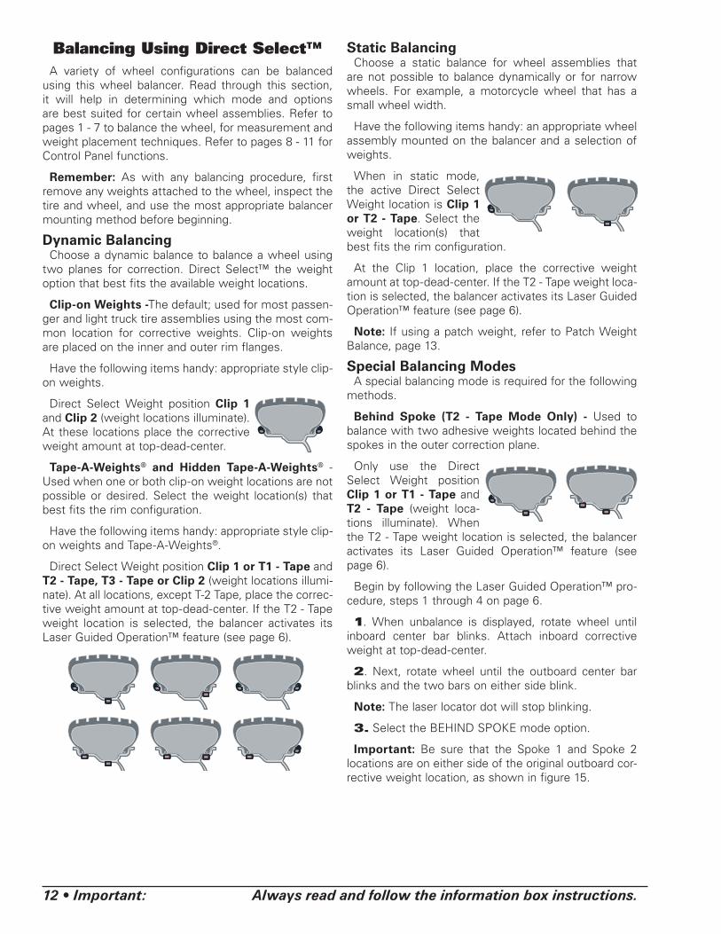
Balancing Using Direct Select™A variety of wheel configurations can be balanced
using this wheel balancer. Read through this section, it will help in determining which mode and options are best suited for certain wheel assemblies. Refer to pages 1 - 7 to balance the wheel, for measurement and weight placement techniques. Refer to pages 8 - 11 for Control Panel functions.
Remember: As with any balancing procedure, first remove any weights attached to the wheel, inspect the tire and wheel, and use the most appropriate balancer mounting method before beginning.
Dynamic BalancingChoose a dynamic balance to balance a wheel using
two planes for correction. Direct Select™ the weight option that best fits the available weight locations.
Clip-on Weights -The default; used for most passen-ger and light truck tire assemblies using the most com-mon location for corrective weights. Clip-on weights are placed on the inner and outer rim flanges.
Have the following items handy: appropriate style clip-on weights.
Direct Select Weight position Clip 1 and Clip 2 (weight locations illuminate). At these locations place the corrective weight amount at top-dead-center.
Tape-A-Weights® and Hidden Tape-A-Weights® - Used when one or both clip-on weight locations are not possible or desired. Select the weight location(s) that best fits the rim configuration.
Have the following items handy: appropriate style clip-on weights and Tape-A-Weights®.
Direct Select Weight position Clip 1 or T1 - Tape and T2 - Tape, T3 - Tape or Clip 2 (weight locations illumi-nate). At all locations, except T-2 Tape, place the correc-tive weight amount at top-dead-center. If the T2 - Tape weight location is selected, the balancer activates its Laser Guided Operation™ feature (see page 6).
Static BalancingChoose a static balance for wheel assemblies that
are not possible to balance dynamically or for narrow wheels. For example, a motorcycle wheel that has a small wheel width.
Have the following items handy: an appropriate wheel assembly mounted on the balancer and a selection of weights.
When in static mode, the active Direct Select Weight location is Clip 1 or T2 - Tape. Select the weight location(s) that best fits the rim configuration.
At the Clip 1 location, place the corrective weight amount at top-dead-center. If the T2 - Tape weight loca-tion is selected, the balancer activates its Laser Guided Operation™ feature (see page 6).
Note: If using a patch weight, refer to Patch Weight Balance, page 13.
Special Balancing ModesA special balancing mode is required for the following
methods.
Behind Spoke (T2 - Tape Mode Only) - Used to balance with two adhesive weights located behind the spokes in the outer correction plane.
Only use the Direct Select Weight position Clip 1 or T1 - Tape and T2 - Tape (weight loca-tions illuminate). When the T2 - Tape weight location is selected, the balancer activates its Laser Guided Operation™ feature (see page 6).
Begin by following the Laser Guided Operation™ pro-cedure, steps 1 through 4 on page 6.
1. When unbalance is displayed, rotate wheel until inboard center bar blinks. Attach inboard corrective weight at top-dead-center.
2. Next, rotate wheel until the outboard center bar blinks and the two bars on either side blink.
Note: The laser locator dot will stop blinking.
3. Select the BEHIND SPOKE mode option.
Important: Be sure that the Spoke 1 and Spoke 2 locations are on either side of the original outboard cor-rective weight location, as shown in figure 15.

Important: Always read and follow the information box instructions. • 13
4. Rotate the wheel toward front so the laser locator dot is behind the first spoke; press SPOKE 1 (indicator illuminates).
5. Rotate the wheel toward rear so the laser loca-tor dot is behind the second spoke; press SPOKE 2 (indicator illuminates). Now at the spoke 2 location, the outboard center bar stops blinking and the two bars on either side blink.
Note: The laser locator dot will stop blinking.
Figure 15 - Spoke 1 And Spoke 2 Locations On Either Side Of Original Outboard Weight Location
6. Center and attach the spoke 2 outboard corrective weight at the laser locator dot location (see figure 11 page 6).
7. Next, rotate the wheel toward the spoke 1 location until the outboard center bar stops blinking and the two bars on either side blink.
Note: The laser locator dot will stop blinking.
8. Center and attach the spoke 1 outboard corrective weight at the laser locator dot location (see figure 11 page 6).
9. Respin tire/wheel to check balance.
Patch Weight Balance - Use a static patch weight balance when there is a very large unbalance in a tire assembly or if a very large tire has a large unbalance. A weighted balance pad (patch weight) is placed inside the tire in the center to compensate for the large unbal-ance.
Direct Select Weight position Patch Static (weight location illuminates). At this location place the corrective weight amount at top-dead-center.
Have the following items handy: mea-suring tape and various patch weight sizes.
Note: Before proceeding with Patch Weight Balance, it is recommended that you use the Match Balance (Optimization) procedure first, see page 16, in order to use the smallest patch weight.
The Patch Weight Balance involves the loos-ening of tire beads and the inflation of a tire. Training is necessary in tire changer operation and understanding the dangers involved during bead seating and tire infla-tion before attempting this stage of the Patch Weight Balance procedure. Read the operators manual supplied with the tire changer and consult a supervisor.
The patch weight balance steps are as follows:
1. Direct Select Weight position PATCH STATIC. The balancer automatically sets itself for a STATIC balance.
2. Measure the outside tire diameter, see figure 16, and enter this diameter manually using the keypad.
Figure 16 - Measure Outside Tire Diameter
3. Spin the wheel.
4. Rotate the wheel until the center weight position bar blinks. Next, mark the tire and rim at 12 o’clock. Then remove the wheel assembly from the machine.
5. Disassemble the tire and rim. Place patch weight in the tire at location marked on the tire. Reassemble tire and rim matching the marks on the tire and rim.
6. Complete by balancing the wheel assembly follow-ing normal procedures.
OutsideDiameter

14 • Important: Always read and follow the information box instructions.
Mounting Wheel on Spindle Shaft
CAUTIONAvoid back injury, seek assistance when lifting heavy tire/rim assemblies onto the balancer shaft.
CAUTIONHubnut must engage threads for at least four full turns. Failure to tighten hubnut securely or to force wheel firmly against the faceplate may result in serious personal injury.
Select the most appropriate mounting method for the wheel you are balancing. Using the proper method ensures secure mounting and safe balancer operation, and prevents damage to the wheel.
On most wheels, the inner side of the wheel hub usu-ally has the most uniform surface for wheel balancing. Always center the wheel by the most uniform shaped side of the hub to achieve the most accurate balance.
Regardless of mounting type, always make sure that the wheel is forced firmly against the shaft faceplate and that the hub nut engages the threaded shaft for at least four complete turns. To assist in centering the wheel properly, rotate the wheel and the shaft while tightening the hub nut.
Standard Back Cone MountingUse only small or medium cones.
1. Place spring over threaded stud with the large end inside of the faceplate. Spring must be used.
2. Select a cone that best fits into wheel center hole. Use only small or medium cones. If a larger cone is required, use the front cone mounting system.
3. Slide selected cone onto threaded shaft with the large end against the spring.
4. Lift wheel onto shaft and center on cone.
5. Slide pressure drum onto threaded shaft with the large end against the spring.
6. Thread hubnut on and tighten with hubnut wrench. If hubnut won’t tighten all the way down, use the front cone mounting system. The wheel must be forced firmly against the faceplate.
7. If you still can’t tighten hubnut because of a lack of threads, use an additional cone to act as a spacer between the hubnut and pressure drum.
Figure 17 - Back Cone Mounting
Important: Always read and follow the information box instructions. • 15
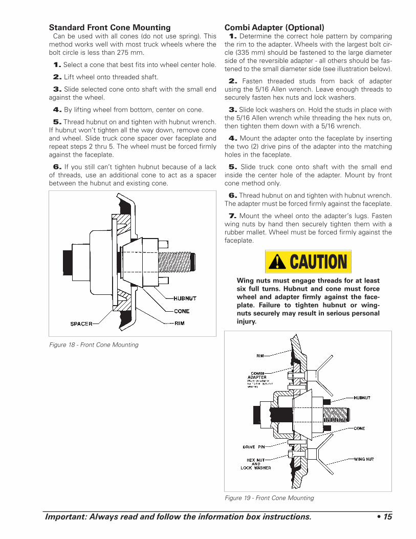
Standard Front Cone MountingCan be used with all cones (do not use spring). This
method works well with most truck wheels where the bolt circle is less than 275 mm.
1. Select a cone that best fits into wheel center hole.
2. Lift wheel onto threaded shaft.
3. Slide selected cone onto shaft with the small end against the wheel.
4. By lifting wheel from bottom, center on cone.
5. Thread hubnut on and tighten with hubnut wrench. If hubnut won’t tighten all the way down, remove cone and wheel. Slide truck cone spacer over faceplate and repeat steps 2 thru 5. The wheel must be forced firmly against the faceplate.
6. If you still can’t tighten hubnut because of a lack of threads, use an additional cone to act as a spacer between the hubnut and existing cone.
Figure 18 - Front Cone Mounting
Combi Adapter (Optional)1. Determine the correct hole pattern by comparing
the rim to the adapter. Wheels with the largest bolt cir-cle (335 mm) should be fastened to the large diameter side of the reversible adapter - all others should be fas-tened to the small diameter side (see illustration below).
2. Fasten threaded studs from back of adapter using the 5/16 Allen wrench. Leave enough threads to securely fasten hex nuts and lock washers.
3. Slide lock washers on. Hold the studs in place with the 5/16 Allen wrench while threading the hex nuts on, then tighten them down with a 5/16 wrench.
4. Mount the adapter onto the faceplate by inserting the two (2) drive pins of the adapter into the matching holes in the faceplate.
5. Slide truck cone onto shaft with the small end inside the center hole of the adapter. Mount by front cone method only.
6. Thread hubnut on and tighten with hubnut wrench. The adapter must be forced firmly against the faceplate.
7. Mount the wheel onto the adapter’s lugs. Fasten wing nuts by hand then securely tighten them with a rubber mallet. Wheel must be forced firmly against the faceplate.
CAUTIONWing nuts must engage threads for at least six full turns. Hubnut and cone must force wheel and adapter firmly against the face-plate. Failure to tighten hubnut or wing-nuts securely may result in serious personal injury.
Figure 19 - Front Cone Mounting

16 • Important: Always read and follow the information box instructions.
Match Balance (Optimization)The Match Balance (Tire/Rim Weight Optimization)
procedure is used to determine the best mating of tire and rim that will result in the least amount of total unbal-ance of the assembly. It requires two spins and two rotations of the tire on the rim. Match Balance may be needed when:
• The customer complains of ride problems.
Note: A high unbalance may indicate the improper mounting of the assembly on the balancer, or a rim that is out of round or malformed, or a tire with a bubble or other problem. If the unbalance is excessive, it may be prudent to replace the rim, the tire, or both. If either is replaced, do not continue with Match Balance. Balance the new tire and rim and evaluate the readings.
Match Balance ModeIf you choose to use Match Balance to correct for a
condition, such as a large static unbalance, then follow the information box instructions for the MATCH BAL-ANCE procedure as outlined in the following steps.
Note: Use this procedure only after the wheel has spun and the corrective weight amount is displayed.
Note: Use the total static display option. See BAL-ANCE OPTIONS, page 11, for further details.
1. Press and hold the SHIFT key and press 5 to select the Match Balance mode. A “1” will appear in the out-board weight display.
2. Raise the hood and rotate the wheel until the valve stem is at top-dead-center. Mark the tire sidewall at the valve stem.
3. Press 1 on the control panel; a “2” will appear in the outboard weight display.
4. Remove the wheel assembly from the balancer.
The Match Balance involves the loosening of tire beads and the inflation of a tire. Training is necessary in tire changer operation and understanding the dangers involved dur-ing bead seating and tire inflation before attempting this stage of the Match Balance procedure. Read the operators manual sup-plied with the tire changer and consult a supervisor.
5. Using a tire changer, rotate the tire 180 degrees on the rim.
6. Remount wheel assembly on the balancer. Press 2 on the control panel; a “3” will appear in the outboard weight display.
7. Lower the hood and press START. The wheel spins.
8. When the wheel stops spinning, raise the hood and rotate the wheel until the valve stem is at top-dead-center.
9. Press 4 on the control panel.
Weight amounts appear on the control panel. The amount in the inboard weight display is the weight imbalance for the rim. The amount in the outboard weight display is the weight imbalance for the tire. Use these weight amounts to determine the suitability of the rim or tire.
Note: If either the rim or the tire weight amount is close to zero or zero then using Match Balance will not affect the total unbalance of the assembly.
10. Rotate the wheel until the outboard weight posi-tion bar flashes. Mark the tire at top-dead-center.
11. Remove wheel assembly from balancer.
The Match Balance involves the loosening of tire beads and the inflation of a tire. Training is necessary in tire changer operation and understanding the dangers involved dur-ing bead seating and tire inflation before attempting this stage of the Match Balance procedure. Read the operators manual sup-plied with the tire changer and consult a supervisor.
12. Using a tire changer, rotate the tire until the mark is aligned with the valve stem.
13. Remount the wheel assembly on the balancer.
14. Press NEXT or START to exit Match Balance. Select a balancing mode and balance the wheel assem-bly.

Important: Always read and follow the information box instructions. • 17
CalibrationMachine Calibration
Important: Use the correct calibration weight amount: a 4-ounce calibration weight in ounce mode.
Important: The factory default is set for a 4-ounce calibration weight amount for both ounce and gram weight measurement modes. Therefore only a 4-ounce calibration weight is necessary, regardless of weight measurement mode setting.
Important: Before beginning calibration, be sure the balancer is in fine balance mode by pressing the SHIFT key and 6 to toggle to 0.01 oz. display mode; and bal-ance the tire down below 0.20 oz.
1. It is necessary to machine calibrate at least once in both Truck and Car modes. Start calibration as follows:
Truck Mode - Hold SHIFT key and press 4 until both Car Mode and Light Truck LEDs are toggled off (both lights OFF IS Truck Mode). Then, mount a R11 22.5 steer tire/wheel assembly on the balancer.
Note: Once both Truck and Car modes are initially cali-brated, then it is only necessary to calibrate in the mode that requires calibration. For example, if only truck tires are balanced on this machine, then only the machine calibration in Truck Mode is required.
Important: A balanced tire/wheel assembly is required.
Note: Position wheel so that no weights are on either flange at the top-dead-center location. Turn the machine OFF then ON.
2. Hold SHIFT key and press 1 to select the CAL MACHINE mode.
3. Enter the D dimension.
4. Lower the hood and press START.
5. After spin, raise the hood. Attach calibration weight to the outside flange at top-dead-center.
Figure 20 - Calibration Weight On Outside Flange At Top-Dead-Center
6. Lower the hood and press START.
Important: It is critical that the inner weight be placed accurately to achieve proper calibration. If the calibration weight is not moved from the outside flange directly across to the inside flange, an inner weight placement error will occur. To correct, follow the infor-mation box instructions.
7. After spin, raise the hood. Move and attach the cal-ibration weight to the inside flange at top-dead-center.
Figure 21 - Calibration Weight Moved (Directly Across) To Inside Flange
8. Lower the hood and press START.
9. Calibration complete. Press NEXT.
10. After completing the Machine Calibration proce-dure, the Arm Calibration will automatically initiate.
Arm CalibrationThe Arm Calibration procedure begins immediately
after Machine Calibration.
During Machine Calibration, the balancer software calculates both the A and W dimensions. The Arm Cali-bration gives the balancer software a reference point to the edge of the faceplate and home position. When the user enters the A dimension from the arm rod, it calculates the difference from the machine calibration A and uses that as a factor for the manual A entry. Arm calibration also gives the D dimension a reference point from home position.
11. Bring the tip edge of the arm precisely to the outer edge of the faceplate and hold it there while pressing the NEXT key. (If necessary to reach the faceplate accurately, loosen the calibration wheel tem-porarily.)
18 • Important: Always read and follow the information box instructions.
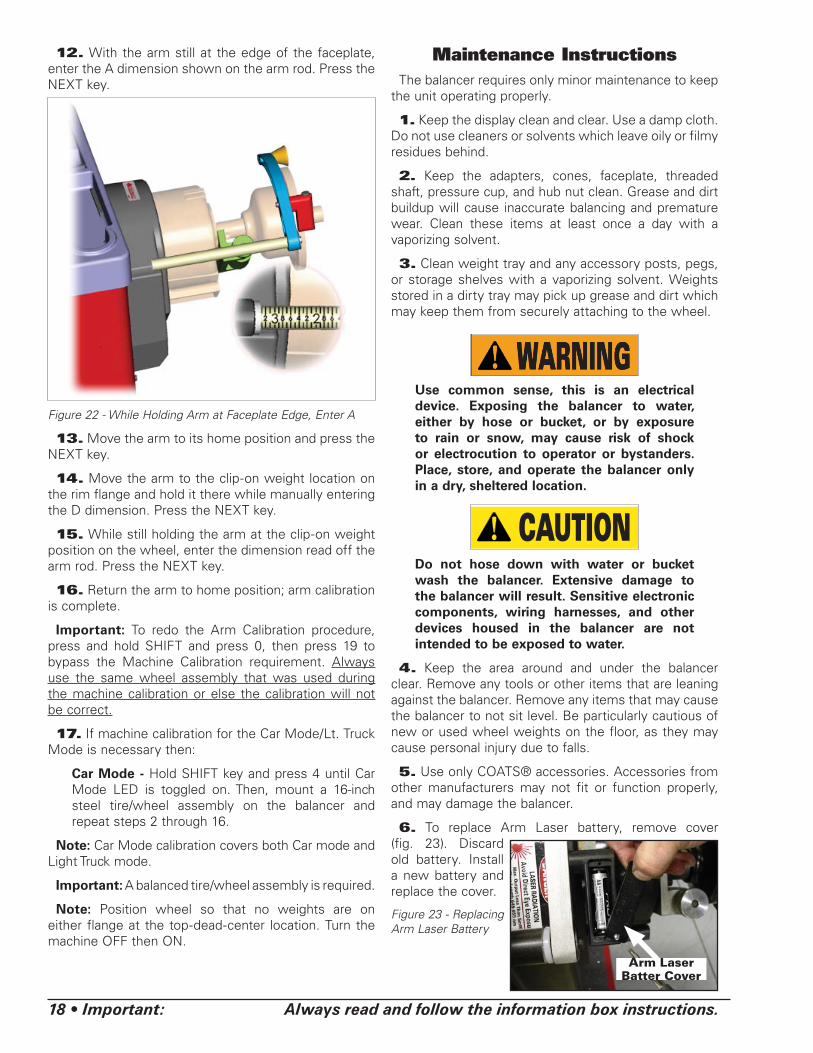
12. With the arm still at the edge of the faceplate, enter the A dimension shown on the arm rod. Press the NEXT key.
Figure 22 - While Holding Arm at Faceplate Edge, Enter A
13. Move the arm to its home position and press the NEXT key.
14. Move the arm to the clip-on weight location on the rim flange and hold it there while manually entering the D dimension. Press the NEXT key.
15. While still holding the arm at the clip-on weight position on the wheel, enter the dimension read off the arm rod. Press the NEXT key.
16. Return the arm to home position; arm calibration is complete.
Important: To redo the Arm Calibration procedure, press and hold SHIFT and press 0, then press 19 to bypass the Machine Calibration requirement. Always use the same wheel assembly that was used during the machine calibration or else the calibration will not be correct.
17. If machine calibration for the Car Mode/Lt. Truck Mode is necessary then:
Car Mode - Hold SHIFT key and press 4 until Car Mode LED is toggled on. Then, mount a 16-inch steel tire/wheel assembly on the balancer and repeat steps 2 through 16.
Note: Car Mode calibration covers both Car mode and Light Truck mode.
Important: A balanced tire/wheel assembly is required.
Note: Position wheel so that no weights are on either flange at the top-dead-center location. Turn the machine OFF then ON.
Maintenance InstructionsThe balancer requires only minor maintenance to keep
the unit operating properly.
1. Keep the display clean and clear. Use a damp cloth. Do not use cleaners or solvents which leave oily or filmy residues behind.
2. Keep the adapters, cones, faceplate, threaded shaft, pressure cup, and hub nut clean. Grease and dirt buildup will cause inaccurate balancing and premature wear. Clean these items at least once a day with a vaporizing solvent.
3. Clean weight tray and any accessory posts, pegs, or storage shelves with a vaporizing solvent. Weights stored in a dirty tray may pick up grease and dirt which may keep them from securely attaching to the wheel.
Use common sense, this is an electrical device. Exposing the balancer to water, either by hose or bucket, or by exposure to rain or snow, may cause risk of shock or electrocution to operator or bystanders. Place, store, and operate the balancer only in a dry, sheltered location.
CAUTIONDo not hose down with water or bucket wash the balancer. Extensive damage to the balancer will result. Sensitive electronic components, wiring harnesses, and other devices housed in the balancer are not intended to be exposed to water.
4. Keep the area around and under the balancer clear. Remove any tools or other items that are leaning against the balancer. Remove any items that may cause the balancer to not sit level. Be particularly cautious of new or used wheel weights on the floor, as they may cause personal injury due to falls.
5. Use only COATS® accessories. Accessories from other manufacturers may not fit or function properly, and may damage the balancer.
6. To replace Arm Laser battery, remove cover (fig. 23). Discard old battery. Install a new battery and replace the cover.
Figure 23 - Replacing Arm Laser Battery
Arm Laser Batter Cover

Important: Always read and follow the information box instructions. • 19
Diagnostic ProceduresAfter Balance Vibration Problems
If vibration is still present after balancing the wheels and driving the vehicle on smooth pavement, remove the wheels and recheck the balance. If a wheel is out of balance the cause maybe:
• Wheel was not mounted/centered correctly on the balancer.
• A weight has come off the wheel (possibly the wrong clip style). Remove the other weights from the wheel and rebalance.
• Foreign material inside the tire. Remove the tire from the wheel, remove the foreign material, and remount. Remove wheel weights and rebalance the wheel.
• Stones or other foreign objects caught in the tire tread or rim. Remove the objects. Check and rebal-ance if needed.
If the balancer still indicates the wheels are balanced to within 0.01 ounces on both inner and outer displays, the problem is not in the balance of the wheels. Check the following possible sources of vibration:
• Tire pressure. Bring all tires up to the recommended PSI.
• Radial or lateral runout in the tire or wheel. Replace the damaged part.
• Unbalance in wheel covers or trim rings. Remove the wheel covers or trim rings and test drive. If the vibration is gone, remove the shaft and use an appropriate adapter to mount the wheel to the balancer. Balance the wheel with the wheel cover or trim ring attached to the wheel.
• Incorrectly mounted tire and wheel. Remount cor-rectly.
• Damaged wheel bolt holes. Replace wheel.
• Worn universal joints. Replace as required.
• Drive shaft unbalance or damaged. Balance, repair, or replace.
• Unbalance in brake rotor(s) or drum(s).
• Suspension out of alignment. Align the vehicle and replace any damaged or worn parts.
TroubleshootingA COATS® Service Technician may ask for informa-
tion to help diagnose service concerns (Please contact COATS® directly at 1-800-688-9240 for the Certified Service Partner nearest you). Conveying this informa-tion to your service technician prior to servicing can help to expedite service to your equipment. Although much of the diagnostic information aids your COATS® Service Technician, several remedies for balancer mal-function are available to the operator.
Error Messages - One of the following error mes-sages, shown in the information box display, may appear indicating a problem with the balancer.
Note: Always EXIT error message and repeat function to see if error is eliminated.
Error 1 - Spin up is too slow - Verify power supply to balancer and motor connection E1
Error 2 - Spin up time too long - Check Wheel DIA and power supply - press STOP - EXIT E2
Error 3 - No rotation signal - Check motor & encoder function & wiring -press STOP - EXIT E3
Error 4 - Wheel rotation direction is reversed - Disconnect power and correct wiring E4
Error 5 - Stop time too long - Verify power supply and motor connection - press STOP - EXIT E5
Error 6 - Encoder is not connected or has failed - Disconnect power supply and repair E6
Error 9 - Wheel coast speed is too slow E9
Error 11 - User cancelled the operation E11
Error 20 - Arm Scale is out of range E20
Error 24 - Lower hood to spin E24
Error 25 - Loose hub nut. Tighten hub nut and respin E25
Error 26 - CAL ERROR E26
Inverter Error - Inverter Fault-Please Wait....
An inverter error occurs when one of several fault conditions is detected by the inverter; such as, low line voltage, motor over temperature, motor overload or motor drive over temperature. The balancer will not respond to inputs until the fault condition is corrected. The balancer will clear this error as soon as possible and indicate that with the following message:
Inverter Fault Cleared. Press Any Key

20 • Important: Always read and follow the information box instructions.
Installation InstructionsReceiving
The shipment should be thoroughly inspected as soon as it is received. The signed bill of lading is acknowl-edgement, for the carrier, of receipt in good condition of the shipment covered by our invoice.
If any of the goods called for on this bill of lading are shorted or damaged, do not accept them until the car-rier makes a notation of the shorted or damaged goods on the freight bill. Do this for your own protection.
NOTIFY THE CARRIER AT ONCE if any hidden loss or damage is discovered after receipt and request him to make an inspection. If the carrier will not do so, prepare an affidavit to the effect that you have so notified the carrier (on a certain date) and that he has failed to com-ply with your request.
IT IS DIFFICULT TO COLLECT FOR LOSS OR DAM-AGE AFTER YOU HAVE GIVEN THE CARRIER A CLEAR RECEIPT.
File your claim with the carrier promptly. Support your claim with copies of the bill of lading, freight bill, invoice, and photographs, if possible.
Although COATS responsibility ceases upon delivery of the shipment to the carrier, we will gladly assist in tracing lost shipments. Our willingness to assist in every possible manner does not make COATS respon-sible for collection of claims, or replacement of lost or damaged materials.
Electrical RequirementsSee serial tag for the appropriate power requirements
of your machine.
Always have a qualified electrician install the proper receptacles in accordance with state and local codes.
Setup
CAUTIONDo not use the control panel, control panel base, accessory storage, faceplate, hood or shaft to lift the balancer.
CAUTIONDo not attempt to install and setup the unit yourself. Contact COATS® as noted below.
A factory trained COATS® Service Technician must perform the install, setup, and initial test procedures on your wheel balancer. Do not attempt to install and setup the unit yourself. Accurate and reliable operation of your unit depends on proper installation. Please contact COATS® directly at 1-800-688-9240 for the Certified Service Partner nearest you.
Connect to PowerYour factory trained COATS® Service Technician should
do the final check to verify the power installation before connecting the balancer to a power supply. Failure due to improper power connection may void the warranty.
Floor and Space RequirementsThe balancer must be located on a flat floor of solid
construction, preferably concrete. The balancer must sit solidly on its three feet. If the balancer is not level, does not sit solidly on its three feet, or is placed on an unstable floor, the balancer will not function properly and may produce inaccurate balance readings.
Do not operate the balancer while it is on the pallet.
Select a location for the balancer that provides a level, solid floor, and adequate clearance around and above the balancer. Make sure the location selected has enough room above and behind the unit so the hood can be raised completely. The location must also pro-vide working room for mounting and removing wheels. Make sure the area has adequate lighting.
Figure 23 - Space Requirements
62 in.70 in.
89 in.
Important: Always read and follow the information box instructions. • 21
Specifi cationsWheel Diameter Range
19.5 - 30 inches
Wheel Width Range6 - 20 inches
Maximum Outside Tire DiameterUp to 52 inches
Maximum Tire/Wheel Weight500 pounds (227 Kg)
Mounting Shaft Diameter2.0 inches (51mm)
Resolution0.35 degrees
Balancing Display Increments2.00 or 0.01 ounces
Electrical Requirements230V ±10%, 1 Ph, 50/60 Hz, 20 amp, L6-20230V ±10%, 3 Ph, 50/60 Hz 20 amp, L15-20(use grounding type plug)
Footprint62 inches x 70 inches
Shipping Weight1.100 pounds (500 Kg)
Features• Automatic Data Entry for Offset and Diameter -
Manual Entry Backup on all Parameters
• Static-on-Screen™
• Four Fixed Function Keys, Seven Program Keys for user Friendly Operation
• Direct Select™ Weight Placement Location
Dynamic (Standard): Clip-on Weights
Alloy: User Defined
Static
Patch (Tire Weight): Static Only
• Behind the Spoke Weight Placement
• Automatic Start When Hood is Lowered
• Single Spin Balancing - Dynamic and Static
• Easy-To-Read Position Indicators
• Laser Guided Operation™ Tape-A-Weight®
• Hood Safety Interlock System
• Extended Mounting Faceplate for Deeper Wheels
• Match Balance (Optimization)
• Operator Memory for Two Different Users
• User Friendly Weight Calibration
• No Bolt-down Installation
• Digital Motor Control
• Automatic Stop & Lock
• Automatic Indexing
• MET Lab Listing

85606875 03 01/2017 © Copyright 2010 Hennessy Industries and COATS® All Rights Reserved. Printed in USA