Embed Size (px)
Citation preview

OM 480989011-0515-A
8406H HW W/HORNOWNERS MANUAL
Serial No. __________________
Mailing Address: P.O. Box 580697 Tulsa, OK 74158-0697 Physical Address: 4707 N. Mingo Rd. Tulsa, OK 74117-5904
Phone 1-800-777-2760 Fax (918) 269-6688 http://www.autocrane.com


Product Registration Rev 05152014
Auto Crane Registration
From: Date:
End User Information:
Company: Phone:
Address:
City: State: Zip:
Contact: E-mail:
Distributor Information:
Company: Phone:
Address:
City: State: Zip:
Contact: E-mail:
Product Information:
Model No: Serial No: Date Delivered:
VIN #:
ONE REGISTRATION FORM PER UNIT (CRANE, BODY, OR COMPRESSOR)Please submit form within 15 days after installation
Online: www.autocrane.com | Resources | Warranties
Fax: 918-234-2177
Mail: Product Registration, Auto Crane Company, PO Box 580697, Tulsa, OK 74158-0697

Notes:
1. The information contained in this manual is in effect at the time of this printing. It does not
cover all instructions, configurations, accessories, etc. If you require ad ditional information,
please contact Auto Crane Company at 1-800-777-2760.
2. Auto Crane Company reserves the right to update this material without notice or obligation.

WARNINGS WARNING! Federal law (49 cfr part 571) requires that the Final Stage Manufacturer of a vehiclecertify that the vehicle complies with all applicable federal regulations. Any modifications performed on the vehicle prior to the final state are also considered intermediate stage manufacturing and must be certified as to compliance. The installer of this crane and body is considered one of the manufacturers of the vehicle. As such a manufacturer, the installer is responsible for compliance with all applicable federal and state regulations, and is required to certify that the vehicle is in compliance.
WARNING! It is the further responsibility of the installer to comply with the OSHA Truck Crane Stability Requirements as specified by 29 CFR part 1910.180 (C) (1).
WARNING! NEVER OPERATE THE CRANE NEAR ELECTRICAL POWER LINES! Death or serious injury will result from boom, line, or load contacting electric lines. Do not use crane within 10 feet (3.05m) of electric power lines carrying up to 50,000 volts. One-foot additional clearance is required for every additional 30,000 volts or less. SEE DANGER DECAL (P/N 040529) in this Owner's Manual.
WARNING! NEVER......................................... EXCEED load chart capacities (centerline of rotation to hoist hook).Un-reel last 5 wraps of cable from drum!Wrap cable around load!Attempt to lift or drag a load from the side! The boom can fail far below its rated capacity.Weld, modify, or use unauthorized components on any Auto Crane unit! This will void any warranty or liability. Also failure of the crane may result.Place a chain link on the tip of the hook and try to lift a load!Use a sling bar or anything larger than the hook throat that could prevent the hook latch from closing, thus negating the safety feature!Hold on any pendant Select Switch that will cause unsafe operating conditions!
WARNING! In using a hook with latch, ALWAYS make sure that the hook throat is closed before lifting a load! Proper attention and common sense applied to the use of the hoist hook and various slings will prevent possible damage to material being hoisted and may prevent injury to personnel.
WARNING! Failure to correctly plumb and wire crane can cause inadvertent operation and damage to crane and/or personnel!
WARNING! Auto Crane Company remote controlled cranes are not designed or intended for use for any applications involving the lifting or moving of personnel.
WARNING! ALWAYS operate the crane in compliance with the load capacity chart. DO NOT USEthe overload shutdown device to determine maximum rated loads, if the crane is equipped with this type of device.
READ THIS PAGE

7
8406H HW W/HORN
TABLE OF CONTENTS
INTRODUCTION 1
GENERAL SPECIFICATIONS 3
SAFETY TIPS AND PRECAUTIONS 4
OPERATING PRACTICES & WARNINGS 6
QUALIFICATIONS FOR OPERATORS 7
OPERATION OF UNIT I OUTRIGGERS 10
CRANE OPERATION 11
TRANSMITTER INSTRUCTIONS 14
INSPECTION 15
TESTING 17
GENERAL MAINTENANCE 18
BATTERIES 20
LUBRICATION AND MAINTENANCE SCHEDULE 22
SAFETY DECAL SECTION 25
GENERAL DIMENSIONS 30
MOUNTING AND INSTALLATION 31
GENERAL ASSEMBLY 34
PEDESTAL ASSEMBLY 36
BOOM ASSEMBLY 40
ROTATION GEARBOX 42
HOIST ASSEMBLY 44
TRAVELING BLOCK ASSEMBLY 47
ELECTRICAL SCHEMATIC 48
MAIN WIRING HARNESS 49
JUNCTION BOX 51
PENDANT ASSEMBLY 53
HYDRAULIC SECTION 56
COUNTERBALANCE VALVE 59
VALVE OVERRIDE OPERATION 60
LOAD CHART 61
WARRANTY LAST PAGE

1
8406H HW W/HORN
INTRODUCTION
alternator with a 500 cold cranking amp battery. These specifications should be considered minimum.
It has always been Auto Crane Company policy to handle all warranty claims we receive as promptly as possible. If a warranty claim involves discrepant material or workmanship, Auto Crane will take immediate correctiveaction. It is understandable that Auto Crane Company cannot assume responsibility of liability when it is obvious that our products have been abused, misused, overloaded or otherwise damaged by inexperienced persons trying to operate the equipment without reading the manual.
Auto Crane maintains a strong distributor network and a knowledgeable Customer Service Department. In most cases, an equipment problem is solved via phone conversation with our customer service department. The customer service department also has the ability to bring a local distributor, a regional sales manager, or a factory serviceman into the solution of an equipment problem.
If, through no fault of Auto Crane Company, it is necessary to send an experienced factory serviceman on a field service call the rates stated in the Auto Crane Distributor's Flat Rate Manual will apply.
Auto Crane Company's extensive Research and Development Program allow our customers to use the best equipment on the market. Our Engineering Staff and our knowledgeable sales people are always available to our customers in solving crane and winch-type application problems. When in doubt, call the Auto Crane factory.
Auto Crane will not assume responsibility or liability for any modifications or changes made to unit, or installation of component parts without authorization.
Note: This manual should remain with the crane at all times.
Auto Crane products are designed to provide many years of safe, trouble-free, dependable service when properly used and maintained.
To assist you in obtaining the best service from your crane and to avoid untimely crane and/or vehicle failure, this manual provides the following operating and service instructions. It is specifically recommended that all operating and service personnel consider this manual as mandatory material for reading and study before operating or servicing Auto Crane products. It is highly recommended that crane owners, equipment managers, and supervisors also read this manual.
Auto Crane has incorporated several safety features in the 8406H HW W/HORN crane for your protection.
For your convenience the overall dimensionsof the 8406H crane are included General Dimension Drawing. Rotation
turning radius are also listed on the drawing.
Remember, the crane adds weight to the vehicle. Adding weight may change the driving and riding characteristics of the vehicle unless the appropriate overload spring(s) are installed on the truck. The payload of the vehicle is reduced by the weight of the crane. The operator should exercise care when loading the vehicle. Distributing the payload on the vehicle evenly will greatly improve the driving and riding characteristics of the vehicle.
The 8406H HW W/HORN cranes are attached to your 12-volt truck electrical system through the relay provided. The 8406H HW W/HORN is another highly efficient Auto Crane product. The use of a maintenance-free battery is not recmmended on any Auto Crane product. The recommended alternator and battery that will give the longest life with the most useful duty cycle is a 60-amp
Auto Crane Company issues a limited warranty certificate with each unit sold. See last page for warranty.

2
DISTRIBUTOR ASSISTANCE:
Should you require any assistance not given in this manual, we recommend that you consult your nearest Auto Crane Distributor. Our distributors sell authorized parts and have service departments that can solve almost any needed repair. This manual does not cover all maintenance, operating, or repair instructions pertinent to all possible situations. If you require additional information, please contact the Auto Crane Company at the following tele-phone number: 1-800-777-2760. Theinformation contained in the manual is in effect at the time of this printing. Auto Crane Company reserves the right to update this material without notice or obligation.
8406H HW W/HORN
INTRODUCTION

3
GENERAL SPECIFICATIONS
8406H HW W/HORN

4
1. No unqualified or unauthorized person shall be allowed to operate the crane.
2. WARNING: Never weld, modify, or use unau-thorized components / parts on any Auto Crane unit. This will void any warranty or liability. Also, failure of the crane may result.
3. Make certain the vehicle meets minimum chassis requirements. (These requirements do not guarantee unit stability.)
4. Make certain the crane is installed per factory specifications. Contact your local distributor or the Auto Crane factory if any questions arise.
5. Visual inspections and tests should be con-ducted at the beginning of each shift each day to insure that the crane and all its operat-ing systems are in good condition and work-ing order before it is used.
6. Inspect hydraulic hoses frequently for signs of deterioration, and replace them as re-quired.
7. If a hydraulic break occurs, leave the area of the break and do not attempt to stop the break by hand as the hydraulic oil may be hot and under high pressure which can cause serious injury. Shut the system down as soon as possible.
8. Check the hook at least every thirty days for distortions or cracks and replace it as re-quired.
9. Oil gears as required.
10. Stop all operations when cleaning, adjusting or lubricating the machine.
11. Keep dirt and grit out of moving parts by keeping crane clean. Make sure machine is free of excess oil, grease, mud and rubbish, thus reducing accidents and fire hazards.
12. When a new cable is installed, operate first with a light load to let the cable adjust itself.
13. Locate the vehicle at the work site for the best stability possible.
14. Keep the vehicle in a level position while loading or unloading.
15. Observe operating area for obstructions and/or power lines that might be a hazard.
16. WARNING: NEVER OPERATE THE CRANE NEAR ELECTRICAL POWER LINES. Auto Crane Company recommends that the crane never be any closer to a power line (including telephone lines) than 10 feet at any point.
17. Allow the vehicle engine to warm up before operating crane.
18. Know the weight of your rigging and load to avoid overloading the crane.
19. Deduct the weight of the load handling equip-ment from the load rating to determine how much weight can be lifted.
20. All load ratings are based on crane capacity, NOT the vehicle stability. Remember in lifting a heavy load, the weight can create enough tipping moment to overturn the vehicle
21. Always comply with load chart capacities, (centerline of rotation to hook).
22. Secure all loads before lifting.
23. Always set the emergency brake before begin-ning operation.
24. Keep objects and personnel clear of crane path during operation.
25. Operate control levers slowly and smoothly in order to meter oil flow for safe operation. (Not applicable to electric-hydraulic cranes.)
26. Always extend the outriggers from vehicle to the ground before crane operation. Insure that they are firmly positioned on solid foot-ings. Stand clear of outriggers while they are being extended.
27. If any outrigger, when extended, rests on a curb or other object that prevents it from ex-tending to its maximum distance, shorten bearing or fulcrum point and reduce the maxi-mum load accordingly.
28. When an outrigger will not reach the ground due to holes or grades, it shall be blocked up to provide level and firm support for the truck.
29. When working in soft earth, use wide pads under outrigger feet to prevent sinking.
30. Always store outriggers before transportation.
WARNING!Auto Crane Company cranes are not designed or intended for use in lifting or moving persons. Any such use shall be considered to be improper and the seller shall not be responsible for any claims arising there from. This sale is made with the express understanding that there is no warranty that the goods shall be fit for the purpose of lifting or moving persons or other improper use and there is no implied warranty or responsibility for such purposes.
— IMPORTANT—
SAFETY TIPS AND PRECAUTIONS

5
31. Always store the crane in its stowed position for transportation.
32. Remember the overall height of the entire unit for garage door clearance or when moving under objects with low overhead clearance
33. Disengage power takeoff (PTO) before moving the vehicle. (Not applicable to electric-hydraulic cranes.)
34. Always walk around the vehicle before moving.
35. Never drive with a load suspended from crane.
36. Do not take your eyes off a moving load. Look in the direction you are moving.
37. Never swing a load over people.
38. Do not stop the load sharply in midair so that it swings like a pendulum. Meter the control levers to avoid this situation. (Not applicable to electric-hydraulic cranes.)
39. Crane boom length should be kept as short as possible for maximum lifting capacity and greater safety. Longer booms require addi-tional care in accelerating and decelerating the swing motion, and thus slow down the working cycle and reduce productivity.
40. Keep the load directly and vertically under the boom point at all times. Crane booms are designed to handle vertical loads, not side lifts.
WARNING: Never attempt to lift, drag, tow or pull a load from the side. The boom can fail far below its rated capacity.
41. Do not push down on anything with boom extensions; similarly do not lift anything with boom extensions.
42. Do not lift personnel with any wire rope at-tachment or hook. There is no implied war-ranty or responsibility for such purposes.
43. WARNING: In using a safety hook, ALWAYS close the hook throat before lifting a load. Proper attention and common sense applied to the use of the hook and various slings will prevent possible damage to material being hoisted and may prevent injury to personnel.
44. WARNING: Never place a chain link on the tip of the hook and try to lift a load with the hoist.
45. WARNING: Never use a sling bar or anything larger than the hook throat which could pre-vent the safety latch from closing, thus negat-ing the safety feature.
46. Do not wrap the wire rope around sharp ob-jects when using winch.
47. WARNING: Never unreel last 5 wraps of ca-ble from drum.
— IMPORTANT—
SAFETY TIPS AND PRECAUTIONS

6
1. Make certain the vehicle meets minimum chassis requirements. (These requirements do not guarantee unit stability)
2. Make certain the crane is installed per factory specifications. Contact your local Distributor or the Auto Crane factory if any questions arise.
3. Keep the vehicle in as level a position as possible while loading or unloading.
4. ALWAYS set the vehicle emergency brake before beginning crane operations.
5. ALWAYS use outriggers from vehicle to the ground during crane operation. Make sure they are firmly positioned on solid footings.
6. All load ratings are based on crane capacity, NOTtruck/crane stability.
7. Keep objects and personnel clear of crane path during operation.
8. Keep hoist cable pulled tight at all times.
9. REMEMBER, in lifting a heavy load, the weight can create enough tipping momentum to overturn the vehicle.
10. ALWAYS keep load as close to ground as possible.
11. Hydraulic hoses need to be inspected frequently for signs of deterioration, and be replaced as required.
12. The hoist hook is an important item that an operator should consider and use properly. It should be checked on a daily basis for distortion or cracks.
13. ALWAYS store outriggers before road travel.
14. In applications, where the rotation of the load is haz-ardous, a tag or restraint line should be used (ref OSHA 1910.180(h)(3)(xvi)). To reduce the potential for the load to rotate or rope twist, operate at mini-mal boom angles and extension.
15. WARNING! NEVER OPERATE THE CRANE NEAR ELECTRICAL POWER LINES! Death or serious injury will result from boom, line, or load contacting electric lines. Do not use crane within 10 feet (3.05m) of electric power lines carrying up to 50,000 volts. One foot additional clearance is required for every additional 30,000 volts or less.
16. WARNING! NEVER EXCEED load chart capacities (centerline of rotation to hoist hook).
17. WARNING! NEVER un-reel last 5 wraps of cable from drum!
18. WARNING! NEVER wrap cable around load!
19. WARNING! NEVER attempt to lift or drag a load from the side! The boom can fail far below its rated capacity.
20. WARNING! NEVER weld, modify, or use unauthorized components on any Auto Crane unit! This will void any warranty or liability. Also failure of the crane may result.
21. WARNING! NEVER place a chain link on the tip of the hook and try to lift a load!
22. WARNING! NEVER use a sling bar or anything larger than the hook throat that could prevent the hook latch from closing, thus negating the safety feature!
23. WARNING! In using a hook with latch, ALWAYSinsure that the hook throat is closed before lifting a load! Proper attention and common sense ap-plied to the use of the hoist hook and various slings will prevent possible damage to material being hoisted and may prevent injury to personnel.
WARNING! NEVER hold any Control Select Switch on that will cause unsafe operatingconditions!
WARNING!
Auto Crane Company remote controlled, stiff boom cranes are not designed or intended for use on any applicationsinvolving the lifting or moving of personnel.
—IMPORTANT—
OPERATING PRACTICES AND WARNINGS

7
REFERENCE ASME B30.5a AND OSHA 1910.180 FOR COMPLETE QUALIFICATION RE-
QUIREMENTS
OPERATORS
QUALIFICATIONS FOR OPERATORS
CONDUCT OF OPERATORS
5.
QUALIFICATIONS FOR AND CONDUCT OF
OPERATORS AND OPERATING PRACTICES

8
or neutral position and all personnel are in the clear.
6. If power fails during operation, the operator shall:
A. Move power controls to the “OFF” or neu-tral position.
B. Land the suspended load and boom, if practical.
7. The operator shall be familiar with the equip-ment and its proper care. If adjustments or repairs are necessary, the operator shall re-port the same promptly to the appointed per-son, and shall also notify the next operator.
8. The operator at the start of each shift shall test all controls. If any controls do not operate properly, they shall be adjusted or repaired before operations are begun.
9. Stabilizers shall be visible to the operator while extending or setting unless a signal person assists operator.
OPERATING PRACTICES/HANDLING THE
LOAD
1. Size of load.
A. No crane shall be loaded beyond the rated load except for test purposes
B. The load to be lifted is to be within the rated load of the crane and its existing configuration.
C. When loads that are not accurately known are to be lifted, the person responsible for the job shall ascertain that the weight of the load does not exceed the crane rated load at the radius at which the load is to be lifted.
2. Attaching the load.
A. The load shall be attached to the hook by means of slings or other devices of sufficient capacity.
B. Hoist rope shall not be wrapped around the load.
3. Moving the load.
The operator shall determine that:
A. The crane is level and, where necessary, the vehicle/carrier is blocked properly.
B. The load is well secured and balanced in the sling or lifting device before it is lifted more than a few inches.
C. Means are provided to hold the vehicle stationary while operating the crane.
D. Before starting to lift, the hook shall be positioned over the load in such a manner as to minimize swinging.
E. During lifting care shall be taken that:
1. There is no sudden acceleration or deceleration of the moving load.
2. Load, boom or other parts of the crane do not contact any obstruction.
F. Cranes shall not be used for dragging loads sideways.
G. This standard recognizes that telescopic boom cranes are designed and intended for handling materials. They do not meet personnel lift or elevator requirements. Therefore, no lifting, lowering, swinging or traveling shall be done while a person is on the hook or load. Hook attached suspended work platforms (baskets) shall not be used with cranes covered by this standard. Crane manufacturer must approve work platforms attached to the boom.
H. The operator should avoid carrying loads over people.
I. When the crane is so equipped, the stabilizers shall be fully extended and set. Blocking under stabilizers shall meet the requirements as follows:
1. Strong enough to prevent crushing.
2. Of such thickness, width and length as to completely support the stabilizer pad.
J. Firm footing under all tires, or individual stabilizer pads should be level. Where such a footing is not otherwise supplied, timbers, cribbing, or other structural members to distribute the load so as to not exceed allowable bearing capacity or the underlying material should provide it.
K. In transit, the boom shall be carried in stowed position.
L. When rotating the crane, sudden starts and stops shall be avoided. Rotational speed shall be such that the load does not swing out beyond the radius at which it can be controlled.
M. The crane shall not be transported with a load on the hook unless recommended by the manufacturer.
QUALIFICATIONS FOR AND CONDUCT OF
OPERATORS AND OPERATING PRACTICES

9
2-6.0
N. No person should be permitted to stand or pass under a suspended load.
4. Stowing procedure.
Follow the manufacturer's procedure and sequence when stowing and un-stowing the crane.
MISCELLANEOUS
OPERATING NEAR ELECTRICAL POWER
LINES
1. Cranes shall be operated so that no part of the crane or load enters into the danger zone shown above.
EXCEPTIONS
A. The danger zone may be entered after confirmation by an appointed person that the electrical distribution and transmis-sion lines have been de-energized and visibly grounded at the point of work; or
B. The danger zone may be entered if insu-lating barriers (not a part of nor an at-tachment to the crane) have been erected to prevent physical contact with the lines.
2. For lines rated 50 kV or below, minimum clearance between the lines and any part of the crane or load (including handling ap-pendages) shall be 10-ft. (3m). For higher voltages, see Table 1.
3. Caution shall be exercised when working near overhead lines, because they can move horizontally or vertically due to wind, moving the danger zone to new positions.
4. In transit with no load and boom lowered the clearance shall be specified in Table 1.
5. A qualified signalperson shall be assigned to observe the clearance and give warning before approaching the above limits.
A. Any overhead wire shall be considered to be an energized line unless and until the person owning such line or the electrical utility authorities verify that it is not an energized line.
B. Exceptions to this procedure are allowed, if approved by the administrative or regulatory authority provided the alternate procedure insures equivalent protection and is set forth in writing.
C. Durable signs shall be installed at the operator's station and on the outside of the crane, warning that electrocution or serious bodily injury may occur unless a minimum clearance of 10 ft. (3.0m) between the crane or the load being handled and energized power lines. Greater clearances are required because of higher voltage as stated above. These signs shall be revised but not removed when local jurisdiction requires greater clearances.
QUALIFICATIONS FOR AND CONDUCT OF
OPERATORS AND OPERATING PRACTICES
10
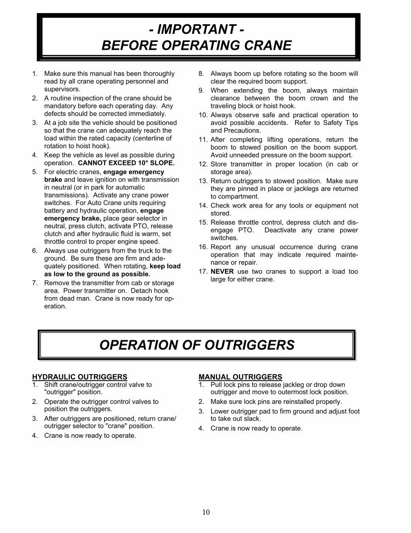
1. Make sure this manual has been thoroughly read by all crane operating personnel and supervisors.
2. A routine inspection of the crane should be mandatory before each operating day. Any defects should be corrected immediately.
3. At a job site the vehicle should be positioned so that the crane can adequately reach the load within the rated capacity (centerline of rotation to hoist hook).
4. Keep the vehicle as level as possible during
operation. CANNOT EXCEED 10° SLOPE.
5. For electric cranes, engage emergency brake and leave ignition on with transmission in neutral (or in park for automatic transmissions). Activate any crane power switches. For Auto Crane units requiring battery and hydraulic operation, engage emergency brake, place gear selector in neutral, press clutch, activate PTO, release clutch and after hydraulic fluid is warm, set throttle control to proper engine speed.
6. Always use outriggers from the truck to the ground. Be sure these are firm and ade-quately positioned. When rotating, keep load
as low to the ground as possible.
7. Remove the transmitter from cab or storage area. Power transmitter on. Detach hook from dead man. Crane is now ready for op-eration.
8. Always boom up before rotating so the boom will clear the required boom support.
9. When extending the boom, always maintain clearance between the boom crown and the traveling block or hoist hook.
10. Always observe safe and practical operation to avoid possible accidents. Refer to Safety Tips and Precautions.
11. After completing lifting operations, return the boom to stowed position on the boom support. Avoid unneeded pressure on the boom support.
12. Store transmitter in proper location (in cab or storage area).
13. Return outriggers to stowed position. Make sure they are pinned in place or jacklegs are returned to compartment.
14. Check work area for any tools or equipment not stored.
15. Release throttle control, depress clutch and dis-engage PTO. Deactivate any crane power switches.
16. Report any unusual occurrence during crane operation that may indicate required mainte-nance or repair.
17. NEVER use two cranes to support a load too large for either crane.
OPERATION OF OUTRIGGERS
HYDRAULIC OUTRIGGERS1. Shift crane/outrigger control valve to
"outrigger" position.
2. Operate the outrigger control valves to position the outriggers.
3. After outriggers are positioned, return crane/outrigger selector to "crane" position.
4. Crane is now ready to operate.
MANUAL OUTRIGGERS1. Pull lock pins to release jackleg or drop down
outrigger and move to outermost lock position.
2. Make sure lock pins are reinstalled properly.
3. Lower outrigger pad to firm ground and adjust foot to take out slack.
4. Crane is now ready to operate.
- IMPORTANT -
BEFORE OPERATING CRANE

11
TRANSMITTER LAYOUT
E-STOP SWITCH
MECHANICAL LATCHING
(TWIST TO UNLOCK)
25% 50% 75% 100%
ON/OFF/MULTI SPEED
3 POSITION KEYSWITCH
LED INDICATORS
E-stop Switch—Push to activated, Twistto release. Shuts down all outputs from receiver.
On/Off/Multispeed— Detachable key, On, Off, Multispeed, & Start Switch.
BOOM DOWN BOOM UP
Crane Controls—Proportional push button. The function speed increasesthe more the button is pressed.
ROTATE CW
HOIST DOWN
BOOM RETRACT
ROTATE CCW
HOIST UP
BOOM EXTEND
Functions include Boom Up/Down, Rotate CW-CCW, Hoist Up/Down, BoomExtend, Retract.
Engine Fast-idle (Nexstar II Only) -Activates Fast Idle on Vehicle. (Can be latching or momentary)
ENGINE FAST IDLE
(NEXSTAR II ONLY)
ENGINE STOP
(NEXSTAR II ONLY)
FAST
IDLEAUX
AUXILIARY
(NEXSTAR II ONLY)
ENGINE START
(NEXSTAR II ONLY)
Auxiliary (Nexstar II Only) - Sends a latched signal that activates an auxiliary output to operate an external component i.e. compressor, worklights. (Must use a relay to separate auxiliary crane circuit and external component.)
ENG ENG
STOP STARTEngine Stop (Nexstar II Only) - Sends a momentary signal from crane to shut down vehicle.
Engine Start (Nexstar II Only) - Sencs a momentary signal from crane to start vehicle.
BELT CLIP
TURNING OFF TRANSMITTER— Move the On/Off/Multi-speed switch to the “off” position
TURNING ON TRANSMITTER— Move the On/Off/Multi-speed switch to the “on” position, wait 3 seconds. Thenmove the On/Off/ Multi-speed switch to the “Multi-speed” or “start” position momentarily. The status light shouldbe blinking green when active with no buttons depressed.
REMOVING KEY— Move the On/Off/Multi-speed switch to the “off” position, then move the switch counter-clockwise one position past the “off” position. Once the switch is one position past the “off” position then pull out the switch from the transmitter.
CRANE OPERATION

12
E-STOP SWITCH
MECHANICAL LATCHING
(TWIST TO UNLOCK)
ON/OFF/MULTI SPEED
3 POSITION KEYSWITCH
LED INDICATORS
DECREASE MAX
SPEED
25% 50% 75% 100%
INCREASE MAX
SPEED
ACTIVATING E-STOP
Press the E-stop Switch.
Note:1. When E-stop is active, the transmitter will remain on but will not operate any functions. This includes truck
and crane functions.2. Activating E-stop will not turn the truck off.3. There will be an Error Code on the receiver stating “E-stop active”.
DEACTIVATING E-STOP
1. Twist to release E-stop.2. Turn transmitter to the “OFF” position.3. Once all lights turn off. Turn transmitter to the “ON” position.4. Wait 3 seconds and then turn transmitter to the “START”/”SPEED” position and release
Note:There is very little height difference in a active and inactive E-stop. To verify E-stop switch is deactivated, twist switch to release.
WAKING UP TRANSMITTER
Turn the transmitter to the “START”/”SPEED” position and release
Note:The transmitter goes into sleep mode after 5 minutes of inactivity. All truck functions are still available and will remain in the same state. (i.e. Aux function will remain on even when the unit goes to sleep if it was active before unit went to sleep.)
SPEED CONTROL
1. Rotate “ON/OFF/SPEED” switch to the “SPEED” position and hold2. Press the Boom Up switch in increase max speed or press Boom Down button to decrease. Each time the
button is actuated, the max speed increases or decreases to the next 25% range.3. Release “ON/OFF/SPEED” switch once the desired speed is selected.
Note:1. Slower speed decreases the max speed and gives more finite control of the proportional push button.2. Faster speed increases the max speed but give less finite control of the load3. The LED indicators show the current speed setting of the transmitter.
CRANE OPERATION

13
RECEIVER LAYOUT
CRANE STATUS—shows current status of the crane. If any alarms are occurring they will be displayed here. Otherwise, it will say system good. Note: Reference Troubleshooting section for alarm descriptions.
LIFT CYLINDER PRESSURE—Current pressure in the lift cylinder in PSI
FUNCTION ACTIVATED SP-SPEED PERCENT—Current function activated and percent of max speed for that particular function. Note: If multi-functioning, only last function selected will be displayed.
HIGH IDLE ACTIVE—Shown only when the high idle function is active (Nexstar II Only)
BOOM ANGLE (DEGREES) - Current boom angle in degrees. Note this value may not match the boom angle decal attached to side of boom since the decal is referenced to the ground not the pedestal.
BOOM LOAD—Current percent of crane capacity used. Note: Unloaded this value may be higher than 0% due to boom weight beyond the retracted position.
ACTIVE SIGNALS FROM TRANSMITTER—Shows current status of transmitter. 0 means the transmitter is not active. It must be turned on, e-stop deactivated, or taken out of sleep mode. 5-6 means the transmitter is active but no function is currently being selected. Receiver is waiting on a command from the user. 9-10 means the transmitter is sending crane function signals to start operating the crane. The user is sending a command for the crane to operate.
TRANSMITTER SIGNAL STRENGTH—Shows the strength of signal coming from transmitter. Note: approx. distance of transmitter is 300 feet.
BATTERY LIFE—Percent of transmitter battery life remaining
WATCH DOG TIMER— Should always be spinning. If timer stops spinning contact your AutoCrane representative
ENGINE START/STOP—Shows when the Engine Start or Engine Stop button is being selected. Should only be visible when the corresponding button is being depressed. (Nexstar II Only)
AUXILIARY ACTIVE— Shows when the auxiliary function is active. (Nexstar II Only)
80%9
CRANE STATUS
HIGH IDLE ACTIVE
BOOM ANGLE (DEGREES)
BOOM LOAD
(% OF TOTAL LOAD)
TRANSMITTER SIGNAL
STRENGTHBATTERY LIFE
% LEFT
100%
WATCH DOG
TIMER
FUNCTION ACTIVATED
SP - SPEED PERCENT
ENGINE START (ENG ON) OR
ENGINE STOP (ENG OFF)
ACTIVE
SYSTEM GOODBoom Pressure 174Boom Down SP=100%HIGH IDLE AUX ENG XXXBoom Angle 43 (deg)Boom Load 7%
AUXILIARY ACTIVE
ACTIVE SIGNALS
FROM TRANSMITTER
LIFT CYLINDER
PRESSURE
CRANE OPERATION

14
1. The receiver must be shut off and powered down The current address tag must be removed from the harness and the LEARN tag (366823955) will need to be put in its place.
2. After the LEARN tag has been put into place and the receiver is powered up, it will begin to search for the proper Channel and Serial Number of the transmitter. Note: The transmitter must be powered up and the start/speed button must be held in the “speed” position. Make sure the transmitter is blinking the
amber led in the center. Reference figure 1 below for LCD screen display during this step. Reference figure 2 below for transmitter switch position.
Figure 1—LCD screen display during step 2 Figure 2—Transmitter Switch Position
3, The receiver will start searching to find the channel and Serial Number. Once the numbers are found, it will display it on the LCD screen and will state “Press <Function> to confirm code”. At this time, release “speed position” and press then release the function shown on the screen. In the example below , press and release the Swing Clockwise function. Reference figures below:
Figure 3—LCD screen display & transmitter during step 3
4. Once the code is confirmed, remove the LEARN tag from the harness. Then power the receiver off (main crane power switch) - reference figure 5
Figure 5—LCD screen display during step 4
5. Re-attach the crane address tag to the harness and power up receiver. Confirm all functions are operational. Note: If the LEARN tag was not removed before powering down the receiver, the new channel and
serial number will not be saved.
S0. ESTOP ACTIVELearnMode sc= 6 rf=21Cur Rx Code 010020New Rx Code 00Start transmitter for new code
100%80%9
CURRENTLY IN LEARN MODE
CURRENT SERIAL NUMBER
NEW SERIAL NUMBER
CURRENT STEP
INSTRUCTIONS
CURRENT CHANNEL BEING
SCANNED
CURRENT SET
CHANNELSPEED
OFF
ON
HOLD SWITCH IN
THIS POSITION
SHOULD BE BLINKING
AMBER
25% 75%50% 100%
100%80%9
CURRENTLY IN LEARN MODE
CURRENT SERIAL NUMBER
NEW SERIAL NUMBER
CURRENT STEP
INSTRUCTIONS
CURRENT SET
CHANNEL
CHANNEL FOR NEW
TRANSMITTER
SYSTEM GOODLearnMode sc= 7 rf=21Cur Rx Code 010020New Rx Code 01157Press Swing CW to confirm code
SPEED
ON
OFF
PRESS AND
RELEASE
THIS BUTTON
RELEASE THIS
SWITCH
100%80%9
SYSTEM GOODLearnMode sc= 7 rf=21Cur Rx Code 010020New Rx Code 01157Rx Code confirmed remove tag to save
SYSTEM GOODLearnMode sc= 7 rf=21Cur Rx Code 010020New Rx Code 01157New code saved power rcvr off
100%80%9
BEFORE TAG IS REMOVED AFTER TAG IS REMOVED
TRANSMITTER SYNCHRONIZATION
INSTRUCTIONS

15
REFERENCE ASME B30.5a AND OSHA 1910.180 FOR COMPLETE INSPECTION REQUIREMENTS
INSPECTION CLASSIFICATION
1. Initial inspection.
Prior to initial use, all new, altered, modified or extensively repaired cranes shall be inspected by a designated person to insure compliance with provisions of this standard
1. Regular inspection.
Inspection procedure for cranes in regular service is divided into two general classifications based upon the intervals at which inspection should be performed. The intervals in turn are dependent upon the nature of the components of the crane and the degree of their exposure to wear, deterioration, or malfunction. The two general classifications are herein designated as "frequent" and "periodic" with respective intervals between inspections as defined below.
A. Frequent inspection - daily or before each use
B. Periodic inspection - one to twelve-month intervals or as specifically recommended by the manufacturer or qualified person.
DESIGNATED PERSONNEL SHALL
PERFORM INSPECTIONS ONLY.
FREQUENT INSPECTION
Inspections should also occur during operation for any deficiencies that might appear between regular in-spections. Any deficiencies, such as those listed below, shall be carefully examined and a determination made as to whether they constitute a hazard:
1. Inspect control mechanisms for maladjustment that interferes with proper operation.
2. Inspect control mechanisms for excessive wear of components and contamination by lubricants or other foreign matter.
3. Inspect safety devices for malfunction.
4. Visually inspect all hydraulic hoses, particularly those that flex in normal operation of crane func-tions.
5. Inspect hooks and latches for deformation, chemi-cal damage, cracks, and wear. Refer to ANSI/ASME B30.10.
6. Inspect for proper rope reeving.
7. Inspect electrical wiring and components for malfunctioning, signs of excessive deterioration, dirt and moisture accumulation.
8. Inspect hydraulic system for proper oil level and leaks.
9. Inspect tires for recommended inflation pressure, cuts and loose wheel nuts.
10. Inspect connecting pins and locking device for wear damage and loose retaining bolts.
11. Inspect rope for gross damage, such as listed below, which may be an immediate hazard.
A. Distortion such as kinking, crushing, un-stranding, birdcaging, main strand displacement, or core protrusion. Loss of rope diameter in a short length or unevenness of outer strands should be replaced.
B. General corrosion.
C. Broken or cut strands.
D. Use care when inspecting sections of rapid deterioration around flange points, crossover points, and repetitive pickup points on drums.
E. Inspect number, distribution, and type of visible broken wires. Reference Rope Maintenance section in the owner’s manual.
Continued use of rope depends upon good judgment by a designated person in evaluating remaining strength in a used rope after allowance for deterioration disclosed by inspection. Continued rope operation depends upon this remaining strength.
PERIODIC INSPECTION
Any deficiencies, such as those listed below, shall be carefully examined and determination made as to whether they constitute a hazard:
1. Inspect for deformed, cracked or corroded members in the crane structure and entire boom.
2. Inspect for loose bolts, particularly mounting bolts.
3. Inspect for cracked or worn sheaves and drums.
4. Inspect for worn, cracked, or distorted parts such as pins, bearings, shafts, gears, rollers and devices.
5. Inspect for excessive wear on brake and clutch system parts and lining.
INSPECTION
REQUIREMENTS

16
6. Inspect crane hooks for cracks.
7. Inspect travel steering, braking, and locking devices for malfunction.
8. Inspect for excessively worn or damaged tires.
9. Inspect hydraulic hose, fittings, and tubing for the following problems:
A. Evidence of leakage at the surface of the flexible hose or its junction with metal and coupling.
B. Blistering, or abnormal deformation to the outer covering of the hydraulic or pneumatic hose.
C. Leakage at threaded or clamped joints that cannot be eliminated by normal tightening or recommended procedures.
D. Evidence of excessive abrasion or scrubbing on the outer surface of a hose, rigid tube, or fitting. Means shall be taken to eliminate the interference of elements in contact or other-wise protect the components.
10. Inspect hydraulic pumps and motors for the following problems:
A. Loose bolts and fasteners.
B. Leaks at joints between sections.
C. Shaft seal leaks.
D. Unusual noises or vibrations.
E. Loss of operating speed.
F. Excessive heating of the fluid.
G. Loss of pressure.
11. Inspect hydraulic valves for the following problems:
A. Cracks in valve housing.
B. Improper return of spool to neutral position.
C. Leaks at spools or joints.
D. Sticking spools.
E. Failure of relief valves to attain or maintain correct pressure setting.
F. Relief valve pressure shall be checked as specified by the manufacturers.
12. Inspect hydraulic cylinders for the following problems:
A. Drifting caused by fluid leaking across piston.
B. Rod seals leaking.
C. Leaks at welding joints.
D. Scored, nicked, or dented cylinder rods.
E. Damaged case (barrel).
F. Loose or deformed rod eyes or connecting joints.
13. Inspect hydraulic filters for evidence of rubber particles on the filter elements indicating possible hose, “O” ring, or other rubber component dete-rioration. Metal chips or pieces on the filter may denote failure in pumps, motors, or cylinders. Further inspection will be necessary to determine the origin of the problem before corrective action can be taken.
14. Inspect labels to confirm correct location and legi-bility. Reference decal layout in this manual for proper location of decals.
15. Rope Inspections need not be at equal calen-dar intervals and should be more frequent as the rope approaches the end of useful life. Aqualified person shall inspect the wire rope based on such factors as:
A. Expected rope life as determined by experi-ence on the particular installation or similar installations.
B. Severity of environment.
C. Percentage of capacity lifts.
D. Frequency rates of operation.
E. Exposure to shock loads.
This inspection shall cover the entire length of the rope. Only the surface wires need to be in-spected and no attempt should be made to open the rope. Any deterioration resulting in apprecia-ble loss of original strength shall be noted and determination made as to whether use of the rope would constitute a hazard. A few notable deterioration points are listed below:
A. Reduction of rope diameter below nominal diameter due to loss of core support.
B. Internal or external corrosion.
C. Wear of outside wires.
D. Severly corroded, cracked, bent, worn, or improperly applied connections.
CRANES NOT IN REGULAR USE
A crane, which has been idle for a period of over one month or more, shall be given an inspection conform-ing to the “initial” and “regular” inspection require-ments of this section.
INSPECTION RECORDS
Dated records of periodic inspection should be made on critical items such as brakes, crane hooks, rope, cylinders, and relief pressure valves.
INSPECTION
REQUIREMENTS

17
REFERENCE ASME B30.5a AND OSHA 1910.180 FOR COMPLETE INSPECTION REQUIREMENTS
TESTING SHALL BE PERFORMED BY DESIGNATED PERSONNEL ONLY.
Prior to initial use, all new, altered, modified, or extensively repaired cranes shall be tested for compliance with the operational requirements of this crane.
Test requirements:
1. Test all functions to verify speed and operation.
2. Check that all safety devices are working properly.
3. Confirm operating controls comply with appropriate function labels.
4. Test loads shall not exceed 110% of the manufacturer’s load rating.
5. Written reports shall be maintained showing test procedures and confirming the adequacy of repairs
TESTING
REQUIREMENTS

184-4.0
REFERENCE ASME B30.5a AND OSHA 1910.180 FOR COMPLETE MAINTENANCE AND
REPAIR REQUIREMENTS
A preventative maintenance program should be established based on this section and all replacement parts should be obtained from AutoCrane Company. For replacement parts contact your local authorized distributor.
MAINTENANCE PRECAUTIONS
1. Place crane where it will cause the least interference with other equipment or operations.
2. Verify all controls are in the "off" position and all operating features secured from inadvertent motion by brakes, pawls, or other means.
3. The means for starting the crane shall be rendered inoperative.
4. The boom should be secured in place before maintenance.
5. Relieve hydraulic oil pressure from all hydraulic circuits before loosening or removing hydraulic components.
6. Warning or "OUT OF ORDER" signs shall be placed on all crane controls.
7. After adjustments and repairs have been made, the crane shall not be returned to service until all guards have been reinstalled, trapped air removed from hydraulic system (if required), safety devices reactivated, and maintenance equipment removed.
ADJUSTMENTS AND REPAIRS
1. Any hazardous conditions disclosed by the inspec-tion requirements shall be corrected before opera-tion of crane is resumed. Only designated person-nel shall do adjustments and repairs.
2. Adjustments shall be maintained to assure correct functioning of components, the following are examples:
A. Functional operating mechanism.
B. Safety devices.
C. Control systems.
3. Repairs or replacements shall be provided as needed for operation, the following are examples:
A. Critical parts of functional operating mechanisms which are cracked, broken, corroded, bent, or excessively worn.
B. Critical parts of the crane structure which are cracked, bent, broken, or excessively corroded.
C. Crane hooks showing cracks, damage, or corrosion shall be taken out of service. Repairs by welding are not recommended.
4. If bleeding the hydraulic system is required, run each crane function until smooth operation of that particular function is noticeable.
LUBRICATION
All moving parts of the crane, for which lubrication is specified, should be regularly lubricated per the manu-facturer's recommendations and procedures. Reference Lubrication and Maintenance Schedule in this manual.
ROPE REPLACEMENT
No precise rules can be given for determination of the exact time for replacement of rope, since many variable factors are involved.
1. Conditions such as the following shall be reason for questioning continued use of the rope or increasing the frequency of inspection:
A. In running ropes, six randomly distributed bro-ken wires in one lay or three broken wires in one strand in one lay.
B. One outer wire broken at the contact point with the core of the rope structure and protrudes or loops out of the rope structure. Additional in-spection of this section is required.
C. Wear of one third of the original diameter of the outside individual wire.
D. Kinking, crushing, bird caging, or any other dam-age resulting in distortion of the rope structure.
E. Evidence of any heat damage from any cause.
F. Reduction from nominal diameter of more than 1/64 in. (0.4mm) for diameters up to and includ-ing 5/16 in. (8 mm), 1/32 in. (0.8 mm) for diameter 3/8 in. (9.5 mm) to and including 1/2 in. (13 mm), 3/64 in. (1.2 mm) for diameter 9/16 in. (14.5 mm) to and including 3/4 in. (19 mm). 1/16 in. (1.6 mm) for diameter 7/8 in. (22 mm) to and including 11/8 in. (29 mm), 3/32 in. (2.4 mm) for diameters 11/4 in. (32 mm) to and including 11/2 in. (38 mm).
G. In standing ropes, more than two broken wires in one lay in sections beyond end connections or more than one broken wire at an end connection.
GENERAL
REPAIRS AND MAINTENANCE

19
2. Replacement rope shall have a strength rating at least as great as the original rope furnished or recommended by AutoCrane. A rope manufac-turer, AutoCrane, or a qualified person shall specify any deviation from the original size, grade, or construction.
ROPE MAINTENANCE
1. Rope should be stored to prevent damage or deterioration.
2. Unreeling or uncoiling of rope shall be done as recommended by the rope manufacturer and with care to avoid kinking or inducing twist.
3. Before cutting a rope, seizing shall be placed on each side of the place where the rope is to be cut to prevent unlaying of the strands. On pre-formed rope, one seizing on each side of the cut is required. On non-preformed ropes of 7/8 in. (22 mm) diameter or smaller, two seizings on each side of the cut are required, and for non-preformed rope 1 in. (25 mm) diameter or larger, three seizings on each side of the cut are required.
4. During installation care should be exercised to avoid dragging of the rope in the dirt or around objects that will scrape, nick crush or induce sharp bends in it.
5. Rope should be maintained in a well-lubricated condition. It is important that lubricant applied as a part of a maintenance program shall be com-patible with the original lubricant and to this end the rope manufacturer should be consulted. Lu-bricant applied shall be the type that does not hinder visual inspection. Those sections of rope that are located over sheaves or otherwise hid-den during inspection and maintenance proce-dures require special attention when lubricating rope. The object of rope lubrication is to reduce internal friction and to prevent corrosion.
6. When an operating rope shows greater wear or well-defined localized areas than on the remain-der of the rope, rope life can be extended in some cases by shifting the wear to different ar-eas of the rope.
GENERAL
REPAIRS AND MAINTENANCE

20
always
MAINTENANCE
OF BATTERIES

21
If, after charging, it is noted that the specific gravity reading of one cell is 30 points less than any of the other cells, it may be assumed that the cell is bad and that the battery should be replaced. If all cells are uniform but not up to full charge, a low rate of charge should be attempted for an extended time. This usually will recover a badly sulfated battery.
Replacing a Battery
If it is necessary to replace a battery, and a dry charge battery is used, the following procedure applies:
1. Fill the battery with electrolyte of the proper specific gravity.
2. Place the battery on charge according to the manufacturer's instructions.
It is essential that the second step above be followed to ensure that the battery going on the vehicle is fully charged.
It is also very important that the battery hold-downs be checked periodically to insure that the batteries are properly positioned to avoid vibration problems, breakage of cables or terminals. Care must be taken to avoid cracking or breaking containers or covers by tightening hold-down fixtures excessively. They also must not be so loose that breakage results from a hold-down that is too loose.
MAINTENANCE
OF BATTERIES

224-8.0
CAUTION: Routine maintenance insures trouble-free operation and protects your invest-
ment. All warranties are void if maintenance is neglected.
8406H HW W/HORN
LUBRICATION & MAINTENANCE SCHEDULE

23
8406H HW W/HORN
LUBRICATION & MAINTENANCE SCHEDULE
1. Use only authorized parts. Any damage or malfunction caused by the use of unauthorized parts is not covered by Warranty or Product Liability.
2. Once a bolt has been torqued to its rated capacity and then removed; the bolt should bereplaced with a new one.
3. Auto Crane Company recommends that this crane be serviced per “Crane Inspection Log”P/N 999978. These logs should be filled in at the intervals noted and kept as a permanent record. Additional copies are available from your local distributor.
NOTES:

24
All bearings can wear over time. This includes the main rotation bearing on the crane. No pre-cise rules can be given for replacement of the rotation bearing, since many factors are in-volved. However, there are common symptoms seen during crane operation that may be caused by rotation bearing wear. These symptoms include: 1. Excessive Noise 2. Rough rotation 3. Increased drive power required to rotate. 4. Metal particles in grease
REASONS FOR ROTATION BEARING REPLACEMENT 1. Any noticeable cracking in the bearing housing 2. Damage to internal teeth 3. Excessive axial play (reference axial play check instructions below)
WARNING—NEVER TRY TO REPAIR A ROTATION BEARING. FOR A REPLACE-MENT BEARING CONTACT YOUR LOCAL AUTHORIZED DISTRIBUTOR.
AXIAL PLAY ALLOWANCE CHECK PROCEDURE 1. Boom up to the max boom angle and measure the clearance between base plate and the
rotation bearing with a dial or filler gauge. Reference figure 1 for location. 2. Boom down to the horizontal position and measure the clearance between the base plate
and the rotation bearing with a dial indicator or feeler gauge. Reference figure 1 for loca-tion.
3. If the difference between the two measurements exceeds 1/16 inch, replace bearing. 4. Rotate crane 45 degrees then repeat steps above until you reach 360 degrees of rotation.
Rotation bearing replacement kit part number is 480023010
WARNING—WHEN REPLACING ROTATION BEARING, USE NEW HARDWARE WHICH IS INCLUDED IN THE KIT ABOVE.
ROTATION BEARING REPLACEMENT
GUIDELINES - 5005 THRU 8406

25
PART NO.: 040579000
DECAL: OPERATING INSTRUCTIONS
FUNCTION: To inform the operator of the proper
procedure to follow for safe operation
of the crane.
USED ON: All Cranes
QUANTITY: 1
PLACEMENT: Left side plate
PART NO.: 040580000
DECAL: OPERATING TRAINING
FUNCTION: To inform the operator of the need to
receive proper training before using
the crane.
USED ON: All Cranes
QUANTITY: 1
PLACEMENT: Right side plate
PART NO.: 040632000
DECAL: TAMPERING WITH OVERLOAD DEVICE
FUNCTION: To inform the operator that tampering
with the overload device may cause a unit failure or possible personal injury.
USED ON: All Cranes equiped with a load sensor
QUANTITY: 1
PLACEMENT: Right side of plate.
8406H HW W/HORN
SAFETY DECAL SECTION
26
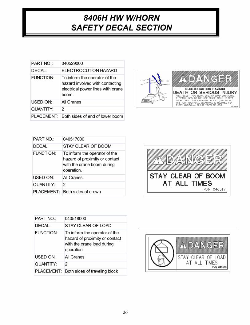
PART NO.: 040529000
DECAL: ELECTROCUTION HAZARD
FUNCTION: To inform the operator of the
hazard involved with contacting
electrical power lines with crane
boom.
USED ON: All Cranes
QUANTITY: 2
PLACEMENT: Both sides of end of lower boom
PART NO.: 040517000
DECAL: STAY CLEAR OF BOOM
FUNCTION: To inform the operator of the
hazard of proximity or contact
with the crane boom during
operation.
USED ON: All Cranes
QUANTITY: 2
PLACEMENT: Both sides of crown
PART NO.: 040518000
DECAL: STAY CLEAR OF LOAD
FUNCTION: To inform the operator of the
hazard of proximity or contact
with the crane load during
operation.
USED ON: All Cranes
QUANTITY: 2
PLACEMENT: Both sides of traveling block
8406H HW W/HORN
SAFETY DECAL SECTION

27
8406H HW W/HORN
SAFETY DECAL SECTION

28
4-5.0
8406H HW W/HORN
DECAL LAYOUT P/N: 480988021

29
DECAL LAYOUT P/N: 480988021
ITEM NO. QTY PART NO. DESCRIPTION
1 2 040517000 DECAL STAY CLEAR OF BOOM
2 2 040519000 DECAL DANGER SCISSOR POINT
3 2 040529000DECAL DANGER "ELECTROCUTION HAZARD"
POWER LINE
4 1 040579000 DECAL OPERATION INSTRUCTIONS
5 1 040580000 DECAL TRAINED OPERATOR
6 1 040587000 DECAL WARNING LOAD SENSOR
7 2 040624000 DECAL AUTO CRANE
8 1 040632000 DECAL WARNING - OVERLOAD
9 1 320318000 DECAL ANGLE INDICATOR CS
10 1 320318001 DECAL ANGLE INDICATOR SS
11 1 330622000 DECAL SERIAL NO
12 2 360034000 DECAL AUTO CRANE LOGO
13 1 480851000 DECAL 8406H
14 1 460169000 DECAL WARNING, REMOTE CONTROL
15 2 480988022 DECAL, LOAD CHART 8406H
16 2 040518000 DECAL STAY CLEAR OF LOAD
17 2 480853000 DECAL MAX BLOCK LOAD
18 1 040824000 DECAL, AMERICAN FLAG, MADE IN THE U.S.A.``
8406H HW W/HORN

30
5-1.0
8/8/08
NOTE: C.G. IS APPROXIMATE
8406H HW W/HORN
GENERAL DIMENSIONS

31
8406H HW W/HORNMOUNTING AND INSTALLATION
1. Check to make sure the following items are with your crane. Please note the different, model specific, quantities.
2. Pressure and return hoses are not furnished with this crane. The hoses must be provided by the installer and the lengths determined at installation.
REQUIREMENTS FOR INSTALLATION USING 23 GALLON RESERVOIR(*) A. RETURN LINE FROM CRANE TO RESERVOIR (IN COMPARTMENT): -10 SAE 100R2 (OR EQUIVALENT).
HOSE LENGTH IS DETERMINED BY INSTALLER. RETURN LINES LONGER THAN 6 FEET SHOULD BE SIZE –12. HOSE END FITTINGS ARE –10 JIC FEMALE SWIVEL (CRANE END) AND –10 JIC FEMALE SWIVEL (RESERVOIR END).
B. PRESSURE LINE FROM PUMP TO CRANE: -8 SAE 100R12 (OR EQUIVALENT) WITH A 2,850 PSI
MINIMUM WORKING PRESSURE. HOSE LENGTHS IS DETERMINED BY INSTALLER. HOSE END FITTINGS ARE BOTH –8 JIC FEMALE SWIVEL.
(*) NOTE: 23 GAL RESERVOIR IS MINIMUM REQUIREMENT FOR CRANE ONLY. THE ADDITION OF OTHER AUXILLARY EQUIPMENT WILL REQUIRE ADDITIONAL CAPACITY.
CAUTION – FAILURE TO USE CLEAN HYDRAULIC HOSES AND COMPONENTS
MAY CONTAMINATE THE CRANE AND HYDRAULIC SYSTEM AND VOID
WARRANTY.
3. Crane must be provided with a flow of 13 gallons per minute and a pressure of 2,750 PSI. Excess flow will cause erratic operation, and too little flow will cause poor crane operation.
4. Vehicle should meet minimum GVW rating of 20,500 pounds.
5. The vehicle MUST be equipped with an engine speed control and tachometer.
6. Make sure mounting surface is properly reinforced to withstand 50,000 ft-lb capacity loading of crane and that outriggers are used to provide total stability for the truck.
7. A 13 1/2” diameter hole should be cut out of mounting location (centered with mounting bolts) for access to hydraulic connections.
8. Make sure the mounting bolts are 7/8” dia, grade 8-UNF. Torque bolts to 501 ft-lbs.
ITEM NO. QTY. PART NO. DESCRIPTION
1 4 015100000 7/8-14 X 4 HH GR 8
2 4 022200000 WASHER SP LK 7/8 CP
3 4 018900000 NUT HX 7/8 NFCP GR8
4 1 480689000 FUSE 15 AMP TIME-DELAY
5 1 480688000 FUSE HOLDER IN-LINE WATERPROOF
6 120 800596000 WIRE 16G 600V 1C YEL
7 6 634401000 WIRE TIE 7 INCHES LONG
8 6 750738000 WIRE TIE STICK ON RETAINER
9 5 320357000 CONNECTOR FEM SPD
10 1 320363000 PLUG RELAY
11 1 340638000 CONDUCTOR POWER
12 1 320355000 POWER RELAY
13 1 480988011 MANUAL, 8406H, HW, W/ HORN
14 1 480988022 DECAL, LOAD CHART, 8406H
15* 1 680040001 PENDANT ASSY, 8 FUNC.,
16* 1 366520003 JUNCTION BOX ASS'Y W/ UNLOAD
17* 1 366466000 WIRE HARNESS, TRUCK FUNCTIONS
* ITEMS ARE IN ELECTRICAL KIT
IN.

32
9. When crane is not in operation, a boom support should always be used. Traveling block should be connected to hook loop.
10. Electrical hookup:
Wiring (FM – cable from base of crane, HW – cable from junction box):A. CONNECT THE BLACK WIRE TO THE BATTERY NEGATIVE (GROUND).
B. CONNECT THE RED WIRE TO FUSED 12VDC POWER. 12VDC POWER SHOULD BE SUPPLIED THROUGH A DEDICATED SWITCH THAT IS POWERED ONLY WHEN THE IGNITION SWITCH IS ON.
C. OPTIONALLY, USE THE WHITE WIRE FOR ENGINE FAST/SLOW (12VDC MAINTAINED-FM ONLY).
D. OPTIONALLY, USE THE BLUE WIRE FOR ENGINE START.
E. OPTIONALLY, USE THE ORANGE WIRE FOR ENGINE STOP. F. OPTIONALLY, USE THE GREEN WIRE FOR AUXILIARY (12VDC MAINTAINED-FM ONLY).
NOTE: ALL ELECTRICAL CONNECTIONS BETWEEN THE CRANE AND THE VEHICLE SHOULD BE MADE USING RELAYS TO ISOLATE THE ELECTRICAL SYSTEMS OF EACH AS MUCH AS POSSIBLE.
WARNING! FAILURE TO CORRECTLY PLUMB AND WIRE CRANE CAN CAUSE INADVERTENT
OPERATION AND DAMAGE TO CRANE AND/OR PERSONNEL!
11. Once crane and plumbing are installed on the truck, fill the reservoir to top of sight glass (mobile DTE 13 or equal). Before operating crane, connect together the pressure and return hoses going to base of crane using 10-12 JIC union and engage PTO with engine running. Allow oil to circulate for 15 to 20 minutes. This will flush contaminants from the system back to the return line filter. Operate all cylinders to full extension and retraction a minimum of six times, to bleed air from system. Return all cylinders to the stored position and disengage PTO. Refill reservoir to top sight glass. To ensure 13 gallons per minute (GPM), install an in-line flow meter between the crane and the reservoir in the return hose.
12. Load test the crane to ensure proper functioning and truck stability. 13. Make certain the owner’s manual is delivered to the customer. 14. For additional help: call the service department at the Auto Crane Company (918) 836-0463 (Tulsa,
Oklahoma).
WARNING
FEDERAL LAW (49 CFR PART 571) REQUIRES THAT THE FINAL STAGE MANUFACTURER OF A
VEHICLE CERTIFY THAT HE VEHICLE COMPLIES WITH ALL APPLICABLE FEDERAL REGULATIONS. ANY MODIFICATIONS PERFORMED ON THE VEHICLE PRIOR TO THE FINAL STAGE ARE ALSO CONSIDERED INTERMEDIATE STAGE MANUFACTURING AND MUST BE CERTIFIED AS TO COMPLIANCE. THE INSTALLER OF THIS CRANE AND BODY IS CONSIDERED ONE OF THE MANUFACTURERS OF THE VEHICLE. AS SUCH A MANUFACTURER, THE INSTALLER IS RESPONSIBLE FOR COMPLIANCE WITH ALL APPLICABLE FEDERAL AND STATE REGULATIONS, AND IS REQUIRED TO CERTIFY THAT THE VEHICLE IS IN COMPLIANCE.
IT IS THE FURTHER RESPONSIBILITY OF THE INSTALLER OF THE CRANE TO
COMPLY WITH THE OSHA TRUCK CRANE STABILITY REQUIREMENTS AS SPECIFIED BY 29 CFR PART 1910.180 (C) (1).
8406H HW W/HORNMOUNTING AND INSTALLATION

NOTES

34
GENERAL ASSEMBLY P/N: 4809880028406H HW W/HORN

35
ITEM NO. PART NO. QTY. DESCRIPTION
1 480988202 1 PEDESTAL ASS'Y 8406, HW, W/ HORN
2 480988100 1 BOOM ASSEMBLY, 8406H
3 480988020 1 PIN, PIVOT, 8406H
4 021600000 1 WASHER FL 1/2
5 738642000 1 SCREW HX HD 1/2-13UNC X 1 3/4 LG GR8
6 021500000 1 WASHER, SP LK 1/2
7 017701000 1 NUT HX 1/2-13UNC
8 360676000 1 PIN, CYLINDER
9 239300000 1 ZERK, GREASE
10 320976000 1 WASHER, FLAT, 3/8 SAE HARDENED
11 021100000 1 WASHER SP LK 3/8
12 366159000 1 SCREW HX HD 3/8-16UNC X 1 1/2 LG GR8
13 360678000 1 PIN, 3/16 COTTERLESS RING
14 367238000 1 CAP, 10 JIC
15 360445000 1 CAP, 8 JIC
16 360677000 1 PIN, 1/4 COTTERLESS RING
17 480841000 1 WIRE ROPE ASSEMBLY 3/8 HEAVY DUTY
18 480854000 1 TRAVELING BLOCK ASSEMBLY
19 360124000 1 PIN HITCH
20 470076000 1 PIN, 1 DIA 4-11/16 LG
21 480988026 1 SHIP KIT, 8406H, HW, W/ HORN
22 480988025 1 VALVE COVER
23 480988021 1 DECAL LAYOUT/KIT 8406H
24 330622000 1 DECAL SERIAL NO
25 366719115 1 DISC, HORN, ELECTRIC. VOLTAGE 12
8406H HW W/HORN
GENERAL ASSEMBLY - P/N: 480988002

36
8406H HW W/HORN
PEDESTAL ASSEMBLY P/N: 480988202
4042
41 33
39
35
3840
3436
32
37
49
49 HD
HU
59
6466
5
7
10
5
28
31
47
47
62
18
13
1615
1412
28
31
72
71
20
1621
22
TORQUE TO 200 FT-LBSDRY (NO THREAD LUBE)
TORQUE TO 200 FT-LBSDRY (NO THREAD LUBE)
11
51
6150
63
EXT
RET
56
57
HD
HU
T
P
53
53
54
54
55
55
BD
BU
52
52
RET
EXT
56
57
CW
CCW HD
HU
T
P
VALVE BANK HOSING DETAIL
HYDRAULICS:
“HD” PORT: HOIST DOWN
“HU” PORT: HOIST UP
“CW” PORT: ROTATION CW
“CCW” PORT: ROTATION CCW
“BU” PORT: LIFT CYL EXTEND
“BD” PORT: LIFT CYL RETRACT
“EXT” PORT: EXT CYL EXTEND
“RET” PORT: EXT CYL RETRACT
CYLINDER SEAL KIT: 480988251 (CTD)
COUNTER BALANCE CARTRIDGE: 480188100

37
PEDESTAL ASSEMBLY P/N: 4809882028406H HW W/HORN
A
VALVE480188100
12
5
10
6
5
1
3
67
70
71
19
23
2529
28
24
60
28
43
59
4
2
ADD 6 INCWHERE IT RUBS AGAINST THE
ADD 6 INCWHERE IT RUBS AGAINST THE VAL
30
TORQUE TO 200 FT-LBSDRY (NO THREAD LUBE)
77
78
ADD 6 INCHES OF NYLON HOSE SLEEVE TO 812303023
WHERE IT RUBS AGAINST THE SIDE PLATE
ADD 6 INCHES OF NYLON HOSE SLEEVE TO 812303023
WHERE IT RUBS AGAINST THE VALVE BLOCK

38
7-6.0 1/12/10
PEDESTAL ASSEMBLY P/N: 480988202
ITEM NO.
QTYPART
NUMBERDESCRIPTION
1 1 480988220 BASE PLATE WELDMENT
2 1 480988210 PEDESTAL WELD, LARGE CRANE
3 1 480023002 BEARING ROTATION 5005-8005
4 4 006205000 SCREW SOC HD 5/8-11UNC X 1 1/4 LG
5 36 023902000 WASHER FL 5/8 HARDENED
6 24 012198000 SCREW HX HD 5/8-11UNC X 1 3/4 LG GR8
7 2 366393000 SCREW HX HD 5/8-11UNC X 2 1/2 LG GR8
8 4 011608000 SCREW HX HD 1/2UNC X 2 GR5
9 1 006200000 SCREW HX HD 1/4UNC X 1 1/4 GR5
10 10 490171000 SCREW HX HD 5/8-11UNC X 2 1/4 LG GR8
11 1 366333000 BEARING, SPHERICAL 1.25 ID
12 1 480988250 CYLINDER, LIFT, 8406H, STROKE - 27.81
13 1 360676000 PIN, CYLINDER
14 1 366159000 SCREW HX HD 3/8-16UNC X 1 1/2 LG GR8
15 5 021100000 WASHER SP LK 3/8
16 2 320976000 WASHER, FLAT, 3/8 SAE HARDENED
17 1 239300000 ZERK, GREASE
18 1 360678000 PIN, 3/16 COTTERLESS RING
19 1 360162000 RING, ECCENTRIC
20 1 360207000 RETAINER ECCENTRIC RING
21 1 020601000 WASHER SP LK 5/16
22 1 007807000 SCREW HX HD 5/16-18UNC X 3/4 LG GR5
23 1 480011000 SEAL ROTATION BOX
24 1 160407 GEAR BOX, ROTATION
25 1 366440000 ROTATION MOTOR
26 2 021502000 WASHER SP LK 1/2 HI COLLAR
27 2 012197000 SCREW SOC HD 1/2-13UNC X 1/2 LG
28 14 021500000 WASHER, SP LK 1/2
29 2 009118000 SCREW SOC HD 1/2-13UNC X 2 LG
30 2 011202000 SCREW HX HD 1/2-20UNF X 2 3/4 LG GR5
31 2 017704000 NUT HX HVY 1/2-20UNF
32 1 480988255 BRACKET, ROT STOP
33 1 366676000 COVER, ROTATION STOP
34 1 460110100 ROTATION STOP SWITCH ASSEMBLY, 24"
35 4 006210000 CAPSCREW-#8-32 X 7/8 LG SOC HD Z/P
36 4 019700000 WASHER SP LK #8
37 4 725321000 NUT HX NYLK #8-32UNC
38 1 366675000 WASHER, NYLON
8406H HW W/HORN

39
PEDESTAL ASSEMBLY P/N: 480988202
ITEM NO.
QTYPART
NUMBERDESCRIPTION
39 1 366673000 PIN, ROTATION STOP
40 2 017301 NUT HX NYLK 3/8-16UNC CP
41 1 366671000 ARM, ROTATION STOP
42 1 460079000 BEARING, ROTATION STOP
43 14 320588000 WASHER, FL 1/2, HARDENED
44 4 017701000 NUT HX 1/2-13UNC
45 2 460177250 PLATE, MANIFOLD MOUNT, LARGE CRANE
46 1 813008000 KIT, HOSE, 8406H
47* 2 200876000 FITTING 6 SAE/6 JIC STRAIGHT
48* 2 490198000 FITTING 10SAE(M)/6JIC ELBOW 90
49* 2 372041000 FITTING 8JIC/10SAE STRAIGHT 8-10 F5OX
50* 1 490199000 FITTING STR 10-SAE/10-JIC
51* 1 367145000 FITTING STR 8-SAE/8-JIC
52* 2 812303023 HOSE ASSY 8 JIC STR
53* 2 812203022 HOSE ASSY, -6 JIC FEM, STR
54* 2 812203037 HOSE ASSY 6 JIC STR
55* 2 480205000 HOSE ASSY 6 STR X 19.25
56* 1 812309026 HOSE ASSY 8 STR/90
57* 1 812409023 HOSE ASSY 10 STR/90
58* 41" 374086000 NYLON HOSE SLEEVE, 1.81" ID, 5" LONG
59 1 123315 WINCH- RPH 4200
60 6 011609000 SCREW 1/2 X 2 1/2NC GR5
61 1 366698000 CORD GRIP .375-.500 3/4" HUB
62 1 480988252 LOAD SENSOR SWITCH, 2620 PSI
63 1 750426000 PLUG, 1/4 NPT, SOC HD
64 1 320355000 RELAY, BOSCH
65 1 460177253 WASHER, 0.28 ID X 1.0 OD X .06 THICK
66 1 016300000 NUT HX NYLK 1/4-20UNC
67 1 366522001 HOUSING, PLUG, DEUTSCH 12-PIN
68** 1 470011000 CABLE ASSY, AMP TO 2-PIN DEUTSCH
69 1 470010000 AMPLIFIER ASSY, 4-PIN DEUTSCH
70 1 366522002 WEDGE, DEUTSCH PLUG, 12 SOCKET
71 1 366358000 FITTING, -10 SAE / -10 JIC, SWIVEL, STR
72 1 366359000 FITTING, -8 SAE / -8 JIC, SWIVEL, STR
73 1 460140000VALVE, CONTROL 4 FUNC,W/BOOM DOWN RELIEF
74 4 330371000 SCREW HX HD 3/8-16UNC X 1 LG GR8
75 1 470091001KIT, ELECTRICAL,LARGE H CRANE, HW, W/ HORN
76 1 680195002 HARNESS, HW, W/ HORN, LARGE CRANE
77 1 366367001 HOUSING, DEUTSCH 2-PIN PLUG
78 1 366367002 WEDGE, DEUTSCH PLUG, 2 PIN
* NOTE: ITEMS IN HOSE KIT
**NOTE: ITEMS IN ELECTRICAL KIT
8406H HW W/HORN

40
BOOM ASSEMBLY P/N: 4809881018406H HW W/HORN
2122
32
WIRING (REVERSIBLE)BLACK TO N.O. WHITE TO COMMON
10
12
28
26
16 14
1
15
4
31
53
20
19
17
27
24
32
30
18
6
29
78
9
13
11
6
2
29
16
14
33
357
7
15
11
777
9
77
7
31
SHIM TO FIT
VALVE480188000
34
(ORIENT ARROWTOWARDS CROWN) 36
CONNECT TORETRACT CYL. TUBE
NOTES:
1 APPLY LOCTITE 609 TO THREADS BEFORE INSTALLING.
2 APPLY ANTI-SEEZE TO INSIDE AND OUTSIDE OF BUSHING
SHIM TO FIT
1
1
4 PLACES
2 PLACES
19
23 25
2325CYL SEAL KIT P/N: 480988151
C’BAL P/N: 36053001
41
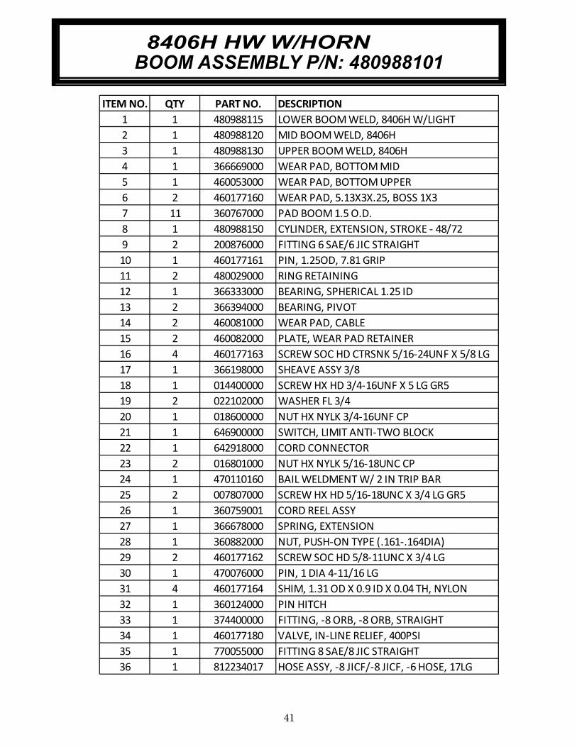
ITEM NO. QTY PART NO. DESCRIPTION
1 1 480988115 LOWER BOOM WELD, 8406H W/LIGHT
2 1 480988120 MID BOOM WELD, 8406H
3 1 480988130 UPPER BOOM WELD, 8406H
4 1 366669000 WEAR PAD, BOTTOM MID
5 1 460053000 WEAR PAD, BOTTOM UPPER
6 2 460177160 WEAR PAD, 5.13X3X.25, BOSS 1X3
7 11 360767000 PAD BOOM 1.5 O.D.
8 1 480988150 CYLINDER, EXTENSION, STROKE - 48/72
9 2 200876000 FITTING 6 SAE/6 JIC STRAIGHT
10 1 460177161 PIN, 1.25OD, 7.81 GRIP
11 2 480029000 RING RETAINING
12 1 366333000 BEARING, SPHERICAL 1.25 ID
13 2 366394000 BEARING, PIVOT
14 2 460081000 WEAR PAD, CABLE
15 2 460082000 PLATE, WEAR PAD RETAINER
16 4 460177163 SCREW SOC HD CTRSNK 5/16-24UNF X 5/8 LG
17 1 366198000 SHEAVE ASSY 3/8
18 1 014400000 SCREW HX HD 3/4-16UNF X 5 LG GR5
19 2 022102000 WASHER FL 3/4
20 1 018600000 NUT HX NYLK 3/4-16UNF CP
21 1 646900000 SWITCH, LIMIT ANTI-TWO BLOCK
22 1 642918000 CORD CONNECTOR
23 2 016801000 NUT HX NYLK 5/16-18UNC CP
24 1 470110160 BAIL WELDMENT W/ 2 IN TRIP BAR
25 2 007807000 SCREW HX HD 5/16-18UNC X 3/4 LG GR5
26 1 360759001 CORD REEL ASSY
27 1 366678000 SPRING, EXTENSION
28 1 360882000 NUT, PUSH-ON TYPE (.161-.164DIA)
29 2 460177162 SCREW SOC HD 5/8-11UNC X 3/4 LG
30 1 470076000 PIN, 1 DIA 4-11/16 LG
31 4 460177164 SHIM, 1.31 OD X 0.9 ID X 0.04 TH, NYLON
32 1 360124000 PIN HITCH
33 1 374400000 FITTING, -8 ORB, -8 ORB, STRAIGHT
34 1 460177180 VALVE, IN-LINE RELIEF, 400PSI
35 1 770055000 FITTING 8 SAE/8 JIC STRAIGHT
36 1 812234017 HOSE ASSY, -8 JICF/-8 JICF, -6 HOSE, 17LG
BOOM ASSEMBLY P/N: 4809881018406H HW W/HORN

42
GEAR BOX P/N: 1604078406H HW W/HORN

43
GEAR BOX P/N: 160407
8406H HW W/HORN

44
6-11.0 8/8/08
52
34 20
20
25
31
27
28
49
15
25
33
472
8
16
6
48
39
30
43
47
29
46
2
45
17
8
42
517
4
42
38
17
40
35
37
7
12
36
13
1
19
14
11
32
44
185
21
50
41
26
23
2422
31
0
9
HOIST ASSEMBLY P/N: 1233158406H HW W/HORN

45
6-12.0 8/8/08
ITEM NO. QTY. PART NO. DESCRIPTION
1 1 234189 DRUM ASSEMBLY
2 1 306042 PISTON-BRAKE
3 1 315004 ANCHOR- CABLE
4 1 338300 END BRG-MOTOR END
5 1 338301 END BRG-GEAR HSG.
6 1 338302 HSG-BRAKE
7 4 346045 PIN-BRAKE
8 1 357513 SHAFT- INPUT
9 2 362291 SPACER - FOOT MOUNTING
10 4 362284 SPACER - TIE PLATE
11 1 402120 BEARING
12 1 402121 BEARING
13 1 412084 BUSHING-DRUM,MOTOR END
14 1 412085 BUSHING-DRUM,GEAR END
15 4 414129 CAPSCREW 5/16-18NCX3 LG HX HD GR-5
16 6 414303 BOLT-3/8-16NC X2 1/2,HXHD,GR-5, Z/P
17 8 414548 CAPSCREW-1/2-13NCX1 1/2,HXHD,Z/P,G5
18 2 414854 SCREW-1/4-20NCX1/2LG,RDHD,SLOT,Z/PL
19 1 414926 SETSCREW-3/8-16NC X1,SOCKET,NYLON
20 2 414948 CAPSCREW-1/2-13NCX1 1/4LG,SOCKET HD
21 1 416016 SETSCREW1/4-20NCX1/4 HX SOCK HD CUP
22 1 416080 SETSCREW-5/8-18NF X1 LG,HXSOCHD,CUP
23 1 418036 NUT-3/8-16 NC,HEX JAM,Z/P
24 1 418088 NUT-JAM 5/8-18NF HEX HD,ZINC PLT
25 2 418218 LOCKWASHER-1/2 ID MED SECT,ZINC PLT
26 1 426048 PLUNGER-CLUTCH,BLOCKED
27 1 431015 COUPLING-MOTOR
28 2 432018 FITTING
29 4 438022 DISC-BRAKE
30 1 442220 GASKET-BRAKE HSG.
31 1 442223 GASKET-MOTOR FLANGE
32 1 444085 GEAR-RING,P/M
33 1 456038 FITTING-VENT,BREATHER
34 1 458121 MOTOR-HYDRAULIC (RPH-3600)
35 1 462046 O-RING
36 1 462056 O-RING
37 1 462057 O-RING
38 1 462058 O-RING
39 1 462059 O-RING-BACK-UP
40 1 462060 O-RING-BACK-UP
GEAR BOX P/N: 1233158406H HW W/HORN

46
6-13.0 8/8/08
ITEM NO. QTY. PART NO. DESCRIPTION
41 1 472052 PLUG
42 2 474065 TIE PLATE
43 5 474111 PLATE-SEPARATOR, BRAKE
44 1 486080 SEAL
45 1 490037 SNAP RING
46 6 494110 SPRING-BRAKE
47 4 494112 SPRING
48 1 509009 TUBE ASSY
49 1 516033 VALVE-MOTOR CONTROL
50 1 518037 THRUST WASHER
51 1 518047 THRUST WASHER
52 1 518052 THRUST WASHER
8406H HW W/HORN
P/N: 123315

47
ITEM NO.
QTY
PART NUMBER
DESCRIPTION
1 1 480860000 TACKLE LOWER
2 2 480859000 SIDE PLATE TRAVELING BLOCK
3 1 480366000 HOOK SWIVEL 6 METRIC TON
4 1 480861000 SHEAVE ASSY 3/8 ROPE
5 1 490313000 BOLT, SHEAVE W/ZERK FITTING
6 1 018600000 NUT HX NYLK 3/4-16UNF CP
7 2 360605000 PIN, BLOCK
8 2 366813000 PIN HITCH
9 1 480368000 PIN SWIVEL HOOK
10 1 360124000 PIN HITCH
11 2 480853000 DECAL MAX BLOCK LOAD
12 2 040518000 DECAL STAY CLEAR OF LOAD
8406H HW W/HORN
TRAVELING BLOCK ASSEMBLY P/N: 480854000

48
8406H HW W/HORN
ELECTRICAL SCHEMATIC P/N: 680195003
RE
D/W
HIT
E
GR
N/W
HT
HO
RN
VA
LV
EC
TR
LP
RP2
1
BL
K
WH
T
2 (
NO
T U
SE
D)
1
BA
SE
OF
CR
AN
E
1 2 3 4
WH
ITE
/RE
D
WH
TB
LK
2 2W
HT
/RE
D
1 1
BL
K
RE
D
A2
B
22
11
B DC E F GA J LK M N P S UT
OR
G/R
ED
VB
LU
/RE
D
R
BL
K/W
HT
H
PENDANT SCHEMATIC
FOR
REFRENCE 680040001
19 PIN CONNECTOR
1 2 4 5 63 7 8 9 12
11
10
HO
IST
DO
WN
HO
IST
UP
RO
TA
TE
CC
W
BO
OM
UP
RO
TA
TE
CW
GR
EE
N
RE
D/B
LA
CK
WH
ITE
/BL
AC
K
OR
AN
GE
WH
ITE
RO
T S
W C
CW
RO
T S
W C
W
GR
N21 3 4
3 421
BL
K
BL
KR
ED
RE
D
WH
T
BL
AC
K
1
BO
OM
DO
WN
EX
TE
ND
RE
TR
AC
T
PO
WE
R
VA
LV
E
UN
LO
AD
ING
MODIFIER
AMP
RE
D
2 3 4 6 7 (
NO
T U
SE
D)
5 8 (
NO
T U
SE
D)
GR
OU
ND
AU
XIL
IAR
Y
EN
GIN
E S
TO
P
EN
GIN
E S
TA
RT
EN
GIN
E F
AS
T/S
LO
W
BL
AC
K
WH
ITE
GR
EE
N
BL
UE
OR
AN
GE
87
30RE
LA
Y
BO
SC
H
PR
ES
S S
W1
RE
D/W
HT
BLK
RE
D/W
HIT
E
RELAY
BOSCH
86
85
RE
D/W
HIT
E
WHT/RED
OR
AN
GE
/BL
AC
K
BL
UE
GR
EE
N/B
LA
CK
BL
K
BL
K/W
HT
BL
U/B
LK
RE
D/W
HIT
E
GR
N
BL
K
RE
D
RE
D
GR
EE
N
OR
AN
GE
BL
AC
K
RE
D/B
LA
CK
BL
UE
OR
AN
GE
/BL
AC
K
GR
EE
N/B
LA
CK
WH
T/R
ED
BL
U/B
LK
BLK/WHT
WH
ITE
RED/WHITE
GR
N/W
HT
BL
U/W
HT
BL
K/R
ED
BLACK/WHITE
JUN
CT
ION
BO
X
WH
T/B
LK
12
PIN
CO
NN
EC
TO
R

49
8406H HW W/HORN
MAIN WIRING HARNESS P/N: 680195002
65
.0"
5.5
"
9.0
"
4.0
"
65
.0"
48
.0"
A2
B S
WIT
CH
PR
ES
S S
WIT
CH
-1
RO
TA
TE
SW
ITC
H
56
3
24
1
BA
30
8
WHT/RED 21.0"
8
BL
K
UL
V
10
13
GR
N
RE
D/B
LK
WH
T/B
LK
OR
G
BL
U
GR
N/B
LK
OR
G/B
LK
RE
D
WH
T/B
LK
RE
D/B
LK
GR
N
RE
D
OR
G
WH
T
BL
U
GR
N/B
LK
OR
G/B
LK
BL
K
PIN
-12
PIN
-1
PIN
-2
PIN
-3
PIN
-4
PIN
-5
PIN
-6
PIN
-7
PIN
-8
PIN
-9
BL
U/B
LK
BL
K/W
HT
PIN
-10
PIN
-11
BL
K/W
HT
BL
U/B
LK
PIN
-1
PIN
-2
11
12
2
BL
K
HU
HD
CC
W
CW
BU
BD
EX
T
RE
T
AM
P
49
12
7
4
PIN
-4
PIN
-3
PIN
-2
PIN
-1
PIN
-2
PIN
-1
PIN
-1
PIN
-2
PIN
-3
PIN
-4
GR
N
WH
T
RED/WHT 21.0"
11
BLK 21.0"
BL
K 1
5.0
"
BL
K 1
5.0
"
RE
D/W
HT
20
.0"
WH
T/R
ED
20
.0"
6.0
"
85
87
86
87
A
BL
K/W
HT
GR
N
WH
T/R
ED
WH
T
RE
D/W
HT
BL
K
WH
T
RE
D/W
HT
WH
T/R
ED
WH
T/R
ED
RE
D/W
HT
RE
D/W
HT
HE
AT
SH
RIN
K
4
GR
N/W
HT
PIN
-1
4
HO
RN
+
SP
LIT
LO
OM
(T
RIM
IF
NE
CE
SS
AR
Y)
*S
HIP
LO
OS
E*
GR
N/W
HT

50
8406H HW W/HORN
MAIN HARNESS FUNCTION P/N: 680195002
FUNCTION PIN WIRE COLOR NOTES
1 GREEN TO PIN 1 (MAIN)
2 WHITE/RED TO A2B GROUND
1 RED/BLACK TO PIN 2 (MAIN)
2 RED/WHITE GROUND
1 WHITE/BLACK TO PIN 3 (MAIN)
2 BLACK TO PIN 1 (ROTATE SWITCH)
1 ORANGE TO PIN 4 (MAIN)
2 WHITE TO PIN 4 (ROTATE SWITCH)
1 WHITE TO PIN 5 (MAIN)
2 RED/WHITE GROUND
1 BLUE TO PIN 6 (MAIN)
2 WHITE/RED TO A2B GROUND
1 GREEN/BLACK TO PIN 7 (MAIN)
2 WHITE/RED TO A2B GROUND
1 ORANGE/BLACK TO PIN 8 (MAIN)
2 RED/WHITE GROUND
1 RED/WHITE TO PIN 2 (PRESS SWITCH-1)
2 WHITE/RED TO PIN 86 (RELAY)
1 BLACK GROUND
2 RED/WHITE TO PIN 1 (A2B SWITCH)
1 BLACK TO PIN 2 (CCW)
2,3 GREEN GROUND
4 WHITE TO PIN 2 (CW)
1 BLUE/BLACK TO PIN 11(MAIN)
2 BLACK/WHITE TO PIN 10 (MAIN)
3 BLACK/WHITE TO PIN 10 (MAIN)
4 BLACK TO PIN 9 (MAIN)
1 RED TO PIN 12 (MAIN)
2 RED/WHITE GROUND
BOSCH
RELAY 86 WHITE/RED PIN 2, (FOR A2B SW)
BOSCH
RELAY 85 BLACK TO PIN 9 (MAIN)
BOSCH
RELAY 87 WHITE/RED PIN 2, (FOR PRESS SW-1)
BOSCH
RELAY 30 RED/WHITE PIN 1, (FOR PRESS SW-1)
HORN (+) 1 GREEN/WHITE PIN 1, (FOR HORN POWER)
BOOM DN
HOIST UP
HOIST DN
ROTATE CCW
ROTATE CW
BOOM UP
UNLOADING
VALVE
EXTEND
RETRACT
AMP
A2B SWITCH
PRESSURE
SWITCH
ROTATE
SWITCH
3 COND
CABLE

51
8406H HW W/HORN
JUNCTION BOX ASSEMBLY P/N: 366520003
A A
1313 1211
16
1SECTION A-A
SCALE 1 : 3
6
2
1
3
5
10 8
7
GND
14
INDIVIDUAL HEAT SHRINK TUBING
ON BACK SIDE OF CANNON PLUG
HEAT SHRINK AND SEAL WIRE BUNDLE
ONCE ALL CONNECTIONS ARE MADE
15
19 PIN 8 PIN 12 PIN 2 PIN GND WIRE COLOR WIRE LENGTH
A 5 RED 6.5
B 1 GREEN 6.5
C 4 ORANGE 6.5
D 3 RED/WHITE 4
E 3 BLACK 6.5
F 2 RED/BLACK 6.5
G 6 BLUE 6.5
H 8 ORANGE/BLACK 6.5
J 7 GREEN/BLACK 6.5
K - 12 WHITE/BLACK 6.5
L 1 WHITE 4
M 11 BLUE/BLACK 6.5
N GND BLACK/WHITE 5.5
P 1 GREEN/WHITE 9
R 5 BLUE/WHITE 4
S 6 BLACK/RED 4
T 9 WHITE/RED 6.5
U - - NOT USED N/A
V - - NOT USED N/A
10 GND BLACK/WHITE 3
2 GND BLACK/WHITE 5
12 RED 5.0

52
ITEM NO. QTY PART NO. DESCRIPTION
1 1 366470000 JUNCTION BOX
2 1 366095000 PLUG, 19 PIN
3 1 366523001 HOUSING, DEUTSCH 8-PIN RECEPTACLE
4 1 366471000 COVER, JUNCTION BOX
5 1 366524001 HOUSING, DEUTSCH 12-PIN RECEPTACLE
6 1 366097000 CAP W/CHAIN (FOR RECEPTACLE)
7 4 366517000 RIVET NUT, 6-32
8 13 019600000 WASHER SP LK # 6 CP
9 16 001004000 SCREW PN HD #6 X 3/4 LG
10 13 015400000 NUT HX #6-32UNC
11 1 366524002 WEDGE, DEUTSCH RECEPTACLE, 12 PIN
12 1 366523002 WEDGE, DEUTSCH RECEPTACLE, 8 PIN
13 19 366376003 CONTACT, DEUTSCH
14 1 000101000 TERMINAL RING, 5/32, 14-16 GA
15 1 360769001 HOUSING, DEUTSCH 2-PIN RECEPTACLE
16 1 360769002 WEDGE, DEUTCH 2-PIN RECEPTACLE
17 1 366469002 DECAL, JUNCTION BOX
8406H HW W/HORN
JUNCTION BOX ASSEMBLY P/N: 366520003

53
8406H HW W/HORN
PENDANT ASSEMBLY P/N: 680040001
18
17
GAKLTFBCSREJHPDMN
19
RED
BLUE
GREEN
WHITE
BLACK
ORANGE
BLUE W/ WHITE
BLACK W/ RED
RED W/ BLACK
WHITE W/ RED
WHITE W/ BLACK
1517
GREEN W/ WHITE
RED W/ WHITE
BLACK W/ WHITE
BLUE W/ BLACK
ORANGE W/ BLACK
GREEN W/ BLACK
17
UP
BOOM
WHITE (POWER)
OFFON
17
2413ENGINE
START STOP
POWER
1414UP
CCW ROTATE
CW
ON
HORN
EXTEND14
IN
IDLE
SLOW
19
DOWN
18
24
1924
14
19
HOIST18
OUT
20FAST
7
AS VIEWED FROMBACKSIDE OF
23 PENDANT.
BLUE
YELLOW
WHITE
DOWN
62 13
POTENTIOMETER
ORANGE
7
5
4
6
10
21
22
12 7
1415
14
14
7
11
9
1
3
14
14
2
8
20

54
8406H HW W/HORN
PENDANT ASSEMBLY P/N: 680040001
ITEM NO. QTY PART NO. DESCRIPTION
1 1 480501000 PENDANT HOUSING
2 1 480518001 DECAL, PENDANT ASSY, 8 FUNC.
3 1 480504000 PENDANT BACK PLATE
4 1 600820000 CORD GRIP, 3/4 NPT, .50-.625" CORD
5 1 680113000 PENDANT CABLE BAYONET
6 1 480507000 POTENTIOMETER ASSY, W/ BRACKET
7 2 750090000 SWITCH, TOGGLE ON/OFF
8 4 001004000 SCREW PN HD #6 X 3/4 LG
9 2 002607000 SCREW RD HD #10-24UNC X 3/4 LG CP
10 2 015801000 NUT HX NYLK #10-24UNC ZP
11 1 480506000 TRIGGER, PENDANT
12 1 480517000 SCREW SOC HD #10UNF X 5/8 GR5
13 1 622000000 SWITCH, TOGGLE SPDT
14 4 634200000 SWITCH-2TL1-7
15 1 366719120 PUSH BUTTON SWITCH KIT
16 2 750737000 TIE WRAP PUSH-IN
17 1 480526000 COND.ASS'Y
18 3 622347000 CONDUCTOR ASSY
19 4 622346000 CONDUCTOR ASSY
20 4 636600000 JUMPER BAR
21 1 005003000 SCREW PN HD #8 X 3/8 CP GR3 SELF TAP
22 1 480523000 SPRING,TRIGGER RETURN
23 1 480524000 COND.ASSY (PROP)
24 3 660302000 COND 16G 14/10-14/6 WT 2

55
721
A
A
WHITE
INSTALL ON:
WHITE W/ RED T
6
ORANGE
RED
GREEN
INSTALL ON:
BLACK
RED W/BLACK T
RED W/WHITE T
GREEN W/BLACK T
GREEN W/WHITE T
BLUE W/WHITE T
BLACK W/ RED T
WHITE W/BLACK T
ORANGE W/BLACK T
BLUE
4
BLACK W/WHITE T
BLUE W/BLACK T
INSTALL ON:5
3
VIEW A-A
E GF
B N U
D
C
R S
VP T
MA L
WIRING GUIDE
N-BLACK W/WHITE T
P-GREEN W/WHITE T
R-BLUE W/WHITE T
S-BLACK W/RED T
T-WHITE W/RED T
U-ORANGE W/RED T
V-BLUE W/RED T
M-BLUE W/BLACK T
D-RED W/WHITE T
K-WHITE W/BLACK T
J-GREEN W/BLACK T
H-ORANGE W/BLACK T
F-RED W/BLACK T
G-BLUE
E-BLACK
C-ORANGE
A-RED
B-GREEN
K
H
J
L-WHITE
ITEM NO. QTY. PART NO. DESCRIPTION
1 1 366098000 PLUG, CONNECTOR
2 1 480515000 CLAMP, CABLE
3 30' 480594000 CABLE, CONDUCTOR (19 COND)
4 2 000101000 TERMINAL RING #6 / 14-16 GA
5 2 480510000 CONNECTOR, BULLET, FEMALE
6 13 002012000 TERMINAL RING #6 / 18-22 GA
7 6" 490243000 TUBING, HEAT SHRINK
8406H HW W/HORN
PENDANT CABLE ASSEMBLY P/N: 680113000

56
8-1.0
8406H HW W/HORN
HYDRAULIC SCHEMATIC P/N: 460140000

57
8406H HW W/HORN
HYDRAULIC CONTROL VALVE P/N: 460140000
8-2.0

58
ITEM QTY PART NO. DESCRIPTION
FR1 1 480839002 FLOW CONTROL
PV1 1 480839003 PROP VALVE
RV1 1 366365004 RELIEF VALVE
SV6 1 460160001 UNLOAD VALVE
SV3, SV4, SV5 3 320725001 CART VALVE
SV1, SV2 2 480839004 CART VALVE
CL1 1 366370001 COIL
CL2 7 460160002 COIL
CL3 2 480839005 COIL
FTG1 2 374017000 FITTING
FTG2 2 241175000 FITTING
FTG3 2 330645000 FITTING
FTG4 1 367145000 FITTING
FTG5 1 490199000 FITTING
FTG6 2 480195000 FITTING
FTG7 1 369127000 FITTING
FTG8 1 330348000 FITTING
ORF1 1 PLUG ORIFICE
ORF2 1 PLUG ORIFICE
PLG4 2 PORT PLUG
PLG6 11 PORT PLUG
NOT SHOWN 14 PLUG
BLK 1 BLOCK
8406H HW W/HORN
HYDRAULIC CONTROL VALVE P/N: 460140000

59
Counterbalance Valve Adjustment
1. With PTO disengaged and boom properly supported, remove the plug on the counterbalance valve. Install a pressure gauge (0-3000 PSI) into the port.
2. Engage PTO and insure pump flow is 8 to 9 GPM. With no load on boom, boom up to an angle of 70 degrees. Boom down and note pressure. If pressure reading is not approximately 1300 PSI, the counterbalance valve requires adjustment.
A. To increase the CB valve setting, loosen
nut and turn Allen head screw counter
clockwise.
B. To reduce the CB valve setting, loosen
nut and turn Allen head screw
clockwise.
3. Tighten nut on adjustment screw and repeat procedure if needed to obtain the proper pressure setting.
4. Disengage PTO, remove the pressure gauge and install plug. Crane is now ready for operation.
Notice:1. In an EMERGENCY situation when it becomes necessary to lower the boom without flow
present, the CB valve adjustment can be turned in until the boom begins to descend. Make sure the boom will lower onto a proper support. Loosen the lock nut and carefully turn adjustment screw clock-wise! Count the number of turns. Turn slowly until the boom just begins to lower, and remove hand/arm/fingers from cranes while boom is lowering.
2. Turning adjustment screw too far will cause valve to come apart on the inside. This condition is not repair-able
3. After boom is lowered, turn adjustment screw counter clockwise the approximate number of turns made dur-ing lowering procedure. After the problem is cor-rected, readjust the counterbalance valve using the procedure in this manual.
WARNING:DO NOT TRY TO ADJUST VALVES WHILE BOOM IS MOVING.Doing so may result in personal injury!
8406H HW W/HORN
COUNTERBALANCE VALVE ADJUSTMENT

60
8406H HW W/HORN
In the event that the electrical control system fails the crane can be operated using the manual overrides on the hydraulic control valve.
The overrides operate as follows: 1. Proportional – increase flow by turning clockwise. 2. Extend/Retract, Boom Up/Down, Rotate CW/CCW – push to operate boom down, pull to
operate boom up etc. See graphics above. 3. Hoist Up/Down, Unload Valve – Push in to operate.
Note: To manually activate a function the crane with no electrical power, you must first turn manual override on proportional clockwise then push in the unload valve while pushing or pulling the function you want to activate.
VALVE OVERRIDE OPERATION

61
8406H HW W/HORN LOAD CHART P/N: 480988022

P.O.Box 580697 • Tulsa, OK 74158697
4707 N.Mingo Rd.• Phone (918) 836-0463
LIMITED WARRANTY2 YEAR PARTS AND LABOR
Auto Crane will warranty to the consumer for a period of (2) years parts and labor from the date
of purchase. Each new Auto Crane unit they sell will be free under normal use and service from
defects in material and workmanship Date of purchase will be honored as the date indicated on
the Bill of Sale, which must accompany the Warranty Registration and be on file with Auto
Crane. Absent a valid Warranty Registration and appropriate documentation, the original date of
manufacture, as indicated by the serial number on the product, will be used to determine the
effective date of the 2 year warranty
The obligation of Auto Crane under this warranty is limited to the replacement or repair of parts
that appear to the manufacturer after review and/or inspection to be defective and paid flat rate
labor for replacing defective parts This warranty does not obligate Auto Crane to bear the travel
time charges in connection with the replacement or repair of defective parts Responsibility for
customer's claims arising, from misapplication, abuse, misuse or alteration of equipment or parts
lies with the distributor or user and no warranty obligation is assumed in these circumstances by
Auto Crane.
Auto Crane will in no event be liable for any consequential damages or contingent liabilitiesarising out of the failure of any Auto Crane Product or parts to operate properly
Auto Crane makes no warranty in respect to component accessories, it being subject tothe warranties of their respective manufacturers.
If field service, at the request of the distributor, is rendered and fault is found not to be with AutoCrane's product, the distributor shall pay the time and expense of the field representative.
Claims for service labor or other expenses that have incurred by the buyer without approval
or authorization or Auto Crane will not be accepted.
When applying for warranty, claims may be handled by contacting your nearest authorized
Auto Crane Distributor. All claims areto be filed in writing on an Auto Crane warranty Claim
Form.
AUTO CRANE COIVPANY IS UNDER NO OBLIGATION TOEXTEND THIS WARRANTY TO ANY CUSTOMER FOR WHICH AN AUTO CRANEDELIVERY REPORT FORMHAS NOT BEEN COMPLETED AND ON FILE WITH AUTO CRANE COMPANY

Auto Crane Company issues a limited warranty cer-
tifi cate with each unit sold. See warranty page.
Auto Crane will not assume responsibility or liability
for any modifi cations or changes made to unit, or
installation of component parts without authorization.
Note: This manual should remain with the crane at all times.