Embed Size (px)
Citation preview

8051Development
Board
Version 1.0(Manual Revised 8th July 2005)
1

Table of ContentsIntroduction...............................................................................................3
Why An 8051?..........................................................................................3Why An 8051 Development Board?................................................................3
Getting Started...........................................................................................6What You Should Have...............................................................................6Powering The Board..................................................................................6Basic Board Layout...................................................................................7Loading The Software................................................................................8
Installing The Compiler...........................................................................8Installing Example Code..........................................................................9
Compiling Your First Program......................................................................9Programming The Microcontroller...............................................................12
Installing The Programming Software........................................................12Using FLIP (Pre-check)..........................................................................13Using FLIP (Programming)......................................................................14
Program Listings........................................................................................16Demo1 Listing........................................................................................16Demo2 Listing........................................................................................17Demo3 Listing........................................................................................18Demo4 Listing........................................................................................19
Circuit Schematics.....................................................................................20Spares Parts.............................................................................................22
2

Introduction
Why An 8051?The first question I am normally asked is, “Why are you using a chip that's over 20years old?”. Luckily there are two good answers!
Firstly the 8051 uses a classic architecture that has proved to be easy to understand,easy to interface to logic and other systems like memory and mapped IO and finally itsvery versatile. This has resulted in the 8051 family being adopted by many hardwaredesigners so there are a great number of systems that use this family and its manyderivatives.
The second answer is that although the architecture remains essentially the same as theoriginal '1980' Intel microcontroller core, there have been many enhancements to thedesign including increased on-board RAM, programmable on-board Flash EPROM (no morenasty UV EPROMs to erase!!) and ISP (in system programming) capabilities. Of coursethere are many more enhancements such as embedded logic like MP3 decoders andEthernet interfaces - so you simply select the device that has the features you want.
Of course the 8051 family is one of may that exist – PIC, AVR, ST62 etc. etc. Basicallywhat drives designers to use a particular family is either familiarity – you know aparticular type of device so you stick to it, or cost – its so cheap you don't mind learningsomething new! Of course it has to have the capability and speed to satisfy theapplication but that's normally not a problem as there are so many variants to choosefrom it comes down to careful selection again.
Why An 8051 Development Board?We have been designing for the 8051 for many years and realised early on that mostdesign ideas require a prototype with the same basic features each time:-
Power Supply – A clean 3.3V/5V supply is required to run the microcontroller before youcan even begin to experiment - so you need this as a basic requirement. Most micros willwork from 5V but there are some 'extended' range variants that will work at anythingfrom 2V upwards.
It can be very useful if you are interfacing to circuits that don't operate at 5V, to be ableto run the 8051 at this lower voltage and dispense with any unnecessary level shifters.
Microcontroller – You will obviously need a microcontroller that is suited to theapplication you have in mind. Basically you should decide what major functions andfeatures you need and select accordingly. Price always plays a part but unless you'remaking thousands of a particular unit, a few pence extra on a device that can bereprogrammed in-circuit using 5V (as opposed to 12V where a separate supply would berequired), may well turn out to be worth the extra.
The micro included on the board has ISP (in system programmability) at 5V with 64Kb ofFLASH memory for your programs. This makes it very much easier to develop as the ICdoesn't need to be removed and there is no waiting around for an EPROM to erase etc.
3

Reset Circuitry – To ensure the micro starts correctly you will need to supply a resetcondition at power up. This can be done with a few basic components or you can use aspecialised supervisory IC to monitor the system and provide reset signals whenrequired.
The second option is useful for providing protection against brown-outs, to givewatchdog capability (if the chosen device doesn't include a watchdog) and a de-bouncedmanual reset input.
For simplicity and because its adequate for all devices in the family, we've chosen thefirst option – a few basic components that will give a good reset condition at power-up.
Programming Circuitry – When first powered some devices will automatically go intoprogram mode and wait for instructions while others require a 'program' condition beforethey'll respond properly. Which ever device you have, the chances are you won't get thecode right first time – and even if you did you'd soon want to embellish your design!
To this end you need a few external components that are used to force themicrocontroller back into program mode. On the Development Board you can force themicro into program mode by holding down the 'Program' button then momentarilypressing and releasing the 'Reset' button.
Depending on the exact type of microcontroller you have fitted, the jumper JP1 willensure that the correct combination of signals are generated to trigger program mode –more about that later...
Serial interface – To get anything into or out of the Development Board you need to beable to connect it to a computer. Unfortunately although the serial interface basicallyspeaks zeros and ones, the serial interface on your PC and the microcontroller representthis in different ways.
The microcontroller uses 0V and 5V levels while the PC uses voltages between -15V and-3V for one state and voltages between +3V to +15V for the other.
If this all sounds very complicated then don't worry – its all taken care of by the levelshifter IC at the top-right of the Development Board. This allows the microcontroller totalk with your PC and allows it to be programmed, read, erased as well as many otheroperations etc.
Test buttons – The addition of a few test buttons allows external stimuli to beintroduced i.e. user input. The Development Board has four switches that can bejumped to any of the pins on the micro allowing signals to be introduced.
Debug LEDs – In order to help with debugging it is quite useful to have some LEDs thatcan be illuminated to signal an event or status. Provision has been made for 8 LEDswhich are jumped directly into Port 2 but can be isolated if necessary and jumpered toany other pin the microcontroller.
4

PCB – The last item – but a very important one – is the PCB itself. The PCB has beenarranged to allow easy access to all the pins on the device both from a connection pointof view and also physically for easy testing with a voltmeter or logic probe. A clearlegend details the purpose of each pin to save constant referral to a datasheet etc.In summary the Development Board gives you everything you need to startexperimenting and designing with the 8051 family.
The board accepts 40-pin devices but adaptors are available to allow connection ofdevices in different packages – PLCC for example. Of course a change of package doesnot effect the code you compile so having a 40-pin device during the development stagecan actually help by making pins easier to probe etc.
5

Getting Started
What You Should Have
When you unpack your Development Kit you should find the following items:-
1. Development Board
2. Power Supply
3. Serial Lead
4. Manual (what you're reading now!)
5. CD (a compact disc containing examples, SDCC, programming software etc.)
6. Connecting Wires
In the unlikely event that something is missing check to see if an errata sheet has beenplaced in the box – it is possible that a part is no longer required or has been replaced atthe last moment with an alternative.
Powering The BoardYou will most likely be eager to see something happen so place the board on a flat non-conductive surface, unpack the power supply and plug it into the mains.
The power supply has a small red LED to indicatethat it has power and is working correctly.
Plug the lead into the power socket of theDevelopment Board and move the power switch tothe 'ON' position.
When the board is powered the green LED will illuminate and the microcontroller willbegin to run the demonstration program (programmed in before its shipped). The row ofred LEDs in the 'LED Block' will now begin to count up in a simple binary fashion (LSB onleft and MSB on right).
The program can be restarted by pressing the 'Reset' button or by cycling the powerusing the power switch.
6

Basic Board LayoutThe board is quite easy to navigate as the components are grouped into functional'blocks' according to their purpose. If you ever need to trace a fault or check that signalsare getting through correctly this 'block' arrangement makes it very much easier.
If the prototyping area is not required it can be simply unscrewed to reveal a matrix ofpad-board. This allows for wire-wrapping or direct soldering of ICs and components etc.for more permanent prototypes. Ideal when you want to keep a prototype indefinitely. Ifyou don't want a prototyping area carefully snap it off – its already pre drilled.
7
Serial Interface
Converts the 0-5V levels ofthe microcontroller to a
suitable level for connectionto a PC.
Power Supply Block
Provides a clean and constantvoltage to the microprocessor &
other ICs. Can be preset foreither 3.3V or 5V.
ResetCircuit
Ensures correctpower up.
CrystalOscillator
Controls thespeed of the
board.
ProgrammingBlock
Ensures correctsignals required
to enterprogram mode.
Switch Block
Allows user input andhelps with debugging
on prototypes.
Prototyping Area
Allows extra circuitry to beadded to your design so
there is no need for tacked on pcbs.Do it all on one board!
7-Segment Display
Allows numbers tobe displayed easily
for error codes,debugging etc.
Debug LEDs
Ideal for indicating statusor signal levels. Can beconnected directly toport 2 or jumpereddirectly to any pin.
Sockets
Easily connect toany pin on devicewith a wire etc.

Loading The SoftwareBefore you can begin to program your board you need two basic pieces of software. Thefirst is a compiler that will take your instructions and turn them into run-able code. Thesecond is some programming software that will take the raw instructions and put theminto your microcontroller.
There are a number of excellent compilers available but most of them cost money. Ialways consider spending money to be a very bad thing – especially when you don't haveto. That's why we use an open-source compiler called SDCC that doesn't cost anything.Its an optimised C compiler that supports 8051, Z80, 8086 and some other familiesincluding some PIC devices I believe.
If the fact that its free and supports lots of devices isn't enough it also has the benefit ofsupporting arithmetic functions beyond the 8-bit level – in fact it will quite happily do16-bit, 32-bit and floating point. The only drawback is that it doesn't really come withany code or examples to get you going on 8051's. This is a shame because in every otherrespect its perfect for the job.
Installing The Compiler
A copy of the compiler is included on the CD in the SDCC directory for your convenience.We always try to ship the current stable version of the compiler but its worth checkingout the associated website in case there have been any important updates etc.
The main address for SDCC is http://sdcc.sourceforge.net
Note that builds for various operating systems are included on the CD but we will onlyoutline the installation of the Windows version. Instructions for installing the compilercan be found on the SDCC website. One reason why we don't do an install guide for Linuxis that there are so many flavours of Linux its difficult to supply the correct informationthat will work with 100% of all the variants.
The steps required to perform the install will be numbered to make it easier to followthe procedure:-
1. Navigate to the /SDCC directory on the CD and run the “sdcc-2.5.0-setup.exe”program. This will guide you through installing the compiler environment on yourmachine. Accept all the defaults as this ensures the compiler will be in thecorrect place for the examples to work.
2. At the end of the install you will be asked if you want to add SDCC to the searchpath. Ensure that you click “Yes” or the examples will not be able to correctlyfind where SDCC is located.
3. To check SDCC is installed correctly go to the command line by clicking Start/Runand typing “cmd” (for XP) or “command” (for Win95, 98 etc.), then press return.
4. Now type “sdcc -v” and press return. This will return the version of the compilerand you should see something similar to the screen shot below.
8

If you get an error message or something wildly different please check your installationis correct. Normally the only reason for getting an error is that you clicked “No” at theend of the install and SDCC cannot be found properly.
If this happens just re-run the install. It will first insist on removing everything but thenit puts it all back in the correct place.
If you still have trouble you might want to look on our user forums at www.clayzer.com.
Installing Example Code
Also included on the CD is example code that can be used to check the compiler isworking correctly and allows you to very quickly get to grips with the “tool flow”.
If you are interested in the example code you can copy it directly to your system andstart experimenting.
To copy the code navigate to the “Examples” directory on the CD using Explorer. Nowright click and select Copy. You can now navigate to where you'd like the examplesstored on your computer and select Paste to complete the process.
To simplify the process you can run the “Install-Examples.bat” file in the Examplesdirectory. This will automate the copy process and place the files in the /ProgramFiles/SDCC/Examples directory.
Please note that if you copy the files manually you will need to remove the read-onlyattribute from them before you can edit and save changes to the files. If you use theautomated batch file (above), this will perform the operation for you.
Compiling Your First ProgramYou are now ready to compile some code. For this we are going to use the command lineas it does not require any setting up of environments or editors etc. At some point youmight want to integrate the compile process into an editor such as XEmacs or SourceEditbut for now the command line will suffice.
To compile your first program perform the following steps:-
1. Open a command line window by clicking Start/Run and typing either “cmd” (forXP) or “command” (for Win95/98 etc.), then press return.
2. You should now see a command prompt like this...
3. Now type “cd \Program Files\SDCC\Examples” and press return. You should nowbe moved to the examples directory.
9

4. Type “dir” then press return to list the contents of the directory. Somethingsimilar to the following should appear. Each directory eg. “Demo1” contains thecode required to demonstrate a particular point.
5. Move into the directory required by typing “cd Demo1” for example, then pressreturn. Type “dir” and press return to list the files we are about to compile.
6. You should now see the following.The demo1.c is the demonstration program and the at89c51xd2.h file is a headerfile which contains all the declarations for ports and pins on the microcontroller.Declarations allow you to control the microcontroller in a way that's much easierto follow.
For example instead of saying: 0x90 = 55; which just looks like numbers, you can say: P2 = 55; which is the normal way you would set the value of Port 2 (pins 21to 28 inclusive) on the microcontroller.
The header file contains all sorts of entries to you basically don't need to learnwhere the ports or registers are located, you just use them! Some of thedeclarations are for 8-bit registers like Ports 1 thru 5 while others are bit registerslike EA. EA is used to enable or disable all the interrupts in the system so the onlyvalues it ever needs to be are 0 or 1 (true or false).
10

7. Earlier we tested to see if the compiler was accessible by typing: sdcc -v (return)so compiling the code should now be trivial. By default the compiler assumes youare using an 8051 based microcontroller and that you will be using its internalmemory rather than any external memory ICs.
Type: sdcc demo1.c (return), to compile the program. If all is well you should just
get a command prompt back without any errors or warnings from the compiler.Now type: dir (return) to see if any files were created. You should see that you'vegot quite a few more files !
When you ran the compile command the compiler did two things. Firstly it compiled thecode which includes various checks to ensure its syntactically correct, variables aredeclared etc. Then it went on to link the code which is the step of turning it from theassembler code the compiler made, into code that is run-able on the microcontroller.
The upshot of all this is that you should see a “demo1.ihx” file. This is the Intel Hex filethat contains the final program code that you're going to put in the microcontroller.Check the file size and it should be 562 bytes as shown above.
11

Programming The MicrocontrollerIf you've followed the example in the previous section you should have created yourselfan Intel Hex file that you can now program into your device.
If you have your own hex file created by another tool that you want to use instead thenthat's fine – just substitute “demo1.ihx” for the name of your hex file in the followingdialogue.
Installing The Programming Software
Before you can program anything you need to be able to “talk” to the microcontroller.This normally involves putting the device into some sort of program mode so its ready toaccept instructions, connecting the development board to your PC by means of the serialcable and using specialised programming software that speaks the correct language foryour brand of microcontroller.
Note that each manufacturer normally has their own programming software that istailored exactly to their devices. If you use the Atmel devices then you should use theirprogramming software (which is called FLIP). Using software from some othermanufacturer may work – but probably won't – and you'll waste loads of time.
The microcontroller supplied on the development board is the Atmel AT89C51ED2 deviceso you will need to install the Atmel FLIP programmer. You can do this by performing thefollowing operations:-
1. Click Start/Run from your start bar and navigate to the “\Programmers\AtmelFLIP” directory on the CD
2. Now locate the “SETUP.EXE” file, select it and click OK on the run dialog box.
3. Follow the instructions to install the programming software, accepting all thedefault options when presented.
With your software installed you should be able to find it on your program list when youclick Start on your task bar. Note that sometimes Windows will put it right at the bottomof the list of installed programs and sometimes alphabetically – depending on how itfeels!
12

Using FLIP (Pre-check)
This is where you get to put code in your microcontroller – “finally!”, you say!
Normally this is a straightforward process but bare in mind that establishing aconnection to the development board can depend on a number of things:-
1. Physical connection – I have lost track of the number of times I've tried toprogram a board that I wasn't even plugged in. It may have power but if the seriallead is dangling at the back of your PC not much will happen.
2. Correct cable – If you are using the cable that came with your kit then you standan excellent chance of it being wired correctly! The cable supplied is a straight-through pin for pin extension cable (i.e. No crossover) so the blue jumpers fitteddirectly below the 9W D-type socket on the development board should be in thevertical orientation. This ensures the RX and TX signals are swapped on the boardto give the correct crossover of signals.
3. Correct Programming Software – As already discussed, if you try to program withthe wrong manufacturers software you'll probably have trouble – and maybe evenlock the microcontroller rendering it unusable.
4. Crystal Frequency – Some programming software will ask you for the crystalfrequency. That way it can take educated guesses at what serial speeds to try andcommunicate with. Some software just tries a load of settings until it works whileothers send a 'U' character and see if its echoed back correctly – if it is then thecommunication speed is correct and established.
5. Serial Speed – Talking to your Development Board at an amazingly high speed isn'treally that necessary. The code will only be a few tens of kilobytes at the mostand reading or writing the whole device only takes seconds. For this reason youshould be happy with a serial speed of 19,200 or 9,600. Anything more is a bonusbut probably won't save that much time as the on-chip programming algorithmslimit how fast the code is actually written... Basically you can try the higherspeeds but if you have trouble lower the speed to something sensible. Of courseonce you know its working you can always edge the speed up until you find thelimit!
6. Program Mode – Of course nothing will happen AT ALL, unless your microcontrolleris actually in program mode! If your program normally flashes LED or somethingvisual you can easily tell that you're in program mode as none of the usual activitywill happen. You will be running the internal bootstrap code so you shouldn'texpect to see any of your programs activities going on.
If you can't establish communications with the board go through the procedure forputting it back into program mode. Some particularly stubborn microcontrollersfrom Philips may require the power is turned off for a few seconds – basically theytry to automatically negotiate a suitable serial speed and just plain get it wrong!Don't think they are a bad device though – they are just using one of a number ofways to establish a successful connection.
7. Other Programs – Quite often other programs can hog the serial port. Theseinclude modems, organisers like PalmPilots and UPS's. If you have troubleestablishing a connection it could be that something is already using the port.
13

Using FLIP (Programming)
OK that's enough of the woes of when things don't work lets just get on with it! With allthe pre-checks completed you are ready to perform the following actions to load yourhex file into the microcontroller.
1. Load FLIP – Find FLIP on your Start menu under ATMEL\FLIP 2.4.2\FLIP and run thesoftware. You should see the following appear.
2. Press F2 and select the device from the dropdown list. The AT89C51ED2 should beabout 7th on the list. Select it and click OK. The software will remember thedevice you chose so you won't have to select it each time you open theprogrammer.
3. Press F3 and you should see a dialog appeardetailing how you'd like to establish connection.Some advanced microcontrollers have embeddedUSB so the programmer supports lots of things wewon't use just yet. The microcontroller suppliedonly uses serial connection so that's what we willbe configuring. The default speed is usually115,200 so reduce it to something acceptable like9,600 – you can always try 115,200 later!
4. Turn on the power to the Development Board so that the green LED is illuminatedand put it into program mode. You can do this by holding down the “PROGRAM”button and momentarily pressing “RESET”. Any activity from the red debug LEDshould cease, indicating that program mode has been entered.
5. Now click “Connect” on the FLIP RS232 dialog box. The board and software willnow establish a connection. If you can't connect try resetting the developmentboard and trying again. Almost all problems can be solved by resetting the boardand using the Debug Mode of the FLIP software. Debug mode allows you to see thetraffic on the link and can often give an insight into what may be going wrong.
14

6. Now select the file you want to install by pressing F4 and navigating to the Demo1directory. This should be in “C:\Program Files\SDCC\Examples\Demo1”. Note thatthe programming software is expecting the file to end with .HEX (which is a slightannoyance because ours doesn't!). If you can't see the “demo.ihx” file click the“File Type” dropdown and select “All Files(*.*)”. The list should now show all thefiles in the directory including the one you need. Select it and click the “Open”button. If you are using your own hex file from another project just select thatinstead.
7. Your hex file will be read in and checked to makesure its the correct format for programming etc. Ifyou load any old file the software will complainthat it doesn't understand it – which is fair! Justabove the Atmel logo on the programming softwareyou should see the information opposite.
Check the number of bytes is 125 – as this is the expected length of the program.If its a lot more then you might not have the correct file loaded.
8. To summarise you have selected the correct device, put the board into programmode, established a connection from FLIP, loaded the hex file and are now readyto program your code into the microcontroller. On the “Operations Flow” panelyou can now click the “Run” button to perform the Erase, Blank Check, Programand Verify operations in order. As each step completes the tick box should gogreen. When all steps are complete the status section at the bottom left shouldread “Memory Verify Pass”, indicating that all the operations were successful.
When you're used to the tool flow you will be able to perform the actions inwhatever order you fancy by using the icons in the tool bar. For example youmight want to check some device you just found to see if its blank or containscode. You'd want to Blank Check it first them maybe do a Read!
9. You can now execute your code by either resetting theboard by pressing the “RESET” button on the developmentboard or from the programming software click the big redbutton that says “Start”.
!!! Congratulations on programming success!!!The demonstration code in “Demo1” should now be running on your development board.The debug LEDs will flash in sequence as the program counts down from 255 to 0 (thenrepeats).
It will no doubt take a few programming cycles before you are totally familiar with thetool flow but once you've done it a few times it becomes second nature.
If you wish you can now look at the other demonstration programs and see what they do.They will give you some practice at using the tools and development board as well asillustrating how to perform certain tasks like writing to ports, sending serial data,getting key input etc.
15

Program ListingsBelow are listings of the demonstration programs. It is often very useful to check howsomething worked on the demo code so you can use it in your own programs!
Remember to check our forums at www.clayzer.com as code examples and suggestionsare being added all the time...
Demo1 Listing
The “Demo1” code begins execution by initialising two variables called CTR and LOP foruse as a counter and loop respectively.
CTR is declared as “char” which means its will have values between 0 and 255. The wordDATA makes sure the compiler uses internal working memory (as we have no externalRAM chips!). Internal memory is the default for the compiler so its not totally necessary– but included in case future versions of the compiler choose to use a different defaultmemory model.
LOP is declared as “unsigned” which means its going to be a full 16-bit value (0-65535).CTR is initially set to 255 (0xFF) and decremented until it hits zero. Decrementing whenon zero just causes the variable to roll-over to 255 again so there is no need to keep re-initialising it.
The while (lop > 0) section acts as a crude time delay so we can see activity on Port 2easier. Note that LOP is reset to 50,000 each time – before the loop is entered.
16

Demo2 Listing
17
Demo2 is used to test the switches and requires that each of the four switchs isconnected to the first four inputs of Port 1 i.e. Pins 1, 2, 3 and 4 of the IC.
When a switch is pressed a logic 0 (0V) is applied to one of the four IC pins and thecorresponding debug LED will be illuminated.
The LED will remain lit until another key is pressed in which case a different LED willbecome lit.
Note that debug LED 8 will flash constantly to show the program is running correctly.
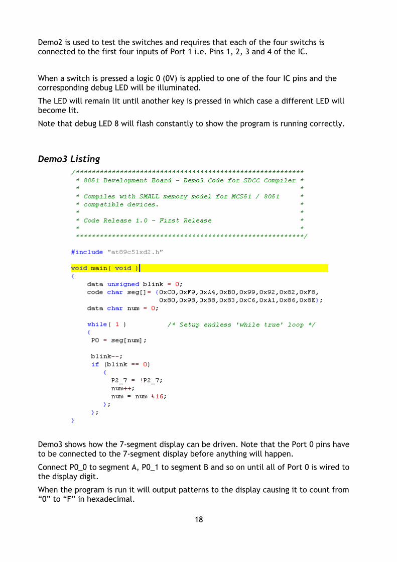
Demo3 Listing
Demo3 shows how the 7-segment display can be driven. Note that the Port 0 pins haveto be connected to the 7-segment display before anything will happen.
Connect P0_0 to segment A, P0_1 to segment B and so on until all of Port 0 is wired tothe display digit.
When the program is run it will output patterns to the display causing it to count from“0” to “F” in hexadecimal.
18

Demo4 Listing
Demo4 shows how to get very basic output to the serial port. Note that we have used nointerrupt driven routines or buffers so only one character can be sent at a time.
Further improvements would be to allow sending of strings, numbers and other datausing the printf and sprintf functions in the stdio.h library that comes with the compiler.
Although this is beyond the scope of this section there are details on the SDCC site forimplementing serial routines.
To allow you to see the serial data you will need to use a terminal program. You caneither use Hyperterminal that comes with Windows or the freeware terminal, notsurprisingly called “Terminal.exe”!, supplied on the CD.
Which ever program you use the serial communications are at 9600 baud with 8 databits, no parity and 1 stop bit (i.e. 9600,8,N,1). You should see 'U' characters appearingat the rate of about 2 a second.
Note that the supplied terminal program is particularly useful when you only have 1serial port as it can be set to automatically disconnect when you swap to using adifferent program. On the settings panel just ensure that the “Auto Dis/Connect”checkbox is ticked.
19

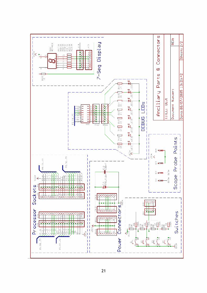
Circuit Schematics
20
21

Spares Parts
If you require any spare parts such as processor etc. they can be ordered through ourwebsite. We buy the components for the development kits in bulk so can obtain themmuch cheaper.
Spare PCBs are available if you wish to make your own boards as well as PSUs and cablesif you want to easily work on development boards in two different locations – just leavethe cable and PSU plugged into each PC!
22