Embed Size (px)
Citation preview

Start-Up 08/2003 Edition
sinumerikSINUMERIK 802S base line


SINUMERIK 802S base line
Start-Up
������������������������������������������������������������������������
Technical Manual
������������������
��
����������������������������������������������������������������������������������������������������
��
�����������������������������������������������������������������������������������������������������
������������������������������������������������������������������������������������������������������
Valid as from
Control system Software versionSINUMERIK 802S base line 4
2003.08 Edition
SINUMERIK 802S base lineControl System
Installing the control system 2
Installing the STEPDRIVE 3
Start-Up 4
Software Update
Technical Appendix 6
5
1
SINUMERIK Documentation
Key to editions
The editions listed below have been published prior to the current edition.
The column headed “Note” lists the amended sections, with reference to the previous edition.
Marking of edition in the “Note” column:
A ... ... New documentation.B ... ... Unchanged reprint with new order number.C ... ... Revised edition of new issue.
Edition Order No. Note
1999.02 6FC5597-2AA00-0BP1 A2002.01 6FC5597-2AA00-0BP2 C2003.08 6FC5597-4AA01-0BP0 C
Trademarks
SIMATIC®, SIMATIC HMI®, SIMATIC NET®, SIMODRIVE®, SINUMERIK®, and SIMOTION® are registeredtrademarks of SIEMENS AG.
Other names in this publication might be trademarks whose use by a third party for his own purposes may violatethe registered holder.
Copyright Siemens AG 2003. All right reserved
The reproduction, transmission or use of this document or its con-tents is not permitted without express written authority. Offenders willbe liable for damages. All rights, including rights created by patentgrant or registration of a utility model, are reserved.
Exclusion of liability
We have checked that the contents of this document correspond tothe hardware and software described. Nonetheless, differencesmight exist and we cannot therefore guarantee that they are com-pletely identical. The information contained in this document is re-viewed regularly and any necessary changes will be included in thenext edition. We welcome suggestions for improvement.
© Siemens AG, 2003Subject to technical changes without notice.
Siemens-Aktiengesellschaft. SINUMERIK 802S/802C base line
®

Safety notices This Manual contains notices intended to ensure your personal safety , as wellas to protect products and connected equipment against damage. Safetynotices are highlighted by a warning triangle and presented in the followingcategories depending on the degree of risk involved:
Danger
Indicates an imminently hazardous situation which, if not avoided, will result indeath or serious injury or in substantial property damage.
Warning
Indicates a potentially hazardous situation which, if not avoided, could result indeath or serious injury or in substantial property damage.
Caution
Used with safety alert symbol indicates a potentially hazardous situation which,if not avoided, may result in minor or moderate injury or in property damage.
Caution
Used without safety alert symbol indicates a potentially hazardous situationwhich, if not avoided, may result in property damage.
Notice
Indicates important information relating to the product or highlights part of thedocumentation for special attention.
Qualified person The unit may only be started up and operated by qualified person or persons.Qualified personnel as referred to in the safety notices provided in thisdocument are those who are authorized to start up, earth and label units,systems and circuits in accordance with relevant safety standards.
Proper use Please observe the following:
Warning
The unit may be used only for the applications described in the catalog or thetechnical description, and only in combination with the equipment, componentsand devices of other manufacturers as far as this is recommended or permittedby Siemens.
This product must be transported, stored and installed as intended, andmaintained and operated with care to ensure that it functions correctly andsafely.
!
!
!
!


Contents
SINUMERIK 802S base line IStart-Up
Contents
1. SINUMERIK 802S base line Control System 1-11.1 Components of the SINUMERIK 802S base line 1-11.2 Technical data 1-3
2. Installing the Control System 2-12.1 Installing and Dismantling the SINUMERIK 802S base line 2-12.2 Interfaces and cables 2-42.3 Connecting the individual components 2-7
2.3.1 Connecting the feed drives and the spindle (X7) 2-72.3.2 Connecting the measuring systems (X6) 2-10
2.3.3 Configuration of the RS232 interface connection (X2) 2-11 2.3.4 Connecting handwheels (X10) 2-13 2.3.5 Connecting BERO and NC-READY (X20) 2-14 2.3.6 Connecting the digital inputs (X100 ... X105) 2-16
2.3.7 Connecting the digital outputs (X200 ,X201) 2-18 2.4 Power Supply for CNC (X1) 2-20 2.5 LEDs and Other Elements on CNC 2-21
3. Installing the STEPDRIVE 3-13.1 Installing and dismantling the STEPDRIVE C/C+ drive modules 3-1
3.2 Cabling 3-3 3.3 Starting up the drive modules 3-5
4. Start-Up 4-1! 4.1 General 4-1 4.1.1 Access levels 4-2 4.1.2 Structure of machine data (MD) and setting data (SD) 4-3 4.1.3 Handling of machine data 4-4 4.1.4 Data saving 4-4 4.2 Turning on and booting the control system 4-6 4.2.1 Boot messages 4-8 4.3 Starting up the PLC 4-9 4.3.1 Commissioning of the PLC 4-9
4.3.2 Start-up modes of the PLC 4-11 4.3.3 PLC alarms 4-12 4.3.4 Machine control panel area layout 4-17 4.3.5 PLC programming 4-18 4.3.6 Instruction set 4-21 4.3.7 Program organization 4-27
4.3.8 Data organization 4-284.3.9 Interface to the control system 4-284.3.10 Testing and monitoring the user program 4-28
4.4 PLC applications “Download/Upload/Copy/Compare 4-29 4.5 User Interface 4-31 4.6 Technology Setting 4-31
4.7 Commissioning 4-324.7.1 Entering the general machine data 4-324.7.2 Starting up the axes 4-344.7.3 Starting up the spindle 4-444.7.4 Completing the Start-Up 4-494.7.5 Cycle start-up 4-504.8 Series machine start-Up 4-51
Contents
II SINUMERIK 802S base line Start-Up
5. Software Update 5-1 5.1 Updating the system software using a PC/PG 5-1 5.2 Update errors 5-2
6. Technical Appendix 6-16.1 List of machine and setting data 6-16.1.1 Display machine data 6-26.1.2 General machine data 6-46.1.3 Channel–specific machine data 6-56.1.4 Axis–specific machine data 6-66.1.5 Setting data 6-166.2 PLC user interface signals 6-176.2.1 Address ranges 6-176.2.2 Retentive data area 6-186.2.3 CNC signals 6-196.2.4 Channel signals 6-216.2.5 Axis/spindle signals 6-286.2.6 Signals from/to MMC 6-336.2.7 Machine control panel signals (MCP signals) 6-356.2.8 PLC machine data 6-366.2.9 User alarm 6-386.3 PLC user program for turning (SAMPLE) 6-406.3.1 Function 6-406.3.2 Input/output configuration 6-436.3.3 Definition of user keys 6-446.3.4 PLC machine data 6-466.3.5 SAMPLE program structure 6-506.3.6 User alarm 6-526.3.7 Start-Up of SAMPLE program 6-536.4 Unipolar spindle 6-55

SINUMERIK 802S base line 1-1Start-Up
SINUMERIK 802S base line 1Control System
1.1 Components of the SINUMERIK 802S base line
What is SINUMERIK 802S base line?
The SINUMERIK 802S base line is a microprocessor-controlled numericalcontrol system for economic machine tools with stepper motor drives.
Hardware components
The SINUMERIK 802S base line is a compact CNC unit. It consists of thefollowing areas (see figure 1-1):
NDQ!Bsfb
OD!Lfzt
MDE
Fyufsobm!tqjoemf!esjwf
Tufq!Esjwft
Tufq!npupst
Fig. 1-1 Components of SINUMERIK 802S base line (turning variant)
LCD
NC Keys
MCP Area
External spindle drive
Step motors
Step D
rives

SINUMERIK 802S base line Control System
1-2 SINUMERIK 802S base line Start-Up
Software components The SINUMERIK 802S base line comprises the following software components,
which can be ordered:
z System software on the permanent flash memory of the CNC
� Boot softwareloads the remaining system software from the permanent memoryinto the user memory (DRAM) and starts the system.
� MMC software (Man Machine Communication),implements all operating functions
� NCK software (NC Kernel)implements all NC functions. This software controls an NC channelwith a maximum of 3 movement axes and a spindle.
� PLC software (Programmable Logic Control)executes the integrated PLC user program cyclically.
� Integrated PLC user programintended to adjust the SINUMERIK 802S base line to the machinefunctions (see also Description of Functions “Integrated UserProgram for SINUMERIK 802S base line”).
z Toolbox
� WinPCIN transfer program for a PC/PG (programming device) totransfer user data and programs
� Text manager
� Cycle kit for loading into the control system using WinPCIN
� User program library
� Technological machine data files
� Programming tool
z Update diskettes
� Update program with operator prompting system
� 802S base line system software, packed, for loading and programmingthe SINUMERIK 802S base line via an update program.
User data User data are:
z Machine data
z Setting data
z Tool data
z R parameters
z Zero offsets
z Compensation data
z Part programs
z Standard cycles
Data saving Modified user data are saved for at least 50 h after power off or power failure.After then, they might get lost.
Warning
To avoid data loss, the operator must carry out data saving (see Section 4.1.4).!

SINUMERIK 802S base line Control System
SINUMERIK 802S base line 1-3Start-Up
1.2 Technical data
Connected load Table 1–1 Connected load
Parameter Min. Typ. Max. UnitSupply voltage 20.4 24 28.8 VRipple 3.6 VssCurrent consumption from 24 V 1.5 APower dissipation of CNC 35 WStart-up current 4 A
Weight Table 1–2 Weight
Component Weight [g]CNC 4500
Dimensions Table 1–3 Component dimensions
Component Dimensions LxWxD [mm]CNC 420 x 300 x 83
Environmental operating conditions
Table 1–4 Environmental operating conditions
ParameterTemperature range 0...55 °CPermissible relative humidity 5...95 % without condensationAir pressure 700...1,060 hPa
The operating conditions comply with IEC 1131–2.Installation in a housing (e.g. cubicle) is absolutely necessary for operation.
Transport and storage conditions
Table 1–5 Transport and storage conditions
ParameterTemperature range Transport: –40...70 °C
Storage: -20 ... 55 °CPermissible relative air humidity 5...95 % without condensationAir pressure 700...1,060 hPaTransport height –1,000...3,000 mFree fall in transport package ≤1,200 mm
Protective quality and degree of protection Class of protection I to IEC 536.
No PE terminal required.
Foreign matter and water protection to IEC 529.
For CNC:IP 54 front IP 00 rear

SINUMERIK 802S base line Control System
1-4 SINUMERIK 802S base line Start-Up

SINUMERIK 802S base line 2-1Start-Up
Installing the Control System 2
2.1 Installing and Dismantling the SINUMERIK 802S base line
Warning
Do not install when the equipment is under power!
The modules contain electrostatically sensitive devices.It must be ensured that persons without ESD protection never touch printedcircuit boards or components when handling operator and machine controlpanels.
Approach Due to the compactness, it is very convenient to install and dismantle thecontrol system.
1. Fix the system in the machine control station.
2. Screw the system in place with 8 M4 x 16 assembled screws. Themaximum allowed torque for the screws is 1.5 Nm.
Notice
Prior to installation, the machine control panel can be provided with anemergency stop button. If it is not required, the opening must be covered withthe supplied self-adhesive cover.
Dismantling the control system
The control system is dismantled as described above in the reverse order.
Warning
Do not dismantle when the equipment is under power!
!
!

Installing the Control System
2-2 SINUMERIK 802S base line Start-Up
Mounting dimensions The dimensions shown below are important for installing the control system:
Fig. 2-1 Mounting dimensions for 802S base line

Installing the Control System
SINUMERIK 802S base line 2-3Start-Up
1) Thread plugging M4 or ø5 hole (8x)
Fig. 2-2 Mounting dimensions for 802S base line

Installing the Control System
2-4 SINUMERIK 802S base line Start-Up
2.2 Interfaces and cables
Position of the interfaces and elements
Fig. 2-3 Rear of CNC system
Interfaces CNC
z X1 power supply terminals (DC24V)
3-pin screw-type terminal block for connecting the 24 V load powersupply
z X2 RS232 interface (V24)
9-pin sub-D plug connector
z X6 spindle interface (ENCODER)
15-pin sub-D socket for connecting a spindle incremental positionencoder(RS422)
z X7 drive interface (AXIS)
50-pin sub-D socket connector for connecting the power sections for amaximum of four analog drives including spindle
z X10 handwheel interface (MPG)
10-pin front connector for connecting the handwheels
z X20 digital inputs (DI)
10-pin front connector for connecting BERO proximity switches
Installing the Control System
SINUMERIK 802S base line 2-5Start-Up
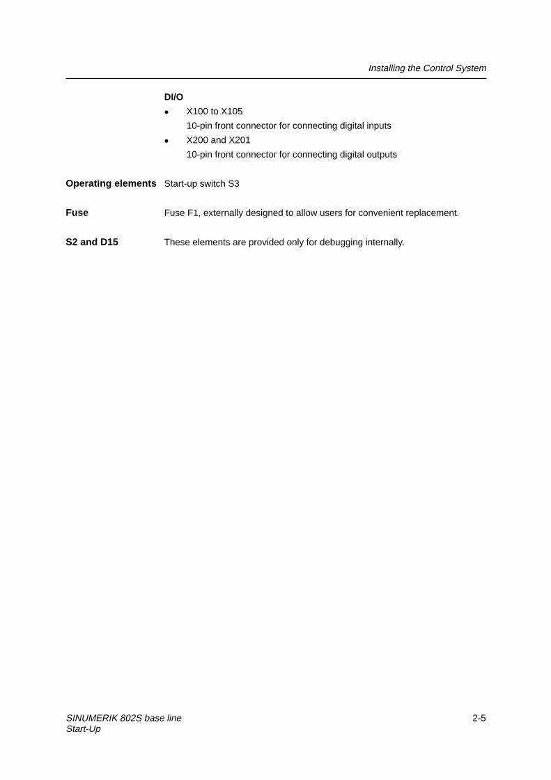
DI/O
z X100 to X105
10-pin front connector for connecting digital inputs
z X200 and X201
10-pin front connector for connecting digital outputs
Operating elements Start-up switch S3
Fuse Fuse F1, externally designed to allow users for convenient replacement.
S2 and D15 These elements are provided only for debugging internally.

Installing the Control System
2-6 SINUMERIK 802S base line Start-Up
Connecting cables The components are wired up as shown in the Connection Diagram 2–4. Forthe cables required, please refer to the diagram below.
&1&
',
VSLQGOH
GULYH
VSLQGOH
PRWRU HQFRGHU
+DQGZKHHO�����
%(52
�����
6LJQDO������
/RDG������
�);������&'�������
�);������%%�������
�);������$'�������
ZLUH �����������PP��
'&��9
56���
$;,6�63,1'/(
(1&2'(5
03*
%(52
,1
0
,1
0
3��
287
0
3��
0;�
;�
;��
;��
;���
;���
;���
;�
�);������$$�������
;� FRPPXQLFDWLRQ
ZLWK�FRPSXWHU56���
,VRODWRU
RSWLRQ �);������'6��
�);������$$�������
6WHSGULYH�&�&��)0�6WHSGULYH
VWHS
PRWRU
���������
���������
���������
���������
���������
���������
;���
;���
;���
;���
;���
'2
���������
���������
ZLUH ����������PP��
ZLUH �����������PP��
ZLUH �����������PP��
��9'&
��3��0
��9'&
��3��0
Fig. 2-4 Connection Diagram for SINUMERIK 802S base line

Installing the Control System
SINUMERIK 802S base line 2-7Start-Up
2.3 Connecting the individual components
Connecting the components
Please note the following:
Notice
Use only shielded cable and make sure that the shield is connected to themetal or metal plated connector casing on the control side. For the purpose ofisolating the analog setpoint signal from low-frequency interference, werecommend not to ground the shield on the drive side.
The preassembled cable offered as accessories provides optimum protectionagainst interference.
General procedure:
Proceed as follows to connect the individual components:
1. Connect the cables to the components as shown in Fig. 2–3.
2. Fix the sub-D connector in place using the knurled screws.
2.3.1 Connecting the feed drives and the spindle (X7)
Pin assignments For connector on the CNC side Feed drive interface
Connector designation: X7 AXIS 1–4
Connector type: 50-pin sub-D plug connector
Table 2-1 Pin assignments of connector X7
X7Pin Signal Type Pin Signal Type Pin Signal Type1 n.c. 18 ENABLE1 O 34 n.c. AO2 n.c. 19 ENABLE1_N O 35 n.c. AO3 n.c. 20 ENABLE2 O 36 n.c. AO4 AGND4 AO 21 ENABLE2_N O 37 AO4 AO5 PULS1 O 22 M VO 38 PULS1_N O6 DIR1 O 23 M VO 39 DIR1_N O7 PULS2_N O 24 M VO 40 PULS2 O8 DIR2_N O 25 M VO 41 DIR2 O9 PULS3 O 26 ENABLE3 O 42 PULS3_N O10 DIR3 O 27 ENABLE3_N O 43 DIR3_N O11 PULS4_N O 28 ENABLE4 O 44 PULS4 O12 DIR4_N O 29 ENABLE4_N O 45 DIR4 O13 n.c. 30 n.c. 46 n.c.14 n.c. 31 n.c. 47 n.c.15 n.c. 32 n.c. 48 n.c.16 n.c. 33 n.c. 49 n.c.17 SE4.1 K 50 SE4.2 K

Installing the Control System
2-8 SINUMERIK 802S base line Start-Up
Signal Description
Stepper Interface
PULSn; PULSn_N Stepper Clock
DIRn; DIRn_N Stepper Revolution Direction
ENABLEn; ENABLEn_N Stepper Enable
M Ground (not to be connected when using differential signals)
Analog Spindle Interface
Aon Analog Command Value
AGNDn Analog Ground
SEn.1; SEn.2 Servo Enable Relay
n = 1...4 Number of Axis
Signal Specification: +/-10V for Analog Outputs
RS422 for Stepper Signals
Axis assignment
1 X axis2 Y axis3 Z axis4 Spindle
Table 2–2 Cable assignment (for type 6FX2 002-3AD02)
CNC Side Cable Drive SidePIN Core Color Signal Name PIN
5 black P138 brown P1N6 red D139 orange D1N18 yellow E119 green
1st axis
E1N40 White/grey P27 Brown/black P2N41 Blue D28 Violet D2N20 Grey E221 White
2nd axis
E2N9 white/black P342 white/brown P3N10 brown/red D343 brown/orange D3N26 White/red E327 White/orange
3rd axis
E3N17 White/yellow 950 White/green 654 White/blue 14
1
17
1834
3350
37 White/violet
Spindle
56

Installing the Control System
SINUMERIK 802S base line 2-9Start-Up
Drives with analog interface Signals:
A voltage and an enable signal are output.
z AOn (SETPOINT)
Analog voltage signal in the range ± 10 V to output a speed setpoint
z AGNDn (REFERENCE SIGNAL)
Reference potential (analog ground) for the setpoint signal, internallyconnected to logic ground.
z SEn (SERVO ENABLE)
Relay contact pair controlling the enable of the power section, e.g. of a stepdrive unit controlled via a PLC program.
Signal parameters
The setpoint is output as an analog differential signal.
Table 2–3 Electrical parameters of the signal outputs for step-switching drives
Parameter Min Max UnitVoltage range –10.5 10.5 VOutput current –3 3 mA
Relay contact
Table 2–4 Electrical parameters of the relay contacts
Parameter Max. UnitSwitching voltage 50 VSwitching current 1 ASwitching power 30 VA
Cable length: max. 35 m

Installing the Control System
2-10 SINUMERIK 802S base line Start-Up
2.3.2 Connecting the spindle measuring system (X6)
Pin assignment of the connector on the CNC side Measuring system interface (incremental encoder)
Connector designation: X6 ENCODER
Connector type: 15-pin sub-D plug connector
Table 2–5 Pin assignment of the female connector X6
Pin Signal Type Pin Signal Type
1 n.c. 9 M VO2 n.c. 10 Z I3 n.c. 11 Z_N I4 P5_MS VO 12 B_N I5 n.c. 13 B I6 P5_MS VO 14 A_N I7 M VO 15 A I8 n.c.
1
8
9
15
Signal names Description
A; A_N Track A
B; B_N Track B
Z; Z_N Zero Reference Mark
P5_MS +5,2V Supply Voltage
M Ground
Signal Specification: RS422
Signal type
VO Voltage output (supply)I 5V input (5V signal)
Connectable encoder types
Incremental 5 V encoders can be connected directly.
Characteristics The encoders must meet the following requirements:
Transmission method: Differential transmission with 5 V square-wave signals
Output signals: Track A as true and negated signal (Ua1, Ua1 )
Track B as true and negated signal (Ua2, Ua2 )
Zero signal N as true and negated signal (Ua0, Ua0 )
Max. output frequency: 1.5 MHz
Phase offset between
tracks A and B: 90º ± 30º�
Current consumption: max. 300 mA

Installing the Control System
SINUMERIK 802S base line 2-11Start-Up
Cable lengths The maximum cable length depends on the specifications of the encoderpower supply and on the transmission frequency.
To provide fault-free operation, make sure that the following values are notexceeded when using preassembled interconnecting cables from SIEMENS:
Table 2–6 Maximum cable lengths depending on the encoder power supply
Supply Voltage Tolerance Current Consumption Max. CableLength
5 V DC 4.75 V...5.25 V < 300 mA 25 m5 V DC 4.75 V...5.25 V < 220 mA 35 m
Table 2–7 Maximum cable lengths depending on the transmission frequency
Encoder Type Frequency Max. Cable Length1 MHz 10 mincremental500 kHz 35 m
2.3.3 Configuration of the RS232 interface connection (X2)
Pin assignment of connector on the CNC side
RS232 interface
Connector designation: X2 RS232
Connector type: 9-pin sub-D plug connector
Table 2–8 Pin assignment of connector X2
Pin Name Type Pin Name Type1 6 DSR I2 RxD I 7 RTS O3 TxD O 8 CTS I4 DTR O 95 M VO
1
5
6
9
Signal description:
RxD Receive Data
TxD Transmit Data
RTS Request to sendCTS Clear to send
DTR Data Terminal Ready
DSR Data Set Ready
M Ground
Signal level
RS232

Installing the Control System
2-12 SINUMERIK 802S base line Start-Up
Signal type
I InputO OutputVO Voltage output
Cable for WinPCIN Table 2–9 Cable for WinPCIN: Pin assignment of the Sub-D connector
9-Pin Name 25-Pin1 Shield 12 RxD 23 TxD 34 DTR 65 M 76 DSR 207 RTS 58 CTS 49
or
9-Pin Name 9-Pin1 Shield 12 RxD 33 TxD 24 DTR 65 M 56 DSR 47 RTS 88 CTS 79
��� 6�&�EDVH�OLQH��SLQ�6XE�'
R xD 2T xD 3D T R 40 V 5D S R 6
T xD3R xD2D S R60 V5D T R4
0 .1 m m 2
R T S 7 C T S8C T S 8 R T S7
R xD 2T xD 3D T R 40 V 5D S R 6
R xD2T xD3D S R60 V7D T R2 0
0 .1 m m 2
R T S 7 C T S5C T S 8 R T S4
3&��SLQ�6XE�'
��� 6�&�EDVH�OLQH 3&
��SLQ�6XE�' ���SLQ�6XE�'
Fig. 2-5 Communication connector RS232(X2)

Installing the Control System
SINUMERIK 802S base line 2-13Start-Up
2.3.4 Connecting handwheels (X10)
Pin assignment of connector on the CNC side Handwheel interface
Connector designation: X10MPG
Connector type: 10-pin mini–Combicon plug connector
Table 2–10 Pin assignment of connector X10
X10Pin Name Type
1 A1 I2 A1_N I3 B1 I4 B1_N I5 P5_MS VO6 M5_MS VO7 A2 I8 A2_N I9 B2 I10 B2_N I
1
10
Signal names
A1, A1_N Track A, true and negated (handwheel 1)B1, B1_N Track B, true and negated (handwheel 1)A2, A2_N Track A, true and negated (handwheel 2)B2, B2_N Track B, true and negated (handwheel 2)P5_MS 5.2 V supply voltage for handwheelsM Supply ground
Signal level
RS422
Signal type
VO Voltage outputI Input (5 V signal)
Handwheels Two electronic handwheels can be connected which must meet the followingrequirements:
Transmission method: 5 V square-wave (TTL level or RS422)
Signals: Track A as true and negated signal (Ua1, Ua1 )
Track B as true and negated signal (Ua2, Ua2 )
Max. output frequency: 500 kHz
Phase offset betweentracks A and B: 90�� ± 30�
Supply: 5 V, max. 250 mA

Installing the Control System
2-14 SINUMERIK 802S base line Start-Up
2.3.5 Connecting BERO and NC-READY (X20)
Pin assignment of connector on the CNC side BERO input interface
Connector designation: X20 DI
Connector type: 10-pin plug connector
Table 2–11 Pin assignment of connector X20
X20Pin Signal Type
1 NCRDY_1 K2 NCRDY_2 K3 I0 / BERO1 DI4 I1 / BERO2 DI5 I2 / BERO3 DI6 I3 / BERO4 DI7 I4 / MEPU1 Not defined8 I5 / MEPU2 Not defined9 L- VI10 L- VI
11
20
Signal description:
NCRDY_1…2 NC-READY-Contact, max. current is 2A at 150VDC or125VAC)
I0 ... I5 Fast digital input 0 … 5BERO1 ... BERO4 BERO-Input for axis 1 ... 4
L- Reference potential for digital input
Signal type
K Switching contact
4 BERO inputs These inputs are 24V P-switching. Switches or non-contact sensors, e.g.inductive proximity switches(BERO) can be connected.
They can be used as switches for reference points, for example:
BERO1 – X axis
BERO2 – Z axis
Table 2-12 Electrical parameters of the digital inputs
Parameter Value Unit Note“1” signal, voltage range 11…30 V“1” signal, current consumption 6…15 mA“0” signal, voltage range -3…5 V Or input openSignal delay 0Æ1 15 usSignal delay 1Æ0 150 us
NC–READY output Readiness in the form of a relay contact (NO); must be integrated into theEMERGENCY STOP circuit.

Installing the Control System
SINUMERIK 802S base line 2-15Start-Up
Table 2–13 Electrical parameters of the NCREADY relay contact
Parameter Max. UnitDC switching voltage 50 VSwitching current 1 ASwitching power 30 VA
2
1
P in num ber ofX 20
1P5
N C_R D Y
R elay
Fig. 2-5
The NCREADY is an internal relay of NC. It will open when NC is not ready,and close after NC is ready for operation.

Installing the Control System
2-16 SINUMERIK 802S base line Start-Up
2.3.6 Connecting the digital inputs (X100 ... X105)
Pin assignment for connector
Interface for the digital inputs
Connector designation: X100, X101, X102, X103, X104, X105IN
Connector type: 10-pin plug connector
Table 2–14 Connector pin assignment
X100Pin Name Type1 n.c.2 DI0 DI3 DI1 DI4 DI2 DI5 DI3 DI6 DI4 DI7 DI5 DI8 DI6 DI9 DI7 DI
10 M VI
X100
01234567M
X101Pin Name Type1 n.c.2 DI8 DI3 DI9 DI4 DI10 DI5 DI11 DI6 DI12 DI7 DI13 DI8 DI14 DI9 DI15 DI
10 M VI
X101
89
101112131415
M
X102Pin Name Type1 n.c.2 DI16 DI3 DI17 DI4 DI18 DI5 DI19 DI6 DI20 DI7 DI21 DI8 DI22 DI9 DI23 DI
10 M VI
X102
1617181920212223
M

Installing the Control System
SINUMERIK 802S base line 2-17Start-Up
X103Pin Name Type1 n.c.2 DI24 DI3 DI25 DI4 DI26 DI5 DI27 DI6 DI28 DI7 DI29 DI8 DI30 DI9 DI31 DI
10 M VI
X103
2425262728293031
M
X104Pin Name Type1 n.c.2 DI32 DI3 DI33 DI4 DI34 DI5 DI35 DI6 DI36 DI7 DI37 DI8 DI38 DI9 DI39 DI
10 M VI
X104
3233343536373839
M
X105Pin Name Type1 n.c.2 DI40 DI3 DI41 DI4 DI42 DI5 DI43 DI6 DI44 DI7 DI45 DI8 DI46 DI9 DI47 DI
10 M VI
X105
4041424344454647
M
Signal names
DI0...47 24 V digital inputs
Signal type
VI Voltage inputDI Input (24 V signal)
Table 2–15 Electrical parameters of the digital inputs
Parameter Value Unit Note“1” signal, voltage range 15...30 V“1” signal, current consumption 2...15 mA“0” signal, voltage range –3...5 V or input openSignal delay 0 Æ 1 0.5...3 msSignal delay 1 Æ 0 0.5...3 ms

Installing the Control System
2-18 SINUMERIK 802S base line Start-Up
2.3.7 Connecting the digital outputs (X200 ,X201)
Connector pin assignment Interface for digital outputs
Connector designation: X200, X201OUT
Connector type: 10-pin plug connector
Table 2–16 Connector pin assignment
X200Pin Name Type1 1P24 VI2 DO0/CW O3 DO1/CCW O4 DO2 O5 DO3 O6 DO4 O7 DO5 O8 DO6 O9 DO7 O
10 M VI
X200
0/CW
1/CCW
234567M
1P24
X201Pin Name Type1 2P24 VI2 DO8 O3 DO9 O4 DO10 O5 DO11 O6 DO12 O7 DO13 O8 DO14 O9 DO15 O
10 M VI
X201
89
101112131415
M
2P24
Signal Description:
DO0 ... DO15 Digital output 0...15, Max. current 500mA.
DO0/ CW Digital output 0 / Unipolar Spindle CW Direction, Max.
current 500mA.
DO1/ CCW Digital output 1 / Unipolar Spindle CCW Direction, Max. current 500mA.1P24, M Power supply for the digital outputs 0...7
2P24, M Power supply for the digital outputs 8...15
Signal type
VI Voltage inputO Output (24 V signal)

Installing the Control System
SINUMERIK 802S base line 2-19Start-Up
Table 2–17 Electrical parameters of the digital outputs
Parameter Value Unit Note“1” signal, nominal voltageVoltage drop
24max. 3
VV
“1” signal, output current 0.5 A Simultaneity factor0.5 per 16 outputs
“0” signal, leakage current max. 2 mA

Installing the Control System
2-20 SINUMERIK 802S base line Start-Up
2.4 Power Supply for CNC (X1)
Screw-terminal block
The 24 V DC load power supply unit required for supplying CNC is connectedto screw- type terminal block X1.
Characteristics of the load power supply The 24 V DC voltage must be generated as a functional extra-low voltage with
safe electrical Isolation (to IEC 204–1, Section 6.4, PELV).
Table 2–18 Electrical parameters of the load power supply
Parameter Min. Max. Units ConditionsVoltage range mean value 20.4 28.8 VRipple 3.6 VssNon-periodic overvoltage 35 V 500 ms cont.
50 s recoveryRated current consumption 1.5 AStarting current 4 A
Pin assignment on the CNC side Table 2–19 Pin assignment of screw terminal block X1
Terminal1 PE PE2 M Ground3 P24 DC 24 V

Installing the Control System
SINUMERIK 802S base line 2-21Start-Up
2.5 LEDs and Other Elements on CNC
Error and status LEDs
There are three LEDs on the front panel of the CNC.
Fig. 2-6 Operator panel and user interfaces
ERR (red) Group error
This LED indicates an error condition of the CNC.
POK (green) Power OK
The power supply is ready.
DIA (yellow) Diagnostics
This LED indicates various diagnosis states. Under normal operatingconditions, this LED flashes 1:1.

Installing the Control System
2-22 SINUMERIK 802S base line Start-Up
Start-up switch (S3) This rotary switch is intended to assist start-up.
Position 0: Normal operation
Positions 1–4:Start-up
cf. also Section 4.2, Table 4–2
Fuse (F1) This design allows users to replace the fuse very conveniently when the fuse isbroken.
S2 and D15 They are provided only for debugging internally.
Grounding Screw In order to ensure the system functions correctly and safely, the CNC must begrounded through the grounding screw on the rear side of CNC.

SINUMERIK 802S base line 3-1Start-Up
Installing the STEPDRIVE 3
General The SINUMERIK802S base line can be configured with STEPDRIVE C/C+ orFM STEPDRIVE. For the detailed description of FM STEPDRIVE, please referto the document on DOConCD (ordering number: 6FC5298-0CD00-0BG0).
3.1 Installing and dismantling the STEPDRIVE C/C+ drive modules
Warning
Before installing the STEPDRIVE C/C+ drive modules, first always make surethat the equipment is disconnected from the mains.
Installation To install the drive modules, proceed as follows (see Fig. 3–1):
1. Screw in the upper fastening screws M5 with washer and lock washer.
2. Hang the module into the clips of the upper fastening bracket.
3. Screw in the lower fastening screws and tighten all screws.
Notice
The modules should be installed such that a clearance of at least 10 cm is leftabove, below and between the modules (dimension “a”).
The drive modules, however, can be mounted directly side by side (a> 10 mm)provided they are ventilated with an air stream greater than / equal to 1 m/s.
Do not install devices which are strongly heated during operation beneath thedrive modules!
Dismantling The drive modules are dismantled in the reverse order.
Warning
When removing the drive modules, always first make sure that the system isdisconnected from the mains!
!

Installing the STEPDRIVE
3-2 SINUMERIK 802S base line Start-Up
Mounting Dimensions
3412
90 a
Washer, lock washer
286
307
7
>80
≥100
Fig.3-1 Mounting dimensions

Installing the STEPDRIVE
SINUMERIK 802S base line 3-3Start-Up
3.2 Cabling
Cable overview Connect the STEPDRIVE C/C+ drive modules, the BYG stepper motors andthe SINUMERIK 802S base line control system as shown in Fig. 3–2:
AABBCCDDEEPE
R D YT M PF LTD IS
C U R R .1C U R R .2R ES .D IR .
+P U LS-PU LS+D IR-D IR+E N A-EN A R D Y Z P H+24V 24V G N D P E
LNP E
AABBCCDDEEPE
R D YT M PF LTD IS
C U R R .1C U R R .2R ES .D IR .
+P U LS-PU LS+D IR-D IR+E N A-EN A R D Y Z P H+24V 24V G N D P E
LNPE
D rive o f axis 1 D rive o f axis 2
S IN U M E R IK 8 0 2Sb a se lin e
X7
Mot
or c
able
ye llowwh iteb lueredorangegreengrayb lackbrownpurp le
P 1P 1ND 1D 1NE 1E 1N
P2P2ND 2D 2NE2E2N
Mot
or c
onne
ctio
n an
al.
to a
xis
1
yello
w
blue
whi
te
red
oran
gegr
een
gray
blac
kbr
own
purp
le
M o to r
230V A C
L
N
P E
230 /85 V A C trans fo rm er
Qsfbttfncmfe dbcmf
7GY3113.4BE13.2 yy1
Fig.3-2 Overview of cables
Warning
Prior to performing connection work, always first make sure that the supplyvoltage is switched off.
With the supply voltage switched off, hazardous voltages are present at themains and motor connections. Under no circumstances may these connectionbe touched in the ON condition; otherwise, loss of life or severe personal injurycould be the consequence.
!
Preassembled cable6FX2002-3AD02-1xx0

Installing the STEPDRIVE
3-4 SINUMERIK 802S base line Start-Up
Mains connectionz The device must be connected via an external fuse.
Fuse: K6A for 1 axis
K10A for max. 2 axes
z If the transformer possesses a shielded winding, this should beconnected with low inductivity to PE.
z Ground the transformer on the secondary side.
Connecting the motor-end cablesz To connect the cables, remove the terminal box cover (3 screws).
z Use the cable with the order no. 6FX6 002–5AA51–.....
z On the drive end, connect the cable shield to the housing such that anelectrical connection is provided via the appropriate strain relief clampand clamp the braided shield to PE.
z On the motor side, braid the shield, provided it with a cable shoe andclamp it to the grounding screw.
Pulse interfacez To connect the drive pulse interface to the SINUMERIK 802S base line,
use the preassembled cable, order no.6FX2 002–3AD02–1xx0.
z On the drive side, connect the cable shield to the housing such that anelectrical connection is provided via the appropriate strain relief clamp.
24V signal interface To evaluate the 24 V high–side signals “Zero Phase” (ZPM) and/or “Driveready” (RDY) in the CNC, then connect a 24 V voltage (PELV) to the +24 V and24 V GND terminals.

Installing the STEPDRIVE
SINUMERIK 802S base line 3-5Start-Up
3.3 Starting up the drive modules
Prerequisite
z Proper connection of the cables as shown in Fig. 3–2.
z Setting of the current in accordance with the motor type using the DILswitch
C U R R .1
C U R R .2
R E S.
D IR
O N
R D YT M PF LTD IS
LE D s
D IP sw itch
M otor T ype C U R R 1 C U R R 2 P hase C urr
3 .5 N m
9 N m
12 N m
O F F
O F F
1.35 A
2.00 A
1.35 A
2.55 A
O F F
O F F
O F F
O N O N
O N
6 N m
1 8 N m
25 N m
O F F
O N
O N
O N
3.6 A
5.00 A
S T EP D R IV E C
S T EP D R IV E C +
S tepper D river
Warning
If the current is set too large for the motor, the motor can be damaged due toovertemperature.
Start-up sequence1. Connect the mains voltage and - if necessary - also the 24 V supply
voltage.
2. Check the DIS LED.
3. Activate the ENABLE signal via the control system (power-up the controlsystem).
The yellow DIS LED goes out and the green RDY LED is lit. The drive is ready,the motor is powered.
If the PULSE signal is provided by the control system with pulses, thenmotor will rotate in the direction of rotation specified by the DIR signal.
Notice
The DIP switch can be used to adapt the direction of rotation to the mechanicsof the machine. Never actuate the switch when the drive is powered!
!

Installing the STEPDRIVE
3-6 SINUMERIK 802S base line Start-Up
3.4 Error messages and error elimination
LEDName Color
Meaning Remedy
RDY green the only LEDthat is lit
Drive ready If the motor does not rotate, it canhave the following causes:- No pulses are output by the
control system.- Pulse frequency too high
(motor is “out of step”)- Motor load too large or
sluggishDIS yellow the only LED
that is litDrive ready; motor not powered Activate ENABLE signal via CNC
FLT red is lit There is one of the followingerrors:- Overvoltage or undervoltage- Short-circuit between the
motor phases- Short-circuit between motor
phase and ground
Measure 85 V operating voltageCheck cable connections
TMP red is lit Overtemperature in the drive Drive defective; replaceall No LED is lit No operating voltage Check cable connections

SINUMERIK 802S base line 4-1Start-Up
Start-Up 4
4.1 General
Start–up requirements
z The following is required:
� User Manual: Operation and Programming, SINUMERIK 802S baseline
� PC/PG (programming device) only for data saving and series start–up
� Toolbox on CD. The CD is either supplied with the control system orcan be ordered separately.
Contents
� WINPCIN for data transfer via the V24 interface from/to externalPC/PG
� Cycle pack Turning and Milling
z The mechanical and electrical installation of the equipment must becompleted.
Notice
For installation refer to the installation notes provided in the section 2.
z The control system with its components has powered up without errors.
Start–up sequence The SINUMERIK 802S base line can be strated up as follows:
1. Check whether the ENC has powered up.
2. PLC start-up
3. Technology setting
4. Set general machine data.
5. Set axis/machine–specific machine data.
� Match encoder with spindle
� Match setpoint with spindle
6. Dry run for axes and spindle(s)
7. Drive optimization
8. Complete start-up, data saving

Start-Up
4-2 SINUMERIK 802S base line Start-Up
4.1.1 Access levels
Protection levels The SINUMERIK 802S base line provides a protection level concept forenabling data areas. The protection levels range from 0 to 7 whereby 0 is thehighest and 7 the lowest level.
The control system comes with default passwords for protection levels 2 and 3.If necessary these passwords can be changed by the appropriate authorizedperson.
Table 4–1 Protection level concept
ProtectionLevel Disabled via Data Area
0 Siemens, reserved1 Siemens, reserved2 Password: EVENING (default) Machine manufacturer3 Password: CUSTOMER (default) Authorized operator, setter4 No password or
user IS from PLC → NCKAuthorized operator, setter
5 User IS from PLC → NCK6 User IS from PLC → NCK7 User IS from PLC → NCK
Protection levels 2 ... 3 The protection levels 2 and 3 require a password. The passwords can be
changed after activation. For example, if the passwords are no longer known,the control system must be reinitialized (booting in Start–Up Switch position1). This will reset all passwords to the default settings for this software version.
If the password is deleted, protection level 4 is applicable.
The password remains set until it is reset using the Delete password softkey;POWER ON will not reset the password.
Protection levels 4 ... 7 Protection level 4 is automatically set when no password is entered. If required,
the protection levels 4 ... 7 can be set from the user program via the userinterface.
See Section 6.1.1 “Display Machine Data”.
Notice
How to set the access levels is described in the User’s Guide “Operation andProgramming”.

Start-Up
SINUMERIK 802S base line 4-3Start-Up
4.1.2 Structure of machine data (MD) and setting data (SD)
Number and name Machine data (MD) and setting data (SD) are differed either by numbers ornames. Both the number and the name are displayed on the screen.Parameters:
z Activation
z Protection level
z Unit
z Standard value
z Range of values
Activation The activation levels are listed according to their priority. Any data changescome into effect after:
z POWER ON (po) switching on/off the SINUMERIK 802S base line
z NEW_CONF (cf)
� Activate MD softkey on the operator panel
� RESET key on the operator panel
� Modifications at the block limits are possible while the program isrunning.
z RESET (re) RESET key on the operator panel or M2/M30 at the end ofthe program
z IMMEDIATELY (im) after entering a value
Protection level To display machine data, protection level 4 (or higher) must be activated.
Start–up or machine data input generally requires protection level 2 or higher(password “EVENING”).
Unit Depending on the MD SCALING_SYSTEM_IS_METRIC, the physical units ofthe MD are set as follows:
MD10240 = 1 MD10240 = 0Mm inmm/min in/minm/s2 in/s2
m/s3 in/s3
mm/rev in/rev
If no physical units are applicable to the MD, the field contains a “–”.
Notice
The default setting of the machine data isMD10240 SCALING_SYSTEM_IS_METRIC = 1 (metric).
Default data This is the default value for the machine or setting data.

Start-Up
4-4 SINUMERIK 802S base line Start-Up
Range of values (minimum and maximum values)
... specifies the input limits. If no range of values is specified, then the inputlimits are defined by the data type, and the field is marked with “***”.
4.1.3 Handling of machine data
Handling methodsz Display
z Input via keys and V24 interface
z Making backup copies and reading in/reading out data via the V24interface
These back-up copies contain
� machine data
� line check sums and
� machine data numbers.
Aborting when loading MD If incorrect machine data files are read into the control system, an alarm is
output.
At the end of reading, an alarm with the number of errors is displayed.
4.1.4 Data saving
Internal data saving The data in the memory backed up for a limited period can be saved internallyin the permanent memory of the control system.
An internal data backup should be carried out if the control system has beenswitched off for more than 50 hours (at least 10 min/day with controller ON).
It is recommended to carry out internal data saving whenever important datachanges have been made.
Notice
During the internal data backup, a memory copy of the memory backed up fora limited time is made and stored in the permanent memory. Selective databackup (e.g. only the machine data and not the part programs) is not possible.
Saving data internally:
Use the ETC key to extend the menu in the Diagnosis/Start–up menu andpress the Save data softkey.
Loading data from an internal data backup:
Boot the control system using the start–up switch, position 3

Start-Up
SINUMERIK 802S base line 4-5Start-Up
If the data in the backed–up memory area is lost, on POWER ON the datasaved in the permanent memory area are automatically reloaded into thememory.
Notice
The note “4062 Data backup copy has been loaded” appears.
External data saving In addition to the internal data backup, the user data of the control system canand must also be saved externally.
External data saving requires a PC/PG (programming device) with V24interface and the WinPCIN tool (included in the tool box).
External data saving should be performed whenever substantial changes in thedata have been made, as well as always at the end of start–up.
External data backup variants:
Saving data externally:
1. The data record is read out completely, creating the series start-up file.This is intended for series start-up or to restore the control system statusafter replacing hardware components or after data loss.
2. Files are read in or read out by areas. The following user data can beselected as individual files:
Data
� Machine data
� Setting data
� Tool data
� R parameters
� Zero offset
� Compensation data (LEC)
Part programs
Standard cycles
Saving data externally:
Use the Services/Data outp. menu to transfer the following user data asindividual files to an external PC via the V24 interface.
Loading data from an external data backup into the control system:Press the Start data inp. softkey in the Services menu.

Start-Up
4-6 SINUMERIK 802S base line Start-Up
4.2 Turning on and booting the control system
Procedure
z Inspect the system visually for:
� proper mechanical installation with tight electrical connections
� supply voltages
� connections for shielding and grounding.
z Turn on the control system.
Notice
Providing memory and start–up switch S3 are set correctly (see Fig.2–6), thecontrol system boots.
Start–up switch S3 (hardware) The CNC is provided with a start–up switch to assist start–up of the control
system.
This switch can be actuated using a screw driver.
Table 4–2 Start–up switch settings
Position Meaning0 Normal power-up1 Power-up with default machine data (user data determined by the
software version)2 System software update3 Power-up with saved data4 PLC stop5 Reserve6 Assigned7 Assigned
The switch position comes into effect with next power-up and is displayed onthe screen when the control system powers up.
Start–up switch (software) In addition to the hardware start–up switch, the following functions can also be
carried out in the Diagnosis/Start–up/Start–up switch menu:
z Normal boot (Start–up switch position 0)
z Boot with default machine data (Start–up switch position 1)
z Boot with saved data (Start–up switch position 3)
These power-up functions have a higher priority than the hardware start-upswitch.
Booting the control system When the control system is turned on for the first time, an initial state of the
control system is established automatically. All memory areas are initializedand are loaded with previously stored default data.
The PLC area of retentive bit memories is explicitly erased.

Start-Up
SINUMERIK 802S base line 4-7Start-Up
The control system changes to the JOG/Ref.point approach mode and theyellow LED DIAG flashes (see Fig. 2–6).
This initial state is the precondition for error–free start–up of the controlsystem.
When the control system is already turned on, start–up is also possible in theDiagnosis menu (see User Manual).
Normal booting (Start-up switch position 0)
ResultUser data exist, noboot error
Control system changes toJOG/Ref.point approach mode,yellow LED DIAG (see Fig. 4–1) flashes.
Data in user memoryfaulty
Backed–up user data are loaded from the permanentmemory into the user memory (as in start–up switchposition 3). If no valid user data are in the permanentmemory, the default data are loaded (as in start–upswitch position 1).Any deviations from normal booting are displayed onthe screen.
Booting with default machine data (Start–up switch position 1)
ResultThe user memory area not loaded with default data is erased,and the default machine data are loaded from the permanent memory intothe user memory.
Booting with saved data (Start–up switch position 3)
ResultThe user data backed–up on the permanent memory are loaded into theuser memory.
Contrast control See User’s Guide “Operation and Programming”

Start-Up
4-8 SINUMERIK 802S base line Start-Up
4.2.1 Boot messages
Displays on the screen
When the control system is booting, test patterns or boot information aredisplayed on the screen as progress displays.
After the control system has booted without errors, it changes to theJOG/Ref.point approach mode, and the yellow DIAG LED (see Fig. 4–1)flashes.
Boot errors Boot errors are displayed either on the screen or via the LED (see Fig. 4–1 inthe following).
The ERR flashes, and the DIAG LED does not flash.
Fig. 4-1 LED
Table 4–3 Boot errors
Error Message Remedial ActionERROREXCEPTIONERRORDRAMERRORBOOTERRORNO BOOT2ERRORNO SYSTEMERRORLOAD NCNO SYSTEM–LOADERERRORLOAD NCCHECKSUM–ERRORERRORLOAD NCDECOMPRESS–ERRORERRORLOAD NCINTERNAL–ERROR 1
Switch off the control system and back on again(POWER ON).Inform the hotline if necessary.Carry out a software update.Replace the hardware components.

Start-Up
SINUMERIK 802S base line 4-9Start-Up
4.3 Starting up the PLC
General The PLC is a store-programmable logic controller for simple machines. It hasno hardware of its own and is used as a software PLC in the SINUMERIK 802Cbase line control system.
The task of the PLC is to control machine-related functional sequences.
The PLC executes the user program cyclically. A PLC cycle is always executedin the same sequence of order.
z Update process image (inputs, outputs, user interface, timers)
z Process communication requests (Operator Panel, PLC 802 ProgrammingTool)
z Execute user program
z Evaluate alarms
z Output process image (outputs, user interface)
The PLC executes the user program cyclically, starting from the first up to thefinal operation. Access from user program is only carried out via the processimage and not directly to the hardware inputs or outputs. The hardware inputsand outputs are updated by the PLC at the beginning and at the end ofprogram execution. The signals are thus stable over a PLC cycle.
The user program can be created by means of the PLC 802 Programming Toolusing the programming language S7-200 in conjunction with ladder diagrams(LAD). A ladder diagram is a graphical programming language to representelectrical circuit diagrams.
This Documentation describes the program structure and the instruction set ofthe PLC in detail.
4.3.1 Commissioning of the PLC
The SINUMERIK 802S base line comes to the user with a simulation programincluded.
The SAMPLE user program is stored in the permanent memory. This sampleprogram and the documentation are included in the SINUMERIK 802SC baseline Toolbox component “PLC802SC base line Library”.
The simulation program is intended for the first function test of the controlsystem after assembling the control.
Internal simulation program The simulation program is an integral part of the 802S base line system
software. It allows operation of the control system even without connection toinput and output terminals. The user program processes all firmly defined keysand the default setting of the axis keyboard (default).
Axes and spindle are switched to simulation mode. No real axis movement iscarried out. The Axis/Spindle Disable user signal is set for each axis. For thisreason, the movements of both axes and spindle are simulated virtually. Theuser can use this program to test the interrelation of the components integratedin CNC.

Start-Up
4-10 SINUMERIK 802S base line Start-Up
Approachz Set MD20700 to zero.
z Use the Diagnosis/StartUp switch/PLC softkey to select Simulation.You can check the current setting via Diagnosis/Service display/Version/PLC application.
z Select the desired key and check your setting by pressing the key.
Supported keysz Mode selection
z Axis keys
z NC keys
Notice
The Increment key is only active in the JOG mode. The toggle function can beused to set increments in the range between 1,10,100 or 1000. Check theresponse by pressing the axis direction keys.
Reference Point is not supported.
Standard user program The control system comes with an universal program, the customer can
choose the technology mode (Turning or Milling) with PLC user machine data.

Start-Up
SINUMERIK 802S base line 4-11Start-Up
4.3.2 Start-up modes of the PLC
The PLC can activate its start-up modes from two places.
Table 4–4 Start-up modes
Start-UpSwitch
Operator PanelStart Up Menu
PLC ProgramSelection
ProgramStatus
Retentive Data(Backed-Up)
MD for the PLC inthe UserInterface
CNC start-up *Normal power-upPosition 0
Normal power-up User program Run Unchanged Accept activePLC MD
Power-up withdefault valuesPosition 1
Power-up withdefault values
User program Run Deleted Standard PLC MD
Power-up withsaved dataPosition 3
Power-up withsaved data
User program Run Saved data SavedPLC MD
PLC Stopafter POWERONPosition 4
Unchanged Stop Unchanged Accept activePLC MD
PLC start up **Restart User program Run Unchanged Accept active
PLC MDRestartand debug mode
User program Stop Unchanged Accept activePLC MD
Restart withsimulation
Simulationprogram
Run Unchanged Accept activePLC MD
Overall reset User program Run Deleted Accept activePLC MD
Overall reset anddebug mode
User program Stop Deleted Accept activePLC MD
* Diagnosis/Start up / Start up switch / CNC softkey
** Diagnosis/Start up / Start up switch / PLC softkey
The start-up switch PLC Stop can be activated either during operation orpower-up.
The debug mode (see “Operation and Programming”, Chapter 7) causes thePLC to remain in PLC Stop after the control system has powered up. Allpower-up modes that have been set either via softkeys or via hardware start-up switches will only come into effect after the next power-up of the controlsystem. The hardware start-up switch “PLC STOP” (position 4) is activeimmediately. The priority of the power-up modes activated via the softkeys onthe operator panel is higher than that of the hardware start-up switches.
Example:
z Hardware start-up switch position 3
z Restart from operator panel
Ö Restart is active from next power-up of the control system
The Run mode activates the cyclic mode.

Start-Up
4-12 SINUMERIK 802S base line Start-Up
In the Stop mode, the following actions are initiated:
z All hardware outputs are disabled.
z The NC Ready relay is inactive.
z No cyclic operation (active user program is not executed)
z Process image is no longer updated (”frozen”)
z Emergency Stop active
The user can also use the PLC 802 Programming Tool to start the Stop or Runmodes.
A corrected or new project can only be loaded into the control system in theStop mode. The user program comes only into effect with next power-up orwhen the Run mode is active.
4.3.3 PLC alarms
The control system displays a maximum of 8 PLC alarms (system alarms oruser alarms).
The PLC manages the alarm information per PLC cycle. It stores or deletes thealarms in the alarm list according to their occurrence. The first alarm in the listis generally the alarm last occurred.
If more than 8 alarms occur, the first seven alarms occured are displayed, andthe last one with the highest cancel priority is displayed.
Alarm response and cancel criterion Furthermore, the PLC manages the alarm responses. The alarm responses
are always active, irrespective of the number of active alarms. Depending onthe type of the alarm response, the PLC triggers an appropriate response.
Each alarm requires a cancel criterion to be defined. The PLC uses the SELF-CLEARING criterion as default criterion.
Cancel criteria are:
z POWERONCLEAR: The alarm is canceled by switching off/switching onthe control system.
z CANCELCLEAR: The alarm is canceled by pressing the Cancel key orthe Reset key (analogously to CNC alarms).
z SELF-CLEARING: The alarm is cleared because the cause resulting inthe alarm has been eliminated or does not exist any longer.
Desired alarm responses are defined for each alarm in the PLC. By default, thePLC uses the SHOWALARM response (bit0 - bit5 = 0).
Possible alarm responses are:z PLC Stop : The user program is no longer executed, the NC Ready relay
drops out, and the hardware outputs are disabled ( OUTDS ).
z EMERGENCY STOP: The PLC provides the EMERGENCY STOP signalto the CNC in the user interface after the user program has beenexecuted.

Start-Up
SINUMERIK 802S base line 4-13Start-Up
z Feed disable: The PLC provides the Feed Disable signal to the CNC inthe user interface after the user program has been executed.
z Read-in disable: The CNC provides the Read-in Disable signal to theCNC in the user interface after the user program has been executed.
z NC Start inhibited: The PLC provides the NC Start Inhibited signal tothe CNC after the user program has been executed.
z SHOWALARM : This alarm has no alarm response (bit0 - bit5 =0).
Priority of cancel conditions The cancel conditions have the following priority:
z POWER ON CLEAR - system alarms (highest priority)
z CANCEL CLEAR - system alarms
z SELF-CLEARING - system alarms
z POWER-ON CLEAR - user alarms
z CANCEL CLEAR - user alarms
z SELF-CLEARING - user alarm (lowest priority)
System alarms see Diagnostics Guide
User alarms The user interface “1600xxxx” provides the user with two sub-ranges for settinga user alarm.
z Sub-range 0: 4 x 8 bits to set user alarms (0 -> 1 edge)Byte 0 : Bit0 => 1st user alarm “700000”Byte 3 : Bit7 => 32nd user alarm “700031”
z Sub-range 1: User alarm variables
The respective bit (sub-range 0) with a 0/1 edge change will activate a newuser alarm.Sub-range 1 is intended for additional user information.
Sub-range 2 can be used to analyze the active alarm responses.
Sub-range 1 can only be read or written as a double word. Sub-range 2 canonly be read.
You can delete self-clearing alarms by resetting the respective bit in thevariable range “1600xxxx” in sub-range 0 (1 -> 0 edge).
The remaining user alarms are cleared by the PLC after detecting therespective cancel condition. If the alarm is still present, the alarm occurs again.

Start-Up
4-14 SINUMERIK 802S base line Start-Up
User alarm activation
User
interface
Inter-
nal in-
terface
Feed disable in the CNC isactive for all axes as long as thePLC user alarm is active.
Alarm handlerFeed disable active
User program
Example:Feed disable=0User alarm with feeddisable
Alarm handlerModule:Analyze user alarm
PLC cycle
Fig. 4-2 User alarm with Feed Disable alarm response
Configuring Each alarm is assigned a configuration byte. The user alarms can beconfigured by user alarms the user in machine data14516_MN_USER_DATA_PLC_ALARM.
Default setting MD 14516: 0 => SHOW ALARM/SELF-CLEARING user alarm
Configuration byte structure:
z Bit0 - bit5 : Alarm responses
z Bit6 - bit7 : Cancel criterion
Alarm responses: Bit0 - bit 5 = 0: Showalarm (default)Bit0 = 1: NC Start inhibitedBit1 = 1: Read-in disableBit2 = 1: Feed disable for all axesBit3 = 1: EMERGENCY STOPBit4 = 1: PLC StopBit5 = Reserved
Cancel criteria: Bit6 + bit7 = 0: SELF-CLEARING alarm (default)Bit6 = 1: CANCELCLEAR alarmBit7 = 1: POWERONCLEAR alarm
Alarm texts The user has two possibilities to define his own alarms.
z using the “Edit PLC txt” softkey (See “Operation, Programming”, Chapter7)
z using the “Text Manager” in Toolbox CD
The procedure is described in the Toolbox readme file.

Start-Up
SINUMERIK 802S base line 4-15Start-Up
Alarm texts are structured as follows:
Alarm number Flag 1 Flag2 Text
Notice
The text must be put in inverted commas (“ ”)!
Adhere to the given text structure.
Table 4–5 Example
Alarm Number Flag 1 Flag 2 Text700000 0 0 “User alarm 1”
700000 0 0 “ ” // 1st user alarm, text is assigned by the user
700001 0 0 “ ” // 2nd user alarm, text is assigned by the user
700002 0 0 “ ” // 3rd user alarm, text is assigned by the user
700003 0 0 “ ” // 4th user alarm, text is assigned by the user
700004 0 0 “ ” // 5th user alarm, text is assigned by the user
700005 0 0 “ ” // 6th user alarm, text is assigned by the user
...
700031 0 0 “ ” // 32nd user alarm, the text is assigned by the user
Number
The alarm text must be here
Comment line (does not appear in the
dialog window of the Operator Panel)
If no user alarm text is assigned by the user, the operator panel will display onlythe alarm number.
The % character in the alarm text is the code for the additional variable. Thevariable type is the representation type of the variable.
The following variable types are possible:
z %D ... Integer decimal number
z % I ... Integer decimal number
z %U ... Unsigned decimal number
z %O ... Integer octal number
z %X ... Integer hexadecimal number
z %B ... Binary representation of 32-bit value
z % F... 4 byte floating point number

Start-Up
4-16 SINUMERIK 802S base line Start-Up
User alarm text examples
z 700000 “ ” // Only user alarm number
z 700001 “ Hardware limit switch X + axis
z 700002 “ %D ” // Only variable as an integer decimal number
z 700003 “ Alarm number with fixed alarm text and variable %X ”
z 700004 “ %U Alarm number with variable and fixed alarm text ”
z 700005 “ Rotation monitoring of axis active : %U ”
Operator panel display: 700005 Rotation monitoring of axis active : 1
or 700005 Rotation monitoring of axis active : 3

Start-Up
SINUMERIK 802S base line 4-17Start-Up
4.3.4 Machine control panel area layout
The machine control panel area in the standard version has been configuredfor economic turning machines (2 axes and one spindle).
The user can use the keys K1 – K12 and the associated LEDs (the sameapplies to keys K1 ... K12) for his own purposes.
The keys K22-K30 should be used as axis keys (see sample programSAMPLE). The programmer can assign the axis keys depending on hisparticular machine type.
The keys K31-K36 are used as axis override and spindle override buttons.
Notice
When delivery, the SINUMERIK 802SC base line is provided with insertedstripes (10 provided, 3 of them are inserted as standard for turning technology),which consist of all the combinations for both turning and milling technologies.
It is also possible for the user to customize keys K1…K12. The method indetails is explained in Toolbox.
Fig. 4-3 Layout of machine control panel area
Layout when delivered Key assignment
Available as accessory: EmergencyStop Switch
K1…K39 Æ keys 1…39(see user interface)

Start-Up
4-18 SINUMERIK 802S base line Start-Up
-Y
+Y
horizonal turning machine vertical milling machine
Fig. 4-4 Examples for the assignment of the axis keyboard
4.3.5 PLC programming
The PLC user program is created using the PLC 802 Programming Tool.
The Documentation “S7-200 Automation System, System Manual” describeshow this tool is operated for S7-200. The PLC 802 Programming Tool is to beunderstood as a subset of this Documentation.
Compared with the S7-200 MicroWin basic system, please note the following:
z The PLC 802 Programming Tool is delievered in the English languageversion.
z The user program can only be programmed using ladder diagram.
z Only a subset of the S7-200 programming language is supported.
z The compilation of the user program is carried out either offline on aprogramming device (PG)PC or semi-automatically when downloadinginto the control system.
z The project can be loaded into the control system (download).
z It is also possible to load the project from the control system (upload).
z Direct data addressing is not possible; therefore, no programming errorswill result during the operation.
z The data/process information must be managed by the user inaccordance with the particular type.
Example:Information 1 T value DWord memory size (32-bit)Information 2 Override Byte memory size (8-bit)
User dataByte 0 DWord (Information 1)Byte 4 Byte (Information 2)
The user is not allowed to access both of these data at the same time;otherwise, the relevant data access rules must be observed.
z Furthermore, the data direction in the memory model (alignment) and thedata type must be observed for all data.
Example:
Flag bit MB0.1,MB3.5Flag byte MB0,MB1,MB2Flag word MW0,MW2,MW4
MW3, MW5 ... are not permissibleFlag double-word MD0,MD4,MD8
MD1,MD2,MD3, MD5 ... are not permissible

Start-Up
SINUMERIK 802S base line 4-19Start-Up
Table 4–6 PLC data types permitted in the control system
Data Type Size AddressAlignment Range for Logic Operations Range for Arithmetical
OperationsBOOL 1 bit 1 0, 1 -BYTE 1 byte 1 00 ... FF 0 ... +255WORD 2 bytes 2 0000 ... FFFF -32 768 ... + 32 767DWORD(DoubleWord)
4 bytes 4 0000 0000 ... FFFF FFFF -2 147 483 648 ...+2 147 483 647
REAL 4 bytes 4 - +/-10-37... +/-1038
PLC project In any case, the PLC 802 Programming tool manages one project (logicoperations, symbols and comments). The download function is intended tostore all important information of a project in a control system.
The control system is able to store max. 4,000 instructions and 1,000 symbols.The required PLC memory is influenced by the following components:
z Number of instructions
z Number and length of the symbol names
z Number and length of the comments
S7-200 A ladder diagram is a graphical programming language similar to electric circuitdiagrams.
ladder diagram When creating a program using the ladder diagram form, then you will workwith graphical components to create the networks of your logics. To create yourprogram, you can use the following elements:
Contacts constitute a switch through which the current can flow. Current,however, will only flow through a normally open contact if the contact is closed(logical value 1). Current will flow through a normally closed contact or anegated contact (NOT) if the contact is open (logical value 0).
Coils constitute a relay or an output which is updated by the signal flow.
Boxes constitute a function (e.g. a timer, counter or arithmetic operation) whichis carried out at the moment when the signal flow reaches the box.
A network consists of the elements mentioned above, forming a closed circuit.The current flows from the left conductor bar (in the ladder diagramsymbolized by a vertical line at the left window) through the closed contacts,enabling coils or boxes.
Overview of commands
Table 4–7 Operand identifers
Operand ID Description RangeV Data V0.0 to V79999999.7 (see Table 4-8)T Timers T0 to T15C Counters C0 to C31I Map of digital inputs I0.0 to I7.7Q Map of digital outputs Q0.0 to Q7.7M Flags M0.0 to M127.7SM Special flags SM0.0 to SM 0.6 (see Table 4-10)AC ACCU AC0 ... AC3

Start-Up
4-20 SINUMERIK 802S base line Start-Up
Table 4–8 Generating the addresses for the V range (see user interface)
Type Code(DB No.)
Range No.(Channel/ Axis No.) Subrange Offset Addressing
00(00-79)
00(00-99)
0(0-9)
000(000-999)
symbolic(8-digit)
Table 4–9 802S base line ranges of operands
Accessed by: Memory Type SINUMERIK 802S base lineBit (Byte.bit) V 14000000.0-79999999.7
I 0.0 - 7.7Q 0.0 - 7.7M 0.0 - 127.7SM 0.0 – 0.6T 0 – 15C 0 - 31L 0.0 - 59.7
Byte VB 14000000-79999999IB 0 - 7QB 0 - 7MB 0 - 127SMB 0LB 0 - 59AC 0 - 3
Word VW 14000000-79999998IW 0 – 6QW 0 – 6MW 0 - 126T 0 - 15C 0 – 31LW 0 - 58AC 0 - 3
Double Word VD 14000000-79999994ID 0 – 4QD 0 – 4MD 0 – 124LD 0 - 56AC 0 – 3
Table 4–10 Special Flag SM Bit Definition
SM Bits DescriptionSM 0.0 Flags with defined ONE signalSM 0.1 Initial position: first PLC cycle ‘1’, following cycles ‘0’SM 0.2 Buffered data lost - applicable only to the first PLC cycle (‘0’
data o.k., ‘1’ - data lost)SM 0.3 POWER ON: first PLC cycle ‘1’, following cycles ‘0’SM 0.4 60 s cycle (alternating ‘0’ for 30 s, then ‘1’ for 30 s)SM 0.5 1 s cycle (alternating ‘0’ for 0.5 s, then ‘1’ for 0.5 s)SM 0.6 PLC cycle (alternating, one “0” cycle, then one “1” cycle)

Start-Up
SINUMERIK 802S base line 4-21Start-Up
4.3.6 Instruction set
A detailed description of the instructions is to be found in the help system of thePLC 802 Programming Tool (Help > Contents and Index, “SIMATIC LADInstructions”) and in the Documentation “S7-200 Automation System, CPU22xSystem Manual.
Table 4–11 Instruction set
BASIC BOOLEAN INSTRUCTIONSInstruction Ladder Symbol Valid Operands
LoadAndOr
normal openn=1 closen=0 open
Bit V, I, Q, M, SM, T, C, L
Load NotAnd NotOr Not
normal closen=0 closen=1 open
Bit V, I, Q, M, SM, T, C, L
Output prior 0, n=0prior 1, n=1
Bit V, I, Q, M,T, C, L
Set(1 Bit)
prior 0, not setprior 1 or ↑
Bit
S
V, I, Q, M, T, C, L
Reset(1 Bit)
prior 0, no resetprior 1 or ↑
B it
R
V, I, Q, M, T, C, L
OTHER BOOLEAN INSTRUCTIONSInstruction Ladder Symbol Valid Operands
Edge Up prior ↑ close(1 PLC cycle) P
Edge Down prior ↓ close(1 PLC cycle) N
Logical Not prior 0, later 1prior 1, later 0
OPU
No operation n
N O P
n = 0 ... 255
BYTE COMPARES (Unsigned)Instruction Ladder Symbol Valid Operands
Load Byte =And Byte =Or Byte =
a = b closea ≠ b open
a
b
==B
Load Byte �
And Byte �
Or Byte �
a ��E�FORVH
a < b opena
b> =B
Load Byte �
And Byte �
Or Byte �
a ��E�FORVH
a > b opena
b
< =B
a: VB, IB, QB, MB,SMB, AC, Constant,LB
b: VB, IB, QB, MB,SMB, AC, Constant,LB

Start-Up
4-22 SINUMERIK 802S base line Start-Up
WORD COMPARES (Signed)Instruction Ladder Symbol Valid Operands
Load Word =And Word =Or Word =
a = b closea ≠ b open
a
b
==I
Load Word �
And Word �
Or Word �
a ��E�FORVH
a < b opena
b> =I
Load Word �
And Word �
Or Word �
a ��E�FORVH
a > b opena
b< =I
a: VW, T, C, IW, QW, MW, AC, Constant,
LWb: VW, T, C, IW, QW,
MW, AC, Constant, LW
DOUBLE WORD COMPARES (Signed)Instruction Ladder Symbol Valid Operands
Load DWord =And DWord =Or DWord =
a = b closea ≠ b open
a
b
==D
Load DWord �
And DWord �
Or DWord �
a ��E�FORVH
a < b opena
b
> =D
Load DWord �
And DWord �
Or DWord �
a ��E�FORVH
a > b opena
b
< =D
a: VD, ID, QD, MD,AC, Constant, LD
b: VD, ID, QD, MD,AC, Constant, LD
REAL WORD COMPARES (Signed)Instruction Ladder Symbol Valid Operands
Load RWord =And RWord =Or RWord =
a = b closea ≠ b open
a
b
= =R
Load RWord �
And RWord �
Or RWord �
a ��E�FORVH
a < b opena
b
> =R
Load RWord �
And RWord �
Or RWord �
a ��E�FORVH
a > b opena
b
< =R
a: VD, ID, QD, MD,AC, Constant, LD
b: VD, ID, QD, MD,AC, Constant, LD

Start-Up
SINUMERIK 802S base line 4-23Start-Up
TIMERInstruction Ladder Symbol Valid Operands
Timer Retentive OnDelay
EN=1, StartEN=0, StopIf TValue ��37�Tbit=1
TONR
Txxx
PT
IN
Enable: (IN)S0
Txxx: T0 - T15Preset: (PT)
VW, T, C, IW,QW, MW, AC,Constant
100 ms T0 - T15Timer On Delay EN=1, Start
EN=0, StopIf TValue ��37�Tbit=1
TON
Txxx
PT
IN
Enable: (IN)S0
Txxx: T0 - T15Preset: (PT)
VW, T, C, IW,QW, MW, AC,Constant
100 ms T0 - T15Timer Of Delay If TValue < PT,
Tbit=1TOF
Txxx
PT
IN
Enable: (IN)S0
Txxx: T0 - T15Preset: (PT)
VW, T, C, IW,QW, MW, AC,Constant
100 ms T0 - T15
COUNTERInstruction Ladder Symbol Valid Operands
Count Up CU ½, Value+1R=1, ResetIf CValue ��39�
Cbit=1 CTU
Cxxx
CU
R
PV
Cnt Up: (CU)S1
Reset: (R)S0
Cxxx: C0 - 31Preset: (PV)
VW, T, C, IW,QW, MW, AC,Constant, LW
Count Up/Down CU ½, Value+1CD ½, Value-1R=1, ResetIf CValue ��39�
Cbit=1 CTUD
CD
Cxxx
CU
R
PV
Cnt Up: (CU)S2
Cnt Dn: (CD)S1
Reset: (R)S0
Cxxx: C0 - 31Preset: (PV)
VW, T, C, IW,QW, MW, AC,
Constant, LWCount Down If CValue = 0,
Cbit=1
CTD
LD
Cxxx
CD
PV
Cnt Down: (CD)S2
Reset: (R)S0
Cxxx: C0 - 31Preset: (PV)
VW, T, C, IW,QW, MW, AC,Constant, LW

Start-Up
4-24 SINUMERIK 802S base line Start-Up
MATH OPERATIONSInstruction Ladder Symbol Valid Operands
Word AddWord Subtract
If EN = 1,b = a + bb = b - a
ADD_I
IN1
IN2 OUT
EN ENO
Enable: ENIn: VW, T, C, IW, QW,
MW, AC, Constant,LW
Out: VW, T, C, IW, QW,MW, AC, LW
DWord AddDWord Subtract
If EN = 1,b = a + bb = b - a
SUB_DI
IN1
IN2 OUT
EN ENO
Enable: ENIn: VD, ID, QD, MD,
AC, Constant, LDOut: VD, ID, QD, MD,
AC, LD
Multiply If EN = 1,b = a x b MUL
IN1
IN2 OUT
EN ENO
Enable: ENIn: VW, T, C, IW, QW,
MW, AC, Constant,LW
Out: VD, ID, QD, MD,AC, LD
Divide If EN = 1,b = b ��D
Out:16 bit remainderOut+2:16 bit quotient
DIV
IN1
IN2 OUT
EN ENO
Enable: ENIn: VW, T, C, IW, QW,
MW, AC, Constant,LW
Out: VD, ID, QD, MD, LD
AddSubtractReal Numbers
If EN = 1,b = a + bb = b - a
ADD_R
IN1
IN2 OUT
EN ENO
Enable: ENIn: VD, ID, QD, MD,
AC, Constant, LDOut: VD, ID, QD, MD,
AC, LD
MultiplyDivideReal Numbers
If EN = 1,b = a x bb = b ��D
MUL_R
IN1
IN2 OUT
EN ENO
Enable: ENIn: VD, ID, QD, MD,
AC, Constant, LDOut: VD, ID, QD, MD,
AC, LD
INCREMENT, DECREMENTInstruction Ladder Symbol Valid Operands
IncrementDecrementByte
If EN = 1,a = a + 1a = a - 1
INC_B
IN OUT
EN ENO
Enable: ENIn: VB, IB, QB, MB,
AC, Constant LBOut: VB, IB, QB, MB,
AC, LB
IncrementDecrementWord
If EN = 1,a = a + 1a = a - 1a = /a
INC_W
IN OUT
EN ENO
Enable: ENIn: VW, T, C, IW, QW,
MW, AC, Constant,LW
Out: VW, T, C, IW, QW,MW, AC, LW
IncrementDecrement.
If EN = 1,a = a + 1a = a - 1
INC_DW
IN OUT
EN ENO
Enable: ENIn: VD, ID, QD, MD,
AC, Constant, LDOut: VD, ID, QD, MD,
AC, LD

Start-Up
SINUMERIK 802S base line 4-25Start-Up
LOGIC OPERATIONSInstruction Ladder Symbol Valid Operands
Byte ANDByte ORByte XOR
If EN = 1,b = a AND bb = a OR bb = a XOR b
WAND_B
IN1
IN2 OUT
EN ENO
Enable: ENIn: VB, IB, QB, MB,
AC, Constant, LBOut: VB, IB, QB, MB,
AC, LB
Word ANDWord ORWord XOR
If EN = 1,b = a AND bb = a OR bb = a XOR b
WAND_W
IN1
IN2 OUT
EN ENO
Enable: ENIn: VW, T, C, IW, QW,
MW, AC, Constant,LW
Out: VW, T, C, IW, QW,MW, AC, LW
DWord ANDDWord ORDWord XOR
If EN = 1,b = a AND bb = a OR bb = a XOR b
WXOR_DW
IN1
IN2 OUT
EN ENO
Enable: ENIn: VD, ID, QD, MD,
AC, Constant, LDOut: VD, ID, QD, MD,
AC, LD
Invert Byte If EN = 1,a = /a
INV_B
IN OUT
EN ENO
Enable: ENIn: VB, IB, QB, MB,
AC, Constant, LBOut: VB, IB, QB, MB,
AC, LB
Invert Word If EN = 1,a = /a INV_W
IN OUT
EN ENO
Enable: ENIn: VW, T, C, IW, QW,
MW, AC, Constant,LW
Out: VW, T, C, IW, QW,MW, AC, LW
Invert DWord If EN = 1,a = /a
INV_DW
IN OUT
EN ENO
Enable: ENIn: VD, ID, QD, MD,
AC, Constant, LDOut: VD, ID, QD, MD,
AC, LD
SHIFT AND ROTATE OPERATIONSInstruction Ladder Symbol Valid Operands
Shift RightShift Left
If EN = 1,a = a SR c bitsa = a SL c bits
SHL_B
IN
N OUT
ENOEN
Enable: ENIn: VB, IB, QB, MB, AC,
Constant, LBOut: VB, IB, QB, MB, ACCount: VB, IB, QB, MB,
AC, Constant, LBShift RightShift Left
If EN = 1,a = a SR c bitsa = a SL c bits
SHL_W
IN
N OUT
ENOEN
Enable: ENIn: VW, T, C, IW, QW, MW,
AC, Constant, LWOut: VW, T, C, IW, QW, MW,
AC, LWCount: VB, IB, QB, MB, AC, Constant, LB
DWord Shift RDWord Shift L
If EN = 1,a = a SR c bitsa = a SL c bits
SHL_DW
IN
N OUT
EN ENO
Enable: ENIn: VD, ID, QD, MD, AC,
Constant, LDOut: VD, ID, QD, MD, AC,
LDCount: VB, IB, QB, MB,
AC, Constant, LB

Start-Up
4-26 SINUMERIK 802S base line Start-Up
CONVERSION OPERATIONSInstruction Ladder Symbol Valid Operands
Convert DoubleWord Integer toa Real
If EN = 1, convertthe double wordinteger i to a realnumber o.
DI_REAL
IN OUT
EN ENO
Enable: ENIn: VD, ID, QD, MD, AC,
Constant, LDOut: VD, ID, QD, MD, AC,
LD
Convert a Realto a DoubleWord Integer
If EN = 1, convertthe real number ito a double wordinteger o.
TRUNC
IN OUT
EN ENO
Enable: ENIn: VD, ID, QD, MD, AC,
Constant, LDOut: VD, ID, QD, MD, AC,
LD
Instruction Ladder Symbol Valid OperandsJump to Label If EN = 1, go to
label n.n
JMP
Enable: EN Label:WORD: 0-127
Label Label marker forthe jump. LBL
n Label: WORD: 0-127
ConditionalReturn fromSubroutine
If EN = 1, exit thesubroutine. RET
Enable: EN
Conditional End If EN = 1, ENDterminates themain scan.
END
Enable: EN
Subroutine If EN ↑, go tosubroutine n.
SBR
x1x2 x3
EN
n
(x... optional parameters)
Label: Constant : 0-63

Start-Up
SINUMERIK 802S base line 4-27Start-Up
MOVE, FILL AND FIND OPERATIONSInstruction Ladder Symbol Valid Operands
Move Byte If EN = 1,copy i to o.
MOV_B
IN OUT
EN ENO
Enable: ENIn: VB, IB, QB, MB, AC,
Constant, LBOut: VB, IB, QB, MB, AC,
LB
Move Word If EN = 1,copy i to o.
MOV_W
IN OUT
EN ENO
Enable: ENIn: VW, T, C, IW, QW,
MW, AC, Constant,LW
Out: VW, T, C, IW, QW,MW, AC, LW
Move DWord If EN = 1,copy i to o.
MOV_DW
IN OUT
EN ENO
Enable: ENIn: VD, ID, QD, MD, AC,
Constant, LDOut: VD, ID, QD, MD, AC,
LD
Move Real If EN = 1,copy i to o.
MOV_R
IN OUT
EN ENO
Enable: ENIn: VD, ID, QD, MD,
AC, Constant, LDOut: VD, ID, QD, MD, AC,
LD
Swap Bytes If EN = 1,exchange MSBand LSB of w.
SWAP
IN
EN ENO
Enable: ENIn: VW, IW, QW, MW, T,
C, AC, LW
4.3.7 Program organization
Each programmer should divide the user program into several closed programsections (subroutines). The S7-200 programming language allows the user tocreate structured user programs. There are two program types - mainprograms and subroutines. Eight program levels are possible.
A PLC cycle can be a multiple of the control-internal interpolation cycle (IPOcycle). The machine manufacturer must set the PLC cycle according to his/herown requirements (see machine data “PLC_IPO_TIME_RATIO”). The ratioIPO/ PLC of 1:1 is the fastest possible cyclic processing.
Example: The programmer programs a sequence control in the main programusing his own defined cycle counter. The sequence control defines all cyclicsignals in the subroutine (UP0); UP1/UP2 is called every two cycles, and UP 3controls all signals in steps of three cycles.

Start-Up
4-28 SINUMERIK 802S base line Start-Up
4.3.8 Data organization
The data can be divided into three areas:
z non-retentive data
z retentive data
z machine data for the PLC (All these machine data are active afterPOWER ON.)
Most data, such as process map, timers and counters, are non-retentive dataand deleted with each power-up.
The user has a certain area available for the retentive data (data range14000000 -140000xx ). All data that are wished to remain their validity evenafter POWER ON can be stored in this area.
The user can use the PLC MD (see user interface) to load his program withdefault data or to parameterize various program sections.
4.3.9 Interface to the control system
This interface can be selected on the operator panel using the softkeysDiagnosis \ Start-up \ STEP7 connect.
The V24 interface remains active even after restart or normal power-up. Theconnection (STEP7 connect active) to the control system can be checked inthe PLC 802 Programming Tool menu “PLC/Information”. If the interface isactive, e.g. the active PLC mode (Run/Stop) is displayed in this window.
4.3.10 Testing and monitoring the user program
The user program can be analyzed or checked for errors using the followingmethods:
z PLC Status menu (OP)
z Status list menu (OP)
z PLC 802 Programming Tool (see Help menu > Contents and Index,“Debugging” or documentation “S7-200 Automation System”, Section“Testing and Monitoring Your Program”)

Start-Up
SINUMERIK 802S base line 4-29Start-Up
4.4 PLC applications “Download/Upload/Copy/Compare”
The user can save or copy PLC applications in the control system or overwritethem by another PLC project.
This is possible using the
z Programming Tool 802
z WinPCIN (binary file)
PLCproject
PLC usertexts
PLC machinedata
PT PLC 802
WINPCIN
Toolbox
Series start-up
Download/Upload/Compare
CNC Permanentmemory
1
1
2 3
2
1
2
21 3
PLCapplication
Fig. 4–5 PLC applications in the control system
Download This function is used to write the transferred data to the permanent memory(load memory) of the control system.
z Download the PLC project using the PLC 802 Programming Tool (Step 7connect on)
z Series start-up using the WinPCIN tool (PLC MD, PLC project and useralarm texts) Data In

Start-Up
4-30 SINUMERIK 802S base line Start-Up
The loaded PLC user program is transferred from the permanent memory tothe user memory when the control is booted next time; it will be active from thismoment.
Upload The PLC applications can be saved using the PLC 802 Programming Tool orthe tool WINPCIN.
z Upload PLC project using the PLC 802 Programming Tool (Step 7connect on)
Read out the project from the control system to reconstruct the currentproject in the PLC 802 Programming Tool.
z Series start-up “Start-up Data” using the tool WINPCIN (PLC MD, PLCProject and user alarm texts) Data Out
z Read out PLC applications using the Tool WINPCIN (PLC Projectinformation and user alarm texts) Data Out
Compare The project in the PLC 802 Programming Tool is compared with the projectcontained in the permanent memory (load memory) of the CNC.
Versions display Calling via the softkey Diagnosis / Service Display / Version(PROJECT)
The transmitted project including user program, which is active in the PLC afterthe control system has powered up.
The programmer can use the first comment line in the program title of the PLC802 Programming Tool for his own additional information in the version display(see “View Properties“).

Start-Up
SINUMERIK 802S base line 4-31Start-Up
4.5 User Interface
This interface includes all signals between CNC/PLC and HMI/PLC. In addition,the PLC decodes the auxiliary function commands for straightforward furtherprocessing in the user program.
4.6 Technology Setting
Overview The SINUMERIK 802S base line is supplied with the default machine data as acontrol system for turning machines (2 axes, 1 spindle). If you wish to setanother technology (e.g. milling), the relevant machine data file must be loadedfrom the tool box into the control system.
The file with the technology machine data must be loaded after the controlsystem has booted successfully, but prior to commissioning.
Sequence of operations
To change the technology setting, proceed as follows:
z Make a V24 link between PG/PC and the control system.
z Turn on the control system and wait until it has booted without errors.
z Press the Start data inp. softkey in the Services menu (use the V24default interface settings).
z Select the technology machine data file techmill.ini (included in thetoolbox) required for milling and transfer it to the PG/PC using WinPCIN.
z After the file has been transferred correctly, carry out POWER ON.
z The SINUMERIK 802S base line is now preset to the desired technology.
Example: techmill. iniDefault: 3 axes (X, Y and Z), 1 spindle, no transversal axis, G17 etc.
If you wish to reconfigure a SINUMERIK 802S base line control system toturning, carry out POWER ON with the default machine data (start-up switchposition 1).
Notice
All memory areas are initialized or loaded with stored default values (machinedata).
The basic configuration of the SINUMERIK 802C must be carried out duringthe commissioning prior to the general configuration (MD input).
This need not to be done when series start-up is carried out. The configuredmachine data are contained in the series start-up file.

Start-Up
4-32 SINUMERIK 802S base line Start-Up
4.7 Commissioning
Initializing the control system
z Turn on the control system.
z The SINUMERIK 802S base line will load the standard machine dataautomatically.
4.7.1 Entering the general machine data
Overview To make your work easier, the most important machine data of the individualsubranges are listed. If more detailed information is required, the user isreferred to the relevant chapters/sections of this manual. The machine dataand interface signals are described in detail in the descriptions of functions towhich reference is made in the relevant lists.
Notice
The general machine data are selected such (default values) that only a fewmachine data parameters have to be modified.
Entering the machine data (MD) Before the machine data can be entered, the password for protection level 2 or
3 must be entered.
The following machine data ranges must be selected and modified (ifnecessary) using the appropriate softkeys:
z General machine data
z Axis machine data
z Other machine data
z Display machine data
Once entered, these data are immediately written to the data memory.
The machine data are activated depending on the Activation setting of theappropriate machine data, Section 4.1.2.
Notice
Since these data are only stored in the memory backed up for a limited periodof time, a data backup is necessary (see Section 4.1.4).
Machine data The following machine data list contains all general and other machine dataand setting data, which can be changed if necessary.

Start-Up
SINUMERIK 802S base line 4-33Start-Up
Number Description Default Value10074 Division ratio of the PLC task factor for main run 211100 Number of auxiliary function groups 111200 Standard machine data loaded on next Power On OH
11210 MD backup of changed MD only 0FH11310 Threshold for direction change of handwheel 211320 Handwheel pulses per detent position (handwheel
number): 0...11
20210 Maximum angle for compensation blocks withTRC
100
20700 NC–Start disable without reference point 121000 Circle end point monitoring constant 0.0122000 Auxiliary function group (aux. fct. no. in channel):
0...491
22010 Auxiliary function type (aux. fct. no. in channel):0...49
“”
22030 Auxiliary function value (aux. fct. no. in channel):0...49
0
22550 New tool compensation for M function 0
Setting data
Number Explanation DefaultValue41110 Jog feedrate 041200 Spindle speed 042000 Start angle 042100 Dry run feedrate 5000

Start-Up
4-34 SINUMERIK 802S base line Start-Up
4.7.2 Starting up the axes
Overview The SINUMERIK 802S base line has up to three stepper motor feedrate axes(X, Y and Z). The stepper motor drive signals are output at connector X7 forthe:
z X axis (SW1, BS1, RF1.1, RF1.2)
z Y axis (SW2, BS2, RF2.2, RF2.2)
z Z axis (SW3, BS3, RF3.1, RF3.2)
z Spindle(SW4, RF4.1, RF4.2)
Additional axes The 2nd axis in the axis order, which when milling has the function of the Y axiscan be used as an additional axis when turning. This is achieved by loadingone of the files “turnax_U.ini” or “turnax_V.ini” or “turnax_W.ini” from theToolbox and enabling these data.Which files are selected is dependent on the desired axis name: U or V or W.The additional axis is a linear axis with limited functionality, compared with theaxes X and Z. It can be traversed together with the remaining axes. If theadditional axis is traversed in a program block that contains G1 or G2/G3,using the axes (X, Z), then it will not be assigned a component of the feedrateF. In this case, the axis’ speed will depend on the path travel time of the axes X,Z. Its motion starts and ends together with the axes X, Z. The axis speed,however, cannot be greater than the limit value defined for the additional axis.If the additional axis is programmed in a separate block, it will travel with theactive feedrate F if G1 is programmed.Both settable offsets (G54 ... G57) and programmable offsets (G158) arepossible for the additional axis. Tool offsets are not effective in this axis.
Simulation/stepper motor drive Setpoint output and pulse feedback can be switched between simulation and drive
operation using the axis MD 30130_CRTLOUT_TYPE and 30240_ENC_TYPE.
Table 4–12
MD Simulation Normal Operation30130 Value = 0
To test the axis, the actual valueis fed back internally as anactual value. No setpoint outputat connector X7.
Value = 2The setpoint signals for steppermotor operation are output atconnector X7. Real axis traversalis possible using a servo motor.
30240 Value = 0 Value = 3Internal pulse feedback fromsetpoint output to actual valueinput “ON”
Machine data default settings for stepper motor axes The machine data list bloew contains the default machine data and their
recommended settings with stepper motor axes connected.
After the machine data have been set, the stepper motor axes are ready totraverse, as far as the machine data are concerned, and only fine adjustmentsare required.

Start-Up
SINUMERIK 802S base line 4-35Start-Up
Number Description DefaultValue
Setting or Remark
30130 Output type of setpoint(setpoint branch): 0
0 2
30240 Type of actual valueacquisition (actual positionvalue) (encoder no.)0: Simulation3: Encoder for stepper motor
0 3
31020 Encoder markings perrevolution (encoder no.)
1000 Steps per stepper motorrevolution
31030 Pitch of leadscrew 10 Leadscrew pitch3105031060
Denominator load gearbox(control parameter no.): 0...5
1 Load and resolvertransmission ratios
31100 Steps for monitoring rotation 2000 Repetition cycle ofBERO in measuringsystem increments
31400 Schritte proSchrittmotorumdrehung
1000 Steps per stepper motorrevolution (must beidentical to MD 31020)
32000 Maximum axis velocity 10000 30000 (max. axisvelocity)
32100 Traversing direction (notcontrol direction)
1 Reversal of direction ofmotion
32110 Sign actual value (controldirection) (encoder no.)
1 Measuring systemreversal
32200 Servo gain factor (controlparameter set no.): 0...5
2,5 2.5 (position controllergain)
32260 Rated motor speed (setpointbranch): 0
3000 Motor speed
34070 Reference point positioningvelocity
300 Positioning speed whenreferencing
34200 Type of position measuringsystem0: No ref. point appr.; ifabsolute encoder exists:REFP_SET_POS accepted1: Zero pulse (on encoder track)2: BERO3: Distance–coded reference marks4: Bero with two edges5: BERO cam
1 2: Single-edge BERO4: Double-edge BERO
36200 Threshold value for velocitymonitoring (control parameterset no.): 0...5
11500 Threshold value forvelocity monitoring

Start-Up
4-36 SINUMERIK 802S base line Start-Up
To solve monitoring problems, set the following machine data:
Number Description Default Value Setting or Remark36000 Exact positioning coarse 0.04 0.536010 Exact positioning fine 0.01 0.136020 Delay exact positioning fine 1.0 436060 Maximum
velocity/speed ”axis/spindlestopped”
5.0 20
Parameterization example Stepper motor: 10,000 [pulses per motor revolution]
Load gear: 1:1
Leadscrew pitch: 10 mm
Motor speed: 1,200 rpm
MD 30130 =2
MD 30240 =3
MD 31400 =10,000
MD 32260 =1,200 rpm
MD 32000 =12,000 mm/min
Stepper motor frequency The parameterization is carried out using the machine data, which have
already been mentioned, after POWER–ON.
The resulting stepper motor frequency is displayed with machine data MD31350.
Motor speed [rpm] • steps per stepper motor revolutionMD 31350 [Hz]= ------------------------------------------------------------------------------
60 [s]
This frequency must correspond to MD 32000.
Supplementary conditions
Servo gain The default setting of the servo gain when controlling stepper motors withoutmeasuring system is Kv = 2.5 (MD: 32200, limit approx. 2.5).
Max. stepper motor frequency The max. permissible stepper motor frequency is 500 kHz.
PLC interface signals when using a stepper motor in the controlled mode When using a stepper motor as an axis (spindle), the PLC interface signals
have to be used as follows:
The “Servo enable” signal provided via the NC will not be used to turn off thedrive (“Drive Enable” is always active). This pertains to the following signals:

Start-Up
SINUMERIK 802S base line 4-37Start-Up
z Servo Enable
z Positioning measuring system ON/OFF
z Parking
z Error responses
It is the user’s own responsibility to cause the PLC that the appropriate steppermotor drive is brought to “Safe Stop” or is switched off.
Rotation monitoring of the stepper motor using BERO
Overview A stepper motor will no longer follow the setpoint if the load torque becomestoo large. The rotation monitoring is intended to detect this faulty status.
At the moment when the BERO pulse occurs, the stepper motor setpointposition is compared with the BERO actual position and, in case of error, the“Error: Rotation monitoring signal” is created.
The rotation monitoring BERO must be overrun cyclically when the axes aretraversed. Usually, a cyclically occurring BERO is used both referencing andfor rotation monitoring.
It is possible to switch the BERO for rotation monitoring in parallel to the BEROfor referencing. It must, however, be made sure that the rotation monitoring isdisabled when referencing and that the rotation monitoring BERO does notprovide a signal or the referencing BERO is switched off when rotationmonitoring is active.
Machine data The MD 31100 BERO_CYCLE must contain the repetition cycle of the BERO inactual-value increments. The MD 31110 BERO_EDGE_TOL will take intoaccount any tolerances in the BERO switching edge.
Activation The speed monitoring is activated via the user interface signal 380x5000.0. Itcomes into effect for the appropriate axis only after referencing.
Error case The error “Rotation monitoring” is signalled (interface signal 390x5000.0) andthe monitoring is switched off. The reference point is lost. To re-enable rotationmonitoring, rereferencing is required.
Notice
The error “Rotation monitoring” will also always occur if the stepper motor hasbeen controlled incorrectly even if the speed monitoring is not enabled. Ifdeemed necessary, the user must take appropriate measures to ensure thatthe stepper motor is shut down reliably.

Start-Up
4-38 SINUMERIK 802S base line Start-Up
Bent acceleration characteristic A characteristic feature of stepper motor drives is the drop of the available
torque in the upper speed range (see Fig. 4–6).
Mmax
Stepper motornred nmax
25
4,000 r.p.m.
n [%]1 10 20 40 60 80 100
M[Nm]
nred: Reducing speednmax: Maximum speed
Fig. 4-6 Typical motor characteristic for step-switching drives
The optimum capacity utilization of such characteristics with a simultaneousoverload protection can be achieved using the velocity-dependent accelerationcharacteristic ”Bent acceleration characteristic“.
Activation In the AUTOMATIC mode, the bent acceleration characteristic is always active.The axis behavior is set via the parameterization of the characteristic.
For single motions in JOG mode, the bent acceleration characteristic can beenabled via MD 35240 MA_ACCEL_TYPE_DRIVE = 1 (default value=0).
Notice
z The bent acceleration characteristic can only be parameterized axis-related. The path traversing behavior results from the caluclation usingthe axes involved.
z MD 32420 JOG_AND_JERK_ENABLE=0Prerequisite for action of the bent acceleration characteristic in JOG.
Parameterization of the axis characteristic The axial course of the acceleration characteristic must be parameterized
using the following machine data:

Start-Up
SINUMERIK 802S base line 4-39Start-Up
Number MD Identifier Default Valuelinear circular
32000 MA_MAX_AX_VELO 10,000.0 mm/min 27.7 r.p.m.32300 MA_MAX_AX_ACCEL 1 m/s2 2.77 rev’s/s2
35220 MA_ACCEL_REDUCTION_SPEED_POINT
1
35230 MA_ACCEL_REDUCTION_FACTOR
0
* : The selection of the value depends on the motor characteristic.
tv
a vM AX_ACCEL_REDUCTIO N_TYPE = 0 (constant)
C harac te ris tic a (v)
a red
am ax
vred vm ax
vm ax
vred
C harac te ris tic v(t)
Fig. 4-7 Axial acceleration and velocity characteristics
Velocities:
vmax: MA_MAX_AX_VELO
vred: MA_ACCEL_REDUCTION_SPEED_POINT x MA_MAX_AX_VELO
Accelerations:
amax: MA_MAX_AX_ACCEL
ared: (1 – MA_ACCEL_REDUCTION_FACTOR) x MA_MAX_AX_ACCEL
Service display of the axis drive behavior SINUMERIK 802S base line provides two possibilities to evaluate the axis
drive behavor:
Servo Trace To provide axis service, the Servo Trace function is integrated in the Diagnosismenu, which can be used for graphical representation of the axis setpointspeed.
The Trace function is selected in the Diagnosis/Service display/Servo Traceoperating area (cf. User’s Guide “Operation..”).
Axis value as an analog value For service purposes, the axis setpoint value required for the stepper motor
drive can additionally be provided as an analog value. Using a storageoscilloscope, this feature can be used to display the axis drive behavior whenstarting up individual axes.
To output the analog axis setpoint, with SINUMERIK 802S base line, the D/Aconverter of the spindle is used.

Start-Up
4-40 SINUMERIK 802S base line Start-Up
Connect the storage oscilloscope to X7 (50-pin plug connector):
Pin 1 – setpoint +10V
Pin 6 – analog ground
The axis setpoint value is switched using MD:
31500 AXIS_NUMBER_FOR_MONITORING
Example:
The axis setpoint value of the Z axis is to be output at connector X7.
To this end, enter the following value in the axis MD of the 3rd machine axis(Sp):
Turning: AXIS_NUMBER_FOR_MONITORING[AX4] = 2(Z axis always has axis number 2)
Milling: AXIS_NUMBER_FOR_MONITORING[AX4] = 3(Z axis always has axis number 3)
Notice
With this setpoint assignment (AXIS_NUMBER_FOR_MONITORING unequalto 0), servo enable is always 0.
After the measuring process, but at least before the spindle setpoint value isconnected to X7, the MD AXIS_NUMBER_FOR_MONITORING[AX4] = 0
must be set and the control system be switched off and back on again(POWER ON).
Dynamic adaptation for thread G331/G332
Function The dynamic response of spindle and involved axis for the function G331 /G332- thread interpolation - can be adapted to the “slower” control loop.Usually, this concerns the Z axis, which is adapted to the more inert responseof the spindle.If an exact adjustment is carried out, it is possible to sacrifice of acompensating chuck for tapping. At least, higher spindle speeds/smallercompensation paths can be achieved.
Activation The values for the adaptation are entered in MD 32910 DYN_MATCH_TIME[n], usually for the axis.The adaptation is only possible if MD 32900 DYN_MATCH_ENABLE =1 hasbee set for the axis/spindle.With the function G331/G332 active, parameter block n (0...5) of the axis ofMD 32910 acting corresponding to the spindle gear stage automaticallybecomes active. The gear stage is dependent on the spindle speed with M40or is set directly via M41...M45 (see also Section 4.5.3 “Start-up of thespindle”).
Number Description Default Value32900 Dynamic response adaptation 032910 Time constant of dynamic adaption
(control parameter set no): 0...50.0

Start-Up
SINUMERIK 802S base line 4-41Start-Up
Note For axes involved in tapping or thread cutting, the same parameter set numberis activated as with the current gear stage of the spindle (see “Description ofFunctions”, Section 3.2).For example, if a load gear is active for an axis, then this transmission ratio(numerator, denominator) must also be entered in all of the remainingparameter sets used for thread operations, in addition to the parameter set withindex =0.
Determination of value The dynamic value of the spindle is stored for each individual stage in MD
32200 POSCTRL_GAIN[n] as closed-loop gain. An adaptation of the axis tothese values must be made in MD 32910 DYN_MATCH_TIME [n] inaccordance with the following instruction:
1 1M D 3 2 9 1 0 D Y N _ M A T C H _ T IM E [n ] =
K v [n ] S p ind le K v [n ] ax is
The entry to be made in MD 32910 requires the time unit s. The values of MD32200 POSCTRL_GAIN[n] for spindle and axis must be convertedaccordingly:
1000
Kv[n] spindle = POSCTRL_GAIN[n] spindle ----------- 60 1000Kv[n] axis = POSCTRL_GAIN[n] axis ----------------- 60
When using further gear stages with G331/G332, the adaptation must also becarried out in these parameter blocks.
Example for adaptation of the dynamic response of the Z axis/spindle:1st gear stage -> parameter block[1],for spindle-Kv, MD 32200 POSCTRL_GAIN[1] = 0.5 is entered,for axis Z-Kv, MD 32200 POSCTRL_GAIN[1] = 2.5 is entered.,The searched entry for the Z axis in
1 1MD 32910 DYN_MATCH_TIME[1] =
Kv[1]Spindle Kv[1] z
1 1 60MD 32910 DYN_MATCH_TIME[1] =
0.5 2.5 1000( ) [ 0.0960s
If necessary, for fine adaptation, in practice a more exact value must bedetermined.When traversing axis (e.g. Z axis) and spindle, the exact value forPOSCTRL_GAIN is displayed on the service display.MD 32900 DYN_MATCH_ENABLE must be set to = 1.Example: service display for Z axis with POSCTRL_GAIN : 2.437 in 1,000/minExact calculation:
1 1 60MD 32910 DYN_MATCH_TIME[1] =
0.5 2.437 1000( ) [ 0.0954s

Start-Up
4-42 SINUMERIK 802S base line Start-Up
In practice, this value can be optimized. To this aim, the thread is first testedwith compensating chuck and the calculated values. Then the values should bemodified sensitively such that the difference path in the compensating chuckapproximates to zero.Now, the POSCTRL_GAIN values displayed on the service display for axis andspindle should be identical.
Notice
If MD 32900 DYN_MATCH_ENABLE has been set to “1” for the drilling axis,it should also be set to “1” for all interpolating axes. This increases thetraversing accuracy along the contour. However, the entries for these axes inMD 32910 DYN_MATCH_TIME [n] must be left at the value “0”.
Backlash compensation
Overview The falsification of axis travel due to mechanical backlash can be compensated(cf. Technical Manual “Description of Functions”).
Function The axis-specific actual value is corrected by the backlash compensation value(MD32450 BACKLASH) with each change of the traversing direction.
Activation The backlash compensation is active in all operating modes only after referencing.
Notice
Which step size is added to the backlash compensation value is determined byMD36500 ENC_CHANGE_TOL.
Leadscrew error compensation (LEC)
Overview The compensation values are determined by means of the measured errorcurve and entered in the control system using special system variables duringstart–up. The compensation tables (cf. Technical Manual “Description ofFunctions”) must be created in the form of NC programs.
Function The leadscrew error compensation (LEC) changes the axis–specific actualposition by the associated compensation value.
If the compensation values are too high, an alarm message can be output (e.g.contour monitoring, speed setpoint limitation).
Activation The LEC is only activated in all operating modes if the following requirementsare met:
z The number of compensation intermediate points must be defined. Theyare only active after Power ON (MD: MM_ENC_MAX_POINTS).

Start-Up
SINUMERIK 802S base line 4-43Start-Up
Caution
Changing the MD: MM_CEC_MAX_POINTS[t] or MM_ENC_COMP_MAX_POINTSautomatically reorganizes the NC user memory when the control system isbooting. All user data stored in the user memory (e.g. drive and MMC machinedata, tool offsets, part programs, compensation tables etc.) are deleted.
z Enter the compensation value for the intermediate point N in thecompensation value table (ENC_COMP_[0,N,Axi]).
z Select the distance between the individual intermediate points(ENC_COMP_STEP [0,Axi]).
z Select the start position (ENC_COMP_MIN [0,Axi]).
z Define the end position (ENC_COMP_MAX [0,Axi]).
z In the NC, set MD: ENC_COMP_ENABLE(0)=0. This is the only way toload the compensation table.
The compensation values for the machine axes are entered into the NCmemory by means of a part program (see also example in the Manual“Description of Functions“)
z Approach the reference points in the axes. Then start the NC programwith the leadscrew error compensation table. The reference points mustthen be approached once more to set the LEC active. The LEC functionis activated by setting the MD: ENC_COMP_ENABLE(0)=1 for eachmachine axis.
Another possibility to create the LEC compensation table is by readingout the LEC file from the NC via the V24 interface.
MD: MM_ENC_MAX_POINTS must be set depending on the number of axesto be compensated. Select Service using the softkey, put the cursor to Data,and press the Show softkey. Then select “Leadscrew Error” using the cursorand press the Data Out softkey.
Enter compensation values, intermediate point distance, start and end positionin the received file _N_COMPLETE_EEC by means of the editor (e.g. in theWINPCIN/OUT program). Then re-read the edited file into the control system.Approach the reference point in the axes and set MD: ENC_COMP_ ENABLE(0)=1. The LEC is thus activated.

Start-Up
4-44 SINUMERIK 802S base line Start-Up
4.7.3 Starting up the spindle
Overview With the SINUMERIK 802S base line, the spindle is a subfunction of the entireaxis functionality. The machine data of the spindle are therefore to be foundunder the axis machine data (from MD35000). For this reason, data have to beentered for the spindle, too; these data are described for axis start–up.
Notice With SINUMERIK 802S base line, the 4th machine axis (SP) is fixed for the
spindle.
The spindle settings for the 4th machine axis are contained in the defaultmachine data.
The spindle setpoint (+10 V analog voltage signal) is output to X7. The spindlemeasuring system must be connected to X6.
Simulation/spindle The axis MD 30130_CTRLOUT_TYPE and 30240_ENC_TYPE can be used toswitch the setpoint output between simulation and axis operation.
Table 4–13
MD Simulation Normal Mode30130 Value = 0
To test the spindle, the spindlesetpoint is internally fed back asan actual value. No setpointoutput to connector X7
Value =1The setpoint signals are output toX7. Real rotation of the spindle ispossible.
30240 Value = 0 Value = 2
Spindle modes The following modes are possible for the spindle:
z Control mode (M3, M4, M5)
z Oscillating mode (to assist gearbox change)
z Positioning mode (SPOS)
MD for spindle
Number Explanation Default Value30130 Output type of setpoint (setpoint branch): 030200 Number of encoders 130240 Type of actual value acquisition
(actual position value) (encoder no.)0: Simulation2: Square–wave generator, standard encoder (pulse multiplication)
0
30350 Output of axis signals with simulation axes 031020 Encoder markings per revolution (encoder no.) 204831030 Pitch of leadscrew 1031040 Encoder mounted directly to the machine (encoder
no:)0
31050 Denominator load gearbox (control parameter no.):0...5
1

Start-Up
SINUMERIK 802S base line 4-45Start-Up
Number Explanation Default Value31060 Numerator load gearbox (control parameter set
no.): 0...51
31070 Denominator resolver gearbox (encoder no.) 131080 Numerator resolver gearbox (encoder no.) 132100 Traversing direction (not control direction) 132110 Sign actual value (control direction) (encoder no.) 132200 Servo gain factor (control parameter set no.): 0...5 132250 Rated output voltage 8032260 Rated motor speed (setpoint branch): 0 300032700 Interpolatory compensation (encoder no.): 0,1 033050 Traversing distance for lubrication from PLC 100 000 00035010 Gear change possible. Spindle has several gear
steps0
35040 Own spindle reset 035100 Maximum spindle speed 1000035110 Maximum speed for gear change (gear stage no.):
0..5500,...
35120 Minimum speed for gear change (gear stage no.):0..5
50,...
35130 Maximum speed of gear stage (gear stage no.):0...5
500,...
35140 Minimum speed of gearstage (gear stage no.):0...5
5,...
35150 Spindle speed tolerance 0.135160 Spindle speed limitation from PLC 100035220 Speed for reduced acceleration 1.035230 Reduced acceleration 0.035300 Position control switch–on speed 50035350 Direction of rotation when positioning 335400 Reciprocation speed 50035410 Acceleration during reciprocating 1635430 Starting direction during reciprocation 035440 Reciprocation time for M3 direction 135450 Reciprocation time for M4 direction 0,535510 Feedrate enable for spindle stopped 036000(only
SPOS)
Exact positioning coarse 0.04
36010(only
SPOS)
Exact positioning fine 0.01
36020(only
SPOS)
Delay exact positioning fine 1
36030(only
SPOS)
Zero–speed tolerance 0.2
36040(only
SPOS)
Delay zero–speed monitoring 0.4

Start-Up
4-46 SINUMERIK 802S base line Start-Up
Number Explanation Default Value36050(only
SPOS)
Clamping tolerance 0.5
36060(only
SPOS)
Maximum velocity/speed “axis/spindle stopped” 5 (axis);0.0138(spindle)
36200 Threshold value for velocity monitoring (controlparameter set no.): 0...5
11500 (axis);31,94(spindle)
36300 Encoder limit frequency 30000036302 Encoder limit frequency at which encoder is
switched on again. (Hysteresis)99.9
36310 Zero mark monitoring (encoder no.):0,1 0: Zero mark monitoring off, encoder HW
monitoring on1–99, >100: Number of recognized zero mark errors during monitoring100: Zero mark monitoring off, encoder HW
monitoring off
0
36610 Duration of the deceleration ramp for error states 0.0536620 Cutout delay servo enable 0.136700 Automatic drift compensation 036710 Drift limit value for automatic drift compensation 136720 Drift basic value 0
SD for spindle
Number Description Default Value43210 Progr. spindle speed limitation G25 043220 Progr. spindle speed limitation G26 100043230 Spindle speed limitation with G96 100
Spindle MD parameterization
Spindle machine data are entered depending on the gear stages. Each gearstage is assigned a parameter record.
The set of parameters corresponding to the current gear stage is selected.
Example: 1st gear stage Æ set of parameters [1]
Notice
The field containing the parameter “0” is not used for the spindle machine data.
Machine data for setpoint and actual values
Setpoints:
MD 30130 CTRLOUT_TYPE [AX4] = 1
Actual values:
MD 30200 NUM_ENCS[AX4] = 0 ; Spindle without encoderMD 30200 NUM_ENCS[AX4] = 1 ; Spindle with encoderMD 30240 ENC_TYPE[AX4] = 2 ; Type of encoder

Start-Up
SINUMERIK 802S base line 4-47Start-Up
Matching encoder to spindle
Machine data for encoder adjustment
Number Description Spindle31040 Encoder mounted directly to the machine
(encoder no.)0 1
31020 Encoder markings per revolution(encoder no.)
Incr. /rev. Incr. /rev.
31080 Numerator resolver gearbox(encoder no.)
Motor revs Load rev.
31070 Denominator resolver gearbox(encoder no.)
Enc. revs Enc. revs
31060 Numerator load gearbox(control parameter set no.): 0...5
Motor revs Motor revs
31050 Denominator load gearbox(control parameter no.): 0...5
Load revs Load revs
Example 1 for encoder matching:
Spindle with rotary encoder (500 pulses) mounted directly on the motor. Theinternal multiplication factor is 4. The internal computational resolutionamounts to 1,000 increments per degree.
360 degrees MD 31080Internal resolution = ------------------------- x ----------------------- x 1000
MD 31020 x 4 MD 31070
360 x 1 x 1000Internal resolution = ---------------------------- = 180
500 x 4 x 1
One encoder increment corresponds to 180 internal increments. One encoderincrement corresponds to 0.18 degrees (minimum positioning step).
Example 2 for encoder matching:
Spindle with rotary encoder on motor (2,048 pulses), internal multiplication= 4, 2 speed stages exist:Gear stage 1: Motor/spindle = 2.5/1Gear stage 2: Motor/spindle = 1/1
Gear stage 1
360 degrees MD 31080 MD 31050Internal resolution = ------------------------- x -------------------------- x ------------------- x 1000incr/deg
MD 31020 x 4 MD 31070 MD 31060
360 1 1Internal resolution = ----------------- x ------------- x ------------ x 1000pulses/deg = 17.5781
4 x 2048 1 2.5
One encoder increment corresponds to 17.5781 internal increments. Oneencoder increment corresponds to 0.0175781 degrees (minimum positioningstep).

Start-Up
4-48 SINUMERIK 802S base line Start-Up
Gear stage 2
360 degrees MD 31080 MD 31050Internal resolution = ------------------------- x -------------------------- x ------------------- x 1000incr/deg
MD 31020 x 4 MD 31070 MD 31060
360 1 1Internal resolution = ----------------- x ------------- x ------------ x 1000pulses/deg = 43.945
4 x 2048 1 1
One encoder increment corresponds to 43.945 internal increments. Oneencoder increment corresponds to 0.043945 degrees (minimum positioningstep).
Spindle setpoint adaptation To adapt the spindle setpoint and its gear stage, the following axis MD and
interface signals are relevant:
Number Description32010 Rapid traverse in jog mode32020 Jog axis velocity35110 Maximum speed for gear change (gear stage no.): 0..535120 Minimum speed for gear change (gear stage no.): 0..535130 Maximum speed of gear stage (gear stage no.): 0...535140 Minimum speed of gearstage (gear stage no.): 0...535200 Acceleration in speed control mode [gear stage no.]: 0...531060 Numerator load gearbox (control parameter set no.): 0...531050 Denominator load gearbox (control parameter no.): 0...5
Interface signals“Switch gear“ 39032000 bit 3“Actual gearstage” 38032000 bits 0 through 2“No speed monitoring when switching the gear”38032000 bit 6“Gear has been switched”38032000 bit 3“Setpoint gear stage” 39032000 bits 0 through 2“Positioning mode” 39032002 bit 5“Reciprocation by PLC”38032002 bit 4“Reciprocation mode” 39032002 bit 6“Control mode” 39032002 bit 7“Traversing minus” 39030004 bit 6“Traversing plus” 39030004 bit 7
The default settings of these MD has been selected such that spindle motion ispossible both in the simulation mode (MD 30130=0) and with drive (MD30130=1).
Reciprocation mode for gear change The reciprocation mode of the spindle is intended to facilitate the gear change.
For reciprocation mode, the following axis MD and interface signals arerelevant:

Start-Up
SINUMERIK 802S base line 4-49Start-Up
MD Description35400 Reciprocation speed35410 Acceleration when reciprocating35430 Start direction in reciprocation35440 Reciprocation time for M3 direction35450 Reciprocation time for M4 direction
Interface signals “Switch gear“ 39032000 bit 3“Reciprocation speed” 38032002 bit 5“Reciprocation by PLC”38032002 Bit 4“Setpoint direction CCW“ bit 7“Setpoint direction CW” 38032002 bit 6“Reciprocation mode” 39032002 bit 6“Gear has been switched” 38032000 bit 3
4.7.4 Completing the Start-Up
After start-up of the control system by the machine manufacturer, the followingshould be observed prior to delivery to the final customer:
1. Change the default password for access level 2 from ”EVENING” to yourown password.
If the machine manufacturer uses the password ”EVENING” for accesslevel 2 during the start-up work, the password must be changed.
� Press the softkey Change passw.
� Enter the new password and press OK to confirm.
� Note the password in the Manufacturer Documentation.
2. Reset the access level.
To save the data which have been set during the start-up, an internal datasaving is required. To this aim, set access level 7 (final customer);otherwise, access level 2 will also be saved.
� Press the softkey Delete passw.
� The access level will be reset.
3. Carry out internal data saving.
� Press the softkey Save data.

Start-Up
4-50 SINUMERIK 802S base line Start-Up
4.7.5 Cycle start-up
Sequence of operations
When loading cycles into the control system, adhere to the following sequenceof operations:
1. Save tool offset data and zero offsets either on the FLASH or on the PG(programming device).These data can be selected in the Services menu by pressing the Dataoutp./data...softkey.
2. Load all files of the selected technology path from the toolbox disketteinto the control system via the V24 interface.
3. Carry out POWER ON.
4. Reload the recovered data.

Start-Up
SINUMERIK 802S base line 4-51Start-Up
4.8 Series machine start–up
Functionality The objective of series machine start–up is:
z after commissioning, in order to bring another control system connectedto the same machine type with minimum effort to the condition as aftercommissioning;
or
z under service conditions (after replacing hardware components), to bringa new control system to the initial state with minimum effort.
Precondition To carry out commissioning, a PC/PG provided with a V24 interface for datatransfer from/to the control system is necessary.
In the PC/PG, the WINPCIN tool must be used.
Sequence of operations1. Create the series machine start–up file (transfer from the control system
to the PC/PG).:
z Make a V24 cable connection between the PC/PG (COM port) and theSINUMERIK 802S base line (X2).
z Select Binary format and the same baud rate both in the WinPCIN tooland SINUMERIK 802S base line communication setting menu
z Make the following settings in WINPCIN tool:
� Receive data
� Select the path where you want to save your data
� Save
� The PC/PG will set itself to “Receive” and will wait for data from thecontrol system.
z Enter the password for protection level 2 in the control system.
z Call the Services/RS232 setting menu.
z Select the Start–up data line from the Services menu and press Startdata outp. to output the series machine start–up file.
2. Reading in the series machine start–up file into the SINUMERIK 802Sbase line:
z Enter the V24 interface settings as described under 1).
z Press the Data In Start button in the Service menu. The control system isthus ready to receive data.
z Use the WINPCIN tool in the PC/PG to select the series start–up file fromthe DATA_OUT menu and start data transfer.
z The control system is brought to “RESET with rebooting” three timesduring and at the end of data transfer. On completion of error–free datatransfer, the control system is completely configured and ready tooperate.

Start-Up
4-52 SINUMERIK 802S base line Start-Up
Series machine start–up file The series machine start–up file contains:
z machine data
z R parameters
z display and alarm text files
z display machine data
z PLC user program
z main programs
z subroutines
z cycles
z Leadscrew error compensation data

SINUMERIK 802S base line 5-1Start-Up
Software Update 5
5.1 Updating the system software using a PC/PG
General The following reasons may require a system software update:
z You wish to install new system software (new software version).
z After hardware replacement, if software versions other than the suppliedare to be loaded.
Preconditions To change the system software of the SINUMERIK 802S base line, you willneed the following:
z Update software (Toolbox)
z A PG/PC with V24 interface (COM1 or COM2) and an appropriate cable.
Update procedure As far as not yet done, carry out external data saving before you update yourupdating system software (see Section 4.1.4 “Data Saving”).
1. Turn the start-up switch S3 to position “2” (software update on permanentmemory).
2. Run Winpcin, make selection of binary format, 115200 of baud rate, thenchoose file named ENC0.abb under the path \system in toolbox CD.
3. Power on Æ message “ WAIT FOR SYSTEM – SW ” appeared on thescreen.
4. Winpcin starts to transfer ENC0.abb.
5. Switch off system till “UPDATE OK“ appeared on the screen.
6. Turn the start-up switch S3 to position “1” (start-up with standard data)Æswitch on the control system again.
7. Prior to the next POWER ON Æ start-up switch to “0“ position.
Notice
Reload the externally saved user standard data via V24.

Software Update
5-2 SINUMERIK 802S base line Start-Up
5.2 Update errors
Table 5–1 Update errors
Error Text Explanation Remedial ActionERRORUPDATE
Error when updating the system softwarevia V24z Data already in receive buffer (send
from PC side started too early)z Error when erasing the FLASH
memoryz Error when writing to the FLASH
memoryz Inconsistent data (incomplete or
faulty)SINUMERIK802S baselineUPDATE NODATA
Update without programming the codeFLASH completed (no data received,transfer not started)
z Repeatupdate
z Check linkbetweencontrolsystem andPC/PG
z CheckToolbox

SINUMERIK 802S base line 6-1Start-Up
Technical Appendix 6
6.1 List of machine and setting data
Data type BOOLEAN Machine data bit (1 or 0)
BYTE Integer values (from –128 to 127)
DOUBLE Real and integer values(from ± 4.19 x 10–307 to ± 1.67 x 10308)
DWORD Integer values (from –2.147 x 10⁹ to 2.147 x 10⁹ )
STRING Character string (max. 16 characters) consisting ofupper–case letters with digits and underscore
UNSIGNED WORD Integer values (from 0 to 65536)
SIGNED WORD Integer values (from –32768 to 32767)
UNSIGNED DWORD Integer values (from 0 to 4294967300)
SIGNED DWORD Integer values (from –2147483650 to 2147483649)
WORD Hex values (from 0000 to FFFF)
DWORD Hex values (from 00000000 to FFFFFFFF)
FLOAT DWORD Real values (from ±8.43 x 10–37 to ±3.37 x 1038)

Technical Appendix
6-2 SINUMERIK 802S base line Start-Up
6.1.1 Display machine data
Number MD NameRepresentation Name, Miscellaneous Activated User Class w/rUnit Standard value Minimum value Maximum value Data type
202 $MM_FIRST_LANGUAGEDecimal Foreground language Power On 2/30 1 1 2 Byte
203 $MM_DISPLAY_RESOLUTIONDecimal Display resolution Power On 2/30 3 0 5 Byte
206 $MM_USER_CLASS_WRITE_TOA_GEODecimal User class Write tool geometry Immediately 2/30 3 0 7 Byte
207 $MM_USER_CLASS_WRITE_TOA_WEARDecimal User class Write tool wear data Immediately 2/30 3 0 7 Byte
208 $MM_USER_CLASS_WRITE_ZOADecimal User class Write settable zero offset Immediately 2/30 3 0 7 Byte
210 $MM_USER_CLASS_WRITE_SEADecimal User class Write setting data Immediately 2/30 3 0 7 Byte
216 $MM_USER_CLASS_WRITE_RPADecimal User class Write R parameters Immediately 2/30 3 0 7 Byte
217 $MM_USER_CLASS_SET_V24Decimal User class Set V24 Immediately 2/30 3 0 7 Byte
219 $MM_USER_CLASS_DIR_ACCESSDecimal User class access directory Immediately 2/30 3 0 7 Byte
243 V24_PG_PC_BAUDBit PG: Baud rate (300, 600, 1200, 2400, 4800, 9600,
19200, 38400)Immediately 3/3
7 0 7 Byte
277 $MM_USER_CLASS_PLC_ACCESSDecimal User class access PLC project Immediately 2/30 3 0 7 Byte

Technical Appendix
SINUMERIK 802S base line 6-3Start-Up
278 $MM_NCK_SYSTEM_FUNC_MASKDecimal Option data to enable system-specific functions POWER ON 2/20 0 0 15 Byte
280 $MM_V24_PPI_ADDR_PLCDecimal PPI address of the PLC POWER ON 3/30 2 0 126 BYTE
281 $MM_V24_PPI_ADDR_NCKDecimal PPI address of the NCK POWER ON 3/30 3 0 126 BYTE
282 $MM_V24_PPI_ADDR_MMCDecimal PPI address of the HMI POWER ON 3/30 4 0 126 BYTE
283 $MM_V24_PPI_MODEM_ACTIVEDecimal Modem active Immediately 3/30 0 0 1 BYTE
284 $MM_V24_PPI_MODEM_BAUDDecimal Modem baud rate Immediately 3/30 7 5 9 BYTE
285 $MM_V24_PPI_MODEM_PARITYDecimal Modem parity Immediately 3/30 0 0 2 BYTE
288 $MM_STARTUP_PICTURE_TIMEDecimal Average time of start up picture visibility in
secondPOWER ON 2/2
0 5 0 10 BYTE

Technical Appendix
6-4 SINUMERIK 802S base line Start-Up
6.1.2 General machine data
Number MD NameUnit Name, Miscellaneous ActivatedHW / function Standard value Minimum value Maximum value D type User
class
10074 PLC_IPO_TIME_RATIO– PLC task factor for main run POWER ON
2 1 50 DWORD 2/7
10240 SCALING_SYSTEM_IS_METRIC– Basic system metric POWER ON_always 1 *** *** B O O LE A N 2/7
11100 AUXFU_MAXNUM_GROUP_ASSIGN– Number of auxiliary functions distr. amongst aux. fct.
groupsPOWER ON
_always 1 1 50 BYTE 2/7
11200 INIT_MDHEX Standard machine data loaded on next Power On POWER ON_always 0x0F – – BYTE 2/7
11210 UPLOAD_MD_CHANGE_ONLYHEX Saving only of modified MD (value=0: complete= no
difference)RESTART
- 0x0F - - BYTE 2/7
11310 HANDWH_REVERSE– Threshold for direction change handwheel POWER ON_always 2 0.0 plus BYTE 2/7
11320 HANDWH_IMP_PER_LATCH– Handwheel pulses per detent position (handwheel
number): 0...1POWER ON
_always 1., 1. – – DOUBLE 2/7
11346 HANDWH_TRUE_DISTANCE– Handwheel POWER ON_always 0 0 3 BYTE 2/2
14510 USER_DATA_INT [n]kB User data (INT) 0 ... 31 POWER ON_always – 0 – DWORD 2/7
14512 USER_DATA_HEX [n]kB User data (Hex) 0 ... 31 POWER ON– 0 0 0xFF BYTE 2/7

Technical Appendix
SINUMERIK 802S base line 6-5Start-Up
14514 USER_DATA_FLOAT [n]– User data (Float) 0 ... 7 POWER ON– 0.0 ... ... DOUBLE 2/7
14516 USER_DATA_PLC_ALARM [n]– User data (Hex) Alarm bit 0 ... 31 POWER ON– 0 0 0xFF BYTE 2/7
6.1.3 Channel–specific machine data
Number MD NameUnit Name, Miscellaneous ActivatedHW / function Standard value Minimum value Maximum value D type User
class
20210 CUTCOM_CORNER_LIMITDegrees Maximum angle for compensation blocks with TRC POWER ON_always 100 0.0 150. DOUBLE 2/7
20700 REFP_NC_START_LOCK– NC–Start disable without reference point RESET_always 1 0 1 BOOLEA
N2/7
21000 CIRCLE_ERROR_CONSTmm Circle end point monitoring constant POWER ON_always 0.01 0.0 plus DOUBLE 2/7
22000 AUXFU_ASSIGN_GROUP– Auxiliary function group (aux. fct. no. in channel): 0...49 POWER ON_always 1 1 15 BYTE 2/7
22010 AUXFU_ASSIGN_TYPE– Auxiliary function type (aux. fct. no. in channel): 0...49 POWER ON_always , , – – STRING 2/7
22030 AUXFU_ASSIGN_VALUE– Auxiliary function value (aux. fct. no. in channel): 0...49 POWER ON_always 0 – – DWORD 2/7
22550 TOOL_CHANGE_MODE
– New tool compensation for M function POWER ON
_always 0 0 1 BYTE 2/7

Technical Appendix
6-6 SINUMERIK 802S base line Start-Up
27800 TECHNOLOGY_MODE– Technology in the channel (value=0: milling, value=1:
turning)NEW CONF
1 0 1 BYTE 2/7
6.1.4 Axis–specific machine data
Number MD NameUnit Name, Miscellaneous ActivatedHW / function Standard value Minimum value Maximum value D type User
class
30130 CTRLOUT_TYPE– Output type of setpoint (setpoint branch): 0 POWER ON_always 0 0 2 BYTE 2/7
30134 IS_UNIPOLAR_OUTPUT[0]– Setpoint output is unipolar : 0 POWER ON_always 0 0 2 BYTE 2/2
30200 NUM_ENCS– Anzahl der Geber (1 oder kein Geber für die Spindel) RESTART
1 0 1 BYTE 2/7
30240 ENC_TYPE– Type of actual value acquisition (actual position value)
(encoder no.)0: Simulation2: Square–wave generator, standard encoder (pulse multiplication)3: Encoder for stepper motor
POWER ON
_always 0, 0 0 4 BYTE 2/7
30350 SIMU_AX_VDI_OUTPUT
– Output of axis signals with simulation axes POWER ON
_always 0 *** *** BOOLEA 2/7
30600 FIX_POINT_POSmm,degrees
Fixed–value positions of axis with G75 (position no.) POWER ON
_always 0.0 – – DOUBLE 2/7
31000 ENC_IS_LINEAR– Direct measuring system (linear scale) (encoder no.) POWER ON_always 0 *** *** B O O LE A N 2/7

Technical Appendix
SINUMERIK 802S base line 6-7Start-Up
31010 ENC_GRID_POINT_DIST
mm Division period for linear scales (encoder no.) POWER ON
_always 0.01 0.0 plus DOUBLE 2/7
31020 ENC_RESOL– Encoder markings per revolution (encoder no.) POWER ON_always 2048 0.0 plus DWORD 2/7
31030 LEADSCREW_PITCHmm Pitch of leadscrew POWER ON_always 10.0 0.0 plus DOUBLE 2/7
31040 ENC_IS_DIRECT– Encoder mounted directly to the machine (encoder no:) POWER ON_always 0 *** *** B O O LE A N 2/7
31050 DRIVE_AX_RATIO_DENOM– Denominator load gearbox (control parameter no.): 0...5 POWER ON_always 1, 1, 1, 1, 1, 1 1 2147000000 DWORD 2/7
31060 DRIVE_AX_RATIO_NUMERA– Numerator load gearbox (control parameter set no.): 0...5 POWER ON_always 1, 1, 1, 1, 1, 1 1 2147000000 DWORD 2/7
31070 DRIVE_ENC_RATIO_DENOM– Denominator resolver gearbox (encoder no.) POWER ON_always 1 1 2147000000 DWORD 2/7
31080 DRIVE_ENC_RATIO_NUMERA– Numerator resolver gearbox (encoder no.) POWER ON_always 1 1 2147000000 DWORD 2/7
31090 JOG_INCR_WEIGHTmm,degrees
Evaluation of an increment with INC/handwheel RESET
31100 BERO_CYCLE– Steps for monitoring rotation POWER ON
2000 10 10000000 DWORD 2/7
31110 BERO_EDGE_TOL– Step tolerance for monitoring rotation POWER ON
50 10 10000000 DWORD 2/7
31350 FREQ_STEP_LIMIT– Stepping rate at maximum velocity NEW CONFHz 250000 0.1 4000000 DOUBLE 2/7

Technical Appendix
6-8 SINUMERIK 802S base line Start-Up
31400 STEP_RESOL– Steps per stepper motor revolution POWER ON
1000 0 plus DWORD 2/7
31500 AXIS_NUMBER_FOR_MONITORING– Display setpoint of this axis ollwert for servicing POWER ON
0 0 4 DWORD 2/7
32000 MAX_AX_VELOmm/min,rev/min
Maximum axis velocity NEW CONF
_always 10000. 0.0 plus DOUBLE 2/7
32010 JOG_VELO_RAPIDmm/min,rev/min
Rapid treverse in jog mode RESET
_always 10000. 0.0 plus DOUBLE 2/7
32020 JOG_VELOmm/min,rev/min
Jog axis velocity RESET
_always 2000. 0.0 plus DOUBLE 2/7
32070 CORR_VELO% Axis velocity for handwheel override, ext. ZO, cont.
dressing, distance controlRESET
_always 50 0.0 plus DWORD 2/7
32100 AX_MOTION_DIR– Traversing direction (not control direction) POWER ON_always 1 –1 1 DWORD 2/7
32110 ENC_FEEDBACK_POL– Sign actual value (control direction) (encoder no.) POWER ON_always 1 –1 1 DWORD 2/7
32200 POSCTRL_GAIN1000/min Servo gain factor (control parameter set no.): 0...5 NEW CONF_always (2,5; 2,5; 2,5; 1), ... 0.0 plus DOUBLE 2/7
32250 RATED_OUTVAL% Ratedoutput voltage (setprint brauch):0 NEW CONF_always 80 0.0 10 DOUBLE 2/7
32260 RATED_VELOrev/min Rated motor speed (setpoint branch): 0 NEW CONF_always 3000 0.0 plus DOUBLE 2/7

Technical Appendix
SINUMERIK 802S base line 6-9Start-Up
32300 MAX_AX_ACCELmm/s^2,rev/s^2
Axis acceleration NEW CONF
_always 1 0 *** DOUBLE 2/7
32420 JOG_AND_POS_JERK_ENABLE- Enable axial jerk limitation NEW CONF_always 0 *** *** B O O LE A N 2/2
32430 JOG_AND_POS_,AX_JERK- Axial jerk NEW CONF_always 1000 (mm/s^3)
2777,77(degrees/s^3)
10 -9 *** DOUBLE 2/2
32450 BACKLASHmm Backlash NEW CONF_always 0.000 * * DOUBLE 2/7
32700 ENC_COMP_ENABLE– Interpolatory compensation (encoder no.): 0,1 POWER ON_always 0 *** *** B O O LE A N 2/7
32900 DYN_MATCH_ENABLE– Dynamic response adaptation N E W _C O N F
0 0 1 BYTE 2/7
32910 DYN_MATCH_TIME– Time constant of dynamic adaption (control parameter set
no): 0...5N E W _C O N F
0 0.0 plus DOUBLE 2/7
32920 AC_FILTER_TIMEs Smoothing factor time constant for adaptive control POWER ON_always 0.0 0.0 plus DOUBLE 2/7
33050 LUBRICATION_DISTmm,deg.
Traversing distance for lubrication from PLC NEW CONF
_always 100000000 0.0 plus DOUBLE 2/7
34000 REFP_CAM_IS_ACTIVE– Axis with reference point cam RESET_always 1 *** *** B O O LE A N 2/7
34010 REFP_CAM_DIR_IS_MINUS– Approach reference point in minus direction RESET_always 0 *** *** B O O LE A N 2/7

Technical Appendix
6-10 SINUMERIK 802S base line Start-Up
34020 REFP_VELO_SEARCH_CAMmm/min,rev/min
Reference point approach velocity RESET
_always 5000.0 0.0 plus DOUBLE 2/7
34030 REFP_MAX_CAM_DISTmm,deg.
Maximum distance to reference cam RESET
_always 10000.0 0.0 plus DOUBLE 2/7
34040 REFP_VELO_SEARCH_MARKERmm/min,rev/min
Creep speed (encoder no.) RESET
_always 300.0 0.0 plus DOUBLE 2/7
34050 REFP_SEARCH_MARKER_REVERSE– Direction reversal to reference cams (encoder no.) RESET_always 0 *** *** B O O LE A N 2/7
34060 REFP_MAX_MARKER_DIST
mm, Maximum distance to reference mark. Max. distance to 2reference marks
for distance–coded measuring systems.
RESET
_always 20.0 0.0 plus DOUBLE 2/7
34070 REFP_VELO_POSmm/min,rev/min
Reference point positioning velocity RESET
_always 1000.0 0.0 plus DOUBLE 2/7
34080 REFP_MOVE_DISTmm,deg.
Reference point distance/target point for distance–codedsystem
RESET
_always –2.0 – – DOUBLE 2/7
34090 REFP_MOVE_DIST_CORRmm,deg.
Reference point offset/absolute offset distance–coded POWER ON
_always 0.0 – – DOUBLE 2/7
34092 REFP_CAM_SHIFTmm,deg.
Electr. cam offset of incremental measuring systems withequidistant zero marks
RESET
_always 0.0 0.0 plus DOUBLE 2/7

Technical Appendix
SINUMERIK 802S base line 6-11Start-Up
34100 REFP_SET_POSmm,deg.
Reference point value/irrelevant for distance–codedsystem: 0 ... 3
RESET
_always 0., 0., 0., 0. – – DOUBLE 2/7
34110 REFP_CYCLE_NR– Sequence of axes in channel–specific referencing
–1: No obligatory reference point for NC Start0: No channel–specific reference–point approach1–15: Sequence in channel–specific reference point approach
RESET
_always 1 –1 31 DWORD 2/7
34200 ENC_REFP_MODE– Type of position measuring system
0: No ref. point appr.; if an absolute encoder exists:REFP_SET_POS accepted1: Zero pulse (on encoder track)
POWER ON
_always 1 0 6 BYTE 2/7
35010 GEAR_STEP_CHANGE_ENABLE– Gear change possible. Spindle has several gear steps POWER ON_always 0 *** *** B O O LE A N 2/7
35040 SPIND_ACTIVE_AFTER_RESET– Own spindle reset POWER ON_always 0 *** *** B O O LE A N 2/7
35100 SPIND_VELO_LIMITrev/min Maximum spindle speed POWER ON_always 10000 0.0 plus DOUBLE 2/7
35110 GEAR_STEP_MAX_VELOrev/min Maximum speed for gear change (gear stage no.): 0..5 NEW CONF_always 500, 500, 1000,
2000, 4000, 80000.0 plus DOUBLE 2/7
35120 GEAR_STEP_MIN_VELOrev/min Minimum speed for gear change (gear stage no.): 0..5 NEW CONF_always 50, 50, 400, 800,
1500, 30000.0 plus DOUBLE 2/7
35130 GEAR_STEP_MAX_VELO_LIMITrev/min Maximum speed of gear stage (gear stage no.): 0...5 NEW CONF_always 500, 500, 1000, 2000,
4000, 80000.0 plus DOUBLE 2/7
35140 GEAR_STEP_MIN_VELO_LIMITrev/min Minimum speed of gearsetp (gear stage no.): 0...5 NEW CONF_always 5, 5,10, 20, 40, 80 0.0 plus DOUBLE 2/7

Technical Appendix
6-12 SINUMERIK 802S base line Start-Up
35150 SPIND_DES_VELO_TOLFactor Spindle speed tolerance RESET_always 0.1 0.0 1.0 DOUBLE 2/7
35160 SPIND_EXTERN_VELO_LIMITrev/min Spindle speed limitation from PLC NEW CONF_always 1000 0.0 plus DOUBLE 2/7
35200 GEAR_STEP_SPEEDCTRL_ACCELrev/s^2 Acceleration in speed control mode [gear stage no.]: 0...5 NEW CONF_always 30, 30, 25, 20, 15, 10 2 *** DOUBLE 2/7
35210 GEAR_STEP_POSCTRL_ACCELrev/s^2 Acceleration in position control mode (gear stage no.):
1...5NEW CONF
_always 30, 30, 25, 20, 15, 10 2 *** DOUBLE 2/7
35220 ACCEL_REDUCTION_SPEED_POINTFactor Speed for reduced acceleration RESET_always 1.0 0.0 1.0 DOUBLE 2/7
35230 ACCEL_REDUCTION_FACTORFactor Reduced acceleration RESET_always 0.0 0.0 0.95 DOUBLE 2/7
35240 ACCEL_TYPE_DRIVE– Type of acceleration RESET
0 0 1 B O O LE A N 2/7
35300 SPIND_POSCTRL_VELOrev/min Position control switch–on speed NEW CONF_always 500 0.0 plus DOUBLE 2/7
35350 SPIND_POSITIONING_DIR– Direction of rotation when positioning RESET_always 3 3 4 BYTE 2/7
35400 SPIND_OSCILL_DES_VELOrev/min Reciprocation speed NEW CONF_always 500 0.0 plus DOUBLE 2/7
35410 SPIND_OSCILL_ACCELrev/s^2 Acceleration during reciprocating NEW CONF_always 16 2 *** DOUBLE 2/7

Technical Appendix
SINUMERIK 802S base line 6-13Start-Up
35430 SPIND_OSCILL_START_DIR- Starting direction during reciprocation
0-2: As last direction of rotation (zero-speed M3)3: M3 direction4: M4 direction
RESET
_always 0 0 4 BYTE 2/7
35440 SPIND_OSCILL_TIME_CWs Reciprocation time for M3 direction NEW CONF_always 1.0 0.0 plus DOUBLE 2/7
35450 SPIND_OSCILL_TIME_CCWs Reciprocation time for M4 direction NEW CONF_always 0.5 0.0 plus DOUBLE 2/7
35500 SPIND_ON_SPEED_AT_IPO_START- Feed enable for spindle in setp. Range RESET_always 1 0 2 BYTE 2/2
35510 SPIND_STOPPED_AT_IPO_START– Feedrate enable for spindle stopped RESET_always 0 *** *** B O O LE A N 2/7
36000 STOP_LIMIT_COARSEmm,deg.
Exact positioning coarse NEW CONF
_always 0.04 0.0 plus DOUBLE 2/7
36010 STOP_LIMIT_FINEmm,deg.
Exact positioning fine NEW CONF
_always 0.01 0.0 plus DOUBLE 2/7
36020 POSITIONING_TIMEs Delay exact positioning fine NEW CONF_always 1.0 0.0 plus DOUBLE 2/7
36030 STANDSTILL_POS_TOLmm,deg.
Zero–speed tolerance NEW CONF
_always 0.2 0.0 plus DOUBLE 2/7
36040 STANDSTILL_DELAY_TIMEs Delay zero–speed monitoring NEW CONF_always 0.4 0.0 plus DOUBLE 2/7
36050 CLAMP_POS_TOLmm,deg.
Clamping tolerance NEW CONF
_always 0.5 0.0 plus DOUBLE 2/7

Technical Appendix
6-14 SINUMERIK 802S base line Start-Up
36060 STANDSTILL_VELO_TOLmm/min,rev/min
Maximum velocity/speed ”axis/spindle stopped” NEW CONF
_always 5 (0.014) 0.0 plus DOUBLE 2/7
36100 POS_LIMIT_MINUSmm,deg.
1st software limit switch minus RESET
_always –100000000 – – DOUBLE 2/7
36110 POS_LIMIT_PLUSmm,deg.
1st software limit switch plus RESET
_always 100000000 – – DOUBLE 2/7
36120 POS_LIMIT_MINUS2mm,deg.
2nd software limit switch minus RESET
_always –100000000 – – DOUBLE 2/7
36130 POS_LIMIT_PLUS2mm,deg.
2nd software limit switch plus RESET
_always 100000000 – – DOUBLE 2/7
36200 AX_VELO_LIMITmm/min,rev/min
Threshold value for velocity monitoring(control parameter set no.): 0...5
NEW CONF
_always 11500., 11500.,11500., 11500., ...
0.0 plus DOUBLE 2/7
36300 ENC_FREQ_LIMITHz Encoder limit frequency POWER ON_always 300000 0 plus DOUBLE 2/7
36302 ENC_FREQ_LIMIT_LOW% Encoder limit frequency at which encoder is switched on
again. (Hysteresis)NEW CONF
_always 99.9 0 100 DOUBLE 2/7
36310 ENC_ZERO_MONITORING– Zero mark monitoring (encoder no.): 0,1
0: Zero mark monitoring off, encoderHW monitoring on1–99, >100: Number of recognized zero mark errorsduring monitoring100: Zero mark monitoring off, encoder HWmonitoring off
NEW CONF
_always 0, 0 0.0 plus DWORD 2/7

Technical Appendix
SINUMERIK 802S base line 6-15Start-Up
36400 CONTOUR_TOLmm,deg.
Contour monitoring tolerance band NEW CONF
_always 1.0 *** *** DOUBLE 2/2
36500 ENC_CHANGE_TOLmm, deg Portion of distance for backlash working NEW CONF_always 0,1 0.0 plus DOUBLE 2/7
36610 AX_EMERGENCY_STOP_TIMEs Duration of the deceleration ramp for error states NEW CONF_always 0.05 0.0 plus DOUBLE 2/7
36620 SERVO_DISABLE_DELAY_TIMEs Cutout delay servo enable NEW CONF_always 0.1 0.0 plus DOUBLE 2/7
36700 DRIFT_ENABLE– Automatic drift compensation NEW CONF_always 0 *** *** B O O LE A N 2/7
36710 DRIFT_LIMIT% Drift limit value for automatic drift compensation NEW CONF_always 1.000 0.0 plus DOUBLE 2/7
36720 DRIFT_VALUE% Drift basic value NEW CONF_always 0.0 DOUBLE 2/7
38000 MM_ENC_COMP_MAX_POINTS– Number of intermediate points for interpolatory
compensation (SRAM)POWER ON
_always 0, 0 0 5000 DWORD 2/7

Technical Appendix
6-16 SINUMERIK 802S base line Start-Up
6.1.5 Setting data
Number MD NameUnit Name, Miscellaneous ActivatedHW / function Standard value Minimum value Maximum value D type User
class
41110 JOG_SET_VELOmm/min Axis speed for JOG Immediately_always 0.0 0.0 plus DOUBLE 4/4
41200 JOG_SPIND_SET_VELOrev/min Speed for spindle JOG mode Immediately_always 0.0 0.0 plus DOUBLE 4/4
43210 SPIND_MIN_VELO_G25rev/min Progr. spindle speed limitation G25 Immediately_always 0.0 0.0 plus DOUBLE 4/4
43220 SPIND_MAX_VELO_G26rev/min Progr. spindle speed limitation G26 Immediately_always 1000 0.0 plus DOUBLE 4/4
43230 SPIND_MAX_VELO_LIMSrev/min Spindle speed limitation with G96 Immediately_always 100 0.0 plus DOUBLE 4/4
52011 STOP_CUTCOM_STOREAlarm response for TRC and feedforward stop Immediately
– 1 0 1 B O O LE A N 4/4

Technical Appendix
SINUMERIK 802S base line 6-17Start-Up
6.2 PLC user interface signals
The following tables of the user interface signals between PLC and CNC (andvice versa) are handled by the integrated fixed user program.
These signals can be displayed using PLC Status in the Diagnosis/Start-Up/PLC Status menu.
6.2.1 Address ranges
Operand Identifier Description RangeV Data V0.0 to V79999999.7
(see below)T Timers T0 to T15C Counters C0 to C31I Image of digital inputs I0.0 to I7.7Q Image of digital outputs Q0.0 to Q7.7M Flags M0.0 to M127.7SM Special flags SM0.0 to SM 0.6 (see below)AC ACCU AC0 ... AC3
Generating the V address range
TypeIdentifier(DB No.)
Range No.(Channel / Axis No.) Subrange Offset Addressing
10(10–79)
00(00–99)
0(0–9)
000(000–999)
symbolic(8–digit)
Definition of special flag bits (SM) (read-only)
SM Bits DescriptionSM 0.0 Flags with a defined ONE signalSM 0.1 Initial position: first PLC cycle ‘1’, following cycles ‘0’SM 0.2 Buffered data lost – only valid in the first PLC cycle (‘0’ – data
o.k., ‘1’ – data lost)SM 0.3 Power On: first PLC cycle ‘1’, following cycles ‘0’SM 0.4 60 s clock (alternating ‘0’ for 30 s, then ‘1’ for 30 s)SM 0.5 1 s clock (alternating ‘0’ for 0.5 s, then ‘1’ for 0,5 s)SM 0.6 PLC cycle clock (alternating one cycle ‘0’, then one cycle ‘1’)
Notice
All empty user interface fields in the following tables are Reserved forSIEMENS and may neither be written, nor evaluated by the user!
All fields with a “0” contain the value “logic =”.
Variable access rights [r] is used to mark a read-only range [r/w] is used to mark a read/write range

Technical Appendix
6-18 SINUMERIK 802S base line Start-Up
6.2.2 Retentive data area
1400Data block
Retentive Data [r/w]Interface CNC -----> PLC
Byte Bit 7 Bit 6 Bit 5 Bit 4 Bit 3 Bit 2 Bit 1 Bit 0User Data
14000000
User Data14000001
User Data14000002
...
...
...
User Data14000062
User Data14000063

Technical Appendix
SINUMERIK 802S base line 6-19Start-Up
6.2.3 CNC signals
2600Data block
General signals to CNC [r/w]Interface PLC -----> CNC
Byte Bit 7 Bit 6 Bit 5 Bit 4 Bit 3 Bit 2 Bit 1 Bit 0Protection level
260000004 5 6 7
Acknowl.EMER-GENCYSTOP
EMER-GENCYSTOP
26000001Requestdistancesto go bythe axes
Requestactualdistancesto go bythe axes
26000002
26000003
2700Data block
General signals from CNC [r]Interface CNC -----> PLC
Byte Bit 7 Bit 6 Bit 5 Bit 4 Bit 3 Bit 2 Bit 1 Bit 0
27000000EMER-GENCYSTOPactive
27000001
27000002 Driveready
27000003AmbientTempera-turealarm
CNCalarmpresent

Technical Appendix
6-20 SINUMERIK 802S base line Start-Up
3000Data block
Mode signals to CNC [r/w]Interface PLC -----> CNC
Byte Bit 7 Bit 6 Bit 5 Bit 4 Bit 3 Bit 2 Bit 1 Bit 0Mode Mode
30000000 Reset Changelock JOG MDA AUTOM.
Machine function30000001
REF TEACHIN
30000002
30000003
3100 Mode signals from CNC [r]Data block Interface CNC -----> PLCByte Bit 7 Bit 6 Bit 5 Bit 4 Bit 3 Bit 2 Bit 1 Bit 0
Active mode31000000
READY JOG MDA AUTOM.Active machine function
31000001REF TEACH
IN

Technical Appendix
SINUMERIK 802S base line 6-21Start-Up
6.2.4 Channel signals
Control signals to CNC channel
3200Data block
Signals to CNC channel [r/w]Interface PLC -----> CNC
Byte Bit 7 Bit 6 Bit 5 Bit 4 Bit 3 Bit 2 Bit 1 Bit 0
32000000Activatedry runfeed
ActivateM01
ActivateSingleBlock4)
Activate32000001 Program
Test
ActivateReferenc-ing
32000002ActivateSkipBlock
32000003
Feed override 2)
32000004H G F E D C B A
Rapid traverse override 3)
32000005H G F E D C B A
32000006Feed 1)
overrideenabled
Rapidtraverseoverrideenabled
Programlevelabortion
Deletedistanceto go
Read-indisabled
Feedlock
32000007CNC stopaxes plusspindle
CNC stopCNC stopto blocklimit
CNC start CNC startinhibited
Notes: 1)+ Feed override enabled Even if the feed verrideisnot enabled (=100%), the0% position is active.2)+ Feed override 31 positions (Gray code) with 31 MD for % weighting3)+ Rapid traverse override 31 positions (Gray code) with 31 MD for %weighting4)+ Single Block Use the softkey to select Single Block Type Preselection(SBL1/SBL2) see “User Manual”

Technical Appendix
6-22 SINUMERIK 802S base line Start-Up
Control signals to axes in the WCS
3200Data block
Signals to CNC Channel [r/w]Interface PLC -----> CNC
Byte Bit 7 Bit 6 Bit 5 Bit 4 Bit 3 Bit 2 Bit 1 Bit 0Axis 1 in WCS
32001000 Traversing keys Rapidtraverse
Traversing key
Feed Activate handwheel
+ - override lock stop 2 1Axis 1 in WCS
32001001 Machine functionContinu-ous
1000 INC 100 INC 10 INC 1 INC
32001002
32001003
Axis 2 in WCS32001004 Traversing keys Traversin
g key lockFeed Activate handwheel
+ -
Rapidtraverseoverride Stop 2 1
Axis 2 in WCS32001005 Machine function
Continu-ous
1000 INC 100 INC 10 INC 1 INC
32001006
32001007
Axis 3 in WCS32001008 Traversing keys Rapid
traverseTravers-ing key
Feed Activate handwheel
+ - override lock stop 2 1Axis 3 in WCS
32001009 Machine functionContinu-ous
1000 INC 100 INC 10 INC 1 INC
32001010
32001011

Technical Appendix
SINUMERIK 802S base line 6-23Start-Up
Status signals from CNC channel
3300Data block
Signals from CNC channel [r]Interface CNC -----> PLC
Bit 7 Bit 6 Bit 5 Bit 4 Bit 3 Bit 2 Bit 1 Bit 0
33000000 M0 / M1active
33000001Programtest M2 / M30
Blocksearch Referenc-
ingactive active active
Revolu-tionalfeedactive active
33000002
Channel state Program state33000003 Interrupt-
edInterrupt-ed
Reset active aborted stopped waiting running
33000004 All axes All axesCNCalarmwithstop ofmachin-ingpresent
CNCalarmchannel-specificpresent
stopped Referenc-ed
33000005
33000006
33000007

Technical Appendix
6-24 SINUMERIK 802S base line Start-Up
Status signals: Axes in WCS
3300Data block
Signals from CNC channel [r]Interface CNC -----> PLC
Byte Bit 7 Bit 6 Bit 5 Bit 4 Bit 3 Bit 2 Bit 1 Bit 0Axis 1 in WCS
33001000 Traversingcommand
Handwheel active
plus minus 2 1Axis 1 in WCS
33001001 Machine functionContinu-ous
1000 INC 100 INC 10 INC 1 INC
33001002
33001003
Axis 2 in WCS33001004 Traversing
commandHandwheel active
plus minus 2 1Axis 2 in WCS
33001005 Active machine functionContinu-ous
1000 INC 100 INC 10 INC 1 INC
33001006
33001007
Axis 3 in WCS33001008 Traversing
commandHandwheel active
plus minus 2 1Axis 3 in WCS
33001009 Active machine functionContinu-ous
1000 INC 100 INC 10 INC 1 INC
33001010
33001011

Technical Appendix
SINUMERIK 802S base line 6-25Start-Up
Transfer of auxiliary functions from the CNC channel
2500Data block
Auxiliary functions from CNC channel [r]Interface PLC
Byte Bit 7 Bit 6 Bit 5 Bit 4 Bit 3 Bit 2 Bit 1 Bit 0
25000000ModifydecodedMfunctions0-99
25000001 ModifyT funct. 1
25000002
25000003

Technical Appendix
6-26 SINUMERIK 802S base line Start-Up
Decoded M signals (M0 - M99)
2500Data block
M functions from CNC channel [r]Interface CNC
Byte Bit 7 Bit 6 Bit 5 Bit 4 Bit 3 Bit 2 Bit 1 Bit 0Dynamic M functions
25001000M7 M6 M5 M4 M3 M2 M1 M0
Dynamic M functions25001001
M15 M14 M13 M12 M11 M10 M9 M8Dynamic M functions
25001002M23 M22 M21 M20 M19 M18 M17 M16
...
...
...
Dynamic M functions25001012
M99 M98 M97 M96
25001013
25001014
25001015
Notes: + Static M functions must be generated by the PLC user from the dynamic Mfunctions.
+ Dynamic M functions are decoded by the basic program (M00 to M99).

Technical Appendix
SINUMERIK 802S base line 6-27Start-Up
Transferred T functions
2500Data block
T functions from CNC channel [r]Interface PLC
Byte Bit 7 Bit 6 Bit 5 Bit 4 Bit 3 Bit 2 Bit 1 Bit 0
25002000 T function 1 (DINT)
25002004
25002008
25002012

Technical Appendix
6-28 SINUMERIK 802S base line Start-Up
6.2.5 Axis/spindle signals
Signals to axis/spindle
Common signals to axis/spindle
3800...3803Data block
Signals to axis/spindle [r/w]Interface PLC -----> CNC
Byte Bit 7 Bit 6 Bit 5 Bit 4 Bit 3 Bit 2 Bit 1 Bit 0Feed override
380x0000H G F E D C B A
Axes/380x0001 Override Position Follow-up spindle
enabled encoder 1 mode lock
380x0002 ServoClampingprocessrunning
Deletedistanceto go/spindlereset
enable
Speed/380x0003 spindle
speedlimitation
Traversing keys Activate handwheel380x0004
plus minus
Rapidtraverseoverride
Travers-ingkeylock
FeedstopSpindlestop
2 1
Machine function380x0005 1000 100 10 1Continu-
ous INC INC INC INC
380x0006
380x0007
Signals to axis
3800...3802Data block
Signals to axis [r/w]Interface PLC -----> CNC
Byte Bit 7 Bit 6 Bit 5 Bit 4 Bit 3 Bit 2 Bit 1 Bit 02nd software limit switch Hardware limit switch
380x1000(axis)
DelayRef.-pointapproach plus minus plus minus
380x1001(axis)
380x1002(axis)
380x1003(axis)

Technical Appendix
SINUMERIK 802S base line 6-29Start-Up
Signals to spindle
3803Data block
Signals to spindle [r/w]Interface PLC -----> CNC
Byte Bit 7 Bit 6 Bit 5 Bit 4 Bit 3 Bit 2 Bit 1 Bit 0Gear is Actual gear stage
38032000 changed(spindle) C B A
Spindlefeed
38032001 Invert override(spindle) M3/M4 valid
Set direction of rotation38032002(spindle) CCW CW
Recipro-catingspeed
Recipro-catingby PLC
Spindle override38032003(spindle) H G F E D C B A
Signals to stepper motor
3800...3803Data block
Signals to axis/spindle [r/w]Interface PLC -----> CNC
Byte Bit 7 Bit 6 Bit 5 Bit 4 Bit 3 Bit 2 Bit 1 Bit 0Rotation
380x5000 monitoring(steppermotor)
380x5001(steppermotor)
380x5002
380x5003

Technical Appendix
6-30 SINUMERIK 802S base line Start-Up
General signals from axis/spindle
3900...3903Data block
Signals from axis/spindle [r]Interface CNC -----> PLC
Byte Bit 7 Bit 6 Bit 5 Bit 4 Bit 3 Bit 2 Bit 1 Bit 0Position reached Spindle/
390x0000 no axiswith exactpos.fine
with exactpos.,coarse
Referen-ced/Synchro-nized 1
Encoderlimitfrequencyexceeded1
Speed Axis/spindle
Follow-upactive
390x0001 Currentcontroller
controller Positioncontroller
stopped
active active active (n < nmin)
390x0002
390x0003
Motion command Handwheel active390x0004
plus minus 2 1Active machine function
390x0005 Continu-ous
1000INC
100INC
10INC
1INC
390x0006
390x0007
Signals from axis
3900...3903Data block
Signals from axis [r]Interface CNC -----> PLC
Byte Bit 7 Bit 6 Bit 5 Bit 4 Bit 3 Bit 2 Bit 1 Bit 0390x1000
(axis)
390x1001(axis)
390x1002(axis)
Lubrica-tion pulse
390x1003(axis)

Technical Appendix
SINUMERIK 802S base line 6-31Start-Up
Signals from spindle
3903Data block
Signals from spindle [r]Interface CNC -----> PLC
Byte Bit 7 Bit 6 Bit 5 Bit 4 Bit 3 Bit 2 Bit 1 Bit 0Set gear stage
39032000 Changegear
(spindle) C B AActualdirec-tion
Spindle Set Set Speed
39032001 ofrotation
within set speed speed limit
(spindle) CW range increased limited exceededActive spindle mode Tapping
39032002 Control Recipro-cating
Position-ing
withoutcompen-sating
(spindle) mode mode mode chuck
39032003(spindle)
Signals from Stepper motor
3900...3903Data block
Signals from stepper motor [r]Interface CNC -----> PLC
Byte Bit 7 Bit 6 Bit 5 Bit 4 Bit 3 Bit 2 Bit 1 Bit 0Rotation
390x5000 monitoring(Steppermotor)
error
390x5001(Steppermotor)
390x5002
390x5003

Technical Appendix
6-32 SINUMERIK 802S base line Start-Up
Axis actual value and distances to go
VD570PLC variable
Signals from axis/spindle [r]Interface CNC -----> PLC
Byte Bit 7 Bit 6 Bit 5 Bit 4 Bit 3 Bit 2 Bit 1 Bit 0570x0000
Axisactualvalues
Axis actual values
570x0004Axis
distancesto go
Axis distances to go

Technical Appendix
SINUMERIK 802S base line 6-33Start-Up
6.2.6 Signals from/to MMC
Program control signals from MMC (retentive area) (see also signals to channel V32000000)
1700Data block
MMC signals [r]Interface MMC -----> PLC
DBB Bit 7 Bit 6 Bit 5 Bit 4 Bit 3 Bit 2 Bit 1 Bit 0Dry run
17000000 feed M01(MMC --->
PLC)selected selected
17000001(MMC -->
PLC)
ProgramtestSelected
Feedoverridefor rapidtraverseselected
Select17000002 Skip(MMC -->
PLC)Block
17000003(MMC --->
PLC)
Dynamic mode signals from MMC
1800 Signals from MMC [r]Data block Interface MMC -----> PLC
Byte Bit 7 Bit 6 Bit 5 Bit 4 Bit 3 Bit 2 Bit 1 Bit 0
18000000
Machine function18000001
TEACHIN
18000002
18000003

Technical Appendix
6-34 SINUMERIK 802S base line Start-Up
General selection/status signals from MMC (retentive area)
1900Data block
MMC Signals [r]Interface MMC -----> PLC
Byte Bit 7 Bit 6 Bit 5 Bit 4 Bit 3 Bit 2 Bit 1 Bit 019001000(MMC --->
PLC)19001001(MMC --->
PLC)19001002(MMC --->
PLC)Axis number for handwheel 119001003
(MMC --->PLC)
Machineaxis
B A
Axis number for handwheel 219001004(MMC --->
PLC)Machine
axisB A
19001005(MMC --->
PLC)19001006(MMC --->
PLC)
Control signals to operator panel (retentive range)
1900Data block
Signals to operator panel [r/w]Interface PLC -----> MMC
Byte Bit 7 Bit 6 Bit 5 Bit 4 Bit 3 Bit 2 Bit 1 Bit 019005000 OP
key lock19005001
19005002
19005003

Technical Appendix
SINUMERIK 802S base line 6-35Start-Up
6.2.7 Machine control panel signals (MCP signals)
Status signals from MCP
1000 Signals from MCP [r]Interface MCP ----->PLC
Byte Bit 7 Bit 6 Bit 5 Bit 4 Bit 3 Bit 2 Bit 1 Bit 0K14 K13 K6 K5 K4 K3 K2 K1
10000000 JOG INC User-defined
User-defined
User-defined
User-defined
User-defined
User-defined
K22 K21 K20 K19 K18 K17 K16 K1510000001 Axis key MDA SBL AUTO REFSpindle
start -Spindlestop
Spindlestart +
K30 K29 K28 K27 K26 K25 K24 K2310000002 Axis key Axis key Axis key Axis key Axis key Axis key Axis key Axis key
K10 K9 K8 K7 K39 K38 K3710000003 User-
definedUser-defined
User-defined
User-defined
NC STOPNCSTART
NCRESET
Feed override10000004 K12 K11 K35 K33 K31
User-defined
User-defined
Feedoverride -
Feedoverride100%
Feedoverride +
Spindle override10000005 K36 K34 K32
Spindleoverride -
Spindleoverride100%
Spindleoverride +
Control signals to MCP
1100 Signals to MCP [r/w]Interface PLC -----> MCP
Byte Bit 7 Bit 6 Bit 5 Bit 4 Bit 3 Bit 2 Bit 1 Bit 0LED8 LED7 LED6 LED5 LED4 LED3 LED2 LED1
11000000 User-defined
User-defined
User-defined
User-defined
User-defined
User-defined
User-defined
User-defined
LED16 LED15 LED14 LED13 LED12 LED11 LED10 LED911000001 Spindle
overrideFeedoverride
Spindleoverride
Feedoverride
User-defined
User-defined
User-defined
User-defined

Technical Appendix
6-36 SINUMERIK 802S base line Start-Up
6.2.8 PLC machine data
INT values (MD 14510 USER_DATA_INT)
4500Data block
Signals from CNC [r]Interface CNC -----> PLC
Byte
45000000 Int value (WORD/ 2 bytes)
45000002 Int value (WORD/ 2 bytes)
45000004 Int value (WORD/ 2 bytes)
45000006 Int value (WORD/ 2 bytes)
45000060 Int value (WORD/ 2 bytes)
45000062 Int value (WORD/ 2 bytes)
HEX values (MD 14512 USER_DATA_HEX)
4500Data block
Signals from CNC [r]Interface CNC -----> PLC
Byte
45001000 Hex value (BYTE)
45001001 Hex value (BYTE)
45001002 Hex value (BYTE)
45001003 Hex value (BYTE)
45001030 Hex value (BYTE)
45001031 Hex value (BYTE)

Technical Appendix
SINUMERIK 802S base line 6-37Start-Up
FLOAT values (MD 14514 USER_DATA_FLOAT)
4500Data block
Signals from CNC [r]Interface CNC -----> PLC
Byte
45002000 Float value (REAL/ 4 bytes)
45002004 Float value (REAL/ 4 bytes)
45002008 Float value (REAL/ 4 bytes)
45002012 Float value (REAL/ 4 bytes)
45002016 Float value (REAL/ 4 bytes)
45002020 Float value (REAL/ 4 bytes)
45002024 Float value (REAL/ 4 bytes)
45002028 Float value (REAL/ 4 bytes)
HEX-BYTE values (MD 14516 USER_DATA__PLC_ALARM)
4500Data block
Signals from CNC [r]Interface CNC -----> PLC
Byte
45003000 Alarm reaction / clear criterion of alarm 700000
45003001 Alarm reaction / clear criterion of alarm 700001
45003002 Alarm reaction / clear criterion of alarm 700002
45003031 Alarm reaction / clear criterion of alarm 700031

Technical Appendix
6-38 SINUMERIK 802S base line Start-Up
6.2.9 User alarm
Alarm activation
1600 Alarm activation [r/w]Data block Interface PLC -----> MMC
Byte Bit 7 Bit 6 Bit 5 Bit 4 Bit 3 Bit 2 Bit 1 Bit 0Activation of alarm no.
16000000700007 700006 700005 700004 700003 700002 700001 700000
Activation of alarm no.16000001
700015 700014 700013 700012 700011 700010 700009 700008Activation of alarm no.
16000002700023 700022 700021 700020 700019 700018 700017 700016
Activation of alarm no.16000003
700031 700030 700029 700028 700027 700026 700025 700024
Variable for alarm
1600Data block
Variable for alarm [r/w]Interface PLC -----> MMC
Byte
16001000 Variable for alarm 700000
16001004 Variable for alarm 700001
16001008 Variable for alarm 700002
...
16001116 Variable for alarm 700029
16001120 Variable for alarm 700030
16001124 Variable for alarm 700031

Technical Appendix
SINUMERIK 802S base line 6-39Start-Up
Active alarm response
1600Data block
Active alarm response [r]Interface PLC -----> MMC
Byte Bit 7 Bit 6 Bit 5 Bit 4 Bit 3 Bit 2 Bit 1 Bit 0Feedlock
Read-indisable
NC startinhibited
16002000 PLC-STOP
NOT-AUS
of all axes
16002001
16002002
16002003
Axis actual value and distances to go
5700 ... 5704Data block
Signals from axis/spindle [r]Interface PLC -----> MMC
Byte Bit 7 Bit 6 Bit 5 Bit 4 Bit 3 Bit 2 Bit 1 Bit 0
570x0000 Axis actual value (REAL)
570x0004 Axis distance to go (REAL)

Technical Appendix
6-40 SINUMERIK 802S base line Start-Up
6.3 PLC user program for turning (SAMPLE)
General After the connection of individual components, the related functions in PLCapplication must be commissioned first, such as servo enable, emergency stop,hardware limit switch etc. Only after all the safety functions are commissionedwithout error, you may start NC parameters and drives.
SINUMERIK 802S/C base line is pre-loaded “SAMPLE” – integrated PLCapplication program, this application applies to SINUMERIK 802S base line orSINUMERIK 802C base line turning or milling technology. The functions ofPLC application can be configured through the setting of PLC machine data.
Notice
All the PLC related safety functions (Emergency stop, hardware limit switch etc)must be commissioned first. Then NC parameters and drive parameters can becommissioned , provided the safety functions become active.
Purpose SAMPLE.PTP is a complete PLC application program consisted of subroutinelibrary. It has two purposes:
z may be applied for machines directly, the user can realize the functionsonly by setting PLC machine datas.
z It acts as a sample program to help users learn how to creat his ownprograms with the use of subroutine library. Of course, users can modifythe program as well, to meet their paticular needs.
All the inputs and outputs of the sample program are handled by filters. Theuser can search for inputs and outputs without the use of filters for his ownprogram consisted with subroutine library.
6.3.1 Function
PLC Initializationz Measuring system 1 active
z Feed override to channel and axis active
z Validity of PLC parameter check
z Range of PLC parameter verification (calling SBR31 USR_INI)
Emergency stop controlz Emergency stop button processing
z Control the timing of T48, T63 and T64 of supply infeed module
z Monitor status signals of infeed module: T72-drive ready and T52-I2talarm (these signals will also generated emergency stop)
!

Technical Appendix
SINUMERIK 802S base line 6-41Start-Up
Processing MCP and HMI signalsz Operating mode selection
z NC start, stop and reset
z Spindle manual operate control (spindle CW, CCW and Stop)
z Traverse key layout (according PLC parameters)
z Selecting handwheel according to HMI interface (SBR39 HMI_HW)
Axes controlz Axes enable and disable control (including spindle)
z Hardware limitation; single or double hardware limit switch per axispossible. And also possible for emergency stop chain.
z Reference point cam monitoring. Feedrate override can be inhibited byPLC MD during reference point approaching
z Rotation monitoring (for stepper drive only) activated by PLC MD
z Motor brake release control
Contactor controlled spindle (induction motor without converter)z Spindle enable and disable
z Spindle manual operation (CW, CCW and Stop in JOG mode)
z Directly change over from M03 to M04 or from M04 to M03 during spindleprogram operation (AUTO or MDA mode). A external brake signal isautomatically output between M03 to M04 changeover.
z External spindle brake control
Analog spindle controlz If converter is to be used, setpoint should be +/-10V or 0~10V
z For 0~10V converter, Q0.0 is for CW enable and Q0.1 for CCW enable
z For +/-10V converter, its enable should be connected to
For 802S X3 (Pin5 and Pin 9)
For 802C X7 Pin65 and Pin 9
z Spindle manual operation (CW, CCW and Stop in JOG mode)
z Spindle program operation (AUTO or MDA mode)
Turret control for turning machinez Suitable for 4 or 6 position Hall Effect Device sensor turret;
z Turret clamping time monitoring (time can be specified by PLC MD)
z Turret sensors monitoring
z During turret activate “read-in disable” and “Feedhold”

Technical Appendix
6-42 SINUMERIK 802S base line Start-Up
Coolant controlz Manual coolant on/off using user key K6 (toggle) in JOG mode
z Program control via M07, M08 and M09
z Coolant level and overload monitoring
Track lubrication controlz Manual coolant start once by user key K5 (delayed)
z Time interval activated (interval and time specified by PLC MD)
Clamp/Unclampz For turning machine, chuck clamping control
z For milling machine, tool release control
Motor brake release during drive optimizingz Combined keys activated by PLC MD to release motor brake during drive
optimization (only for 611U drive with SimoCom U)
Combined keys:
& Æ Release brake;
& Æ motor braking
z An alarm to warn that motor brake is released during drive optimization

Technical Appendix
SINUMERIK 802S base line 6-43Start-Up
6.3.2 Input/output configuration
Input signals description
Input Signals DescriptionX100 For turning machine For milling machineI0.0 Hardware limit X+ Hardware limit X+I0.1 Hardware limit Z+ Hardware limit Z+I0.2 X reference cam X reference camI0.3 Z reference cam Z reference camI0.4 Hardware limit X - 1) Hardware limit X - 1)
I0.5 Hardware limit Z - 1) Hardware limit Z - 1)
I0.6 Overload (T52 for 611 infeedmodule)
Overload (T52 for 611 infeedmodule)
I0.7 Emergency Stop key Emergency Stop keyX101I1.0 Tool sensor T1 Spindle low gear in-positionI1.1 Tool sensor T2 Spindle high gear in-positionI1.2 Tool sensor T3 Hardware limit Y +I1.3 Tool sensor T4 Y reference camI1.4 Tool sensor T5 Hardware limit Y - 1)
I1.5 Tool sensor T6 Not definedI1.6 Over limit release for EMG
chainOver limit release for EMGchain
I1.7 Drive ready (T72 for 611Uinfeed module)
Drive ready (T72 for 611Uinfeed module)
X102 ~ X105Not defined
Output signals description
Output Signals DescriptionX200 For turning machine For milling machineQ0.0 Spindle CW 3) Spindle CW 3)
Q0.1 Spindle CCW 3) Spindle CCW 3)
Q0.2 Coolant control Coolant controlQ0.3 Lubrication control Lubrication controlQ0.4 Turret CW undefinedQ0.5 Turret CCW undefinedQ0.6 Chuck clamping Tool clampingQ0.7 Chuck unclamping Tool releaseX201Q1.0 Undefined Spindle gear level lowQ1.1 Undefined Spindle gear level highQ1.2 Undefined undefinedQ1.3 Motor brake release Motor brake releaseQ1.4 Spindle brake Spindle brakeQ1.5 Supply infeed: T48 Supply infeed: T48Q1.6 Supply infeed: T63 Supply infeed: T63Q1.7 Supply infeed: T64 Supply infeed: T64

Technical Appendix
6-44 SINUMERIK 802S base line Start-Up
Note:
1. Undefined when only a single hardware limit switch of each axis.
2. When a 4 position turret is used, I1.4 and I1.5 not defined;
3. When MD30134=1/2 , Q0.0 and Q0.1 can not be defined in PLC.Meanwhile, Q0.0 and Q0.1 are defined as the direction of unipolarspindle and enable signals which are controlled by NCK.
Notice
All input signals are treated in SAMPLE as Normal Open(or called positivelogic). If an input is a Normal Close, it should be specified via PLC MD asnegative logic.
Spindle enable signals come from P17(SE4.1) and P50(SE4.2) (Internal relay)of X7.
6.3.3 Definition of user keys
User keys
Fig. 6-1 User keys on MCP area
!

Technical Appendix
SINUMERIK 802S base line 6-45Start-Up
Definition of user keys
User keys descriptionKey Turning MillingK1 Drive enable/disable Drive enable/disableK2 Chuck clamping/unclamping Tool clamping/unclampingK3 Not defined Not definedK4 Manual tool change Not definedK5 Manual lubrication start/stop Manual lubrication start/stopK6 Manual coolant start/stop Manual coolant start/stopK7 User defined User definedK8 User defined User definedK9 User defined User defined
K10 User defined User definedK11 User defined User definedK12 User defined User definedLED Turning MillingLED1 Drive enabled Drive enabledLED2 Chuck clamped Tool clampedLED3 Not defined Not definedLED4 Tool changing Not definedLED5 Lubricating LubricatingLED6 Cooling CoolingLED7 User defined User definedLED8 User defined User definedLED9 User defined User definedLED10 User defined User definedLED11 User defined User definedLED12 User defined User defined

Technical Appendix
6-46 SINUMERIK 802S base line Start-Up
6.3.4 PLC machine data
Definition of MD14512 The function of all 48 inputs and 16 outputs of the SINUMERIK 802S base line
basic variant can be set by means of the following parameters:
MD14512Machine data
USER_DATA_HEXPLC machine data - Hex
INDEX Bit 7 Bit 6 Bit 5 Bit 4 Bit 3 Bit 2 Bit 1 Bit 0Input valid (X100, Pin No. : 0 ~ 7)
[0] I 0.7 I 0.6 I 0.5 I 0.4 I 0.3 I 0.2 I 0.1 I 0.0
Input valid (X101, Pin No. : 8 ~ 15)[1] I 1.7 I 1.6 I 1.5 I 1.4 I 1.3 I 1.2 I 1.1 I 1.0
Input valid (X100, Pin No. : 0 ~ 7)[2] I 0.7 I 0.6 I 0.5 I 0.4 I 0.3 I 0.2 I 0.1 I 0.0
Input valid (X101, Pin No. : 8 ~ 15)[3] I 1.7 I 1.6 I 1.5 I 1.4 I 1.3 I 1.2 I 1.1 I 1.0
Output valid(X200, Pin No. : 0 ~ 7)[4] Q 0.7 Q 0.6 Q 0.5 Q 0.4 Q 0.3 Q 0.2 Q 0.1 Q 0.0
Output valid(X201, Pin No. : 8 ~ 15)[5] Q 1.7 Q 1.6 Q 1.5 Q 1.4 Q 1.3 Q 1.2 Q 1.1 Q 1.0
Output valid(X200, Pin No. : 0 ~ 7)[6] Q 0.7 Q 0.6 Q 0.5 Q 0.4 Q 0.3 Q 0.2 Q 0.1 Q 0.0
Output valid(X201, Pin No. : 8 ~ 15)[7] Q 1.7 Q 1.6 Q 1.5 Q 1.4 Q 1.3 Q 1.2 Q 1.1 Q 1.0
PLC sample configuration[11] Toolholder
controlGearchange
Spindle Clamprelease
Lubrication Coolant
Active Active Active Active Active ActiveFeed/spindle override configuration
[12] Spindle overridechangeover speed
Feed overridechangeover speed
Spindleoverride
Feedoverride
Overridecontrolmode
Rotation monitoring active Spindle configuration[16] Z axis
rotationmonitoring
Y axisrotationmonitoring
X axisrotationmonitoring
Overrideswitchsetup
Spindleenableauto.Cancella-tion
Start-upProgress
Feed motor with braking device Reference approach override inactive[17] Z axis
BrakeY axisBrake
X axisBrake
Z axisREF
Y axisREF
X axisREF
Pitch of hardware limit switch Technology setting[18] Emergen-
cy stopactive
ZSingleswitch forHardwarelimit swich
YSingleswitch forHardwarelimit swich
XSingleswitch forHardwarelimit swich
Autolubricationonce whenpower on
Driveoptimiza-tion active

Technical Appendix
SINUMERIK 802S base line 6-47Start-Up
Parameter Description MD14512[11]
Bit 0 = 1 PLC subroutine COOLING will be executed
Bit 1 = 1 PLC subroutine LUBRICAT will be executed
Bit 2 = 1 PLC subroutine LOCK_UNL will be executed
Bit 3 = 1 PLC subroutine SPINDLE will be executed
Bit 6 = 1 PLC subroutine GEAR_CHG will be executed
Bit 7 = 1 PLC subroutine TURRET1 will be executed
MD14512[12]
Bit 0=1 Feed and Spindle override controled by switchs
Bit 0=0 Feed and Spindle override controled by trigger user keys.
Bit 2=1 Record the feed override value of the last machine turn offfor the next startup.
Bit 2=0 Startup feed override is always 100%
Bit 3=1 Record the spindle override value of the last machine turn off for the next startup.
Bit 3=0 Startup spindle override is always 100%
Bit 4/5 Define feed override shift speed
Bit5 Bit4 Feed override shift speed0 0 Standard speed. The steps are:
0%,1%,2%,4%,6%,8%,10%,20%,30%,40%,50%,60%,70%,75%,80%,85%,90%,95%,100%,105%,110%,115%,120%.
0 1 Two times fast than standard. The steps are:0%,2%,6%,10%,30%,50%,70%,80%,90%,100%,110%,120%.
1 0 About three times fast than standard. The steps are:0%,4%,10%,40%,70%,85%,100%,110%,120%.
1 1 About four times fast than standard. The steps are:0%,2%,10%,50%,80%,100%,120%.
Bit 6/7 Define spindle override shift speed
Bit7 Bit6 Spindle override shift speed0 0 Standard speed. The steps are:
50%,55%,60%,65%,70%,75%,80%,85%,90%,95%,100%,105%,110%,115%,120%.
0 1 Two times fast than standard. The steps are:50%,60%,70%,80%,90%,100%,110%,120%.
1 0 About three times fast than standard. The steps are:50%,60%,70%,85%,100%,110%,120%.
1 1 About four times fast than standard. The steps are:50%,60%,80%,100%,120%.

Technical Appendix
6-48 SINUMERIK 802S base line Start-Up
MD14512[16]
Bit 0=0 PLC normal operation (default)
Bit 0=1 Start-up mode. Ready signal T72 from infeed module is notverified by PLC
Bit 1=0 spindle disabled, if no command & stopped & Spindle Stopkey (default)
Bit 1=1 spindle is disabled automatically if no command & is stopped
Bit 2=0 analog spindle with +/-10V setpoint (default)
Bit 2=1 analog spindle with 0~10V setpoint
Bit 3=0 MCP without spindle override switch (default)
Bit 3=1 MCP with spindle override switch
Bit 6/5/4=0 Rotation monitoring not active (default)
Bit 6/5/4=1 Rotation monitoring activate (only for 802S)
MD14512[17]
Bit 2/1/0=0 Reference point approaching with override active (default)
Bit 2/1/0=1 Reference point approaching without override active
Bit 6/5/4=0 Z/Y/X motor without brakes (default)
Bit 6/5/4=1 Z/Y/X motor with brake (note: only one motor is permitted with brake)
MD14512[18]
Bit 1=0 input #OPTM for SBR40 is disabled (default)
Bit 1=1 Input #OPTM for SBR40 is enabled. I.e. #OPTM=1 – motorbrake be released
Bit 2=0 no lubrication at first power on (default)
Bit 2=1 Once lubrication at first power on
Bit 6/5/4=0 Z/Y/X has two limit switch (default) (in case Bit 7=0)
Bit 6/5/4=1 Z/Y/X has only one limit switch (in case Bit 7=0)
Bit 7=0 Hardware limit using PLC solution (default) (Bit 6/5/4 is effective)
Bit 7=1 Hardware limit using hardware solution (Emergency Stop Chain)

Technical Appendix
SINUMERIK 802S base line 6-49Start-Up
Definition of MD 14510MD14510 USER_DATA_INT
Machine data PLC Machine Data – IntegerIndex WORD (16 bits Integer)
14510[12] Definition: Time setpoint for feed/spindle override. Press and hold on feed/spindle decreasekey more than the setpoint , the override shifts to 0% and 50% directlyUnit: 100msRange: 5 ~ 30(0.5 ~ 3 seconds), if overrun, the default is 1.5s
14510[13] Definition: Time setpoint for feed/spindle override. Press and hold on feed/spindle 100% keymore than the setpoint , the override shifts to 100% directlyUnit: 100msRange: 5 ~ 30(0.5 ~ 3 seconds), if overrun, the default is 1.5sDefinition: Machine tool type
14510[16] Unit: -Range: 0 - Turning machine; 1 - Milling machine; >2 not definedDefinition: Drive type
14510[17] Unit: -Range: 0 – stepper drive; 1 – analog drive (SimoDrive 611); >2- not defined;Definition: number of positions on the turret
14510[20] Unit: -Range: 4, 6, 8 (note: for SAMPLE only 4 / 6 permitted)Definition: monitor time (turret change abort if destination tool not found within specified time)
14510[21] Unit: 0.1 secondRange: 30 ~ 200 (3 ~ 20 second)Definition: Turret clamping time
14510[22] Unit: 0.1 secondRange: 5 ~ 30 (0.5 ~ 3 second)Definition: Braking time of external brake mechanism of a contactor controlled spindle
14510[23] Unit: 0.1 secondRange: 5 ~ 200 (0.5 ~ 20 second)Definition: Interval of track lubrication
14510[24] Unit: 1 MinuteRange: 5 ~ 300 MinutesDefinition: Duration of lubrication
14510[25] Unit: 0.1 secondRange: 10 ~ 200 (1 ~ 20 second)Definition: X axis + traverse key position
14510[26] Unit: -Range: between 22 ~ 30, but not 26Definition: X axis - traverse key position
14510[27] Unit: -Range: between 22 ~ 30, but not 26Definition: Y axis + traverse key position
14510[28] Unit: -Range: between 22 ~ 30, but not 26Definition: Y axis – traverse key position
14510[29] Unit: -Range: between 22 ~ 30, but not 26Definition: Z axis + traverse key position
14510[30] Unit: -Range: between 22 ~ 30, but not 26Definition: Z axis – traverse key position
14510[31] Unit: -Range: between 22 ~ 30, but not 26

Technical Appendix
6-50 SINUMERIK 802S base line Start-Up
6.3.5 SAMPLE program structure
Definition of subroutine In this SAMPLE program, the user can complile subroutines from 0 to 30, and
the function of the individual subroutine is described in the subroutine library.See below.
MAIN (OB1)
Seq. # SBR # subroutines1 62 Input & output signals filtering (IW0/QW0 →
MW100/MW102)2 32 PLC initialization → SBR31 – customer initialization3 33 Emergency Stop
SBR34 – Traverse key control4 38 MCP signal process→ SBR39 – Handwheel select via
HMI5 40 XYZ and spindle enable/disable6 44 Coolant control7 45 Lubrication control8 35 Contactor spindle or analog spindle (0~10V or ±10V
setpoint )9 41 Turret control10 49 Clamping and unclamping control
I/O signal processingSAMPLE is designed to meet the different wiring on the machine tools, i.e. anyinput can be connected as Normal Open, or Normal Close. All input and outputsignals have been filtered by SBR62 FILTER. The I/O filtering is carried outaccording to PLC MD14512[0], [1], [2], [3] and MD14512[4], [5], [6], [7].
Principle of I/O filterwith follow chart, it is easily know the correspondence of internal inputs andoutputs. Therefore in SAMPLE M100.0 is a buffered input for I0.0, andM101.2 is for I1.2; M102.3 is for Q0.3 and M103.4 is for Q1.4, and so on. Allsubroutines in LIBRARY are inputs/output independent.

Technical Appendix
SINUMERIK 802S base line 6-51Start-Up
Filter principle
Input Filter Memorybit
Memorybit Filter Output
I0.0Æ ÆM100.0 M102.0Æ ÆQ0.0I0.1Æ ÆM100.1 M102.1Æ ÆQ0.1I0.2Æ ÆM100.2 M102.2Æ ÆQ0.2I0.3Æ ÆM100.3 M102.3Æ ÆQ0.3I0.4Æ ÆM100.4 M102.4Æ ÆQ0.4I0.5Æ ÆM100.5 M102.5Æ ÆQ0.5I0.6Æ ÆM100.6 M102.6Æ ÆQ0.6I0.7Æ X
OR
M
D14
512[
2]
AN
DM
D14
512[
0]
ÆM100.7 M102.7Æ XO
R
MD
1451
2[6]
AN
DM
D14
512[
4]
ÆQ0.7I1.0Æ ÆM101.0 M103.0Æ ÆQ1.0I1.1Æ ÆM101.1 M103.1Æ ÆQ1.1I1.2Æ ÆM101.2 M103.2Æ ÆQ1.2I1.3Æ ÆM101.3 M103.3Æ ÆQ1.3I1.4Æ ÆM101.4 M103.4Æ ÆQ1.4I1.5Æ ÆM101.5 M103.5Æ ÆQ1.5I1.6Æ ÆM101.6 M103.6Æ ÆQ1.6I1.7Æ X
OR
M
D14
512[
3]
AN
DM
D14
512[
1]
ÆM101.7
PLCSAMPLEPROGRAM
M103.7Æ XO
R
MD
1451
2[7]
AN
DM
D14
512[
5]
ÆQ1.7
Modifications
If the user needs to realize a function not provided in the subroutine library, hecan complile a new subroutine from SBR0 to SBR30, thus the function can berealized by calling it from main program. When compiling, the buffered 16inputs and 16 outputs , i.e. DI16(I0.0 ~ I1.7) and DO16(Q0.0 ~ Q1.7), amongwhich M100.0 represents for I0.0, M102.0 for Q0.0. However, the remaining 32inputs can not use filter.
Of course if you compose your own PLC application directly from project fileSUBR_LIBRARY_802SC.PTP (a project with an empty MAIN), you can usehardware I/Os from the beginning.
Notice
All inputs of SAMPLE are defined as NO (high effective). e.g. I0.7 is defined bySAMPLE as Emergency Stop, I0.7=“1”, is intepreted as an effectiveEmergency Stop.
In case if I0.7 is wired as NC, i.e. “0” is emergency stop, Bit 7 of MD14512[2]must be set to “1” to inform FILTER.
In case you compose your own application using the building blocks providedin SUBR_LIBRARY, please take care of definition of each input of thesubroutine – NO or NC.

Technical Appendix
6-52 SINUMERIK 802S base line Start-Up
6.3.6 User alarm
User alarm defined In SAMPLE
Alarm# InterfaceAddress Alarm Description SBR #
700000 V16000000.0 Startup! PLC MD needed, see description of PLC Lib700001 V16000000.1700002 V16000000.2 X+ traverse keys not defined, check MD14510[26]700003 V16000000.3 X - traverse keys not defined, check MD14510[27]700004 V16000000.4 Y+ traverse keys not defined, check MD14510[28]700005 V16000000.5 Y - traverse keys not defined, check MD14510[29]700006 V16000000.6 Z+ traverse keys not defined, check MD14510[30]700007 V16000000.7 Z - traverse keys not defined, check MD14510[31]700008 V16000001.0 Turret # wrongly defined, MD14510[20] = 4/ 6700009 V16000001.1 Turret clamping time undefined, check MD14510[21]700010 V16000001.2 Turret monitoring time undefined, check MD14510[22]700011 V16000001.3 Spindle brake time out range, check MD14510[23]700012 V16000001.4 Lubricating interval out range, check MD14510[24]700013 V16000001.5 Lubricating duration out range, check MD14510[25]
31
700014 V16000001.6 Inputs undefined, check MD14512[0]&MD14512[1]700015 V16000001.7 Outputs undefined, check MD14512[4]&MD14512[5]
Standard alarm defined In SAMPLE
Alarm # InterfaceAddress Alarm Description SBR #
700016 V16000002.0 DRIVES NOT READY, TOUCH K1 ON MCP700017 V16000002.1 I2/T ALARM FOR INFEED MODULE
33
700018 V16000002.2700019 V16000002.3700020 V16000002.4700021 V16000002.5 SPINDLE START IMPOSSIBLE WHILE UNCLAMPED 35700022 V16000002.6 UNCLAMPING IMPOSSIBLE WHILE SPINDLE RUN 49700023 V16000002.7 PROGRAMMED TOOL #. > MAX. TURRET ON
TURRET#700024 V16000003.0 TOOL NOT FOUND, MONITORING TIME UP700025 V16000003.1 NO POSITION SIGNALS FROM TURRET
46
700026 V16000003.2 MOTOR BRAKE RELEASED FOR DRIVEOPTIMIZATION
700027 V16000003.3 APPROACH REF. POINT AGAIN AFTER ROT.MONITORING
40
700028 V16000003.4700029 V16000003.5700030 V16000003.6700031 V16000003.7

Technical Appendix
SINUMERIK 802S base line 6-53Start-Up
6.3.7 Start-Up of SAMPLE program
General When first power on of the system, some important PLC machine datas mustbe set.
Precedure By first power on there will be one alarm – Alarm 700000 with text:
MA RESET AUTO 529
Number Del cri C95HP.MPF
AlarmServicedisplay
Start - up
Machinedata
700000
Startup! PLC machine data needed, see description of PLC Lib
700000
Fig. 6-2 Alarm screen form
Set following PLC machine data :
1. Define machine type: MD14510[16]=0: Lathe MD14510[16]=1:Milling
2. Define Input and output: MD14512[0] ~ [4]: DI16 input enable and logic
MD14512[4] ~ [7]: DO16 output enable and logic
3. Define tranverse keys:
MD14510[26]: X + MD14510[27]: X –
MD14510[30]: Z + MD14510[31]: Z –
MD14510[28]: Y + (when MD14510[16]=1)
MD14510[29]: Y - (when MD14510[16]=1)
4. Shield E-stop signal: MD14512[16] Bit 0=1 E-stop disabled
5. Define application functions:
MD14512[11] Bit 7=1 Tool holder active for Turning
Bit 6=1 Spindle gear change active for Milling
Bit 3=1 Spindle control active
Bit 2=1 Unclamping control
Bit 1=1 Auto lubrication active
Bit 0=1 Cooling active
6. Define system parameter: MD14512 [16] / [17] / [18]
After setting, the parameter will be active when the next power on of thesystem.

Technical Appendix
6-54 SINUMERIK 802S base line Start-Up
Notice:
If your system (802C base line) equips with 611 drive(s) that are not configured,the drive ready signal will not be available. The result is you can not releaseemergency stop. It is possible for you either to connect a high signal to I1.7 orsimply specify MD14512[16].bit0=1, so that you can quit from emergency stop.

Technical Appendix
SINUMERIK 802S base line 6-55Start-Up
6.4 Unipolar spindle
A spindle that requires not a positive voltage of +/-10 volts, but a positivevoltage and separate binary sign signals for controlling is called unipolarspindle. The voltage is output via the analog spindle setpoint output, and thesign signals via binary outputs.
The 802SC base line is able to run a unipolar spindle.
Configuring The “Unipolar spindle” mode is set via the axis machine dataMD 30134 IS_UNIPOLAR_OUTPUT of the spindle. There are 2 differentmodes for controlling the unipolar spindle.
z MD input value “0”:Bipolar setpoint output with positive/negative voltageThe PLC output bits O0 and O1 may be used by the PLC.
z MD input value “1”:Unipolar setpoint output with positive voltageThe PLC output bits O0 and O1 must not be used by the PLC.PLC output bit O0 = servo enablePLC output bit O1 = negative direction of travel
z MD input value “2”:Unipolar setpoint output with positive voltageThe PLC output bits O0 and O1 must not be used by the PLC.PLC output bit O0 = servo enable positive direction of travelPLC output bit O1 = servo enable negative direction of travel
Special features1. The spindle must be the 4th axis.
2. The binary outputs used for the unipolar spindle must not be used by thePLC. This must be guaranteed by the user, as they are not anymonitoring functions in the control system. Not observing this fact willresult in undesired reactions of the control system.

Technical Appendix
6-56 SINUMERIK 802S base line Start-Up

From
Name
Company/dept.
Street
Zip code: City:
Telephone: /
Suggestions
Corrections
for Publication/Manual:
SINUMERIK 802S base line
Manufacturer Documentation
Start-Up
Order No.: 6FC5597–4AA01–0BP0Edition: 08.03
Should you come across any prin-ting errors when reading this publi-cation, please notify us on thissheet.Suggestions for improvement arealso welcome.
SIEMENS AGA&D MC BMSPostfach 3180
D–91050 Erlangen(Tel. +49 180 / 5050 – 222 [Hotline]Fax +49 9131 / 98 – 2176 [Documentation]Mailto: [email protected])
Telefax: /
Suggestions and/or corrections


Siemens AG Automatisierungs- und Antriebstechnik Motion Control Systems Postfach 3180, D – 91050 Erlangen Germany www.ad.siemens.de
© Siemens AG 2003Subject to change without prior notice
Order No.: 6F5597-4AA01-0BP0
Printed in the Federal Republic of Germany